

Eddyfi Technologies INUKTUN MINIMAG User Manual
2569 Kenworth Road, Suite C
Nanaimo, BC, V9T 3M4
CANADA
+1.250.729.8080
info@eddyfitechnologies.com
www.eddyfitechnologies.com
INUKTUN MINIMAG™

Minimag™
Document: UMAU011367.docm
Revision: A03
Created by: KJB
Date: 26 Sep 2019
3063241-A03
Source Location: C:\ePDM\ISLEng\products\au-micromag\manuals\UMAU011367.docm
Page 2 of 26
User Manual
Table of Contents
About this Manual ......................................................................................................................................... 4
Description .................................................................................................................................................... 4
Specifications ............................................................................................................................................ 4
Safety ........................................................................................................................................................ 5
Personal Safety Equipment ................................................................................................................... 5
Equipment Safety ................................................................................................................................... 5
Operational Safety ................................................................................................................................. 5
System Setup ................................................................................................................................................ 6
Working Environment ............................................................................................................................... 6
System Power & Line Voltage Set ............................................................................................................ 7
Power Requirements ............................................................................................................................. 7
Generators / Inverters ............................................................................................................................ 8
Video Hook-Up.......................................................................................................................................... 8
Winch Installation ...................................................................................................................................... 8
Auxiliary Device ........................................................................................................................................ 8
Vehicle Tether Connection ....................................................................................................................... 9
Magnet Removal/Installation .................................................................................................................. 10
Magnet Spacing ...................................................................................................................................... 11
Peripheral Devices .................................................................................................................................. 12
Minitrac™ Mounting ............................................................................................................................. 13
Minitrac™ Control ................................................................................................................................ 13
Light/Camera Installation ..................................................................................................................... 14
Payload Calculations .............................................................................................................................. 15
Fall Arrest ................................................................................................................................................ 17
Tether Handling ...................................................................................................................................... 17
Connector Handling ................................................................................................................................ 18
Shipping .................................................................................................................................................. 18

Minimag™
Document: UMAU011367.docm
Revision: A03
Created by: KJB
Date: 26 Sep 2019
3063241-A03
Source Location: C:\ePDM\ISLEng\products\au-micromag\manuals\UMAU011367.docm
Page 3 of 26
User Manual
System Operation ....................................................................................................................................... 18
Pre-Operations Check ............................................................................................................................ 18
Post-Operations Check ........................................................................................................................... 20
Power-Up Sequence ............................................................................................................................... 20
Driving the Vehicle .................................................................................................................................. 21
Inspection Guidelines ............................................................................................................................. 21
Troubleshooting .......................................................................................................................................... 22
Camera Control Problems ...................................................................................................................... 22
Video Problems....................................................................................................................................... 22
Vehicle Problems .................................................................................................................................... 23
Tether Re-termination ............................................................................................................................. 24
Parts and Repairs ....................................................................................................................................... 24
Ordering Parts/Customer Service ........................................................................................................... 24
Warranty Repairs .................................................................................................................................... 24
Factory Returns to Canada ..................................................................................................................... 25
Product/System Drawing Package Availability ....................................................................................... 25
Limited Warranty Policy .............................................................................................................................. 26

Minimag™
Document: UMAU011367.docm
Revision: A03
Created by: KJB
Date: 26 Sep 2019
3063241-A03
Source Location: C:\ePDM\ISLEng\products\au-micromag\manuals\UMAU011367.docm
Page 4 of 26
User Manual
About this Manual
This manual has been prepared to assist you in the operation and maintenance of your Eddyfi
Technologies equipment. Correct and prudent operation rests with the operator who must thoroughly
understand the operation, maintenance, service and job requirements. The specifications and
information in this manual are current at the time of printing.
This product is continually being updated and improved. Therefore, this manual endeavors to explain and
define the functionality of the product. Furthermore, schematics or pictorials and detailed functionality
may differ slightly from what is described in this manual.
Eddyfi Technologies reserves the right to change and/or amend these specifications at any time without
notice. Customers will be notified of any changes to their equipment.
Information in this manual does not necessarily replace specific regulations, codes, standards, or
requirements of others such as government regulations.
This manual copyright © 2019 by Inuktun Services Ltd. All rights reserved.
Description
The Inuktun Minimag™ is a magnetic tracked crawler capable of driving vertically or horizontally inverted
along ferrous (iron based) surfaces. Additionally, the magnet modules allow the vehicle to pull longer
lengths of tether than what could normally be achieved without magnets when travelling in steel pipes or
on steel decks. The crawler has mount points for two Crystal Cam® cameras, a Spectrum 90™ and two
101 lights. The vehicle uses two 6000 series Minitracs™ for motive power that are mounted underneath
the main chassis plate. The vehicle uses two powerful rare earth magnet modules that can be moved up
and down to accommodate different pipe diameters and strength requirements.
This Minimag is intended to be controlled with a Versatrax™ power supply/controller.
Specifications
Depth Rating
60m (200ft)
Weight
45 kg (100 lb)
Cameras Supported
Spectrum 90™, Crystal Cam®
Tracks
2 x 6000 series Minitracs™
Lights
2 x 101 Flood
Payload
4.5m·kgf (400in·lbf), 40kg (90lb) MAX*
Minimum Driving Surface Radius
1.5 m (60 in) **
Control System
Versatrax™ controller

Minimag™
Document: UMAU011367.docm
Revision: A03
Created by: KJB
Date: 26 Sep 2019
3063241-A03
Source Location: C:\ePDM\ISLEng\products\au-micromag\manuals\UMAU011367.docm
Page 5 of 26
User Manual
Power Requirements
110/220 VAC (Switchable), 50-60Hz, 800W
Operating Temperature
0 ° - 50 °C (32 ° - 122 °F) Dependent on operating
conditions. Ask your sales expert for more
information.
Storage Temperature
-20 - 60° C (0 - 140° F)
*Max payload is based on multiple variables; please refer to the Payload Calculation section.
**For driving the vehicle on curved surfaces, the magnets must be spaced properly; see the Magnet
Spacing section. These are estimates only, and thorough testing for magnetic adherence in all situations
should be performed prior to a full inspection run.
Safety
Personal Safety Equipment
Observe all safety regulations required by law in your place of work. These typically include:
• Traffic safety protocols
• Standard personal safety equipment including:
o Steel toed boots
o Safety vests
o Hard hats
o Gloves
• Heavy lifting procedures
• Overhead lifting protocols.
Equipment Safety
Some precautions should be taken to protect the Minimag™ system from damage.
• Repair damaged wires before operating the vehicle. A short circuit may damage the power
system, telemetry system, cameras, or any attached equipment.
• Never drop the vehicle. Although built tough, the vehicle is heavy and can suffer structural
damage when dropped.
• Prevent impact to the front of the 801 lights and the Spectrum 45™ camera as they can suffer
damage.
Operational Safety
Minimag™
Document: UMAU011367.docm
Revision: A03
Created by: KJB
Date: 26 Sep 2019
3063241-A03
Source Location: C:\ePDM\ISLEng\products\au-micromag\manuals\UMAU011367.docm
Page 6 of 26
User Manual
!
!
!!!
!
!
• All personnel operating or maintaining this equipment must read and understand the operations
and maintenance manual prior to system operation.
• All personnel operating or maintaining this equipment must be competently trained.
• Appropriate personal protective equipment (PPE) must be worn while operating and maintaining
the equipment.
• Caution: Spark Hazard. Under no circumstances should this equipment be used in a potentially
explosive atmosphere.
• Caution: High Voltage. The tether carries 72VDC and 120VAC to the rear harness block; the
track and camera whips carry 72VDC from the harness block, and the light whips carry 120VAC.
Keep the tether capped at all times when not installed on the vehicle. Follow the guidelines for
preventing tether damage. Do not operate with a damaged tether or device whips.
72VDC/120VAC can cause serious injury or death. Repair damaged wires before operating the
vehicle. A short circuit may damage the controller, cameras, or any attached equipment.
• Disconnect the power source before servicing the product; otherwise, damage or fatal injury may
result.
• Caution: Trip Hazard. Never stand on the tether. The vehicle and winch are strong enough to
pull it out from underneath you and cause you to fall. Standing on the tether may also cause
damage to the internal conductors and decrease the life of the protective jacket.
• Caution: High Temperature. Both the integrated harness block and the Minitracs™ may
become extremely hot during operation. Always wear protective gloves when handling these
parts of the vehicle after they have been in use.
• Caution: Intense Optical Radiation. The 801 lights and Spectrum™ camera lights are
extremely bright. Never look directly at the lights or even from a shallow angle. Always use a
welding filter (shade #8 or higher) when inspecting the LEDs.
• Caution: Pinching Hazard. There is a possibility that one’s fingers could be drawn into the
tracks should they be activated when the vehicle is being handled. To avoid this hazard do not
connect the tether to the portable controller until the vehicle is configured, placed and ready to
use. If the vehicle is being tested, do not connect the tether until handling of the vehicle is
complete. If the vehicle is permanently installed onto a van or trailer and the tether cannot be
disconnected, turn off the power.
• Establish a communication protocol between the person handling the vehicle and the operator at
the computer. It is the operator’s responsibility to check and ask if it is safe to power up the
vehicle or initiate movement.
• Caution: Extreme Magnetic Field. The magnet modules can induce a large enough force to
sever fingers! Always keep vehicle away from ferrous objects and keep hands clear of the
magnets. Also keep any sensitive electronic or magnetic devices away from the vehicle.
System Setup
Working Environment
Minimag™
Document: UMAU011367.docm
Revision: A03
Created by: KJB
Date: 26 Sep 2019
3063241-A03
Source Location: C:\ePDM\ISLEng\products\au-micromag\manuals\UMAU011367.docm
Page 7 of 26
User Manual
The portable controller is to be used in a dry, covered environment only. These components are not
waterproof. Keep all cords and cables away from water. The recommended controller and power supply
operating temperatures are between 0 ˚C – 50 ˚C (32 ˚F – 122 ˚F).
The tether and vehicle are depth rated to 60 metres (200 feet) of water. The tether connector is a drymate type which must be dry when connected to the vehicle. Keep the tether connector capped with a
dummy plug when not connected to the vehicle to help keep out dirt. The tracks are tolerant to sandy and
muddy conditions, although this decreases seal life. The vehicle may also be operated in dry or dusty
environments in the recommended operating temperature range of 0 ˚C – 50 ˚C (32 ˚F – 122 ˚F).
System storage temperatures are between -20˚ C - 60˚ C (0˚ F - 140˚ F).
System Power & Line Voltage Set
Power Requirements
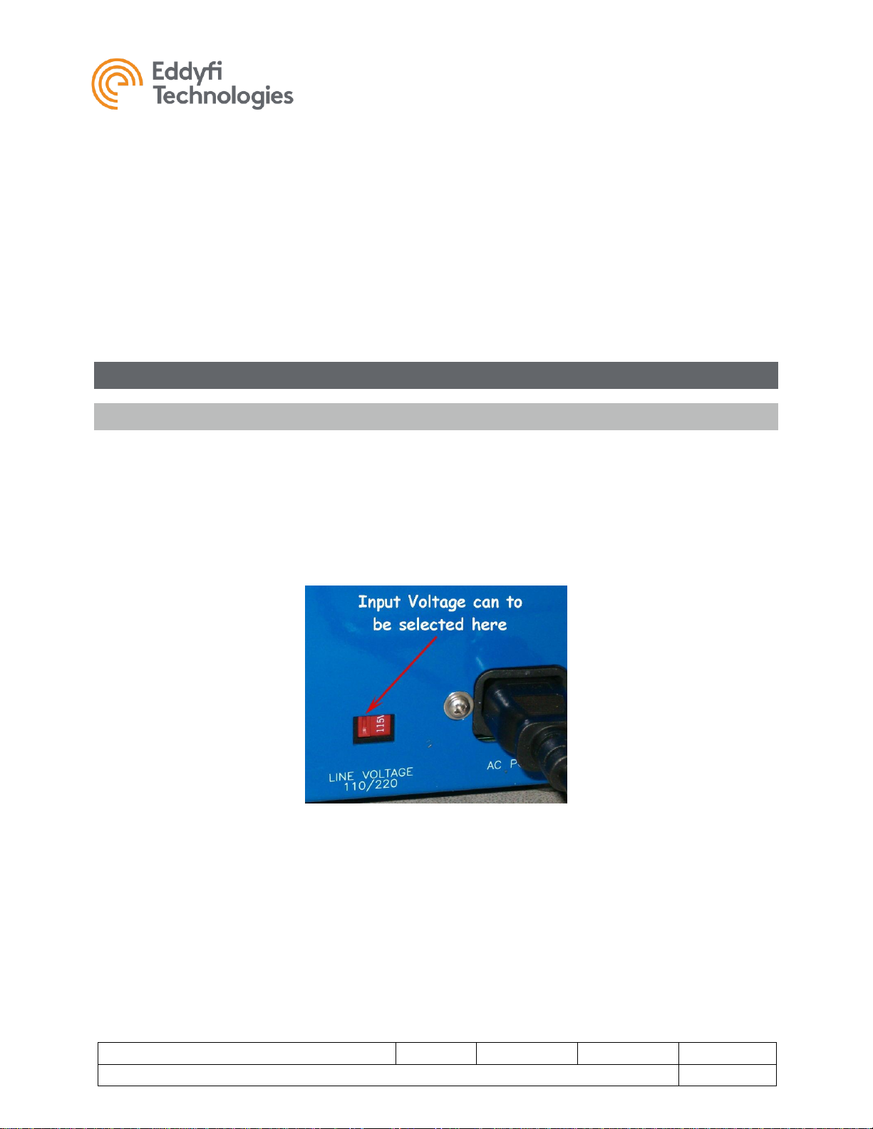
Line Voltage: When installing the system in a new location always check the line voltage selection switch
located next to the AC power cord on the controller. This switch may be set for 110VAC or 220VAC
power input and must match the line voltage of the power source. Incorrectly setting this switch will
damage the controller.
If your system includes a powered cable winch refer to the winch manual for instructions on setting its
input voltage. An incorrect voltage at the winch will damage the motor controller.
FIGURE 1: AC LINE VOLTAGE SELECTION
Power Requirement: The following figures are for a 1500-foot system and take component efficiency
and tether power loss into account.
Vehicle and Controller = 800W. Winch = 1000W. Total system = 1800W peak load.
With no winch the system can operate comfortably on a 1000W supply or inverter. With a full system we
recommend a minimum of 2000W supply or inverter. Remember to account for the power used by your
monitors and video recorders.

Minimag™
Document: UMAU011367.docm
Revision: A03
Created by: KJB
Date: 26 Sep 2019
3063241-A03
Source Location: C:\ePDM\ISLEng\products\au-micromag\manuals\UMAU011367.docm
Page 8 of 26
User Manual
The Versatrax™ controller is designed to support our tracks, cameras, and lights. Powering other
devices or equipment off the Versatrax controller is not recommended.
Generators / Inverters
If powering the system from a generator or inverter, refer to that unit’s operating manual for
recommendations on continuous and peak load ratings. These power sources may apply a reduced
output rating based on electrical load and environmental temperature. Remember to include the power
needs of any other connected devices (external monitors, recording devices, lighting, etc.) when selecting
a generator or inverter.
Video Hook-Up
The external video connectors on your Versatrax system use RCA style video jacks similar to most
monitors and video equipment. An RCA style video cable has been supplied with the controller. Some
industrial monitors may use a BNC style video jack. An RCA to BNC adapter has been supplied for this
purpose.
Video from your Versatrax controller may be connected directly to the video input of a television, or other
recording device. Please refer to your television or recording device owner’s manual.
Winch Installation
If your system includes an AC powered winch, refer to the winch manual for installation instructions.
Auxiliary Device
There is provision in the Versatrax system to allow add-on devices such as a rear facing camera, sonar,
or other vehicle electronics. A twisted pair in the tether is reserved for telemetry from this device. The
controller must be configured by setting a dip switch on the main control PCB (see Figure 4 below). The
standard configuration is to use this twisted pair for the rear camera.
• If the vehicle has a second camera, set the auxiliary dip switch to the position marked “rear
video”. This is the default position shipped from the factory. The switch must be in this position
in order to receive video from a secondary camera.
• If the spare conductors are to be used by other devices, such as sonar or on-board sensors, the
switch must be set to the position marked “spare cond.” This will route the signals to the
“Desktop Controller” connector on the controller.
 Loading...