


Inuktun Services Ltd.
2569 Kenworth Road, Suite C
Nanaimo, BC, V9T 3M4
CANADA
+1.250.729.8080
info@eddyfitechnologies.com
www.eddyfitechnologies.com
2569 Kenworth Road, Suite C
Nanaimo, BC, V9T 3M4
CANADA
+1.250.729.8080
info@eddyfitechnologies.com
www.eddyfitechnologies.com
INUKTUN MICROTRAC™

Microtrac™
Document: UMDB007595.docm
Revision: B13
Created by: KB
Date: 17 Nov 2019
3042830-B13
Source Location: C:\ePDM\ISLEng\products\db-microtracs4000\manuals\UMDB007595.docm
Page 2 of 26
User Manual
Table of Contents
About This Manual ........................................................................................................................................ 3
Description .................................................................................................................................................... 3
Specifications ............................................................................................................................................ 4
Precautions ............................................................................................................................................... 5
Certification ............................................................................................................................................... 5
Connector Pin-Out .................................................................................................................................... 6
Load and Speed Specifications ................................................................................................................ 7
Basic Loading Specifications ................................................................................................................. 7
Influences on Loading ............................................................................................................................ 8
Safety ...................................................................................................................................................... 11
System Setup .............................................................................................................................................. 13
Mounting the Track ................................................................................................................................. 13
Flange Adapter ....................................................................................................................................... 15
Connector Handling ................................................................................................................................ 16
Impulse Connector: Lubrication and Cleaning ..................................................................................... 16
Belt Installation........................................................................................................................................ 17
Maintenance ................................................................................................................................................ 22
Rinsing and Cleaning .............................................................................................................................. 22
Scheduled Maintenance and Servicing .................................................................................................. 22
Overhaul ................................................................................................................................................. 23
Parts and Repairs ....................................................................................................................................... 24
Ordering Parts/Customer Service ........................................................................................................... 24
Warranty Repairs .................................................................................................................................... 24
Factory Returns to Canada ..................................................................................................................... 25
Product/System Drawing Package Availability ....................................................................................... 25
Limited Warranty Policy .............................................................................................................................. 26

Microtrac™
Document: UMDB007595.docm
Revision: B13
Created by: KB
Date: 17 Nov 2019
3042830-B13
Source Location: C:\ePDM\ISLEng\products\db-microtracs4000\manuals\UMDB007595.docm
Page 3 of 26
User Manual
About This Manual
This manual has been prepared to assist you in the operation and maintenance of your Eddyfi
Technologies’ Inuktun equipment. Correct and prudent operation rests with the operator who must
thoroughly understand the operation, maintenance, service and job requirements. The specifications and
information in this manual are current at the time of printing.
This product is continually being updated and improved. Therefore, this manual is meant to explain and
define the functionality of the product. Furthermore, schematics or pictorials and detailed functionality
may differ slightly from what is described in this manual.
Eddyfi Technologies reserves the right to change and/or amend these specifications at any time without
notice. Customers will be notified of any changes to their equipment.
Information in this manual does not necessarily replace specific regulations, codes, standards, or
requirements of others such as government regulations.
This manual copyright © 2019 by Inuktun Robotics Inc. All rights reserved.
Description
Inuktun Microtrac™ 4000 is a small, self-contained tractor module complete with its own electric motor
and drive train. They are designed for harsh environments including confined spaces, underwater,
radioactive areas, and in some harsh chemical solutions. Microtrac modules may be operated in pairs to
make a steerable platform or used in-line to fit in small spaces. Applications include storm and sewer
pipe inspection, use with bomb disposal robots, industrial inspection, and custom vehicles for nuclear
facility inspection and waste cleanup. Microtracs are made in three varieties: aluminum, brass or
stainless steel. The choice of track material will depend on its end use. In all versions, the final drive
power is delivered through a deep lug rubber track belt in either standard or extended length. As well, the
track can be configured for both left-hand or right-hand operation.
Microtrac™
Document: UMDB007595.docm
Revision: B13
Created by: KB
Date: 17 Nov 2019
3042830-B13
Source Location: C:\ePDM\ISLEng\products\db-microtracs4000\manuals\UMDB007595.docm
Page 4 of 26
User Manual
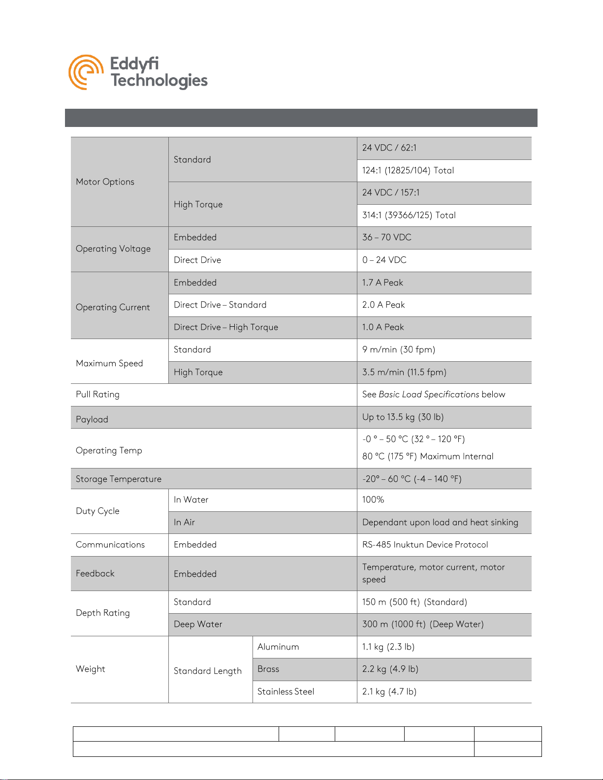
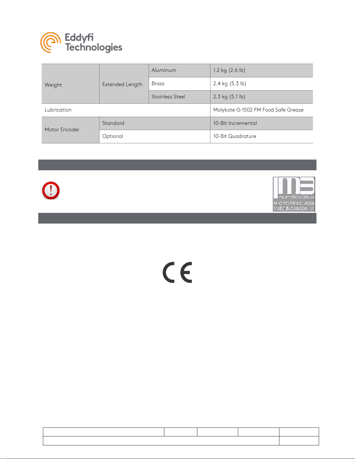
Specifications
Microtrac™
Document: UMDB007595.docm
Revision: B13
Created by: KB
Date: 17 Nov 2019
3042830-B13
Source Location: C:\ePDM\ISLEng\products\db-microtracs4000\manuals\UMDB007595.docm
Page 5 of 26
User Manual
Precautions
IMPORTANT: When configuring a 70V system, check to see if the tracks are
compatible. Older versions of 4000 series Microtracs™ are not 70V
compatible. Look for the Wide Input Voltage symbol \V/ located on the side
plate of the track indicating 70V compatibility.
Certification
The product is built in accordance with:
Machinery Directive 2006/42/EC, and
Electromagnetic Compatibility Directive 2004/108/EC and Directive 2014/30/EU
Microtrac™
Document: UMDB007595.docm
Revision: B13
Created by: KB
Date: 17 Nov 2019
3042830-B13
Source Location: C:\ePDM\ISLEng\products\db-microtracs4000\manuals\UMDB007595.docm
Page 6 of 26
User Manual
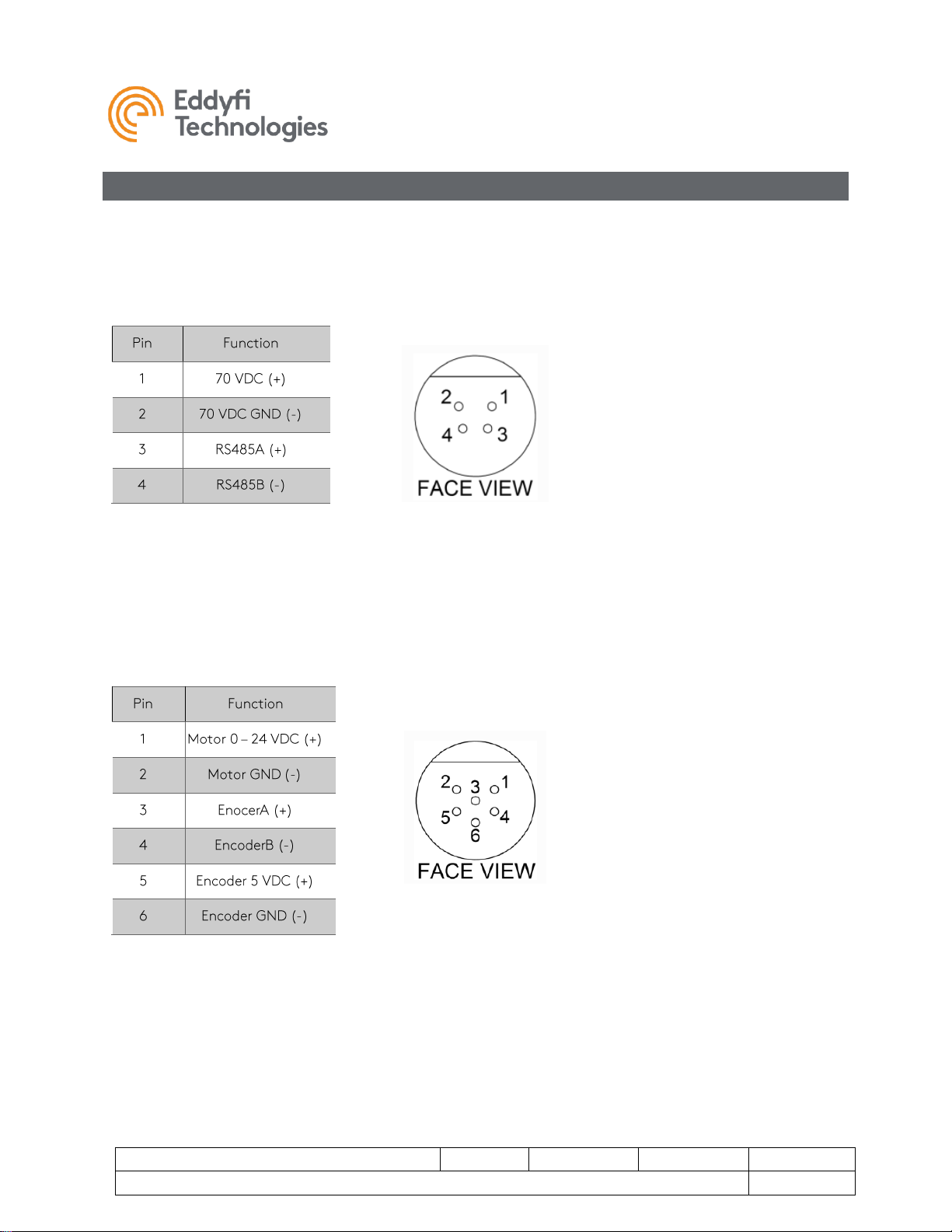
Connector Pin-Out
Standard Tracks
The embedded Microtrac 4000™ uses a 4-pin Impulse IE-55 connector on the side of the track to connect
power and communications. Contact Eddyfi Technologies for details of the RS-485 control protocol.
Note: Pin-out is shown for the Bulkhead Connector on the track.
Direct Drive Tracks
The embedded Microtrac 4000 uses a 6-pin Impulse IE-55 connector on the side of the track to connect
motor power, encoder power and encoder signals. Contact Eddyfi Technologies for details of the
encoder feedback.
Note: Pin-out is shown for the Bulkhead Connector on the track.
Microtrac™
Document: UMDB007595.docm
Revision: B13
Created by: KB
Date: 17 Nov 2019
IPN: 3042830-B13
Source Location: C:\ePDM\ISLEng\products\db-microtracs4000\manuals\UMDB007595.docm
Page 7 of 26
User Manual
Load and Speed Specifications
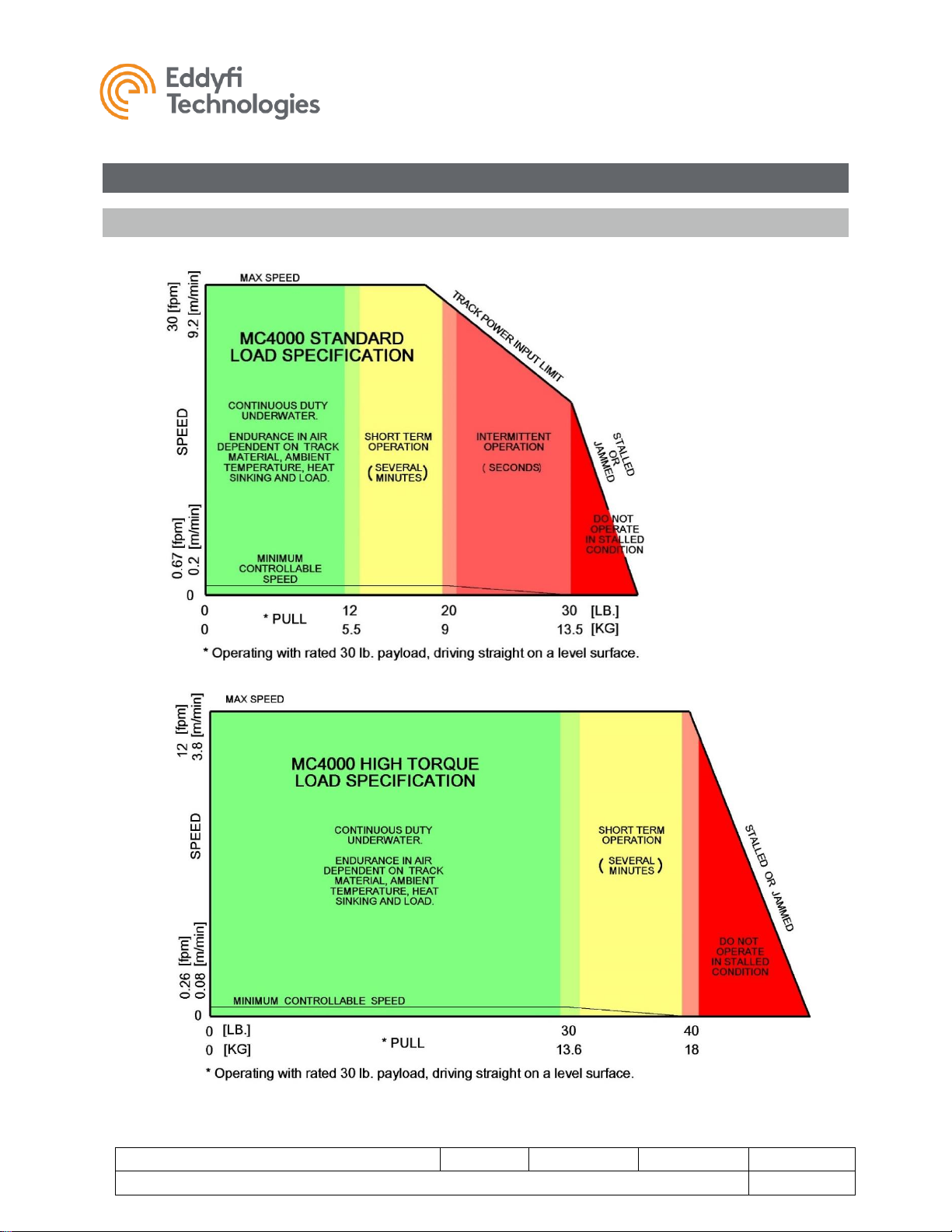
Basic Loading Specifications
Microtrac™
Document: UMDB007595.docm
Revision: B13
Created by: KB
Date: 17 Nov 2019
IPN: 3042830-B13
Source Location: C:\ePDM\ISLEng\products\db-microtracs4000\manuals\UMDB007595.docm
Page 8 of 26
User Manual
The above diagram details the speed and loading specifications of the standard and high-torque
Microtracs™. There are four regions defining performance:
• Continuous Duty: Preferred operating region.
• Short Term Operation: Operation permitted for several minutes.
• Intermittent: Surge loading allowable for a few seconds at a time.
• Stalled / Jammed Condition: Automatic limiting is engaged to protect the motor and gearing.
Do not operate the track in the stalled or jammed condition.
Influences on Loading
For a typical tracked vehicle there are multiple factors that can increase load and diminish track
performance. These include the following and are detailed below:
• Additional Payload
• Inclines
• Effects of Differential Steering (skid steering with parallel tracks)
• Curved Geometry of a pipe
• Elevated Temperature / Poor Heat Sinking / Thermal Shut-Down
Additional Payload
Additional Payload may be added to the track, but the expected pull performance must be de-rated as
per the calculation below. Additional payload also affects differential steering, inclines and curved pipe
geometry (see below).
Pull Reduction = 0.25 x Extra Weight
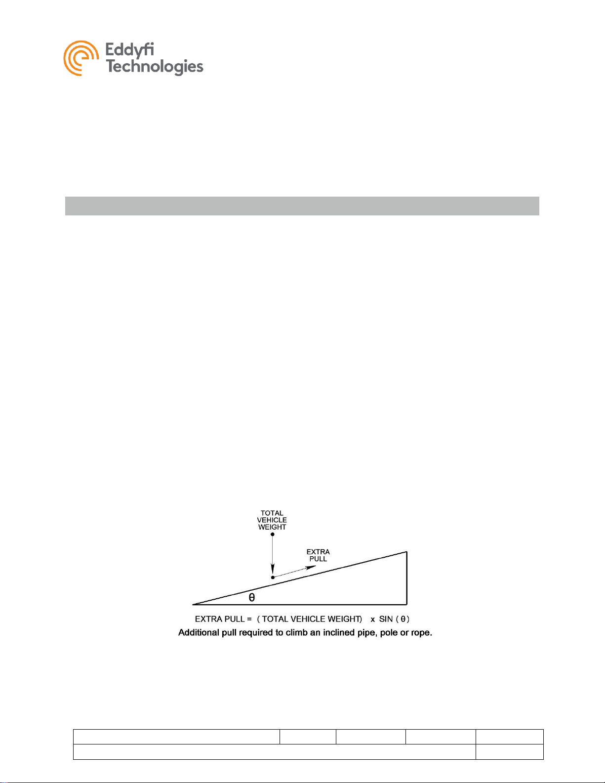
Inclines
Inclines cause the track to lift the vehicle weight against gravity and increase the track pulling load.
Calculate the incline load using the equation below. Magnetic downforce does not affect loading from
inclines — only forces from gravity. Note that the constant load from gravity becomes a significant factor
on vertical surfaces because the motor is working to resist the load even when the track is stopped.

Microtrac™
Document: UMDB007595.docm
Revision: B13
Created by: KB
Date: 17 Nov 2019
IPN: 3042830-B13
Source Location: C:\ePDM\ISLEng\products\db-microtracs4000\manuals\UMDB007595.docm
Page 9 of 26
User Manual
Differential Steering
Differential Steering means steering by varying the speed of two tracks such as with a tank or bulldozer.
During the steering process the tracks are dragged sideways in addition to forward / backward
movement. The sideways movement adds to the total track load and requires extra torque from the
motor. The greatest increase in loading occurs during a spot turn; the load being calculated as per the
equation below. A typical 13.5 kg (30 lb) magnetic VT100 with 13.5 kg (30 lb) of down-force on a surface
with friction coefficient µ = 0.5 will experience an additional 8kg (18 lb) load per track to execute the spot
turn. When steering on a vertical surface include only the magnetic down-force for the differential
steering load calculation.
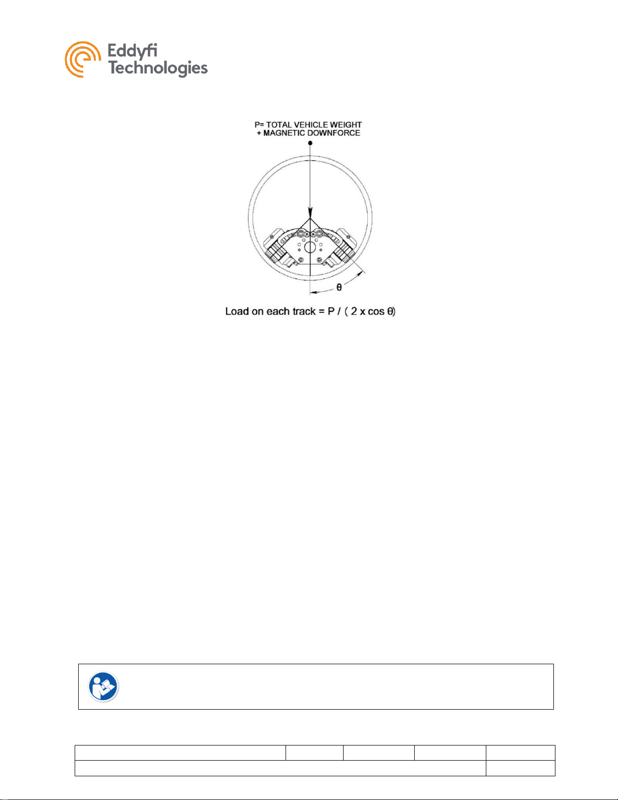
Curved Geometry
Curved Geometry inside a pipe will increase the payload on a track depending on the angle of contact
with the pipe. For nearly flat tracks the increase is small. For a contact angle of 60°, the load is doubled.
The same calculation is used for a track contacting the outside of a pipe. Include both vehicle weight and
magnetic downforce for this calculation.
Microtrac™
Document: UMDB007595.docm
Revision: B13
Created by: KB
Date: 17 Nov 2019
IPN: 3042830-B13
Source Location: C:\ePDM\ISLEng\products\db-microtracs4000\manuals\UMDB007595.docm
Page 10 of 26
User Manual
Elevated Temperature & Thermal Shutdown
‘Duty Cycle’ refers to the length of time a track can run before overheating, and the following time
required to cool down. The duty cycle of the Microtracs 4000™ depends on:
• Track Material Thermal Conductivity (Aluminum, Brass = Good; Stainless = Poor)
• Ambient Temperature
• Track Load & Speed
• Wet / Dry Operation
• Heat Sinking
A track typically converts about 25% of the electrical input into motive mechanical power with the
remainder being converted into waste heat transferred to the environment outside the track. When run
continually at maximum power in a warm environment - up to 50 °C (120 °F), the tracks can heat up to
the maximum temperature within ½-hour. However, this does not represent normal operation. Typical
usage will include much starting and stopping for visual/NDT inspections and moderate loading for most
of a pipe run for pulling tether – so reaching the thermal limit of the track is not expected to be a common
operational concern. When tracks are bolted to a chassis, it further acts as a heat sink to help cool the
tracks.
When a tracks internal temperature reaches 80 °C (175 °F) it will automatically shut down and wait until
its internal temperature drops below 70 °C (160 °F) before restarting. If the tracks are operating
underwater, such as in a flooded pipe, heat transfer is excellent, and the duty cycle may be considered
continuous.
Note: Stainless steel tracks will require special consideration for cooling, as they
reach thermal shutdown sooner due to the extremely poor thermal conductivity of
the stainless steel itself.
Microtrac™
Document: UMDB007595.docm
Revision: B13
Created by: KB
Date: 17 Nov 2019
IPN: 3042830-B13
Source Location: C:\ePDM\ISLEng\products\db-microtracs4000\manuals\UMDB007595.docm
Page 11 of 26
User Manual
Safety
In order to be able to use this product properly and safely, every user must first read these operating
instructions and observe the safety instructions contained therein. Take care of these operating
instructions and keep them in a place where they can be accessed by everyone.
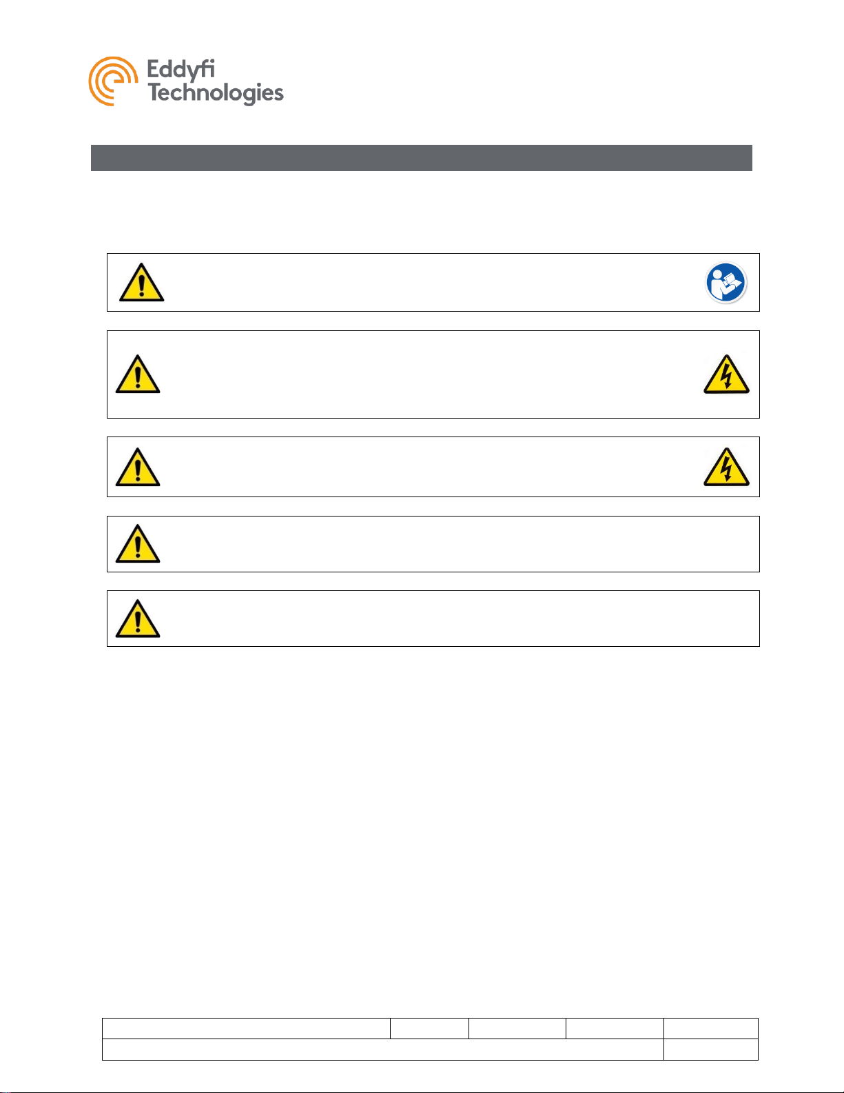
CAUTION: Failure to follow these safety instructions may result in injury or
equipment damage.
WARNING: High Voltage 36-70 VDC. If the equipment is powered from a source
other than an Eddyfi Technologies provided controller, the power supplied to the
product must have reinforced isolation from the mains with no reference to earth
ground.
CAUTION: Disconnecting the track while the power is on can cause damage to the
camera. Disconnect the power source before servicing the product.
CAUTION: High Temperature. Under rated operating conditions this track can
become very hot, up to 80 °C (175 °F).
WARNING: Spark Hazard - Under no circumstances should this equipment be
used in a potentially explosive atmosphere.
• The Microtrac 4000™ is an industrial product. All personnel operating or maintaining this
equipment must be competently trained.
• There are no user serviceable parts inside. This product may be serviced only by qualified
technicians or trained personnel.
• Eddyfi equipment is used in many varied environments from hot/dry to confined spaces to deep
underwater. Such diverse environment risks must be addressed by the operators who are trained
to work in such surroundings. As such, the operator is responsible to determine safe site setup
and appropriate procedures for operation and maintenance of the equipment.
• Appropriate personal protective equipment (PPE) must be worn while operating and maintaining
the equipment.
• Do not use the product or any component exposed to pressures higher than the rated working
pressure.
In addition, observe the following precautions when cleaning or servicing the Microtrac 4000™
• Do not operate the track with a damaged connector or cable. Inspect connectors and cables
regularly for damage.
• Avoid creating a pinching hazard when designing a vehicle based on these tracks.

Microtrac™
Document: UMDB007595.docm
Revision: B13
Created by: KB
Date: 17 Nov 2019
IPN: 3042830-B13
Source Location: C:\ePDM\ISLEng\products\db-microtracs4000\manuals\UMDB007595.docm
Page 12 of 26
User Manual
• Lay the track on its side if you are powering it up on the workbench.
• DC-Controlled tracks (without internal driver) must be protected by current limiting either by fuse
or electronically by the power supply. Current limiting and fuses are included standard with
Inuktun system controllers.
Call the Eddyfi Technologies Service department for assistance or service if needed.
Microtrac™
Document: UMDB007595.docm
Revision: B13
Created by: KB
Date: 17 Nov 2019
IPN: 3042830-B13
Source Location: C:\ePDM\ISLEng\products\db-microtracs4000\manuals\UMDB007595.docm
Page 13 of 26
User Manual
System Setup
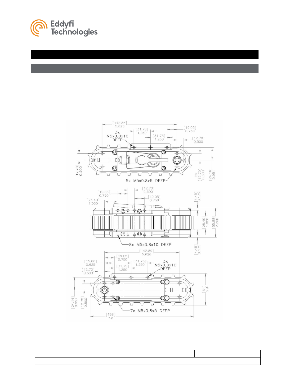
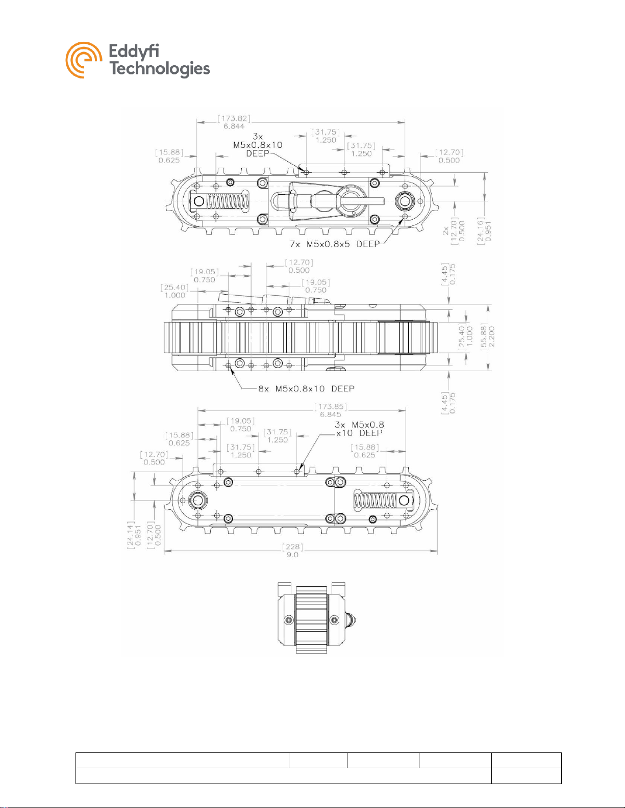
Mounting the Track
Microtracs™ are provided with a variety of mounting locations on the sides, top and bottom. Use of any
three mounting holes is enough to support the rated load. When using the side flange holes, make sure
the screws do not protrude beyond the flange and into the track belt. Mounting holes are also provided
on the sides of the Microtracs for in-line or chassis side-wall mounting. Note that hole depths can be
different depending on the position. All holes are tapped M5. Mounting hole locations are shown below
for standard and extended tracks.
MICROTRAC 4000 STANDARD
Microtrac™
Document: UMDB007595.docm
Revision: B13
Created by: KB
Date: 17 Nov 2019
IPN: 3042830-B13
Source Location: C:\ePDM\ISLEng\products\db-microtracs4000\manuals\UMDB007595.docm
Page 14 of 26
User Manual
MICROTRAC 4000 EXTENDED LENGTH

Microtrac™
Document: UMDB007595.docm
Revision: B13
Created by: KB
Date: 17 Nov 2019
IPN: 3042830-B13
Source Location: C:\ePDM\ISLEng\products\db-microtracs4000\manuals\UMDB007595.docm
Page 15 of 26
User Manual
MICROTRAC™ 4000 DEEP WATER
Flange Adapter
Flange adapters come standard with the Microtrac 4000 for mounting to chassis plates or legacy
systems. Tracks can be configured for left or right-hand operation depending on which side the flanges
are mounted – top or bottom. Flanges may also be ordered with Imperial threads for non-metric
installations.
MICROTRAC FLANGE ADAPTER

Microtrac™
Document: UMDB007595.docm
Revision: B13
Created by: KB
Date: 17 Nov 2019
IPN: 3042830-B13
Source Location: C:\ePDM\ISLEng\products\db-microtracs4000\manuals\UMDB007595.docm
Page 16 of 26
User Manual
Connector Handling
Connectors are an essential part of system reliability. They should be properly maintained and cared for
to ensure long life and reliability. It is recommended to follow these steps to help prevent damage and
increase the life of connectors.
• Always put the cap back on the tether bulkhead when the tether is disconnected
• Always inspect the end of the connector prior to engaging
• Never plug in a dirty or damaged connector
• Visually align key-ways or locating pins prior to engaging the connector
• Always fully engage or tighten the connector
• Secure locking collars finger tight
• Install dummy plugs on unused connectors
• Disconnect by pulling straight, not on an angle
• Do not pull on the cable to disengage the connector
IMPORTANT: Never “Hot Plug” any connector, this will result in internal damage to the
electronics. Power down the system prior to connecting the inspection system tether.
Note:
Never use WD-40 or similar solvent-based fluids on connectors or crawlers. These will cause
the rubber parts of the connector or crawler to soften and swell rendering them inoperable.
Impulse Connector: Lubrication and Cleaning
• Lubricate mating surfaces regularly with 3M Silicone spray or equivalent, DO NOT GREASE
• Lubricate O-rings with Molykote 111 or equivalent
• Use dust caps to protect connectors wherever possible
• Clean connectors with soap and fresh water, rinse out with alcohol and allow connector to air
dry before using.

Microtrac™
Document: UMDB007595.docm
Revision: B13
Created by: KB
Date: 17 Nov 2019
IPN: 3042830-B13
Source Location: C:\ePDM\ISLEng\products\db-microtracs4000\manuals\UMDB007595.docm
Page 17 of 26
User Manual
Belt Installation
Microtrac 4000™ belt replacement has been made easy by a spring tensioning system (except for
manual option) that automatically aligns and tensions the track belt. Procedures vary between the
standard-length and extended-length track as detailed below.
Standard Length Track
1. Remove the mounting flange from the label side of the track.
2. Release the belt tension. Notice the tensioning spring is compressed by a captured nut. Turn the
tensioning screws (counter clock-wise) until all the spring tension is released and both nuts are
resting against the housing shoulder. The tensioning screws do not need to be fully removed leave them in place. Procedure is the same for the manual tensioning option.
3. Remove the front side plate as shown, exposing the three screws on the front idler wheel.
Remove the three screws and the idler wheel flange.

Microtrac™
Document: UMDB007595.docm
Revision: B13
Created by: KB
Date: 17 Nov 2019
IPN: 3042830-B13
Source Location: C:\ePDM\ISLEng\products\db-microtracs4000\manuals\UMDB007595.docm
Page 18 of 26
User Manual
4. The belt can now be lifted from the track. The track is now ready for cleaning or installation of a
new belt.
5. When replacing the belt ensure the drive wheel lugs are engaged with the belt before slipping the
belt back over the idler wheel.
6. Replace the idler wheel flange and side plate.

Microtrac™
Document: UMDB007595.docm
Revision: B13
Created by: KB
Date: 17 Nov 2019
IPN: 3042830-B13
Source Location: C:\ePDM\ISLEng\products\db-microtracs4000\manuals\UMDB007595.docm
Page 19 of 26
User Manual
7. Tension the belt by turning the tensioning screws clockwise until the captured nuts bottom out in
their groove. They will be in position as shown below. Again – the tensioning screws stay in
place.
Manual tensionioning option is identical except that belt tension is set by screw depth – adjust the
tensioning screws until the belt is tensioned. Belt should be taut but still allow some deflection.

Microtrac™
Document: UMDB007595.docm
Revision: B13
Created by: KB
Date: 17 Nov 2019
IPN: 3042830-B13
Source Location: C:\ePDM\ISLEng\products\db-microtracs4000\manuals\UMDB007595.docm
Page 20 of 26
User Manual
Extended Length Track
1. Remove the drive wheel cover and mounting flange on the side shown. The opposite mounting flange
can remain in place.
2. Compress the tensioning springs using M6 x 16 or longer jack screws.
The jack screws are fully removed from the track when the belt is replaced.

Microtrac™
Document: UMDB007595.docm
Revision: B13
Created by: KB
Date: 17 Nov 2019
IPN: 3042830-B13
Source Location: C:\ePDM\ISLEng\products\db-microtracs4000\manuals\UMDB007595.docm
Page 21 of 26
User Manual
3. Manual Tension: Thread the tensioning screws on both sides of the track into the main housing
(CW) to release the belt tension.
4. Pull the belt off the track from the rear wheel first. The track is now ready for cleaning or installation
of a new belt.

Microtrac™
Document: UMDB007595.docm
Revision: B13
Created by: KB
Date: 17 Nov 2019
IPN: 3042830-B13
Source Location: C:\ePDM\ISLEng\products\db-microtracs4000\manuals\UMDB007595.docm
Page 22 of 26
User Manual
Maintenance
Rinsing and Cleaning
After every mission check to see if the tracks need cleaning. To maintain top performance of the
Microtrac™ units, it is important to prevent excessive buildup of dirt under the track belt. A buildup will
increase the belt tension, causing the track to lose speed and pulling ability. Ultimately excessive tension
may stretch and ruin the track belt.
1. If the tracks have been used in salt water, thoroughly rinse the tracks with fresh water prior to being
stored away. Accelerated corrosion will result if the inspection system is not rinsed properly. Pay
close attention to rinsing and cleaning the spring and underneath the track belt.
2. Use an open hose or tap at regular water line pressure for rinsing – use a mild detergent and soft
brush. Do not pressure wash the equipment – water will be forced into the track at these high
pressures.
If it is necessary to apply aggressive cleaning fluids, consult the factory before use. Clean away
any dirt, grit or build-up near joints or moving parts. Also clean the drive wheel teeth, wear strip
and idler wheels.
CAUTION: Do not use a pressure washer to clean the camera. Very highpressure water can push past seals and flood the components resulting in
electrical damage or personal injuries.
Scheduled Maintenance and Servicing
Microtrac crawlers are designed to provide reliable service accompanied by a minimum downtime for
maintenance. The frequency of maintenance and/or repairs will be largely dictated by the type of use and
the environments the units are subjected to. Eddyfi recommends the following maintenance procedures
in addition to normal equipment operational inspections.
Daily
Daily or before each use of the Microtrac units:
1. Tracks with Spring Tensioners - Check that the belt tensioning springs are freely moving. This
can be done by pulling up on the edge of the track belt with your thumb – the belt should have a
small amount of give. If the springs are bottomed out, the material under the belt must be
removed before deployment to avoid damage and to attain best performance.
Tracks with Manual Belt Tensioners – Check that the tensioning screws have not slackened. Belt
should be taut but manual deflection with normal hand force should be possible. If the belts feel
too tight, check for debris or build-up underneath the belts and remove if present. Do not
overtighten belts or performance could be degraded, and damage could occur.
2. Visually inspect the Microtrac and track belt for damage; if the track belt is torn or stretched it
should be replaced.

Microtrac™
Document: UMDB007595.docm
Revision: B13
Created by: KB
Date: 17 Nov 2019
IPN: 3042830-B13
Source Location: C:\ePDM\ISLEng\products\db-microtracs4000\manuals\UMDB007595.docm
Page 23 of 26
User Manual
3. Ensure that all fasteners are in place and secure.
Weekly
1. Tracks with Spring Tensioners - In addition to the daily check, examine the condition of the
tension springs at least once per week. Worn or corroded springs may weaken and cause low
belt tension and idler wheel misalignment.
2. Verify by visual inspection that there are no traces of grease near or on the sides of the drive
wheel and the track belt. This would indicate that the grease seals may have been damaged by
debris or have become worn by abrasion.
3. If necessary, remove the belt and thoroughly clean the track.
Overhaul
Eddyfi recommends that the Microtracs™ be thoroughly serviced once a year or after 600 hours of
operation. This includes complete disassembly, cleaning and inspection of the Microtrac components
with focus on the drivetrain, bearings, output shaft and seals. At this time the track is re-lubricated.
For extended service and maximum reliability of your Microtracs, Eddyfi offers a factory overhaul. The
factory overhaul constitutes an investment by the equipment owner in preventative maintenance. As
such, the overhaul should be considered discretionary. In the overhaul, the track unit is completely
disassembled. All internal components including the motor, driver, bevel gears, bearings, and seals are
inspected and replaced where necessary.

Microtrac™
Document: UMDB007595.docm
Revision: B13
Created by: KB
Date: 17 Nov 2019
IPN: 3042830-B13
Source Location: C:\ePDM\ISLEng\products\db-microtracs4000\manuals\UMDB007595.docm
Page 24 of 26
User Manual
Parts and Repairs
Ordering Parts/Customer Service
Spare and/or replacement parts are available for your product and can be ordered directly from your local
office.
When ordering parts always make sure to quote the sales order acknowledgement (SOA) number and/or
the serial number of the system component in question.
Eddyfi Robotics Inc. (Canadian Headquarters and Manufacturing Location)
2569 Kenworth Road, Suite C
Nanaimo, BC, V9T 3M4
CANADA
TF 1.877.468.5886
T +1.250.729.8080
info@eddyfi.com
www.eddyfitechnologies.com
Eddyfi Technologies – US (American Authorized Distributor and Service Centre)
812 W 13th Street
Deer Park, TX, 77536
USA
T +1.281.542.3292
info@eddyfi.com
www.eddyfitechnologies.com
Warranty Repairs
Warranty conditions are specified in the Warranty section. Should any conditions of the manufacturer’s
warranty be breached, the warranty may be considered void. All returned items must be sent prepaid to
Eddyfi Technologies at the above address.

Microtrac™
Document: UMDB007595.docm
Revision: B13
Created by: KB
Date: 17 Nov 2019
IPN: 3042830-B13
Source Location: C:\ePDM\ISLEng\products\db-microtracs4000\manuals\UMDB007595.docm
Page 25 of 26
User Manual
Factory Returns to Canada
Some sub-assemblies of your Eddyfi Technologies product are not field-serviceable and may need to
return to the factory for repair. Warranty claims must return to the factory for evaluation.
To return an item for evaluation or repair, first contact Eddyfi Technologies at our toll-free number or email address. Eddyfi Technologies will supply a Return Merchandise Authorization (RMA) number with
detailed shipping and customs instructions. Items shipped without an RMA number will be held at Eddyfi
Technologies until the correct paperwork is completed. If cross-border shipments are not labelled as per
the instructions, the items may be held by customs and issued additional fees.
All returned items must be sent prepaid unless other specific arrangements have been made.
When the product or system is being shipped anywhere by courier or shipping company, it must be
packaged in the original packaging it was received in. This measure greatly reduces the consequences of
rough handling and subsequent shipping damage.
Eddyfi Technologies cannot be held responsible for damages due to improper packaging. Shipping
damage may have significant impact on repair turnaround times.
Product/System Drawing Package Availability
Mechanical assembly and electrical wiring diagram drawing packages for your equipment are available in
PDF format upon request. Printed copies may also be purchased from Eddyfi Technologies. Contact your
local sales contact for more information.

Microtrac™
Document: UMDB007595.docm
Revision: B13
Created by: KB
Date: 17 Nov 2019
IPN: 3042830-B13
Source Location: C:\ePDM\ISLEng\products\db-microtracs4000\manuals\UMDB007595.docm
Page 26 of 26
User Manual
Limited Warranty Policy
Eddyfi Technologies will repair or replace, at its expense and at its option, any system or component,
subject to the limitations and / or exclusions specified herein, which in normal use has proven to be
defective in workmanship or material provided that, within one (1) year of the purchase date, the original
purchaser returns the product prepaid, accompanied by proof of purchase, from a sales agent authorized
by Eddyfi Technologies, and provides Eddyfi Technologies with reasonable opportunity to verify the
alleged defect by inspection.
Warranty Limitations and/or Exclusions:
1. This warranty does not apply to light bulbs.
2. Batteries, fuses, transistors, integrated circuit modules (IC’s), voltage regulating devices and electrical
plugs and / or connectors are warranted to be free from defects in material and workmanship for a
period of ninety (90) days from the date of shipment to the original purchaser.
3. Any article purchased from, but not manufactured by, Eddyfi Technologies is sold with only such
warranties as are made by the manufacturer therein. Eddyfi Technologies only warrants that it has
title thereto, free of all liens or encumbrances.
4. This warranty does not apply to units which are damaged by connection to improperly wired AC
receptacles.
5. Track belts, tethers, view ports and other components subject to wear through abrasion are
warranted to be free from defects in material and workmanship for a period of ninety (90) days from
the date of shipment to the original purchaser.
6. Any damage caused by failure to observe proper packing or to observe instructions for operation and
maintenance as contained in the Instruction Manual furnished with the equipment, by accident in
transit or elsewhere, will not be covered by the warranty.
7. Repairs are warranted for 90 days.
Eddyfi Technologies may require that certain components may be returned, prepaid, to a manufacturer’s
authorized station for inspection and repair or replacement.
Eddyfi Technologies will not be responsible for any asserted defect which has resulted from Acts of God,
normal wear, misuse, abuse, improper configuration, repair, or alteration made, or specifically authorized
by, anyone other than a representative of Eddyfi Technologies authorized to do so. The giving of, or
failure to give, any advice or recommendation by Eddyfi Technologies shall not constitute any warranty
by, or impose any liability on, Eddyfi Technologies.
The foregoing constitutes the sole and exclusive remedy of the purchaser and the exclusive liability of
Eddyfi Technologies and is in lieu of any and all other warranties, express, implied or statutory as to
merchantability, fitness for purpose sold, description, quality productiveness, or any other matter. Under
no circumstances shall Eddyfi Technologies be liable for special, incidental or consequential damages, or
for delay in performance of this warranty.
 Loading...