

EDAN SE-601 Series User Manual

EDAN INSTRUMENTS, INC.
SE-601 Series
Electrocardiograph
Manual Ver: 1.3
Release Date: Oct. 2009
Part Number: MS1R-110286-1.3

P/N: MS1R-110286-1.3
Copyright
© Copyright EDAN INSTRUMENTS, INC. 2008-2009. All rights reserved.
Statement
This manual will help you understand the operation and maintenance of the product better. It is
reminded that the product shall be used strictly complying with this manual. User’s operation
failing to comply with this manual may result in malfunction or accident for which EDAN
INSTRUMENTS, INC. (hereinafter called EDAN) can not be held liable.
EDAN owns the copyrights of this manual. Without prior written consent of EDAN, any
materials contained in this manual shall not be photocopied, reproduced or translated into other
languages.
Materials protected by the copyright law, including but not limited to confidential information
such as technical information and patent information are contained in this manual, the user shall
not disclose such information to any irrelevant third party.
The user shall understand that nothing in this manual grants him, expressly or implicitly, any
right or license to use any of the intellectual properties of EDAN.
EDAN holds the rights to modify, update, and ultimately explain this manual.
Product Information
Product Name: Electrocardiograph
Model: SE-601A, SE-601B, SE-601C
Responsibility of the Manufacturer
The manufacturer only considers itself responsible for any effect on safety, reliability and
performance of the equipment if:
Assembly operations, extensions, re-adjustments, modifications or repairs are carried out by
persons authorized by the manufacturer, and
The electrical installation of the relevant room complies with national standards, and
The instrument is used in accordance with the instructions for use.
Upon request, the manufacturer may provide, with compensation, necessary circuit diagrams, and
other information to help qualified technician to maintain and repair some parts, which the
manufacturer may define as user serviceable.
Using This Label Guide
This guide is designed to give key concepts on safety precautions.
I

WARNING
A WARNING label advises against certain actions or situations that could result in personal
injury or death.
CAUTION
A CAUTION label advises against actions or situations that could damage equipment, produce
inaccurate data, or invalidate a procedure.
NOTE: A NOTE provides useful information regarding a function or a procedure.
Revision History
Date ECO# / ECR# Version Description
2008/12 1.0 1st edition
2009/01 ECO-SE-9001 1.1
2009/03 ECO-SE-9005 1.2
2009/10 ECR-SE-9044 1.3
Added some information according
to EC11
Replaced the Filter Setup interface
and the More Setup interface.
Replaced the Patient Information
window and the Record Setup
interface. Added the interfaces of
SE-601A.
II

Table of Contents
Chapter 1 Safety Guidance ...........................................................................................................1
1.1 Intended Use ........................................................................................................................... 1
1.2 Warnings and Cautions........................................................................................................... 1
1.2.1 Safety Warnings ............................................................................................................... 1
1.2.2 Battery Care Warnings .....................................................................................................3
1.2.3 General Cautions.............................................................................................................. 3
1.2.4 Cleaning & Disinfection Cautions ................................................................................... 4
1.3 List of Symbols....................................................................................................................... 5
Chapter 2 Introduction..................................................................................................................8
2.1 Top Panel ................................................................................................................................8
2.2 Keyboard and Keys ................................................................................................................9
2.3 Rear Panel............................................................................................................................. 10
2.4 Right Panel ........................................................................................................................... 11
2.5 Bottom Panel ........................................................................................................................14
2.6 Function Features .................................................................................................................15
Chapter 3 About SE-601 Application.........................................................................................16
3.1 Selecting Menu Functions .................................................................................................... 16
3.2 Entering Data........................................................................................................................ 17
3.3 Selecting an Option from a List............................................................................................ 18
3.4 About the Main Interface...................................................................................................... 18
3.5 About the System Setup Interface ........................................................................................22
3.6 About the File Manage Interface .......................................................................................... 23
Chapter 4 Operation Preparations.............................................................................................27
4.1 Power and Earthing ..............................................................................................................27
4.2 Loading/Replacing Recorder Paper...................................................................................... 28
4.3 Preparing the Patient............................................................................................................. 30
4.3.1 Instructing the Patient ....................................................................................................30
4.3.2 Preparing the Skin.......................................................................................................... 30
4.4 Connecting the Patient Cable to the Electrocardiograph and Electrodes ............................. 31
4.5 Attaching Electrodes to the Patient.......................................................................................31
4.5.1 Reusable Electrodes ....................................................................................................... 32
4.5.2 Disposable Electrodes .................................................................................................... 34
4.6 Inspection Before Power-On ................................................................................................36
Chapter 5 Switching On the Electrocardiograph......................................................................37
Chapter 6 Entering Patient Information...................................................................................38
6.1 Entering Patient ID ............................................................................................................... 38
6.2 Entering Other Information ..................................................................................................39
Chapter 7 Printing ECG Reports ...............................................................................................40
7.1 Auto Mode ............................................................................................................................ 40
7.2 Manual Mode........................................................................................................................ 42
7.3 Rhythm Mode ....................................................................................................................... 44
7.4 R-R Mode ............................................................................................................................. 45
7.5 Transmitting ECG Data to the PC ........................................................................................47
7.5.1 Transmitting ECG Data Through the Serial Port ........................................................... 47
III

7.5.2 Transmitting ECG Data Through the Net Port............................................................... 47
7.6 Copy Printing........................................................................................................................ 48
7.7 ECG Reports......................................................................................................................... 48
7.7.1 ECG Reports in the Auto Mode..................................................................................... 48
7.7.1.1 Examples of 6×2+1rhy ............................................................................................48
7.7.1.2 Example of 3×4+1rhy.............................................................................................. 50
7.7.2 ECG Reports in the Rhythm Mode ................................................................................ 51
7.7.3 ECG Reports in the Manual Mode.................................................................................51
7.7.4 ECG Reports in the R-R Mode ......................................................................................52
7.7.5 ECG Reports Printed by the USB Printer ...................................................................... 54
Chapter 8 Managing Files...........................................................................................................56
8.1 Storage Upgrade Function .................................................................................................... 58
8.2 Transmitting Files to the PC ................................................................................................. 58
8.2.1 Transmitting Files Through the Serial Port.................................................................... 59
8.2.2 Transmitting Files Through the Net Port .......................................................................60
8.3 Copying Files Between SE-601 and the U Disk................................................................... 62
8.4 Editing Patient Information .................................................................................................. 64
8.5 Deleting Files........................................................................................................................ 65
8.6 Previewing a File (Only for SE-601B/C) .............................................................................66
8.7 File Printing .......................................................................................................................... 68
Chapter 9 System Setup...............................................................................................................69
9.1 Work Mode Setup ................................................................................................................. 69
9.1.1 Specifying Work Mode ..................................................................................................70
9.1.2 Specifying Manual Style................................................................................................ 70
9.1.3 Specifying Rhythm Style ...............................................................................................71
9.1.4 Specifying Auto Style .................................................................................................... 71
9.1.5 Specifying Sampling Mode............................................................................................ 72
9.1.6 Specifying Recording Sequence ....................................................................................72
9.1.7 Inputting Sampling Time................................................................................................ 73
9.2 Filter Setup ...........................................................................................................................73
9.2.1 Setting AC Filter ............................................................................................................74
9.2.2 Setting EMG Filter......................................................................................................... 74
9.2.3 Setting DFT Filter .......................................................................................................... 74
9.2.4 Setting Lowpass Filter.................................................................................................... 75
9.3 Record Setup......................................................................................................................... 75
9.3.1 Specifying Recording Device ........................................................................................76
9.3.2 Selecting Paper Marker.................................................................................................. 76
9.3.3 Selecting Patient Information......................................................................................... 78
9.3.4 Setting Speed.................................................................................................................. 79
9.3.5 Setting Gain.................................................................................................................... 79
9.3.6 Selecting Template ......................................................................................................... 79
9.3.7 Selecting Measure .......................................................................................................... 79
9.3.8 Selecting Minnesota Code.............................................................................................. 80
9.3.9 Selecting Analysis.......................................................................................................... 80
9.3.10 Selecting Position Marker............................................................................................ 80
9.4 Lead Setup ............................................................................................................................ 81
9.4.1 Setting Rhythm Lead1/2/3 ............................................................................................. 81
9.4.2 Setting Lead Sequence ................................................................................................... 82
9.5 Transmission Setup............................................................................................................... 82
IV

9.6 Display & Sound Setup ........................................................................................................83
9.6.1 Setting Brightness (Only for SE-601B) .........................................................................84
9.6.2 Selecting Display Colors (Only for SE-601C)............................................................... 84
9.6.3 Selecting Antialising (Only for SE-601B/C)..................................................................85
9.6.4 Key Volume.................................................................................................................... 85
9.6.5 Hint Volume ................................................................................................................... 85
9.6.6 QRS Volume................................................................................................................... 85
9.6.7 Notification Volume ....................................................................................................... 86
9.7 Patient Question.................................................................................................................... 86
9.7.1 Specifying ID Mode....................................................................................................... 86
9.7.2 Selecting ID Hint............................................................................................................ 87
9.7.3 Selecting Gender/Height/Weight/BP/Race/Medication/Ward NO/Doctor/Technician.. 87
9.7.4 Specifying H/W Unit...................................................................................................... 87
9.7.5 Specifying BP Unit.........................................................................................................88
9.7.6 Selecting Next Patient.................................................................................................... 88
9.7.7 Setting Prompt................................................................................................................ 89
9.7.8 Inputting Extra Question................................................................................................ 89
9.8 Date & Time Setup ............................................................................................................... 89
9.8.1 Setting Current Date/Current Time ................................................................................ 90
9.8.2 Setting Date Mode.......................................................................................................... 90
9.8.3 Setting Time Mode......................................................................................................... 90
9.8.4 Setting Period Interval and Period Duration .................................................................. 90
9.8.5 Setting Power-Off Time .................................................................................................91
9.8.6 Setting LCD Off Time.................................................................................................... 91
9.9 More Setup ...........................................................................................................................91
9.9.1 Choosing a Language..................................................................................................... 92
9.9.2 Setting Pacemaker Detection Sensitivity ....................................................................... 92
9.9.3 Setting Save Option........................................................................................................92
9.9.4 Entering Institution......................................................................................................... 92
9.9.5 Restoring Default Settings .............................................................................................93
9.9.6 Setting Extern Input/Extern Output ...............................................................................94
Chapter 10 Switching Off the Electrocardiograph...................................................................95
Chapter 11 Hint Information ......................................................................................................96
Chapter 12 Troubleshooting........................................................................................................97
Chapter 13 Cleaning, Care and Maintenance.........................................................................101
13.1 Cleaning............................................................................................................................ 101
13.1.1 Cleaning the Main Unit and the Patient Cable........................................................... 101
13.1.2 Cleaning the Reusable Electrodes.............................................................................. 101
13.1.3 Cleaning the Print Head ............................................................................................. 101
13.2 Disinfection ......................................................................................................................101
13.3 Care and Maintenance ......................................................................................................102
13.3.1 Recharge and Replacement of Battery....................................................................... 102
13.3.2 Recorder Paper........................................................................................................... 102
13.3.3 Maintenance of Main Unit, Patient Cable and Electrodes ......................................... 103
Chapter 14 Accessories ..............................................................................................................105
14.1 Standard Accessories ........................................................................................................105
14.2 Optional Accessories ........................................................................................................106
V

Chapter 15 Warranty & Service Policy....................................................................................107
15.1 Warranty............................................................................................................................ 107
15.2 Service Policy ................................................................................................................... 107
Appendix 1 Technical Specifications ........................................................................................109
A1.1 Safety Specifications .......................................................................................................109
A1.2 Environment Specifications............................................................................................. 110
A1.3 Physical Specifications .................................................................................................... 110
A1.4 Power Supply Specifications ........................................................................................... 110
A1.5 Performance Specifications ............................................................................................. 111
Appendix 2 EMC Information..................................................................................................113
Appendix 3 Abbreviation........................................................................................................... 117
VI

SE-601 Series Electrocardiograph User Manual
Chapter 1 Safety Guidance
This chapter provides important safety information related to the use of SE-601.
1.1 Intended Use
The intended use of SE-601 is to acquire ECG signals from adult and pediatric patients through
body surface ECG electrodes. The electrocardiograph is only intended to be used in hospitals
or healthcare facilities by doctors and trained healthcare professionals. The cardiogram
recorded by the electrocardiograph can help users to analyze and diagnose heart disease.
However, the interpreted ECG with measurements and interpretive statements is only intended
to be used on adult patients and is offered to clinicians on an advisory basis only.
1.2 Warnings and Cautions
In order to use the electrocardiograph safely and effectively, and avoid possible dangers caused
by improper operation, please read through the user manual and be sure to be familiar with all
functions of the equipment and proper operation procedures before use.
Please pay more attention to the following warning and caution information.
NOTE: This device is not intended for home use.
NOTE: The pictures and interfaces in this manual are for reference only.
1.2.1 Safety Warnings
WARNING :
1. The electrocardiograph is intended to be used by qualified physicians or
personnel professionally trained. They should be familiar with the contents of
this user manual before operation.
2. Only qualified service engineers can install this equipment, and only service
engineers authorized by the manufacturer can open the shell.
3. The results given by the equipment should be examined based on the overall
clinical condition of the patient, and they can not substitute for regular checking.
4. This device is not intended for treatment.
5. EXPLOSION HAZARD - Do not use the electrocardiograph in the presence of
flammable anesthetic mixtures with oxygen or other flammable agents.
6. SHOCK HAZARD - The power receptacle must be a hospital grade grounded
outlet. Never try to adapt the three-prong plug to fit a two-slot outlet.
7. If the integrity of the external protective conductor is in doubt, the equipment
should be powered by a built-in rechargeable battery.
8. Do not use this equipment in the presence of high static electricity or high
- 1 -

SE-601 Series Electrocardiograph User Manual
voltage equipment which may generate sparks.
9. This equipment is not designed for internal use or direct cardiac application.
10. Only the patient cable and other accessories supplied by the manufacturer can
be used. Or else, the performance and electric shock protection can not be
guaranteed.
11. Make sure that all electrodes are connected to the patient correctly before
operation.
12. Ensure that the conductive parts of electrodes and associated connectors,
including neutral electrodes, do not come in contact with earth or any other
conducting objects.
13. Electrodes with defibrillator protection should be used while defibrillating.
14. If reusable electrodes with electrode gel are used during defibrillation, ECG
recovery will take more than 10 seconds. The manufacturer recommends the
use of disposable electrodes at all times.
15. Electrodes of dissimilar metals should not be used; otherwise it may cause a
high polarization voltage.
16. There is no danger for patients to use pacemakers. However, if a pacemaker is
used, the results given by the equipment may be invalid, or lose the clinical
significance.
17. Do not touch the patient, bed, table or the equipment while using the ECG
together with a defibrillator or a pacemaker.
18. In order to avoid being burnt, please keep the electrodes far away from the
radio knife while using electrosurgical equipment.
19. Accessory equipment connected to the analog and digital interfaces must be
certified according to the respective IEC/EN standards (e.g. IEC/EN 60950 for
data processing equipment and IEC/EN 60601-1 for medical equipment).
Furthermore all configuration shall comply with the valid version of the standard
IEC/EN 60601-1-1. Therefore anybody, who connects additional equipment to
the signal input or output connector to configure a medical system, must make
sure that it complies with the requirements of the valid version of the system
standard IEC/EN 60601-1-1. If in doubt, consult our technical service
department or your local distributor.
20. The summation of leakage current should never exceed leakage current limits
while several other units are used at the same time.
21. The potential equalization bar can be connected to that of other equipment
when necessary. Make sure that all these devices are connected to the
potential equalization terminal.
22. The EQUIPMENT is protected against malfunctions caused by electrosurgery
according to the clause 36.202.101 in the standard IEC60601-2-25.
23. The disposable electrodes can only be used for one time.
- 2 -

SE-601 Series Electrocardiograph User Manual
1.2.2 Battery Care Warnings
WARNING :
1. Improper operation may cause the battery to be hot, ignited or exploded, and it
may lead to the decrease of the battery capacity. It is necessary to read the user
manual carefully and pay more attention to warning messages.
2. Only qualified service engineers authorized by the manufacturer can open the
battery compartment and replace the battery, and batteries of the same model
and specification should be used.
3. Danger of explosion -- Do not reverse the anode and the cathode when
installing the battery.
4. Do not heat or splash the battery or throw it into fire or water.
5. When leakage or foul smell is found, stop using the battery immediately. If your
skin or cloth comes into contact with the leakage liquid, cleanse it with clean
water at once. If the leakage liquid splashes into your eyes, do not wipe them.
Irrigate them with clean water first and go to see a doctor immediately.
6. The device and accessories are to be disposed of according to local regulations
after their useful lives. Alternatively, they can be returned to the dealer or the
manufacturer for recycling or proper disposal. Batteries are hazardous waste.
Do NOT dispose of them together with house-hold garbage. At the end of their
lives hand the batteries over to the applicable collection points for the recycling
of waste batteries. For more detailed information about recycling of this product
or battery, please contact your local Civic Office, or the shop where you
purchased the product.
7. Only when the device is off can the battery be installed or removed.
1.2.3 General Cautions
CAUTION :
1. Avoid liquid splash and excessive temperature. The temperature must be kept
between 5 ºC and 40 ºC during operation, and it should be kept between -20 ºC
and 55 ºC
2. Do not use the equipment in a dusty environment with bad ventilation or in the
presence of corrosive.
during transportation and storage.
3. Make sure that there is no intense electromagnetic interference source around
the equipment, such as radio transmitters or mobile phones etc. Attention: large
medical electrical equipment such as electrosurgical equipment, radiological
equipment and magnetic resonance imaging equipment etc. is likely to bring
electromagnetic interference.
4. Before use, the equipment, patient cable and electrodes etc. should be checked.
Replacement should be taken if there is any evident defectiveness or aging
symptom which may impair the safety or the performance.
- 3 -

SE-601 Series Electrocardiograph User Manual
5. The following safety checks should be performed at least every 24 months by a
qualified person who has adequate training, knowledge, and practical
experience to perform these tests.
a) Inspect the equipment and accessories for mechanical and functional
damage.
b) Inspect the safety related labels for legibility.
c) Inspect the fuse to verify compliance with the rated current and breaking
characteristics.
d) Verify that the device functions properly as described in the instructions
for use.
e) Test the protection earth resistance according to IEC/EN 60601-1: Limit:
0.1 ohm.
f) Test the earth leakage current according to IEC/EN 60601-1: Limit: NC
500 μA, SFC 1000μA.
g) Test the enclosure leakage current according to IEC/EN 60601-1: Limit:
NC 100μA, SFC 500μA.
h) Test the patient leakage current according to IEC/EN 60601-1: Limit: NC
a.c. 10μA, d.c. 10μA; SFC a.c. 50μA, d.c. 50μA.
i) Test the patient auxiliary current according to IEC/EN 60601-1: Limit: NC
a.c. 10μA, d.c. 10μA; SFC a.c. 50μA, d.c. 50μA.
j) Test the patient leakage current under single fault condition with mains
voltage on the applied part according to IEC/EN 60601-1: Limit: 50μA
(CF).
The data should be recorded in an equipment log. If the device is not
functioning properly or fails any of the above tests, the device has to be
repaired.
6. Ruptured fuse must only be replaced with that of the same type and rating as
the original.
7. Federal (U.S.) law restricts this device to sale by or on the order of a physician.
1.2.4 Cleaning & Disinfection Cautions
CAUTION :
1. Turn off the power before cleaning and disinfection. If the mains supply is used,
the power cord should be dragged out of the outlet. Prevent the detergent from
seeping into the equipment.
2. Do not immerse the unit or the patient cable into liquid under any
circumstances.
3. Do not clean the unit and accessories with abrasive fabric and avoid scratching
the electrodes.
4. Any remainder of detergent should be removed from the unit and the patient
cable after cleaning.
5. Do not use chloric disinfectant such as chloride, sodium hypochlorite etc.
- 4 -
SE-601 Series Electrocardiograph User Manual
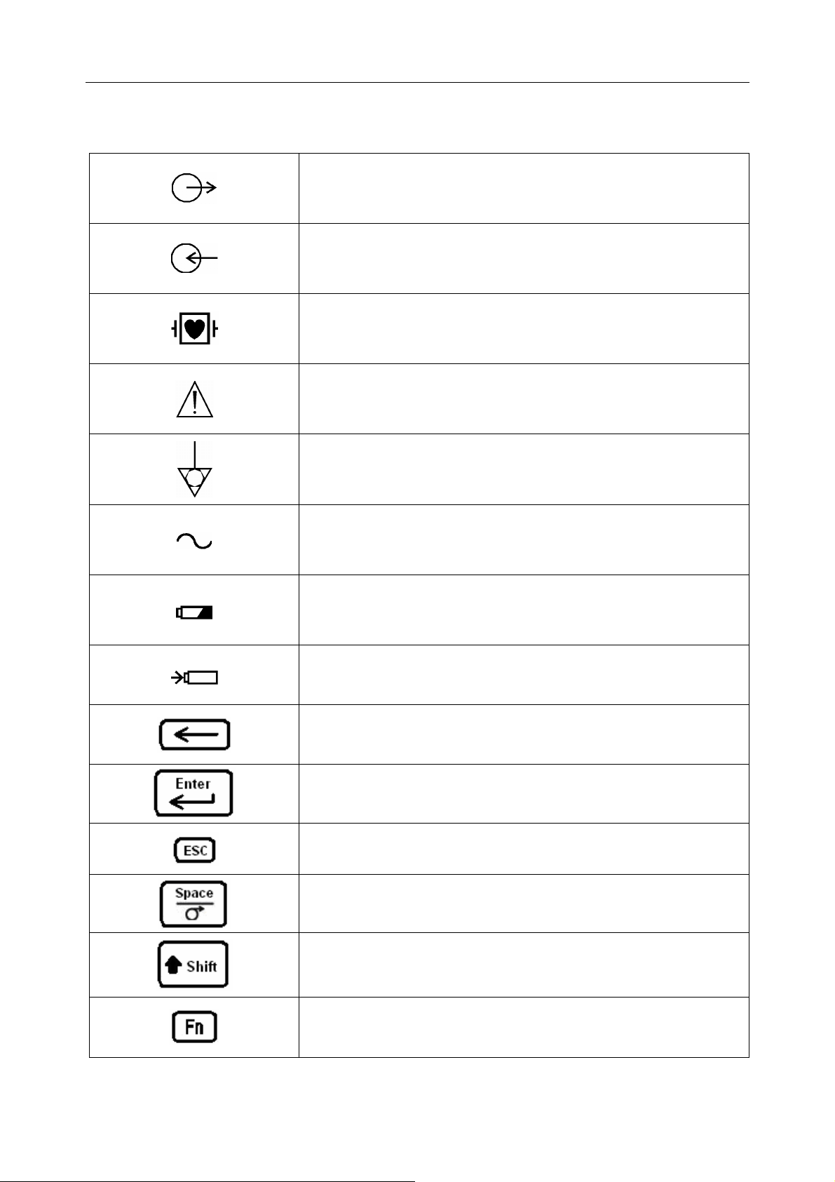
1.3 List of Symbols
External output
External input
Equipment or part of CF type with defibrillator proof
Attention – general warning (see accompanying document)
Potential equalization
Mains Supply
Battery indicator
Battery recharging indicator
Delete key
Enter key
Esc key
Space key/Feed paper key
Shift key
Fn key
- 5 -
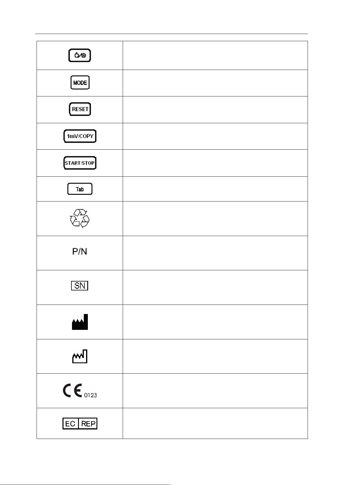
SE-601 Series Electrocardiograph User Manual
Power On/Off key
MODE key
RESET key
1mV/COPY key
START/STOP key
Tab key
Recycle
Part Number
Serial Number
Manufacturer
Date of Manufacture
The symbol indicates that the device complies with the
European Council Directive 93/42/EEC concerning medical
devices.
Authorized Representative in the European Community
- 6 -

SE-601 Series Electrocardiograph User Manual
The symbol indicates that the device should be sent to the
special agencies according to local regulations for separate
collection after its useful life and that this unit was put on
the market after 13 August 2005.
It indicates that the device should be sent to the special
agencies according to local regulations for separate
collection after its useful life
Rx only (U.S.)
Federal (U.S.) Law restricts this device to sale by or on the
order of a physician
- 7 -
SE-601 Series Electrocardiograph User Manual
Chapter 2 Introduction
The 6-channel electrocardiograph gathers ECG signals of 12 leads simultaneously. It displays
the operation menu, ECG parameters as well as electrocardiograms.
The 6-channel ECG waves can be viewed on the LCD screen and printed out by using a
high-quality thermal recorder.
The manual, auto, rhythm or R-R mode can be chosen freely.
SE-601 can be powered by the mains supply or a built-in rechargeable lithium battery.
With a high resolution thermal recorder, a 32-bit processor and a large-capacity memorizer, the
6-channel electrocardiograph has advanced performance and high reliability. The compact size
makes it suitable for clinic and hospital uses.
The 6-channel electrocardiograph has three models: SE-601A, SE-601B and SE-601C.
SE-601A adopts 192×64 dot single color LCD screen; SE-601B adopts 320×240 dot single
color LCD screen; SE-601C adopts 640×480 dot multicolor TFT LCD screen.
Configuration: main unit, power cord, patient cable, chest electrodes, limb electrodes,
disposable electrodes, alligator clips, thermal recorder paper, fuses and lithium
battery.
WARNING :
1. This equipment is intended for use on adult and pediatric patients only.
2. This equipment is not designed for internal use or direct cardiac application.
3. The results given by the equipment should be examined based on the overall
clinical condition of the patient, and they can not substitute for regular checking.
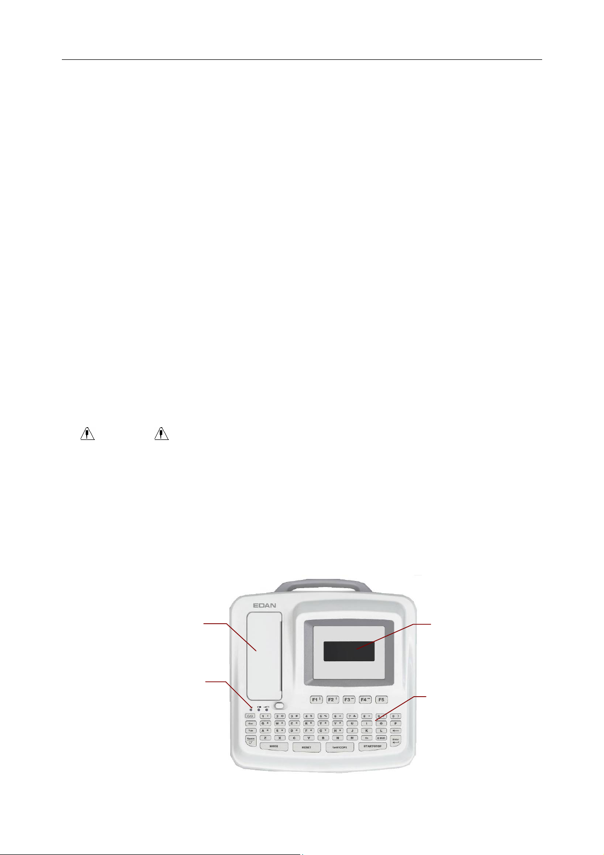
2.1 Top Panel
Recorder
LCD Screen
Indicators
From left to right on the
top panel: A, B, C.
Keyboard
Figure 2-1 SE-601A
- 8 -
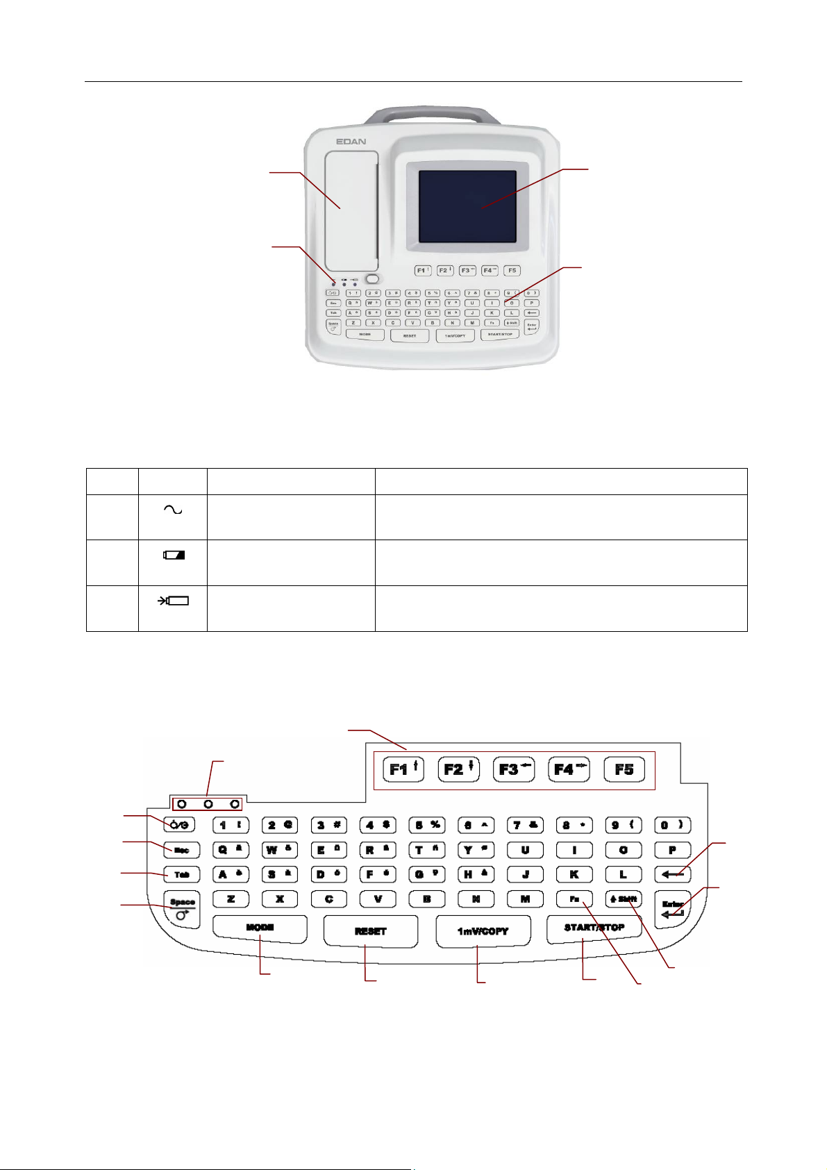
SE-601 Series Electrocardiograph User Manual
Recorder
Indicators
From left to right on
the top panel: A, B, C.
Figure 2-2 SE-601B / SE-601C
Indicator
Symbol Name Explanation
A
B
Mains supply
indicator
Battery indicator
When the device is powered by the mains supply,
this indicator is lit.
When the device is powered by the built-in
rechargeable lithium battery, this indicator is lit.
LCD Screen
Keyboard
C
Battery recharging
indicator
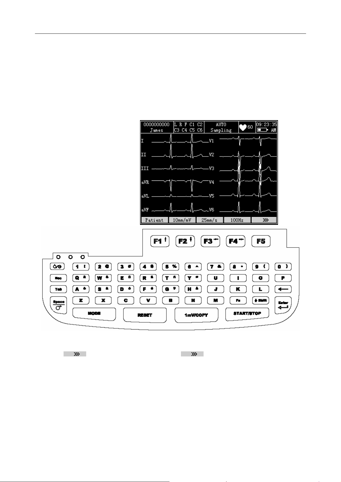
2.2 Keyboard and Keys
A
B (1, 2, 3)
C
D
E
F
G
Figure 2-3 SE-601A / SE-601B / SE-601C Keyboard
When the battery is being recharged, this indicator is
lit.
H
I
J
L
K
N
M
- 9 -
SE-601 Series Electrocardiograph User Manual
Name Explanation
A Function Key
Selecting menu functions on the screen (Pressing F1, F2, F3 or F4
can move the cursor)
1 indicates that the device is powered by the mains supply
B Indicator
2 indicates that the device is powered by the battery
3 indicates the battery charging status
C
Power on / off
D Esc Canceling operation
E Tab
Pressing Tab can move the cursor forward, and pressing Shift +
Tab can move the cursor backward.
Space: adding a space between typed characters
Feed Paper: before printing, if Paper Marker is set to Style1 or
F
Style2, you can press the Space key to advance the recorder paper
to the next paper marker; if Paper Marker is set to No, you can
press the Space key to advance the paper for about 2cm. Press the
Space key again to stop advancing the paper.
Press this key to select a working mode among AUTO, MANUAL
and RHYTHM.
G MODE
Note: Only on the Work Mode Setup interface can the R-R
mode be selected.
H RESET Draw the baseline to zero quickly in the case of baseline drift
In the AUTO mode, pressing the 1mV/Copy key can print the ECG
report which was printed out last time.
I 1mV/COPY
In the Manu mode, pressing the 1mV/Copy key can insert a 1mV
calibration mark in the printing course.
J START/STOP Start/Stop printing reports
K Fn Inputting special characters. Press Fn + a to type è.
L Shift Inputting a capital letter. Press Shift + p to type a capital P.
M Enter Confirming operation
N Delete Deleting characters
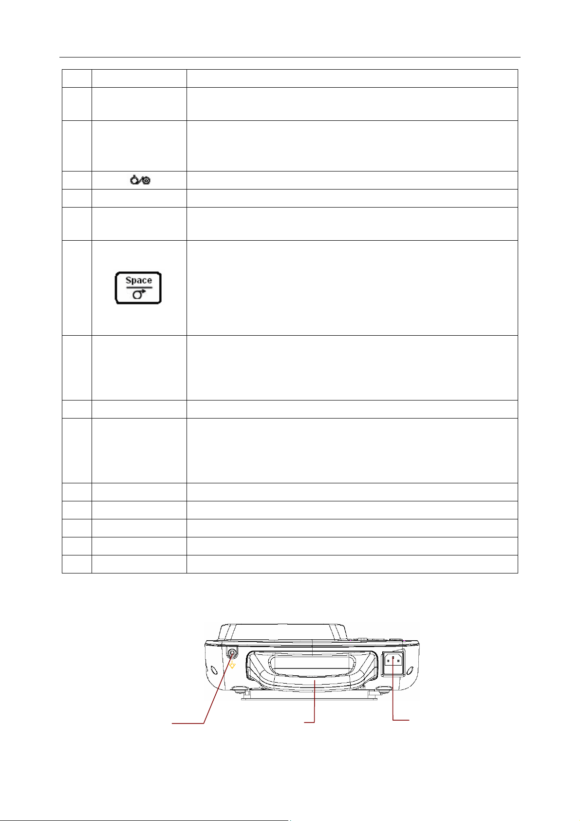
2.3 Rear Panel
A
Figure 2-4 SE-601A / SE-601B / SE-601C Rear Panel
B
- 10 -
C
SE-601 Series Electrocardiograph User Manual
Name Explanation
A
Potential Equalization
Potential equalization conductor provides a connection
between the unit and the potential equalization bus bar
of the electrical installation.
Conductor
B Handle Part for people to hold
C
Mains Supply Socket
AC SOURCE: alternating current supply socket
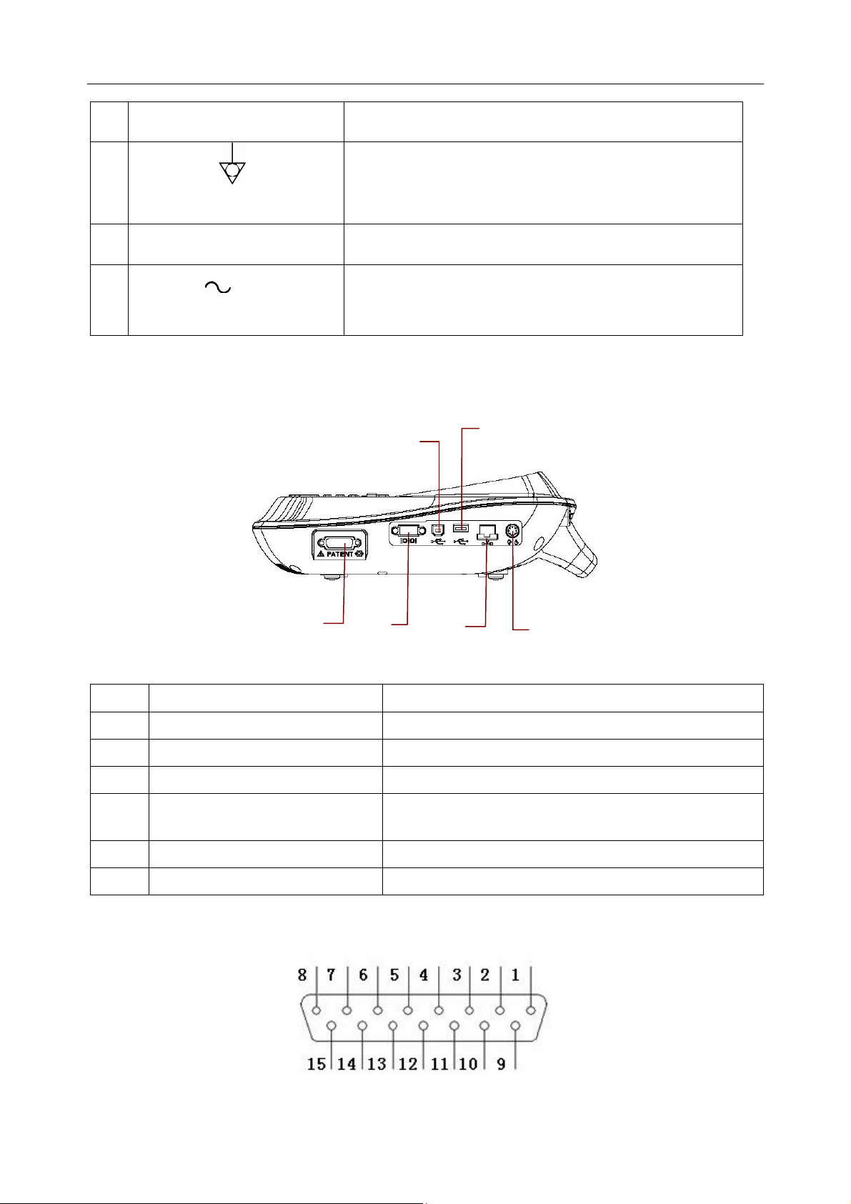
2.4 Right Panel
C
D
A
Figure 2-5 SE-601A / SE-601B / SE-601C Right Panel
B
E
F
Name Explanation
A Patient Cable Socket Connecting to the patient cable
B Serial Port 1 Connecting to a PC
C USB Socket 1 (Optional) Standard USB socket, connecting to a PC
D
USB Socket 2 (Optional)
Standard USB socket, connecting to a U disk or a
USB printer recommended by the manufacturer
E Net port Standard net port, connecting to a PC
F External Input / Output Socket Connecting to the external signal device
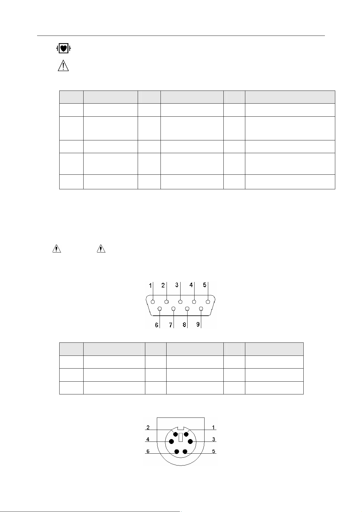
1) Patient Cable Socket
- 11 -
SE-601 Series Electrocardiograph User Manual
: Applied part of type CF with defibrillator proof
: Attention – see accompanying document
Definitions of corresponding pins:
Pin Signal Pin Signal Pin Signal
1
2
C2 / V2
C3 / V3
6
7
SH
NC
11
12
F / LL
C1 / V1
or NC
3
4
C4 / V4
C5 / V5
8
9
NC
R / RA
13
14
C1 / V1
RF (N) /RL
or NC
5
C6 / V6
10
L / LA
15
RF (N) / RL
Note: The left side of “/” is European standard; and the right side is American standard.
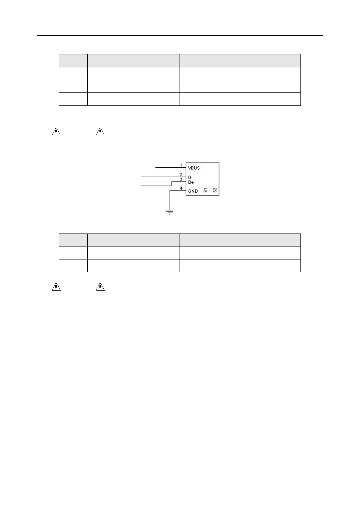
2) Serial Port 1
WARNING :
The isolated intensity of serial port 1 is 1500V AC and the maximum voltage
applied should not exceed +15V DC.
Definitions of corresponding pins:
Pin Signal Pin Signal Pin Signal
1
2
3
NC
RxD (input)
TxD (output)
3) External Input / Output Socket
4
5
6
- 12 -
NC
GND
NC
7
8
9
NC
NC
NC
SE-601 Series Electrocardiograph User Manual
Definitions of corresponding pins:
Pin Signal Pin Signal
1
2
3
GND
GND
GND
4) USB Socket 1 / USB Socket 2 (Optional)
WARNING : Only the USB equipment recommended by the manufacturer can
be connected to the USB interface.
Definitions of corresponding pins:
Pin Signal Pin Signal
4
5
6
GND
ECG Signal (input)
ECG Signal (output)
1
2
VBUS
D-
3
4
D+
GND
WARNING :
1. Accessory equipment connected to the analog and digital interfaces must be
certified according to the respective IEC/EN standards (e.g. IEC/EN 60950 for
data processing equipment and IEC/EN 60601-1 for medical equipment).
Furthermore all configuration shall comply with the valid version of the standard
IEC/EN 60601-1-1. Therefore anybody, who connects additional equipment to
the signal input or output connector to configure a medical system, must make
sure that it complies with the requirements of the valid version of the system
standard IEC/EN 60601-1-1. If in doubt, consult our technical service
department or your local distributor.
2. The summation of leakage current should never exceed leakage current limits
while several other units are used at the same time.
- 13 -
SE-601 Series Electrocardiograph User Manual
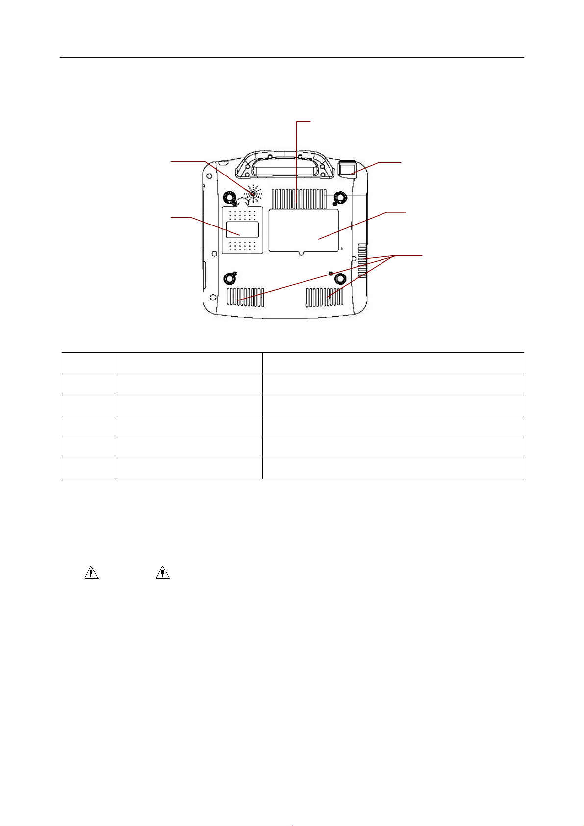
2.5 Bottom Panel
C
A
B
Figure 2-6 SE-601 A / SE-601B / SE-601C Bottom Panel
E
D
C
Name Explanation
A Speaker Hole Path for sound from speaker (Only for SE-601B/C)
B Battery Compartment Compartment for lithium battery
C Heat Emission Hole Path for internal heat emission
D Label Position for product information label
E Fuse The fuse specification is T1AL250VP Ø5×20.
1) Battery Compartment
The rated voltage and the rated capacity of the rechargeable lithium battery are as follows:
Rated Voltage: 14.8V; Rated Capacity: 2200mAh.
WARNING :
1. Improper operation may cause the battery to be hot, ignited or exploded, and it
may lead to the decrease of the battery capacity. Therefore, it is necessary to
read the user manual carefully and pay more attention to warning messages.
2. When leakage or foul smell is found, stop using the battery immediately. If your
skin or cloth comes into contact with the leakage liquid, cleanse it with clean
water at once. If the leakage liquid splashes into your eyes, do not wipe them.
Irrigate them with clean water first and go to see a doctor immediately.
3. Only qualified service engineers authorized by the manufacturer can open the
battery compartment and replace the battery, and batteries of the same model
- 14 -

SE-601 Series Electrocardiograph User Manual
and specification must be used.
4. Only when the device is off can the battery be installed or removed.
Note: If the battery has not been used for two months or more, you should recharge
it before using it again.
2) Fuse
There is a fuse installed on the bottom of the main unit. The specification is T1AL250VP
Ø5×20.
WARNING : Ruptured fuse must only be replaced with that of the same type
and rating as the original.
2.6 Function Features
♦ Low weight and compact size
♦ Multi-language support
♦ ECG signals of 12 leads are gathered and amplified simultaneously, 6-channel waves
are displayed and recorded simultaneously
♦ High resolution thermal recorder, recording frequency response ≤150Hz
♦ Flexible printing formats
♦ Full alphanumeric capability QWERTY keyboard
♦ The auto, manual, rhythm, and R-R modes are optional
♦ Convenient operation of system setup and file management
♦ Measurement function and interpretation function are optional
♦ Hint information of lead off, lack of paper and low battery capacity etc.
♦ Built-in rechargeable lithium battery with large capacity
♦ Automatic baseline adjustment for optimal printing
♦ Supporting real-time sampling, pre-sampling, period sampling and arrhythmia
triggering sampling
♦ LCD backlight and the device can be turned off automatically according to the set time
♦ The patient information to be printed is optional
- 15 -
SE-601 Series Electrocardiograph User Manual
Chapter 3 About SE-601 Application
The following sections provide an overview of the main operations and functions in the SE-601
application.
3.1 Selecting Menu Functions
To select Patient, press the function key F1 below Patient.
To select
, press the function key F5 below .
- 16 -
SE-601 Series Electrocardiograph User Manual
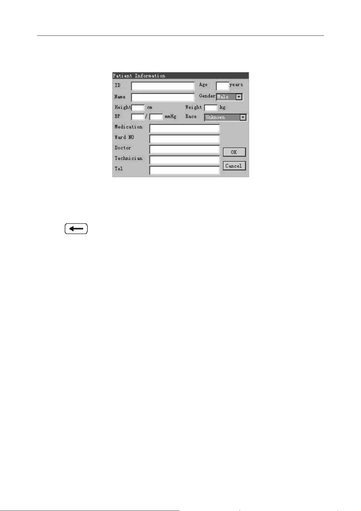
3.2 Entering Data
1. When the main interface1 is displayed, press the function key F1 below Patient to open the
Patient Information window.
2. Press Tab or Shift + Tab to move the cursor to the Name textbox.
3. Press on the keyboard to erase the typed information.
4. Press the letter or number keys on the keyboard to input patient name. Press Fn and a letter key
to input the special character in the top right corner of the key. Press Shift and a number key to
input the special character in the top right corner of the key. Press Shift and a letter key to input a
capital letter. For example, press Fn + a to input è, press Shift + 3 to input #, and press Shift + a
to input a capital A.
5. Press Enter to confirm, or press Tab or Shift + Tab to move the cursor to the OK button, and
then press Enter to confirm.
6. Press Esc to cancel the operation, or press Tab or Shift + Tab to move the cursor to the Cancel
button, and then press Enter to cancel the operation.
- 17 -
SE-601 Series Electrocardiograph User Manual
3.3 Selecting an Option from a List
For SE-601B/C
1. Press Tab or Shift + Tab to move the cursor to the Work Mode item.
2. Press F1 or F2 to select MANU, AUTO, RHTY or R-R.
3. Press Enter to confirm, or press Tab or Shift + Tab to move the cursor to the OK button, and
then press Enter to confirm.
4. Press Esc to cancel the operation, or press Tab or Shift + Tab to move the cursor to the Cancel
button, and then press Enter to cancel the operation.
For SE-601A
1. Press F1, F2, Tab or Shift + Tab to move the cursor to the Work Mode item.
2. Press F3 or F4 to select MANU, AUTO, RHTY or R-R.
3. After setup, press Enter to confirm, or press Esc to display a hint to prompt you to save these
modifications.
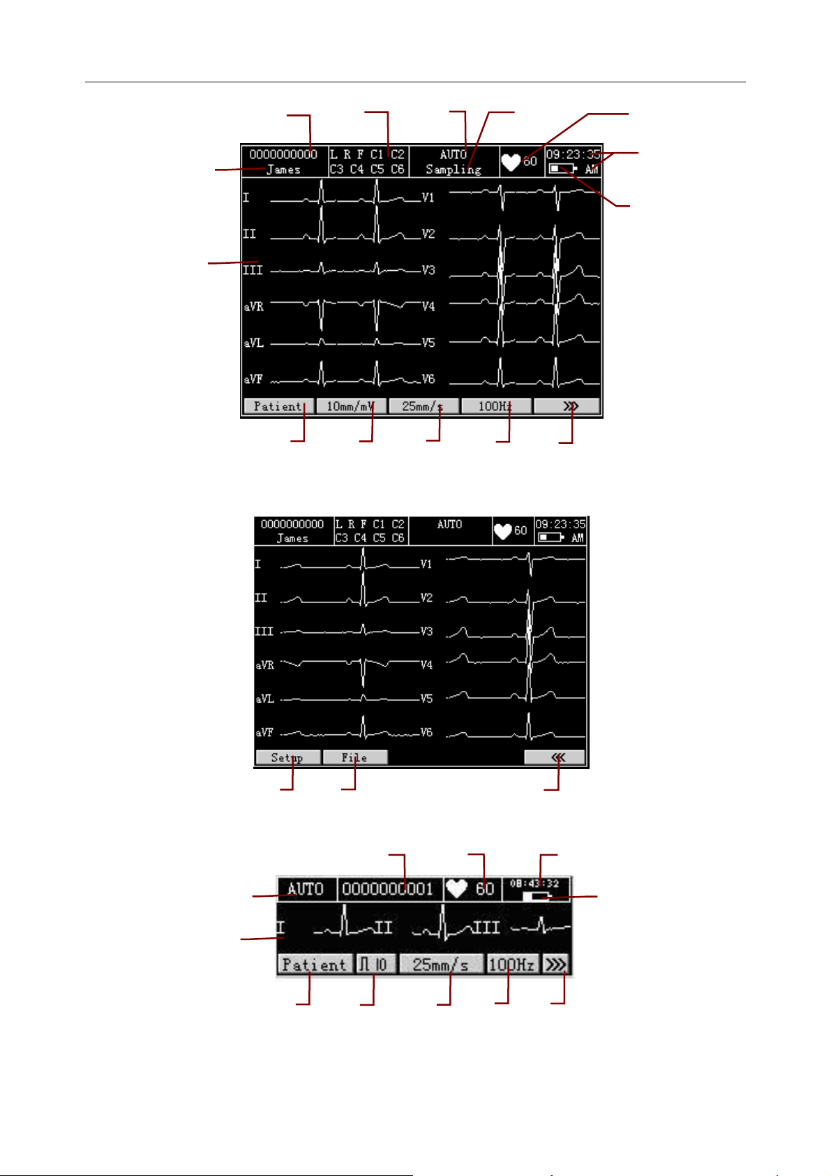
3.4 About the Main Interface
After you turn on the device, the main interface1 pops up. Press the function key F5 below
to open the main interface2.
- 18 -
SE-601 Series Electrocardiograph User Manual
M
A
B
L
Figure 3-1 SE-601B / SE-601C Main Interface1
C
K
D
J
I
C
H
E
F
G
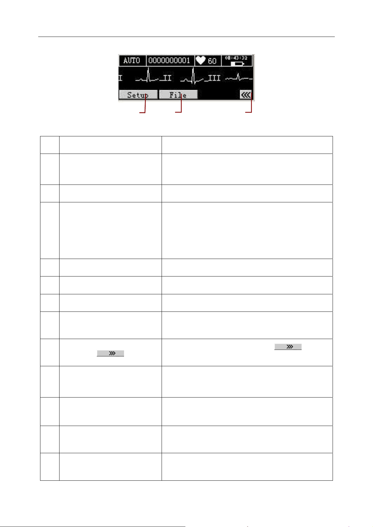
M
P
Figure 3-2 SE-601B / SE-601C Main Interface2
D
L
O
E
K
Figure 3-3 SE-601A Main Interface1
J
- 19 -
I
N
F B
G
H
SE-601 Series Electrocardiograph User Manual
P
Figure 3-4 SE-601A Main Interface2
O
N
Name Explanation
A Name Patient Name: within 12 characters (for SE-601B/C)
within 10 characters (for SE-601A)
B ID Patient ID: within 10 characters
C
Including Lead Off, No Paper, Paper Error, Battery
Weak, Modu Error, Demo, Sampling, Analyzing,
Hint Information
Recording, Learning, Transmitting, Transmit Fail,
Detecting, Memory Full, Overload, U Disk, USB
Printer, Testing
D Work Mode MANU, AUTO, RHYT or R-R
E Heart Rate Actual Heart Rate
F Current Time Refer to Section 9.8, “Date & Time Setup”
G
H
I
Battery Symbol
Identify the current capacity of the rechargeable
battery
Press the function key F5 below to open
the main interface2
EMG Filter: 25Hz, 35Hz or 45Hz
100Hz
Lowpass Filter: 75Hz, 100Hz or 150Hz
J
25mm/s
Paper Speed: 5 mm/s, 6.25 mm/s、10 mm/s, 12.5
mm/s, 25 mm/s or 50mm/s
K
L
10mm/mV
Patient
Gain: 10 mm/mV, 20 mm/mV, 10/5 mm/mV, AGC,
2.5 mm/mV or 5 mm/mV
Press the function key F1 below Patient to display
the Patient Information window
- 20 -
SE-601 Series Electrocardiograph User Manual
M ECG waveform Display ECG waveform
N
O
File
Press the function key F5 below to return to
the main interface1
Press the function key F2 below File to open the File
Manage interface. For details, please refer to Chapter
8, “Managing Files”.
P
Setup
Press the function key F1 below Setup to display the
System Setup interface. For details, please refer to
Chapter 9, “System Setup”.
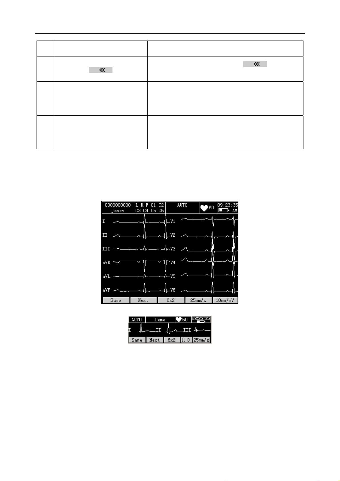
To Open the Main Interface3
If Next Patient is set to On, in the AUTO mode, press the START/STOP key to print ECG
reports, and the system will automatically open the main interface3 after a complete ECG report
is printed.
Figure 3-5 SE-601B / SE-601C Main Interface3
Figure 3-6 SE-601A Main Interface3
On the main interface3, pressing the function key F1 below Same can return to the main
interface1, and all the patient information will keep the same; pressing the function key F2 below
Next can return to the main interface1, all the patient information will be cleared, and patient ID
will be refreshed.
On the main interface3, you can print the previous ECG report again according to the set style,
paper speed and gain which are shown on the bottom of the interface. Pressing the function key
F3 can switch the auto style, pressing the function key F4 can switch the paper speed, and
- 21 -
SE-601 Series Electrocardiograph User Manual
pressing the function key F5 can switch the gain.
To Select the Next Patient Function
When the main interface2 is displayed, press the function key F1 below Setup to open the
System Setup interface.
Press F1, F2, F3, F4, Ta b or Shift + Ta b to move the cursor to Pat. Question on the System
Setup interface, and then press Enter to open the Patient Question interface.
For SE-601B/C, press Tab or Shift + Tab to move the cursor to the Next Patient item, and then
press F1 or F2 to select On.
For SE-601A, press F1, F2, Tab or Shift + Tab to move the cursor to the Next Patient item, and
then press F3 or F4 to select On.
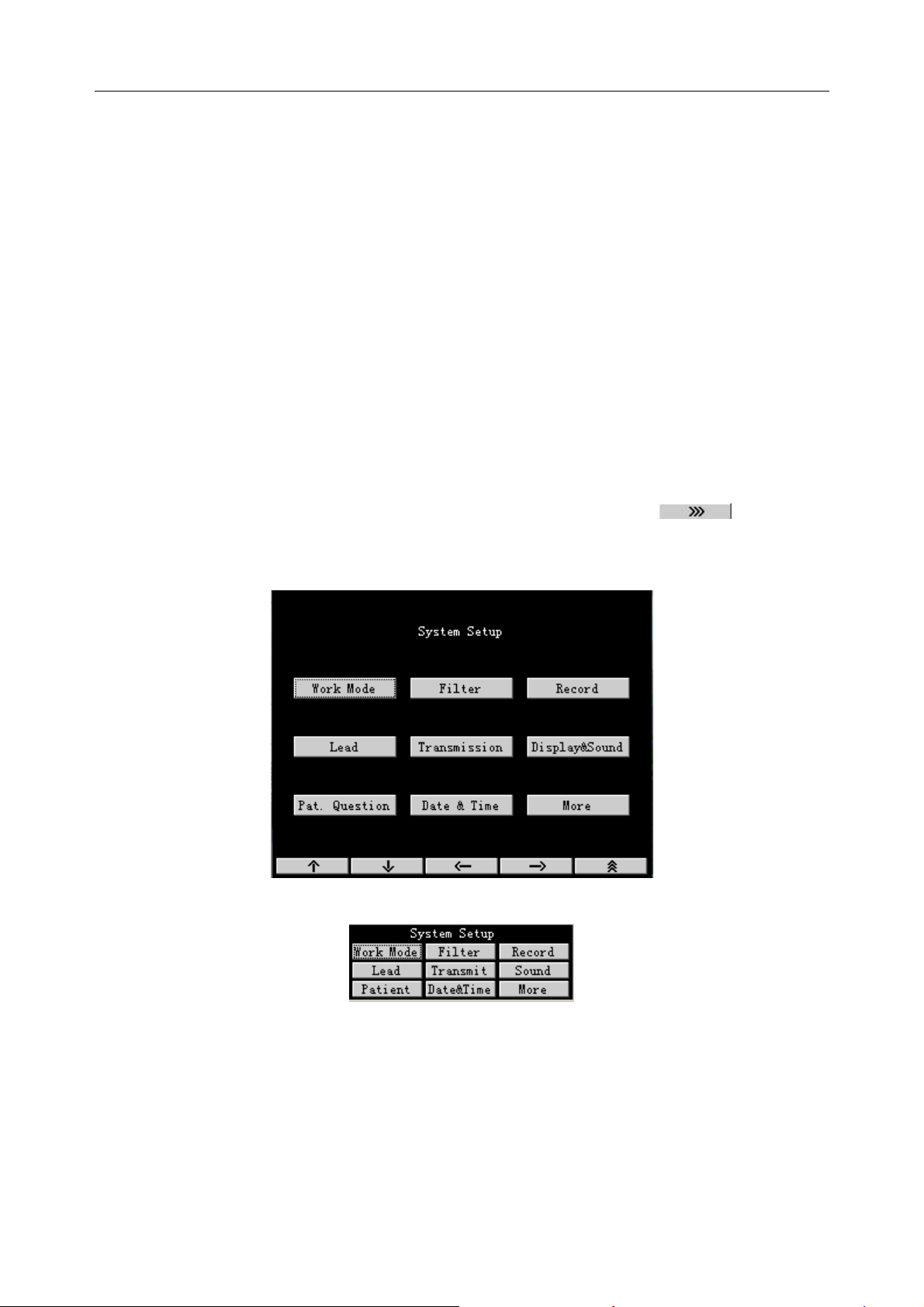
3.5 About the System Setup Interface
When the main interface1 is displayed, press the function key F5 below to open the
main interface2. When the main interface2 is displayed, press the function key F1 below Setup to
open the System Setup interface.
Figure 3-7 SE-601B / SE-601C System Setup Interface
Figure 3-8 SE-601A System Setup Interface
On the System Setup interface, press F1, F2, F3, F4, Ta b or Shift + Tab to move the cursor to a
button, and then press Enter to open the setup interface related to the button.
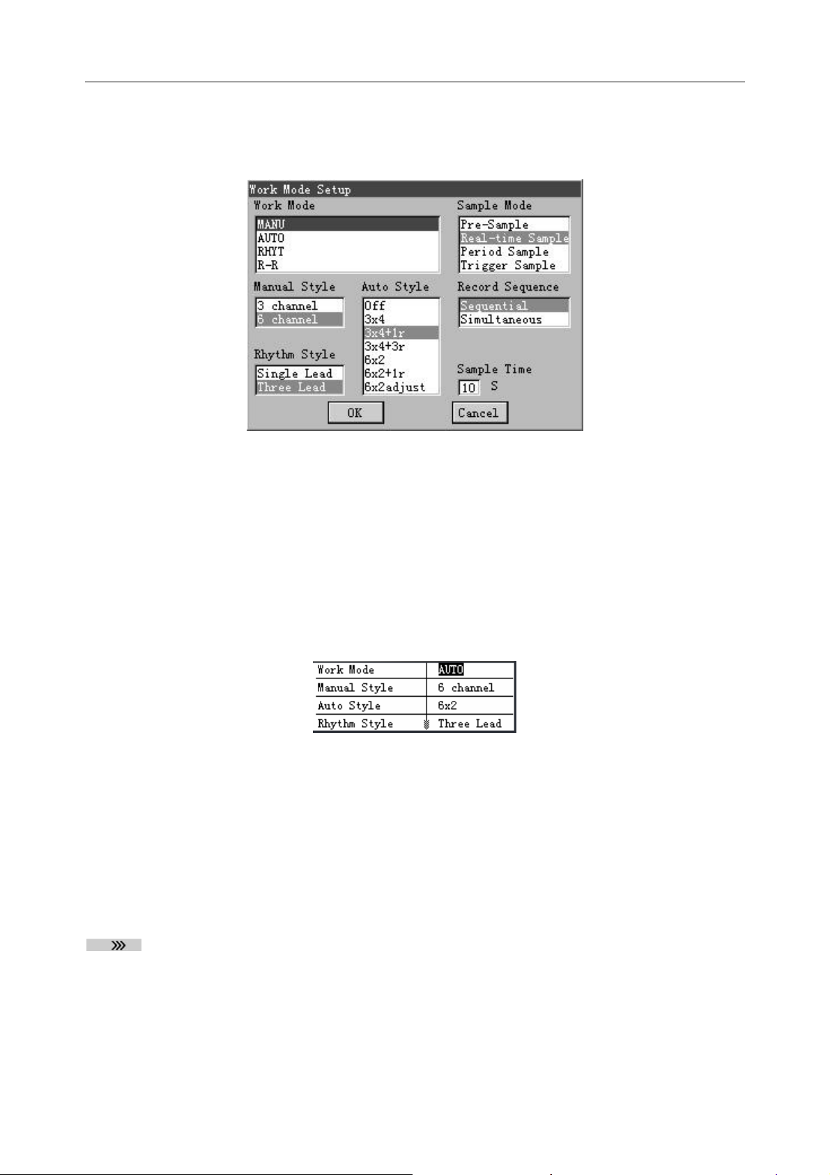
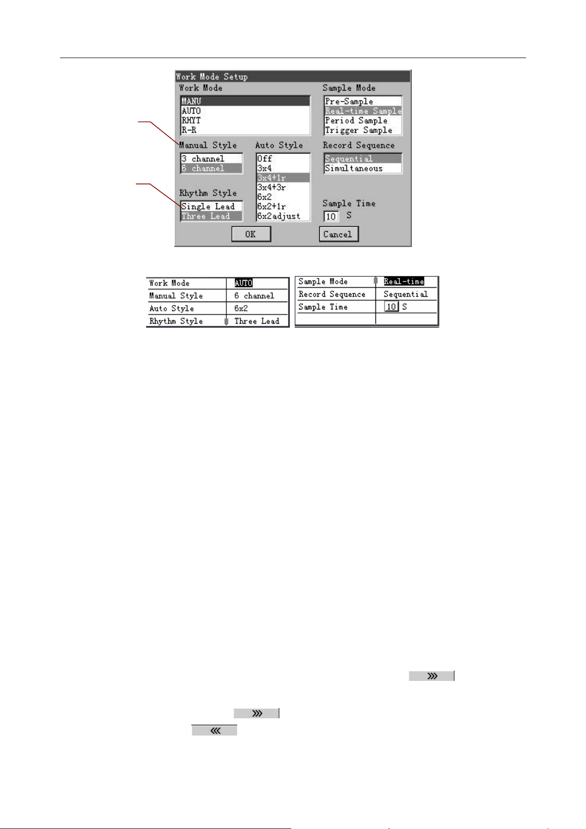
Take the Work Mode Setup interface for example:
On the System Setup interface, press F1, F2, F3, F4, Ta b or Shift + Ta b to move the cursor.
When the cursor is on Work Mode, press Enter to display the Work Mode Setup interface.
- 22 -
Item
Option
SE-601 Series Electrocardiograph User Manual
Figure 3-9 SE-601B / SE-601C Work Mode Setup Interface
Figure 3-10 SE-601A Work Mode Setup Interface
For SE-601B/C
1. On the Work Mode Setup interface, press Tab or Shift + Tab to move the cursor among
different setup menus.
2. Press F1 or F2 to select an option in a setup menu.
3. Press Enter to confirm, or press Tab or Shift + Tab to move the cursor to the OK button, and
then press Enter to confirm.
4. Press Esc to cancel the operation, or press Tab or Shift + Tab to move the cursor to the Cancel
button, and then press Enter to cancel the operation.
For SE-601A
1. On the Work Mode Setup interface, press F1, F2, Tab or Shift + Tab to move the cursor
among different setup menus.
2. Press F3 or F4 to select an option in a setup menu.
3. Press Enter to confirm, or press Esc to display a hint to prompt you to save these
modifications.
3.6 About the File Manage Interface
When the main interface1 is displayed, press the function key F5 below to display the
main interface2. Press the function key F2 below File to open the File Manage interface1.
1. Press the function key F5 below to display the File Manage interface2. Then press
the function key F5 below to return to the File Manage interface1.
2. Or press F1, F2, Shift + F1 or Shift + F2 to highlight a file on the File Manage interface1,
- 23 -
 Loading...