


Preface
Copyright
This publication, including all photographs, illustrations and software, is protected under
international copyright laws, with all rights reserved. Neither this manual, nor any of the
material contained herein, may be reproduced without written consent of the author.
Version 1.0
Disclaimer
The information in this document is subject to change without notice. The manufacturer
makes no representations or warranties with respect to the contents hereof and specifically
disclaims any implied warranties of merchantability or fitness for any particular purpose.
The manufacturer reserves the right to revise this publication and to make changes from
time to time in the content hereof without obligation of the manufacturer to notify any
person of such revision or changes.
Trademark Recognition
Microsoft, MS-DOS and Windows are registered trademarks of Microsoft Corp.
MMX, Pentium, Pentium-II, Pentium-III, Celeron are registered trademarks of Intel Cor-
poration.
Other product names used in this manual are the properties of their respective owners and
are acknowledged.
Federal Communications Commission (FCC)
This equipment has been tested and found to comply with the limits for a Class B digital
device, pursuant to Part 15 of the FCC Rules. These limits are designed to provide reasonable protection against harmful interference in a residential installation. This equipment
generates, uses, and can radiate radio frequency energy and, if not installed and used in
accordance with the instructions, may cause harmful interference to radio communications.
However, there is no guarantee that interference will not occur in a particular installation.
If this equipment does cause harmful interference to radio or television reception, which
can be determined by turning the equipment off and on, the user is encouraged to try to
correct the interference by one or more of the following measures:
• Reorient or relocate the receiving antenna
• Increase the separation between the equipment and the receiver
• Connect the equipment onto an outlet on a circuit different from that to which
the receiver is connected
• Consult the dealer or an experienced radio/TV technician for help
Shielded interconnect cables and a shielded AC power cable must be employed with this
equipment to ensure compliance with the pertinent RF emission limits governing this
device. Changes or modifications not expressly approved by the system’s manufacturer
could void the user’s authority to operate the equipment.
Preface

ii
Declaration of Conformity
This device complies with part 15 of the FCC rules. Operation is subject to the following
conditions:
• This device may not cause harmful interference, and
• This device must accept any interference received, including interference
that may cause undesired operation
Canadian Department of Communications
This class B digital apparatus meets all requirements of the Canadian Interference-causing
Equipment Regulations.
Cet appareil numérique de la classe B respecte toutes les exigences du Réglement sur le
matériel brouilieur du Canada.
About the Manual
The manual consists of the following:
Chapter 1
Introducing the Motherboard
Describes features of the motherboard.
Go to
H
page 1
Chapter 2
Installing the Motherboard
Chapter 3
Using BIOS
Chapter 4
Using the Motherboard Software
Describes installation of motherboard
components.
Go to
Provides information on using the BIOS
Setup Utility.
Go to
Describes the motherboard software
Go to
H
H
H
page 7
page 27
page 49
Preface

TT
ABLE OF CONTENTSABLE OF CONTENTS
T
ABLE OF CONTENTS
TT
ABLE OF CONTENTSABLE OF CONTENTS
Preface i
iii
Chapter 1
Introducing the Motherboard 1
Introduction.................................................................................................1
Feature..........................................................................................................2
Motherboard Components........................................................................4
1
Chapter 2
Installing the Motherboard 7
Safety Precautions......................................................................................7
Choosing a Computer Case.......................................................................7
Installing the Motherboard in a Case......................................................7
Checking Jumper Settings.........................................................................8
Setting Jumpers..............................................................................8
Checking Jumper Settings..............................................................9
Jumper Settings..............................................................................9
Connecting Case Components...............................................................10
Front Panel Connector.................................................................12
Installing Hardware...................................................................................13
Installing the Processor...............................................................13
Installing Memory Modules.........................................................15
Installing a Hard Disk Drive/CD-ROM/SATA Hard Drive........17
Installing a Floppy Diskette Drive...............................................18
Installing Add-on Cards..............................................................20
Connecting Optional Devices......................................................23
Connecting I/O Devices..........................................................................26
7 7
7
7 7
Chapter 3
Using BIOS 27
About the Setup Utility............................................................................27
Using BIOS................................................................................................29
27 27
27
27 27
The Standard Configuration........................................................27
Entering the Setup Utility..............................................................27
Updating the BIOS.......................................................................29
Standard CMOS Features...........................................................30
Advanced BIOS Features.............................................................32
Advanced Chipset Features.........................................................35

iv
Integrated Peripherals.................................................................38
Power Management Setup...........................................................42
PNP/PCI Configurations.............................................................44
PC Health Status..........................................................................45
Frequency/Voltage Contr ol..........................................................46
Load Fail-Safe Defaults Option...................................................47
Load Optimized Defaults Option.................................................47
Set Supervisor/User Password....................................................47
Save & Exit Setup Option.............................................................48
Exit Without Saving......................................................................48
Chapter 4
49 49
49
49 49
Using the Motherboard Software 49
About the Software CD-ROM................................................................49
Auto-installing under Windows 98/ME/2000/XP................................49
Running Setup..............................................................................50
Manual Installation..................................................................................52
Utility Software Reference.......................................................................52
Multi-Language Translation

Chapter 1
Introducing the Motherboard
Introduction
Thank you for choosing the RS400-A motherboard. This motherboard is a high performance, enhanced function motherboard that supports LGA775 Pentium 4/Celeron processors for high-end business or personal desktop markets.
The motherboard incorporates the RS400 Northbridge (NB) and SB400 Southbridge (SB)
chipsets. The Northbridge supports a Front Side Bus (FSB) frequency of 800/533 MHz using
a scalable FSB Vcc_CPU. The memory controller supports DDR/DDR2 SDRAM interface
of DDR400/333/266 MHz or DDR2-667/533/400 MHz. It supports four DDR Sockets with
up to maximum memory size of 2GB. Aside from the onboard AGP Express slot, one PCI
Express x16 slot, intended for Graphics Interface, is fully compliant to the PCI Express
Base Specification revision 1.0a.
The SB400 Southbridge supports two PCI slots which are PCI 2.3 compliant. In addition,
two PCI Express x1 slots are supported, fully compliant to the PCI Express Base Specification, Revision 1.0a. It implements an EHCI compliant interface that provides 480Mb/s
bandwidth for eight USB 2.0 ports. Two onboard IDE connectors supports 4 IDE devices in
UDMA 133/100/66/33 modes. The Southbridge integrates a Serial ATA host controller that
is SATA v1.0 compliant, supporting four SATA ports with maximum transfer rate up to 150
MB/s each.
The RS400-A motherboard is equipped with advanced full set of I/O ports in the rear panel,
including PS/2 mouse and keyboard connectors, COM1, LPT1, VGA, four USB ports, one
optional LAN port, and audio jacks for microphone, line-in and line-out.
1
Introducing the Motherboard

2
Feature
Processor
The RS400-A uses an LGA775 type of Pentium 4 that carries the following features:
• Accommodates the latest Intel P4/Celeron processors
• Supports a system bus (FSB) of 800/533MHz
• Supports “Hyper-Threading” technology CPU
“Hyper-Threading” technology enables the operating system into thinking it’s hooked
up to two processors, allowing two threads to be run in parallel, both on separate
“logical” processors within the same physical processor.
Chipset
The RS400 Northbridge (NB) and SB400 Southbridge (SB) chipsets are based on an
innovative and scalable architecture with proven reliability and performance.
RS400 (NB)
• Supports 128-bit dual-channel DDR/DDR2 SDRAM interface
• 1 x2 (expandable to x4) A-Link Express interface (PCI Express 1.0a compliant) for connection to the ATI IXP
• Supports one PCI Express x16 for Graphics Interface, fully
compliant to the PCI Express Base Specification revision
1.0a.
• Supports up to four x1 PCI Express for general purpose
links
• Supports 64, 128, 256, 512 Mb, and 1Gb system memory,
with x8, x16, and x32 memory device width
SB400 (SB) • 2-lane A-Link Express interface (PCI Express 1.0a compli-
ant) to RADEON IGPs
• Compliant with PCI 2.3 specificaiton, up to 7 bus master
devices supported
• Compliant with Serial ATA 1.0 specification, RAID 0 and
RAID 1 support
• Integrated USB 2.0 Host Controller supporting up to eight
USB 2.0 ports
• Integrated IDE controller supports Ultra DMA 133/100/66/33
modes
Memory
• Supports DDR 400/333/266 or DDR2 667/533/400 DDR SDRAM
• Accommodates four unbuffered DIMMs
• Up to 1GB per DIMM with maximum memory size up to 2GB
Users please note that DDR & DDR2 can’t both be applied at the same time on
this motherboard. Users can use either DDR or DDR2 memory modules only!
Audio
• Compliant with AC’97 2.3 specification
• 16-bit Stereo full-duplex CODEC with 48KHz sampling rate
• High quality differential CD input
• Supports double sampling rate (96KHz) of DVD audio playback
• Digital 48KHz of S/PDIF OUT & IN support
• Direct Sound 3D
TM
compatible
Introducing the Motherboard

Onboard LAN (Optional)
The onboard LAN controller provides the following features:
• Support 10/100/1000 Mbps N-way Auto-negotiation operation
• Supports Wake-On-LAN function and remote wake-up
• Supports LED pins for various network activity indications
• Supports Full Duplex Flow Control (IEEE 802.3x)
Expansion Options
The motherboard comes with the following expansion options:
• One PCI Express x16 for Graphic Interface
• Two PCI Express x1
• One AGP Express slot
• Two 32-bit PCI v2.3 compliant slots
• Two 40-pin IDE connectors supporting up to 4 IDE devices
• One floppy disk drive interface
• Four 7-pin SATA connector
The RS400-A motherboard supports UltraDMA bus mastering with transfer rates of
133/100/66/33 MB/s.
Integrated I/O
The motherboard has a full set of I/O ports and connectors:
• Two PS/2 ports for mouse and keyboard
• One serial port
• One parallel port
• One VGA port
• One 1394a port (optional)
• One LAN port (optional)
• Audio jacks for microphone, line-in and line-out
3
BIOS Firmware
This motherboard uses AWARD BIOS that enables users to configure many system
features including the following:
• Power management
• Wake-up alarms
• CPU parameters
• CPU and memroy timing
The firmware can also be used to set parameters for different processor clock speeds.
Some hardware specifications and software items are subject to change
with out prior notice.
Introducing the Motherboard
4
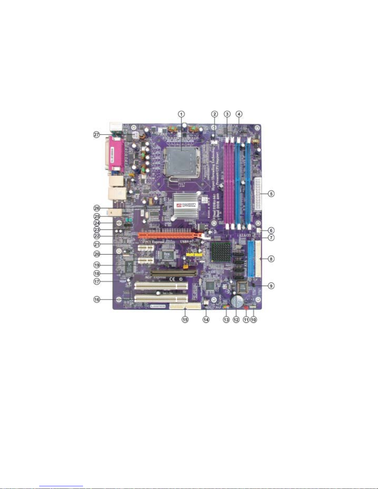
Motherboard Components
Introducing the Motherboard

Table of Motherboard Components
LABEL COMPONENT
1 CPU Socket LGA775 socket for Pentium 4/Celeron CPU
2 CPU_FAN CPU cooling fan connector
3 DIMM1~2 240-pin DDR2 SDRAM slots
4 DIMM3~4 184-pin DDR SDRAM slots
5 ATX_POWER Standard 24-pin ATX power connector
6 PWR_FAN Power fan connector
7 IDE1 Primary IDE channel
8 IDE2 Secondary IDE channel
9 BIOS_WP BIOS protection jumper
10 SPK1 Speaker header
11 CLR_CMOS Clear CMOS jumper
12 SATA1~4 Serial ATA connectors
13 PANEL1 Front panel switch/LED header
14 SYS_FAN System cooling fan connector
15 FDD Floppy diskette drive connector
16 PCI1~2 32-bit add-on card slots
17 SPDIFO1 SPDIF out header
18 AGP AGP Express slot
19 IR1 Infrared header
20 PCIE1~2 PCI Express x1 slots
21 USB3-4 Front Panel USB headers
22 PCIEX16 PCI Express x16 graphics card slot
23 AUX_IN* Auxliary-in header
24 CD_IN Analog audio input connector
25 AUDIO1 Front panel audio header
26 TV_OUT* TV-out header
27 ATX12V 4-pin +12V power connector
5
“*” stands for optional components and may not exist onboard.
Users please note that DDR & DDR2 can’t both be applied at the same time on
this motherboard. Users can use either DDR or DDR2 memory modules only!
This concludes Chapter 1. The next chapter explains how to install the motherboard.
Introducing the Motherboard

6
Memo
Introducing the Motherboard

Chapter 2
Installing the Motherboard
Safety Precautions
• Follow these safety precautions when installing the motherboard
• Wear a grounding strap attached to a grounded device to avoid damage from
static electricity
• Discharge static electricity by touching the metal case of a safely grounded
object before working on the motherboard
• Leave components in the static-proof bags they came in
• Hold all circuit boards by the edges. Do not bend circuit boards
Choosing a Computer Case
There are many types of computer cases on the market. The motherboard complies with
the specifications for the ATX system case. First, some features on the motherboard are
implemented by cabling connectors on the motherboard to indicators and switches on the
system case. Make sure that your case supports all the features required. Secondly, RS400A supports one or two floppy diskette drives and four enhanced IDE drives. Make sure that
your case has sufficient power and space for all drives that you intend to install.
Most cases have a choice of I/O templates in the rear panel. Make sure that the I/O
template in the case matches the I/O ports installed on the rear edge of the motherboard.
This motherboard carries a ATX form factor of 305 x 244 mm. Choose a case that
accommodates this form factor.
7
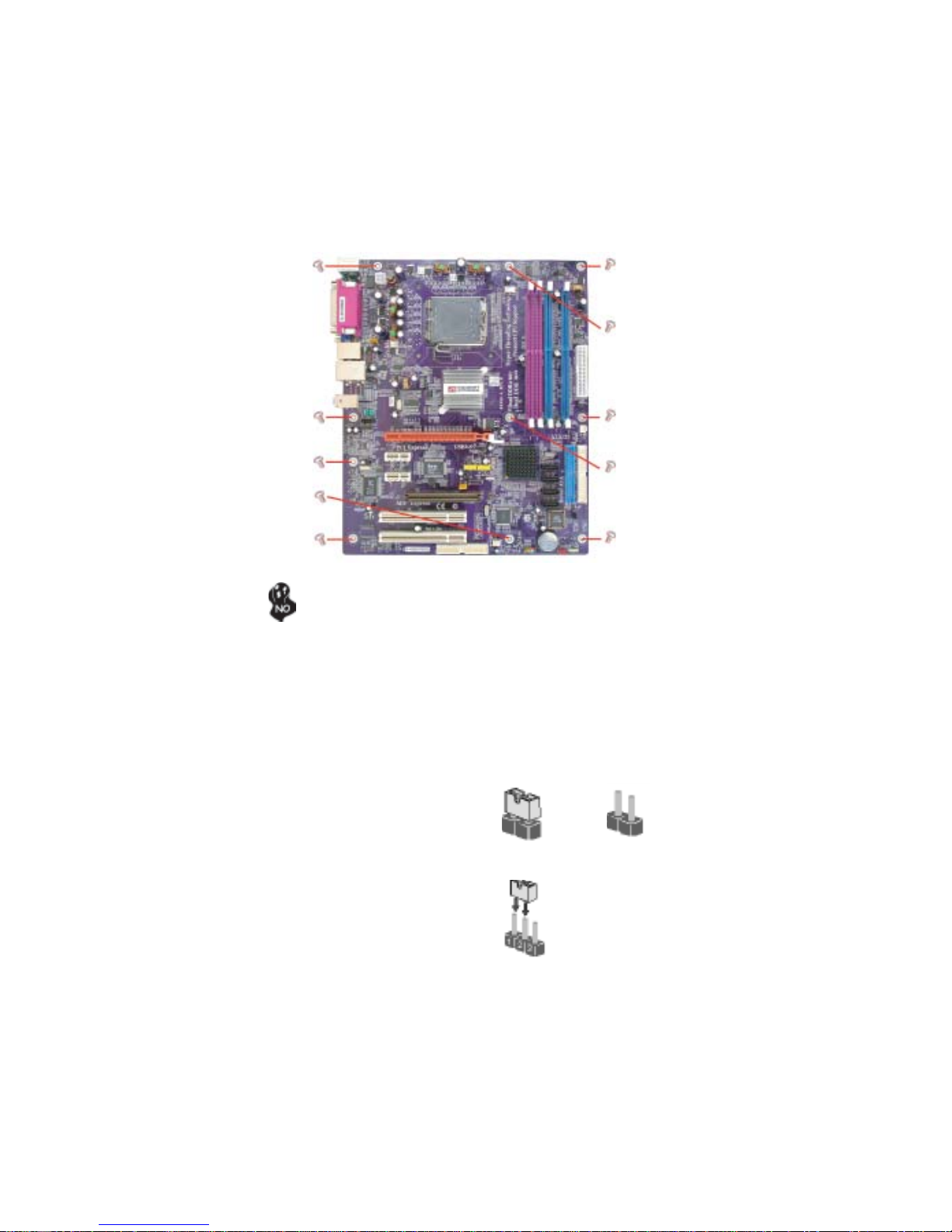
Installing the Motherboard in a Case
Refer to the following illustration and instructions for installing the motherboard in a case.
Most system cases have mounting brackets installed in the case, which correspond the holes
in the motherboard. Place the motherboard over the mounting brackets and secure the
motherboard onto the mounting brackets with screws.
Ensure that your case has an I/O template that supports the I/O ports and expansion slots
on your motherboard.
Installing the Motherboard
8
Do not over-tighten the screws as this can stress the motherboard.
Checking Jumper Settings
This section explains how to set jumpers for correct configuration of the motherboard.
Setting Jumpers
Use the motherboard jumpers to set system configuration options. Jumpers with more than
one pin are numbered. When setting the jumpers, ensure that the jumper caps are placed on
the correct pins.
The illustrations show a 2-pin jumper. When
the jumper cap is placed on both pins, the
jumper is SHORT. If you remove the jumper
cap, or place the jumper cap on just one pin,
the jumper is OPEN.
This illustration shows a 3-pin jumper. Pins
1 and 2 are SHORT
SHORT OPEN
Installing the Motherboard
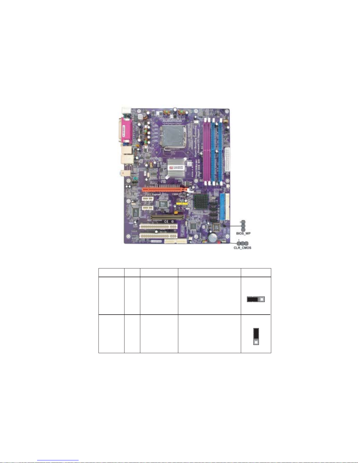
Checking Jumper Settings
The following illustration shows the location of the motherboard jumpers. Pin 1 is labeled.
9
Jumper Settings
Jumper
CLR_CMOS
BIOS_WP 3-pin
Type
3-pin
Description
CLEAR CMOS
BIOS PROTECT
Setting (default)
1-2: NORMAL
2-3: CMOS CLEAR
Before clearing the
CMOS, make sure to
turn off the system.
1-2: DISABLE
2-3: ENABLE
Installing the Motherboard
CLR_CMOS
1
BIOS_WP
1
10
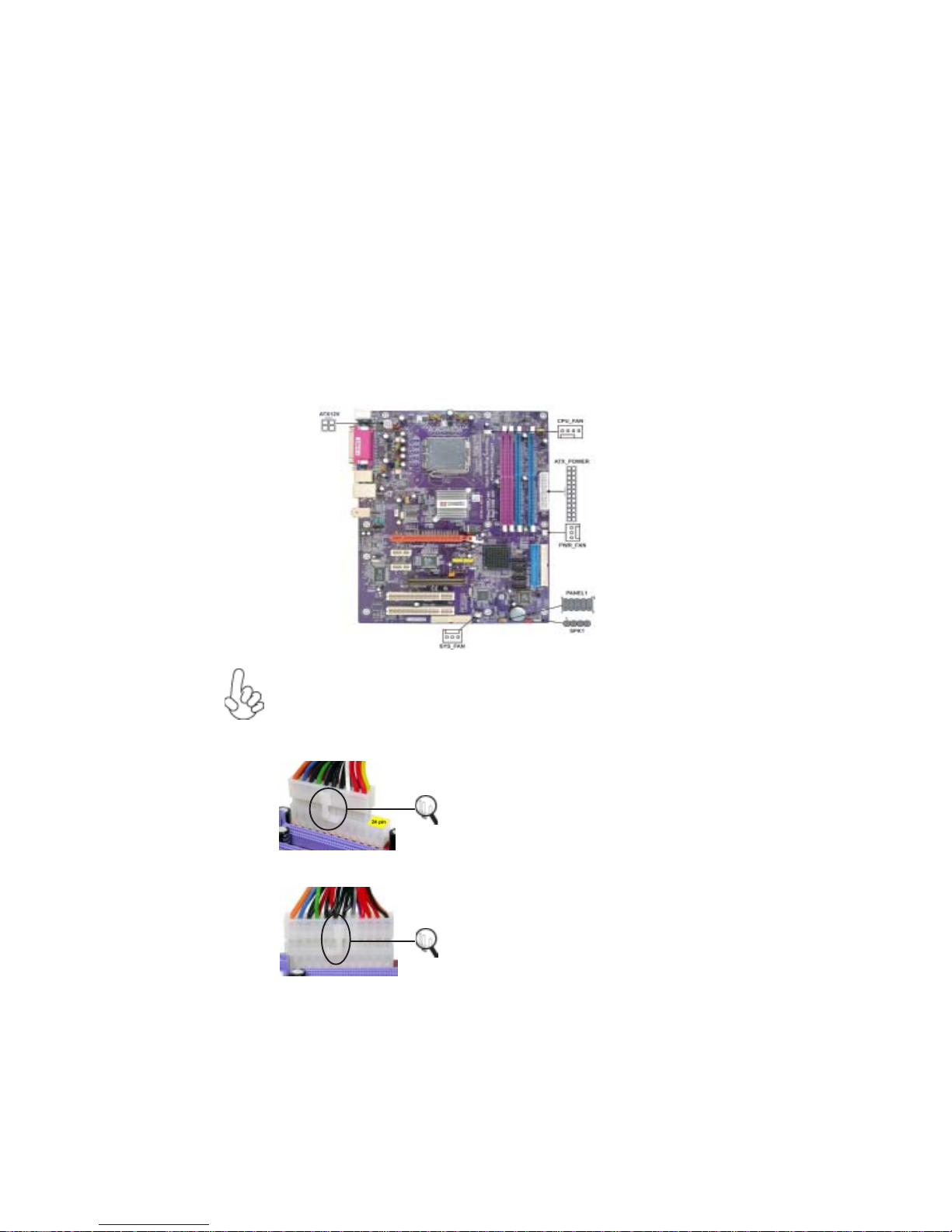
Connecting Case Components
After you have installed the motherboard into a case, you can begin connecting the motherboard components. Refer to the following:
1 Connect the CPU cooling fan cable to CPU_FAN.
2 Connect the system cooling fan connector to SYS_FAN.
3 Connect the power fan connector to PWR_FAN.
4 Connect the case speaker cable to SPK1.
5 Connect the case switches and indicator LEDs to the PANEL1.
6 Connect the standard power supply connector to ATX_POWER.
7 Connect the auxiliary case power supply connector to ATX12V.
Connecting 20/24-pin power cable
Users please note that the 20-pin and 24-pin power cables can both be connected to the ATX1 connector. With the 20-pin power cable, just align the 20pin power cable with the pin 1 of the ATX1 connector. However, using 20-pin
power cable may cause the system to become unbootable or unstable because of
insufficient electricity.
Users please note that when installing 20pin power cable, the latche of power cable
clings to the left side of the ATX_POWER
20-pin power cable
24-pin power cable
connector latch, just as the picture shows.
Users please note that when installing 24pin power cable, the latches of power cable
clings to the right side of the ATX_POWER
connector latch.
Installing the Motherboard
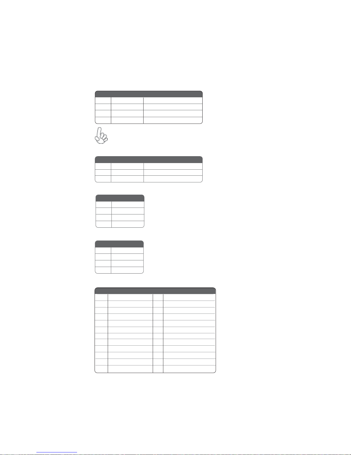
CPU_FAN: F AN Power Connectors
Pin Signal Name Function
1 GND System Ground
+12V Power +12V
2
3 Sense Sensor
4 PWM CPU FAN control
Users please note that the fan connector supports the CPU cooling
fan of 1.1A~2.2A (26.4W max) at +12V.
SYS_FAN/PWR_F AN: F AN Power Connectors
Pin Signal Name Function
1 GND System Ground
+12V Power +12V
2
3 Sense Sensor
SPK1: Internal speaker
Pin Signal Name
1 VCC
2 NC
3 NC
4 Signal
11
A TX12V: A TX 12V Power Connector
Pin Signal Name
1 Ground
2 Ground
3 +12V
4 +12V
A TX_PWR: A TX 24-pin Power Connector
Pin Signal Name Pin Signal Name
1 +3.3V 13 +3.3V
2 +3.3V 14 -12V
3 Ground 15 GND
4 +5V 16 PS_ON
5 Ground 17 GND
6 +5V 18 GND
7 Ground 19 GND
8 PWRGD 20 -5V
9 +5VSB 21 +5V
10 +12V 22 +5V
11 +12V 23 +5V
12 +3.3V 24 GND
Installing the Motherboard
12
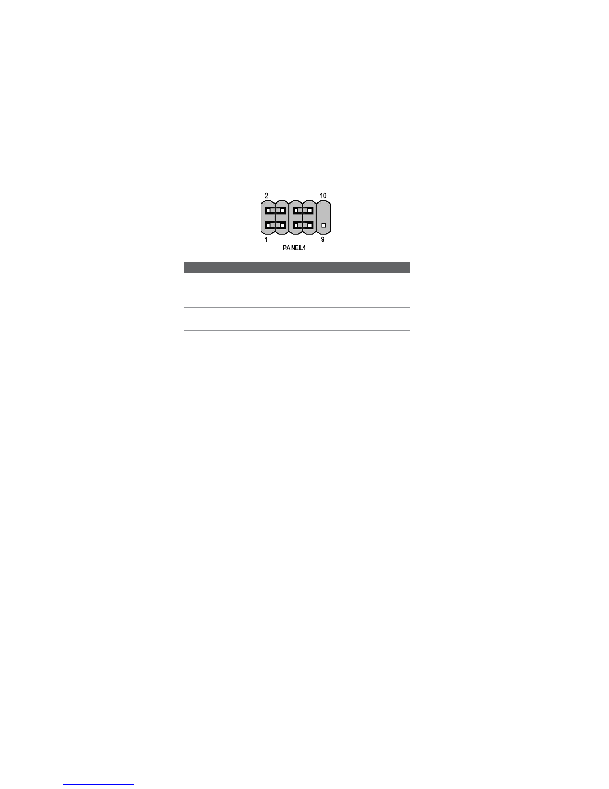
Front Panel Connector
The front panel connector (PANEL1) provides a standard set of switch and LED connectors commonly found on ATX or micro-ATX cases. Refer to the table below for information:
Pin Signal Function Pin Signal Function
1 HD_LED_P Hard disk LED(+) 2 FP PWR/SLP *MSG LED(+)
3 HD_LED_N Hard disk LED(-)
5 RST_SW_N Reset Switch(-)
7 RST_SW_P Reset Switch(+)
9 RSVD Reserved
* MSG LED (dual color or single color)
Hard Drive Activity LED
Connecting pins 1 and 3 to a front panel mounted LED provides visual indication that data
is being read from or written to the hard drive. For the LED to function properly, an IDE
drive should be connected to the onboard IDE interface. The LED will also show activity
for devices connected to the SCSI (hard drive activity LED) connector.
4 FP PWR/SLP *MSG LED(-)
6 PWR_SW_P Power Switch(+)
8 PWR_SW_N Power Switch(-)
10 Key No pin
Power/Sleep/Message waiting LED
Connecting pins 2 and 4 to a single or dual-color, front panel mounted LED provides power
on/off, sleep, and message waiting indication.
Reset Switch
Supporting the reset function requires connecting pin 5 and 7 to a momentary-contact
switch that is normally open. When the switch is closed, the board resets and runs POST.
Power Switch
Supporting the power on/off function requires connecting pins 6 and 8 to a momentarycontact switch that is normally open. The switch should maintain contact for at least 50 ms
to signal the power supply to switch on or off. The time requirement is due to internal debounce circuitry. After receiving a power on/off signal, at least two seconds elapses before
the power supply recognizes another on/off signal.
Installing the Motherboard

Installing Hardware
Installing the Processor
Caution: When installing a CPU heatsink and cooling fan make sure that
you DO NOT scratch the motherboard or any of the surface-mount
resistors with the clip of the cooling fan. If the clip of the cooling fan
scrapes across the motherboard, you may cause serious damage to the
motherboard or its components.
On most motherboards, there are small surface-mount resistors near the
processor socket, which may be damaged if the cooling fan is carelessly
installed.
Avoid using cooling fans with sharp edges on the fan casing and the clips.
Also, install the cooling fan in a well-lit work area so that you can clearly
see the motherboard and processor socket.
Before installing the Processor
This motherboard automatically determines the CPU clock frequency and system bus
frequency for the processor. You may be able to change these settings by making changes
to jumpers on the motherboard, or changing the settings in the system Setup Utility. We
strongly recommend that you do not over-clock processors or other components to run
faster than their rated speed.
Warning: Over-clocking components can adversely affect the reliability
of the system and introduce errors into your system. Over-clocking can
permanently damage the motherboard by generating excess heat in
components that are run beyond the rated limits.
13
This motherboard has a LGA 775 socket. When choosing a processor, consider the performance requirements of the system. Performance is based on the processor design, the clock
speed and system bus frequency of the processor, and the quantity of internal cache memory
and external cache memory.
Installing the Motherboard
14
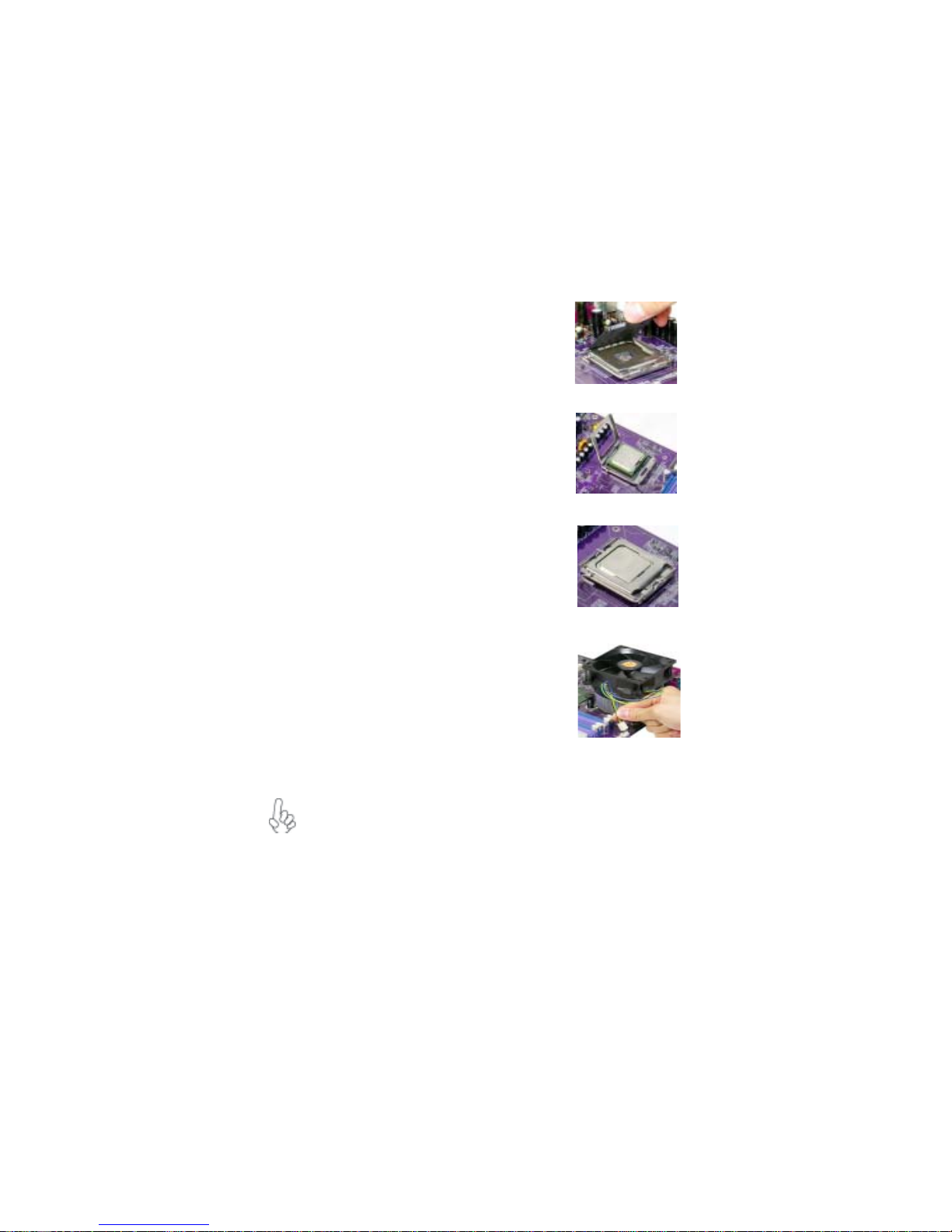
CPU Installation Procedure
The following illustration shows CPU installation components.
A. Unload the cap
· Use thumb & forefinger to hold the
lifting tab of the cap.
· Lift the cap up and remove the cap
completely from the socket.
B. Open the load plate
· Use thumb & forefinger to hold the
hook of the lever, pushing down and pulling
aside unlock it.
· Lift up the lever.
· Use thumb to open the load plate. Be
careful not to touch the contacts.
C. Install the CPU on the socket
· Orientate CPU package to the socket.
Make sure you match triangle marker
to pin 1 location.
D. Close the load plate
· Slightly push down the load plate onto the
tongue side, and hook the lever.
· CPU is locked completely.
E. Apply thermal grease on top of the CPU.
F. Fasten the cooling fan supporting base onto
the CPU socket on the motherboard.
G. Make sure the CPU fan is plugged to the
CPU fan connector. Please refer to the CPU
cooling fan user’s manual for more detail
installation procedure.
To achieve better airflow rates and heat dissipation, we suggest that you use
a high quality fan with 3800 rpm at least. CPU fan and heatsink installation procedures may vary with the type of CPU fan/heatsink supplied. The
form and size of fan/heatsink may also vary.
Installing the Motherboard
Installing Memory Modules
This motherboard accomodates four memory modules. It can support two 184-pin 2.5V
unbuffered DIMM, DDR 400/333/266 or two 240-pin 1.8V DDR2 667/533/400. The
maximum memory capacity is 2GB.
Users please note that DDR & DDR2 can’t both be applied at the same time on
this motherboard. Users can use either DDR or DDR2 memory modules only!
DDR SDRAM memory module table
Memory module Memory Bus
DDR 266 133MHz
DDR 333 166MHz
DDR 400 200MHz
DDR2 SDRAM memory module table
Memory module Memory Bus
DDR2 400 200MHz
DDR2 533 266MHz
DDR2 667 333MHz
You must install at least one module in any of the four slots. Each module can be installed
with 256MB to 1GB of memory.
Do not remove any memory module from its antistatic packaging until you
are ready to install it on the motherboard. Handle the modules only by
their edges. Do not touch the components or metal parts. Always wear a
grounding strap when you handle the modules.
15
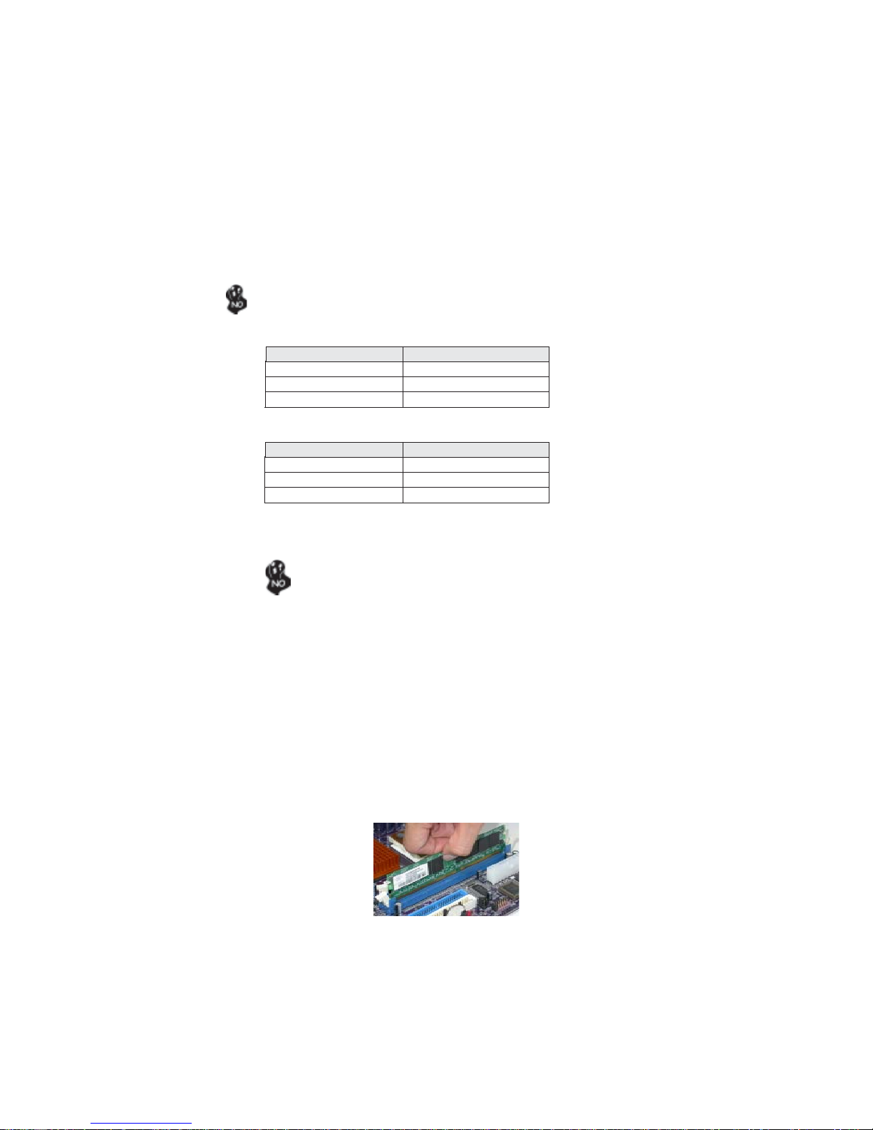
Installation Procedure
Refer to the following to install the memory modules.
1 This motherboard supports unbuffered DDR and DDR2 SDRAM .
2 Push the latches on each side of the DIMM slot down.
3 Align the memory module with the slot. The DIMM slots are keyed with notches
and the DIMMs are keyed with cutouts so that they can only be installed
correctly.
4 Check that the cutouts on the DIMM module edge connector match the notches
in the DIMM slot.
5 Install the DIMM module into the slot and press it firmly down until it seats
correctly. The slot latches are levered upwards and latch on to the edges of
the DIMM.
6 Install any remaining DIMM modules.
Installing the Motherboard
16
Table A: DDR QVL (Qualified Vender List)
The following DDR400 memory modules have been tested and qualified
for use with this motherboard.
Size Vendor Model Name
128MB
256MB
SAMSUNG K4H560838D-TCC4
512MB
SAMSUNG K4H560838E-TCCC
SAMSUNG K4H560838D-TCC4
Infineon HYB25D256160BT-5B
NANYA NT5DS16M16BT-5
NANYA NT5DS16M16BT-5T
Infineon HYB25D256800BT-5B
Micron MT46V16M8-5 ESB
Micron MT46V32M8-5BC
NANYA NT5DS32M8BT-5T
Ramaxel HYB25D256800CE-5C
Apacer A2S56D30ATP
Apacer V58C2256804SAT5
Apacer HYB25D256800BT-5B
Infineon HYB25D256800CE-5C
NANYA NT5DS32M8BT-5T
Table B: DDR2 QVL (Qualified Vender List)
The following DDR2 memory modules have been tested and qualified
for use with this motherboard.
Type Size Vendor Model N ame
DDR2 400 512MB NANYA NT5TU64M8AF-5A
DDR2 533
512MB
DDR2 667 512MB E LPIDA E2508AA-DF-E
elixir N2TU51216AF-37B 256MB
Kingston HYB18T512160AC-3.7
elixir N2TU51280AF-37B
Kingston E5108AB-5C-E ES
NANYA NT5TU64M8AF-37B
SAMSUNG K4T51083QB-GCD5
Installing the Motherboard
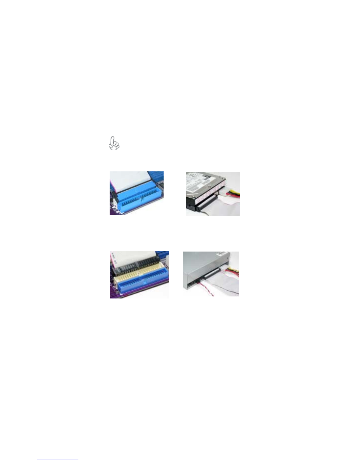
Installing a Hard Dish Drive/CD-ROM/SA T A Hard Drive
This section describes how to install IDE devices such as a hard disk drive and a CD-ROM
drive.
About IDE Devices
Your motherboard has two IDE channel interfaces (IDE1 & IDE2). Two IDE ribbon cables
supporting four IDE devices is bundled with the motherboard.
You must orient the cable connector so that the pin1 (color) edge of the
cable correspoinds to the pin 1 of the I/O port connector.
IDE1: Primary IDE Connector
The first hard drive should always be connected to IDE1.
IDE2: Secondary IDE Connector
The second drive on this controller must be set to slave mode. The cinfiguration is the same
as IDE1.
17
IDE devices enclose jumpers or switches used to set the IDE device as MASTER or SLAVE.
Refer to the IDE device user’s manual. Installing two IDE devices on one cable, ensure that
one device is set to MASTER and the other device is set to SLAVE. The documentation of
your IDE device explains how to do this.
Installing the Motherboard
18
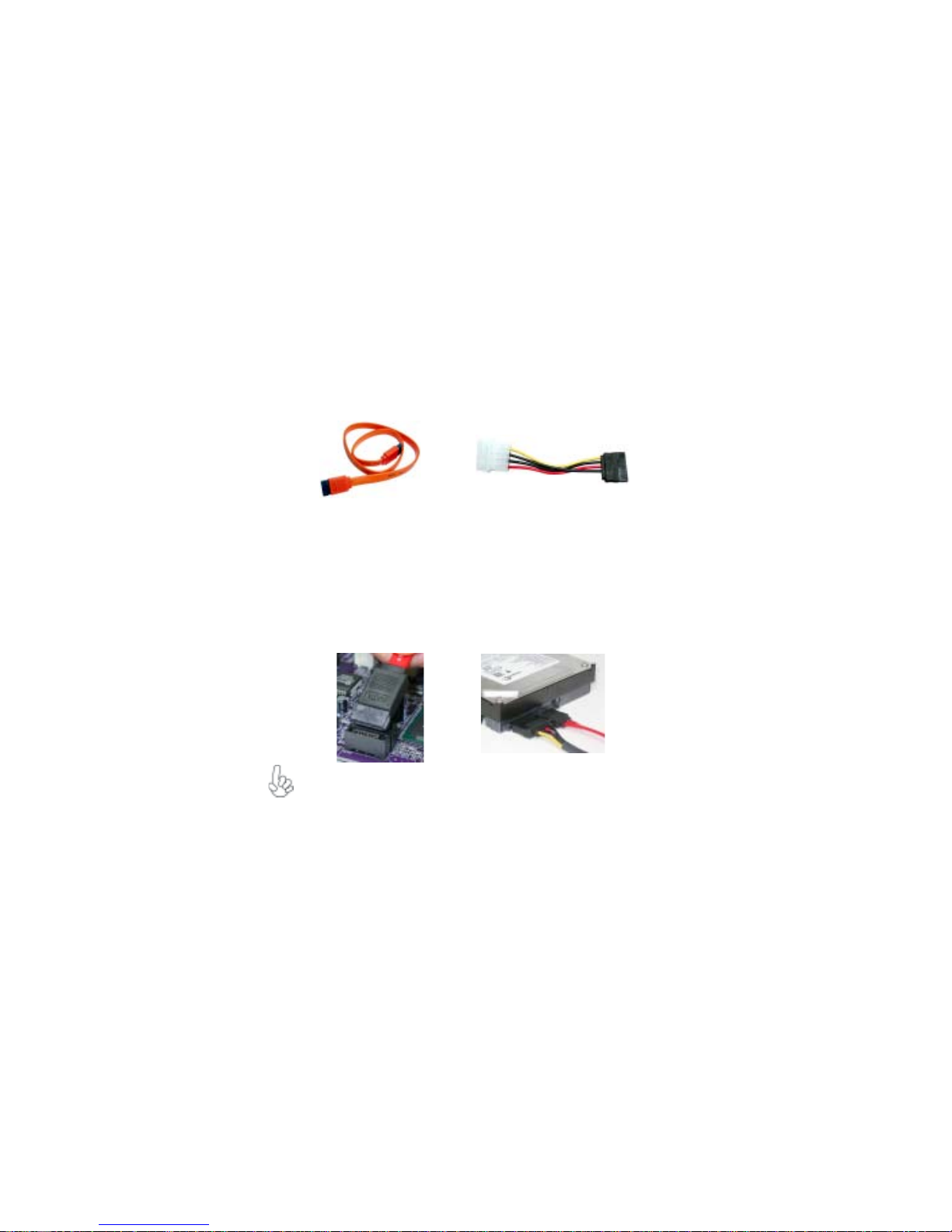
About SAT A Connectors
This motherboard features four SATA connectors supporting a total of four drives. SATA ,
or Serial ATA (Advanced Technology Attachment) is the standard interface for the IDE
hard drives which are currently used in most PCs. These connectors are well designed and
will only fit in one orientation. Locate the SATA connectors on the motherboard and follow
the illustration below to install the SATA hard drives.
Installing Serial A T A Hard Drives
To install the Serial ATA (SATA) hard drives, use the SATA cable that supports the Serial
ATA protocol. This SATA cable comes with an SATA power cable. You can connect either
end of the SATA cable to the SATA hard drive or the connector on the motherboard.
SATA cable
Refer to the illustration below for proper installation:
1 Attach either cable end to the connector on the motherboard.
2 Attach the other cable end to the SATA hard drive.
3 Attach the SATA power cable to the SATA hard drive and connect the other
end to the power supply.
This motherboard does not support the “Hot-Plug” function.
(optional)
SATA power cable (optional)
Installing the Motherboard
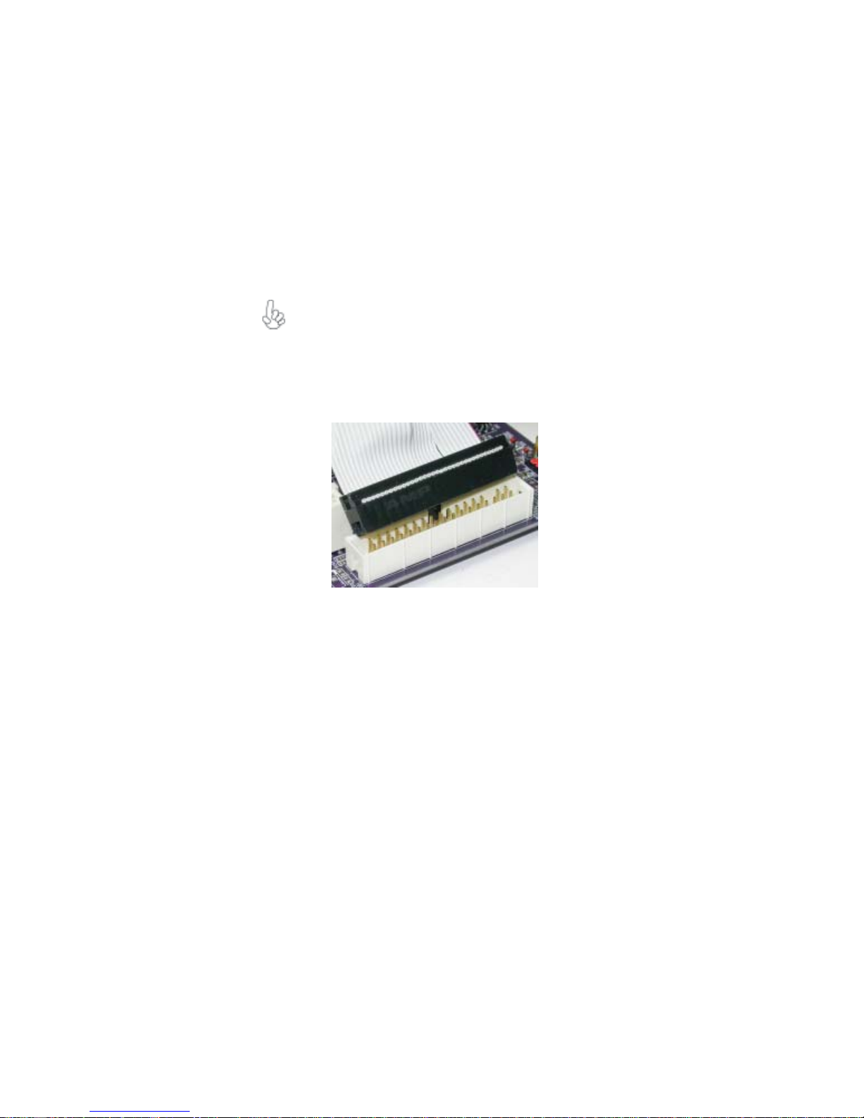
Installing a Floppy Diskette Drive
The motherboard has a floppy diskette drive (FDD) interface and ships with a diskette drive
ribbon cable that supports one or two floppy diskette drives. You can install a 5.25-inch
drive and a 3.5-inch drive with various capacities. The floppy diskette drive cable has one
type of connector for a 5.25-inch drive and another type of connector for a 3.5-inch drive.
You must orient the cable connector so that the pin 1 (color) edge of the
cable corresponds to the pin 1 of the I/O port connector.
FDD: Floppy Disk Connector
This connector supports the provided floppy drive ribbon cable. After connecting the single
end to the onboard floppy connector, connect the remaining plugs on the other end to the
floppy drives correspondingly.
19
Installing the Motherboard
20
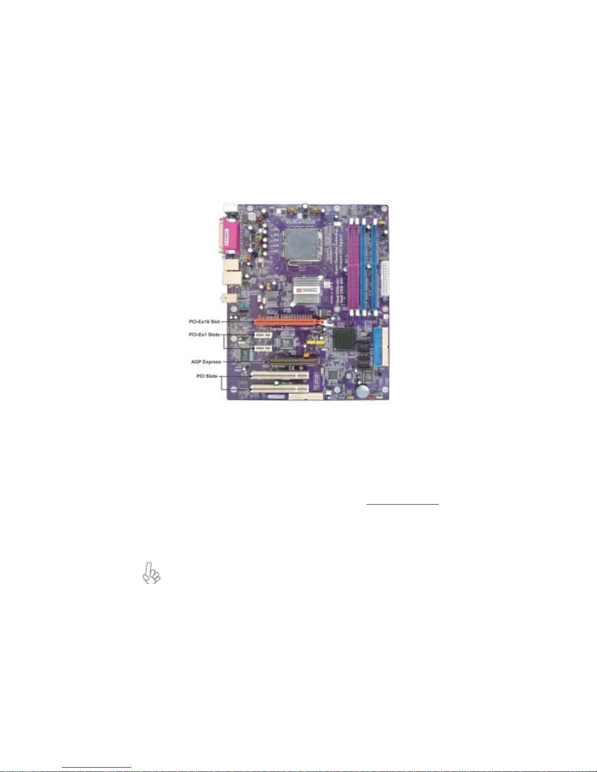
Installing Add-on Cards
The slots on this motherboard are designed to hold expansion cards and connect them to the
system bus. Expansion slots are a means of adding or enhancing the motherboard’s features
and capabilities. With these efficient facilities, you can increase the motherboard’s capabilities by adding hardware that performs tasks that are not part of the basic system.
PCIEX16
Slot
PCIE1~2
Slots
AGP
Express
Slot
PCI 1/2
Slots
The PCI Express x16 slot is used to install an external PCI Express graphics
card that is fully compliant to the PCI Express Base Specification revision
1.0a.
These two PCI Express x1 slots are fully compliant to the PCI Express Base
Specification revision 1.0a as well.
The AGP Express slot is used to install an AGP graphics card that emulates
the AGP function. To get better performance and compatibility on our
special designed AGP Express slot, we recommend users use one of the AGP
graphics cards that have been tested by out company. See the “Supported
AGP 8X/4X VGA Cards List” or visit our website at “
for the updated supported list.
This motherboard is equipped with two standard PCI slots. PCI stands for
Peripheral Component Interconnect and is a bus standard for expansion
cards, which for the most part, is a supplement of the older ISA bus standard.
The PCI slots on this board are PCI v2.3 compliant.
1.Before installing an add-on card, check the documentation for the card carefully.
If the card is not Plug and Play, you may have to manually configure the card
before installation.
2.Some PCI-E x16 graphics cards may be so bulky that it could block one PCI-E
x1 slot.
3.Please pull out the PCI-Ex16 graphics card straightway to remove it when you
want to uninstall it.
http://www.ecs.com.tw”
Installing the Motherboard

Table C : Supported AGP 8X/4X VGA Cards List
VGA Chip Mod e l n ame 4X/8X
ASUS Geforce 4 MX440 64MB
ELSA 511 .Geforce 2 MX400 64MB
ASUS V9560/7D 128MB
BiTC GeForce FX5200 128M DDR
BiTC GeForce FX5600 128 MB DDR
BiTC GeForce4 MX440 64M DDR
BiTC 3306 GF4@MX400 64MB
ELSA FX935/128MB/VIVO/DVI
Gainward GeforceFX 5200DT 64MB
nVIDIA
ATI
SIS
Gigabyte GeForce FX5700U 128MDDR
Leadtek WinFast A280 LE TD GF4 Ti4200
128MB DDR SDRAM
Leadtek WinFast A380 GeForce FX5950 Ultra
TDM 256MB DDR
MAXSUN MS-5600XT-W-64B-DT
Millennium Silver TI4600 128 MB
MSI FX5600XT-128MB
MSI GeForce FX5800-TD 128MB DDR
MSI Feforce4 Titanium4200
Winfast A360TD FX5700 128MB
Winfast Geforce FX5900 A350TDH
UNIKA GeForce4 Ti4200 64MB
ATI R7500 64MB DDR
ATI R9000 128MB DDR
ATI Radeon 9250 64MB DDR
ATI Radeon 9500 64MB DDR
ATI Radeon 9700pro 128MB DDR
ATI Radeon 9000 PRO 128MB DDR
Colorful Radeon 9200 CF 64MB
ECS R9200LE-64T
Manli Radeon 9800XT 128MB
ECS AG400_D64 V1.0 Xabre400 64MB DDR
SDRAM (8X)
21
4X
8X
4X
8X
8X
For the latest updates of the supported AGP VGA cards list, please visit
ECS ELITEGROUP website for details.
ECS ELITEGROUP website:
http://www.ecs.com.tw
Installing the Motherboard

22
Follow these instructions to install an add-on card:
1 Remove a blanking plate from the system case corresponding to the slot you
are going to use.
2 Install the edge connector of the add-on card into the expansion slot. Ensure
that the edge connector is correctly seated in the slot.
3 Secure the metal bracket of the card to the system case with a screw.
For some add-on cards, for example graphics adapters and network adapters, you have to install drivers and software before you can begin using the
add-on card.
Installing the Motherboard

Connecting Optional Devices
Refer to the following for information on connecting the motherboard’s optional devices:
23
AUDIO1: Front Panel Audio header
This header allows the user to install auxiliary front-oriented microphone and line-out ports
for easier access.
Pin Signal Name Function
1 AUD_MIC Front Panel Microphone input signal
2 AUD_GND Ground used by Analog Audio Circuits
3 AUD_MIC_BIAS Microphone Power
4 AUD_VCC Filtered +5V used by Analog Audio Circuits
5 AUD_F_R Right Channel audio signal to Front Panel
6 AUD_RET_R Right Channel Audio signal to Return from Front Panel
7 REVD Reserved
8 Key No Pin
9 AUD_F_L Left Channel Audio signal to Front Panel
10 AUD_RET_L Left Channel Audio signal to Return from Front Panel
Pin Signal Name
CD_IN: Analog audio input header
Pin Signal Name Function
1 CD in_L CD In left channel
GND Ground
2
GND Ground
3
CD in_R CD In right channel
4
Installing the Motherboard

24
SAT A1/2/3/4: Serial A T A connectors
These connectors are use to support the new Serial ATA devices for the highest date transfer
rates (150 MB/s), simpler disk drive cabling and easier PC assembly. It eliminates limitations
of the current Parallel ATA interface. But maintains register compatibility and software
compatibility with Parallel ATA.
Pin Signal Name
Pin Signal Name Function
1 Ground 2 TX+
Pin Signal Name
3 TX- 4 Ground
5 RX- 6 RX+
7 Ground - -
SPDIFO1: SPDIF out header
This is an optional header that provides an S/PDIF (Sony/Philips Digital Interface) output
to digital multimedia device through optical fiber or coxial connector.
Pin Signal Name
Pin Signal Name Function
1 SPDIF SPDIF digital output
Function
2 +5VA 5V analog power
3 Key No pin
4 GND Ground
USB3/4: Front Panel USB header
The motherboard has four USB ports installed on the rear edge I/O port array. Additionally,
there are two USB headers onboard. Use the auxiliary USB headers to connect the frontmounted ports to the motherboard.
Pin Signal Name Function
1 USBPWR Front Panel USB Power
2 USBPWR Front Panel USB Power
3 USB_FP_P0- USB Port 0 Negative Signal
4 USB_FP_P1- USB Port 1 Negative Signal
5 USB_FP_P0+ USB Port 0 Positive Signal
6 USB_FP_P1+ USB Port 1 Positive Signal
7 GND Ground
8 GND Ground
9 Key No pin
10 USB_FP_OC0 Overcurrent signal
AUX_IN: Auxliary In header (optional)
Pin Signal Name Function
1 AUX_L AUX In left channel
GND Ground
2
3
GND Ground
4
AUX_R AUX In right channel
Installing the Motherboard

IR1: Infrared port
The mainboard supports an Infrared (IR1) data port. Infrared ports allow the wireless
exchange of information between your computer and similarly equipped devices such as
printers, laptops, Personal Digital Assistants (PDAs), and other computers.
Pin Signal Name Function
1 NC Not connected
2 Key No p in
3 +5V IR Power
4 GND Ground
5 IRTX IrDA serial output
6 IRRX IrDA serial input
TV_OUT : TV -out header (optional)
Users may connect this header to your TV set to achieve the TV-out function.
Pin Signal Name Function
1 GND Ground
2 COMP Composite
3 Y Luminance
4 GND Ground
5C Chrominance
6 KEY No pin
25
Installing the Motherboard

26
Connecting I/O Devices
The backplane of the motherboard has the following I/O ports:
PS2 Mouse Use the upper PS/2 port to connect a PS/2 pointing device.
PS2 Keyboard Use the lower PS/2 port to connect a PS/2 keyboard.
Parallel Port Use LPT1 to connect printers or other parallel communications
(LPT1) devices.
Serial Port Use the COM port to connect serial devices such as mice or
(COM1) fax/modems. COM1 is identified by the system as COM1/3.
VGA Port Connect your monitor to the VGA port.
LAN Port Connect an RJ-45 jack to the LAN port to connect your computer
(optional) to the Network.
USB Ports Use the USB ports to connect USB devices.
Audio Ports Use the three audio ports to connect audio devices. The first jack
This concludes Chapter 2. The next chapter covers the BIOS.
is for stereo line-in signal. The second jack is for stereo line-out
signal. The third jack is for microphone.
Installing the Motherboard

Chapter 3
Using BIOS
About the Setup Utility
The computer uses the latest Award BIOS with support for Windows Plug and Play. The
CMOS chip on the motherboard contains the ROM setup instructions for configuring the
motherboard BIOS.
The BIOS (Basic Input and Output System) Setup Utility displays the system’s configuration status and provides you with options to set system parameters. The parameters are
stored in battery-backed-up CMOS RAM that saves this information when the power is
turned off. When the system is turned back on, the system is configured with the values you
stored in CMOS.
The BIOS Setup Utility enables you to configure:
• Hard drives, diskette drives and peripherals
• Video display type and display options
• Password protection from unauthorized use
• Power Management features
The settings made in the Setup Utility affect how the computer performs. Before using the
Setup Utility, ensure that you understand the Setup Utility options.
27
This chapter provides explanations for Setup Utility options.
The Standard Configuration
A standard configuration has already been set in the Setup Utility. However, we recommend
that you read this chapter in case you need to make any changes in the future.
This Setup Utility should be used:
• when changing the system configuration
• when a configuration error is detected and you are prompted to make changes
to the Setup Utility
• when trying to resolve IRQ conflicts
• when making changes to the Power Management configuration
• when changing the password or making other changes to the Security Setup
Entering the Setup Utility
When you power on the system, BIOS enters the Power-On Self Test (POST) routines.
POST is a series of built-in diagnostics performed by the BIOS. After the POST routines are
completed, the following message appears:
Using BIOS

28
Press DEL to enter SETUP
Pressing the delete key accesses the BIOS Setup Utility:
Phoenix-AwardBIOS CMOS Setup Utility:
Standard CMOS Features
f
Advanced BIOS Features Load Fail-Safe Defaults
f
Advanced Chipset Features Load Optimized Defaults
f
Integrated Peripherals Set Supervisor Password
f
Power Management Setup Set User Password
f
PnP/PCI Configurations Save & Exit Setup
f
PC Health Status Exit Without Saving
f
Esc: Quit
F10: Save & Exit Setup
Time, Date, Hard Disk Type...
BIOS Navigation Keys
The BIOS navigation keys are listed below:
KEY FUNCTION
ESC Exits the current menu
oqrtoqrt
oqrt
oqrtoqrt
+/-/PU/PD Modifies the selected field’s values
F10 Saves the current configuration and exits setup
F1 Displays a screen that describes all key functions
F5 Loads previously saved values to CMOS
F6 Loads a minimum configuration for troubleshooting
F7 Loads an optimum set of values for peak performance
Scrolls through the items on a menu
Frequency/Voltage Control
f
mnlk
: Select Item
Using BIOS

Updating the BIOS
You can download and install updated BIOS for this motherboard from the manufacturer’s
Web site. New BIOS provides support for new peripherals, improvements in performance,
or fixes for known bugs. Install new BIOS as follows:
1 If your motherboard has a BIOS protection jumper, change the setting to allow
BIOS flashing.
2 If your motherboard has an item called Firmware Write Protect in Advanced
BIOS features, disable it. (Firmware Write Protect prevents BIOS from being
overwritten.
3 Create a bootable system disk. (Refer to Windows online help for information
on creating a bootable system disk.)
4 Download the Flash Utility and new BIOS file from the manufacturer’s Web
site. Copy these files to the system diskette you created in Step 3.
5 Turn off your computer and insert the system diskette in your computer’s
diskette drive. (You might need to run the Setup Utility and change the boot
priority items on the Advanced BIOS Features Setup page, to force your
computer to boot from the floppy diskette drive first.)
6 At the A:\ prompt, type the Flash Utility program name and press <Enter>.
7 Type the filename of the new BIOS in the “File Name to Program” text box.
Follow the onscreen directions to update the motherboard BIOS.
8 When the installation is complete, remove the floppy diskette from the diskette
drive and restart your computer. If your motherboard has a Flash BIOS jumper ,
reset the jumper to protect the newly installed BIOS from being overwritten.
29
Using BIOS
When you start the Setup Utility, the main menu appears. The main menu of the Setup
Utility displays a list of the options that are available. A highlight indicates which option is
currently selected. Use the cursor arrow keys to move the highlight to other options. When
an option is highlighted, execute the option by pressing <Enter>.
Some options lead to pop-up dialog boxes that prompt you to verify that you wish to
execute that option. Other options lead to dialog boxes that prompt you for information.
Some options (marked with a triangle
values for the option. Use the cursor arrow keys to scroll through the items in the submenu.
In this manual, default values are enclosed in parenthesis. Submenu items are denoted by a
ff
triangle
f .
ff
ff
f) lead to submenus that enable you to change the
ff
Using BIOS

30
Standard CMOS Features
This option displays basic information about your system.
Phoenix-AwardBIOS CMOS Setup Utility
Standard CMOS Features
Date (mm:dd:yy) Mon, Nov 17 2004
Time (hh:mm:ss) 13 : 4 : 54
IDE Channel 0 Master [ST380011A]
f
IDE Channel 0 Slave [None]
f
IDE Channel 1 Master [None]
f
IDE Channel 1 Slave [ATAPI 52X CDROM]
f
IDE Channel 2 Master
IDE Channel 3 Master
IDE Channel 4 Master
IDE Channel 5 Master
Drive A [1.44M, 3.5 in.]
Video [EGA/VGA]
Halt On [All Errors]
Base Memory 640K
Extended Memory 65535K
T otal Memory 1024K
: Move Enter: Select +/-/PU/PD:Value F10:Save ESC:Exit F1: General Help
mnlk
F5:Previous Values F6:Fail-Safe Defaults F7:Optimized Defaults
Date and Time
The Date and Time items show the current date and time on the computer. If
you are running a Windows OS, these items are automatically updated whenever you make
changes to the Windows Date and Time Properties utility.
fIDE Devices
Your computer has two IDE channels (Primary and Secondary) and each channel can be
installed with one or two devices (Master and Slave). In addition, this motherboard supports
four SATA channels (Primary and Secondary) and each channel allows one SATA device to
be installed. Use these items to configure each device on the IDE channel.
Press <Enter> to display the IDE submenu
Phoenix-AwardBIOS CMOS Setup Utility
IDE HDD Auto-Detection [ Press Enter]
IDE Channel 0 Master [Auto]
Access Mode [Auto]
Capacity 80 GB
Cylinder 38309
Head 16
Precomp 0
Landing Zone 38308
Sector 255
:
IDE Channel 0 Master
Item Help
Menu Level
Change the day, month,
year and century.
Item Help
Menu Level
To auto-detect the HDD’ s
size, head...on this channel
f
f
f
: Move Enter: Select +/-/PU/PD:Value F10:Save ESC:Exit F1: General Help
mnlk
F5:Previous Values F6:Fail-Safe Defaults F7:Optimized Defaults
IDE HDD Auto-Detection
Press <Enter> while this item is highlighted to prompt the Setup Utility to automatically
detect and configure an IDE device on the IDE channel.
Using BIOS

If you are setting up a new hard disk drive that supports LBA mode, more
than one line will appear in the parameter box. Choose the line that lists
LBA for an LBA drive.
IDE Channel 0/1 Master/Slave/Extended IDE Drives (Auto)
Leave this item at Auto to enable the system to automatically detect and configure
IDE devices on the channel. If it fails to find a device, change the value to Manual and
then manually configure the drive by entering the characteristics of the drive in the
items described below. Please noted that if you choose IDE Channel 2/3/4/5 Master, the
item may change to Extended IDE Drive.
Refer to your drive’s documentation or look on the drive casing if you need to obtain
this information. If no device is installed, change the value to None.
Before attempting to configure a hard disk drive, ensure that you have the
configuration information supplied by the manufacturer of your hard drive.
Incorrect settings can result in your system not recognizing the installed
hard disk.
Access Mode (Auto)
This item defines ways that can be used to access IDE hard disks such as LBA (Large
Block Addressing). Leave this value at Auto and the system will automatically decide
the fastest way to access the hard disk drive.
Press <Esc> to return to the Standard CMOS Features page.
Drive A (1.44M, 3.5 in./None)
These items define the characteristics of any diskette drive attached to the system.
You can connect one or two diskette drives.
Video (EGA/VGA)
This item defines the video mode of the system. This motherboard has a built-in VGA
graphics system; you must leave this item at the default value.
31
Halt On (All Errors)
This item defines the operation of the system POST (Power On Self Test) routine. You
can use this item to select which types of errors in the POST are sufficient to halt the
system.
Base Memory, Extended Memory, and Total Memory
These items are automatically detected by the system at start up time. These are
display-only fields. You cannot make changes to these fields.
Using BIOS

32
3
3
Advanced BIOS Features
This option defines advanced information about your system.
AT A 66/100 IDE Cable Msg. [Enabled]
CPU Feature [Press Enter]
f
Hard Disk Boot Priority [Press Enter]
f
CPU L1 & L2 Cache [Enabled]
Hyper-Threading Technology [Enabled]
Quick Power On Self Test [Enabled]
First Boot Device [Floppy]
Second Boot Device [Hard Disk]
Third Boo t De vic e [CDROM]
Boot Other Device [Enabled]
Boot Up Floppy Seek [Disabled]
Boot Up NumLock Status [On]
Gate A20 Option [Fast]
Typematic Rate Setting [Disabled]
Typematic Rate (Chars/Sec ) 6
X
Typematic Delay (Msec) 25 0
X
Security Option [Setup]
APIC Mode [Enabled]
OS Select For DRAM > 64MB [Non-OS2]
HDD S.M.A.R.T. Capability [Disabled]
: Move Enter: Select +/-/PU/PD:Value F10:Save ESC:Exit F1: General Help
mnlk
F5:Previous Values F6:Fail-Safe Defaults F7:Optimized Defaults
CPU Feature (Press Enter)
f
Users please note that this function is only available for Prescott CPUs. Scroll to this
item and press <Enter> to view the following screen:
Phoenix-AwardBIOS CMOS Setup Utility
Advanced BIOS Features
Phoenix-AwardBIOS CMOS Setup Utility
CPU Feature
Item Help
f
Menu Level
2
2
f
f
Thermal Management [Thermal Monitor 1]
TM2 Bus Ratio [14 X]
TM2 Bus VID [1.2000V]
Limit CPUID MaxVal [Disabled]
Execute Disable Bit [Enabled]
: Move Enter: Select +/-/PU/PD:Value F10:Save ESC:Exit F1: General Help
mnlk
F5:Previous Values F6”Fail-Safe Defaults F7:Optimized
Item Help
Menu Level
Thermal Monitor 1 (On die
throtting)
Thermal Monitor 2 Ratio
& VID transition
Thermal Management (Thermal Monitor 1)
This item displays CPU’s temperature and enables you to set a safe
temperature to Prescott CPU.
TM2 Bus Ratio (14X)
This item helps you to set the frequency (bus ratio) of the throttled
performance that will be initiated when the on-die sensor goes from not
hot to hot. You may set the bus ratio number from 0-255. This feature is
available when CPU supports Thermal Monitor 2.
Using BIOS
ff

TM2 Bus VID (1.2000V)
This item helps you to set the voltage of the throttled performance that will be
initiated when the on-die sensor goes from not hot to hot. This feature is available
when CPU supports Thermal Monitor 2.
Limit CPUID MaxVal (Disabled)
This item can support Prescott CPUs for old OS. Users please note that under NT 4.0, it
must be set “Enabled”, while under WinXP, it must be set “Disabled”.
Execute Disable Bit (Enabled)
Enable this item to prevent certain classes of malicious “buffer overflow” attacks when
combined with a supporting operating system.
Press <Esc> to return to the Advanced BIOS Features screen.
f
Hard Disk Boot Priority (Press Enter)
Scroll to this item and press <Enter> to view the following screen: Use this table to
decide the disk boot priority.
1. Ch0 M. : ST38001 1A
8. Bootable Add-in Cards
Phoenix-AwardBIOS CMOS Setup Utility
Hard Disk Boot Priority
Menu Level
Item Help
ff
Use < > or < > to select
m
a device, then press <+> to
move it up, or <-> to move it
down the list. Press <ESC>
to exit this menu.
n
33
: Move PU/PD/+/-/: Change Priority F10:Save ESC:Exit
mn
CPU L1 & L2 Cache (Enabled)
All processors that can be installed in this mainboard use internal level 1 (L1) and external
level 2 (L2) cache memory to improve performance. Leave this item at the default value
for better performance.
Hyper-Threading Technology (Enabled)
This item is only available when the chipset supports Hyper-Threading and you are using a
Hyper-Threading CPU.
Quick Power On Self Test (Enabled)
Enable this item to shorten the power on testing (POST) and have your system start
up faster. You might like to enable this item after you are confident that your system
hardware is operating smoothly.
First/Second/Third Boot Device (Floppy/Hard Disk/CDROM)
Use these three items to select the priority and order of the devices that your system
searches for an operating system at start-up time.
Boot Other Device (Enabled)
When enabled, the system searches all other possible locations for an operating system if
it fails to find one in the devices specified under the First, Second, and Third boot devices.
Using BIOS

34
Boot Up Floppy Seek (Disabled)
If this item is enabled, it checks the size of the floppy disk drives at start-up time. You
don’t need to enable this item unless you have a legacy diskette drive with 360K capacity.
Boot Up NumLock Status (On)
This item defines if the keyboard Num Lock key is active when your system is started.
Gate A20 Option (Fast)
This item defines how the system handles legacy software that was written for an earlier
generation of processors. Leave this item at the default value.
Typematic Rate Setting (Disabled)
If this item is enabled, you can use the following two items to set the typematic rate and the
typematic delay settings for your keyboard.
• Typematic Rate (Chars/Sec): Use this item to define how many characters
per second are generated by a held-down key.
• Typematic Delay (Msec): Use this item to define how many milliseconds
must elapse before a held-down key begins generating repeat characters.
Security Option (Setup)
If you have installed password protection, this item defines if the password is required at
system start up, or if it is only required when a user tries to enter the Setup Utility.
APIC Mode (Enabled)
This item allows you to enable or disable the APIC (Advanced Programmable Interrupt
Controller) mode. APIC provides symmetric multi-processing (SMP) for systems, allowing
support for up to 60 processors.
OS Select For DRAM > 64 MB (Non-OS2)
This item is only required if you have installed more than 64 MB of memory and you are
running the OS/2 operating system. Otherwise, leave this item at the default.
HDD S.M.A.R.T Capability (Disabled)
The S.M.A.R.T. (Self-Monitoring, Analysis, and Reporting Technology) system is a
diagnostics technology that monitors and predicts device performance. S.M.A.R.T.
software resides on both the disk drive and the host computer.
Using BIOS

Advanced Chipset Features
These items define critical timing parameters of the motherboard. You should leave the
items on this page at their default values unless you are very familiar with the technical
specifications of your system hardware. If you change the values incorrectly, you may
introduce fatal errors or recurring instability into your system.
Phoenix-AwardBIOS CMOS Setup Utility
Advanced Chipset Features
35
Current MRC Version 3.3
Current RSB Frequency 133 MHz
Current DRAM Frequency 200 MHz
Memory Clock [Auto]
UMA Frame Buffer Size [32MB]
Adjust DRAM Timing [Press Enter]
f
Video Display Devices [Auto]
TV Standard [NTSC]
System BIOS Cacheable [Disabled]
: Move Enter: Select +/-/PU/PD:Value F10:Save ESC:Exit F1: General Help
mnlk
F5:Previous Values F6:Fail-Safe Defaults F7:Optimized Default s
Item Help
Menu Level
f
Current MRC Version, FSB Frequency, DRAM Frequency
This item shows the current ATI Memory Reference code version, current FSB frequency,
and DRAM frequency. Users cannot make changes to it.
Memory Clock (Auto)
This item enable users to manually set the memory clock or leave it at the default auto
setting.
UMA Frame Buffer Size (32MB)
This item enable users to adjust the UMA frame buffer size manually.
Using BIOS

36
Adjust DRAM T iming (Press Enter)
f
Scroll to this item and press <Enter> to view the following screen:
Phoenix-AwardBIOS CMOS Setup Utility
Adjust DRAM Timing
Single Addr Translation [Disable]
LAQ Bypass [Enable]
PIF Stage [Disable]
Channel Map NB [2]
Channel Map GFX [ 4]
Bank0 Map [7]
Bank1 Map [13]
Bank0 Map NB [7]
Bank1 Map NB [13]
Dynamic Clock [Disable]
AUTO Calibration [Enabled]
AUTO DQS [Disable]
Split Channel [Manual]
Addr Step 15T [00]
Addr Step Enable [01]
Impedence Control [Disable]
: Move Enter: Select +/-/PU/PD:Value F10:Save ESC:Exit F1: General Help
mnlk
F5:Previous Values F6:Fail-Safe Defaults F7:Optimized Default s
Item Help
Menu Level
f
Single Addr Translation (Disable)
This item enables or disables the single address translation function of DRAM timing.
LAQ Bypass (Enable)
This item enables or disables the LAQ bypass function of DRAM timing.
PIF Stage (Disable)
This item enables or disables the PIF stage function of DRAM timing.
Channel Map NB (2)
This item allows users to manually adjust the value of Channle Map NB.
Channel Map GFX (4)
This item allows users to manually adjust the value of Channle Map GFX.
Bank0/1 Map/Map NB (7) (13)
This item allows users to manually adjust the value of Bank0 & Bank1 Map & Map NB.
Dynamic Clock (Disable)
This item allows users to enable or disable the dynamic clock function of the DRAM
timing.
AUTO Calibration (Enable)
This item allows users to enable or disable the AUTO calibration function of the DRAM
timing.
AUTO DQS (Disable)
This item allows users to enable or disable the AUTO DQS function of the DRAM timing.
Using BIOS

Split Channel (Manual)
This item allows users to manually or automacially set the split channel of the DRAM
setting.
Addr Step 15T (00)
This item allows users to manually adjust the value of Addr Step 15T of the DRAM
timing.
Addr Step Enable (01)
This item allows users to manually adjust the value of Addr Step Enable of the DRAM
timing.
Impedence Control (Disable)
This item allows users to enable or disable the Impendence Control of the DRAM timing.
Press <Esc> to return to the Advanced Chipset Features screen.
Video Display Devices (Auto)
Users may use this item to set up the video display devices.
TV Standard (NTSC)
Users may use this item to set up TV Standard mode.
System BIOS Cacheable (Disabled)
When this item is enabled, the System BIOS will be cached for faster execution.
Press <Esc> to return to the Main BIOS Setting screen.
37
Using BIOS

38
Integrated Peripherals
These options display items that define the operation of peripheral components on the
system’s input/output ports.
Phoenix-AwardBIOS CMOS Setup Utility
Integrated Peripherals
South OnChip IDE Device [Press Enter]
f
South OnChip PCI Device [Press Enter]
f
SuperIO Device [Press Enter]
f
Init Display First [PCIEx]
x
Surroundview Disabled
Onboard LAN Device [Enabled]
Onboard Lan Boot ROM [Disalbed]
Onboard 1394 Device [Enabled]
: Move Enter: Select +/-/PU/PD:Value F10:Save ESC:Exit F1: General Help
mnlk
F5:Previous Values F6:Fail-Safe Defaults F7:Optimized Defaults
Item Help
Menu Level
f
fSouth OnChip IDE Device (Press Enter)
Scroll to this item and press <Enter> to view the following screen:
Phoenix-AwardBIOS CMOS Setup Utility
OnChip IDE Device
IDE DMA transfer access [Enabled]
OnChip IDE Channel0 [Enabled]
Onchip IDE Channel1 [Enabled]
IDE Prefetch Mode [Disabled]
Primary Master PIO [Auto]
Primary Slave PIO [Auto]
Secondary Master PIO [Auto]
Secondary Slave PIO [Auto]
Primary Master UDMA [Auto]
Primary Slave UDMA [Auto]
Secondary Master UDMA [Auto]
Secondary Slave UDMA [Auto]
IDE HDD Block Mode [Enabled]
: Move Enter: Select +/-/PU/PD:Value F10:Save ESC:Exit F1: General Help
mnlk
F5:Previous Values F6:Fail-Safe Defaults F7:Optimized Defaults
Item Help
Menu Level
IDE DMA transfer access (Enabled)
This item allows you to enable the transfer access of the IDE DMA.
OnChip IDE Channel0/1 (Enabled)
This item allows you to enable or disable the OnChip IDE Channel0/1.
Using BIOS
ff

IDE Prefetching (Enabled)
The onboard IDE drive interface supports IDE prefetching, for faster drives. If you install
a primary and secondary add-in IDE interface, set this field to Disabled if the interface does
not support prefetching.
Primary/Secondary Master/Slave PIO (Auto)
Each IDE channel supports a master device and a slave device. These four items let you
assign the kind of PIO (Programmed Input/Output) was used by the IDE devices. Choose
Auto to let the system auto detect which PIO mode is best, or select a PIO mode from 0-4.
Primary/Secondary Master/Slave UDMA (Auto)
Each IDE channel supports a master device and a slave device. This mainboard supports
UltraDMA technology, which provides faster access to IDE devices. If you install a device
that supports UltraDMA, change the appropriate item on this list to Auto. You may have
to install the UltraDMA driver supplied with this mainboard in order to use an UltraDMA
device.
IDE HDD Block Mode (Enabled)
Block mode is also called block transfer, multiple commands, or multiple sector read/write.
If your IDE hard drive supports block mode, select Enabled for automatic detection of the
optimal mumber of block read/write per sector the drive can support.
Press <Esc> to return to the Integrated Peripherals screen.
fSouth OnChip PCI Device
Scroll to this item and press <Enter> to view the following screen:
Phoenix-AwardBIOS CMOS Setup Utility
South OnChip PCI Device
39
Onboard AC97 Audio [Auto]
Onboard SAT A Controller [SAT A Disabled]
x
Onboard SAT A Type IDE Controller
USB EHCI Controller [Enabled]
USB Controller [Enabled]
USB Legacy Support [Enabled]
USB Mouse Support [Enabled]
: Move Enter: Select +/-/PU/PD:Value F10:Save ESC:Exit F1: General Help
mnlk
F5:Previous Values F6:Fail-Safe Defaults F7:Optimized Defaults
Item Help
Menu Level
f
f
Onboard AC97 Audio (Auto)
This option allows you to enable or disable the onboard audio. Disable this item if you are
going to install a PCI audio add-on card.
Onboard SATA Controller (SATA Disabled)
This option allows you to enable or disable the onboard SATA controller. Enable this item
to activate the onboard SATA function.
• Onboard SATA Type (IDE Controller): Use this item to define the controller
type of the SATA device, whether to be the IDE Controller or RAID controller.
Using BIOS

40
USB EHCI Controller (Enabled)
Use this item to enable or disable the onboard USB EHCI Controller function.
USB Controller (Enabled)
Use this item to enable or disable the onboard USB Controller function.
USB Legacy Support (Enabled)
Use this item to enable or disable the USB Legacy Support.
USB Mouse Support (Enabled)
Use this item to enable or disable the USB Mouse Support.
Press <Esc> to return to the Integrated Peripherals screen.
SuperIO Device (Press Enter)
X
Scroll to this item and press <Enter> to view the following screen:
Onboard FDC Controller [Enabled]
Onboard Serial Port 1 [3F8/IRQ4]
Onboard Parallel Port [378/IRQ7]
Parallel Port Mode [ECP]
x
ECP Mode Use DMA 3
Phoenix-AwardBIOS CMOS Setup Utility
SuperIO Device
Menu Level
Item Help
ff
: Move Enter: Select +/-/PU/PD:Value F10:Save ESC:Exit F1: General Help
mnlk
F5:Previous Values F6:Fail-Safe Defaults F7:Optimized Defaults
Onboard FDC Controller (Enabled)
This option enables the onboard floppy disk drive controller.
Onboard Serial Port 1 (3F8/IRQ4)
This option is used to assign the I/O address and interrupt request (IRQ) for onboard serial port 1/
2 (COM1/COM2).
Onboard Parallel Port (378/IRQ7)
This option is used to assign the I/O address and interrupt request (IRQ) for the onboard parallel
port.
Parallel Port Mode (SPP)
Enables you to set the data transfer protocol for your parallel port. There are four
options: SPP (Standard Parallel Port), EPP (Enhanced Parallel Port), ECP (Extended
Capabilities Port) and ECP+EPP .
SPP allows data output only . Extended Capabilities Port (ECP) and Enhanced Parallel Port
(EPP) are bi-directional modes, allowing both data input and output. ECP and EPP modes
are only supported with EPP- and ECP-aware peripherals.
ECP Mode Use DMA (3)
When the onboard parallel port is set to ECP mode, the parallel port can use DMA 3 or
DMA 1.
Press <Esc> to return to the Integrated Peripherals page.
Using BIOS

Init Display First (PCIEx)
Use this item to decide which device to be the initial display device.
Surroundview (Disabled)
ATI Surroundview function only support when using ATI PCIE graphics card
Onboard LAN Device (Enabled)
This item enables or disables the onboard LAN device function.
Onboard LAN Boot ROM (Disabled)
This item enables or disables the onboard LAN Boot ROM function.
Onboard 1394 Device (Enabled)
This item enables or disables the onboard 1394 function.
41
Using BIOS

42
Power Management Setup
This option lets you control system power management. The system has various powersaving modes including powering down the hard disk, turning off the video, suspending to
RAM, and software power down that allows the system to be automatically resumed by
certain events.
The power-saving modes can be controlled by timeouts. If the system is inactive for a time,
the timeouts begin counting. If the inactivity continues so that the timeout period elapses,
the system enters a power-saving mode. If any item in the list of Reload Global Timer
Events is Enabled, then any activity on that item will reset the timeout counters to zero.
If the system is suspended or has been powered down by software, it can be resumed by a
wake up call that is generated by incoming traffic to a modem, a LAN card, a PCI card,
or a fixed alarm on the system realtime clock
Phoenix-AwardBIOS CMOS Setup Utility
Power Management Setup
ACPI Suspend Type [S3 (STR)]
HDD Power Down [Disabled]
Video Off Option [Suspend -> Off]
Video Off Method [V/H SYNC+Blank]
Soft-Off by PWR-BTTN [Instant-Off]
Resume Event Control [Press Enter]
f
: Move Enter: Select +/-/PU/PD:Value F10:Save ESC:Exit F1: General Help
mnlk
F5:Previous Values F6:Fail-Safe Defaults F7:Optimized Default s
Item Help
Menu Level
f
ACPI Suspend Type (S3(STR))
Use this item to define how your system suspends. In the default, S1 (POS), the suspend
mode is equivalent to a software power down. If you select S3 (STR), the suspend mode is
suspend to RAM, i.e., the system shuts down with the exception of a refresh current to the
system memory.
HDD Power Down (Disabled)
The IDE hard drive will spin down if it is not accessed within a specified length of time.
Options are from 1 Min to 15 Min and Disable.
Video Off Option (Suspend -> Off)
This option defines if the video is powered down when the system is put into suspend mode.
Video Off Method (V/H SYNC+Blank)
This item defines how the video is powered down to save power. This item is set to V/H
SYNC+Blank by default.
Soft-Off by PWR-BTTN (Instant-Off)
Under ACPI (Advanced Configuration and Power management Interface) you can create a
software power down. In a software power down, the system can be resumed by Wake Up
Alarms. This item lets you install a software power down that is controlled by the power
button on your system. If the item is set to Instant-Off, then the power button causes a
software power down. If the item is set to Delay 4 Sec. then you have to hold the power
button down for four seconds to cause a software power down.
Using BIOS

fResume Event Control (Press Enter)
Scroll to this item and press <Enter> to view the following screen:
Phoenix-AwardBIOS CMOS Setup Utility
Resume Event Control
43
Resume By WOL/WOM/Ring [Disabled]
Resume By PCI PME [Enabled]
Resume By USB (S3) [Disabled]
Resume By PCI-E [Enabled]
Resume By Mouse [Disabled]
Resume By Keyboard [Disabled]
x
Resume By KB Password Enter
x
Hot Key Resume Ctrl-F1
PWRON After PWR-Fail [Off]
RTC Alarm Resume [Disabled]
x
Date (of Month) Alarm 0
x
Time (hh:mm:ss) Alarm 0 0 0
: Move Enter: Select +/-/PU/PD:Value F10:Save ESC:Exit F1: General Help
mnlk
F5:Previous Values F6:Fail-Safe Defaults F7:Optimized Defaults
Item Help
Menu Level
f
f
Resume by WOL/WOM/Ring (Disabled)
This item specifies whether the system will be awakened from power saving modes when
activity or input signal of WOL/WOM/Ring device is detected.
Resume by PCI PME (Enabled)
This item specifies whether the system will be awakened from power saving modes when
activity or input signal of the specified hardware peripheral or component is detected.
Resume by USB (S3) (Disabled)
This option allows the activity of the USB devices to wake up the system from S3 sleep
state.
Resume by PCI-E (Enabled)
This option allows the activity of the PCI-E device to wake up the system from sleeping
status.
Resume by Mouse (Disabled)
This option allows the activity of the mouse device to wake up the system from sleeping
status.
Resume by Keyboard (Disabled)
This option allows the activity of the keyboard device to wake up the system from sleeping
status.
• Resume By KB Password (Enter): Use this item to define the password
when using the keyboard to resume the system.
• Hot Key Resume (Ctrl-F1): Use this item to define the password when
using the keyboard “hot key” to resume the system.
PWRON After PWR-Fail (Off)
This item enables your computer to power on after the power returns from a power failure.
RTC Alarm Resume (Disabled)
When set to Enabled, additional fields become available and you can set the date (day of the
month), hour, minute and second to turn on your system. When set to 0 (zero) for the day
of the month, the alarm will power on your system every day at the specified time.
Using BIOS

44
• Date of Month: Use this item to define the date of month when using the RTC
alarm to resume the system.
• Resume Time: Use this item to define the time when using the RTC alarm to
resume the system.
Press <Esc> to return to the Power Management Setup screen.
PNP/PCI Configurations
This section describes configuring the PCI bus system. PCI (Peripheral Component Interconnect) is a system, which allows I/O devices to operate at speeds nearing CPU’s when they
communicate with own special components. All the options describes in this section are
important and technical and it is strongly recommended that only experienced users should
make any changes to the default settings.
Phoenix-AwardBIOS CMOS Setup Utility
PnP/PCI Configurations
Reset Configuration Data [Disabled]
Resources Controlled By [Auto(ESCD)]
x
IRQ Resources Press Enter
PCI/VGA Palette Snoop [Disabled]
Assign IRQ For USB [Enabled]
: Move Enter: Select +/-/PU/PD:Value F10:Save ESC:Exit F1: General Help
mnlk
F5:Previous Values F6:Fail-Safe Defaults F7:Optimized Defaults
Item Help
Menu Level
ff
Reset Configuration Data (Disabled)
When you enable this item and restart the system, any Plug and Play configuration data
stored in the BIOS Setup is cleared from memory.
Resources Controlled By (Auto(ECSD))
You should leave this item at the default Auto(ESCD). Under this setting, the system
dynamically allocates resources to Plug and Play devices as they are required. If you cannot
get a legacy ISA (Industry Standard Architecture) expansion card to work properly, you
might be able to solve the problem by changing this item to Manual, and then opening up
the IRQ Resources submenu.
In the IRQ Resources submenu, if you assign an IRQ to Legacy ISA, then that
•
Interrupt Request Line is reserved for a legacy ISA expansion card. Press
<Esc> to close the IRQ Resources submenu.
PCI/VGA Palette Snoop (Disabled)
This item is designed to overcome problems that can be caused by some non-standard VGA
cards. This board includes a built-in VGA system that does not require palette snooping so
you must leave this item disabled.
Assign IRQ For USB (Enabled)
“Enable” or “Disable” this item when users are to assign IRQ for the USB interface onboard.
Using BIOS

PC Health Status
On motherboards that support hardware monitoring, this item lets you monitor the parameters for critical voltages, critical temperatures, and fan speeds.
Phoenix-AwardBIOS CMOS Setup Utility
PC Health Status
45
Shutdown T emperature [Disabled]
CPU Vcore 1.40V
3.30 V 3.23V
5.00 V 4.91V
+12 V 11.58V
Voltage Battery 3.15V
Current System T emp 35°C
Current CPU T emp 27°C
CPU FAN Speed 4017 RPM
SYS FAN Speed
PWR FAN Speed
mnlk
: Move Enter: Select +/-/PU/PD:Value F10:Save ESC:Exit F1: General Help
F5:Previous Values F6:Fail-Safe Defaults F7:Optimized Defaults
Item Help
Menu Level
f
Shutdown Temperature (Disabled)
Enables you to set the maximum temperature the system can reach before powering down.
System Component Characteristics
These items allow end users and technicians to monitor data provided by the BIOS on this
motherboard. You cannot make changes to these fields.
• Current CPU/System Temperature
• CPU Vcore
• Battery Voltage
• CPU FAN S peed
• SYS FAN speed
• PWR FAN speed
Using BIOS

46
Frequency/Voltage Control
This item enables you to set the clock speed and system bus for your system. The clock
speed and system bus are determined by the kind of processor you have installed in your
system.
Phoenix-AwardBIOS CMOS Setup Utility
Frequency/Voltage Control
CPU Clock Ratio [14X]
VCORE Voltage Adjust [Normal]
VDIMM Voltage Adjust [Normal]
Auto Detect PCI Clk [Enabled]
Spread Spectrum [+/- 0.2%]
CPU Clock [200]
: Move Enter: Select +/-/PU/PD:Value F10:Save ESC:Exit F1: General Help
mnlk
F5:Previous Values F6:Fail-Safe Defaults F7:Optimized Defaults
Item Help
Menu Level
f
CPU Clock Ratio (14X)
Enables you to set the CPU clock. The CPU clock ratio times the CPU Host/PCI Clock
should equal the core speed of the installed processor. (For unlock Ratio CPU only.)
Example: CPU Clock Ratio 14
CPU Frequency
X 200
Installed CPU Clock Speed 2800 MHz
VCORE Voltage Adjust (Normal)
Use this item to manually adjust the VCORE voltage of the onboard CPU.
VDIMM Voltage Adjust (Normal)
Use this item to manually adjust the VCORE voltage of the onboard DIMMs.
Auto Detect DIMM/PCI Clk (Enabled)
When this item is enabled, BIOS will disable the clock signal of free DIMM and PCI slots.
Spread Spectrum (+/- 0.2)
If you enable spread spectrum, it can significantly reduce the EMI (Electro-Magnetic
Interference) generated by the system.
CPU Clock (200MHz)
Use the CPU Host Clock to set the frontside bus frequency for the installed processor. You
can key in the number within the range to make a precise and ideal adjustment.
Using BIOS

Load Fail-Safe Defaults Option
This option opens a dialog box that lets you install fail-safe defaults for all appropriate
items in the Setup Utility:
Press <Y> and then <Enter> to install the defaults. Press <N> and then <Enter> to not
install the defaults. The fail-safe defaults place no great demands on the system and are
generally stable. If your system is not functioning correctly, try installing the fail-safe
defaults as a first step in getting your system working properly again. If you only want to
install fail-safe defaults for a specific option, select and display that option, and then press
<F6>.
Load Optimized Defaults Option
This option opens a dialog box that lets you install optimized defaults for all appropriate
items in the Setup Utility. Press <Y> and then <Enter> to install the defaults. Press <N> and
then <Enter> to not install the defaults. The optimized defaults place demands on the
system that may be greater than the performance level of the components, such as the CPU
and the memory. You can cause fatal errors or instability if you install the optimized defaults
when your hardware does not support them. If you only want to install setup defaults for a
specific option, select and display that option, and then press <F7>.
Set Supervisor/User Password
When this function is selected, the following message appears at the center of the screen to
assist you in creating a password.
ENTER PASSWORD
Type the password, up to eight characters, and press <Enter>. The password typed now
will clear any previously entered password from CMOS memory. You will be asked to
confirm the password. Type the password again and press <Enter>. You may also press
<Esc> to abort the selection.
47
To disable password, just press <Enter> when you are prompted to enter
password. A message will confirm the password being disabled. Once the password is
disabled, the system will boot and you can enter BIOS Setup freely.
P ASSWORD DISABLED
If you have selected “System” in “Security Option” of “BIOS Features Setup” menu, you
will be prompted for the password every time the system reboots or any time you try to
enter BIOS Setup.
If you have selected “Setup” at “Security Option” from “BIOS Features Setup” menu, you
will be prompted for the password only when you enter BIOS Setup.
Supervisor Password has higher priority than User Password. You can use Supervisor Password when booting the system or entering BIOS Setup to modify all settings. Also you can
use User Password when booting the system or entering BIOS Setup but can not modify any
setting if Supervisor Password is enabled.
Using BIOS

48
Save & Exit Setup Option
Highlight this item and press <Enter> to save the changes that you have made in the Setup
Utility and exit the Setup Utility. When the Save and Exit dialog box appears, press <Y> to
save and exit, or press <N> to return to the main menu:
Exit Without Saving
Highlight this item and press <Enter> to discard any changes that you have made in the
Setup Utility and exit the Setup Utility. When the Exit Without Saving dialog box appears,
press <Y> to discard changes and exit, or press <N> to return to the main menu.
If you have made settings that you do not want to save, use the “Exit Without
Saving” item and press <Y> to discard any changes you have made.
This concludes Chapter 3. Refer to the next chapter for information on the software
supplied with the motherboard.
Using BIOS

Chapter 4
Using the Motherboard Software
About the Software CD-ROM
The support software CD-ROM that is included in the motherboard package contains all the
drivers and utility programs needed to properly run the bundled products. Below you can find
a brief description of each software program, and the location for your motherboard
version. More information on some programs is available in a README file, located in the
same directory as the software.
Never try to install all software from folfer that is not specified for use with your
motherboard.
Before installing any software, always inspect the folder for files named README.TXT,
INSTALL.TXT, or something similar. These files may contain important information that
is not included in this manual.
Auto-installing under Windows 98/ME/2000/XP
The Auto-install CD-ROM makes it easy for you to install the drivers and software for your
motherboard.
If the Auto-install CD-ROM does not work on your system, you can still install
drivers through the file manager for your OS (for example, Windows Explorer). Refer to the Utility Folder Installation Notes later in this chapter.
49
The support software CD-ROM disc loads automatically
under Windows 98/ME/2000/XP. When you insert the CDROM disc in the CD-ROM drive, the autorun feature will
automatically bring up the install screen. The screen has
three buttons on it, Setup, Browse CD and Exit.
If the opening screen does not appear; double-click the file “setup.exe” in
the root directory.
Using the Motherboard Software

50
Setup Tab
Setup
Browse CD
Exit The EXIT button closes the Auto Setup window.
Application Tab
Lists the software utilities that are available on the CD.
Read Me Tab
Displays the path for all software and drivers available on the CD.
Click the Setup button to run the software installation program. Select
from the menu which software you want to install.
The Browse CD button is the standard Windows command that allows
you to open Windows Explorer and show the contents of the support
CD.
Before installing the software from Windows Explorer, look for a file
named README.TXT, INSTALL.TXT or something similar. This file
may contain important information to help you install the software
correctly.
Some software is installed in separate folders for different operating
systems, such as DOS, WIN NT, or WIN98/95. Always go to the correct
folder for the kind of OS you are using.
In install the software, execute a file named SETUP.EXE or INSTALL.EXE
by double-clicking the file and then following the instructions on the
screen.
Running Setup
Follow these instructions to install device drivers and software for the motherboard:
1. Click Setup. The installation program begins:
The following screens are examples only. The screens and driver lists will be
different according to the motherboard you are installing.
The motherboard identification is located in the upper left-hand corner.
Using the Motherboard Software

2. Click Next. The following screen appears:
3. Check the box next to the items you want to install. The default options are recommended.
4. Click Next run the Installation Wizard. An item installation screen appears:
51
5. Follow the instructions on the screen to install the items.
Drivers and software are automatically installed in sequence. Follow the onscreen instructions, confirm commands and allow the computer to restart a few times to complete the
installation.
Using the Motherboard Software

52
Manual Installation
Insert the CD in the CD-ROM drive and locate the PATH.DOC file in the root directory.
This file contains the information needed to locate the drivers for your motherboard.
Look for the chipset and motherboard model; then browse to the directory and path to
begin installing the drivers. Most drivers have a setup program (SETUP.EXE) that automatically detects your operating system before installation. Other drivers have the setup
program located in the operating system subfolder.
If the driver you want to install does not have a setup program, browse to the operating
system subfolder and locate the readme text file (README.TXT or README.DOC) for
information on installing the driver or software for your operating system.
Utility Software Reference
All the utility software available from this page is Windows compliant. They are provided
only for the convenience of the customer. The following software is furnished under license
and may only be used or copied in accordance with the terms of the license.
These software(s) are subject to change at anytime without prior notice.
Please refer to the support CD for available software.
AMI/AWARD Flash Memory Utility
This utility lets you erase the system BIOS stored on a Flash Memory chip on the motherboard,
and lets you copy an updated version of the BIOS to the chip. Proceed with caution when
using this program. If you erase the current BIOS and fail to write a new BIOS, or write a
new BIOS that is incorrect, your system will malfunction. Refer to Chapter 3, Using BIOS for
more information.
WinFlash Utility
The Award WinFlash utility is a Windows version of the DOS Award BIOS flash writer utility.
The utility enables you to flash the system BIOS stored on a Flash Memory chip on the
motherboard while in a Windows environment. This utility is currently available for
WINXP\ME\2000\98SE. To install the WinFlash utility, run WINFLASH.EXE from the
following directory: \UTILITY\WINFLASH 1.51
This concludes Chapter 4.
Using the Motherboard Software

Multi-Language Translation
Français
Les chipsets RS400 Northbridge (NB) et SB400 Southbridge (SB) sont basés sur une
architecture novatrice et dimensionnable avec une fiabilité et des performances prouvées.
Mémoire
Chipset
• Prend en charge l’interface SDRAM DDR/DDR2 à double canal
de 128 bits
• 1 x2 (extensible à x4) interface A-Link Express (conforme PCI
Express 1.0a ) pour connexion à la ATI IXP
• Prend en charge un PCI Express x16 pour Interface Graphique,
entièrement conforme à la Spécification de Base PCI Express
révision 1.0a.
• Prend en charge jusqu’à quatre x1 PCI Express pour liaisons
d’usage général
• Prend en charge les mémoires système de 64, 128, 256, 512
Mo, et 1Go, avec une largeur de périphérique mémoire de x8,
x16 et x32
Caractéristiques
Processeur
La RS400-A utilise un type LGA775 de Pentium 4 présentant les fonctionnalités suivantes :
• Peut recevoir les derniers processeurs Intel P4/Celeron
• Prend en charge un bus système (FSB) de 800/533 MHz
• Prend en charge le CPU de technologie " Hyper-Threading"
La technologie “Hyper-Threading” permet au système d’exploitation de penser qu’il est
connecté à deux processeurs, permettant d’exécuter deux threads en parallèle, à la fois sur des
processeurs «logiques» séparés dans le même processeur physique.
Audio
• Conforme aux spécifications AC’97 2.3
• CODEC full-duplex 16 bits avec vitesse d’échantillonnage de 48MHz
• Entrée CD différentielle de haute qualité
• Prend en charge la vitesse d’échantillonnage double (96KHz) de la lecture
audio DVD
• Support de SORTIE & ENTRÉE S/PDIF numérique de 48KHz
• Compatible Direct Sound 3D
TM
• Interface 2-lane A-Link Express (conforme PCI Express 1.0a) à
RADEON IGPs
• Conforme aux spécifications PCI 2.3, jusqu’à 7 périphériques
maîtrise de bus pris en charge
• Conforme aux spécifications Serial ATA 1.0, prise en charge
RAID 0 et RAID 1
• Contrôleur d’Hôte USB 2.0 intégré prenant en charge jusqu’à
huit ports USB 2.0
• Contrôleur IDE intégré prenant en charge les modes Ultra DMA
133/100/66/33
RS400 (NB)
SB400 (SB)
• Prend en charge les DIMM SDRAM DDR 400/333/266 MHz ou DDR2
667/533/400
• Reçoit quatre DIMM sans tampon
• Jusqu’à 1 Go par DIMM avec une taille de mémoire maximum de 2 Go
Les utilisateurs doivent noter que les DDR & DDR2 ne peuvent pas être appliquées
toutes les deux simultanément sur cette carte mère. Les utilisateurs peuvent utiliser
le module mémoire DDR ou le module DDR2 seulement!

Multi-Language Translation
Français
E/S intégrées
La carte mère possède un jeu complet de ports d’E/S et de connecteurs:
• Deux ports PS/2 pour souris et clavier
• Un port série
• Un port parallèle
• Un port VGA
• Un port 1394a (optionnel)
• Un port LAN (optionnel)
• Prises audio pour microphone, ligne d’entrée et ligne de sortie
Microprogramme BIOS
La carte mère utilise Award BIOS qui permet aux utilisateurs de configurer de nombreuses
caractéristiques du système comprenant les suivantes:
• Gestion de l’alimentation
• Alarmes de réveil
• Paramètres de CPU
• Synchronisation du CPU et de la mémoire
Le microprogramme peut aussi être utilisé pour définir les paramètres pour les vitesses d’horloges
de différents processeurs.
Certaines spécifications matérielles et éléments de logiciels peuvent être modifiés
sans avertissement.
La RS400-A carte mère prenant en charge la maîtrise de bus UltraDMA avec vitesses de
transfert de 133/100/66/33 Mo/s.
La carte mère est livrée avec les options d’extensions suivantes:
• Un PCI Express x16 pour Interface Graphique
• Deux PCI Express x1
• Un logement AGP Express
• Deux emplacements PCI v2.3 bits
• Deux connecteurs IDE de 40 broches prenant en charge jusqu’à quatre
périphériques IDE
• Une interface de lecteur de disquette
• Quatre connecteurs SATA à 7 broches
Options d’extension
LAN interne (optionnel)
Cette carte mère prend en charge les chipsets LAN suivants :
• Supporte le fonctionnement en Auto-négociation N-Way en
10/100/1000Mbps
• Prend en charge la fonction Wake-On-LAN (WOL) (réveil par appel
réseau) et le réveil à distance
• Prend en charge les broches LED pour diverses indications d’activités de
réseau
• Prend en charge le Contrôle de Flux Full Duplex (IEEE 802.3x)

Multi-Language Translation
Deutsche
Die RS400 Northbridge (NB) und SB400 Southbridge (SB) Chipsätze basieren auf einer
innovativen und skalierbaren Architektur mit bewiesener Zuverlässigkeit und Leistung.
Speicher
Audio
Chipsatz
• Unterstützt 128-Bit Dualkanal DDR/DDR2 SDRAM-Interface
• 1 x2 (auf x4 erweiterbar) A-Link Express Interface (entspricht PCI
Express 1.0a) für die Verbindung zu ATI IXP
• Unterstützt eine PCI Express x16 Grafik-Interface, mit vollständiger Entsprechung zur PCI Express Base Spezifikation Revision
1.0a.
• Unterstützt bis zu vier x1 PCI Express für allgemeine Links
• Unterstützt 64, 128, 256, 512 MB und 1GB Systemspeicher mit
x8, x16 und x32 Speichergerätebreite
• Entspricht AC’97 2.3 Spezifikationen
• 16-Bit Stereo-Vollduplex CODEC mit einer Samplingrate von 48MHz
• Qualitativ hochwertiger Differential-CD-Eingang
• Unterstützt bei der DVD-Audiowiedergabe die doppelte Samplingrate
(96KHz)
• Unterstützt digitale 48KHz von S/PDIF OUT & IN
• Kompatibel mit Direct Sound 3DTM
Feature
Prozessor
Das RS400-A verwendet einen Pentium 4 vom Typ LGA775 mit den folgenden
Eigenschaften:
• Nimmt die neuesten P4/Celeron Prozessoren auf
• Unterstützt einen Systembus (FSB) mit 800/533MHz
• Unterstützt eine CPU mit „Hyper-Threading“ Technologie
• 2-Lane A-Link Express Interface (entspricht PCI Express 1.0a)
zu RADEON IGPs
• Entspricht PCI 2.3 Spezifikation, es werden bis zu 7 BusmasterGeräte unterstützt
• Entspricht Serial ATA 1.0 Spezifikation, Unterstützung für RAID
0 und RAID 1
• Integrierter USB 2.0 Host-Controller unterstützt bis zu acht USB
2.0 Ports
• Integrierter IDE-Controller unterstützt Ultra DMA 133/100/66/33
Modi
RS400(NB)
SB400 (NB)
Bei der „Hyper-Threading” Technologie „denkt” das Betriebssystem, dass es an zwei
Prozessoren angeschlossen ist. Dadurch können im selben physikalischen Prozessor zwei
Threads parallel auf separaten „logischen“ Prozessoren laufen.
• Unterstützung von DDR 400/333/266 MHz oder DDR2 667/533/400 DDR SDRAM
DIMMs.
• Es können vier ungepufferte DIMMs aufgenommen werden.
• Bis zu 1 GB pro DIMM mit maximaler Speicherkapazität von bis zu 2 GB.
Zur Beachtung des Benutzers: DDR & DDR2 können nicht zusammen oder zur
gleichen Zeit mit dieser Motherboard benutzt werden!

Multi-Language Translation
Deutsche
Integrierte I/O-Schnittstellen
Das Motherboard verfügt über einen kompletten Satz von I/O-Schnittstellen und Anschlüssen:
• Zwei PS/2-Schnittstellen für Tastatur und Maus
• Eine serielle Schnittstelle
• Eine parallele Schnittstelle
• Eine VGA- Schnittstelle
• Eine 1394a-Schnittstelle (optional)
• Eine LAN-Schnittstelle (optional)
• Audiobuchsen für Mikrofon, Line-In und Line-Out
BIOS Firmware
Dieses Motherboard setzt das AWARD BIOS ein, mit dem der Anwender viele
Systemeigenschaften selbst konfigurieren kann, einschließlich der folgenden:
• Energieverwaltung
• Wake-up Alarm
• CPU-Parameter
• CPU- und Speichertiming
Mit der Firmware können auch Parameter für verschiedene Prozessortaktgeschwindigkeiten
eingestellt werden.
Einige Hardware- und Software-Spezifikationen können jederzeit und ohne
vorherige Ankündigung geändert werden.
Die RS400-A-Motherboard unterstützt UltraDMA Bus Mastering mit einer Übertragungsrate
von 133/100/66/33 MB/Sek.
Das Motherboard bietet die folgenden Erweiterungsoptionen:
• Ein PCI-Express x16 für eine Grafikschnittstelle
• Zwei PCI Express x1
• Ein AGP-Express-Schlitz
• Zwei 32-bit PCI v2.3-Steckplätze
• Zwei 40-Pin IDE Stecker, vier IDE-Kanäle unterstützen
• Ein Steckplatz für ein Diskettenlaufwerk
• Vier 7-Pin SATA-Stecker
Erweiterungsoptionen
Integriertes LAN (optional)
Dieses Mainboard kann einen der folgenden LAN-Chipsätze unterstützen:
• Unterstützt den Betrieb bei 10/100/1000Mbps N-Way Auto-Negotiation
• Unterstützt Wake-On-LAN-Funktion und Remote-Wake-up
• Unterstützt LED-Pins für die Anzeige verschiedener Netzwerkaktivitäten
• Unterstützt Vollduplex-Flusskontrolle (IEEE 802.3x)

Multi-Language Translation
Italiano
I chipset RS400 Northbridge (NB) e SB400 Southbridge (SB) sono basati su un’innovativa
architettura scalabile e offrono collaudata affidabilità e prestazioni comprovate.
Memoria
Audio
Chipset
• Supporto di interfaccia SDRAMM DDR/DDR2 Dual-channel a
128 bit
• 1 interfaccia Express A-Link x2 (espandibile a x4), conforme a
PCI Express 1.0a, per collegamenti a ATI IXP
• Supporto di una PCI Express x16 per interfaccia grafica con
conformità completa alla revisione 1.0a della specifica PCI
Express Base
• Supporto di fino a quattro PCI Express x1 per link generali
• Supporto di memoria di sistema da 64, 128, 256, 512 Mb e 1
Gb, con larghezza del dispositivo di memoria x8, x16 e x32
• Conforme alle specifiche AC’97 2.3
• CODEC full-duplex stereo a 16 bit con velocità di campionamento di 48
KHz
• Ingresso CD differenziale di qualità superiore
Caratteristiche
Processore
RS400-A si avvale di un tipo LGA775 di Pentium 4 che offre le seguenti caratteristiche:
• Compatibilità con i più recenti processori Intel P4/Celeron
• Supporto di un bus di sistema (FSB) da 800/533 MHz
• Supporto di CPU con tecnologia “Hyper-Threading”
• Interfaccia A-Link Express a 2 vie (conforme a PCI Express 1.0a)
ai protocolli IGP RADEON
• Conforme alla specifica PCI 2.2 a 33 MHz, con supporto di fino
a 7 periferiche master bus
• Compatibile con la specifica Serial ATA 1.0 e supporto di RAID
0 e RAID 1
• Controller host USB 2.0 integrato con supporto di fino a otto
porte USB 2.0
• Controller IDE integrato con supporto di modalità Ultra DMA
133/100/66/33
RS400 (NB)
SB400 (SB)
La tecnologia “Hyper-Threading” simula per il sistema operativo una sorta di doppio
processore e consente a due processi di essere eseguiti in parallelo, ciascuno su un diverso
processore “logico” all’interno del medesimo processore fisico.
• Supporta DDR 400/333/266 MHz o DDR2 667/533/400 DDR SDRAM
DIMM
• Alloggia 4 DIMM unbuffered
• Dimensione massima della DIMM pari ad 1 GB per un ammontare massimo
di 2 GB di memoria
Gli utenti sono pregati di notare che sia la DDR sia la DDR2 non possono
entrambe essere applicate a questa scheda madre. Gli utenti possono utilizzare
solo i moduli di memoria DDR o DDR2!

Multi-Language Translation
Italiano
I/O integrati
La scheda madre offre una serie completa di porte e connettori I/O:
• Due porte PS/2 per mouse e tastiera
• Una porta seriale
• Una porta parallela
• Una porta VGA
• Una porta 1394a (opzionale)
• Una porta LAN (opzionale)
• Prese jack audio per microfono, line-in e line-out
Firmware BIOS
La scheda madre si avvale del BIOS AWARD che consente la configurazione personalizzata di
molte funzionalità del sistema, tra cui:
• Gestione dell’alimentazione
• Allarmi di attivazione
• Parametri CPU
• Sincronizzazione di CPU e memoria
Il firmware consente inoltre di impostare i parametri per diverse velocità di clock del
processore.
Alcune specifiche hardware e voci di software possono essere modificate senza
preavviso.
La scheda madre RS400-A supporta bus master UltraDMA con tasso di trasferimento di
133/100/66/33 MB/s.
La scheda madre è dotata delle seguenti opzioni di espansione:
• Un PCI Express x16 per interfaccia grafica
• Due PCI Express x1
• Uno slot AGP Express
• Due slot PCI v2.3 a 32 bit
• Due connettori 40pin IDE per il supporto di fino a quattro dispositivi IDE
• Un’interfaccia per unità disco floppy
• Quattro connettori SATA a 7 pin
Opzioni di espansione
LAN integrata (opzionale)
La scheda madre offre supporto per uno dei seguenti chipset LAN:
• Supporto di velocità di campionamento doppia (96 KHz) per la
riproduzione audio di DVD
• 48 kHz digitale con supporto IN e OUT di S/PDIF
• Compatibile con Direct Sound 3D
TM
• Supporto di NWay Auto-negotiation a 10/100/1000 Mbps
• Supporto di funzionalità Wake-On-LAN e riattivazione remota del sistema
• Supporto di pin LED per indicazioni di attività di rete
• Supporto di controllo flusso full duplex (IEEE 802.3x)

Multi-Language Translation
Español
El chipset RS400 Northbridge (NB) y SB400 Southbridge (SB) se basan de una arquitectura
innovadora y escalable con fiabilidad y rendimiento comprobados.
Memoria
CODEC de audio AC’97
Chipset
• Soporta interfaz SDRAM DDR/DDR2 de canal dual de 128bit
• 1 interfaz x2 (expansible a x4) A-Link Express (conformidad
PCI Express 1.0a) para conectar al ATI IXP
• Soporta un PCI Express x16 para la Interfaz de Gráficas,
conformidad completa a la revisión de la Especificación Base
de PCI Express 1.0a.
• Soporta hasta cuatro x1 PCI Express para enlaces de
propósito general
• Soporta memoria de sistema de 64, 128, 256, 512 Mb, y
1Gb, con anchura de dispositivo de memoria de x8, x16, y
x32
• Conformidad con las especificaciones AC’97 2.3
• CODEC de full-duplex estéreo de 16-bit con índice de muestreo de 48KHz
• Entrada CD diferencial de alta calidad
Característica
Procesador
La RS400-A usa un tipo LGA775 de Pentium 4 que tiene las sigtes. características:
• Acomoda los últimos procesadores Intel P4/Celeron
• Soporta un bus de sistema (FSB) de 800/533MHz
• Soporta la CPU con tecnología "Hyper-Threading"
La tecnología “Hyper-Threading” habilita el sistema operativo en pensar que está conectado
a dos procesadores, que permite dos hilos a correr en paralelo, ambos en procesadores
"lógicos" separados dentro de un mismo procesador físico.
• Interfaz 2-lane A-Link Express (conformidad PCI Express
1.0a) a los RADEON IGPs
• Conformidad con la especificación PCI 2.3, hasta dispositivos másters de bus 7 soportados
• Conforme con la especificación Serial ATA 1.0, soporte de
RAID 0 y RAID 1
• Controlador Anfitrión USB 2.0 integrado que soporta hasta
ocho puertos USB 2.0
• Controlador IDE integrado que soporta los modos Ultra DMA
133/100/66/33
RS400 (NB)
SB400 (SB)
• Soporta DDR 400/333/266 MHz o DDR2 667/533/400 DDR SDRAM
DIMMs
• Acomoda cuatro DIMMS sin buffer
• Hasta 1 GB por DIMM con el tamaño de memoria máximo hasta 2 GB
Usuarios favor observen que los DDR & DDR2 no se pueden aplicar al mismo
tiempo en esta placa principal. ¡Deben usar los módulos de memoria DDR o
DDR2 solamente!

Multi-Language Translation
Español
I/O Integrado
La placa principal tiene un juego completo de puertos y conectores I/O:
• Dos puertos PS/2 para ratón y teclado
• Un puerto serial
• Un puerto paralelo
• Un puerto VGA
• Un puerto 1394a (optativo)
• Un puerto LAN (optativo)
• Clavijas de audio para micrófono, entrada y salida de línea
BIOS Firmware
La placa principal usa AWARD BIOS que habilita usuarios para configurar muchas
características de sistema que incluyen las sigtes:
• Administración de Alimentación
• Alarmas para despertar
• Parámetros de CPU
• Cronometraje de CPU y de memoria
También se lo puede usar el firmware para configurar los parámetros para diferentes velocidades
de reloj de procesador.
Algunas especificaciones de hardware e ítems de software son sujetos a cambio
sin aviso previo.
La placa principal RS400-A soporta el mastering de bus UltraDMA con índices de transferencia
de 133/100/66/33 MB/s.
La placa principal viene con las sigtes. opciones de expansión:
• Un PCI Express x16 para la Interfaz de Gráficas
• Dos PCI Express x1
• Una ranura AGP Express
• Dos ranuras conforme con 32-bit PCI v2.3
• Dos conectores 40-pin IDE que soporta hasta cuatro dispositivos
• Una interfaz de la unidad de disco floppy
• Cuatro conectores SATA de 7-pin
Opciones de Expansión
LAN Abordo (optativo)
Esta placa principal puede soportar uno de los sigtes. chipset LAN:
• Soporta operación de Autonegociación N-Way de 10/100/1000 Mbps
• Soporta la función Wake-On-LAN y despertar remoto
• Soporta pins de LED para varias indicaciones de actividad de red de
trabajo
• Soporta Full Duplex Flow Control (IEEE 802.3x)
• Soporta doble índice de muestreo (96KHz) de reproducción de audio DVD
• Soporte de Digital 48KHz de S/PDIF OUT & IN
• Compatible con Direct Sound 3D
TM

Multi-Language Translation
Português
O conjunto de chips RS400 Northbridge (NB) e SB400 Southbridge (SB) é baseado numa
arquitectura inovadora e escalável com fiabilidade e performance provadas.
Memória
Áudio
Conjunto de Chips
• Suporta interface DDR/DDR2 SDRAM com bicanal de 128 bits
• 1 x2 (expansível para x4) interface A-Link Express (compatível
com PCI Express 1.0a) para ligação ao ATI IXP
• Suporta um PCI Express x16 para Interface de Gráficos, cumpre
totalmente com a revisão 1.0a. da Especificação de Base de PCI
Express.
• Suporta até quatro x1 PCI Express para links com funções gerais
• Suporta memória de sistema de 64, 128, 256, 512 Mb, e 1Gb,
com capacidade do dispositivo de memória x8, x16, e x32
• Cumpre com as especificações AC’97 2.3
• CODEC duplex total Estéreo de 16 bits com taxa de amostragem de
48KHz
• Entrada para CD com diferencial de alta qualidade
• Suporta taxa de amostragem dupla (96KHz) de reprodução áudio DVD
Características
Processador
O RS400-A utiliza um tipo LGA775 de Pentium 4 que possui as seguintes características:
• Acomoda os processadores Intel P4/Celeron mais recentes
• Suporta um bus de sistema (FSB) de 800/533MHz
• Suporta CPU de tecnologia “Hyper Threading”
Tecnologia “Hyper Threading” que permite ao sistema funcionar de forma interligada até
dois processadores, permitindo que os dois fios possam funcionar em paralelo, ambos em
processadores “lógicos” separados dentro do mesmo processador físico.
• Interface Express A-Link de 2 vias (compatível com PCI Express
1.0a) para RADEON IGPs
• Cumpre com a especificação 2.3 PCI, suporta até 7 dispositivos
bus mestre
• Compatível com a especificação 1.0 de Série da ATA 1.0, suporte
RAID 0 e RAID 1
• Controlador Host 2.0 USB Integrado suportando até oito portas
USB 2.0
• Controlador IDE integrado que suporta modos Ultra DMA
133/100/66/33
RS400 (NB)
SB400 (SB)
• Suporta DDR 400/333/266 MHz ou DDR2 667/533/400 DDR SDRAM
DIMMs
• Acomoda quatro DIMMs sem buffers
• Até 1 GB por DIMM com tamanho de memória máxima de até 2 GB
Os utilizadores deverão ter em atenção que o DDR & DDR2 não pode ser
aplicado ao mesmo tempo nesta motherboard. Os utilizadores poderão usar
somente módulos de memória DDR ou DDR!

Multi-Language Translation
Português
I/O Integrado
A motherboard possui um conjunto completo de portas I/O e conectores:
• Duas portas PS/2 para rato e teclado
• Uma porta de série
• Uma porta paralela
• Uma porta VGA
• Uma porta 1394a (opcional)
• Uma porta LAN (opcional)
• Fichas áudio para microfone, entrada de linha e saída de linha
Microprogramação BIOS
Esta motherboard usa AWARD BIOS que permitem aos utilizadores configurar muitas
características do sistema incluindo as seguintes:
• Gestão de corrente
• Alarmes de despertar
• Parâmetros CPU
• Temporização de memória e CPU
A microprogramação poderá ser também usada para estabelecer parâmetros para diferentes
velocidades de relógio do processador.
Algumas especificações de hardware e itens de software poderão ser sujeitos a
alteraçõessem aviso prévio.
A motherboard RS400-A suporta um domínio bus UltraDMA bus com taxas de Transferência de
133/100/66/33 MB/s.
A motherboard é fornecida com as seguintes opções de expansão:
• Um PCI Express x16 para Interface de Gráficos
• Dois PCI Express x1
• Uma abertura AGP Express
• Dois ranhuras compatíveis com PCI v2.3 de 32 bits
• Dois conectores IDE 40 pinos, que suportam até quatro dispositivos IDE
• Um interface com drive de disco flexível
• Quatro conectores SATA de 7 pin
Opções de Expansão
Onboard LAN (opcional)
Esta motherboard poderá suportar qualquer um dos seguintes conjuntos de chips LAN:
• Suporta operação de Auto-negociação N-Way 10/100/1000Mbps
• Suporta função LAN de Despertar e despertar remoto
• Suporta pinos LED para várias indicações de actividade de rede
• Suporta Controlo de Fluxo Duplo Completo (IEEE 802.3x)
• Suporte de ENTRADA & SAÍDA 48KHz de S/PDIF digital
• Compatível com Direct Sound 3D
TM

Multi-Language Translation
日本語
チップセット
RS400 Northbridge (NB)と SB400 Southbridge (SB)チップセットは、実証された信
頼性と性能を持つ革新的で拡張性のあるアーキテクチャに基づいています。
• 128-ビットのデュアルチャネルのDDR/DDR2 SDRAM インターフェー
スをサポート
• 1つの x2 ( x4に拡張可能) A-Link Express インターフェース (PCI
Express 1.0a に対応)でATI IXPに接続
• グラフィックインターフェースとなる PCI Express x16 インターフェース
を搭載し、それでPCI Express Base Specification revision 1.0aに完
全対応
• 最大4つの汎用x1 PCI Express をサポート
• x8、x16、x32 の帯域幅で64、128、256、512 Mbおよび1Gbのシステ
ムメモリをサポート
メモリ
Audio
機能
プロセッサ
RS400-A は次の特徴を有するLGA775 タイプのPentium 4を採用しています。
• Intel P4 /Celeron プロセッサに対応
• 800/533 MHzのシステムバス(FSB)をサポート
• “ハイパースレッド” 技術をサポート
ハイパースレッド(HT) 技術というのは、オペレーションシステムに2つのプロセッサが
存在すると認識させることで、実際には2つのスレッドを1つのプロセッサで同時に執行さ
せ、平行利用を可能とする技術です。
• AC’97 2.3 規格に準拠
• 48MHzサンプリングレートの16ビットステレオ全二重CODEC
• 高品質の差動式CD入力をサポート
• DVD音声再生のダブルサンプリングレート(96KHz)に対応
• デジタルの48KHz S/PDIF入出力をサポート
• Direct Sound 3DTM に対応
• 2レインのA-Link Express インターフェース(PCI Express 1.0a に対
応) でRADEON IGPの間を接続
• PCI 2.3 規格に対応し、最大7つまでのマスター装置の取り付けを可能
に
• Serial ATA 1.0 規格に対応し、RAID 0 とRAID 1とをサポート
• 内蔵のUSB 2.0 ホストコントローラで最大8つまでのUSB 2.0ポートを
サポート
• 内蔵のIDEコントローラでUltra DMA 133/100/66/33の諸モードをサ
ポート
RS400 (NB)
SB400 (SB)
• DDR 400/333/266 MHzやDDR2 667/533/400のDDR SDRAM DIMMに
対応。
• 4つの非バッファーDIMMを搭載。
• 各DIMMスロットに1 GBまで装着可能で、合計2GBまでをサポート。
DDRとDDR2との組み合わせ混在の構成は対応されてませんのでご注意。
必ずDDRか DDR2かのいずれかのみのメモリ構成にして下さい。

Multi-Language Translation
日本語
統合の入出力ポート
マザーボードには、次のI/Oポートやコネクタを揃えています。
• マウスとキーボード用のPS/2ポート x2
• シリアルポート x1
• パラレルポート x1
• VGAポート x1
• 1394a ポート x1(オプション)
• LANポート x1(オプション)
• マイク、ラインイン、ラインアウト用オーディオジャック
BIOSファームウェア
本マザーボードはAWARD BIOSを採用し、次の機能を含む多様なシステムの構成をを
サポートします。
• 電源管理
• ウェークアップアラーム
• CPUパラメータ
• CPUとメモリとのタイミング
さらに、所定のパラメータを設定することによって、プロセッサのクロック速度を変更す
ることもできます。
一部のハードウェア仕様とソフトウェアアイテムは、予告なしに変更すること
があります。
拡張オプション
本マザーボードでは、次の拡張機能が利用できます。
• グラフィック用のPCI Express x16 インターフェースが1つ
• PCI Express x1が2つ
• AGP Expressスロットが1つ
• 32ビットPCI v2.3 互換性スロットが2つ
• 40ピンIDEロープロフィルヘッダー(4つのIDEチャネルをサポート)が2つ
• フロッピーディスクドライブインターフェイス が1つ
• 7ピンSATAコネクタ が4つ
このマザーボードは、133/100/66/33MB/秒の転送速度でのUltra DMAバスマスタリン
グをサポートします。
オンボードLAN (オプション)
当マザーボードは次のLANチップセットのいずれかを搭載しております:
• 10/100/1000Mbps N-way自動ネゴシエーション操作をサポート
• Wake-On-LANと遠隔wake-up機能をサポート
• ネットワーク状態インジケータ用のLEDピンを搭載
• 全二重フロー制御(IEEE 802.3x)をサポート

Multi-Language Translation
한국어
RS400 Northbridge (NB) 및 SB400 Southbridge (SB) 칩셋은 혁신적이고 범위성을
지닌 아키텍쳐를 기반으로 인정된 신뢰성과 성능을 지닌다.
메모리
오디오 코덱
칩셋
• 128 비트 듀얼 채널 DDR/DDR2 SDRAM 인터페이스 지
원
• ATI IXP 연결을 위한 1 x2 (x4 확장 가능) A-Link Express
인터페이스 (PCI Express 1.0a 부합)
• 그래픽 인터페이스로 1 개의 PCI Express x16 지원, PCI
Express Base 사양 1.0a 부합.
• 다목적 링크를 위한 최대 4 x1 PCI Express 지원
• 64, 128, 256, 512 Mb, 및 1Gb 시스템 메모리와 함께 x8, x16,
및 x32 메모리 장치 지원
• AC’97 2.3 사양 부합
• 48KHz 샘플링 속도를 지닌 16 비트 스테레오 풀-듀플렉스 코덱
• 고품질 차동 CD 입력
• DVD 오디오 재생 시 더블 샘플링 속도 (96KHz) 지원.
• 디지털 48KHz 의 S/PDIF 출력 및 입력 지원
• Direct Sound 3DTM 호환
특성
프로세서
RS400-A 는 팬티엄 4 의 LGA775 타입을 사용하며 다음과 같은 특성을 지닌다:
• 최신 인텔 P4/샐러론 프로세서 사용
• 800/533MHz 의 시스템 버스 (FSB) 지원
• "Hyper-Threading" 기술의 CPU 지원
"Hyper-Threading" 기술은 운영 체제가 두개의 프로세서에 연결되어 있는 것처럼,
두 트래드가 동일한 물리적 프로세서 안에 있으면서도 각기 다른 "논리적" 프로세서에
서 패러럴로 실행되게 한다.
• RADEON IGPs 용 2-lane A-Link Express 인터페이스
(PCI Express 1.0a 부합)
• PCI 2.3 사양 부합, 최대 7 개의 버스 마스터 장치 지원
• 시리얼 ATA 1.0 사양 부합, RAID 0 및 RAID 1 지원
• 최대 8 개의 USB 2.0 포트를 지원하는 통합 USB 2.0 호스
트 컨트롤러
• Ultra DMA 133/100/66/33 모드를 지원하는 통합 IDE 컨트
롤러
RS400 (NB)
SB400 (SB)
• DDR 400/333/266 MHz 또는 DDR2 667/533/400 DDR SDRAM DIMM 지
원
• 4 개의 unbuffered DIMM 사용
• DIMM 당 최대 1 GB, 최대 메모리 2 GB
본 마더보드에 DDR 과 DDR2 를 동시에 사용할 수 없으므로, DDR 또는
DDR2 메모리 모듈 중 하나만 사용하십시오!

Multi-Language Translation
한국어
통합 I/O
본 마더보드는 풀 셋트의 I/O 포트 및 커넥터가 있다:
• 마우스 및 키보드용 PS/2 포트 2 개
• 시리얼 포트 1 개
• 패러럴 포트 1 개
• VGA 포트 1 개
• 1394a 포트 1 개 (선택 사항)
• LAN 포트 1 개 (선택 사항)
• 마이크, 라인 입력 및 라인 출력용 오디오 잭
BIOS 펌웨어
본 마더보드는 다음과 같은 시스템 특성을 구성할 수 있는 Award BIOS 를 사용한다:
• 전원 관리
• Wake-up 알람
• CPU 파라미터
• CPU 및 메모리 타이밍
펌웨어로 다른 프로세서 클록 속도의 파라미터를 설정할 수도 있다.
몇 하드웨어 사양 및 소프트웨어 아이템은 사전 통보 없이 변경될 수 있습
니다.
RS400-A 마더보드는 전송 속도 133/100/66/33 MB/s의 UltraDMA 버스 마스터링을 지
원한다.
본 마더보드의 확장 옵션은 다음과 같다:
• 그래픽 인터페이스를 위한 PCI 익스프레스 x16 1 개
• PCI 익스프레스 x1 2 개
• AGP 익스프레스 슬롯 1 개
• 32 비트 PCI v2.3 호환 슬롯 2 개
• 최대 4개의 IDE 장치를 지원하는 40핀IDE 커넥터 2 개
• 플로피 디스크 드라이브 인터페이스 1 개
• 7 핀 SATA 커넥터 4 개
확장 옵션
보드 내장 LAN (선택 사항)
본 마더보드는 다음과 같은 LAN 칩셋을 지원합니다:
• 10/100/1000Mbps N-Way Auto-negotiation 작업 지원
• Wake-On-LAN 기능 및 원격 wake-up 지원
• 다양한 네트워크 활동을 표시하는 LED 핀 지원
• Full Duplex Flow Control (IEEE 802.3x) 지원

Multi-Language Translation
繁體中文
RS400 北橋(NB)及SB400 南橋(SB)晶片組在研發設計上採用了創新且具擴充性之架構,
具備優良的可靠性及性能。
功能
處理器
RS400-A 使用 LGA775 型的Pentium 4,具有如下功能:
• 支援Intel P4 /Celeron 處理器;
• 支援高達800/533MHz之系統匯流排(FSB);
• 支援使用超執行緒(Hyper-Threading)技術之CPU。
利用“超執行緒(HT)”技術,可使作業系統在相當於裝上了兩具處理器的狀態下運
作:利用一個”實體”處理器模擬出兩個獨立的”邏輯”處理器,同時執行兩個工作
緒。
晶片組
音訊
記憶體
• 支援128位元雙通道DDR/DDR2 SDRAM介面
• 1個 2倍速 (可擴充至4倍速) A-Link Express介面 (PCI Express 1.0a 相容) 以連接ATI IXP
• 支援1個繪圖介面用之PCI Express x16,完全符合PCI Express
Base規格修訂版1.0a
• 支援高達4個一般用途之 x1 PCI Express
• 在x8、x16、及x32 記憶體帶寬下支援 64、128、256、512
Mb及1Gb 系統記憶體
• 相容於AC’97 2.3 規格
• 16位元立體聲全雙工CODEC,取樣率48KHz
• 高品質差動CD輸入
• 支援DVD音訊播放的雙取樣率(96KHz)
• 支援數位48KHz的S/PDIF 輸出入
• Direct Sound 3DTM 相容
• 雙線道A-Link Express 介面(PCI Express 1.0a 相容) ,用
以在RADEON IGP間做連接
• 符合PCI 2.3 規格,支援高達7匯流排主控裝置
• 相容於Serial ATA 1.0 規格,並支援RAID 0 及RAID 1
• 整合有USB 2.0主控器,可支援至8個USB 2.0埠
• 整合有IDE 控制器,可支援 Ultra DMA 133/100/66/33模式
RS400 (NB)
SB400 (SB)
• 支援DDR 400/333/266 MHz或DDR2 667/533/400 DDR SDRAM DIMM;
• 可安裝4個非緩衝式DIMM;
• 各DIMM可安裝1GB記憶體,共可支援高達2GB的記憶體容量。
請注意:本主機板並不支援同時安裝 DDR及DDR2之模組,僅能選擇安裝
DDR或 DDR2之其中一種記憶模組!

Multi-Language Translation
繁體中文
整合 I/O
主機板具有一組齊全的 I/O 連接埠及連接頭:
• 2 個 PS/2 埠,供滑鼠與鍵盤使用
• 1 個串列埠
• 1 個平行埠
• 1 個VGA埠
• 1 個1394a 埠(選購)
• 1 個區域網路埠(選購)
• 麥克風音頻插座、線級輸入及線級輸出。
BIOS 韌體
本主機板使用AWARD BIOS,使用者可以組態設定許多系統功能,包括如下:
• 電源管理
• 喚醒警鈴
• CPU參數
• CPU及記憶體的時脈定時
此外,也可藉由參數的設定,調整處理器的時脈速度。
部份硬體規格和軟體內容可能會在未經通知的情況下更動,敬請見諒。
擴充選項
本主機板包括下列擴充選項:
• 1 個繪圖卡用PCI Express x16 介面
• 2個PCI Express x1
• 1個AGP Express槽
• 2 個32位元PCIv2.3插槽
• 2 個 40針 IDE 接頭,支援 4個 IDE 裝置
• 1 個軟碟機介面
• 4個7針SATA插頭
本主機板支援傳輸率133/100/66/33 MB/秒下的Ultra DMA 匯流排主控功能。
內建區域網路 (選購)
本主機板搭載有如下其中一種LAN晶片組:
• 支援 10/100/1000 Mbps N-way 自動協調作業
• 支援區域網路喚醒(Wake-On-LAN)及遠端喚醒功能
• 配有各種網路活動指示器用之LED接腳
• 支援全雙工流量控制(IEEE 802.3x)

Multi-Language Translation
简体中文
RS400 北桥 (NB) 和 SB400 南桥 (SB) 芯片组是基于一种新型的、可扩展的架构,能
提供已经证明的可靠性和高性能。
内存
音频
芯片组
• 支持 128-位双通道 DDR/DDR2 SDRAM 接口
• 1 x2 (可扩展到 x4) A-Link Express 接口(符合 PCI Express
1.0a 标准)用于连接到 ATI IXP
• 支持 1 个 PCI Express x16 用于图形接口,完全符合 PCI
Express Base 规格 1.0a。
• 支持 4 个用于通用连接的 x1 PCI Express 插槽
• 支持 64、128、256、512 Mb 和 1Gb 系统内存,x8、x16 和
x32 系统带宽
• 兼容 AC’97 v2.3 规格
• 具有 48KHz 采样速率的 16 位全双工 CODEC(编解码器)
• 高质量差分 CD 输入
• 支持 DVD 音频播放的双采样速率 (96KHz)
• 支持48KHz S/PDIF OUT & IN
• 符合 Direct Sound 3DTM 规格
功能
处理器
RS400-A 主板使用 LGA775 型 Pentium 4 处理器,具有如下特点:
• 支持最新的 Intel P4/Celeron 处理器
• 支持 800/533 MHz 系统总线 (FSB)
• 支持“多线程”技术 CPU
“多线程”技术可以让操作系统认为自己连接了两个处理器,允许两个线程并行运
行,每个线程位于同一处理器中的单独“逻辑”处理器中。
• 到 RADEON IGP 的 2-lane A-Link Express 接口(符合 PCI
Express 1.0a 标准)
• 符合 PCI 2.3 规格,最多支持 7 个总线设备
• 符合 Serial ATA 1.0 规格,支持 RAID 0 和 RAID 1
• 集成 USB 2.0 主控器,最多支持 8 个 USB 2.0 端口
• 集成 IDE 控制器,支持 Ultra DMA 133/100/66/33 模式
RS400 (NB)
SB400 (SB)
• 支持 DDR 400/333/266 MHz 或 DDR2 667/533/400 DDR SDRAM DIMM
• 支持 4 个非缓冲 DIMM
• 每个插槽支持 1 GB,总共最大可支持 2 GB
用户需注意 DDR 和 DDR2 不能同时在此主板上使用,只能使用 DDR 或
DDR2内存中的任何一种!

Multi-Language Translation
简体中文
集成 I/O
此主板具有完整的 I/O 端口和插孔:
• 2 个用于连接鼠标和键盘的 PS/2 端口
• 1 个串口
• 1 个并口
• 1 个 VGA 端口
• 1 个 1394a 端口(可选)
• 1 个 LAN 端口(可选)
• 麦克风、线入和线出声音插孔
BIOS
此主板使用 AWARD BIOS,可以让用户自己配置以下系统功能:
• 电源管理
• 唤醒报警
• CPU 参数
• CPU 和记忆定时
还可用于设置不同处理器时钟速度的参数。.
某些硬件规格和软件项目若有更改恕不另行通知。
主板 RS400-A支持 Ultra DMA 总线控制,传输速率可达 133/100/66/33MB/s。
此主板提供如下扩展选项:
• 1 个用于图形接口的 PCI Express x16
• 2 个 PCI Express x1
• 1 个 AGP Express 插槽
• 2 个 32 位 PCI 扩展插槽
• 2 个 40-pin IDE 接口,可支持 4 个 IDE 设备
• 1 个软驱接口
• 4 个 7-pin SATA 接口
扩展选项
Onboard LAN(可选)
此主板支持以下任何一种 LAN 芯片组:
• 支持 10/100/1000Mbps N 路自协商工作
• 支持 LAN 唤醒 (WOL) 功能和远程唤醒功能
• 支持用于各种活动指示灯的 LED 管脚
• 支持全双工流控制 (IEEE 802.3x)

Multi-Language Translation
Русский
Чипсеты RS400 «Северный мост» (Northbridge, NB) и SB400 «Южный мост»
(Southbridge, SB) построены с использованием инновационной масштабируемой
архитектуры, обеспечивающей высокую надежность и производительность.
Память
Чипсет
• Поддерживает 128-битную двухканальную память DDR/
DDR2 SDRAM
• Один разъем A-Link Express x2 (c возможностью
расширения до x4) (совместимый с PCI Express 1.0a ) для
подключения ATI IXP
• Поддерживает одну шину PCI Express x16 для
графического интерфейса, полностью совместима со
спецификацией PCI Express Base 1.0a.
• Поддерживает до четырех x1 PCI Express общего
назначения
• Поддерживает системуную память 64, 128, 256, 512 Mб и 1
Гб с характеристиками x8, x16 и x32
Характеристики
Процессор
Плата RS400-A использует процессор LGA775 типа Pentium 4 и обладает следующими
характеристиками:
• Поддерживает новейшие процессоры Intel P4/Celeron
• Поддерживает системные шины (FSB) с частотой 800/533MHz
• Поддерживает технологию CPU “Hyper-Threading”
Аудио
• Совместимость со спецификацией AC’97 2.3
• 16-битный стерео CODEC (полный дуплекс) с частотой сэмплирования
48 кГц
• Высококачественный дифференциальный вход с CD
• Интерфейс 2-lane A-Link Express (совместимость с PCI
Express 1.0a) для RADEON IGP
• Совместимость со спецификацией PCI 2.3, поддержка до
7 устройств типа master
• Coвместима со спецификацией Serial ATA 1.0,
поддерживает RAID 0 и RAID 1
• Встроенный контроллер хоста USB 2.0 с поддержкой до
восьми портов USB 2.0
• Встроенный контроллер IDE с поддержкой режимов Ultra
DMA 133/100/66/33
RS400 (NB)
SB400 (SB)
Технология “Hyper-Threading” «убеждает» операционную систему в том, что в машине
имеется два процессора; это позволяет параллельно обслуживать два процесса, причем
каждый из процессов обслуживается отдельным «логическим» процессором в пределах
одного физического процессора.
• Поддержка памяти DDR 400/333/266 MГц или DDR2 667/533/400 DDR
SDRAM DIMM
• Обслуживает 4 модуля небуферизованной памяти DIMM
• Обслуживает до 1 ГБ на модуль DIMM (максимально до 2 ГБ памяти)
Внимание! Модули DDR и DDR2 не моугт использоваться одновременно.
Можно использовать только модули
DDR или только модули DDR2!

Multi-Language Translation
Русский
Интегрированный вход/выход
Плата снабжена полным набором портов входа/выхода и разъемов:
• Два порта PS/2 для подключения мыши и клавиатуры
• Один серийный порт
• Один параллельный порт
• Один порт VGA
• Один порт 1394a (опционально)
• Один порт LAN (опционально)
• Гнездо для подключения микрофона, гнезда аудио-входа и выхода
BIOS
Плата работает под AWARD BIOS, который позволяет пользователю конфигурировать
различные характеристики системы:
• Управление питанием
• Сигналы пробуждения системы
• Параметры CPU
• Время доступа для CPU и памяти
BIOS допускает также установку параметров для различных частот процессора.
Некоторые параметры платы и характеристики ее программного
обеспечения могут быть изменены без предварительного уведомления.
Существуют следуюшие опции расширения данной материнской платы:
• Один разъем для карты графики PCI Express x16
• Два разъема PCI Express x1
• Один слот AGP Express
• Два 32-битных слота PCI v2.3
• Два разъема 40-штырьковый IDE с поддержкой до четырех устройств
IDE
• Один разъем для накопителя на гибких дисках
• Четыре разъема 7-pin SATA
Возможности расширения
Плата RS400-A поддерживает технологию захвата управления шиной UltraDMA bus
mastering со скоростью передачи данных 133/100/66/33 МБ/сек.
Встроенный сетевой адаптер LAN (опционально)
Встроенный сетевой адаптер LAN обладает следующими характеристиками:
• Поддержка двойной скорости сэмплирования аудиовыхода DVD (96
кГц)
• Поддерживает режимы цифрового входа и выхода 48 кГц S/PDIF
• Совместимость с Direct Sound 3D
TM
• Поддерживает автоматическое определение скорости и режима
соединения 10/100/1000Mbps
• Поддерживает функции Wake-On-LAN и remote wake-up
• Поддержка светодиодов для индикации различной активности в сети
• Поддерживает режим управления потоком Full Duplex Flow Control
(IEEE 802.3x)

Multi-Language Translation
Polski
Mostek północny (NB) RS400 i mostek południowy (SB) SB400 chipsetu oparty jest na
nowatorskiej i skalowalnej architekturze o sprawdzonej niezawodności i funkcjonalnoœci.
Pamięć
Chipset
• Obsługuje 128-bitowe dwukanałowe złącze DDR/DDR2
SDRAM
• 1 złącze x2 (rozszerzalne do x4) A-Link Express (zgodne ze
standardem PCI Express 1.0a) służące do podłączenia ATI
IXP
• Obsługuje jedno graficzne złącze PCI Express x16, w pełni
zgodne ze standardem PCI Express Base w wersji 1.0a.
• Obsługuje do czterech x1 PCI Express
• Obsługuje pamięć systemową 64, 128, 256, 512 Mb i 1 Gb o
typu x8, x16 i x32
Cechy
Procesor
Płyta główna RS400-A zaopatrzona jest w procesor LGA775 typu Pentium 4 i posiada
następujące właściwości:
• Obsługuje najnowsze procesory Intel P4/Celeron
• Obsługuje szynę systemowa (FSB) 800/533MHz
• Zabezpiecza technologię CPU “Hyper-Threading”
Audio
• Zgodne ze specyfikacją AC’97 w wersji 2.3
• 16 bitowe full-duplex CODEC z częstotliwością próbkowania 48KHz.
• Wysokiej jakości różniczkowe wejscie CD
• 2-drożne złącze A-Link Express (zgodne ze standardem PCI
Express 1.0a) dla RADEON IGPs
• Zgodne ze standardem PCI w wersji 2.3 obslugujące do 7
urządzeń bus master
• Zgodna ze specyfikacją Serial ATA 1.0, obsługuje RAID 0 i RAID
1 V
• Zintegrowany kontroler USB 2.0 obslugujący do do ośmiu gniazd
USB 2.0
• Zintegrowany kontroler IDE obsługujący tryby pracy Ultra DMA
133/100/66/33
RS400 (NB)
SB400 (SB)
• Obsługuje pamięci typu DDR 400/333/266 MHz lub DDR2 667/533/400 DDR
SDRAM DIMM
• Zaopatrzony w cztery gniazda niebuforowanej pamięci typu DIMM
• Obsługuje pamięć DIMM do pojemności 1 GB każda; maksymalna
możliwa pojemność pamięci do 2 GB
Użytkowników uczulamy na fakt, że na tej płytcie głównej nie mogą być używane
jednocześnie pamięci typu DDR i DDR2.Można używać tylko pamięć typu DDR
lub tylko pamięć typu DDR2!
Technologia “Hyper-Threading” powoduje, że system "myśli”, że posiada dwa procesory
i wykonuje równolegle dwa procesy; za wykonanie każdego procesu odpowiedzialny jest
jeden z dwuch "logicznych" procesorów w ramach jednego fizycznego procesora

Multi-Language Translation
Polski
Zintegrowane We/Wy
Płyta głwna wyposażona jest w pełny zestaw gniazd i złączy We/Wy:
• Dwa gniazda PS/2 dla myszy i klawiatury
• Jedno gniazdo szeregowe
• Jedno gniazdo równoległe
• Jedno gniazdo VGA
• Jedno gniazdo 1394a (opcjonalnie)
• Jedno gniazdo LAN (opcjonalnie)
• Gniazdo wejściowe mikrofonowe, gniazdo wejściowe i wyjściowe dzwięku
(audio)
Firmowy BIOS
Płyta głwna wyposażona jest w BIOS firmy AWARD, który pozwala użytkownikowi
konfigurować wiele cech systemu włączając w to następujące właściwości:
• Zarządzanie poborem mocy
• Alarmy typu Wake-up
• Parametry pracy procesora
• Ustalenia szybkoœci pracy procesora i pamiêci
BIOS może być używany do ustalania parametrów wpływających na szybkości pracy zegara
procesora.
Niektóre parametry dotyczące płyty i jej oprogramowania mogą ulec zmianie
bez uprzedniego powiadomienia.
Płyta główna RS400-A obsługuje szynę UltraDMA z szybkością transferu 133/100/66/33
MB/s.
Płyta głwna wyposażona jest w następujące gniazda:
• Jedno gniazdo PCI Express x16 dla karty graficznej
• Dwa gniazda PCI Express x1
• Jedno gniazdo AGP Express
• Dwa 32-bitowych gniazda zgodnych z PCI w wersji 2.3
• Dwa 40-nóżkowe złącza IDE mogące obsłużyć do czterech urządzeń IDE
• Jedno złącze obsługujące stacje dyskietek
• Cztery 7-nóżkowe złącza SATA
Możliwości rozbudowy
Zintegrowana obsługa sieci LAN (opcjonalnie)
Zintegrowana obsługa sieci LAN posiada następujące właściwości:
• Obsluguje N-drożne automatycznie ustalane operacje z szybkościami 10/
100/1000Mbps
• Obsługuje funkcję Wake-On-LAN i zdalnie sterowane wake-up
(uruchamianie komputera)
• Obsługuje diody świetlne sygnalizujące różne aktywności w sieci
• Obsługuje Full Duplex Flow Control (zgodnie ze standardem IEEE 802.3x)
• DVD audio playback obsługuje z podwójną częstotliwością próbkowania
(96KHz)
• Obsługue cyfrowe wejście i wyjście 48KHz S/PDIF
• Zgodny z Direct Sound 3DTM

Multi-Language Translation
Česky
Čipy northbridge (NB) RS400 a southbridge (SB) SB400 jsou založeny na inovativní a
škálovatelné architektuře s ověřenou spolehlivostí a výkonností.
Paměť
Zvukový
Čipová sada
• Podpora 128bitového dvoukanálového rozhraní DDR/DDR2
SDRAM
• 1 x2 (rozšířitelné až na x4) rozhraní A–Link Express (splňuje požadavky
standardu PCI Express 1.0a) pro připojení k ATI IXP
• Podpora jednoho rozhraní PCI Express x16 pro grafiku, zcela splňující
základní požadavky standardu PCI Express, revize 1.0a.
• Podpora až čtyř 1x PCI Express pro univerzální propojení
• Podpora 64, 128, 256, 512 MB a 1GB systémové paměti, s 8x, 16x a
32x šířkou paměťového zařízení
• Splňuje požadavky standardu AC’97 v2.3
• 16bitový stereo plně duplexní kodek se vzorkovací frekvencí 48 kHz
• Vysoce kvalitní diferenční vstup CD
• Podpora dvojnásobné vzorkovací frekvence (96 kHz) pro přehrávání DVD
audio
• Podpora digitálního vstupního/výstupního rozhraní 48 kHz S/PDIF
• Kompatibilita s Direct Sound 3DTM
Vlastnosti
Procesor
Základní deska RS400-A je určena pro procesory Pentium 4 LGA775 a může nabídnout
následující vlastnosti:
• Základní deska je určena pro nejnovější procesy Intel P4/Celeron
• Podporuje taktování systémové sběrnice (FSB) na frekvenci 800/533 MHz
• Podporuje technologii CPU „Hyper-Threading“
Technologie „Hyper-Threading“ umožňuje operačnímu systému pracovat tak, jako by byl
připojen ke dvěma procesorům, protože je možné pracovat se dvěma toky programového
kódu (vlákny) paralelně najednou, přičemž jsou k dispozici samostatné „logické“ procesory
umístěné v rámci jednoho fyzického procesoru.
• 2kanálové rozhraní A–Link Express (splňuje požadavky standardu
PCI Express 1.0a) pro RADEON IGP
• Splňuje požadavky standardu PCI 2.3 s podporou až 7 hlavních
kanálů
• Shoda se standardem ATA 1.0, podpora RAID 0 a RAID 1
• Integrované hostitelské řadiče USB 2.0 podporující až osm portů
• Integrovaný řadič IDE podporující Ultra ATA s režimy 133/100
/66/33
RS400 (NB)
SB400 (NB)
• Podporuje paměťové moduly DDR 400/333/266 MHz nebo DDR2
667/533/400 DDR SDRAM DIMM
• Instalovat je možné až čtyři DIMM moduly bez vyrovnávací paměti
• Až 1 GB paměti na jeden modul DIMM s maximální velikostí paměti do 2
GB
Povšimněte si prosím, že paměti DDR a DDR2 nelze použit na této základní desce
současně. Použít je možné buď DDR nebo DDR2 paměťové moduly!

Multi-Language Translation
Česky
Integrovaný vstup/výstup
Základní deska je vybavena kompletní sadou vstupních portů a konektorů I/O:
• Dva porty PS/2 pro myš a klávesnici
• Jeden sériový port
• Jeden paralelní port
• Jeden VGA port
• Jeden port 1394a (volitelně)
• Jeden port LAN (volitelně)
• Zvukové konektory pro mikrofon, zvukový vstup a výstup
Firmware BIOS
Základní deska využívá BIOS formy AWARD, který uživateli umožňuje nakonfigurovat
mnoho systémových parametrů, včetně následujících:
• Řízení spotřeby
• Alarmy při spouštění systému
• Parametry CPU
• Časování CPU a paměti
Firmware může být rovněž použit k nastavení parametrů pro různé taktovací frekvence
procesoru.
Některé technické parametry hardware a software se mohou měnit bez
předchozího upozornění.
Základní deska RS400-A podporuje sběrnici Ultra DMA s přenosovými rychlostmi
133/100/66/33 MB/s.
Základní deska je dodávána s následujícími možnostmi rozšíření
• Jedna patice PCI Express x16 pro grafickou kartu
• Dvì patice PCI Express x1
• Jedna patice AGP Express
• Dvì 32bitové patice PCI v2.3
• Dva 40kolíkový konektor IDE podporující až čtyři zařízení IDE
• Jedno rozraní pro disketovou mechaniku
• Čtyři 7kolíkové konektor SATA
Možnosti rozšíření
Vestavění síťové rozhraní LAN (volitelně)
Vestavěné síťové rozhraní LAN nabízí následující možnosti:
• Podpora 10/100/1000Mbps N–cestného automatického přepínání provozu
• Podpora funkce Wake–On–LAN a aktivace na dálku
• Podpora kolíků LED pro různou indikaci síťové činnosti
• Podpora plně duplexního řízení toku dat (IEEE 802.3x)

Multi-Language Translation
Română
Seturile de chipuri RS400 Northbridge (NB) şi SB400 Southbridge (SB) se bazează pe o
arhitectură inovatoare şi scalabilă, care s-a impus deja prin fiabilitate şi performanţă.
Memoria
Audio
Setul de chipuri
• Suportă interfaţă DDR/DDR2 SDRAM pe 128 de biţi, cu canal
dual
• O interfaţă x2 (extensibil la x4) A-Link Express (compatibilă cu
PCI Express 1.0a) pentru conectare la ATI IXP
• Suportă o interfaţă grafică PCI Express x16, pe deplin compatibil
cu specificaţia de bază PCI Express, versiunea 1.0a.
• Suportă până la patru PCI Express x1, pentru legături cu scop
general
• Suportă memorii sistem de 64, 128, 256, 512 MB sau 1 GB, cu
lăţime a modulului de memorie de x8, x16 sau x32
• Compatibil cu specificaţia AC’97 2.3
• CODEC de 16 biţi stereo cu duplex complet şi viteză de eşantionare de
48 kHz
• Intrare CD diferenţială de înaltă calitate
Caracteristici
Procesorul
RS400-A utilizează un procesor Pentium 4 de tip LGA775, având următoarele caracteristici:
• Este destinată celor mai recente procesoare Intel P4/Celeron
• Funcţionează cu bus sistem (FSB) de 800/533 MHz
• Este compatibilă cu unităţi centrale dotate cu tehnologia „HyperThreading”
• Interfaţă A-Link Express cu două magistrale (compatibilă cu PCI
Express 1.0a) pentru RADEON IGP-uri
• Compatibilă cu specificaţia PCI 2.3, suportând până la 7 unităţi
bus master
• Compatibilă cu specificaţia Serial ATA 1.0, suportând RAID 0 şi
RAID 1
• Controler gazdă USB 2.0, suportând până la opt porturi USB
2.0
• Controler IDE integrat care suportă modurile Ultra DMA
133/100/66/33
RS400 (NB)
SB400 (SB)
Tehnologia „Hyper-Threading” permite sistemului de operare să funcţioneze ca şi cum
ar exista două procesoare, putând fi rulate în paralel două fire, fiecare pe câte un procesor
„logic” separat, aflate pe acelaşi procesor fizic.
În atenţia utilizatorilor: Această placă de bază nu suportă simultan module
DDR şi DDR2. Utilizaţi fie unităţi DDR, fie module DDR2!
• Funcţionează cu module SDRAM DIMM DDR 400/333/266 MHz sau DDR2
667/533/400 DDR
• Poate funcţiona cu patru module DIMM fără zonă tampon
• Poate funcţiona cu module DIMM de cel mult 1 GB, iar cantitatea maximă de
memorie este de 2 GB

Multi-Language Translation
Română
I/O integrată
Placa de bază este dotată cu un set complet de porturi şi conectoare I/O:
• Două porturi PS/2, pentru mouse şi tastatură
• Un port serial
• Un port paralel
• Un port VGA
• Un port 1394a (opţional)
• Un port LAN (opţional)
• Mufe audio pentru microfon, intrare şi ieşire audio
Firmware BIOS
Placa de bază utilizează AWARD BIOS, care permite utilizatorului să configureze mai mulţi
parametri ai sistemului, cum ar fi:
• Gestionarea energiei
• Alarme de trezire
• Parametri CPU
• Temporizare CPU şi memorie
Acest firmware poate fi utilizat şi pentru a seta parametrii diferitelor frecvenţe de comandă
ale procesorului.
Anumite specificaţii hardware şi elemente de software pot fi modificate fără
înştiinţare prealabilă.
Placa de bază RS400-A suportă bus mastering UltraDMA cu viteze de transfer de
133/100/66/33 MB/s
Placa de bază este dotată următoarele posibilităţi de extindere:
• Un PCI Express de 16x pentru interfaţa grafică
• Două PCI Express de 1x
• Un slot AGP Express
• Două sloturi de 32 biţi compatibile PCI, versiunea 2.3
• Două conectoare IDE 40 cu care suport cel mult 4 instrumente IDE
• O interfaţă pentru unitate floppy
• Patru conectoare SATA 7
Opţiuni de extindere
Onboard LAN (opţional)
Onboard LAN are următoarele caracteristici:
• Suport pentru viteză dublă de eşantionare (96 kHz) pentru redare audio de
pe DVD
• Suport pentru IEŞIRE şi INTRARE S/PDIF digitale de 48 kHz
• Compatibil cu Direct Sound 3D
TM
• Suportă operaţii de autonegociere N-way de 10/100/1000 Mbps
• Suportă funcţia Wake-On-LAN şi trezirea de la distanţă
• Suportă ace LED pentru a indica diversele activităţi din reţea
• Suportă controlul proceselor de duplex total (IEEE 802.3x)

Multi-Language Translation
Български
Чипсетът със северен мост RS400 (NB) и южен мост SB400 (SB) е изграден на базата
на оригинална архитектура с възможност за надстройка с доказана надеждност и
производителност.
Памет
Audio
Чипсет
• поддръжка на 128-bit двуканален DDR/DDR2 SDRAM
интерфейс
• Интерфейс A-Link Express x2 с възможност за разширение до
x4 (съвместим с PCI Express 1.0a) за връзка към ATI IXP
• Графичен интерфейс PCI Express x16 напълно съвместим
със спецификацията PCI Express Base 1.0a.
• поддръжка до четири слота PCI Express x1
• поддръжка на модули памет 64, 128, 256, 512 Mb и 1Gb с
честотна лента x8, x16 и x32
• Съвместимост със спецификацията AC’97 2.3
• 16-bit Stereo full-duplex CODEC
с честота 48KHz
• висококачествен диференциален CD вход
• Поддръжка на двойна честота (96KHz) при възпроизвеждане на DVD
audio
• цифров интерфейс S/PDIF OUT / IN 48KHz
• съвместимост с Direct Sound 3DTM
Спецификация
Процесор
RS400-A е предназначена за процесори LGA775 Pentium 4 със следните спецификации:
• поддръжка на последни модели процесори Intel P4/Celeron
• поддръжка на системна шина със скорост 800/533MHz
• поддръжка на процесори с технология “Hyper-Threading"
Технологията “
Hyper-Threading" позволява да се “излъже” операционната система, че
работи на два процесора, което дава възможност за паралелното изпълнение на две
задачи на два отделни “логически” процесора в един и същ физически процесор.
• Двуканален интерфейс A-Link Express (съвместим с PCI
Express 1.0a) към RADEON IGP
• Съвместимост със спецификацията PCI 2.3 с поддръжка на
до 7 bus master устройства
• съвместимост със спецификацията Serial ATA 1.0 с поддръжка
на RAID 0 и RAID 1
• Интегриран контролер USB 2.0 с поддръжка до осем порта
USB 2.0
• Интегриран IDE контролер Ultra DMA 133/100/66/33
RS400 (NB)
S400 (SB)
Моля отбележете, че НЕ могат едновременно да се използват модули DDR
и DDR2. Използвайте модули или само DDR или само DDR2!
• поддръжка на DDR 400/333/266 MHz или DDR2 667/533/400 DDR SDRAM
DIMMs
• поддръжка на до четири небуферирани DIMM слота
• до 1 GB памет на 1 DIMM канал с максимален капацитет 2 GB

Multi-Language Translation
Български
Интегриран Вход/Изход контролер
Дънната платка има пълен набор от I/O портове и конектори:
• два PS/2 порта за мишка и клавиатура
• един сериен порт
• един паралелен порт
• един VGA порт
• един 1394a порт (опция)
• един LAN порт (опция)
• Аудио жакове за микрофон, линеен вход и линеен изход
BIOS Firmware
Дънната платка използва AWARD BIOS с възможност за различни системни настройки,
включително
• управление на захранването
• Wake-up аларми
• параметри на процесора
• синхронизиране на процесора и паметта
настройка на скоростта на часовника на процесора
Хардуерните и софтуерни спецификации и параметри могат да бъдат
изменени без предупреждение.
Дънната платка RS400-A поддържа шина UltraDMA 133/100/66/33 MB/s
Дънната платка има следните разширителни възможности:
• един слот PCI Express x16 за графичен интерфейс
• два слота PCI Express x1
• един AGP Express слот
• два слота 32-bit PCI v2.3
• Два колектора 40-pin IDE с поддръжка на четири IDE устройства
• един конектор за флопидисково устройство
• четири 7-щифтови SATA конектораs
Възможности за разширяване
Интегриран мрежов контролер (опция)
Спецификация на интегрирания мрежов контролер:
• поддръжка на 10/100/1000Mbps, N-Way Auto-negotiation operation
• поддръжка на функция за “събуждане” Wake-On-LAN и дистанционен
wake-up
• LED-индикатори за мрежова активност
• поддръжка на Full Duplex Flow Control (IEEE 802.3x)

Multi-Language Translation
Magyar
A RS400 Northbridge (NB) és SB400 Southbridge (SB) lapkakészletek egy új és méretezhető,
nagy megbízhatóságú és teljesítőképességű architektúrára épülnek.
Memória
Lapkakészlet
• 128 bites duál csatornás DDR/DDR2 SDRAM interfészt támogat
• Egy 2-szeres (4-szeresre bõvíthetõ) A-Link Express interfész (PCI
Express 1.0a kompatibilis) az ATI IXP kapcsolására
• Egy 16-szoros PCI Express a grafikus interfész számára, amely teljesen kompatibilis a PCI Express alapspecifikáció 1.0a változatával.
• Maximum 4 1-szeres PCI Express egységet támogat általános célú
kapcsolatok számára
• 64, 128, 256, 512 MB-os vagy 1 GB-os rendszermemóriát támogat,
8-szoros, 16-szoros vagy 32-szeres szélességű memóriaegységeket
támogat
Jellemző
Processzor
Az RS400-A LGA775 típusú Pentium 4 számára készült, amely a következõ jellemzõkkel bír:
• A legújabb Intel P4/Celeron processzorokkal működik
• 800/533 MHz sebességű rendszerbuszt (FSB) támogat
• Támogatja a „Hyper-Threading” technológiát használó központi
egységeket
A „Hyper-Threading” technológia által az operációs rendszer úgy működik, mintha két
processzorral rendelkezne, ami két szál párhuzamos futását teszi lehetővé két független,
ugyanazon fizikai processzoron található „logikai” processzoron.
• Kétsávos A-Link Express interfész (PCI Express 1.0a verzióval
kompatibilis) a RADEON IGP-k számára
• A PCI 2.3-as specifikációjával kompatibilis, akár 7 bus master eszközt
támogat
• Megfelel a soros ATA 1.0 elõírásnak, RAID 0 és RAID 1 támogatásával
• Beépített USB 2.0 gazda vezérlõ, legtöbb nyolc USB 2.0 portot
támogat
• Beépített IDE vezérlõ, amely az Ultra DMA 133/100/66/33 módokat
támogatja
RS400 (NB)
SB400 (SB)
• 400/333/266 MHz-es DDR vagy 667/533/400 MHZ-es DDR2 DDR SDRAM
DIMM egységekkel működik
• Négy puffermentes DIMM egységgel működik
• Maximum 1 GB-os DIMM egységeket támogat, maximális memória 2 GB
A felhasználók figyelmébe: Ezen az alaplapon nem használhatók egyszerre DDR
és DDR2 egységek, ezért vagy csak DDR, vagy csak DDR2 memóriaegységeket
használjanak!
Audio
• Megfelel az AC’97 2.3-as specifikációnak
• 16 bites sztereo teljes duplex CODEC 48 MHz-es mintavételezési
sebsséggel

Multi-Language Translation
Magyar
Beépített I/O
Az alaplapot az I/O portok és csatlakozók teljes készletével szerelték fel:
• Két PS/2 port az egér és a billentyűzet számára
• Egy soros port
• Egy párhuzamos port
• Egy VGA port
• Egy 1394a port (választható)
• Egy LAN port (választható)
• Audio csatlakozók mikrofon, bemenet és kimenet számára
BIOS Firmware
Az alaplapon levő AWARD BIOS segítségével a felhasználó a rendszer sok paraméterét
állíthatja be, például:
• Energiagazdálkodás
• Ébresztési riasztások
• CPU paraméterek
• CPU és memória időzítés
A firmware segítségével a processzor órajel-frekvenciáinak paramétereit is beállíthatják.
Bizonyos hardverjellemzők és szoftverelemek előzetes bejelentés nélkül
módosulhatnak.
A RS400-A alaplap támogatja az UltraDMA bus mastering megoldást, 133/100/66/33 MB/s
sebességen
Az alaplap a következő bővítési lehetőségekkel rendelkezik:
• Egy 16-szoros PCI Express a grafikus interfész számára
• Két 1-szeres PCI Express
• Egy AGP Express foglalat
• Két 32 bites, a PCI 2.3-as változatával kompatibilis foglalat
• Két 40 tűs IDE csatlakozó négy IDE eszköz támogatására
• Egy hajlékonylemez meghajtó interfész
• Négy 7 tűs SATA csatlakozó
Bővítési lehetőségek
Alaplapon levő LAN (választható)
Az alaplapon levő LAN jellemzői:
• 10/100/1000Mbps N-Way automatikus beállítással
• Támogatja a Wake-On-LAN funkciót és a távoli ébresztést
• LED csatlakozótűket támogat különféle hálózati tevékenység-kijelzõk
számára
• Támogatja a teljes duplex folyamatvezérlést (IEEE 802.3x)
• kiváló minőségű differenciált Cd bemenet
• Dupla mintavételezési arányú (96 kHz) DVD audio lejátszást teszt
lehetővé
• Digitális 48 kHz-es S/PDIF KI- és BEMENET támogatása
• Kompatibilis a Direct Sound 3DTM technológiával
 Loading...