


“OH2-Iron”
Air Aspirated Chemical-Free Iron Filter
Models NSAIV-10 & NSAIV-12
Installation Operation Maintenance Repair Parts
NSAIV-10 and NSAIV-12 are tested and certified by the Water Quality Association against NSF/ANSI Standard 372 for low lead content.
|
Manufactured and warranted by |
|
Assembled in the U.S.A. |
Ecodyne Water Systems |
|
1890 Woodlane Drive |
|
|
Designed, Engineered & |
|
|
|
Woodbury, MN 55125 |
7344510 (Rev. J 9/1/18) |

TABLE OF CONTENTS
Page
Specifications & Dimensions . . . . . . . . . . . . . . . . . . . . . . . . . . . . . . . . . . . . . . . . . . . . . . . . . . . . . . . . . . . . . . . . . . . 3
Inspect Shipment . . . . . . . . . . . . . . . . . . . . . . . . . . . . . . . . . . . . . . . . . . . . . . . . . . . . . . . . . . . . . . . . . . . . . . . . . . . . 4
Safety Guides . . . . . . . . . . . . . . . . . . . . . . . . . . . . . . . . . . . . . . . . . . . . . . . . . . . . . . . . . . . . . . . . . . . . . . . . . . . . . . 4
Before Starting Installation . . . . . . . . . . . . . . . . . . . . . . . . . . . . . . . . . . . . . . . . . . . . . . . . . . . . . . . . . . . . . . . . . . . . 5
Typical Installation Illustrations . . . . . . . . . . . . . . . . . . . . . . . . . . . . . . . . . . . . . . . . . . . . . . . . . . . . . . . . . . . . . . . . . 6
Installation Instructions . . . . . . . . . . . . . . . . . . . . . . . . . . . . . . . . . . . . . . . . . . . . . . . . . . . . . . . . . . . . . . . . . . . . . . 7-8
Sanitizing Procedure . . . . . . . . . . . . . . . . . . . . . . . . . . . . . . . . . . . . . . . . . . . . . . . . . . . . . . . . . . . . . . . . . . . . . . . . . 9
Programming the Electronic Controller . . . . . . . . . . . . . . . . . . . . . . . . . . . . . . . . . . . . . . . . . . . . . . . . . . . . . . . 10-11
Controller Features / Options . . . . . . . . . . . . . . . . . . . . . . . . . . . . . . . . . . . . . . . . . . . . . . . . . . . . . . . . . . . . . . . 11-13
Routine Maintenance . . . . . . . . . . . . . . . . . . . . . . . . . . . . . . . . . . . . . . . . . . . . . . . . . . . . . . . . . . . . . . . . . . . . . . . 13
Troubleshooting . . . . . . . . . . . . . . . . . . . . . . . . . . . . . . . . . . . . . . . . . . . . . . . . . . . . . . . . . . . . . . . . . . . . . . . . . 14-16
Wiring Schematic . . . . . . . . . . . . . . . . . . . . . . . . . . . . . . . . . . . . . . . . . . . . . . . . . . . . . . . . . . . . . . . . . . . . . . . . . . 16
Exploded View & Parts List . . . . . . . . . . . . . . . . . . . . . . . . . . . . . . . . . . . . . . . . . . . . . . . . . . . . . . . . . . . . . . . . 17-19
WATER FILTER WARRANTY
Warrantor: Ecodyne Water Systems, 1890 Woodlane Drive, Woodbury, MN 55125
Warrantor guarantees, to the original owner, that:
One Year Full Warranty:
● For a period of one (1) year from the date of purchase, all parts will be free from defects in materials and workmanship and will perform their normal functions.
Limited Warranties:
● For a period of ten (10) years from the date of purchase, the fiberglass mineral tank will not rust, corrode, leak, burst, or in any other manner, fail to perform its proper functions.
● For a period of three (3) years from the date of purchase, the electronic control board and valve body will be free of defects in materials and workmanship and will perform their normal functions.
If, during such respective period, a part proves to be defective, Warrantor will ship a replacement part, directly to your home, without charge. After the first year, labor necessary to maintain this product is not covered by the product warranty.
General Provisions
Damage to any part of this water filter because of misuse, misapplication, neglect, alteration, accident, installation or operation contrary to our printed instructions, or damage caused by any unusual force of nature such as, but not limited to, freezing, flood, hurricane, tornado, or earthquake is not covered by this warranty. In all such cases, regular parts and service charges will apply.
We assume no warranty liability in connection with this water filter other than specified herein. This warranty is in lieu of all other warranties, expressed or implied, including warranties of fitness for a particular purpose. We do not authorize any person or representative to assume for us any other obligations on the sale of this water filter.
Should a defect or malfunction occur, contact your contractor. If you are unable to contact your contractor, return the part, freight prepaid, directly to the factory at the address below. Enclose with the part a full description of the problem, with your name, full address, date purchased, model and serial numbers, and selling contractor's name and address. We will repair or replace the part and return it to you at no cost if our repair department determines it to be defective under the terms of the warranty.
This warranty gives you specific legal rights and you may have other rights which vary from state to state. This water filter is manufactured by
Ecodyne Water Systems, 1890 Woodlane Drive, Woodbury, MN 55125
2
Specifications
|
|
|
|||
|
Model NSAIV-10 |
Model NSAIV-12 |
|||
|
|
|
|
|
|
Model Code |
HAAIF |
|
|
HAAIF |
|
|
|
|
|
|
|
Amount of Zeolite Media |
1.0 cu. ft. |
|
|
2.0 cu. ft. |
|
|
|
|
|
|
|
Amount of Quartz Gravel |
17 lbs |
|
|
29 lbs. |
|
Flow Rate |
7 - 10 gpm |
|
|
9 - 15 gpm |
|
Minimum Backwash Flow Rate |
7 gpm* |
|
|
10 gpm* |
|
|
|
|
|
|
|
Maximum Supply Water Pressure |
|
80 |
psi |
|
|
|
|
|
|
||
Water Temperature Limits (min./max.) |
|
40 - 120 °F |
|
||
Electrical Requirements |
120V, 50/60 Hz |
||||
(24V DC, 500 mA power supply included) |
|||||
|
|||||
|
|
||||
Contaminant Removal Limitations |
Up to 10 ppm iron (except bacterial |
||||
and organically bound iron**) |
|||||
|
|||||
*Well pump must be able to provide the minimum flow for 30+ minutes. **Consult manufacturer for applications with bacterial or organically bound iron.
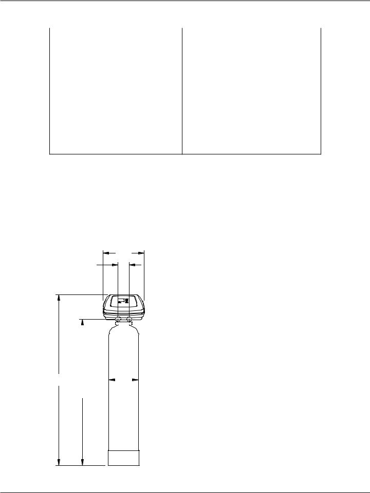
Dimensions
33--3/3/4"”
INLET-
OUTLETINLET - OUTLET
14”" OUTLET INLET
|
|
|
|
NSAIV-10 |
NSAIV-12 |
|
|
|
Nominal Mineral |
10” dia. x |
12” dia. x |
Tank Size |
47” tall |
54” tall |
|
|
|
A |
58-1/8” |
64-1/4” |
|
|
|
B |
49-3/4” |
55-1/2” |
|
|
|
C |
10-1/2” |
12-1/4” |
|
|
|
A |
|
|
|
|
|
|
|
|
|
|
|
|
C |
|
|
|
|
|
|
|
|
|
|
|
||
|
B |
|
|
|
|
|
|
|
FIG. 1
3

Inspect Shipment
The parts required to assemble and install the Air Aspirated Iron Filter are included with the unit. Thoroughly check the water filter for possible shipping damage and parts loss. Also inspect and note any damage to the shipping carton.
Remove and discard (or recycle) all packing materials. To avoid loss of small parts, we suggest you keep the small parts in the parts bag until you are ready to use them.
Bypass Valve |
Installation |
Clips |
O-rings |
|
|
|
Adaptors |
|
FIG. 2 |
|
|
Safety Guides
Follow the installation instructions carefully. Failure to install the filter properly voids the warranty.
Before you begin installation, read this entire manual. Then obtain all the materials and tools you will need to make the installation.
Check local plumbing and electrical codes. The installation must conform to them.
Use only lead-free solder and flux for all sweat-sol- der connections as required by state and federal codes.
Use care when handling the filter. Do not turn upside down, drop, or set on sharp protrusions.
Do not locate the filter where freezing temperatures occur. Do not attempt to filter water over 120°F. Freezing, or hot water damage voids the warranty.
Avoid installing in direct sunlight. Excessive sun heat may cause distortion or other damage to non-metallic parts.
The filter requires a minimum water flow of 5 gallons per minute at the inlet for backwash.
Recommended maximum allowable inlet water pressure is 80 psi. Use a pressure reducing valve if necessary. Be sure the addition of a pressure reducing valve will not reduce the flow to less than the 5 gallons per minute needed for backwash.
The filter works on 24V DC electrical power, supplied by a direct plug-in power supply (included). Be sure to use the included power supply, and plug it into a nominal 120V, 60 Hz household outlet that is in a dry location only, grounded and properly protected by an overcurrent device such as circuit breaker or fuse. This system is not intended to be used for treating water that is microbiologically unsafe or of unknown quality without adequate disinfection before or after the system.
European Directive 2002/96/EC requires all electrical and electronic equipment to be disposed of according to Waste Electrical and Electronic Equipment (WEEE) requirements. This directive or similar laws are in place nationally and can vary from region to region. Please refer to your state and local laws for proper disposal of this equipment.
4

Before Starting Installation
WHERE TO INSTALL THE FILTER
= Place the filter as close as possible to the pressure tank (well system) or water meter (city water).
= Place the filter as close as possible to a floor drain, or other acceptable drain point (laundry tub, sump, standpipe, etc.). CAUTION: Drain water exits the hose at a fast flow rate, and at water system pressure. Be sure the hose is fastened in some manner to prevent ”whipping” and splashing to prevent water damage to surrounding area.
= Connect the filter to the main water supply pipe UPSTREAM OF the water heater. DO NOT RUN HOT WATER THROUGH THE FILTER. The temperature of water passing through the filter must be less than 120°F.
= Keep outside faucets on unfiltered water to conserve filtering capacity.
= Do not install the filter in a place where it could freeze. Damage caused by freezing is not covered by the warranty.
= Put the filter in a place water damage is least likely to occur if a leak develops. The manufacturer will not repair or pay for water damage.
= A 120V, 60 Hz electrical outlet, to plug the included power supply into, is needed near the filter. Be sure the electrical outlet and power supply are in an inside location, to protect from wet weather.
= If installing in an outside location, you must take the steps necessary to assure the filter, installation plumbing, wiring, etc., are as well protected from the elements, contamination, vandalism, etc., as when installed indoors.
= Keep the filter out of direct sunlight. The sun's heat may soften and distort plastic parts.
TOOLS, PIPE & FITTINGS,
OTHER MATERIALS YOU WILL NEED
= Plastic inlet and outlet fittings included with the filter allow water flow equivalent to 1 inch nominal pipe. To maintain full valve flow, 1” pipes to and from the filter fittings are recommended. Do not reduce the pipes to less than 3/4” size.
= Use copper, brass or PEX plastic pipe and fittings. = ALWAYS install the included check valve on the
INLET pipe, immediately upstream of the filter. = ALWAYS install the included bypass valve, or 3 shut-off valves. Bypass valves let you turn off water to the filter for repairs if needed, but still
have water available to the house pipes.
= Drain hose 5/8” inside diameter minimum, with a garden hose connection on one end, is needed for the valve drain. See step 5 on page 8.
= If a rigid valve drain is needed, to comply with plumbing codes, you can buy the parts needed (see page 6) to connect a 5/8” minimum copper tubing drain.
PLAN HOW YOU WILL INSTALL THE FILTER
You must first decide how to run in and out pipes to the filter. Look at the house main water pipe at the point where you will connect the filter. Is the pipe soldered copper, glued plastic, or threaded brass/galvanized? What is the pipe size?
Now look at the typical installation illustration on page 6. Use it as a guide when planning your particular installation. Be sure to direct incoming, unfiltered water to the filter valve inlet fitting. The valve ports are marked IN and OUT.
5

Typical Installation Illustrations
INSTALLATION USING INCLUDED BYPASS VALVE
Filtered |
MAI |
|
N W |
Water OUT |
AT |
ER PIPE |
Unfiltered
Water IN
CROSS-OVER
Use if water supply flows from the left. Include single or 3-valve bypass.
UNFILTERED |
FILTERED |
|
WATER |
||
WATER |
||
|
||
FROM FILTER |
TO FILTER |
|
OUTLET |
INLET |
120V, 60 Hz Outlet
Unfiltered Water |
INSTALLATION USING 3-VALVE BYPASS |
||||||
|
|
MAI |
|
|
|||
|
|
|
|
|
|
||
to Outside Faucets |
|
|
|
N |
WA |
|
|
|
|
|
|
|
|
TER PI |
|
|
|
For filtered water SERVICE: |
|
|
|
PE |
|
1” NPT |
|
|
|
|
|
||
|
-Open the inlet and outlet |
|
|
|
|
||
Female Adaptor (2) |
|
BYPASS |
|
||||
valves |
|
|
|
||||
not included |
|
|
|
|
|||
|
|
|
|
Valve |
|
||
|
|
|
|
|
|
||
1” NPT Installation |
For unfiltered BYPASS: |
|
OUTLET |
|
|
|
|
-Close the inlet and outlet |
|
|
INLET |
||||
Adaptor (2)* |
|
Valve |
|
|
|||
|
|
valves |
|
|
|
|
Valve |
O-Ring Seal (2)* |
|
|
|
|
|
||
-Open the bypass valve |
|
|
|
|
|
||
Bypass Valve* |
|
|
1” NPT |
|
|
|
|
Female Adaptor (2) |
|
|
|
||||
|
|
|
|
|
|||
Clip (4)* |
* Included with filter - Pipe and |
not included |
|
|
|
||
|
|
|
|
|
|||
|
|
|
|
|
|
||
|
fittings supplied by installer. |
|
|
|
|
|
|
|
|
|
|
|
Clip (2)* |
|
|
Valve |
|
|
|
1” NPT Installation |
|
|
INLET |
|
|
|
Adaptor (2)* |
|
|
|
|
|
O-Ring Seal (2)* |
||
|
|
FIG. 3 |
|
Valve |
FIG. 4 |
|
|
|
|
INLET |
|||
Drain |
|
CONNECTING A RIGID VALVE DRAIN TUBE |
||||
Fitting |
Pull out for |
|||||
To adapt a copper tube to the filter, buy a compression fitting (garden hose thread to |
||||||
|
filtered water |
5/8” I.D. minimum tube and necessary tubing from your local hardware store. |
||||
|
“Service” |
|
|
|
|
|
|
|
|
|
Adaptor, garden hose |
||
|
|
|
|
thread to compression |
||
|
Push in for |
Clip |
|
|
5/8” I.D. |
|
|
Bypass |
Drain Fitting |
|
|||
|
|
|
|
(minimum) |
||
|
|
|
|
|
copper tube |
|
Valve |
|
|
|
|
Drain |
|
To standpipe, sump, laundry |
|
|
Hose |
|
tub or other suitable drain. |
|
|
|
1-1/2” |
1-1/2”” |
SUMP |
1-1/2” |
|
Air Gap |
Air Gap |
Air Gap |
|
Valve |
|
|
|
STAND |
|
LAUNDRY |
|
PIPE |
|
Drain |
|
|
||
|
|
|
||
Hose |
FLOOR |
TUB |
|
FIG. 5 |
|
DRAIN |
|
1-1/2” Air Gap |
|
|
|
6 |
|
|
 Loading...