

Page 1
Designed, Engineered &
Assembled in the U.S.A.
OWNER’S MANUAL
How to install, operate
and maintain your
Models
IDP30S Water Softener
IDP40S Water Softener
IDP40CC
& Chlorine Water Conditioner
IDP50CC
& Chlorine Water Conditioner
Models IDP30S & IDP40S tested and certified by
NSF International against NSF/ANSI Standard 44
for hardness reduction and efficiency and the
reduction of barium and radium 226/228,
and certified to NSF/ANSI Standard 372.
Models IDP30S & IDP40S tested and certified by
the Water Quality Association against CSA B483.1.
*
Chloramine
*
Chloramine
Ù Models IDP40CC & IDP50CC have not been
tested or certified by NSF International or the
Water Quality Association.
Manufactured by
Ecodyne Water Systems
1890 Woodlane Drive
Woodbury, MN 55125
7371046 (Rev. A 6/5/18)
Page 2

Table of Contents, Unpacking & Safety Guides
TABLE OF CONTENTS Page
Specifications . . . . . . . . . . . . . . . . . . . . . . . . . . . . . . . 3
Performance Claims & Dimensions . . . . . . . . . . . . . . 4
efore Starting Installation . . . . . . . . . . . . . . . . . . . . 5
B
Typical Installation Illustrations . . . . . . . . . . . . . . . . . 6
Installation . . . . . . . . . . . . . . . . . . . . . . . . . . . . . . 7-10
Sanitizing Procedure . . . . . . . . . . . . . . . . . . . . . . . . 10
Setup Procedure . . . . . . . . . . . . . . . . . . . . . . . . . . . 11
Programming the Water Softener . . . . . . . . . . . . 12-25
Wiring Schematic . . . . . . . . . . . . . . . . . . . . . . . . . . . 24
Adding Salt . . . . . . . . . . . . . . . . . . . . . . . . . . . . . . . 26
Routine Maintenance . . . . . . . . . . . . . . . . . . . . . 26-27
Service Information . . . . . . . . . . . . . . . . . . . . . . 23-24
Troubleshooting . . . . . . . . . . . . . . . . . . . . . . . . . 28-31
Repair Parts . . . . . . . . . . . . . . . . . . . . . . . . . . . . 32-37
Warranty . . . . . . . . . . . . . . . . . . . . . . . . . . . . . . . . . 38
UNPACKING
Models IDP30S, IDP40S and IDP40CC are shipped
from the factory in one carton. The carton also includes
a bag of small parts needed to assemble and install the
unit.
Model IDP50CC is shipped from the factory in two cartons. One contains the resin tank/controller assembly,
plus a bag of small parts needed to assemble and
install the unit. The other carton contains the assembled brine tank.
Thoroughly check the water softener for possible shipping damage and parts loss. Also inspect and note any
damage to the shipping carton.
Remove and discard (or recycle) all packing materials.
To avoid loss of small parts, we suggest you keep the
small parts in the parts bag until you are ready to use
them.
SAFETY GUIDES
Follow the installation instructions carefully. Failure to
install the water filtration system properly voids the
warranty.
Before you begin installation, read this entire manual.
Then, obtain all the materials and tools you will need to
make the installation.
Check local plumbing and electrical codes. The
installation must conform to them.
Use only lead-free solder and flux for all sweat-solder
connections, as required by state and federal codes.
Use care when handling the water filtration system. Do
not turn upside down, drop, or set on sharp protrusions.
Do not locate the water filtration system where freezing
temperatures occur. Do not attempt to treat water over
120°F. Freezing, or hot water damage voids the
warranty.
Avoid installing in direct sunlight. Excessive sun heat
may cause distortion or other damage to non-metallic
parts.
The water filtration system requires a minimum water
pressure of 30 psi at the inlet. Maximum allowable
inlet water pressure is 125 psi. If daytime pressure is
over 80 psi, nighttime pressure may exceed the maximum. Use a pressure reducing valve if necessary
(Adding a pressure reducing valve may reduce the flow).
The water filtration system works on 24V DC electrical
power, supplied by a direct plug-in power supply
(included). Be sure to use the included power supply,
and plug it into a nominal 120V, 60 Hz household outlet
that is in a dry location only, grounded and properly
protected by an overcurrent device such as circuit
breaker or fuse.
This system is not intended to be used for treating water
that is microbiologically unsafe or of unknown quality
without adequate disinfection before or after the system.
European Directive 2002/96/EC requires all
electrical and electronic equipment to be disposed of according to Waste Electrical and
Electronic Equipment (WEEE) requirements.
This directive or similar laws are in place
nationally and can vary from region to region.
Please refer to your state and local laws for
proper disposal of the equipment.
2
Page 3
Specifications
These models are efficiency rated. The efficiency rating is valid only at the minimum salt dose and the service flow
rate. The softeners have a demand initiated regeneration (D.I.R) feature that complies with specific performance
pecifications intended to minimize the amount of regenerant brine and water used in their operation.
s
hese softeners have a rated softener efficiency of not less than 3,350 grains of total hardness exchange per pound
T
of salt (based on sodium chloride) and shall not deliver more salt than their listed rating or be operated at a sus-
ained maximum service flow rate greater than their listed rating. These softeners have been proven to deliver soft
t
water for at least ten continuous minutes at the rated service flow rate. The rated salt efficiency is measured by laboratory tests described in NSF/ANSI Standard 44. These tests represent the maximum possible efficiency that the
system can achieve. Operational efficiency is the actual efficiency after the system has been installed. It is typically
less than the rated efficiency, due to individual application factors including water hardness, water usage, and other
contaminants that reduce a softener's capacity.
While testing was performed under standard laboratory conditions, actual performance of the system may vary
based on local water conditions.
SPECIFICATIONS
Model
Model Code ID30S ID40S ID40C ID50C
Rated Softening Capacity
(grains @ lb. salt dose)
Rated Efficiency
(grains / lb. @ minimum salt dose)
Water Used During Regeneration @
Minimum Salt Dose
Amount of High Capacity Resin 0.79 cu. ft. 1.13 cu. ft. 1.13 cu. ft. 1.56 cu. ft.
Amount of Catalytic Carbon ––0.40 cu. ft. 0.57 cu. ft.
Amount of Gravel –––12 lbs.
Service Flow Rate 7.2 gpm 8.0 gpm 4.0 gpm 5.0 gpm
Pressure Drop at Rated Service Flow 15.0 psig 8.5 psig 10.0 psig 10.0 psig
Intermittent Flow @ 15 psi p
Intermittent Flow @ 30 psi p
Water Supply Maximum Hardness 50 gpg 65 gpg 65 gpg 85 gpg
Water Supply Maximum
Clear Water Iron ¢
Min. - Max. Water Supply Pressure u
Min. - Max. Water Supply Temperature 40 - 120 °F
Minimum Water Supply Flow Rate 3 gpm
Max Drain Flow Rate 2.0 gpm
IDP30S IDP40S
12,000 @ 2.4
25,600 @ 7.5
30,600 @ 12.6
5,090 @ 2.4 4,950 @ 2.4 4,980 @ 2.4 5,090 @ 3.3
2.5 gal. /
1,000 grains
7.2 gpm 11.7 gpm 15.0 gpm 15.0 gpm
11.0 gpm 18.1 gpm 21.0 gpm 21.0 gpm
6 ppm 8 ppm 8 ppm 10 ppm
11,800 @ 2.4
31,600 @ 9.0
40,000 @ 15.5
3.1 gal. /
1,000 grains
20 - 125 psi
IDP40CC
11,800 @ 2.4
31,600 @ 9.0
40,000 @ 15.5
4.1 gal. /
1,000 grains
* IDP50CC*
16,600 @ 3.3
44,300 @ 12.3
56,300 @ 21.3
4.5 gal. /
1,000 grains
p Intermittent flow rate does not represent the maximum service flow rate used for determining the unit’s rated capacity
and efficiency. Continuous operation at flow rates greater than the service flow rate may affect capacity and efficiency
performance.
¢ Capacity to remove clear water iron is substantiated by independent laboratory test data. State of Wisconsin requires
additional treatment if water supply contains greater than 5 ppm clear water iron.
u Canada working pressure limits: 1.4 - 7.0 kg/cm².
Ù Models IDP40CC & IDP50CC have not been tested or certified by NSF International or the Water Quality Association.
These units conform to NSF/ANSI 44 for the specific performance claims as verified and substantiated by test data.
3
Page 4
FRONT VIEWSIDE VIEW
IN - OUT
TOP VIEW
14"
14"
IN
OUT
A
16-1/4"
16"
36-9/16"
32"
BRINE TANK
B
C
Performance Claims & Dimensions
PERFORMANCE CLAIMS
est parameters include: pH = 7.5 ±0.5
T
flow rate = 7.5 gpm
dynamic pressure = 35 ±5 psig
Models IDP40CC & IDP50CC have not been tested or certified by NSF International or the Water Quality Association.
Contaminant
Barium 10 ±10% mg/L 2.0 mg/L
Radium 226/228 25 pCi/L 5 pCi/L
MODELS IDP40CC & IDP50CC PERFORMANCE CLAIM
Substance
Chloramines 3 mg/L >70% @ 10 gpm for 34,000 gal.*
Influent
Challenge Level
Reduction Requirement
* From manufacturer’s test data.
Influent
Challenge Level
Maximum Allowable
Product Water Level
IN
C
OUT
IN - OUT
14”
TOP VIEW
14”
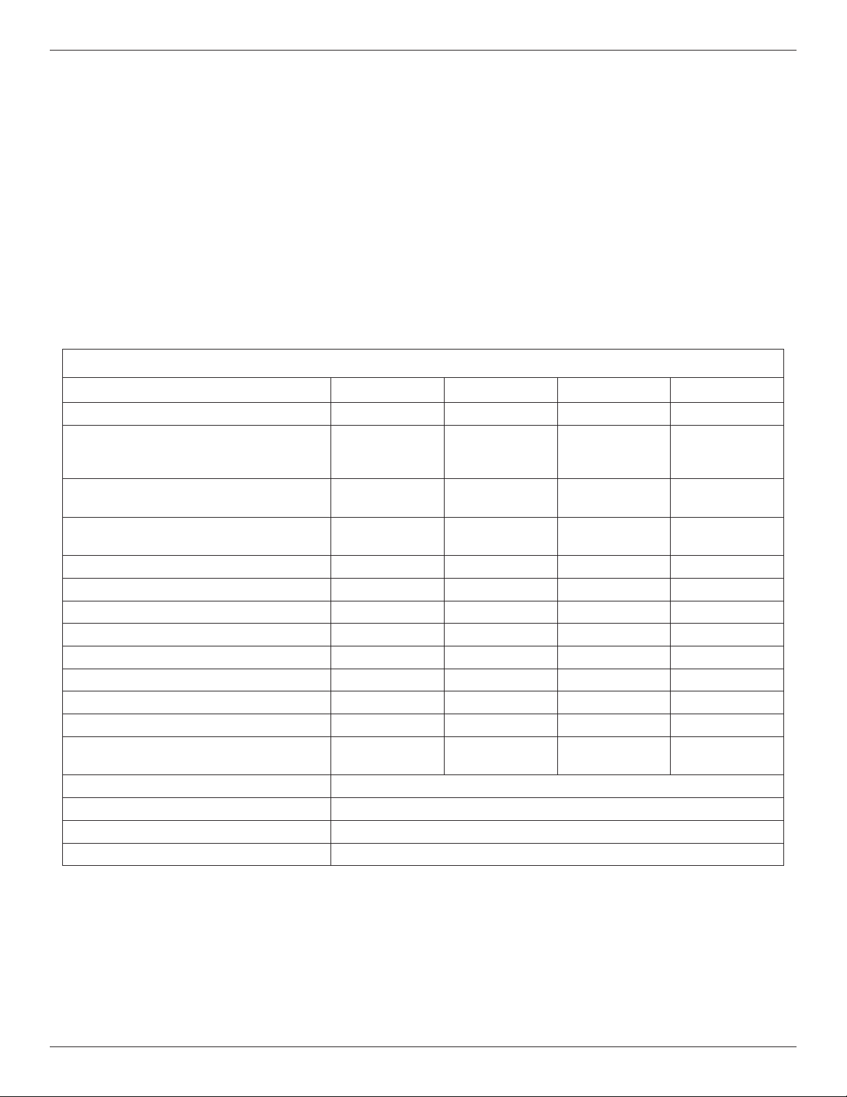
Model
IDP30S 8” dia. x 40” 48-3/4” 42“ 3-3/8“
IDP40S
IDP40CC
IDP50CC 12” dia. x 54” 62-1/2” 55-3/4” 3-3/4“
Nominal Resin
Tank Size
10” dia. x 47” 56-3/4“ 50” 3-3/4“
DimensionADimensionBDimension
C
16”
16-1/4”
A
B
SIDE VIEW FRONT VIEW
4
BRINE TANK
36-9/16”
32”
FIG. 1
Page 5
Before Starting Installation
WHERE TO INSTALL THE SOFTENER
= To soften all water in the home, install the water
softener close to the water supply inlet, upstream
of all other plumbing connections, except outside
water pipes. Outside faucets should remain on
hard water to conserve salt and softening capacity.
= Place the softener near a floor drain, or other
acceptable drain point (laundry tub, sump, standpipe, etc.) to carry away regeneration discharge
water.
= Connect the softener to the main water supply
pipe UPSTREAM OF the water heater. DO NOT
RUN HOT WATER THROUGH THE SOFTENER.
The temperature of water passing through the softener must be less than 120°F.
= Do not install the softener in a place where it could
freeze. Damage caused by freezing is not covered by the warranty.
= Put the softener in a place water damage is least
likely to occur if a leak develops. The manufacturer will not repair or pay for water damage.
= A 120V, 60 Hz electrical outlet, to plug the included
power supply into, is needed near the softener.
Be sure the electrical outlet and power supply are
in an inside location, to protect from wet weather.
= If installing in an outside location, you must take
the steps necessary to assure the softener, installation plumbing, wiring, etc., are as well protected
from the elements, contamination, vandalism, etc.,
as when installed indoors.
= Keep the softener out of direct sunlight. The sun's
heat may soften and distort plastic parts.
TOOLS, PIPE & FITTINGS,
OTHER MATERIALS YOU WILL NEED
= ALWAYS install a single bypass valve, or a 3-valve
bypass system. Bypass valves let you turn off water
to the softener for repairs if needed, but still have
water available to the house pipes.
= Plastic inlet and outlet fittings are included with the
softener, which allow water flow equivalent to 1 inch
nominal pipe. To maintain maximum valve flow, 1”
pipes to and from the softener fittings are recommend ed. Do not reduce the pipes to less than 3/4” size.
= Use copper, brass or PEX plastic pipe and fittings.
= Drain hose, 1/2” inside diameter minimum, is needed
for the valve drain.
= If a rigid valve drain is needed, to comply with
plumbing codes, you can buy the parts needed to
connect a 1/2” minimum copper tubing drain.
NOTE: The Commonwealth of Massachusetts plumbing
code 248-CMR shall be adhered to. A licensed plumber
shall be used for this installation.
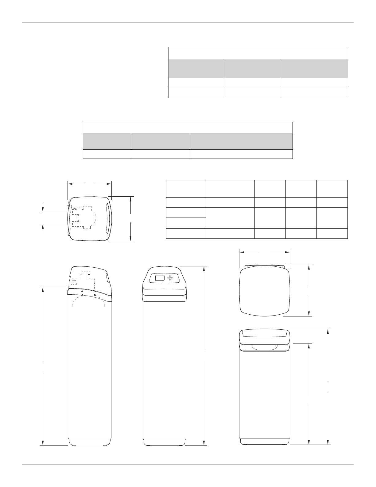
SINGLE BYPASS VALVE
Pull out for “Service”
(Soft water)
Push in for
“Bypass”
FIG. 2
Cold Water
to House
Hot Water
to House
THE PROPER ORDER TO INSTALL WATER TREATMENT EQUIPMENT
Untreated Water to
Outside Faucets
Water
Heater
Water
Softener
Optional
Sediment
Filter
Pressure
5
City Water Supply
Tank
Well Water Supply
OR
Well
Pump
FIG. 3
Page 6
Typical Installation Illustrations
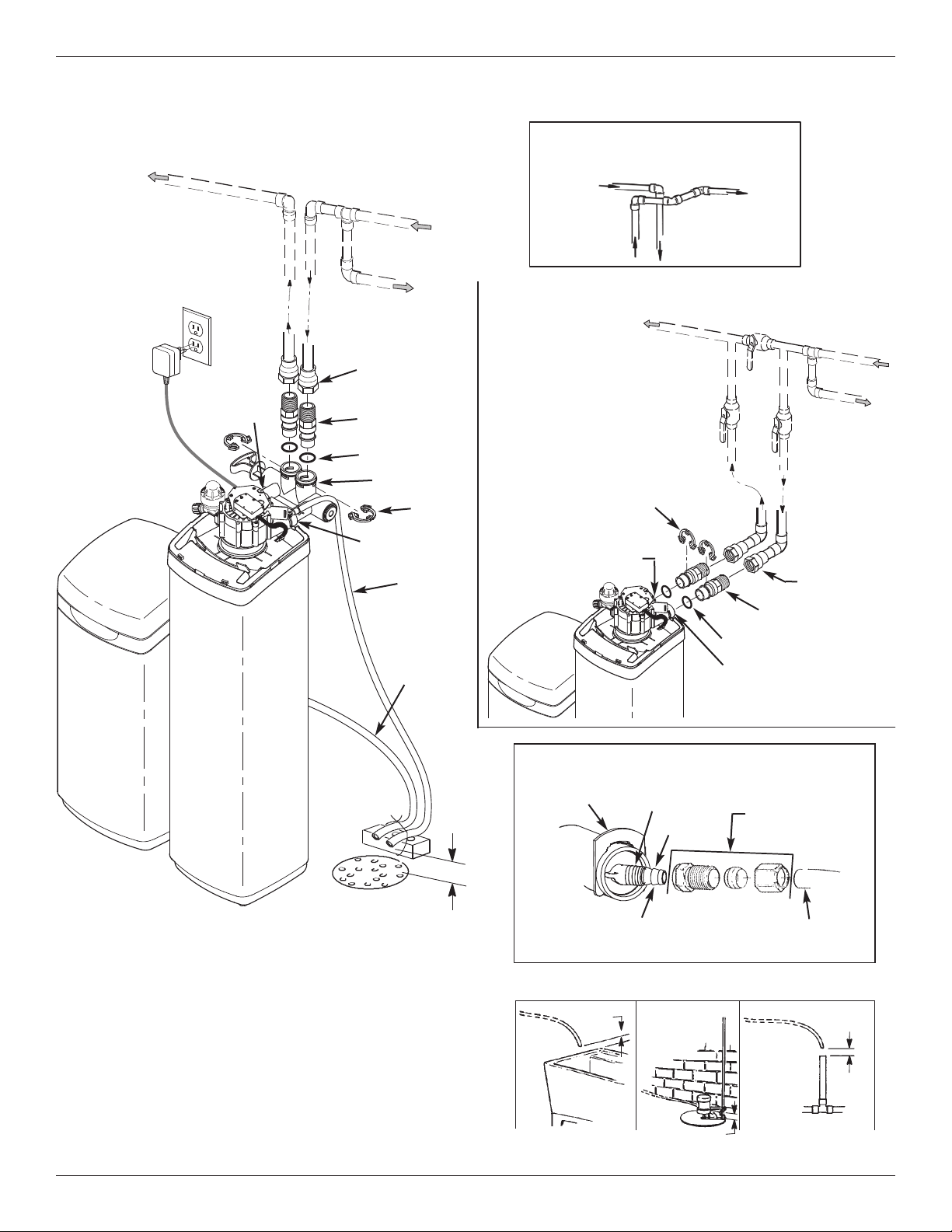
INSTALLATION USING SINGLE BYPASS VALVE
Soft Water
OUT
20V,
1
60 Hz
Outlet
M
A
OUTLET
IN
WAT
E
R
P
IP
E
Hard Water to
Outside Faucets
1” NPT
Female Adaptor (2)
not included
1” NPT Installation
Adaptor (2)*
O-Ring Seal (2)*
Bypass Valve
INLET
Brine Tank
Overflow
Hose**
Clip (2)*
Valve
Drain
Hose
Hard
Water IN
CROSS-OVER
Use if water supply flows from the left.
Include single or 3-valve bypass.
SOFT
ATER
W
ROM SOFTENER
F
UTLET
O
O SOFTENER
T
NLET
I
INSTALLATION USING 3-VALVE BYPASS
M
A
For soft water SERVICE:
-Open the inlet and outlet
valves
For hard water BYPASS:
-Close the inlet and outlet
valves
-Open the bypass valve
Clip (2)*
OUTLET
UTLET
O
Valve
BYPASS
Valve
O-Ring Seal (2)*
INLET
ARD
H
WATER
IN
WAT
ER
PIPE
NLET
I
Valve
1” NPT
Female Adaptor
(2) not included
1” NPT Installation
Adaptor (2)*
FLOOR
Secure Valve Drain Hose
in place over Floor Drain
DRAIN
1-1/2”
Air Gap
*Included with softener - Pipe and fittings supplied by installer.
**Do not connect the water softener valve drain hose to the brine
tank overflow hose.
CONNECTING A RIGID VALVE DRAIN TUBE
Clip
Cut barbs from drain fitting (pull
clip to remove fitting from valve)
1/4 NPT Threads
Barbs
Compression Fitting.
1/4 NPT x 1/2” O.D.
Tube (not included)
1/2” Outside Dia. Copper
Tube (not included)
To standpipe, sump, laundry tub or other suitable drain.
1-1/2”
Air Gap
LAUNDRY
TUB
SUMP
1-1/2” Air Gap
6
1-1/2”
Air Gap
STAND
PIPE
FIG. 4
Page 7

Installation
1. TURN OFF WATER SUPPLY
a. Close the main water supply valve near the well
pump or water meter.
b. Shut off the electric or fuel supply to the water
heater.
c. Open high and low faucets to drain all water from
the house pipes.
2. INSTALL BYPASS VALVE AND/OR
PLASTIC ADAPTORS:
a. If installing a single bypass valve, push the bypass
valve, with lubricated o-ring seals in place, into the
valve inlet and outlet ports (See Figures 4 & 5).
- OR -
b. If installing a 3-valve bypass system, slide plastic
installation adaptors, with lubricated o-ring seals in
place, into the valve inlet and outlet ports (See
Figure 4 & 5).
c. Be sure the turbine support is in place in the valve
outlet, as shown in Figure 6.
d. Snap the two large plastic clips in place on the inlet
and outlet ports, from the top, down (See Figure
7). Be sure they snap into place. Pull on the
bypass valve or plastic adaptors, to make sure
they are held securely in place.
Clips
INLET
Lubricated
O-Rings
Turbine
Clip
OUTLET
Turbine
Turbine
Support
Plastic
nstallation Adaptors
I
(install in softener valve
or bypass valve)
Support
Single
Bypass Valve
Valve
Outlet
Clip
FIG. 5
3. COMPLETE PLUMBING TO AND FROM
THE SOFTENER
Using the “Typical Installation Illustration” on page 6
as a guide, observe all of the following cautions while
you connect inlet and outlet plumbing:
= Be sure incoming, hard water is directed to the
valve INLET port.
= Be sure to install bypass valve(s).
= If making a soldered copper installation, do all
sweat soldering before connecting pipes to the
softener fittings. Torch heat will damage plastic
parts.
= Use pipe joint compound on all external pipe
threads.
= When turning threaded pipe fittings onto plastic fit-
tings, use care not to cross-thread.
= Support inlet and outlet plumbing in some manner
(use pipe hangers) to keep the weight off of the
valve fittings.
O-ring
Cross section of
valve inlet or outlet
Snap clips into place between
INLET
Clip
larger diameter rings
Turn the bypass
valve downward if
connecting to floor
level plumbing
OUTLET
FIG. 6
Bypass valve or
plastic adaptor
FIG. 7
FIG. 8
7
Page 8
round
G
Clamp
Installation
Nut
Brine
ank
T
Brinewell
over
C
rine
B
Tubing
Inlet / Outlet
Pipes
FIG. 9
4. COLD WATER PIPE GROUNDING
The house cold water pipe (metal only) is often used
as a ground for the house electrical system. The 3valve bypass type of installation, shown in Figure 4,
will maintain ground continuity. If you use the plastic
bypass, continuity is broken. To restore the ground,
do either step 4a or 4b following.
a. Use the ground clamp kit (not included) to make a
jumper across the inlet and outlet pipes (See Figure
9).
b. Install a #4 copper wire across the removed section of main water pipe, securely clamping at both
ends – parts not included.
5. INSTALL VALVE DRAIN HOSE
a. Take a length of 1/2” inside diameter hose and
attach to the valve drain fitting, securing it with a
hose clamp (See Figure 4 on page 6).
b. Locate the other end of the hose at a suitable drain
point (floor drain, sump, laundry tub, etc.). Check
and comply with local codes. Refer to Figure 4 if
codes require a rigid pipe drain run.
IMPORTANT: Use high quality, thick wall hose that
will not easily kink or collapse. The
softener will not backwash properly if
water cannot exit this hose during
recharges.
c. Tie or wire the hose in place at the drain point.
Water pressure will cause it to whip during the
backwash portion of the recharge cycle. Also provide an air gap of at least 1-1/2” between the end
of the hose and the drain point. An air gap prevents possible siphoning of sewer water, into the
softener, if the sewer should back up.
d. If raising the drain hose overhead is required to get
to the drain point, do not raise higher than 8 feet
above the floor. Elevating the hose may cause a
back pressure that could reduce backwash flow
and proper resin bed cleaning.
Elbow
Grommet
Screw
Brinewell
Brine
Valve
Slots
FIG. 10
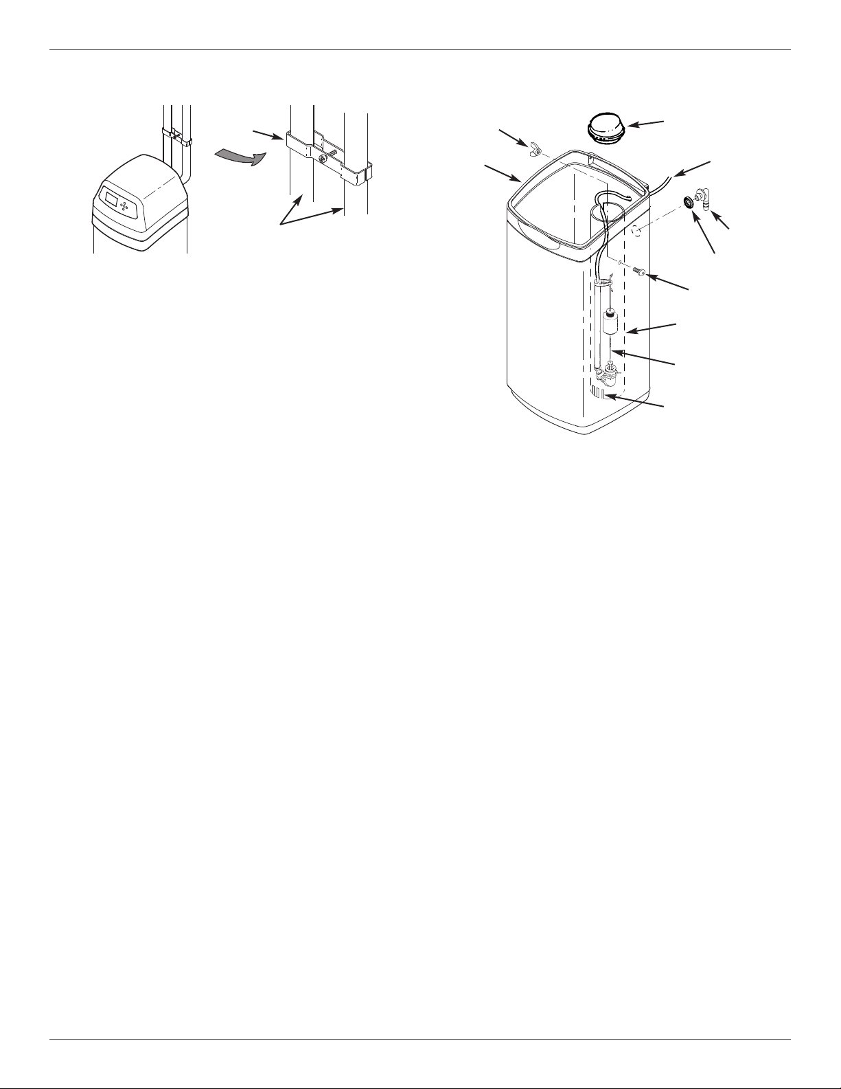
6. BRINE TANK ASSEMBLY
Complete the following steps for Models IDP30S,
IDP40S and IDP40CC. For Model IDP50CC, shipped
with an assembled brine tank, proceed to Step 7.
a. Place the brinewell into position in the brine tank,
with the slots at the bottom, as shown in Figure 10.
Align the mounting hole in the brinewell with the corresponding hole in the tank wall. Then use the screw and
nut from the parts bag to fasten the brinewell in place.
b. Lower the brine valve into the brinewell. Push the
tubing into the brinewell top slot (Fig. 10) and route it
out of the brine tank through the smaller hole in the rear
wall of the brine tank.
c. Install the brinewell cover.
7. INSTALL BRINE TANK OVERFLOW HOSE
This drain is for safety only. If the brine tank should
over-fill with water, the excess is carried to the drain.
a. Take the rubber grommet and hose adaptor elbow
from the parts bag. Push grommet into the corresponding hole in the back wall of the brine tank.
Then insert the larger diameter end of the elbow
through the grommet.
b. Attach a length of 1/2” inside diameter hose to the
drain elbow, installed in the previous step. Use a
hose clamp to hold it in place.
c. Locate the other end of the hose at the drain point.
Do not elevate this hose higher than the elbow on
the brine tank. Do not tee this hose to the valve
drain hose.
8
Page 9

Installation
Ferrule
Nut
Brine Tubing
Brine Tank
Overflow Hose
Valve
Drain Hose
Floor
Drain
1-1/2”
Air Gap
FIG. 11
8. CONNECT BRINE TUBING
a. Route the brine tube out of the brine tank through
the smaller hole in the tank back wall.
b. Connect the brine tube to the nozzle/venturi
assembly using the ferrule nut provided (See
Figure 11).
g. Make sure the softener’s bypass valve is in the
bypass position.
h. Plug in the power supply.
i. Program the electronic controller: Follow the
steps on Page 11 to program the electronic controller with basic operating information, such as time
and water hardness. After completing these steps,
continue with “j. Start a recharge”, below.
j. Start a recharge: From the rolling status screens,
press the SELECT (¡) button to display the Main
menu. Make sure Recharge is highlighted, then
press SELECT (¡). Press DOWN (6) to scroll to
Recharge now, then press SELECT (¡) twice.
You should hear the valve motor run as the softener
begins recharging.
k. Once the unit is in backwash, place bypass
valve(s) into the service position, as follows:
(1) SINGLE BYPASS VALVE: Slowly move the
valve stem toward service position, pausing several times to allow the unit to pressurize slowly.
(2) 3-VALVE BYPASS: Fully close the bypass
valve and open the outlet valve. Slowly open
the inlet valve, pausing several times to allow the
unit to pressurize slowly.
l. Let the softener complete the backwash and fast
rinse cycles (takes 10-12 minutes). When the
recharge cycle ends, the softener valve returns to
the service position.
9. PRESSURE TESTING FOR LEAKS,
PROGRAMMING THE CONTROLLER &
RINSING THE MEDIA
To prevent excessive air pressure in the water
softener and plumbing system, do the following
steps EXACTLY in order:
a. Fully open two or more softened cold water
faucets nearby the water softener.
b. Place the bypass valve(s) in bypass position (See
Figures 2 & 4).
c. Fully open the main water supply valve. Watch
until the flow from the opened faucets becomes
steady, with no spurting or air bubbles.
d. After about three minutes, open a hot water faucet
for one minute, or until all air is expelled.
e. Close all faucets and check your plumbing work for
leaks.
f. Make sure the softener’s valve drain hose is
hooked up and the open end directed to a floor
drain, laundry tub or other suitable type of drain.
10. ADD WATER AND SALT TO THE
BRINE TANK
a. Using a pail or garden hose, add about 3 gallons of
water into the brine tank. DO NOT pour into the
brinewell.
b. Add salt to the brine tank. It is recommended to fill
the brine tank no more than 1/2 full. Level the salt
when finished adding. You can use most water
softener salts, but it must be clean.
Recommended nugget, pellet or coarse solar salts
have less than 1% impurities.
NOTE: See page 26 for additional information on salt.
9
Page 10

Installation & Sanitizing
11. SANITIZING THE WATER SOFTENER
Care is taken at the factory to keep your water softener clean and sanitary. However, during shipping, storage, installing and operating, bacteria could get into
the unit. For this reason, sanitizing as follows is suggested* when installing.
a. Remove the brinewell cover and pour about 1-1/2
oz. (2 to 3 tablespoons) of common household
bleach into the softener’s brinewell. Replace the
brinewell cover.
b. Make sure the bypass valve is in the service posi-
tion.
c. Start a recharge: From the rolling status screens,
press the SELECT (¡) button to display the Main
menu. Make sure Recharge is highlighted, then
press SELECT (¡). Press DOWN (6) to scroll to
Recharge now, then press SELECT (¡) twice.
You should hear the valve motor run as the softener begins recharging. This recharge draws the
sanitizing bleach into and through the softener.
Any air remaining in the unit is purged to the drain.
d. After the recharge has completed, fully open a cold
water faucet, downstream from the softener, and
allow 50 gallons of water to pass through the system. This should take at least 20 minutes. Close
the faucet.
12. RESTART THE WATER HEATER
Turn on the electric or fuel supply to the water heater,
and light the pilot, if applies.
NOTE: The water heater is filled with hard water and,
as hot water is used, it refills with softened water. In
a few days, the hot water will be fully conditioned. To
have fully conditioned hot water immediately, wait
until the recharge (Step 11) is complete, then drain
the water heater until water runs cold.
*NOTE: Sanitizing is recommended by the Water Quality
Association for disinfecting. On some water supplies, they suggest periodic sanitizing.
10
Page 11
Setup Procedure
English
Metric
System units
12:34 PM
Current time
Salt level
4
0.0 PPM
Iron level
Run system
Redo setup
Setup complete!
English
Español
Français
Language
25 Grains
Hardness
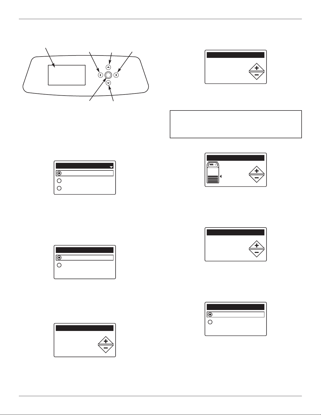
Display
LEFT
Button
SELECT
Button
UP
Button
DOWN
Button
RIGHT
Button
FIG. 12
SETUP PROCEDURE
When the water softener is plugged in for the first time,
a beep sounds and the display briefly shows model
information. Next, a series of “wizard” screens prompts
you to enter basic operating information:
FIG. 13
1. LANGUAGE If the desired language already has a
black dot next to it (See Figure 13), go to Step 2.
Otherwise, press the softener’s DOWN (6) or UP
(5) buttons to scroll to the desired language, then
press the SELECT (¡) button to choose it.
2. Press the SELECT (¡) button to advance to the next
“wizard” screen.
6. Press the SELECT (¡) button.
FIG. 16
7. HARDNESS Press the UP (5) or DOWN (6) but-
tons to set the value of your water’s hardness (See
Figure 16).
NOTE: Do not increase the hardness setting to
compensate for iron in your water. The
electronic control compensates automatically
after you set the iron level in Step 11, below.
8. Press the SELECT (¡) button.
FIG. 17
9. SALT LEVEL Press the UP (5) or DOWN (6) but-
tons to set the salt level (See Figure 17). It should
match the lowest number visible on the brinewell
above the salt.
10. Press the SELECT (¡) button.
3. SYSTEM UNITS If the desired system already has a
black dot next to it (See Figure 14), go to Step 4.
Otherwise, press the DOWN (6) or UP (5) buttons
to scroll to the desired system, then press the
SELECT (¡) button to choose it.
4. Press the SELECT (¡) button.
5. CURRENT TIME Press the DOWN (6) or UP (5)
buttons to set the current time (See Figure 15). Hold
the button down to rapidly advance. Be sure that AM
or PM is correct. If the system units were set to metric in Step 3, the clock will be in 24-hour format.
FIG. 18
11. IRON LEVEL Press the UP (5) or DOWN (6) but-
FIG. 14
tons to set the value for iron in your water (See
Figure 18)
12. Press the SELECT (¡) button. The screen will
show “Setup complete!” (See Figure 19).
FIG. 19
13. If, at this point, you want to go back and make
changes, press the DOWN (6) button to scroll to
FIG. 15
11
Redo setup, then press the SELECT (¡) button
twice to repeat the “wizard” screens.
14. If no changes are desired, make sure Run system
has a black dot next to it (See Figure 19) and press
the SELECT (¡) button. The unit begins normal
operation, described on the next page.
Page 12
0.0 GPM
Water flow
2:34 PM
Salt status (NaCl)
2:34 PM
Water use (gallons)
2:34 PM
Out of salt in
119 days
Recharge status
2:34 PM
Set for automatic
recharge
Today: 121
Daily average: 175
Remaining: 736
Efficiency mode
Max. days between rech...
Auxiliary control
Special features
Effieciency mode
Auxiliary control
Special features
Max. days between
recharges
Programming the Water Softener
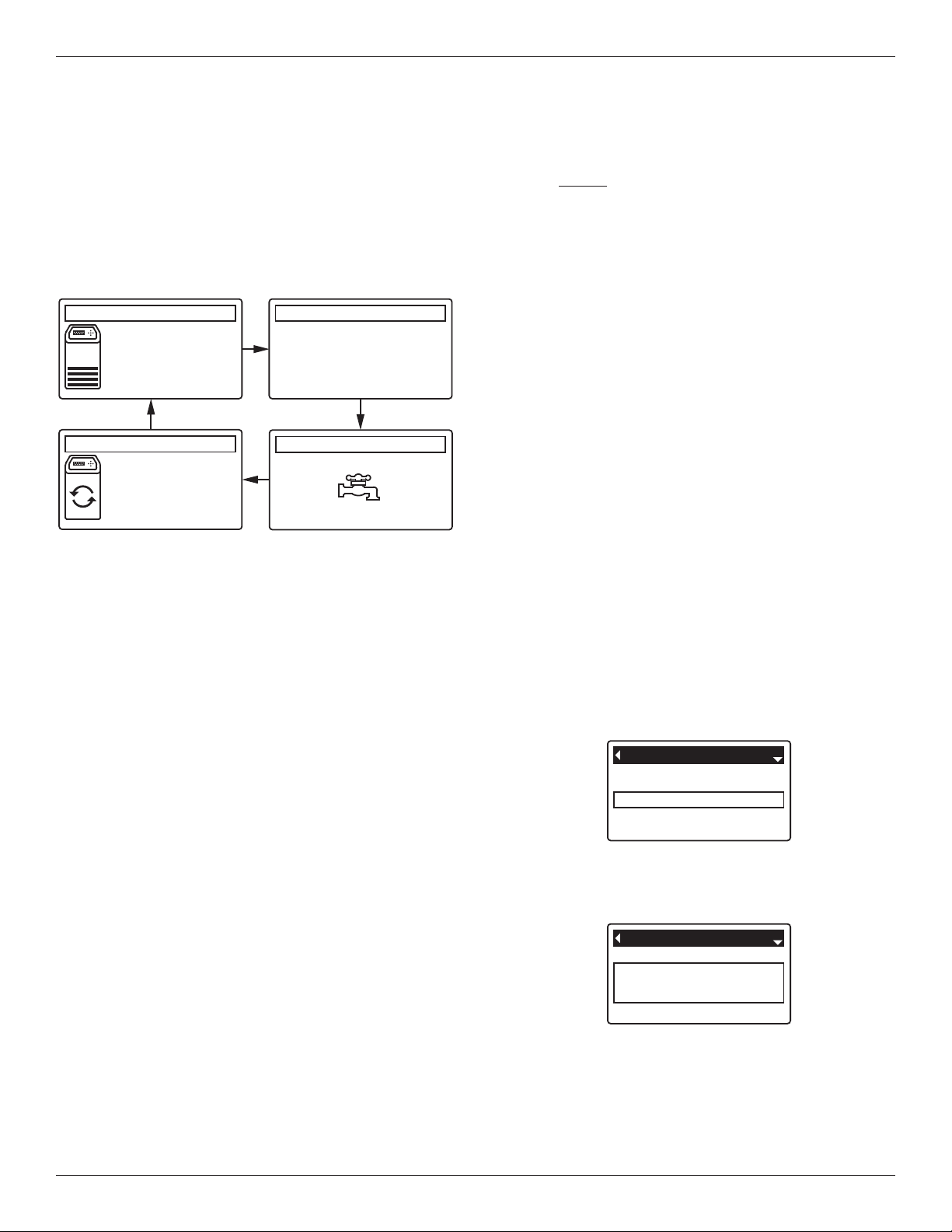
NORMAL OPERATION
SOFTENER STATUS SCREENS
uring normal operation, the water softener’s display
D
shows up to four status screens. Page 18 explains how
ndividual screens can be turned on or off. Each is
i
shown for six seconds, in a rolling sequence (See
Figure 20).
*
*Water remaining before the next recharge.
Pressing the softener’s RIGHT (4) button manually
advances to the next screen in the sequence. Pressing
the LEFT (3) button manually returns to the previous
status screen. If no buttons are pressed for 30 seconds, the automatic rolling sequence resumes.
FIG. 20
OTHER MESSAGES, ALERTS & REMINDERS
The softener status screens described in the previous
section will not be displayed in a rolling sequence when
one of the following items is displayed:
=Recharge status (Displayed during recharges,
showing valve position and time remaining)
=Add salt or Out of salt (See Page 26)
=Current time setting screen instead of status
screens indicates time has been lost, perhaps after
a long power loss. Set the time (See Page 16).
=Service reminder (See Page 24)
=Error detected (Contact your dealer for service)
FLASHING DISPLAY
The softener’s display will flash on and off when one or
more of the following conditions occurs:
=Salt needs to be added
=Time needs to be set (Time has been lost)
=Service is overdue (Service reminder)
=Error condition
The flashing will stop after any key is pressed.
However, it will start again at Midnight if the underlying
condition (e.g. low salt level) has not been addressed.
LONG DISPLAY SCREEN MESSAGES
Most messages in the softener’s display screens are
short enough to be shown as a single line. Longer
messages will be truncated (See Figure 21 for an
example) until you highlight them.
FIG. 21
One second after being highlighted, the viewing box
expands (See Figure 22) to show the entire message.
After three seconds the view resets (Figure 21).
FIG. 22
12
Page 13

Programming the Water Softener
Recharge
Salt settings
Basic settings
Main menu
MAIN MENU
FIG. 23
During normal operation (status screens rolling), press
the softener’s SELECT (¡) button to display the Main
menu (See Figure 23). This menu and its subsidiary
screens are used to control these operations:
=Recharge (See Page 16)
=Salt settings
=Salt level (See Page 15)
=Low salt alarm (See Page 15)
=Salt type (See Page 15)
=Basic settings
=Current time (See Page 16)
=Hardness (See Page 17)
=Iron level (See Page 17)
=Recharge time (See Page 17)
=Rolling screens (See Page 18)
=User preferences
=Language (See Page 18)
=Time format (See Page 19)
=Volume units (See Page 19)
=Hardness units (See Page 19)
=Weight units (See Page 19)
=System information
=Model information (See Page 20)
=Water available (See Page 20)
=Daily avg. water used (See Page 20)
=Water used today (See Page 20)
=Total water used (See Page 20)
=Current water flow (See Page 20)
=Days powered up (See Page 20)
=Last recharge (See Page 20)
=Total recharges (See Page 20)
=Advanced settings
=Cycle times
=Backwash time (See Page 21)
=2nd backwash (On/Off) (See Page 21)
=2nd backwash time (See Page 21)
=Fast rinse time (See Page 21)
=Special features
=Efficiency mode (See Page 22)
=Max. days between recharges (See Page 22)
=Auxiliary control (See Page 23)
=Chemical feed volume* (See Page 23)
=Chemical feed timer* (See Page 23)
=97% feature (See Page 22)
=Service reminder (See Page 24)
=Troubleshooting
=Diagnostics (See Page 25)
=Setup changes (See Page 25)
* Only displayed if Auxiliary control is set to Chemical
feed.
13
Page 14

Programming the Water Softener
Model information
Model: ID30S
Version: T2.3
Hardness
25 grains
Hardness
25 grains
Redo setup
Restore defaults
Cancel
Setup changes
Redo setup
Restore defaults
Cancel
Setup changes
LOCKOUT FEATURE
A “lockout” feature is available to prevent user modification of parameters that affect softener performance.
The unit is shipped from the factory with the lockout
feature off. After programming is complete, the lockout
feature can be turned on to prevent changes to the following:
=Hardness
=Iron level
=Backwash time
=Second backwash (On/Off)
=Second backwash time
=Fast rinse time
=Efficiency mode
=Max days between recharges
=Auxiliary control
=Chemical feed volume
=Chemical feed timer
=97% feature
=Service reminder
=Setup changes
To turn on the lockout feature:
1. From any of the rolling status screens, press the
SELECT (¡) button to display the Main menu.
2. Press the DOWN (6) button to scroll through the
menu options until Advanced settings is highlighted.
3. Press the SELECT (¡) button to display the
Advanced settings menu.
4. Press the DOWN (6) button to scroll through the
menu options until Troubleshooting is highlighted.
5. Press the SELECT (¡) button to display the
Troubleshooting menu.
6. Press the DOWN (6) button to scroll through the
menu options until Setup changes is highlighted.
7. Press the SELECT (¡) button to display the Setup
changes menu (See Figure 24).
FIG. 25
9. Press the SELECT (¡) button.
10. Press the LEFT (3) button three times to return to
the rolling status screens.
When the lockout feature is on, the flashing padlock
icon will appear in any screen that would normally be
used to change a parameter in the list to the left. For
example, the Hardness screen will look like Figure 27,
instead of Figure 26.
FIG. 26
FIG. 27
Another indicator that the lockout feature is on is the
Model Information screen. This screen appears on
power-up, and can also be displayed from the System
Information menu (See Page 20). If the lockout feature
is on, there will be a non-flashing padlock icon in the
upper right corner (See Figure 28).
8. Press the RIGHT (4) button. A flashing padlock icon
will appear, as shown in Figure 25.
FIG. 24
FIG. 28
To turn off the lockout feature:
1-7. Go to the Setup changes screen (Figure 25) by
following Steps 1-7 at left.
8. Press the RIGHT (4) button. The flashing padlock
icon will disappear, as shown in Figure 24.
9. Press the SELECT (¡) button.
10. Press the LEFT (3) button three times to return to
the rolling status screens.
14
Page 15

Programming the Water Softener
Salt level
4
20 days before
empty
Low salt alarm
Recharge
Salt settings
Basic settings
Main menu
Salt level
Low salt alarm
Salt settings
Salt type
L
EVEL
S
ALT
Sodium (NaCl)
Potassium (KCl)
Salt type
SETTING SALT LEVEL
Use this feature when adding salt to the softener.
1. From any of the rolling status screens, press the
SELECT (¡) button to display the Main menu.
2. Press the DOWN (6) button to scroll through the
menu options until Salt settings is highlighted (See
Figure 29).
FIG. 29
3. Press the SELECT (¡) button to display the Salt set-
tings menu (See Figure 30).
FIG. 30
4. Make sure Salt level is highlighted.
5. Press the SELECT (¡) button to display the Salt
level screen (See Figure 31). This screen will not
automatically exit for 15 minutes.
LOW SALT ALARM
Use this feature to program when the electronic control
will display a low salt alarm. The number of days can
be customized, or the feature can be turned off. The
default is 20 days.
1-3. Go to the Salt settings menu by following Steps 1-
3 in “Setting Salt Level” at left.
4. Press the DOWN (6) button to scroll through the
menu options until Low salt alarm is highlighted.
5. Press the SELECT (¡) button to display the Low salt
alarm screen (See Figure 32).
FIG. 32
6. Press the UP (5) or DOWN (6) buttons to change
the number of days. Set the number of days to provide enough time to purchase salt and avoid running
into hard water. Setting the number of days below 1
turns the alarm feature off.
7. Press the SELECT (¡) button. The display will go
back to the Salt settings menu.
8. Press the LEFT (3) button twice to return to the
rolling status screens.
Salt
Level
6. After adding and leveling salt, observe the numbered
scale on the brinewell (See Figure 31). Press UP (5)
or DOWN (6) to change the salt level to match the
lowest number visible above the salt.
7. Press the SELECT (¡) button. The display will go
back to the Salt settings menu (Figure 30).
8. Press the LEFT (3) button twice to return to the
rolling status screens. It will also exit automatically if
no buttons are pressed for four minutes.
SETTING SALT TYPE
Brinewell
Numbers
FIG. 31
Use this feature to program the electronic control with
which type of salt is used. The default is NaCl.
Selecting KCl increases fill time 25% and brine/slow
rinse times 12%.
1-3. Go to the Salt settings menu by following Steps 1-
3 in “Setting Salt Level” at left.
4. Press the DOWN (6) button to scroll through the
menu options until Salt type is highlighted.
5. Press the SELECT (¡) button to display the Salt type
menu (See Figure 33).
FIG. 33
6. If the desired salt type already has a black dot next
to it (See Figure 33), go to Step 7. Otherwise, press
the softener’s DOWN (6) or UP (5) buttons to scroll
to the other salt type, then press SELECT (¡) to
choose it.
7. Press the SELECT (¡) button. The display will go
back to the Salt settings menu.
8. Press the LEFT (3) button twice to return to the
rolling status screens.
15
Page 16

Programming the Water Softener
Recharge
Salt settings
Basic settings
Main menu
Current time
Hardness
Iron level
Basic settings
Current time
12:34 PM
Automatic
Recharge now
Schedule
Recharge
Recharge
Salt settings
Basic settings
Main menu
Recharge status
Time left: 118:32
Cycle: Fill
(Right key press advances
cycle)
RECHARGING THE SOFTENER
This feature may be used to assure an adequate supply
of softened water at times of unusually high water use.
For example, if you have guests and the “Water available” screen (See Page 20) is at or below 50%, you
could deplete softened water capacity before the next
automatic recharge. Initiating a manual recharge will
restore 100% softened water capacity after complete.
1. From any of the rolling status screens, press the
SELECT (¡) button to display the Main menu.
FIG. 34
2. Make sure Recharge is highlighted (See Figure 34).
3. Press the SELECT (¡) button to display the
Recharge menu (See Figure 35).
SETTING THE CURRENT TIME
When the softener’s electronic control is first powered
up, a “wizard” screen prompts you to set the current
time (See Page 11). To change the time at a later date,
such as after a long power loss:
1. From any of the rolling status screens, press the
SELECT (¡) button to display the Main menu.
2. Press the DOWN (6) button to scroll through the
menu options until Basic settings is highlighted
(See Figure 37).
FIG. 37
3. Press the SELECT (¡) button to display the Basic
settings menu (See Figure 38).
FIG. 35
4. If the desired option already has a black dot next to it
(See Figure 35), go to Step 5. Otherwise, press the
DOWN (6) or UP (5) buttons to scroll to the desired
option, then press SELECT (¡) to choose it.
=Automatic cancels a manually scheduled recharge
(if it has not already begun) and lets the electronic
control determine when to recharge next.
=Recharge now begins a recharge immediately
after the SELECT (¡) button is pushed again in Step
5.
=Schedule sets a recharge to begin at the preset
recharge time (set according to the instructions on
Page 17).
5. Press the SELECT (¡) button. If Recharge now is
selected, the display immediately goes to the
Recharge status screen (See Figure 36). If
Automatic or Schedule are selected, the display
goes back to the Main menu (Figure 34).
FIG. 38
4. Make sure Current time is highlighted.
5. Press the SELECT (¡) button to display the Current
time screen (See Figure 39).
FIG. 39
6. Press the UP (5) or DOWN (6) buttons to change
the time. Hold the button down to rapidly advance.
Be sure that AM or PM is correct (unless softener is
set for a 24-hour clock).
7. Press the SELECT (¡) button. The display will go
back to the Basic settings menu (Figure 38).
8. Press the LEFT (3) button twice to return to the
rolling status screens.
6. Press the LEFT (3) button (twice from the Recharge
status screen) to return to the rolling status screens.
FIG. 36
16
Page 17

Programming the Water Softener
Hardness
Iron level
Recharge time
Basic settings
Recharge time
2:00 AM
Recharge
Salt settings
Basic settings
Main menu
Iron level
0.0 PPM
Hardness
25 grains
SETTING RECHARGE TIME
When the softener’s electronic control is first powered
up, the default time for starting an automatic recharge is
2:00 a.m. This is a good time in most households
because water is not being used. To change this time:
1. From any of the rolling status screens, press the
SELECT (¡) button to display the Main menu.
2. Press the DOWN (6) button to scroll through the
menu options until Basic settings is highlighted
(See Figure 40).
3. Press the SELECT (¡) button to display the Basic
settings menu (See Figure 41).
4. Press the DOWN (6) button to scroll through the
menu options until Recharge time is highlighted.
5. Press the SELECT (¡) button to display the
Recharge time screen (See Figure 42).
6. Press the UP (5) or DOWN (6) buttons to change
the recharge time in 1 hour increments. Hold the
button down to rapidly advance. Be sure that AM or
PM is correct (unless softener is set for a 24-hour
clock).
7. Press the SELECT (¡) button. The display will go
back to the Basic settings menu (Figure 41).
8. Press the LEFT (3) button twice to return to the
rolling status screens.
FIG. 40
FIG. 41
FIG. 42
SETTING HARDNESS
When the softener’s electronic control is first powered
up, a “wizard” screen prompts you to enter your water’s
hardness (See Page 11). To change it:
1-3. Go to the Basic settings menu by following Steps
1-3 in “Setting Recharge Time” at left.
4. Press the DOWN (6) button to scroll through the
menu options until Hardness is highlighted.
5. Press the SELECT (¡) button to display the
Hardness screen (See Figure 43).
FIG. 43
6. Press the UP (5) or DOWN (6) buttons to set the
value for your water’s hardness. Hold the button
down to rapidly advance.
NOTE: Do not increase the hardness setting to
compensate for iron in your water. The
electronic control compensates automatically
after you set the iron level, below.
7. Press the SELECT (¡) button. The display will go
back to the Basic settings menu.
8. Press the LEFT (3) button twice to return to the
rolling status screens.
SETTING IRON LEVEL
When the softener’s electronic control is first powered
up, a “wizard” screen prompts you to enter your water’s
iron level (See Page 11). To change:
1-3. Go to the Basic settings menu by following Steps
1-3 in “Setting Recharge Time” at left.
4. Press the DOWN (6) button to scroll through the
menu options until Iron level is highlighted.
5. Press the SELECT (¡) button to display the Iron
level screen (See Figure 44).
FIG. 44
6. Press the UP (5) or DOWN (6) buttons to set the
value for iron in your water. Hold the button down to
rapidly advance.
7. Press the SELECT (¡) button. The display will go
back to the Basic settings menu.
8. Press the LEFT (3) button twice to return to the
rolling status screens.
17
Page 18

Programming the Water Softener
R
echarge
Salt settings
Basic settings
Main menu
Iron level
Recharge time
Rolling screens
Basic settings
Salt status
Water use
Flow rate
Rolling screens
Salt settings
Basic settings
User preferences
M
ain menu
Language
Time format
Volume units
User preferences
English
Español
Français
Language
MODIFYING ROLLING SCREENS
During normal softener operation, up to five status
screens are shown in sequence (See “Softener Status
Screens” on Page 12). When the softener’s electronic
control is first powered up, the default is to show all
four. You can turn on/off individual screens*:
1. From any of the rolling status screens, press the
SELECT (¡) button to display the Main menu.
2. Press the DOWN (6) button to scroll through the
menu options until Basic settings is highlighted
(See Figure 45).
FIG. 45
3. Press the SELECT (¡) button to display the Basic
settings menu (See Figure 46).
SETTING THE LANGUAGE
When the softener’s electronic control is first powered
up, a “wizard” screen prompts you to set the language
(See Page 11). To change the language:
1. From any of the rolling status screens, press the
SELECT (¡) button to display the Main menu.
2. Press the DOWN (6) button to scroll through the
menu options until User preferences is highlighted
(See Figure 48).
FIG. 48
3. Press the SELECT (¡) button to display the User
preferences menu (See Figure 49).
FIG. 49
4. Press the DOWN (6) button to scroll through the
menu options until Rolling screens is highlighted.
5. Press the SELECT (¡) button to display the Rolling
screens menu (See Figure 47).
6. Press the DOWN (6) or UP (5) buttons to scroll
through the list. Items with a black square next to
them will be displayed during normal operation.
7. To un-select a screen, make sure its name is highlighted in a box. Then press the SELECT (¡) button.
The black square will disappear. Pressing SELECT
(¡) again makes the black square reappear and reselects the highlighted item. At least one screen
must be selected/highlighted.
8. When selections are complete, exit this menu by
pressing the LEFT (3) button. The display will go
back to the Basic settings menu (Figure 46).
9. Press the LEFT (3) button twice to return to the
rolling status screens.
This does not include service reminders, errors, alerts or
*
Recharge status screens.
FIG. 46
FIG. 47
4. Make sure Language is highlighted.
5. Press the SELECT (¡) button to display the
Language menu (See Figure 50).
FIG. 50
6. If the desired language already has a black dot next
to it (See Figure 50), go to Step 7. Otherwise, press
the DOWN (6) or UP (5) buttons to scroll to the
desired language, then press SELECT (¡) to choose
it. The choices are: English, Spanish, French, Italian,
German, Dutch, Polish, Russian, Hungarian, Turkish,
Lithuanian, Greek, Romanian, Czech, Slovak,
Bulgarian, Serbian or Croatian.
7. Press the SELECT (¡) button. The display will go
back to the User preferences menu (Figure 49).
8. Press the LEFT (3) button twice to return to the
rolling status screens.
TO SET THE SOFTENER TO ENGLISH
IF ANOTHER LANGUAGE IS DISPLAYED:
From the rolling status screens, press SELECT (¡).
Press DOWN (6) three times, then press SELECT
(¡) twice. Press UP (5) to scroll to English at the
top of the list, then press SELECT (¡) twice. Press
LEFT (3) twice to exit all menus.
18
Page 19

Programming the Water Softener
12-hour AM/PM
24-hour
Time format
gallons
liters
Volume units
grains
PPM
Hardness units
pounds
kilograms
Weight units
SETTING TIME FORMAT
Use this feature to select a 12-hour (AM/PM) or 24-hour
clock.
1. From any of the rolling status screens, press the
SELECT (¡) button to display the Main menu.
2. Press the DOWN (6) button to scroll through the
menu options until User preferences is highlighted.
3. Press the SELECT (¡) button to display the User
preferences menu.
4. Press the DOWN (6) button to scroll through the
menu options until Time format is highlighted.
5. Press the SELECT (¡) button to display the Time
format menu (See Figure 51).
FIG. 51
6. If the desired time format already has a black dot
next to it (See Figure 51), go to Step 7. Otherwise,
press the DOWN (6) or UP (5) buttons to scroll to
the other time format, then press SELECT (¡) to
choose it.
7. Press the SELECT (¡) button. The display will go
back to the User preferences menu.
8. Press the LEFT (3) button twice to return to the
rolling status screens.
SETTING HARDNESS UNITS
Use this feature to select grains or parts per million
(ppm) as hardness units.
1. From any of the rolling status screens, press the
SELECT (¡) button to display the Main menu.
2. Press the DOWN (6) button to scroll through the
menu options until User preferences is highlighted.
3. Press the SELECT (¡) button to display the User
preferences menu.
4. Press the DOWN (6) button to scroll through the
menu options until Hardness units is highlighted.
5. Press the SELECT (¡) button to display the
Hardness units menu (See Figure 53).
FIG. 53
6. If the desired hardness unit already has a black dot
next to it (See Figure 53), go to Step 7. Otherwise,
press the DOWN (6) or UP (5) buttons to scroll to
the other hardness unit, then press SELECT (¡) to
choose it.
7. Press the SELECT (¡) button. The display will go
back to the User preferences menu.
8. Press the LEFT (3) button twice to return to the
rolling status screens.
SETTING VOLUME UNITS
Use this feature to select gallons or liters as volume
units.
1-3. Go to the User preferences menu by following
Steps 1-3 in “Setting Time Format” above.
4. Press the DOWN (6) button to scroll through the
menu options until Volume units is highlighted.
5. Press the SELECT (¡) button to display the Volume
units menu (See Figure 52).
6. If the desired volume unit already has a black dot
next to it (See Figure 52), go to Step 7. Otherwise,
press the DOWN (6) or UP (5) buttons to scroll to
the other volume unit, then press SELECT (¡) to
choose it.
7. Press the SELECT (¡) button. The display will go
back to the User preferences menu.
8. Press the LEFT (3) button twice to return to the
rolling status screens.
FIG. 52
SETTING WEIGHT UNITS
Use this feature to select pounds or kilograms as
weight units.
1-3. Go to the User preferences menu by following
Steps 1-3 in “Setting Hardness Units” above.
4. Press the DOWN (6) button to scroll through the
menu options until Weight units is highlighted.
5. Press the SELECT (¡) button to display the Weight
units menu (See Figure 54).
FIG. 54
6. If the desired weight unit already has a black dot next
to it (See Figure 54), go to Step 7. Otherwise, press
the DOWN (6) or UP (5) buttons to scroll to the
other weight unit, then press SELECT (¡) to choose
it.
7. Press the SELECT (¡) button. The display will go
back to the User preferences menu.
8. Press the LEFT (3) button twice to return to the
rolling status screens.
19
Page 20

Programming the Water Softener
Basic settings
User preferences
System information
Main menu
Model information
Water available
Daily avg. water used
System information
Model information
Model: ID30S
Version: T2.3
Water available
115 8 gallons (100%)
Daily avg. water used
175 gallons
Water used today
121 gallons
Total water used
86 gallons
(Right key press resets)
Current water flow
2.0 GPM
Days powered up
12 days
Last recharge
2 days ago
Total recharges
5
SYSTEM INFORMATION
Use these features to look up the following information about the softener and its operations:
=Model information (model number and software version)
=Water available (softened water ready for use)
=Daily average water used
=Water used today
=Total water used (explained in Step 6, below)
=Current water flow
=Days powered up
=Last recharge
=Total recharges
To display one of these screens:
1. From any of the rolling status screens, press the SELECT (¡) button
to display the Main menu.
2. Press the DOWN (6) button to scroll through the menu options until
System information is highlighted (See Figure 55).
FIG. 57
FIG. 58
FIG. 59
FIG. 55
3. Press the SELECT (¡) button to display the System information
menu (See Figure 56).
FIG. 56
4. Press the DOWN (6) button to scroll through the menu options until
the desired option is highlighted (See list at the top of this column).
5. Press the SELECT (¡) button to display the desired information
screen (See Figures 57-65).
6. The Total water used screen (See Figure 61) shows the volume of
water used since it was last reset (it works like the trip odometer in a
car). To reset the value to 0, press the RIGHT (4) button while this
screen is displayed.
7. When finished viewing an information screen, press the SELECT (¡)
button. The display will go back to the System information menu
(Figure 56). It will also exit automatically if no buttons are pressed
for four minutes.
8. Press the LEFT (3) button twice to return to the rolling status screens.
FIG. 60
FIG. 61
FIG. 62
FIG. 63
FIG. 64
FIG. 65
20
Page 21

Programming the Water Softener
Backwash time
2nd backwash (On/Off)
2nd backwash time
Cycle times
Backwash time
6 minutes
Cycle times
Special features
Troubleshooting
Advanced settings
User preferences
System information
Advanced settings
Main menu
Off
On
2nd backwash (On/Off)
2nd backwash time
6 minutes
Fast rinse time
2 minutes
CYCLE TIMES
Use these features to change the following softener
operations:
=Backwash time
=Second backwash (On/Off)
=Second backwash time
=Fast rinse time
To display these screens:
1. From any of the rolling status screens, press the
SELECT (¡) button to display the Main menu.
2. Press the DOWN (6) button to scroll through the
menu options until Advanced settings is highlighted
(See Figure 66).
FIG. 66
3. Press the SELECT (¡) button to display the
Advanced settings menu (See Figure 67).
8a. Backwash time: Press the UP (5) or DOWN
(6) buttons to change the backwash time.
Hold the button down to rapidly advance. The
backwash time can be set from 1 to 30 minutes* (See Figure 69).
FIG. 69
8b. Second backwash (On/Off): If the desired
option already has a black dot next to it (See
Figure 70), go to Step 9. Otherwise, press the
DOWN (6) or UP (5) buttons to scroll to the
other option, then press SELECT (¡) to choose
it. Setting this feature On adds a second backwash and rinse at the beginning of the recharge
cycle. Default is Off. Set this feature On if your
water supply contains a lot of sediment or iron.
FIG. 67
4. Make sure Cycle times is highlighted.
5. Press the SELECT (¡) button to display the Cycle
times menu (See Figure 68).
FIG. 68
6. Press the DOWN (6) button to scroll through the
menu options until the desired option is highlighted
(See list at the top of this column).
7. Press the SELECT (¡) button to display the desired
information screen (See Figures 69-72).
8. See the right column on this page for specific
instructions on each cycle time screen.
9. Press the SELECT (¡) button. The display will go
back to the Cycle times menu (Figure 68).
10. Press the LEFT (3) button three times to return to
the rolling status screens.
FIG. 70
8c. Second backwash time: Press the UP (5) or
DOWN (6) buttons to change the second backwash time. Hold the button down to rapidly
advance. The time can be set from 1 to 30
minutes (See Figure 71).
FIG. 71
8d. Fast rinse time: Press the UP (5) or DOWN
(6) buttons to change the fast rinse time. Hold
the button down to rapidly advance. The fast
rinse time can be set from 1 to 30 minutes*
(See Figure 72).
FIG. 72
*Reducing the backwash and fast rinse times below a
softener model’s default settings can result in salty water
after recharges.
21
Page 22

Programming the Water Softener
Cycle times
Special features
Troubleshooting
Advanced settings
User preferences
System information
Advanced settings
Main menu
Efficiency mode
Max. days between rech...
Auxiliary control
Special features
Salt efficient
Auto adjusting
High capacity
Efficiency mode
Auto
Max. days between
recharges
Off
On
97% feature
SPECIAL FEATURES
Use these features to change the following operations:
=Efficiency mode
=Maximum days between recharges
=Auxiliary control (described on Page 23)
=Chemical feed volume* (described on Page 23)
=Chemical feed timer* (described on Page 23)
=97% feature
=Service reminder (described on Page 24)
To display one these screens:
1. From any of the rolling status screens, press the
SELECT (¡) button to display the Main menu.
2. Press the DOWN (6) button to scroll through the
menu options until Advanced settings is highlighted
(See Figure 73).
FIG. 73
3. Press the SELECT (¡) button to display the
Advanced settings menu (See Figure 74).
8a. Efficiency mode: If the desired efficiency
mode already has a black dot next to it (See
igure 76), go to Step 9. Otherwise, press the
F
DOWN (6) or UP (5) buttons to scroll to the
esired efficiency mode, then press SELECT
d
(¡) to choose it.
=Salt efficient limits available salt doses to
maintain 4000 grains/lb. of salt efficiency.
Units may recharge more frequently.
=Auto adjusting is the default. It automati-
cally adjusts salt doses to target a 3-4 day
interval between recharges. Recommended.
=High capacity is for applications where very
low “bleed” (less than 1.5 ppm) of hardness
can be tolerated. Such applications include
water for boilers. This setting will consume
higher quantities of salt.
NOTE: California regulations require the effi-
ciency mode be set to Salt efficient for
units installed in the state of California.
4. Press the DOWN (6) button to scroll through the
menu options until Special features is highlighted.
5. Press the SELECT (¡) button to display the Special
features menu (See Figure 75).
6. Press the DOWN (6) button to scroll through the
menu options until the desired option is highlighted
(See list at the top of this column).
7. Press the SELECT (¡) button to display the desired
special feature screen (See Figures 76-78).
8. See the right column on this page for specific
instructions on each cycle time screen.
9. Press the SELECT (¡) button. The display will go
back to the Special features menu (Figure 75).
10. Press the LEFT (3) button three times to return to
the rolling status screens.
*
Only displayed if Auxiliary control is set to Chemical feed.
FIG. 74
FIG. 75
FIG. 76
8b. Maximum days between recharges: Press the
UP (5) or DOWN (6) buttons to change the
number of days (See Figure 77). The feature
can be set from 1 to 15 days. Setting the number of days below 1 turns the feature off and
defaults to automatic control of recharging.
FIG. 77
8c. 97% feature: If the desired option already has
a black dot next to it (See Figure 78), go to
Step 9. Otherwise, press the DOWN (6) or
UP (5) buttons to scroll to the other option,
then press SELECT (¡) to choose it. If this
feature is On, the softener will automatically
recharge when 97% of capacity is used, at any
time of day. Default is Off.
FIG. 78
22
Page 23

Chemical feed volume
1 gallons
Chemical feed timer
0.1 seconds
Efficiency mode
Max. days between rech...
Auxiliary control
Special features
AUXILIARY CONTROL
Off
On
Chlorine
Auxiliary control
The electronic control has an auxiliary output which can
control external devices in a water treatment system.
The signal is 24V DC, current draw 500 mA maximum.
The Auxiliary Output terminals are located on the electronic control board (see Schematic on the next page.
To select an auxiliary control mode:
1. From any of the rolling status screens, press the
SELECT (¡) button to display the Main menu.
2. Press the DOWN (6) button to scroll through the
menu options until Advanced settings is highlighted.
3. Press the SELECT (¡) button to display the
Advanced settings menu.
4. Press the DOWN (6) button to scroll through the
menu options until Special features is highlighted.
5. Press the SELECT (¡) button to display the Special
features menu (See Figure 79).
6. Press the DOWN (6) button to scroll through the
menu options until Auxiliary control is highlighted.
7. Press the SELECT (¡) button to display the Auxiliary
control menu (See Figure 80).
8. If the desired option already has a black dot next to it
(See Figure 80), go to Step 9. Otherwise, press the
DOWN (6) or UP (5) buttons to scroll to the desired
option, then press SELECT (¡) to choose it.
=Off is the default. The 24V DC output is always off.
=On: The 24V DC output is always on.
=Chlorine can be used to drive a chlorine generator,
which produces chlorine, as brine water passes
through it, to sanitize the resin during recharges.
=Bypass: Turns 24V DC on during the entire regen-
eration cycle (when the softener’s valve is in
bypass and hard water is going to the house).
=Chemical feed: Can be used to run a chemical
feed pump. If chosen, the chemical feed volume
and timer must be set, as detailed at right)
=Water use: Turns 24V DC on when the softener’s
turbine indicates water flow. Could drive an air
pump for iron or sulfur oxidation.
=Fast Rinse: Turns 24V DC on during the fast rinse
portion of the regeneration cycle.
9. Press the SELECT (¡) button. The display will go
back to the Special features menu (Figure 79).
10. Press the LEFT (3) button three times to return to
the rolling status screens.
Programming the Water Softener
CHEMICAL FEED
If the auxiliary control mode has been set to Chemical
feed, as described in the previous section, two addition-
al lines (Chemical feed volume and Chemical feed
timer) will appear on the Special features menu.
To set these values:
1. From any of the rolling status screens, press the
SELECT (¡) button to display the Main menu.
2. Press the DOWN (6) button to scroll through the
menu options until Advanced settings is highlighted.
3. Press the SELECT (¡) button to display the
Advanced settings menu.
4. Press the DOWN (6) button to scroll through the
menu options until Special features is highlighted.
5. Press the SELECT (¡) button to display the Special
features menu (See Figure 79).
FIG. 79
6. Press the DOWN (6) button to scroll through the
menu options until Chemical feed volume or
Chemical feed timer is highlighted.
7. Press the SELECT (¡) button to display the
Chemical feed volume or Chemical feed timer menu
(See Figures 81 & 82).
8. Press the UP (5) or DOWN (6) buttons to change
the value. Hold the button down to rapidly advance.
=Chemical feed volume is the amount of water
which will pass through the softener between each
activation of the chemical feed equipment.
=Chemical feed timer is how long the output to the
chemical feed equipment is energized each time it
is activated.
9. Press the SELECT (¡) button. The display will go
back to the Special features menu (Figure 79).
10. Press the LEFT (3) button three times to return to
the rolling status screens.
23
FIG. 80
FIG. 81
FIG. 82
Page 24

Programming the Water Softener
Auxiliary control
97% feature
Service reminder
Special features
Service reminder
12 months
0 days
Service reminder
Service overdue
SERVICE REMINDER (set / reset)
Use this feature to program the number of months (up
to 24) before a “Service overdue” message will appear
instead of the rolling status screens (See Figure 83).
FIG. 83
This will be a reminder to call your dealer for service.
Once programmed, this feature displays the number of
months and days left until the service reminder.
Once the “Service overdue” message has appeared,
dealers performing service clear it by setting the number of months until the next service reminder. Set or
reset the service reminder as follows:
1. From any of the rolling status screens, press the
SELECT (¡) button to display the Main menu.
2. Press the DOWN (6) button to scroll through the
menu options until Advanced settings is highlighted.
3. Press the SELECT (¡) button to display the
Advanced settings menu.
4. Press the DOWN (6) button to scroll through the
menu options until Special features is highlighted.
5. Press the SELECT (¡) button to display the Special
features menu (See Figure 84).
FIG. 84
6. Press the DOWN (6) button to scroll through the
menu options until Service reminder is highlighted.
7. Press the SELECT (¡) button to display the Service
reminder screen (See Figure 85).
FIG. 85
8. Press the UP (5) or DOWN (6) buttons to set the
number of months until the service reminder
appears. Repeatedly pressing the DOWN (6) but-
ton until the display reads “Off” turns this feature off
and zeros the number of months and days.
9. Press the SELECT (¡) button. The display will go
back to the Special features menu (Figure 84).
10. Press the LEFT (3) button three times to return to
the rolling status screens.
120V AC
60 Hz
Power
Supply
WIRING SCHEMATIC
Control Board on
Back of Faceplate
24V DC
Power In
Aux.
Out
24
Position
1
Brown
Green
White
Red
Black
Red
Black
+
–
Switch
C
NO
24V DC
Auxiliary Output
Turbine
Sensor
GND
+5
OUT
Valve
Motor
FIG. 86
Page 25

DIAGNOSTICS
Diagnostics
Setup changes
Troubleshooting
Diagnostics
Time:
3:45 PM
Position time:
0:00
Redo setup
Restore defaults
Cancel
Setup changes
Programming the Water Softener
This feature allows a service technician to check the
operating state of individual components in the softener
(e.g. valve position) to troubleshoot problems. If an
error code is displayed in place of the rolling status
screens, call your dealer for service.
To view the Diagnostics screen:
1. If an error code is displayed, skip Steps 2-7 and go
directly to Step 8.
2. To display the Diagnostics screen from any of the
rolling status screens (when an error code is not
dis-
played), press the SELECT (¡) button to display the
Main menu.
3. Press the DOWN (6) button to scroll through the
menu options until Advanced settings is highlighted.
4. Press the SELECT (¡) button to display the
Advanced settings menu.
5. Press the DOWN (6) button to scroll through the
menu options until Troubleshooting is highlighted.
6. Press the SELECT (¡) button to display the
Troubleshooting menu (See Figure 87).
FIG. 87
7. Press the DOWN (6) button to scroll through the
menu options until Diagnostics is highlighted.
8. Press the SELECT (¡) button to display the
Diagnostics screen (See Figure 88).
10. When finished viewing the Diagnostics screen,
press the SELECT (¡) button. The display will go
back to the Troubleshooting menu.
11. Press the LEFT (3) button three times to return to
the rolling status screens (or error code screen if an
error condition exists).
SETUP CHANGES
This feature allows a service technician to repeat the
setup procedure (See Page 11) or restore the softener’s
default operating values.
1. From any of the rolling status screens, press the
SELECT (¡) button to display the Main menu.
2. Press the DOWN (6) button to scroll through the
menu options until Advanced settings is highlighted.
3. Press the SELECT (¡) button to display the
Advanced settings menu.
4. Press the DOWN (6) button to scroll through the
menu options until Troubleshooting is highlighted.
5. Press the SELECT (¡) button to display the
Troubleshooting menu (See Figure 87).
6. Press the DOWN (6) button to scroll through the
menu options until Setup changes is highlighted.
7. Press the SELECT (¡) button to display the Setup
changes menu (See Figure 89).
9. Press the DOWN (6) or UP (5) buttons to scroll
through the list. The following items are displayed:
=Time (current)
=Position time (counts down the time remaining in
the current valve position)
=Current position (of the valve: service, fill, brine,
backwash, fast rinse or moving)
=Requested position (of the valve)
=Motor state (on or off)
=Valve position switch (open or closed)
=Turbine count (if changing, indicates water flow)
=Tank light switch (open or closed)
=Error code (call for service if a number is dis-
played)
FIG. 88
continued
FIG. 89
8. If the desired option already has a black dot next to it
(See Figure 89), go to Step 9. Otherwise, press the
DOWN (6) or UP (5) buttons to scroll to the desired
option, then press SELECT (¡) to choose it.
=Redo setup allows you to select a different model
code (intended to be used for upgrades or retrofits
of existing softeners). Model codes are listed on
Page 3.
=Restore defaults will reset all customizable settings
to their default values and take you through the
“wizard” screen setup procedure (See Page 11).
=Cancel will return to the Troubleshooting menu
(Figure 87).
9. Press the SELECT (¡) button.
25
Page 26

Routine Maintenance
ADDING SALT
If the water softener uses all the salt before more is
added, hard water will result. The softener salt status
screen has an optional display of the estimated number
of days until salt is depleted (“Out of salt in X days”).
The softener can also be programmed to display a Low
Salt Alarm a certain number of days before salt is estimated to run out (See Page 15).
Be sure that the brinewell cover is on when adding salt.
NOTE: In humid areas it is best to keep the salt level
less than half full and add salt more often.
RECOMMENDED SALT: Cube, pellet, coarse solar,
etc., water softener salt is recommended. This type of
salt is high purity evaporated crystals, sometimes
formed and pressed into briquets. It has less than 1%
insoluble (not dissolvable in water) impurities. Clean,
high grade rock salts are acceptable, but may require
frequent brine tank cleaning to remove the “sludge”
residue (insolubles) collecting at the bottom of the tank.
POTASSIUM CHLORIDE: If you choose potassium
chloride (KCl) salt as a regenerant:
1) Make sure “Salt type” on the electronic control is set
to “KCl”, as shown on Page 15.
2) Place only one bag of potassium chloride (KCl) into
your softener at a time. The salt storage tank should
never contain more than 60 pounds of KCl.
BREAKING A SALT BRIDGE
Sometimes a hard crust or salt “bridge” forms in the
brine tank. This is usually caused by high humidity or
the wrong kind of salt. When the salt bridges, an empty
space forms between the water and the salt. Then salt
will not dissolve in the water to make brine. Without
brine, the resin bed is not recharged and hard water will
result.
If the storage tank is full of salt, it is difficult to tell
whether there is a salt bridge. A bridge may be underneath loose salt. The following is the best way to check
for a salt bridge:
Salt should be loose all the way to the bottom of the
tank. Hold a broom handle, or like tool, up to the softener, as shown in Figure 90. Make a pencil mark on
the handle 1” - 2” below the top of the rim. Then, carefully push it straight down into the salt. If a hard object
is felt before the pencil mark is even with the top, it is
most likely a salt bridge. Carefully push into the bridge
in several places to break it. Do not try to break the
salt bridge by pounding on the outside of the salt
tank. You may damage the tank.
Push tool into
salt bridge
to break
SALT NOT RECOMMENDED: Rock salt high in impurities, block, granulated, table, ice melting, or ice cream
making salts, etc., are not recommended.
SALT WITH IRON REMOVING ADDITIVE: Some salts
have an additive to help a water softener handle iron in
the water supply. Although this may help keep the resin
bed clean, it may also release corrosive fumes that will
weaken and shorten the life of some water softener
electronic parts. Iron Out salt is safe to use on two-tank
models.
1” - 2”
Pencil
Mark
Broom
Handle
Salt
Salt Bridge
Empty Space
Water Level
FIG. 90
26
Page 27

Routine Maintenance
CLEANING THE NOZZLE & VENTURI
A clean nozzle & venturi (See Figure 91) is a necessity for the water softener to work properly. This small
component creates the suction to aspirate (bring air
into) the mineral tank during recharges. If it should
become plugged with sand, silt, dirt, etc., the water
softener will not work, and hard water will result.
To get access to the nozzle & venturi, remove the
water softener’s top cover. Put the bypass valve(s)
into the bypass position. Be sure the water softener’s
main valve is in “service” position (no water pressure
at nozzle & venturi). Then, holding the nozzle & venturi housing with one hand, unscrew the cap. Do not
lose the o-ring seal. Lift out the screen support and
screen. Then, remove the nozzle & venturi disc, gasket and flow plug. Wash the parts in warm, soapy
water and rinse in fresh water. Be sure to clean both
the top and bottom of the nozzle & venturi disc. If
needed, use a small brush to remove iron or dirt. Do
not scratch, misshape, etc., surfaces of the nozzle &
venturi.
Gently replace all parts in the correct order. Lubricate
the o-ring seal with silicone grease and locate in
place. Install and tighten the cap by hand, while supporting the housing. Overtightening may break the
cap or housing. Put the bypass valve(s) into “service”
position.
Recharge the softener to reduce water level in the
tank. This will also assure that the softener is completely recharged and ready to provide softened water
again. Check the water level in the tank by looking
down the brinewell. If the water level does not drop
after a recharge, the problem has not been resolved.
Cap
O-ring Seal
Screen Support
Screen
Nozzle & Venturi Disc
Gasket
*Flow Plug (HVDC)
Housing
*Install with lettered
side up, concave
side down.
IMPORTANT: Be sure small hole in the gasket is centered directly over the small hole in the nozzle & venturi housing. Be sure the numbers are facing up
Ferrule
Nut
*Flow Plug
Cone Screen
FIG. 91
RESIN BED CLEANING
If the water supply contains clear water iron, regular
resin bed cleaning is needed to keep the bed from
coating with iron. Use resin bed cleaner, available
from your dealer, following directions on the container.
Clean the resin every six months, or more often if iron
appears in the conditioned water supply.
27
Page 28

Troubleshooting Guide
ROBLEM
P
Cannot set some softener
arameters and display
p
shows a padlock icon:
No soft water
Water hard sometimes
Motor stalled or clicking
Error code E1, E3 or E4
displayed.
Error code E5 displayed.
AUSE
C
ORRECTION
C
Lockout feature is on. Turn off lockout feature (See Page 14).
No salt in the storage tank. Add salt (See Page 26) and then initiate a
“Recharge now,” as shown on Page 16.
Salt is “bridged.” Break salt bridge (See Page 26) and then initiate a
“Recharge now,” as shown on Page 16.
If display is blank, power supply may be
unplugged at wall outlet, power cable
leads may be disconnected from the electronic control board, fuse may be blown,
circuit breaker may be popped, or power
supply may be plugged into a switched
outlet which is “off.”
Bypass valve(s) in bypass position. Place bypass valve(s) in service position.
Dirty, plugged or damaged nozzle & venturi.
Valve drain hose plugged or restricted. Drain hose must not have any kinks, sharp bends,
Bypassed hard water being used during
recharge, due to current time or recharge
time settings being incorrect.
Hardness number setting is too low. Referring to “Setting Hardness” on Page 17, check
Hot water being used when softener is
recharging.
Increase in actual hardness of water supply.
Turbine is not turning freely. Check turbine, as described on Page 29.
Motor malfunction or internal valve fault
causing high torque on motor.
Fault in wiring harness, connections to
position switch, switch, valve or motor.
Electronic control malfunction. Contact a service technician.
Check for power loss due to any of these and correct. When power is restored, if the display shows
the “Current Time” setting screen (Figure 39 on
Page 16), it means time was lost during the outage.
Set the current time. Other settings such as hardness are retained in memory during a power loss.
Take apart, clean and inspect the nozzle & venturi
assembly, as shown on Page 27.
or be raised too high above the softener.
Check the current time displayed. If not correct,
refer to “Set Current Time” on Page 16. Check the
recharge time, as described on Page 17.
the current hardness setting and increase if needed.
Avoid using hot water during recharges, because
water heater refills with hard water.
Have unsoftened water sample tested. Referring to
Page 17, check the current hardness setting and
increase if needed.
Contact a service technician.
Contact a service technician.
TROUBLESHOOTING - INITIAL CHECKS
Always make these initial checks first:
1. Is display blank? Check power source.
2. Is Error code displayed? If so, go to “Automatic
Electronic Diagnostics” on the next page.
3. Is correct time displayed? If not, recharges occur at
the wrong time. Set current time (See Page 16.)
4. Is there salt in the brine tank? If not, refill.
5. Is salt “bridged” (See Page 26)?
6. Are plumbing bypass valve(s) in service position?
7. Are inlet and outlet pipes connected to the water sof-
tener inlet and outlet respectively?
8. Is valve drain hose free of kinks and sharp bends,
and not elevated over 8 feet above the floor.
9. Is the brine tube connected?
10. Check the hardness setting (See “Setting Hardness
on Page 17). Be sure it is correct for the household's water supply. Perform a hardness test on a
raw water sample to compare with the setting.
11. Perform a hardness test on a softened water sample to determine whether a problem exists.
If no problem is found after making the initial checks,
proceed to “Troubleshooting - Manual Diagnostics” and
“Manual Advance Recharge Check” on the next two
pages.
28
Page 29

Error detected
Error code: 1
Diagnostics
Turbine count:
0
Tank light switch:
Open
Troubleshooting
AUTOMATIC ELECTRONIC DIAGNOSTICS
This softener has a self-diagnostic function for the electrical system (except for input power and/or water
meter). The controller monitors electronic components
and circuits for correct operation. If a malfunction
occurs, an Error code is displayed (See Figure 92).
FIG. 92
The troubleshooting chart on the previous page shows
the error codes that could appear, and the possible malfunctions for these codes.
When an error code appears in the display, pressing
SELECT (¡) will display the Diagnostics screen (See
Page 25), so a service technician can further isolate the
problem.
REMOVING ERROR CODE
1. Unplug power supply from electrical outlet.
2. Correct problem.
3. Plug in power supply.
4. Wait for eight minutes while controller operates valve
through an entire cycle. The error code will return if
the problem was not corrected.
TROUBLESHOOTING MANUAL DIAGNOSTICS
1. Display the Diagnostics screen, following the proce-
dure on Page 25.
2. Press the DOWN (6) or UP (5) buttons to scroll
through the list. The following items are displayed:
=Time (current)
=Position time (counts down the time remaining
in the current valve position)
=Current position (of the valve: service, fill,
brine, backwash, fast rinse or moving) See
“Manual Advance Recharge Check” on next
page for position verification.
=Requested position (of the valve)
=Motor state (on or off)
=Valve position switch (open or closed)
=Turbine count (indicates water flow) See fol-
lowing section for turbine diagnostics.
=Tank light switch (open or closed)
=Error code
CHECKING THE TURBINE
1. Display the Diagnostics screen, following the proce-
dure on Page 25.
. Press the DOWN (6) button to scroll through the list
2
until Turbine Count is displayed (See Figure 93).
FIG. 93
3. A steady display of “0” (zero) indicates no water flow
through the meter (i.e. no softened water being used).
4. Open a nearby softened water faucet.
5. The number in the display should count upward from
0 to 140 for each gallon of flow on 1” valve models,
or 0 to 199 for each gallon on 3/4” valve models.
6. If the display reading does not change with the
faucet open, pull the wire harness from the valve outlet port (See Figure 94).
Motor
Sensor
Housing
Position
Switch
Valve
Outlet
7. Pass a small magnet back and forth in front of the sensor.
8a. If the displayed Turbine Count does count upward
with each pass of the magnet, disconnect the outlet
plumbing and check the turbine for binding.
8b. If the displayed Turbine Count does not count
upward with each pass of the magnet, the sensor is
probably faulty.
Turbine
Turbine
Support
& Shaft
FIG. 94
29
Page 30

Troubleshooting
Diagnostics
Current position:
Service
Requested position:
Service
Diagnostics
V
alve position switch:
Closed
Turbine count:
0
TROUBLESHOOTING MANUAL ADVANCE RECHARGE CHECK
This check verifies proper operation of the position
switch, gear motor, brine tank fill, brine draw, recharge
flow rates, and other controller functions. Always make
the Initial Checks (See Page 28) and the Manual
Diagnostics (See Page 25) first.
1. Display the Diagnostics screen, following the procedure on Page 25.
2. Press the DOWN (6) button to scroll through the list
until Valve position switch is displayed (See Figure
95).
FIG. 95
3. Verify that when the switch plunger is down (into one
of the detents on the valve motor cam), this screen
reads Open. When the valve cam is rotating (for
example, after Step 8, below) , the switch plunger will
be up and this screen should read Closed.
4. Press the UP (5) button to scroll through the list until
Current position is displayed (See Figure 96).
12. If the unit does not draw brine, check for:
irty or defective nozzle / venturi (See Page 27)
= D
= Nozzle / venturi not seated on the gasket or gas-
ket not sealing properly
= Restriction in valve drain, causing back pressure
bends, kinks, elevated too high, etc.)
(
= Obstruction in valve or brine tubing
= Internal valve fault (obstructed outlet disc, wave
washer faulty etc.)
13. With the Diagnostics screen displayed, once again
press the RIGHT (4) button to advance the valve to
Backwash.
14. Look for a fast flow of water from the drain hose. If
flow is slow, check for a plugged top distributor,
backwash flow plug or drain hose
15. With the Diagnostics screen displayed, once again
press the RIGHT (4) button to advance the valve to
Fast rinse.
16. Again, look for a fast flow of water from the drain
hose. Allow the unit to rinse for several minutes to
flush out any brine that may remain from the brine
cycle test.
17. With the Diagnostics screen displayed, once again
press the RIGHT (4) button to return the valve to
the Service position.
IMPORTANT: Always return the valve to the Service
position before exiting this procedure.
6. Verify that the valve position indicator on the motor
cam agrees with the position displayed on the screen
7. Remove the brinewell cover.
8. With the Diagnostics screen displayed, press the
RIGHT (4) button once to advance the valve from
Service to Fill.
9. Shine a flashlight into the brinewell and observe fill
water entering the tank.
10. If water does not enter the tank, look for an
obstructed nozzle / venturi, fill flow plug or brine
tube (See Figure 91 on Page 27).
11. After verifying fill, press the RIGHT (4) button once
to move the valve into Brine* A slow flow of water
to the drain will begin. Verify brine draw from the
brine tank by shining the flashlight into the brinewell
to observe a noticeable drop in the liquid level.
If the 2nd Backwash option is set (See Page 21), the valve
*
will enter backwash and fast rinse before brine.
FIG. 96
OTHER SERVICE
Hard Water Bypass (Hard water “bleeds” into softened
water supply):
1. Faulty inlet disc, seal or wave washer (See Pages
34-37).
2. Missing or faulty o-ring(s) at valve connection to riser
pipe.
Water Leaks from Drain Hose during service:
1. Faulty inlet disc, seal or wave washer.
2. Faulty o-ring on inlet disc shaft.
3. Faulty outlet disc, seal or wave washer.
Flooded Salt Tank:
1. Nozzle / venturi plugged.
2. Faulty valve seals.
3. Restricted or plugged backwash / fast rinse controls.
4. Restricted or plugged drain line.
Water Has Salty Taste:
1. House water pressure low. Adjust well pump.
2. Partially restricted valve drain hose, top distributor,
backwash flow plug, resin tank internal riser pipe, or
bottom distributor.
3. Backwash and fast rinse times have been reduced
from default settings.
4. Wrong model code.
30
Page 31

Troubleshooting
SERVICE
Position Switch
FILL
Position Switch
BRINING
BR
S
F
alve Cam
V
FIG. 97
Valve Cam
FIG. 98
Valve Cam
Model
IDP30S
Position markers
(valve in service)
Models
IDP40S
IDP40CC
IDP50CC
Position markers
(valve in service)
Motor
Cam
Motor
Position Switch
BACKWASH
Position Switch
FAST RINSE
Position Switch
BW
R
FIG. 99
Valve Cam
FIG. 100
Valve Cam
FIG. 101
Cam
FIG. 102
31
Page 32

Softener Exploded View – All Models
1
2
30
Valve Assembly
Model IDP30S:
See Pages 34 & 35 for parts
Models IDP40S,
IDP40CC & IDP50CC:
See Pages 36 & 37 for parts
8
9
10
12
11
20
22
3
23
21
25 26
5
4
6
7
13
14
15
16
17
32
18
19
24
27
28
29
Page 33

Softener Parts List – All Models
ey
K
No.
Part No. Description
1 7371884 Top Cover
2 7351054 Power Supply, 24V DC
291212
3 7
7371680
–
4
5
6
7 7371876 Rim
–
8
9
10
11 7088855 Top Distributor
12
–
13
14
15
16
17 7124415 Gravel, 17 lbs., Model IDP50CC
á
á
á
7112963
á
á
á
7178498
7105047
7331177
á
á
7113058
7092202
7113074
0502272 Resin, 1 cu. ft. (standard mesh)
7339141
upport, Faceplate
S
Repl. Faceplate Assembly
(includes Key Nos. 4-6)
Electronic Controller (PWA)
Faceplate
Keypad/Decal
Distributor O-Ring Kit
(includes Key Nos. 8-10)
O-Ring, 2-7/8” x 3-1/4”
O-Ring, 13/16” x 1-1/16”
O-Ring, 2-3/4” x 3”
Repl. Bottom Distributor, Models
IDP30S, IDP40S & IDP40CC
Repl. Bottom Distributor,
Model IDP50CC
Tank Neck Clamp Kit (includes
2 ea. of Key Nos. 13 & 14)
Retainer, Clamp (2 req.)
Clamp Section (2 req.)
Repl. Resin Tank, 8” x 40”,
Model IDP30S
Repl. Resin Tank, 10” x 47”,
Models IDP40S & IDP40CC
Repl. Resin Tank, 12” x 54”,
Model IDP50CC
Catalytic Carbon, 1 cu. ft.
Models IDP40CC & IDP50CC
ey
K
Part No. Description
No.
7371800 Shroud, Model IDP30S
8
1
19 7371826 Brine Tank
20 7371892
¢
21 7155115 Cover, Brinewell
22 7214375 Brinewell
–
23
24
–
25
26
27
28
29
30 7248706
¢ Not illustrated.
Ù Optional parts, not included with softener.
371795
7
7371630 Shroud, Model IDP50CC
7357767 Decal, Instruction
7331981
á
á
7331258
á
á
á
7310197
7310210
7113008
7327568
Shroud, Models IDP40S &
IDP40CC
Cover, Brine Tank
(order decal below)
Brinewell Mounting Hardware Kit
(includes Key Nos. 23 & 24)
Wing Nut
Screw
Overflow Hose Adaptor Kit
(includes Key Nos. 25-27)
Grommet
Adaptor Elbow
Hose Clamp
Brine Valve Assembly,
Model IDP30S
Brine Valve Assembly,
Models IDP40S, IDP40CC &
IDP50CC
Float, Stem & Guide Assembly
Model IDP30S
Float, Stem & Guide Assembly,
Models IDP40S, IDP40CC &
IDP50CC
Ground Clamp Kit Ù
33
Page 34

Valve Exploded View – Model IDP30S
0
5
70
51
87
86
85
84
83
82
81
80
88
90
89
60
61
54
66
63
53
67
59
62
52
91
55
56
57
58
70
78
79
77
Wear Strip
Seal
Cross-section
View
76
75
65
64
68
69
71
72
73
74
34
Page 35

Valve Parts List – Model IDP30S
Key
No.
Part No. Description
50 7338111 Screw, #6-19 x 1-3/8” (2 req.)
51 7281291 Motor
2
5
53 7284964 Cam & Gear
54 7030713 Switch
55
56
57
58
59
60
61
62
63
64
65
66 7082087 Wave Washer
67 7199232 Rotor & Disc
68
69
70
71
337474
7
– 7331185
á
á
á
á
á
– 7129716 Seal Kit (includes Key Nos. 60-65)
á
á
á
á
á
á
– 7342665
á
á
7116713 Clip, 3/4”, single (2 req.)
7336397 Clip, 3/4”, pack of 20
7278442
7336606
otor Mount
M
Drain Hose Adaptor Kit
(includes Key Nos. 55-59)
Clip, Drain
Drain Hose Adaptor
Hose Clamp
O-Ring, 5/8” x 13/16”
Flow Plug, 2.0 gpm
O-Ring, 7/16” x 5/8”
O-Ring, 3/4” x 15/16”
O-Ring, 3-3/8” x 3-5/8”
Rotor Seal
O-Ring, 3/8” x 9/16”
Seal, Nozzle & Venturi
Drain Plug Kit, 1”
(includes Key Nos. 64, 68 & 69)
Plug, Drain Seal
Spring
Installation Adaptor, 3/4”,
single (2 req.)
Installation Adaptor, 3/4”, pack of
10 (includes 10 ea. of Key No. 72)
ey
K
No.
Part No. Description
-Ring, 15/16” x 1-3/16”,
7170288
72
7336402
– 7113040
73
74
75 7082053 Valve Body
76 7081201 Retainer, Nozzle & Venturi
77 7170319 O-Ring, 1/4” x 3/8” (2 req.)
78 1202600 Nut - Ferrule
– 7238450
79 7081104 Housing, Nozzle & Venturi
80 7095030 Cone Screen
81 1148800 Flow Plug, .3 gpm
82
83 0521829 Flow Plug, .1 gpm
84 7146043 Screen
85 7167659 Screen Support
86
87 7199729 Cap
88 7309803 Wire Harness, Sensor
89 7337466 Valve Cover
90 7074123 Screw, #10-14 x 2” (5 req.)
91 7278434
á
á
7187772 Nozzle & Venturi Kit w/Gasket
7204362 Gasket only, single
7336486 Gasket only, pack of 20
7170262 O-Ring, 1-1/8” x 1-3/8”, single
7336436 O-Ring, 1-1/8” x 1-3/8”, pack of 20
O
single (2 req.)
-Ring, 15/16” x 1-3/16”,
O
pack of 20
Turbine & Support Assembly
(includes 1 ea. of Key Nos. 73, 74
& 2 ea. of Key No. 72)
Turbine Support & Shaft
Turbine
Nozzle & Venturi Assembly
(incl. Key Nos. 76, 77 & 79-87)
Bypass Valve Assembly, 3/4” Ù
(includes 2 ea. of Key No. 72)
35
Ù Optional parts, not included with softener.
Page 36

Valve Exploded View – Models IDP40S,
IDP40CC & IDP50CC
100
101
102
144
103
139
138
137
136
135
134
133
143
142
Seal
141
140
Wear Strip
Cross-section
View
126
111
112
117
118
114
113
110
123
104
105
106
109
108
107
145
121
121
132
115
120
36
119
125
124
122
123
127
116
131130
129
128
Page 37

Valve Parts List – Models IDP40S,
IDP40CC & IDP50CC
Key
N
100 7224087 Screw, #8-32 x 1” (2 req.)
101 7286039 Motor (incl. 2 ea. of Key No. 100)
102 7231393 Motor Plate
103 0900857 Screw, #6-20 x 3/8” (3 req.)
104 7171250 Bearing
105 7283489 Cam & Gear
106
107
108
109
110
111
112
113
114
115
116
117 7174313 Bearing, Wave Washer
118 7185500 Rotor & Disc
119
120
121
122
123
Part No. Description
o.
– 7331169
á
á
á
á
á
– 7185487 Seal Kit (includes Key Nos. 111-116)
á
á
á
á
á
á
– 7342712
á
á
7089306 Clip, 1”, single (2 req.)
7336428 Clip, 1”, pack of 20
7271204
7336614
7311127
7336410
Drain Hose Adaptor Kit
(incl. Key Nos. 106-110)
Clip, Drain
Hose Clamp
Drain Hose Adaptor
O-Ring, 15/16” x 1-3/16”
Flow Plug, 2.0 gpm
O-Ring, 5/8” x 13/16”
O-Ring, 1-1/8” x 1-1/2”
O-Ring, 4-1/2” x 4-7/8”
Rotor Seal
Seal
Seal, Nozzle & Venturi
Drain Plug Kit, 1”
(includes Key Nos. 115, 119 & 120)
Plug, Drain Seal
Spring
Installation Adaptor, 1”, single
(2 req.)
Installation Adaptor, 1”, pack of 10
(includes 10 ea. of Key No. 123)
O-Ring, 1-1/16” x 1-5/16”,
single (2 req.)
O-Ring, 1-1/16” x 1-5/16”,
pack of 20
Key
N
124
125
126 7309811 Wire Harness, Sensor
127 7081201 Retainer, Nozzle & Venturi
128 7171145 Valve Body
129 7270319 O-Ring, 1/4” x 3/8” (2 req.)
130 1202600 Nut - Ferrule
131 7081104 Housing, Nozzle & Venturi
132 7095030 Cone Screen
133 1148800 Flow Plug, .3 gpm
134
135 7084607 Flow Plug, .15 gpm
136 7146043 Screen
137 7167659 Screen Support
138
139 7199729 Cap
140 7175199 Wave Washer
141 7171161 Valve Cover
142 7172997 Screw, #10 x 2-5/8” (8 req.)
143 7305150 Switch
144 7140738 Screw, #4-24 x 3/4” (2 req.)
145 7214383
Part No. Description
o.
Turbine & Support Assembly
– 7
– 7257454
Ù Optional parts, not included with softener.
290931
á
á
7114533 Nozzle & Venturi Kit w/Gasket
7204362 Gasket only, single
7336486 Gasket only, pack of 20
7170262 O-Ring, 1-1/8” x 1-3/8”, single
7336436 O-Ring, 1-1/8” x 1-3/8”, pack of 20
includes 1 ea. of Key Nos. 124,
(
125 & 2 ea. of Key No. 123)
Turbine Support & Shaft
Turbine
Nozzle & Venturi Assembly
(incl. Key Nos. 127, 129 & 131-139)
Bypass Valve, 1” Ù (includes 2 ea.
of Key Nos. 121 & 123)
37
Page 38

LIMITED WARRANTY
IDP30/40/50 Series Water Softener
Warrantor: Ecodyne Water Systems, 1890 Woodlane Drive, Woodbury, MN 55125
arrantor guarantees to the original owner that:
W
for the LIFETIME of the original owner, the RESIN TANK will not rust, corrode, leak, burst, or in any other manner
fail to perform its proper functions and that,
for a period of TEN (10) YEARS after installation, the SALT TANK will be free of defects in materials and workmanship and will perform its proper function and that,
for a period of THREE (3) YEARS after installation, the VALVE BODY, ELECTRONIC FACEPLATE and ALL
OTHER PARTS will be free of defects in materials and workmanship and will perform their normal functions.
If, during the respective warranty period, a part proves, after inspection by Warrantor, to be defective, Warrantor
will, at its sole option repair or replace that part at no charge, other than normal shipping, installation or service
charges.
General Provisions
The above warranties are effective provided the water softener is operated at water pressures not exceeding 125
psi, and at water temperatures not exceeding 100°F; provided further that the water softener is not subject to
abuse, misuse, alteration, neglect, freezing, accident or negligence; and provided further that the water softener
is not damaged as the result of any unusual force of nature such as, but not limited to, flood, hurricane, tornado
or earthquake. Warrantor is excused if failure to perform its warranty obligations is the result of strikes, government regulation, materials shortages, or other circumstances beyond its control.
To obtain warranty service, notice must be given, within thirty (30) days of the discovery of the defect, to your
local dealer or representative.
THERE ARE NO WARRANTIES ON THE WATER SOFTENER BEYOND THOSE SPECIFICALLY DESCRIBED
ABOVE. ALL IMPLIED WARRANTIES, INCLUDING ANY IMPLIED WARRANTY OF MERCHANTABILITY OR
OF FITNESS FOR A PARTICULAR PURPOSE, ARE DISCLAIMED TO THE EXTENT THEY MIGHT EXTEND
BEYOND THE ABOVE PERIODS. THE SOLE OBLIGATION OF WARRANTOR UNDER THESE WARRANTIES
IS TO REPLACE OR REPAIR THE COMPONENT OR PART WHICH PROVES TO BE DEFECTIVE WITHIN
THE SPECIFIED TIME PERIOD, AND WARRANTOR IS NOT LIABLE FOR CONSEQUENTIAL OR INCIDENTAL DAMAGES. NO DEALER, AGENT, REPRESENTATIVE, OR OTHER PERSON IS AUTHORIZED TO
EXTEND OR EXPAND THE WARRANTIES EXPRESSLY DESCRIBED ABOVE.
Some states do not allow limitations on how long an implied warranty lasts or exclusions or limitations of incidental or consequential damage, so the limitations and exclusions in this warranty may not apply to you. This
warranty gives you specific legal rights, and you may have other rights which vary from state to state.
 Loading...