

Ecodyne Water Systems IDP30S, IDP40S, IDP50CC, IDP40CC Owner's Manual
Designed, Engineered &
Assembled in the U.S.A.
OWNER’S MANUAL
How to install, operate
and maintain your
Models
IDP30S Water Softener
IDP40S Water Softener
IDP40CC
& Chlorine Water Conditioner
IDP50CC
& Chlorine Water Conditioner
Models IDP30S & IDP40S tested and certified by
NSF International against NSF/ANSI Standard 44
for hardness reduction and efficiency and the
reduction of barium and radium 226/228,
and certified to NSF/ANSI Standard 372.
Models IDP30S & IDP40S tested and certified by
the Water Quality Association against CSA B483.1.
*
Chloramine
*
Chloramine
Ù Models IDP40CC & IDP50CC have not been
tested or certified by NSF International or the
Water Quality Association.
Manufactured by
Ecodyne Water Systems
1890 Woodlane Drive
Woodbury, MN 55125
7371046 (Rev. A 6/5/18)

Table of Contents, Unpacking & Safety Guides
TABLE OF CONTENTS Page
Specifications . . . . . . . . . . . . . . . . . . . . . . . . . . . . . . . 3
Performance Claims & Dimensions . . . . . . . . . . . . . . 4
efore Starting Installation . . . . . . . . . . . . . . . . . . . . 5
B
Typical Installation Illustrations . . . . . . . . . . . . . . . . . 6
Installation . . . . . . . . . . . . . . . . . . . . . . . . . . . . . . 7-10
Sanitizing Procedure . . . . . . . . . . . . . . . . . . . . . . . . 10
Setup Procedure . . . . . . . . . . . . . . . . . . . . . . . . . . . 11
Programming the Water Softener . . . . . . . . . . . . 12-25
Wiring Schematic . . . . . . . . . . . . . . . . . . . . . . . . . . . 24
Adding Salt . . . . . . . . . . . . . . . . . . . . . . . . . . . . . . . 26
Routine Maintenance . . . . . . . . . . . . . . . . . . . . . 26-27
Service Information . . . . . . . . . . . . . . . . . . . . . . 23-24
Troubleshooting . . . . . . . . . . . . . . . . . . . . . . . . . 28-31
Repair Parts . . . . . . . . . . . . . . . . . . . . . . . . . . . . 32-37
Warranty . . . . . . . . . . . . . . . . . . . . . . . . . . . . . . . . . 38
UNPACKING
Models IDP30S, IDP40S and IDP40CC are shipped
from the factory in one carton. The carton also includes
a bag of small parts needed to assemble and install the
unit.
Model IDP50CC is shipped from the factory in two cartons. One contains the resin tank/controller assembly,
plus a bag of small parts needed to assemble and
install the unit. The other carton contains the assembled brine tank.
Thoroughly check the water softener for possible shipping damage and parts loss. Also inspect and note any
damage to the shipping carton.
Remove and discard (or recycle) all packing materials.
To avoid loss of small parts, we suggest you keep the
small parts in the parts bag until you are ready to use
them.
SAFETY GUIDES
Follow the installation instructions carefully. Failure to
install the water filtration system properly voids the
warranty.
Before you begin installation, read this entire manual.
Then, obtain all the materials and tools you will need to
make the installation.
Check local plumbing and electrical codes. The
installation must conform to them.
Use only lead-free solder and flux for all sweat-solder
connections, as required by state and federal codes.
Use care when handling the water filtration system. Do
not turn upside down, drop, or set on sharp protrusions.
Do not locate the water filtration system where freezing
temperatures occur. Do not attempt to treat water over
120°F. Freezing, or hot water damage voids the
warranty.
Avoid installing in direct sunlight. Excessive sun heat
may cause distortion or other damage to non-metallic
parts.
The water filtration system requires a minimum water
pressure of 30 psi at the inlet. Maximum allowable
inlet water pressure is 125 psi. If daytime pressure is
over 80 psi, nighttime pressure may exceed the maximum. Use a pressure reducing valve if necessary
(Adding a pressure reducing valve may reduce the flow).
The water filtration system works on 24V DC electrical
power, supplied by a direct plug-in power supply
(included). Be sure to use the included power supply,
and plug it into a nominal 120V, 60 Hz household outlet
that is in a dry location only, grounded and properly
protected by an overcurrent device such as circuit
breaker or fuse.
This system is not intended to be used for treating water
that is microbiologically unsafe or of unknown quality
without adequate disinfection before or after the system.
European Directive 2002/96/EC requires all
electrical and electronic equipment to be disposed of according to Waste Electrical and
Electronic Equipment (WEEE) requirements.
This directive or similar laws are in place
nationally and can vary from region to region.
Please refer to your state and local laws for
proper disposal of the equipment.
2

Specifications
These models are efficiency rated. The efficiency rating is valid only at the minimum salt dose and the service flow
rate. The softeners have a demand initiated regeneration (D.I.R) feature that complies with specific performance
pecifications intended to minimize the amount of regenerant brine and water used in their operation.
s
hese softeners have a rated softener efficiency of not less than 3,350 grains of total hardness exchange per pound
T
of salt (based on sodium chloride) and shall not deliver more salt than their listed rating or be operated at a sus-
ained maximum service flow rate greater than their listed rating. These softeners have been proven to deliver soft
t
water for at least ten continuous minutes at the rated service flow rate. The rated salt efficiency is measured by laboratory tests described in NSF/ANSI Standard 44. These tests represent the maximum possible efficiency that the
system can achieve. Operational efficiency is the actual efficiency after the system has been installed. It is typically
less than the rated efficiency, due to individual application factors including water hardness, water usage, and other
contaminants that reduce a softener's capacity.
While testing was performed under standard laboratory conditions, actual performance of the system may vary
based on local water conditions.
SPECIFICATIONS
Model
Model Code ID30S ID40S ID40C ID50C
Rated Softening Capacity
(grains @ lb. salt dose)
Rated Efficiency
(grains / lb. @ minimum salt dose)
Water Used During Regeneration @
Minimum Salt Dose
Amount of High Capacity Resin 0.79 cu. ft. 1.13 cu. ft. 1.13 cu. ft. 1.56 cu. ft.
Amount of Catalytic Carbon ––0.40 cu. ft. 0.57 cu. ft.
Amount of Gravel –––12 lbs.
Service Flow Rate 7.2 gpm 8.0 gpm 4.0 gpm 5.0 gpm
Pressure Drop at Rated Service Flow 15.0 psig 8.5 psig 10.0 psig 10.0 psig
Intermittent Flow @ 15 psi p
Intermittent Flow @ 30 psi p
Water Supply Maximum Hardness 50 gpg 65 gpg 65 gpg 85 gpg
Water Supply Maximum
Clear Water Iron ¢
Min. - Max. Water Supply Pressure u
Min. - Max. Water Supply Temperature 40 - 120 °F
Minimum Water Supply Flow Rate 3 gpm
Max Drain Flow Rate 2.0 gpm
IDP30S IDP40S
12,000 @ 2.4
25,600 @ 7.5
30,600 @ 12.6
5,090 @ 2.4 4,950 @ 2.4 4,980 @ 2.4 5,090 @ 3.3
2.5 gal. /
1,000 grains
7.2 gpm 11.7 gpm 15.0 gpm 15.0 gpm
11.0 gpm 18.1 gpm 21.0 gpm 21.0 gpm
6 ppm 8 ppm 8 ppm 10 ppm
11,800 @ 2.4
31,600 @ 9.0
40,000 @ 15.5
3.1 gal. /
1,000 grains
20 - 125 psi
IDP40CC
11,800 @ 2.4
31,600 @ 9.0
40,000 @ 15.5
4.1 gal. /
1,000 grains
* IDP50CC*
16,600 @ 3.3
44,300 @ 12.3
56,300 @ 21.3
4.5 gal. /
1,000 grains
p Intermittent flow rate does not represent the maximum service flow rate used for determining the unit’s rated capacity
and efficiency. Continuous operation at flow rates greater than the service flow rate may affect capacity and efficiency
performance.
¢ Capacity to remove clear water iron is substantiated by independent laboratory test data. State of Wisconsin requires
additional treatment if water supply contains greater than 5 ppm clear water iron.
u Canada working pressure limits: 1.4 - 7.0 kg/cm².
Ù Models IDP40CC & IDP50CC have not been tested or certified by NSF International or the Water Quality Association.
These units conform to NSF/ANSI 44 for the specific performance claims as verified and substantiated by test data.
3
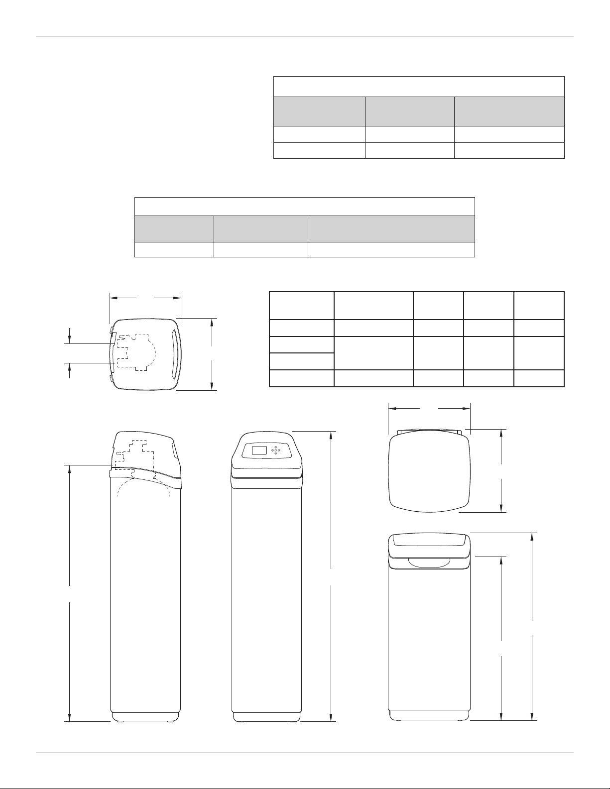
FRONT VIEWSIDE VIEW
IN - OUT
TOP VIEW
14"
14"
IN
OUT
A
16-1/4"
16"
36-9/16"
32"
BRINE TANK
B
C
Performance Claims & Dimensions
PERFORMANCE CLAIMS
est parameters include: pH = 7.5 ±0.5
T
flow rate = 7.5 gpm
dynamic pressure = 35 ±5 psig
Models IDP40CC & IDP50CC have not been tested or certified by NSF International or the Water Quality Association.
Contaminant
Barium 10 ±10% mg/L 2.0 mg/L
Radium 226/228 25 pCi/L 5 pCi/L
MODELS IDP40CC & IDP50CC PERFORMANCE CLAIM
Substance
Chloramines 3 mg/L >70% @ 10 gpm for 34,000 gal.*
Influent
Challenge Level
Reduction Requirement
* From manufacturer’s test data.
Influent
Challenge Level
Maximum Allowable
Product Water Level
IN
C
OUT
IN - OUT
14”
TOP VIEW
14”
Model
IDP30S 8” dia. x 40” 48-3/4” 42“ 3-3/8“
IDP40S
IDP40CC
IDP50CC 12” dia. x 54” 62-1/2” 55-3/4” 3-3/4“
Nominal Resin
Tank Size
10” dia. x 47” 56-3/4“ 50” 3-3/4“
DimensionADimensionBDimension
C
16”
16-1/4”
A
B
SIDE VIEW FRONT VIEW
4
BRINE TANK
36-9/16”
32”
FIG. 1
Before Starting Installation
WHERE TO INSTALL THE SOFTENER
= To soften all water in the home, install the water
softener close to the water supply inlet, upstream
of all other plumbing connections, except outside
water pipes. Outside faucets should remain on
hard water to conserve salt and softening capacity.
= Place the softener near a floor drain, or other
acceptable drain point (laundry tub, sump, standpipe, etc.) to carry away regeneration discharge
water.
= Connect the softener to the main water supply
pipe UPSTREAM OF the water heater. DO NOT
RUN HOT WATER THROUGH THE SOFTENER.
The temperature of water passing through the softener must be less than 120°F.
= Do not install the softener in a place where it could
freeze. Damage caused by freezing is not covered by the warranty.
= Put the softener in a place water damage is least
likely to occur if a leak develops. The manufacturer will not repair or pay for water damage.
= A 120V, 60 Hz electrical outlet, to plug the included
power supply into, is needed near the softener.
Be sure the electrical outlet and power supply are
in an inside location, to protect from wet weather.
= If installing in an outside location, you must take
the steps necessary to assure the softener, installation plumbing, wiring, etc., are as well protected
from the elements, contamination, vandalism, etc.,
as when installed indoors.
= Keep the softener out of direct sunlight. The sun's
heat may soften and distort plastic parts.
TOOLS, PIPE & FITTINGS,
OTHER MATERIALS YOU WILL NEED
= ALWAYS install a single bypass valve, or a 3-valve
bypass system. Bypass valves let you turn off water
to the softener for repairs if needed, but still have
water available to the house pipes.
= Plastic inlet and outlet fittings are included with the
softener, which allow water flow equivalent to 1 inch
nominal pipe. To maintain maximum valve flow, 1”
pipes to and from the softener fittings are recommend ed. Do not reduce the pipes to less than 3/4” size.
= Use copper, brass or PEX plastic pipe and fittings.
= Drain hose, 1/2” inside diameter minimum, is needed
for the valve drain.
= If a rigid valve drain is needed, to comply with
plumbing codes, you can buy the parts needed to
connect a 1/2” minimum copper tubing drain.
NOTE: The Commonwealth of Massachusetts plumbing
code 248-CMR shall be adhered to. A licensed plumber
shall be used for this installation.
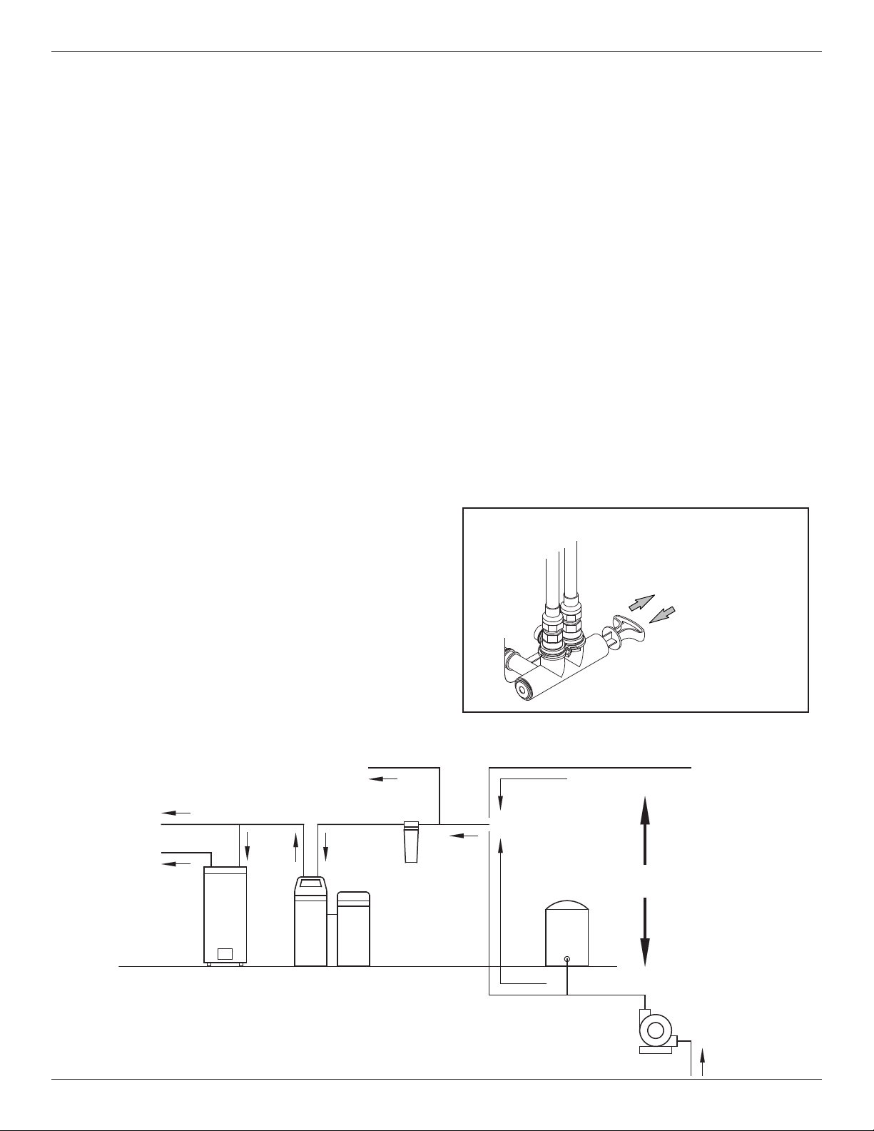
SINGLE BYPASS VALVE
Pull out for “Service”
(Soft water)
Push in for
“Bypass”
FIG. 2
Cold Water
to House
Hot Water
to House
THE PROPER ORDER TO INSTALL WATER TREATMENT EQUIPMENT
Untreated Water to
Outside Faucets
Water
Heater
Water
Softener
Optional
Sediment
Filter
Pressure
5
City Water Supply
Tank
Well Water Supply
OR
Well
Pump
FIG. 3
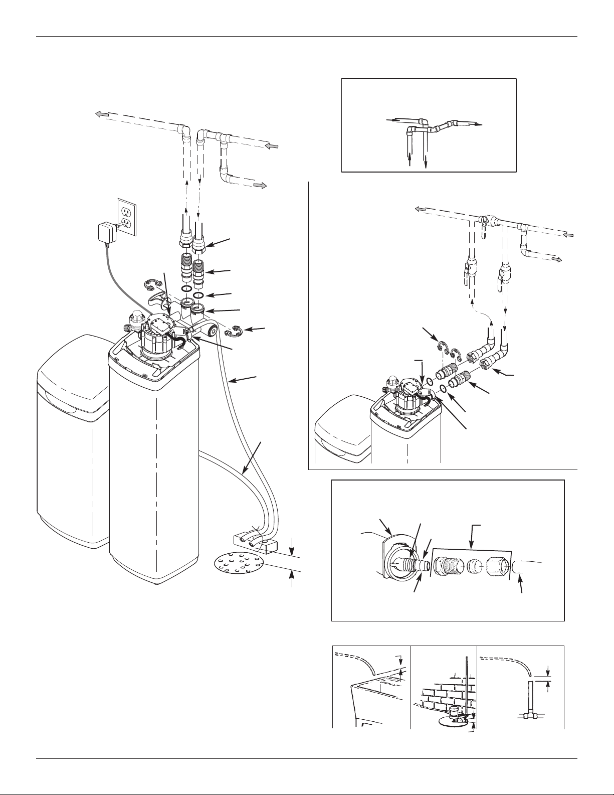
Typical Installation Illustrations
INSTALLATION USING SINGLE BYPASS VALVE
Soft Water
OUT
20V,
1
60 Hz
Outlet
M
A
OUTLET
IN
WAT
E
R
P
IP
E
Hard Water to
Outside Faucets
1” NPT
Female Adaptor (2)
not included
1” NPT Installation
Adaptor (2)*
O-Ring Seal (2)*
Bypass Valve
INLET
Brine Tank
Overflow
Hose**
Clip (2)*
Valve
Drain
Hose
Hard
Water IN
CROSS-OVER
Use if water supply flows from the left.
Include single or 3-valve bypass.
SOFT
ATER
W
ROM SOFTENER
F
UTLET
O
O SOFTENER
T
NLET
I
INSTALLATION USING 3-VALVE BYPASS
M
A
For soft water SERVICE:
-Open the inlet and outlet
valves
For hard water BYPASS:
-Close the inlet and outlet
valves
-Open the bypass valve
Clip (2)*
OUTLET
UTLET
O
Valve
BYPASS
Valve
O-Ring Seal (2)*
INLET
ARD
H
WATER
IN
WAT
ER
PIPE
NLET
I
Valve
1” NPT
Female Adaptor
(2) not included
1” NPT Installation
Adaptor (2)*
FLOOR
Secure Valve Drain Hose
in place over Floor Drain
DRAIN
1-1/2”
Air Gap
*Included with softener - Pipe and fittings supplied by installer.
**Do not connect the water softener valve drain hose to the brine
tank overflow hose.
CONNECTING A RIGID VALVE DRAIN TUBE
Clip
Cut barbs from drain fitting (pull
clip to remove fitting from valve)
1/4 NPT Threads
Barbs
Compression Fitting.
1/4 NPT x 1/2” O.D.
Tube (not included)
1/2” Outside Dia. Copper
Tube (not included)
To standpipe, sump, laundry tub or other suitable drain.
1-1/2”
Air Gap
LAUNDRY
TUB
SUMP
1-1/2” Air Gap
6
1-1/2”
Air Gap
STAND
PIPE
FIG. 4

Installation
1. TURN OFF WATER SUPPLY
a. Close the main water supply valve near the well
pump or water meter.
b. Shut off the electric or fuel supply to the water
heater.
c. Open high and low faucets to drain all water from
the house pipes.
2. INSTALL BYPASS VALVE AND/OR
PLASTIC ADAPTORS:
a. If installing a single bypass valve, push the bypass
valve, with lubricated o-ring seals in place, into the
valve inlet and outlet ports (See Figures 4 & 5).
- OR -
b. If installing a 3-valve bypass system, slide plastic
installation adaptors, with lubricated o-ring seals in
place, into the valve inlet and outlet ports (See
Figure 4 & 5).
c. Be sure the turbine support is in place in the valve
outlet, as shown in Figure 6.
d. Snap the two large plastic clips in place on the inlet
and outlet ports, from the top, down (See Figure
7). Be sure they snap into place. Pull on the
bypass valve or plastic adaptors, to make sure
they are held securely in place.
Clips
INLET
Lubricated
O-Rings
Turbine
Clip
OUTLET
Turbine
Turbine
Support
Plastic
nstallation Adaptors
I
(install in softener valve
or bypass valve)
Support
Single
Bypass Valve
Valve
Outlet
Clip
FIG. 5
3. COMPLETE PLUMBING TO AND FROM
THE SOFTENER
Using the “Typical Installation Illustration” on page 6
as a guide, observe all of the following cautions while
you connect inlet and outlet plumbing:
= Be sure incoming, hard water is directed to the
valve INLET port.
= Be sure to install bypass valve(s).
= If making a soldered copper installation, do all
sweat soldering before connecting pipes to the
softener fittings. Torch heat will damage plastic
parts.
= Use pipe joint compound on all external pipe
threads.
= When turning threaded pipe fittings onto plastic fit-
tings, use care not to cross-thread.
= Support inlet and outlet plumbing in some manner
(use pipe hangers) to keep the weight off of the
valve fittings.
O-ring
Cross section of
valve inlet or outlet
Snap clips into place between
INLET
Clip
larger diameter rings
Turn the bypass
valve downward if
connecting to floor
level plumbing
OUTLET
FIG. 6
Bypass valve or
plastic adaptor
FIG. 7
FIG. 8
7
round
G
Clamp
Installation
Nut
Brine
ank
T
Brinewell
over
C
rine
B
Tubing
Inlet / Outlet
Pipes
FIG. 9
4. COLD WATER PIPE GROUNDING
The house cold water pipe (metal only) is often used
as a ground for the house electrical system. The 3valve bypass type of installation, shown in Figure 4,
will maintain ground continuity. If you use the plastic
bypass, continuity is broken. To restore the ground,
do either step 4a or 4b following.
a. Use the ground clamp kit (not included) to make a
jumper across the inlet and outlet pipes (See Figure
9).
b. Install a #4 copper wire across the removed section of main water pipe, securely clamping at both
ends – parts not included.
5. INSTALL VALVE DRAIN HOSE
a. Take a length of 1/2” inside diameter hose and
attach to the valve drain fitting, securing it with a
hose clamp (See Figure 4 on page 6).
b. Locate the other end of the hose at a suitable drain
point (floor drain, sump, laundry tub, etc.). Check
and comply with local codes. Refer to Figure 4 if
codes require a rigid pipe drain run.
IMPORTANT: Use high quality, thick wall hose that
will not easily kink or collapse. The
softener will not backwash properly if
water cannot exit this hose during
recharges.
c. Tie or wire the hose in place at the drain point.
Water pressure will cause it to whip during the
backwash portion of the recharge cycle. Also provide an air gap of at least 1-1/2” between the end
of the hose and the drain point. An air gap prevents possible siphoning of sewer water, into the
softener, if the sewer should back up.
d. If raising the drain hose overhead is required to get
to the drain point, do not raise higher than 8 feet
above the floor. Elevating the hose may cause a
back pressure that could reduce backwash flow
and proper resin bed cleaning.
Elbow
Grommet
Screw
Brinewell
Brine
Valve
Slots
FIG. 10
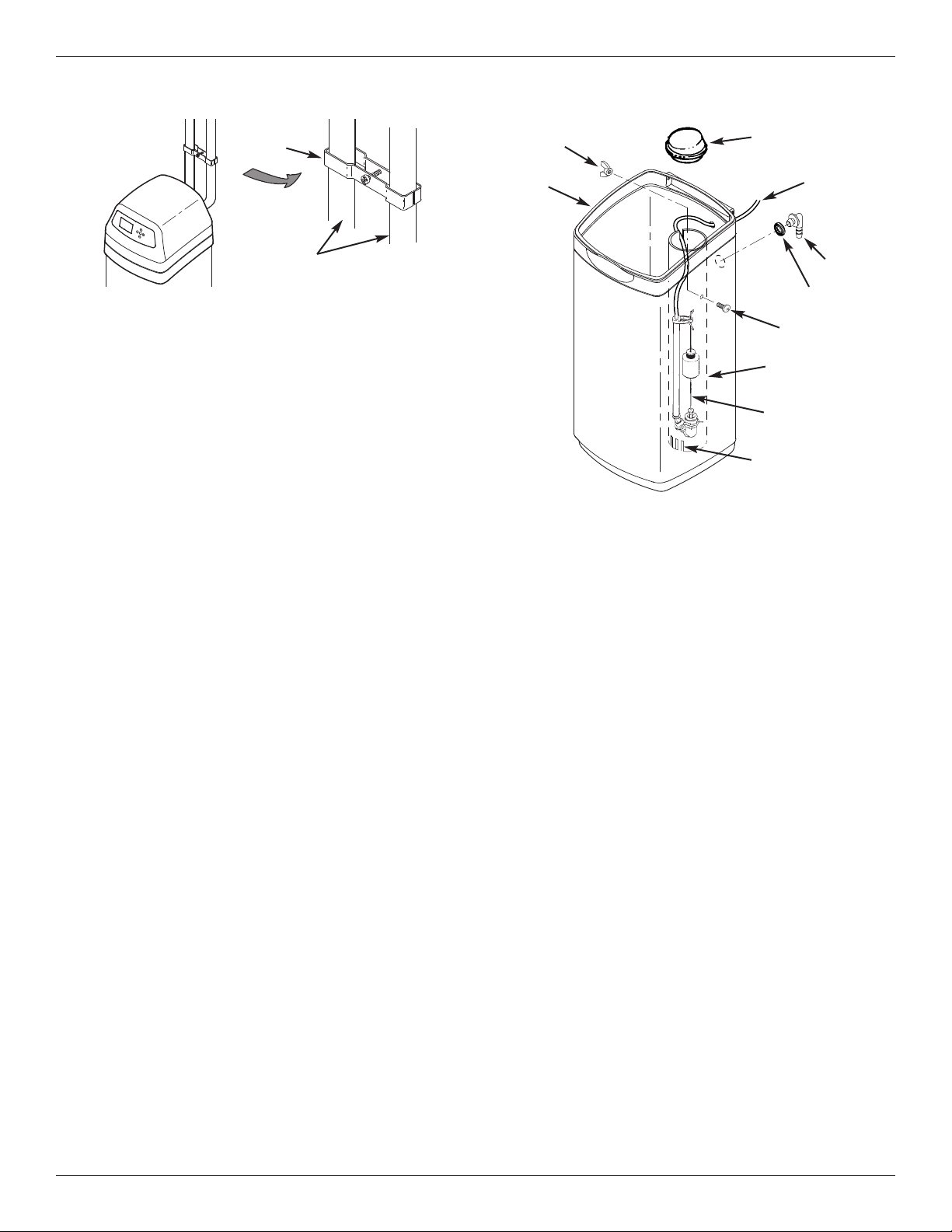
6. BRINE TANK ASSEMBLY
Complete the following steps for Models IDP30S,
IDP40S and IDP40CC. For Model IDP50CC, shipped
with an assembled brine tank, proceed to Step 7.
a. Place the brinewell into position in the brine tank,
with the slots at the bottom, as shown in Figure 10.
Align the mounting hole in the brinewell with the corresponding hole in the tank wall. Then use the screw and
nut from the parts bag to fasten the brinewell in place.
b. Lower the brine valve into the brinewell. Push the
tubing into the brinewell top slot (Fig. 10) and route it
out of the brine tank through the smaller hole in the rear
wall of the brine tank.
c. Install the brinewell cover.
7. INSTALL BRINE TANK OVERFLOW HOSE
This drain is for safety only. If the brine tank should
over-fill with water, the excess is carried to the drain.
a. Take the rubber grommet and hose adaptor elbow
from the parts bag. Push grommet into the corresponding hole in the back wall of the brine tank.
Then insert the larger diameter end of the elbow
through the grommet.
b. Attach a length of 1/2” inside diameter hose to the
drain elbow, installed in the previous step. Use a
hose clamp to hold it in place.
c. Locate the other end of the hose at the drain point.
Do not elevate this hose higher than the elbow on
the brine tank. Do not tee this hose to the valve
drain hose.
8

Installation
Ferrule
Nut
Brine Tubing
Brine Tank
Overflow Hose
Valve
Drain Hose
Floor
Drain
1-1/2”
Air Gap
FIG. 11
8. CONNECT BRINE TUBING
a. Route the brine tube out of the brine tank through
the smaller hole in the tank back wall.
b. Connect the brine tube to the nozzle/venturi
assembly using the ferrule nut provided (See
Figure 11).
g. Make sure the softener’s bypass valve is in the
bypass position.
h. Plug in the power supply.
i. Program the electronic controller: Follow the
steps on Page 11 to program the electronic controller with basic operating information, such as time
and water hardness. After completing these steps,
continue with “j. Start a recharge”, below.
j. Start a recharge: From the rolling status screens,
press the SELECT (¡) button to display the Main
menu. Make sure Recharge is highlighted, then
press SELECT (¡). Press DOWN (6) to scroll to
Recharge now, then press SELECT (¡) twice.
You should hear the valve motor run as the softener
begins recharging.
k. Once the unit is in backwash, place bypass
valve(s) into the service position, as follows:
(1) SINGLE BYPASS VALVE: Slowly move the
valve stem toward service position, pausing several times to allow the unit to pressurize slowly.
(2) 3-VALVE BYPASS: Fully close the bypass
valve and open the outlet valve. Slowly open
the inlet valve, pausing several times to allow the
unit to pressurize slowly.
l. Let the softener complete the backwash and fast
rinse cycles (takes 10-12 minutes). When the
recharge cycle ends, the softener valve returns to
the service position.
9. PRESSURE TESTING FOR LEAKS,
PROGRAMMING THE CONTROLLER &
RINSING THE MEDIA
To prevent excessive air pressure in the water
softener and plumbing system, do the following
steps EXACTLY in order:
a. Fully open two or more softened cold water
faucets nearby the water softener.
b. Place the bypass valve(s) in bypass position (See
Figures 2 & 4).
c. Fully open the main water supply valve. Watch
until the flow from the opened faucets becomes
steady, with no spurting or air bubbles.
d. After about three minutes, open a hot water faucet
for one minute, or until all air is expelled.
e. Close all faucets and check your plumbing work for
leaks.
f. Make sure the softener’s valve drain hose is
hooked up and the open end directed to a floor
drain, laundry tub or other suitable type of drain.
10. ADD WATER AND SALT TO THE
BRINE TANK
a. Using a pail or garden hose, add about 3 gallons of
water into the brine tank. DO NOT pour into the
brinewell.
b. Add salt to the brine tank. It is recommended to fill
the brine tank no more than 1/2 full. Level the salt
when finished adding. You can use most water
softener salts, but it must be clean.
Recommended nugget, pellet or coarse solar salts
have less than 1% impurities.
NOTE: See page 26 for additional information on salt.
9

Installation & Sanitizing
11. SANITIZING THE WATER SOFTENER
Care is taken at the factory to keep your water softener clean and sanitary. However, during shipping, storage, installing and operating, bacteria could get into
the unit. For this reason, sanitizing as follows is suggested* when installing.
a. Remove the brinewell cover and pour about 1-1/2
oz. (2 to 3 tablespoons) of common household
bleach into the softener’s brinewell. Replace the
brinewell cover.
b. Make sure the bypass valve is in the service posi-
tion.
c. Start a recharge: From the rolling status screens,
press the SELECT (¡) button to display the Main
menu. Make sure Recharge is highlighted, then
press SELECT (¡). Press DOWN (6) to scroll to
Recharge now, then press SELECT (¡) twice.
You should hear the valve motor run as the softener begins recharging. This recharge draws the
sanitizing bleach into and through the softener.
Any air remaining in the unit is purged to the drain.
d. After the recharge has completed, fully open a cold
water faucet, downstream from the softener, and
allow 50 gallons of water to pass through the system. This should take at least 20 minutes. Close
the faucet.
12. RESTART THE WATER HEATER
Turn on the electric or fuel supply to the water heater,
and light the pilot, if applies.
NOTE: The water heater is filled with hard water and,
as hot water is used, it refills with softened water. In
a few days, the hot water will be fully conditioned. To
have fully conditioned hot water immediately, wait
until the recharge (Step 11) is complete, then drain
the water heater until water runs cold.
*NOTE: Sanitizing is recommended by the Water Quality
Association for disinfecting. On some water supplies, they suggest periodic sanitizing.
10
Setup Procedure
English
Metric
System units
12:34 PM
Current time
Salt level
4
0.0 PPM
Iron level
Run system
Redo setup
Setup complete!
English
Español
Français
Language
25 Grains
Hardness
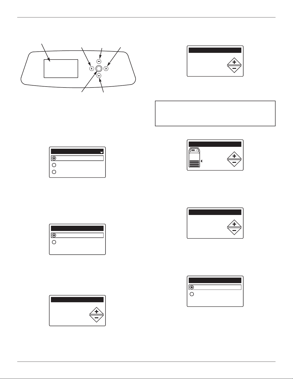
Display
LEFT
Button
SELECT
Button
UP
Button
DOWN
Button
RIGHT
Button
FIG. 12
SETUP PROCEDURE
When the water softener is plugged in for the first time,
a beep sounds and the display briefly shows model
information. Next, a series of “wizard” screens prompts
you to enter basic operating information:
FIG. 13
1. LANGUAGE If the desired language already has a
black dot next to it (See Figure 13), go to Step 2.
Otherwise, press the softener’s DOWN (6) or UP
(5) buttons to scroll to the desired language, then
press the SELECT (¡) button to choose it.
2. Press the SELECT (¡) button to advance to the next
“wizard” screen.
6. Press the SELECT (¡) button.
FIG. 16
7. HARDNESS Press the UP (5) or DOWN (6) but-
tons to set the value of your water’s hardness (See
Figure 16).
NOTE: Do not increase the hardness setting to
compensate for iron in your water. The
electronic control compensates automatically
after you set the iron level in Step 11, below.
8. Press the SELECT (¡) button.
FIG. 17
9. SALT LEVEL Press the UP (5) or DOWN (6) but-
tons to set the salt level (See Figure 17). It should
match the lowest number visible on the brinewell
above the salt.
10. Press the SELECT (¡) button.
3. SYSTEM UNITS If the desired system already has a
black dot next to it (See Figure 14), go to Step 4.
Otherwise, press the DOWN (6) or UP (5) buttons
to scroll to the desired system, then press the
SELECT (¡) button to choose it.
4. Press the SELECT (¡) button.
5. CURRENT TIME Press the DOWN (6) or UP (5)
buttons to set the current time (See Figure 15). Hold
the button down to rapidly advance. Be sure that AM
or PM is correct. If the system units were set to metric in Step 3, the clock will be in 24-hour format.
FIG. 18
11. IRON LEVEL Press the UP (5) or DOWN (6) but-
FIG. 14
tons to set the value for iron in your water (See
Figure 18)
12. Press the SELECT (¡) button. The screen will
show “Setup complete!” (See Figure 19).
FIG. 19
13. If, at this point, you want to go back and make
changes, press the DOWN (6) button to scroll to
FIG. 15
11
Redo setup, then press the SELECT (¡) button
twice to repeat the “wizard” screens.
14. If no changes are desired, make sure Run system
has a black dot next to it (See Figure 19) and press
the SELECT (¡) button. The unit begins normal
operation, described on the next page.
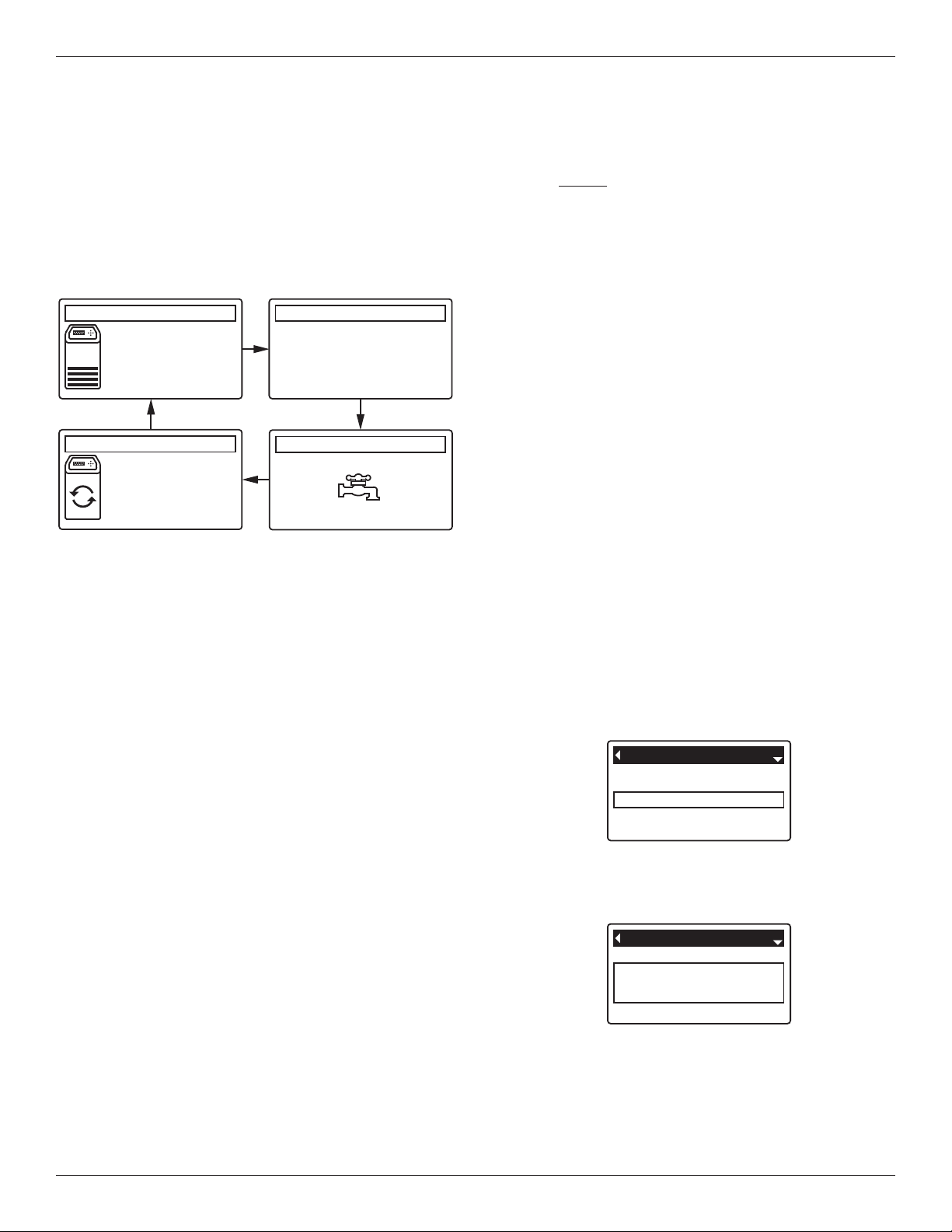
0.0 GPM
Water flow
2:34 PM
Salt status (NaCl)
2:34 PM
Water use (gallons)
2:34 PM
Out of salt in
119 days
Recharge status
2:34 PM
Set for automatic
recharge
Today: 121
Daily average: 175
Remaining: 736
Efficiency mode
Max. days between rech...
Auxiliary control
Special features
Effieciency mode
Auxiliary control
Special features
Max. days between
recharges
Programming the Water Softener
NORMAL OPERATION
SOFTENER STATUS SCREENS
uring normal operation, the water softener’s display
D
shows up to four status screens. Page 18 explains how
ndividual screens can be turned on or off. Each is
i
shown for six seconds, in a rolling sequence (See
Figure 20).
*
*Water remaining before the next recharge.
Pressing the softener’s RIGHT (4) button manually
advances to the next screen in the sequence. Pressing
the LEFT (3) button manually returns to the previous
status screen. If no buttons are pressed for 30 seconds, the automatic rolling sequence resumes.
FIG. 20
OTHER MESSAGES, ALERTS & REMINDERS
The softener status screens described in the previous
section will not be displayed in a rolling sequence when
one of the following items is displayed:
=Recharge status (Displayed during recharges,
showing valve position and time remaining)
=Add salt or Out of salt (See Page 26)
=Current time setting screen instead of status
screens indicates time has been lost, perhaps after
a long power loss. Set the time (See Page 16).
=Service reminder (See Page 24)
=Error detected (Contact your dealer for service)
FLASHING DISPLAY
The softener’s display will flash on and off when one or
more of the following conditions occurs:
=Salt needs to be added
=Time needs to be set (Time has been lost)
=Service is overdue (Service reminder)
=Error condition
The flashing will stop after any key is pressed.
However, it will start again at Midnight if the underlying
condition (e.g. low salt level) has not been addressed.
LONG DISPLAY SCREEN MESSAGES
Most messages in the softener’s display screens are
short enough to be shown as a single line. Longer
messages will be truncated (See Figure 21 for an
example) until you highlight them.
FIG. 21
One second after being highlighted, the viewing box
expands (See Figure 22) to show the entire message.
After three seconds the view resets (Figure 21).
FIG. 22
12
 Loading...