

Eclipse BrightFire 200 Burners
BRT Size G, M, and B
Operating Instructions Edition 09.15
Version 1
Copyright
Copyright 2013 by Eclipse, inc. All rights reserved
worldwide. This publication is protected by federal
regulation and shall not be copied, distributed,
transmitted, transcribed or translated into any human or
computer language, in any form or by any means, to any
third parties, without the express written consent of
Eclipse, inc.
Disclaimer Notice
In accordance with the manufacturer’s policy of continual
product improvement, the product presented in this
brochure is subject to change without notice or obligation.
The material in this manual is believed adequate for the
intended use of the product. If the product is used for
purposes other than those specified herein, confirmation
of validity and suitability must be obtained. Eclipse
warrants that the product itself does not infringe upon any
United States patents. No further warranty is expressed or
implied.
Liability & Warranty
We have made every effort to make this manual as
accurate and complete as possible. Should you find errors
or omissions, please bring them to our attention so that we
may correct them. In this way we hope to improve our
product documentation for the benefit of our customers.
Please send your corrections and comments to our
Technical Documentation Specialist.
It must be understood that Eclipse’s liability for its product,
whether due to breach of warranty, negligence, strict
liability, or otherwise is limited to the furnishing of
replacement parts and Eclipse will not be liable for any
other injury, loss, damage or expenses, whether direct or
consequential, including but not limited to loss of use,
income, or damage to material arising in connection with
the sale, installation, use of, inability to use, or the repair
or replacement of Eclipse’s products.
Any operation expressly prohibited in this manual, any
adjustment, or assembly procedures not recommended or
authorized in these instructions shall void the warranty.
Document Conventions
There are several special symbols in this document. You
must know their meaning and importance.
The explanation of these symbols follows below. Please
read it thoroughly.
How To Get Help
If you need help, contact your local Eclipse
representative. You can also contact Eclipse at:
1665 Elmwood Rd.
Rockford, Illinois 61103 U.S.A.
Phone: 815-877-3031
Fax: 815-877-3336
http://www.eclipsenet.com
Please have the information on the product label available
when contacting the factory so we may better serve you.
www.eclipsenet.com
Product Name
Item #
S/N
DD MMM YYYY
WARNING
CAUTION
NOTICE
NOTE
This is the safety alert symbol. It is used to alert you to potential personal
injurt hazards. Obey all safety messages that follow this symbol to avoid
possible injury or death.
Indicates a hazardous situation which, if not avoided, will result in death
or serious injury.
Indicates a hazardous situation which, if not avoided, could result in
death or serious injury.
Indicates a hazardous situation which, if not avoided, could result in
minor or moderate injury.
Is used to address practices not related to personal injury.
Indicates an important part of text. Read thoroughly.
2

Table of Contents
Introduction ..................................................................................................................................... 4
Product Description .............................................................................................................. 4
Benefits ................................................................................................................................ 4
Audience .............................................................................................................................. 4
BrightFire Documents........................................................................................................... 4
Purpose ................................................................................................................................ 4
Safety................................................................................................................................................ 5
Capabilities........................................................................................................................... 5
Operator Training ................................................................................................................. 5
Replacement Parts...............................................................................................................5
Installation .......................................................................................................................................6
Handling & Storage ..............................................................................................................6
Approval of Components...................................................................................................... 6
BrightFire 200 Adjustable Burners ....................................................................................... 7
Gimbal Mounting Bracket Installation................................................................................... 7
Pre-Start Considerations ...................................................................................................... 7
BrightFire 200 Installation and Start-Up During Initial Heat-Up Furnace.............................. 8
BrightFire 200 Installation to Convert Existing Burners........................................................ 9
Adjustment....................................................................................................................................... 11
BrightFire 200 Flame Adjustments ....................................................................................... 11
Converting BrightFire 200 from Gas to Oil Firing ................................................................. 12
Maintenance..................................................................................................................................... 13
Periodic Checklist................................................................................................................. 13
Monthly Checklist ................................................................................................................. 13
Yearly Checklist.................................................................................................................... 13
Instructions for Cleaning.......................................................................................................13
Appendix .......................................................................................................................................... i
3BrightFire 200, V1, Operating Instructions, Edition 09.15
Introduction
1
Product Description
The BrightFire® 200 burner is an adjustable, low NOX, airfuel burner for installation in regenerative type glass
furnaces. It can be installed in either end-fired or crossfired furnaces, as well as in under port or side-of-port
configurations. It is designed to work with the Eclipse
Gimbal Mounting Bracket to provide excellent adjustability of the flame position within the furnace. Additionally
the socket plate provides for a positive seal against the
burner block ensuring air is not infiltrated into the furnace.
Cooling air is provided through the inner gas tube during
off-firing cycles to prevent nozzle burnout.
These burners are of a welded, stainless steel body
construction, produce a highly adjustable flame, and
provide superior heat transfer to the glass melt. Multiple
burners may be used in each port. Port design must be
compatible with the burner.
Benefits
• Additional adjustments for increased flame control
and burner flexibility.
• Lower NOX emissions.
• Compatible with current mounting bracket for easy
installation.
• Compatible with current BrightFire™ gas and cooling air connections for easy conversion.
• Nozzle combinations allow firing to be tailored to furnace requirements.
• Durable construction.
• Low Maintenance.
• Improved glass quality.
• Reduced fuel usage due to improved heat transfer
into the glass.
Audience
This manual has been written for people who are already
familiar with all aspects of a glass burner and its add-on
components, also referred to as “the burner system”.
These aspects are:
• Installation
• Use
• Maintenance
The audience is expected to have previous experience
with this type of equipment.
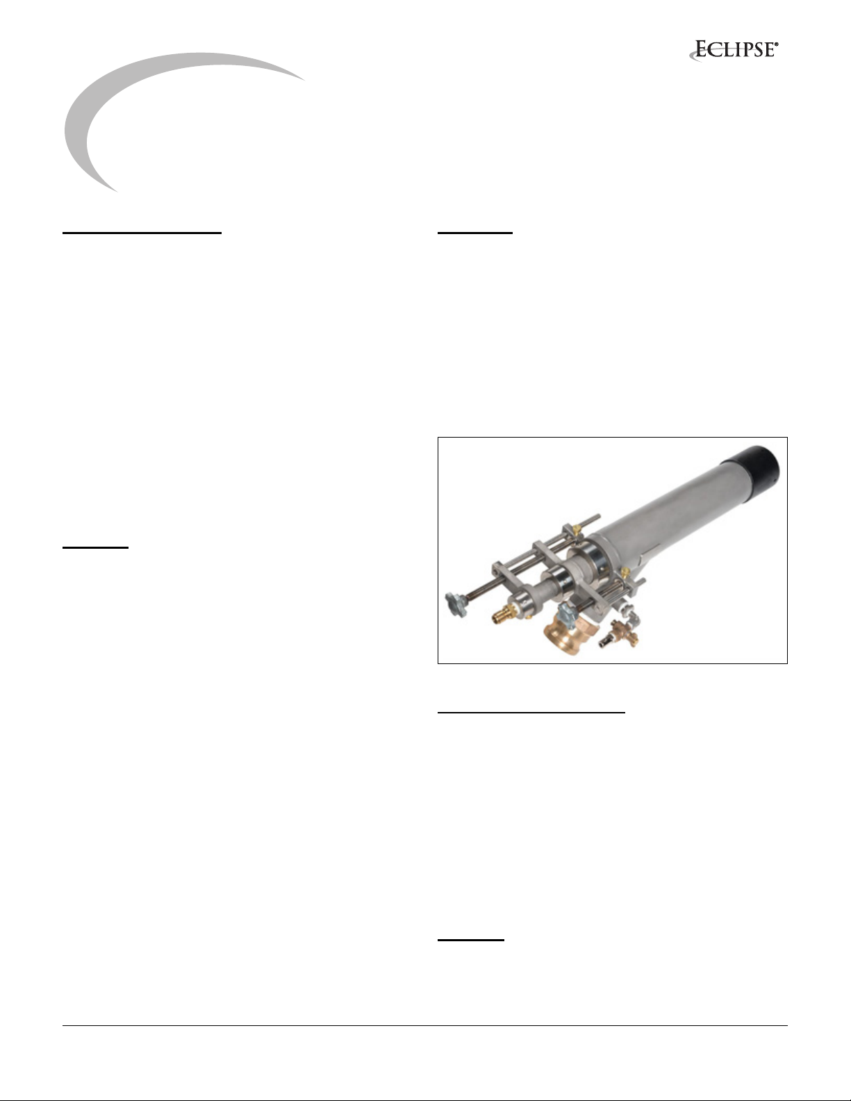
Figure 1.1. BrightFire
®
200 Burner
BrightFire® Documents
Information Guide
• This document
Datasheet, Series 1112-1 through 1112-3
• Available for individual BrightFire 200 models.
Spare Parts List
• Recommended replacement part information
Related Documents
• EFE 825 (Combustion Engineering Guide)
• Gimbal Mounting Bracket Information Guide 1113
Purpose
The purpose of this manual is to ensure the installation
and adjustment of a safe, effective and trouble-free
combustion system.
4BrightFire 200, V1, Operating Instructions, Edition 09.15
Safety
2
Important notices, which help provide safe burner
operation, will be found in this section. To avoid personal
injury and damage to the property or facility, the following
warnings must be observed. All involved personnel
should read this entire manual carefully before attempting
to start or operate this system. If any part of the
information in this manual is not understood, contact
Eclipse before continuing.
WARNING
■ DO NOT disassemble any component WITHOUT
first reading the manufacturer’s instructions.
Several components contain parts under
compression or pressure and could injure
personnel if not disassembled properly.
■ Control panels contain voltages which can
severely injure personnel. These panels are
normally double fed from the emergency supply.
NO engineer/maintenance technician who is not
fully conversant with the equipment should be
allowed access to the panel internals.
■ The burners, described herein, are designed to
mix fuel with air and burn the resulting mixture. All
fuel burning devices are capable of producing fires
and explosions if improperly applied, installed,
adjusted, controlled or maintained.
■ Do not bypass any safety feature; fire or explosion
could result.
■ Never try to light a burner if it shows signs of
damage or malfunction.
■ The burner and duct sections are likely to have
HOT surfaces. Always wear the appropriate
protective equipment when approaching the
burner.
NOTICE
■ This manual provides information regarding the
use of these burners for their specific design
purpose. Do not deviate from any instructions or
application limits described herein without written
approval from Eclipse.
■ Control circuits MUST not be altered at any time
unless Eclipse has been consulted and has
approved the modifications.
■ No naked lights are to be used in the area of gas
pipeline components.
■ Any gas leaks should always be isolated and
rectified immediately. Any piece of pipeline
equipment and its surrounding area should be
properly vented and/or purged as appropriate after
isolation and before the start of any maintenance.
■ Extreme care should be taken when working on
burner equipment installed under the furnace port.
■ Eclipse recommends installing a safety guard
around moving parts.
■ Eclipse recommends considering any area with
moving mechanical parts a restricted area.
Capabilities
Only qualified personnel, with sufficient mechanical
aptitude and experience with combustion equipment,
should adjust, maintain or troubleshoot any mechanical or
electrical part of this system.
Operator Training
The best safety precaution is an alert and trained
operator. Train new operators thoroughly and have them
demonstrate an adequate understanding of the
equipment and its operation. A regular retraining schedule
should be administered to ensure operators maintain a
high degree of proficiency.
Replacement Parts
Order replacement parts from Eclipse only. All Eclipse
approved valves or switches should carry UL, FM, CSA,
CGA and/or CE approval where applicable.
5BrightFire 200, V1, Operating Instructions, Edition 09.15

Installation
3
In this section you will find information and instructions
needed to install the burner and the system components.
Handling & Storage
Handling
• Make sure the area is clean.
• Protect all components from weather, damage, dirt
and moisture.
• Protect the components from excessive
temperatures and humidity.
• Take care not to drop or damage components.
Storage
• Make sure the components are clean and free of
damage.
• Store the components in a cool, clean, dry room.
• After you have made sure everything is present and
in good condition, keep the components in their
original packaging as long as possible
Approval of Components
Limit Controls & Safety Equipment
All limit controls and safety equipment must comply with
all applicable local codes and/or standards and must be
listed for combustion safety by an independent testing
agency. Typical application examples include:
• American: NFPA 86 with listing marks from UL, FM,
CSA
• European: EN 746-2 with CE mark from TuV,
Gastec, Advantica
Electrical Wiring
All the electrical wiring must comply with all applicable
local codes and/or standards such as:
• NFPA Standard 70
• IEC60364
• CSA C22
• BS7671
Gas Piping
All the gas piping must comply with all applicable local
codes and/or standards such as:
• NFPA Standard 54
• ANSI Z223
• EN 746-2
Where to Get the Standards:
The NFPA Standards are available from:
National Fire Protection Agency
Batterymarch Park
Quincy, MA 02269
www.nfpa.org
The ANSI Standards are available from:
American National Standard Institute
1430 Broadway
New York, NY 10018
www.ansi.org
The UL Standards are available from:
333 Pfingsten Road
Northbrook, IL 60062
www.ul.com
The FM Standards are available from:
1151 Boston-Providence Turnpike
PO Box 9102
Norwood, MA 02062
www.fmglobal.com/approvals
Information on the EN standards and where to get them is
available from:
Comité Européen de Normalisation
Stassartstraat 36
B-1050 Brussels
Phone: +32-25196811
Fax: +32-25196819
www.cen.eu
Comité Européen de Normalisation Electronique
Stassartstraat 36
B-1050 Brussels
Phone: +32-25196871
Fax: +32-25196919
www.cenelec.org
6BrightFire 200, V1, Operating Instructions, Edition 09.15

BrightFire® 200 Adjustable Burners
The BrightFire® 200 is available in three body sizes, G, M
and B, with diameters of 73.0 mm (2.88”), 88.9 mm (3.50”)
and 101.6 mm (4.00”), respectively. All three sizes consist
of an outer tube with a separate inner tube to provide two
separate gas jets.
Each burner includes two adjustments (see Figure 2.1).
The first adjustment (the longer adjusting screw) changes
the annulus area between the inner and outer nozzle tips,
providing changes to the annular gas jet velocity at the
burner tip to control flame length. The second adjustment
(the shorter adjusting screw) is incorporated into the
middle tube and is used to open and close an orifice within
the annular gas jet which changes the gas flow
distribution between the inner and outer gas jets. This
unique inner flow adjustment allows the heat release from
the flame to be adjusted independent of the flame length.
See BrightFire®200 Flame Adjustment section for more
information.
4. Install the alignment tube in the bracket, ensuring that
the alignment tube pin is in contact with the gimbal ring
of the bracket to simulate burner position and allow for
proper working distance from the socket plate to the
face of the burner nozzle.
5. With the alignment tube in place, push the bracket
assembly forward to hold the socket plate in place.
6. Sight down the alignment tube and adjust the bracket
to match the centerline of the tube to the centerline of
the burner block opening.
7. Tighten the mounting bolts of the bracket and secure
the socket plate to the block using the jack bolts on the
bracket. Slight adjustments may be required after heatup due to thermal expansion.
8. Tighten the bracket mounting bolts after final
adjustment and remove the alignment tube.
9. Seal the block opening with refractory fiber blanket for
heat up.
Nozzles can be supplied with the burners for a variety of
inputs (2 to 10 MM Btu/h gross (528 to 2638 kW net) for
G-size; 5 to 17 MM Btu/h gross (1319 to 4484 kW net) for
M-size; and 10 to 31 MM Btu/h gross (2638 to 8177 kW
net) for B-size). Two types of nozzles are available to
provide flame length, heat release, and emissions tailored
to specific furnace requirements.
The two available nozzle types are a straight body nozzle
and a profiled nozzle. The profiled nozzle provides greater
heat and flame control when compared to the similarly
sized straight body nozzle. However, the same size
straight body nozzle will provide a reduction in NO
emissions compared to the profiled nozzle.
Oil lances are also available in a variety of inputs from 2
to 28 MM Btu/h (528 to 7388 kW). Oil lances are easy to
install in place of the inner gas tube for a flexible back-up
option in the event of natural gas interruptions.
The burner length and diameter must be determined from
the furnace and port information.
Gimbal Mounting Bracket Installation
NOTE: For additional info on the Gimbal Mounting
Bracket, refer to Info Guide 1113.
1. Set all bracket adjustments to zero using the scales and
pointers.
2. Place the socket plate in the recess of the burner block
3. Loosely attach bracket to furnace steel and roughly
align with the centerline of the burner block opening.
Pre-Start Considerations
• Ensure all components are on site: burners,
brackets, socket plates, etc.
• All threaded components should have anti-seize
applied.
• Ensure burner tool kit matches burner size. Kits
include: ratchet, spanner wrenches, burner
alignment tube, and anti-seize.
• Confirm cooling air has local flow control and
X
pressure gauge (0-15 PSI (0 – 1 bar)) for each
burner.
• Confirm gas has local flow control and measurement
provisions.
• Test the fit of the gas and cooling air flex hoses.
• Mount the burner and ensure supply lines can easily
be attached.
• Confirm cooling air and natural gas check valves are
fitted and within 2.5 m (8 ft) of the burner.
• Confirm that the check valves have been properly
installed in the gas and cooling air lines.
• Preset the manual gas flow control valve for each
burner to 50% open to allow for adjustment in both
directions and to establish a rough gas flow balance
across the burners.
7BrightFire 200, V1, Operating Instructions, Edition 09.15

• Ensure local gas and cooling air valves are closed.
The main gas and cooling air supplies should
remain closed until the main burners are to be
brought on line.
• Confirm that the burner blocks are plugged prior to,
and during, heat-up.
• Confirm that the external cooling wind ducts are in
place and directed at the socket plates.
BrightFire® 200 Installation and Start-Up
During Initial Heat-up of Furnace
NOTE: Once the furnace temperature is above the auto-
ignition temperature of the gas, the main burners can be
gradually brought on line.
CAUTION
■ To ensure ignition of gas, allow the furnace to
reach a minimum of 1400º F (760º C) before
starting gas flow to the burners.
NOTE: as the gas flow to the main burners is increased,
the heat-up burner input is decreased to maintain the
heat-up schedule until the heat-up burner can be
removed.
Figure 3.2. Typical Installation (Side of Port)
1. Ensure everyone involved is aware of, and ready for,
the main burner lite-off.
Support Channel
Supplied by Customer
Figure 3.1. Typical Installation (Under port)
2. Ensure there is sufficient air flow for combustion.
3. Set the main gas flow control to manual and open to 1015%.
4. Establish gas and cooling air supply up to the local shut
off valves.
5. Prior to installing the burner in the bracket, set the area
adjustment (refer to figure 2.1 for burner adjustment
identification) so that the tip of the inner nozzle is about
even with the beginning of the taper of the outer nozzle
(see figure 1.3).
6. Set the flow adjustment to position 6 (refer to figure
2.3).
7. Attach the cooling air and gas hoses to the burner prior
to placing the burner in the bracket.
8BrightFire 200, V1, Operating Instructions, Edition 09.15

Start of Outer Nozzle Taper
Figure 3.3. Inner nozzle initial position for installation
8. Place one burner onto bracket on “off side” and push
forward until burner is tight against the socket plate.
9. Secure the burner in place by tightening the t-bolt or
split ring clamp, depending on which bracket style has
been supplied.
10. Ensure sufficient combustion air flow is present in all
ports.
11. Open the local cooling air valve and set the pressure
to 3 – 4 psi (207 – 276 mbar).
NOTE: To prevent damage to the burners in the event the
cooling air is lost for more than 20 minutes, the burner
should be removed and the block openings plugged with
refractory fiber.
12. After reversal, open the local gas valve at the installed
burner.
13. Visually confirm ignition and adjust the main gas flow
control to achieve the desired gas flow, ensuring the
flow is above the minimum input rating of the burner.
19. With all of the main burners in operation, a preliminary
gas flow balance may now be achieved and will vary
based on furnace design and/or the desired input or
temperature profile of the furnace. This should be done
with the gas control in manual.
The side of port firing arrangement incorporates two
burners per port. Both burners of any given port should
have equal gas flow and be adjusted in pairs when
balancing gas flow.
On a typical under port fired furnace, either side port or
end port, balancing the burners is usually a visual task
and can be checked with either gas inlet pressure or
differential pressure at an orifice plate.
In most conditions final burner balancing will not take
place until after the furnace is full and the regenerators
have heated to normal operating temperatures, thus
combustion air velocity at the port is at normal levels.
Air/fuel ratio to this point has been primarily controlled
visually with aid from instrumentation. Once the thermal
expansion of the furnace is complete, any cracks or gaps
will be sealed. Port flue gas readings should then be taken
and the air/fuel ratio should be adjusted and balanced to
achieve 0.5 - 2.0% excess oxygen in the exhaust stream.
NOTE: For lower NOX applications, the air fuel ratio
should be adjusted to be between 0.5 – 1.0% excess
oxygen in the exhaust stream.
BrightFire® 200 Installation to Convert
Existing Burners
NOTE: Prior to conversion, it should be verified that the
burner block is compatible with BrightFire200.
14. Repeat steps 1 through 13 on the opposite side of the
furnace (Ex: Complete port 1 left side and then
complete port 1 right side.)
15. Working closely with the heat-up crew, gradually
increase the main burner input.
16. Check for flame impingement and stability.
17. When enough gas flow is achieved, with the first
installed burner in each side, to support the minimum
input of two burners, a second burner per side may be
installed, following steps 1 through 16.
18. Repeat steps 1 through 17 until all burners are
installed and operational.
NOTE: As burners are added, cooling air pressures
should be monitored and adjusted as necessary.
To install the BrightFire® 200 in an existing furnace midcampaign with the furnace at operational temperatures,
use the following procedures for either conversion from
existing gas burners or existing oil burners:
Conversion from Existing Gas Burner to
BrightFire® 200 Gas Burner
1. To minimize furnace disruptions and maintain glass
quality, start with one burner during the off-firing cycle
2. Prior to installing the burner in the bracket, set the area
adjustment (refer to figure 2.1 for burner adjustment
identification) so that the tip of the inner nozzle is about
even with the beginning of the taper of the outer nozzle
(see figure 1.3).
3. Set the flow adjustment to position 6.
4. Close the local gas and cooling air supply shut off
valves.
5. Disconnect gas and cooling air hoses.
9BrightFire 200, V1, Operating Instructions, Edition 09.15

6. Remove the existing burner from the burner bracket.
7. Follow the Gimbal Mounting Bracket installation steps if
necessary.
8. Install the BrightFire
®
200 burner into the burner
bracket, ensuring a tight seal against the socket plate.
9. Connect gas and cooling air hoses to the burner.
10. Ensure sufficient combustion air flow is present in all
ports.
11. Open the local gas and cooling air shut-off valves for
the burner and set the pressure to 3 -4 psi (207-276
mbar).
NOTE: To prevent damage to the burners in the event the
cooling air is lost for more than 20 minutes, the burner
should be removed and the block openings plugged with
refractory fiber.
12. Once firing cycle reverses and gas is flowing to the
installed BrightFire® 200, visually inspect flame and
make changes to the burner adjustments per the
“BrightFire® 200 Flame Adjustments” section below.
13. Repeat steps 1 through 12 until all burners are
converted to BrightFire® 200’s.
9. Secure the burner in place by tightening the t-bolt or
split ring clamp, depending on which bracket style has
been supplied.
10. Connect the cooling air and gas hoses to the burner.
11. Ensure sufficient combustion air flow is present in all
ports.
12. Open the local cooling air valve and set the pressure
to 3 – 4 psi (207 – 276 mbar).
NOTE: To prevent damage to the burners in the event the
cooling air is lost for more than 20 minutes, burner should
be removed and the block openings plugged with
refractory fiber.
13. After reversal, open the local gas valve at the installed
burner.
14. Visually confirm ignition and adjust the main gas flow
control to achieve the minimum input rating of the
burner.
15. Repeat steps 1 through 14 on the opposite side of the
furnace (Ex: Complete port 1 on the left side and then
complete port 1 on the right side.)
16. Gradually increase the main burner input.
17. Check for flame impingement and stability.
Conversion from Existing Oil Burner to BrightFire
200 Gas Burner
1. Ensure all gas and cooling air systems are in place prior
to BrightFire® 200 install.
2. Ensure all local gas and cooling air valves at the
burners are shut off prior to installation.
3. Prior to installing the burner in the bracket, set the area
adjustment (refer to figure 2.1 for burner adjustment
identification) so that the tip of the inner nozzle is about
even with the beginning of the taper of the outer nozzle
(see figure 1.3).
4. Set the flow adjustment to position 6 (refer to figure
2.3).
5. Follow Gimbal Mounting Bracket Installation guide.
6. Set the main gas flow control to manual and open to 1015%.
7. Establish gas and cooling air supply up to the local shut
off valves.
8. Beginning with one burner on the off-firing side of the
furnace, disconnect oil and atomizing air hoses and
remove oil burner.
18. When enough gas flow is achieved, with the first
®
installed burner in each side, to support the minimum
input of two burners, a second burner per side may be
installed, following steps 1 through 17.
19. Repeat steps 1 through 18 until all burners are
installed and operational.
NOTE: As burners are added, cooling air pressures
should be monitored and adjusted as necessary.
20. With all of the main burners in operation, a preliminary
gas flow balance may now be achieved and will vary
based on furnace design and/or the desired input or
temperature profile of the furnace. This should be done
with the gas control in manual.
10BrightFire 200, V1, Operating Instructions, Edition 09.15

Adjustment, Start
A
and Stop
4
BrightFire 200 Flame Adjustments
Area
djustment
Flow
Adjustment
Figure 2.1. BrightFire 200 Adjustments
The BrightFire® 200 has two adjustment valves, an area
adjustment (see Figure 2.1) and a flow adjustment. The
area adjustment (see Figure 2.2) changes the annulus
area between the inner and outer nozzles and is used to
control flame length. The flow adjustment (see Figure 2.3)
opens and closes an internal valve that changes the
distribution of gas flow between the outer and inner gas
tubes and is used to control where the heat from the flame
is released in the furnace. This can be changed
independently of the flame length. In addition, the firing
angle of the burner can be adjusted using the gimbal
mounting bracket adjustments to optimize gas flow into
the air stream. (Refer to Gimbal Bracket Info Guide 1113.)
To read the indicator rod positions for the area and flow
adjustments, the first ring starting from the back of the
burner indicates position ‘1’. The position is indicated by
the ring that is flush with the back face of the adjusting lug.
Position 1 on the area adjustment rod indicates the inner
nozzle is all the way forward within the outer gas annulus,
flush with the face of the outer nozzle. Position 1 on the
flow adjustment rod indicates the inner flow valve is
closed with the maximum amount of gas flow through the
center jet. Refer to figures 2.2 and 2.3 which show an area
adjustment at position 1 and a flow adjustment at position
10.
Position 1
Adjusting
Lead Screw
Figure 2.2. Area Adjustment Mechanism
Adjusting
Lead Screw
Position Indicator:
Read Markings Here
Position Indicator:
Read Markings Here
Position
Indicator
Position
Indicator
NOTE: Mounting bracket adjustments should only be
done on the off-firing side to prevent natural gas from
deflecting back into the port area if the seal between the
socket plate and burner nozzle is lost.
To adjust the burners once the furnace is at, or near,
normal operating conditions, begin by adjusting the area
adjustment to set the flame to the desired length.
Increasing the annulus area by moving the adjustment
back (counter-clockwise rotation of the adjustment knob)
will lengthen the flame while moving the adjustment
forward (clockwise rotation of the adjustment knob) will
shorten the flame.
The flame is typically set about 2/3 of the width of the
furnace (length for end fired furnaces). The flame should
not impinge on the far wall or fire into the opposite side
port. Excessive lofting of the flame should also be avoided
to prevent damage to the furnace crown. Flames should
be above the glass or batch pile surface, and should not
be too low to prevent dust kick-up and batch carry-over
into the opposite port.
Figure 2.3. Flow Adjustment Mechanism
Position 1
11BrightFire 200, V1, Operating Instructions, Edition 09.15

Once acceptable flame length has been achieved, the
heat release into the furnace should be adjusted to
provide the desired heat profile using the flow adjustment.
In general, opening the inner valve (counter-clockwise
rotation of adjustment knob) will move the heat release
closer to the burner block opening while closing the valve
(clockwise rotation of the adjustment knob) will move the
heat further away from the burner block opening. Furnace
temperatures should be monitored during flow adjustment
to determine the correct flow adjustment setting. The
optimal flow adjustment setting will vary depending on
furnace type and design.
NOTE: The flame length will be affected when reaching
the extreme positions on the flow adjustment. A setting of
1 will shorten the flame due to increased velocity through
the center jet while a setting of 10 will lengthen the flame.
To achieve low NOX, the flow adjustment should be set to
the higher (6 and higher) settings. This will reduce the
velocity in the center gas jet, moving the heat distribution
closer to the port and lowering NOX emissions.
NOTE: After adjusting the area or flow valves, check the
packing nuts to verify they are tight to prevent gas leaks.
The BrightFire®200 may be installed with a mechanical
gas swirler. To install, remove the outer nozzle (and the
inner nozzle if the profiled nozzle is installed) and slide the
swirler over the inner gas tube. The inner gas tube
alignment pins inside the burner will sit inside the notches
in the swirler to prevent spinning. The swirler should be
flush with the end of the burner body if seated correctly.
Once it is installed, the inner and outer nozzles can be
installed.
Installing the swirler into the gas tube of the burners will
allow the center jet velocity to be increased without
increasing NOX. The heat distribution from the flame can
then be moved further from the port opening while
maintaining lower NOX emissions.
Converting BrightFire® 200 from Gas to Oil
Firing
NOTE: If firing heavy fuel oil, the oil must be conditioned
to maintain a viscosity of 100 SSU or less at the burner.
NOTE: The following procedure assumes the capability of
firing gas and oil at the same time, allowing for individual
burners to be converted to oil firing. Fuel and atomizing
services should be readily available prior to conversion.
Internal off-side cooling air provisions via the atomizing air
piping must be provided with a required pressure of 4 to 7
PSIG (0.28 to 0.48 BARG) at the burner for internal tip
cooling, depending on conditions.
1. Shut off gas and internal cooling air to one off-side
burner.
2. Remove internal cooling air and gas flexible hoses and
cap the burner’s gas inlet.
3. Loosen the inner gas tube locking nut and packing
gland nut and remove the inner gas tube.(Refer to
Figure 4.1 in the Maintenance Section.)
4. Install the oil/atomizing assembly and secure the
packing gland and inner gas tube locking nut. (Refer to
Figure 4.2 in the Maintenance Section.)
5. Set the area adjustment to 1 to align the oil nozzle flush
with the outer nozzle face.
6. Connect atomizing and oil flex lines.
7. Introduce internal cooling air through the atomizing air
line at around 4 to 7 PSIG (0.28 to 0.48 BARG) at the
burner.
8. After reversal, adjust the atomizing air to around 30 - 40
PSIG (2.07 – 2.76 BARG) at the burner.
9. Introduce fuel at a flow rate equal to the burner’s
minimum capacity.
10. Visually confirm ignition and adjust atomizing
pressure as required.
11. Repeat steps 1 through 9 for all burners to be
converted from gas to oil firing.
NOTE: Steps 3 and 4 may be done on a spare burner not
installed in the furnace. Install the oil-ready burner in place
of a gas burner in the furnace and follow steps 5 through
9. The gas burner can then be moved to a workstation to
install the oil lance. Repeat until all burners have been
converted from gas to oil firing. This will be necessary with
the profiled nozzle installed as it cannot be removed
through the back of the burner.
12BrightFire 200, V1, Operating Instructions, Edition 09.15

Maintenance and
Troubleshooting
5
Preventative maintenance is the key to a reliable, safe
and efficient system. The following are suggested
guidelines for periodic maintenance. Burners in severe
environments or operational conditions should be
checked more frequently.
NOTE: The periodic, monthly, and yearly lists are an
average interval. If your environment is dirty, the intervals
may be shorter. Check with local authorities having
jurisdiction regarding their recommended maintenance
schedules.
Periodic Checklist
Remove and inspect the burners at least once per month,
paying close attention to any build-up/degradation of the
burner nozzles.
1. Frequently monitor flame patterns for flames that
appear to be deflected, abnormal, or impinging on
refractory surfaces. These are signs of dirty nozzles or
blocks.
2. Cooling air pressure should be monitored daily to
ensure proper tip cooling is maintained.
NOTE: Excessive cooling air pressure may create
recirculation in the burner block and cause fouling. If
frequent burner block fouling is an issue, reduce the
cooling air pressure, making sure to not allow cooling air
pressure to go below 2 psi (138 mbar) or damage to the
burner nozzles may occur.
3. Burner gas flow and pressure should be monitored
daily. Irregularities in flow or pressure may indicate a
dirty burner or block.
Monthly Checklist
1. Clean all burner nozzles on a routine bases once per
month and when required by flame appearance,
making sure the burner nozzles are not damaged or
distorted.
2. Test all the system alarms for proper response signals.
3. Check for the proper operation of ventilating
equipment.
4. Test the manual gas shut-off valves for proper
operation.
Yearly Checklist
1. Test (leak test) safety shut-off valves for tightness of
closure.
2. Test pressure switch settings by checking switch
movements against pressure settings and comparing
these with the actual impulse pressure..
3. Clean and inspect all burners.
Instructions for Cleaning
NOTE: A matching spare burner can be used to replace a
burner in need of cleaning to minimize furnace disruption
and eliminate the need to plug the burner block during
cleaning.
NOTE: Only remove a burner during the off-firing cycle.
1. Shut off local gas and cooling air valve supplying the
burner to be cleaned.
2. Disconnect gas and cooling air hoses at the burner.
4. Regular port flue gas readings should be taken to
ensure proper air/gas ratios are being maintained. Flue
gas irregularities may indicate plugging of the
regenerator ports, instrumentation issues, or furnace
wear allowing infiltration of ambient air. A side to side
bias in the ratios may be required.
5. Check the rear packing nuts to verify tightness to
prevent gas leaks. If the packing nuts bottom out,
contact the burner body, and cannot be tightened any
further, the packing needs to be replaced due to wear
from adjusting the area and flow valves or removing the
gas tube insert.
3. Loosen t-bolt or split ring clamp and remove burner
from the bracket.
4. Inspect the socket plate and carefully clean out any
debris using a steel rod.
CAUTION
■ Molten glass is electrically conductive. DO NOT
make contact with glass surface when cleaning
burner blocks.
13BrightFire 200, V1, Operating Instructions, Edition 09.15

5. Install spare burner or plug the block opening with fiber
blanket.
6. Remove the outer nozzle using the 2” x 4-3/4” spanner
wrench (or equivalent).
7. Remove the gasket from the outer nozzle.
8. Inspect the outer nozzle for damage and clean with a
metal brush of medium stiffness.
9. Remove the inner nozzle using the 1-1/4” x 3” spanner
wrench (or equivalent).
10. Inspect the inner nozzle for damage and clean with a
metal brush of medium stiffness.
11. Remove swirler if installed.
12. Inspect swirler for damage.
13. Remove the cooling air boss from the rear of the inner
gas tube and inspect for any blockage. Clean if
necessary.
14. Remove the inner gas tube locking nut and packing
gland nut and pull the tube straight out from the rear of
the burner.
15. Inspect the tube for damage and clean with a metal
wire brush, if needed.
16. Inspect the packing in the packing gland nut and
replace if necessary.
17. Loosen and remove the packing gland nut for the flow
adjustment valve. Inspect the packing and remove if
necessary.
18. Reassemble the burner by replacing the packing
gland nut on the flow adjustment valve. Inspect the
packing and remove if necessary.
19. Install the inner gas tube packing gland nut but do not
tighten.
25. If new packing was installed, there may be additional
resistance when adjusting the flow and area
adjustments initially.
26. Apply anti-seize to the inner nozzle threads and the
threads on the burner body for the outer nozzle.
NOTE: Replace the outer nozzle gasket whenever the
outer nozzle is removed from the burner.
27. Install inner nozzle and tighten with spanner wrench,
then install outer nozzle and tighten with spanner
wrench.
28. Re-install the burner into the gimbal bracket and
attach gas and cooling air hoses.
29. Open cooling air and gas valves at the burner.
30. Make flow and area adjustments as needed.
Outer
Nozzle
Inner Gas Tube
Locking Nut
Flow Valve
Packing
Gland Nut
Inner
Nozzle
Outer
Nozzle
Gasket
Cooling
Air Boss
Inner Gas
Tube
Packing
Gland Nut
Figure 4.1.
20. Insert the inner gas tube through the rear of the burner
until the end is flush with the area adjustment lug.
21. Tighten the inner gas tube locking nut and the packing
gland nut.
22. Once the inner gas tube is installed, tighten the flow
adjustment valve packing gland nut.
23. If necessary, install the swirler on the inner gas tube
so that the inner gas tube alignment pins inside the
burner sit in the notches in the swirler.
24. Install and tighten the cooling air boss on the rear of
the inner gas tube.
Flow Valve
Packing Nut
Inner Gas Tube
Packing Nut
Figure 4.2.
Inner Gas Tube
Locking Nut
Oil Lance
Atomizing
Air Inlet
Oil Inlet
14BrightFire 200, V1, Operating Instructions, Edition 09.15

Appendix
Conversion Factors
Metric to English
From To Multiply By
actual cubic meter/h (am³/h) actual cubic foot/h (acfh) 35.31
normal cubic meter/h (Nm³/h) standard cubic foot /h (scfh) 38.04
degrees Celsius (°C) degrees Fahrenheit (°F) (°C x 9/5) + 32
kilogram (kg) pound (lb) 2.205
kilowatt (kW) Btu/h 3415
meter (m) foot (ft) 3.281
millibar (mbar) inches water column ("w.c.) 0.402
millibar (mbar) pounds/sq in (psi)
millimeter (mm) inch (in) 3.94 x 10
MJ/Nm³ Btu/ft³ (standard) 26.86
Metric to Metric
14.5 x 10
-3
-2
English to Metric
actual cubic foot/h (acfh) actual cubic meter/h (am³/h) 2.832 x 10
standard cubic foot /h (scfh) normal cubic meter/h (Nm³/h) 2.629 x 10
degrees Fahrenheit (°F) degrees Celsius (°C) (°F - 32) x 5/9
inches water column ("w.c.) millibar (mbar) 2.489
From To Multiply By
kiloPascals (kPa) millibar (mbar) 10
meter (m) millimeter (mm) 1000
millibar (mbar) kiloPascals (kPa) 0.1
millimeter (mm) meter (m) 0.001
From To Multiply By
pound (lb) kilogram (kg) 0.454
Btu/h kilowatt (kW) 0.293 x 10
foot (ft) meter (m) 0.3048
pounds/sq in (psi) millibar (mbar) 68.95
inch (in) millimeter (mm) 25.4
Btu/ft³ (standard) MJ/Nm³ 37.2 x 10⁻³
-2
-2
-3
i

© Eclipse, Inc. All Rights Reserved
 Loading...