

Page 1

630-2 Installation Guide
6/22/2010
Eclipse BoostPak
Packaged Gas Booster System
Model MS, MR and MH
Version 2
Page 2
Copyright
This is the safety alert symbol. It is used to alert you to potential personal
injury hazards. Obey all safety messages that follow this symbol to avoid
possible injury or death.
Indicates a hazardous situation which, if not avoided, will result in death
or serious injury.
Indicates a hazardous situation which, if not avoided, could result in
death or serious injury.
Indicates a hazardous situation which, if not avoided, could result in
minor or m
oderate injury.
Is used to address practices not related to personal injury.
Indicates an important part of text. Read thoroughly.
NOTE
NOTICE
CAUTION
WARNING
Copyright 2007 by Eclipse, Inc. All rights reserved
worldwide. This publication is protected by federal
regulation and shall not be copied, distributed,
transmitted, transcribed or translated into any human or
computer language, in any form or by any means, to any
third parties, without the express written consent of
Eclipse, Inc.
other injury, loss, damage or expenses, whether direct or
consequential, including but not limited to loss of use,
income, or damage to material arising in connection with
the sale, installation, use of, inability to use, or the repair
or replacement of Eclipse’s products.
Any operation expressly prohibited in this manual, any
adjustment, or assembly procedures not recommended or
authorized in these instructions shall void the warranty.
Disclaimer Notice
In accordance with the manufacture’s policy of continual
product improvement, the product presented in this
brochure is subject to change without notice or obligation.
The material in this manual is believed adequate for the
intended use of the product. If the product is used for
purposes other than those specified herein, confirmation
of validity and suitability must be obtained. Eclipse
warrants that the product itself does not infringe upon any
United States patents. No further warranty is expressed or
implied.
Liability & Warranty
We have made every effort to make this manual as
accurate and complete as possible. Should you find errors
or omissions, please bring them to our attention so that we
may correct them. In this way we hope to improve our
product documentation for the benefit of our customers.
Please send your corrections and comments to our
Marketing Communications Manager.
It must be understood that Eclipse’s liability for its product,
whether due to breach of warranty, negligence, strict
liability, or otherwise is limited to the furnishing of
replacement parts and Eclipse will not be liable for any
Document Conventions
There are several special symbols in this document. You
must know their meaning and importance.
The explanation of these symbols follows below. Please
read it thoroughly.
How To Get Help
If you need help, contact your local Eclipse representative.
Your Eclipse representative can be reached at:
2011 Williamsburg Road
Richmond, Virginia 23231 U.S.A.
Phone: 804-236-3800 Fax: 804-236-3882
http://www.peconet.com
Please have the information on the product label available
when contacting the factory so we may better serve you.
www.peconet.com
Product Name
Item #
S/N
DD MMM YYYY
2
Page 3

Table of Contents
1 Introduction............................................................................................................................ 4
Product Description .............................................................................................................. 4
Audience .............................................................................................................................. 4
Purpose................................................................................................................................ 4
Related Documents.............................................................................................................. 4
2 Safety...................................................................................................................................... 5
Safety Warnings ................................................................................................................... 5
Capabilities........................................................................................................................... 5
Operator Training ................................................................................................................. 5
Replacement Parts...............................................................................................................5
3 Installation.............................................................................................................................. 6
Introduction .......................................................................................................................... 6
Handling & Storage ..............................................................................................................6
Checklist Before Installation ................................................................................................. 6
Mechanical Installation .........................................................................................................6
Piping Installation ................................................................................................................. 6
Electrical Installation............................................................................................................. 7
Checklist After Installation ....................................................................................................8
4 Commissioning...................................................................................................................... 9
Introduction .......................................................................................................................... 9
Applying Power .................................................................................................................... 9
Motor Rotation Check........................................................................................................... 9
Applying Gas Supply ............................................................................................................ 9
Operational Tests ................................................................................................................. 9
Verifying Settings ................................................................................................................. 9
Commissioning Record for Models MS/MR/MH................................................................... 10
MH Models Temperature Control Settings ........................................................................... 11
MH Models Rotary Actuator Settings ................................................................................... 11
5 Operation................................................................................................................................ 12
Introduction .......................................................................................................................... 12
Heat Exchanger Loop Operation.......................................................................................... 12
Alarm Silence ....................................................................................................................... 12
Shutdown ............................................................................................................................. 12
6 Maintenance & Troubleshooting.......................................................................................... 13
Monthly Checklist ................................................................................................................. 13
Yearly Checklist.................................................................................................................... 13
Alarm Conditions.................................................................................................................. 13
BoostPak Models MS/MR/MH Wiring Diagram .................................................................... 15
Boost Motor Voltage.............................................................................................................17
Heat Exchanger Motor Voltage ............................................................................................ 17
Panel Layout and Enclosure ................................................................................................ 18
BoostPak Model MS/MR/MH Piping Schematics ................................................................. 19
Appendix ................................................................................................................................... i
Conversion Factors ..............................................................................................................i
Key to System Drawings ...................................................................................................... ii
Eclipse Packaged Gas BoostPak, V2, Installation Guide 630-2, 6/22/2010
3
Page 4
Introduction
1
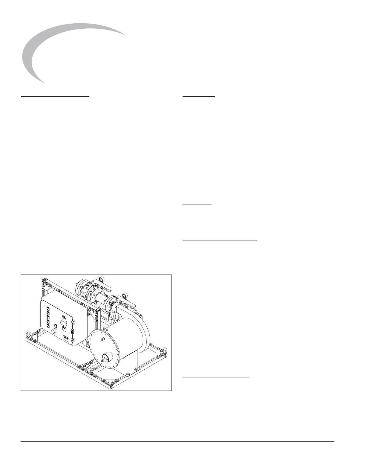
Product Description
The Eclipse BoostPak is designed for installations when
the gas pressure to a building is inadequate to operate the
appliances. It provides a reliable cost-effective packaged
solution for pumping low natural gas supply pressures up
to meet the requirements of high performance combustion
equipment. The discharge pressure is the total of the
booster added pressure plus the incoming gas pressure.
The BoostPak is a completely integrated skid mounted
package. It is factory assembled, wired, tested, and ready
for field power and gas connections. The system includes
but is not limited to a hermetically sealed centrifugal type
gas booster blower, check valve, gas pressure switch,
isolating valves, inlet and outlet piping and flange
connectors, pressure gauges, and control system all
mounted, assembled, wired, and tested. All essential
components for automatic operation are enclosed in an
industrial control panel designed to meet local and
national electrical codes.
Various standard options may be selected to configure a
complete model number. The options determine the
control modes, pressure boost, flow, and environmental
conditions.
Figure 1.1. Eclipse BoostPak
Audience
This manual has been written for personnel already
familiar with all aspects of a gas booster system and it’s
add-on components.
These aspects are:
• Installation
• Use
• Maintenance
• Safety
The audience is expected to be qualified and have
experience with this type of equipment and its working
environment.
Purpose
The purpose of this manual is to make sure that you carry
out the installation of a safe, effective and trouble-free
system.
BoostPak Documents
Installation Guide No. 630-2
• This document
Datasheet No. 630-2
• Available for BoostPak model MS
• Provides assembly drawing numbers
• Required to complete installation
Datasheet No. 630-3
• Available for BoostPak model MR
• Provides assembly drawing numbers
• Required to complete installation
Datasheet No. 630-4
• Available for BoostPak model MH
• Provides assembly drawing numbers
• Required to complete installation
Related Documents
• EFE 825 (Combustion Engineering Guide)
• Eclipse Bulletins and Information Guides: 620, 710,
780, 904 (MH only), 925 (MH only), 940
4
Eclipse Packaged Gas BoostPak, V2, Installation Guide 630-2, 6/22/2010
Page 5

Safety
2
Important notices for safe operation of the BoostPak
system will be found in this section. To avoid personal
injury, damage to property or the facility, the following
warnings must be observed. Read this entire manual
before attempting to start the system. If any part of the
information in this manual is not understood, contact
Eclipse before continuing.
Safety Warnings
DANGER
Ŷ The BoostPak packaged gas booster systems,
covered by this guide are designed to increase gas
pressure to a gas utilization appliance. All fuel
handling devices are capable of producing fires
and explosions if improperly applied, installed,
adjusted, controlled or maintained.
Ŷ Do not bypass any safety feature; fire or explosion
could result.
Ŷ Never try to operate a BoostPak if it shows signs
of damage or malfunction.
Capabilities
Only qualified personnel, with good mechanical aptitude
and experience with combustion equipment, should
adjust, maintain or troubleshoot any mechanical or
electrical part of this system.
Operator Training
The best safety precaution is an alert and trained
operator. Train new operators thoroughly and have them
demonstrate an adequate understanding of the
equipment and its operation. A regular retraining schedule
should be administered to ensure operators maintain a
high degree of proficiency.
Replacement Parts
Order replacement parts from Eclipse only. Any customer
supplied valves or switches should carry UL, FM, CSA,
CGA and/or CE approvals where applicable.
NOTICE
Ŷ This manual provides information in the use of the
BoostPak for its specific design purpose. Do not
deviate from any instructions or application limits
described herein without written advice from
Eclipse.
Eclipse Packaged Gas BoostPak, V2, Installation Guide 630-2, 6/22/2010
5
Page 6

Installation
3
Introduction
In this chapter you will find information and instructions
needed to install the BoostPak and system components.
The system drawings are shipped with the BoostPak.
Refer to the data sheet for the drawing number and
contact Eclipse for a replacement.
WARNING
Ŷ All installation work must be carried out in
compliance with current legislated standards.
Handling & Storage
Handling
• Make sure the area is clean.
• Inspect the system, ensure that all components are
clean and free from damage.
• Use appropriate support and handling equipment
when lifting the BoostPak.
• Protect the components from weather, damage, dirt
and moisture.
• Protect the system and components from excessive
temperatures and humidity.
around the BoostPak in order to facilitate servicing and
field replacement of components. Avoid obstructing the
open access to the control panel.
NOTE:
from the front of the control panel door and the swing of
the door should not be obstructed from opening 120°. If
local codes are different than these requirements, those
codes should be adhered to during installation.
There should be no less than 36" of clearance
Environment
Be sure the operating environment matches the original
operating specifications. Check the following items:
• Voltage, frequency, and stability of electrical power
• Ambient temperature and humidity
• Area classification (non-hazardous or hazardous)
• Exposure to sunlight, water, ice, wind, and vibration
Mechanical Installation
Lift Points
Use lifting lugs on mounting base for all lifting. Do not use
piping or supports as lift points unless designated by
manufacturer labeling.
Mounting
Storage
• Make sure the components are clean and free of
damage.
• Store the components in a cool, clean, dry room.
• After making sure everything is present and in good
condition, keep the components in original
packages as long as possible.
Checklist Before Installation
Placement
The Eclipse BoostPak is completely factory piped, wired
with controls, tested and ready for field connections. The
system should be installed in an accessible ventilated
location on a level concrete floor or substantial mounting
pad. Place the BoostPak to avoid excessive numbers of
bends and fittings in the interconnecting piping.
Access
The BoostPak location must allow easy accessibility for
inspection and maintenance. Provide adequate space all
6
Bolt the unit base securely using the mounting holes
provided in the BoostPak base.
Piping Installation
Gas Piping
All gas piping must be done in accordance with the
national fuel gas code, local utility company and municipal
agency requirements. Protect and prevent contamination
of the piping during installation.
NOTE:
devices are properly oriented with respect to flow direction
and vertical (gravity) orientations.
NOTE:
unnecessary fittings, and excessive bends that may
cause additional flow restriction and pressure loss.
Elbows within 5 pipe diameters may reduce pressure and
capacity below operating requirements.
Eclipse Packaged Gas BoostPak, V2, Installation Guide 630-2, 6/22/2010
If it is necessary to redirect piping, make sure all
Avoid severe size reductions in pipe connections,
Page 7

Piping Support
WARNING
Leak Testing
Use brackets or hangers to support the gas piping. If you
have questions, consult your local gas company.
Initial Fitting
• Remove any shipping materials and inspect for
foreign objects in the piping.
• Connect inlet gas piping from the utility supply to the
inlet flange as indicated by directional arrows and
system drawings.
• Connect the gas pipe requiring the boosted gas
pressure feeding your appliance to the discharge
gas pipe outlet flange, also indicated by label and
system drawing.
Vent Piping
The model MS, MR and MH BoostPaks do not require
vent piping. Vent piping may be required for components
added to the system. Check the individual product data
sheets for specific manufacturer’s recommendations.
Inlet Low Gas Manual Reset Pressure Switch
This switch may come already mounted and wired on the
BoostPak, or it may be supplied as a kit to be remotely
mounted. Install loose inlet gas low pressure switch kit in
location determined by the utility company. Normally it is
located downstream of the main regulator just inside the
building where the supply pipe enters.
Inlet High Gas Pressure Switch
If used, this optional switch may come already mounted
and wired on the BoostPak, or it may be supplied as a kit
to be remotely mounted. Install loose inlet gas high
pressure switch kit in location determined by the
specifying engineer. Normally it is located downstream of
the main regulator just inside the building where the
supply pipe enters.
Pressure Switch Settings
• Check and adjust the pressure switches as
required.
• The utility company dictates the setting of the low
inlet gas pressure switch typically at 3-4" w.c. to
prevent operation when there is insufficient gas
volume.
• The discharge gas pressure switch should be set 24" w.c. below the rated discharge pressure at the
maximum flow conditions for the site application.
• If installed, the optional inlet high gas pressure
switch should be set to 90% of the pressure where
the sum of the inlet plus the rated boost equals the
maximum rating of downstream equipment.
(Alternately it can be set to 20% above the minimum
requirement of the downstream equipment.)
The BoostPak is tested and leak tight at the factory,
however, shipping and installation may cause joints to
loosen. Check and test all piping for leaks.
Ŷ Test pressure must not exceed 5 PSIG and the
pressure gauges or any components with ratings
less than the test pressure should first be isolated.
Check the individual product datasheets for
specific ratings.
Electrical Installation
General
All electrical wiring must be done in accordance with the
national electrical code, local utility company and
municipal agency requirements. The schematics are
shipped with the BoostPak. Contact Eclipse for
replacement, drawing 10025020.
The BoostPak is pre-wired and therefore only the
electrical power supply and any externally supplied
control devices must be terminated. Depending on the
specific model configuration, the external devices can
include the appliance run interlock contact and the low
inlet gas pressure switch.
Review Name Plate
Before making any electrical connections, compare the
electrical supply circuit ratings at the installation site to
those on the nameplates of the BoostPak, control panel,
booster and (MH only) heat exchanger motor(s). The
supply for the BoostPak model MS/MR/MH varies based
on booster and motor option, and may be 120VAC,
208VAC, 230VAC or 460VAC nominal and must be
capable of supplying the booster and (MH only) heat
exchanger motor full load current and starting current.
Terminal Check
During shipment, the control panel terminals may have
loosened. Check the tightness of all connections in the
panel and at the pressure switches.
Supply Power Wiring
The incoming power to the control panel must be wired
into the terminals as designated in the schematic diagram.
Earth ground must be connected to terminal G.
Wiring for Continuous Operation
This control mode allows an operator to turn a local
control panel switch on when pressure boost is needed
and turn the switch off when the boost is not needed. For
this mode, a jumper is installed between terminals 1321
and 2161.
Eclipse Packaged Gas BoostPak, V2, Installation Guide 630-2, 6/22/2010
7
Page 8

Wiring for Appliance On Demand Operation,
Start Circuit Interlock
This control mode requires a customer supplied run
interlock. It must be a dry (voltage free) contact that
makes continuity when the booster is required and opens
when the booster should shut down. Commonly used
devices include: automatic time clock, flow switch, relay
contact, or switch contact. For this mode, wire the contact
between terminals 1321 and 2161. Be sure to remove any
jumper connection between terminals if present.
Wiring for Flow Sensor Demand Control
Operation
This control mode is an option that is typically ordered and
installed at the factory. If it has been supplied as a kit, refer
to Data 630-FC and Installation Guide 630-FC.
Wiring for Inlet Low Gas Manual Reset
Pressure Switch
This switch may come already mounted and wired on the
BoostPak, or it may be supplied as a kit to be remotely
mounted. This switch is required by local utility company
as a safety device. The kit version must be wired into the
BoostPak control panel. Wire the low inlet gas pressure
switch terminal 3 (COM) to panel terminal 1321, and
switch terminal 2 (NO) to panel terminal 2121. Be sure to
remove any jumper connection between these terminals if
present.
Checklist After Installation
Ensure the system was properly installed and verify:
• The skid is securely bolted to the floor or mounting
pad and is rigid and level.
• There are no loosely mounted components.
• There are no leaks in the gas lines.
• The external gas piping has appropriate brackets
and is not supported by the BoostPak.
• Verify correct orientation of gas piping – from utility
point of entry to BoostPak inlet, from BoostPak
outlet to the appliance.
• Verify sufficient unobstructed access to the control
panel and booster and (MH only) heat exchanger
motor(s).
• Verify electrical power supply and all external
devices are wired correctly.
• Verify tightness of all terminal connections on all
devices.
• Verify the gas pressure switch(es) are installed in
the correct location and confirm the proper settings.
• Verify all device orientations are correct with respect
to flow direction.
Wiring for Inlet High Gas Pressure Switch
If installed, this optional switch may come already
mounted and wired on the BoostPak, or it may be supplied
as a kit to be remotely mounted. The kit version must be
wired into the BoostPak control panel. Wire the high inlet
gas pressure switch terminal 3 (COM) to panel terminal
2161, and switch terminal 1 (NC) to panel terminal 2162.
Be sure to remove the jumper wire between these
terminals if present.
Alarm Output Wiring
A terminal is provided to connect an external alarm. If
used, wire the external alarm to panel terminal 2331 (hot)
and 1323 (neutral). The external alarm should be rated for
120VAC and not exceed 2 amps.
8
Eclipse Packaged Gas BoostPak, V2, Installation Guide 630-2, 6/22/2010
Page 9

Commissioning
4
Introduction
In this chapter you will find information and procedures for
the first operation and adjustment of the BoostPak.
WARNING
Ŷ Only qualified personnel, with good mechanical
and electrical aptitude should adjust, maintain, or
troubleshoot any mechanical or electrical part of
this system. They should have knowledge and
experience with combustion equipment including
piping, valves, motors, blowers, boosters,
switches, control panels and wiring.
These instructions rely on the expertise of the person
performing the start up. If you do not understand any
portion of this procedure or do not feel qualified, stop and
call Eclipse.
Applying Power
Before applying the site electrical power supply to the
BoostPak control panel:
• Turn off the main disconnect switch.
• Turn the HAND/OFF/AUTO control switch to OFF.
Motor Rotation Check
Ensure that the booster gas supply is off and the booster
has no gas under pressure in it. Remove the pipe plug in
the observation port on the booster body. Turn the control
panel main disconnect switch on and verify that the panel
instrumentation has power. Momentarily turn the MAN/
OFF/AUTO switch to MAN position to “bump” the motor
starter such that the motor just starts to turn and rotates
slowly. Observe the direction of rotation of the fan blades
through the observation port. They should be turning in
the direction indicated by the rotation arrow on the
booster. If rotation direction is incorrect, have a qualified
electrician rewire the incoming power for the proper
direction.
Turn on the gas supply to the BoostPak and press the
reset on the Inlet Low Gas Manual Reset Pressure
Switch.
Operational Tests
Test the operation of the BoostPak and verify:
• DISCHARGE PRESSURE SWITCH: The low gas
light and alarm comes on with the outlet valve
closed. The booster should remain running.
• LOW INLET GAS PRESSURE SWITCH: The
booster stops, the low gas light and alarm comes on
when the Inlet Low Gas Manual Reset Pressure
Switch is adjusted above the inlet gas supply. Adjust
this switch back to the original specified set point
and observe that the system will not restart unless
the pressure switch is first manually reset.
• APPLIANCE RUN INTERLOCK: For appliance on
demand operation mode, turn the control switch to
AUTO and test that the system runs when the
appliance interlock makes contact.
Verify Settings
1. Run system at nominal flow rating.
2. Verify pressure increase from booster is correct. Read
the inlet and outlet pressure gauges on the BoostPak.
Subtract the inlet from outlet pressure to verify added
pressure agrees with the datasheet.
3. Verify that outlet pressure is sufficient for appliance
operation.
4. Verify flow is sufficient for appliance via gas metering
located at the appliance (not included with BoostPak).
5. Run system to minimum flow condition; verify flows
and pressures within acceptable range. For model
MR or MH BoostPak, verify that recirculation flow is
sufficient to keep outlet pipe surface temperature
below 160°F.
6. Record all setup data as an aid for future
troubleshooting and setup operations.
Applying Gas Supply
Before applying the site gas supply, reinstall the pipe plug
and initially set the manual butterfly valves:
• Open the booster inlet valve
• Close the booster outlet valve
• Close the heat exchanger isolation valves (MH only)
Eclipse Packaged Gas BoostPak, V2, Installation Guide 630-2, 6/22/2010
9
Page 10

Commissioning Record
Models MS/MR/MH
Nameplate Information
Mechanical Installation
Low Inlet Gas Pressure Switch Setting ______________
High Inlet Gas Pressure Switch Setting ______________
Performance
BoostPak Outlet Pressure, Low Flow ______________
BoostPak Model ______________
Serial Number ______________
Control Panel Serial Number ______________
Ambient Temperature ______________
Mounting Secure, Rigid, Level ______________
Supply and Feed Piping Supported ______________
Leak Test ______________
Outlet Gas Pressure Switch Setting ______________
Gas Inlet Pressure ______________
BoostPak Outlet Pressure, High Flow ______________
Power Supply Voltage ______________
Booster Motor Current ______________
MR only: Position of Manual BV ______________
MH only: Heat Exchanger Motor Current ______________
Temperature Control Settings (Next Page)
Rotary Actuator Settings (Next Page)
10
Eclipse Packaged Gas BoostPak, V2, Installation Guide 630-2, 6/22/2010
Page 11

MH Models Temperature
Control Settings
SETUP FUNCTION FACTORY
ALGOR CTRALG PDMR _______________
TUNING PB 6 _______________
OUTALG OUTALG RLY _______________
INPUT1 IN1TYP JL _______________
CONTRL ACTION DIR _______________
OPTION AUXOUT OUT _______________
ALARMS A1S1TY DE _______________
Controller Set Point: 120 _______________
MR 45 _______________
RATE 0 _______________
BRNOUT UP _______________
A1S1VA 5.0 _______________
A1S1HL HIGH _______________
ALHTST 0.3 _______________
Parameters not listed here are set at default values found in Installation Guide 925.
MH Models Rotary
Actuator Settings
PARAMETER CODE FACTORY
LF 15T 0 _______________
HF 15S 90 _______________
LO 12T 0 _______________
(C6) 6 6 _______________
(C0) 10 10 _______________
Parameters not listed here are set at default values found in Installation Guide 904.
Eclipse Packaged Gas BoostPak, V2, Installation Guide 630-2, 6/22/2010
11
Page 12

Operation
5
Introduction
In this chapter, you will find instructions on how to start
and stop the booster system. Become familiar with
booster control methods before operating the equipment.
DANGER
Ŷ The BoostPak system, described herein, is
designed to increase gas pressure to an appliance.
All fuel handling devices are capable of producing
fires and explosions if improperly applied,
installed, adjusted, controlled, or maintained.
Ŷ Do not bypass any safety feature; fire or explosion
could result. Never try to operate a BoostPak if it
shows signs of damage or malfunction.
1. Be sure the inlet and outlet valves are open. On model
MH, make sure both heat exchanger isolation valves
are open.
2. Turn the main disconnect switch on.
The green POWER ON light comes on.
3. Check for ALARM conditions and correct before
proceeding.
heat exchanger loop to keep the outlet gas temperature
below this maximum value.
Alarm Silence
To silence the alarm, press the ALARM SILENCE button.
Shutdown
The booster can be stopped by:
• Opening the run interlock contact (appliance
dedicated control mode)
• Turning the control switch to off
• Turning the main disconnect switch off
When shutting the system down to prevent operation, turn
the main disconnect switch off and turn off the main power
supply to the control panel.
4. Turn the control switch to AUTO.
The BoostPak is in operation.
• For Continuous Operation mode, the booster will
run within 15 seconds of the switch operation.
• For Appliance On Demand mode, the booster will
run within 15 seconds of the closure of the
appliance run interlock contact.
The booster motor starter contact closes, the motor starts
running, and the yellow BOOSTER ON light comes on.
The LOW GAS light will flash on and off until the outlet gas
pressure switch makes contact. If it does not make contact
within 15 seconds, the red LOW GAS light comes on
steady and the alarm sounds.
Heat Exchanger Loop Operation
For model MH, the heat exchanger will operate when the
temperature sensed in the outlet pipe exceeds the set
point and deviation alarm value, which is 125°F with
factory default settings. The temperature controller
adjusts the position of the automatic butterfly valve in the
12
Eclipse Packaged Gas BoostPak, V2, Installation Guide 630-2, 6/22/2010
Page 13

Maintenance &
Troubleshooting
6
Monthly Checklist
• Inspect and tighten loose mechanical components
• Look for signs of damage and repair
• Test operation if the unit has not run and check for
excessive vibration
• Clean the booster motor housing
• Clean the heat exchanger, its motor, and cooling fan
(MH only)
• Wipe clean the control panel surfaces
Yearly Checklist
• Check inlet and outlet pressure switch settings
• Check and compare inlet and outlet pressures to the
initial commissioning record sheet
• Measure and compare the power supply and motor
current to the record sheet
• Perform operational test in the commissioning
section of this guide
Problem Possible Cause Solution
No POWER ON light Main supply power is off Be sure main power to the system is
Main disconnect switch is off Turn the control panel main disconnect
Loose connection Check for voltage on panel terminals,
Blown fuse Verify that all fuses are good and
Cannot initiate start sequence Inlet low gas manual reset pressure
switch has activated
Alarm Conditions
Certain conditions will cause the ALARM to come on. To
silence the alarm, press the ALARM SILENCE push
button.
• INLET LOW GAS MANUAL RESET PRESSURE
SWITCH opens due to low utility line pressure. The
LOW GAS light comes on and the booster motor will
stop running. When the pressure is restored, this
switch must be manually pushed to reset its contact.
• DISCHARGE GAS PRESSURE SWITCH fails to
make contact within 15 seconds. The LOW GAS
light comes on; the booster will not shut down.
• If the motor wiring or internal temperature switch
opens, then the motor will stop causing the
discharge gas pressure switch to open. Then the
ALARM and LOW GAS light come on.
• A booster motor overload condition will shut down
the booster and the MOTOR FAULT light and
ALARM will come on.
• A heat exchanger motor overload condition will shut
down the heat exchanger fan and the MOTOR
FAULT light and ALARM will come on (MH only).
switched “on”.
switch on.
turn off main power and inspect,
tighten wire connection.
properly installed. If blown, have a
qualified electrician determine the
cause and fix before replacing fuse.
Check incoming gas pressure: adjust if
necessary.
Check pressure switch setting and
operation.
If used, check that the pressure switch
isolating valve is not closed.
Eclipse Packaged Gas BoostPak, V2, Installation Guide 630-2, 6/22/2010
13
Page 14

Problem Possible Cause Solution
Cannot initiate start sequence If used, Inlet High Gas Pressure Switch
has activated
Normal operation, when the inlet
pressure drops below the switch
setting, then the system will start.
Motor starter overload tripped Check for defective motor, reset
overload unit.
Startup sequence runs, but booster
shuts down after several minutes
Appliance interlock not made or jumper
(continuous operation) is loose
Booster motor overload, thermal cutout switch open
Have qualified electrician verify and
rewire.
Verify voltage supply, booster motor
rotation direction, sufficient inlet
pressure, and that inlet/outlet valves
are open. Let motor cool and reset
overload.
Cannot achieve full capacity Inlet/outlet piping too restricted Rerun larger/straighter pipe runs.
Inlet pressure too low Consult with utility company.
Booster motor rotation incorrect Verify and have qualified electrician
rewire.
Manual inlet or outlet valve is partially
Open inlet/outlet valves fully.
closed
Cooling loop control valve too wide
open (MR/MH only)
See OPERATIONAL TESTS in the
COMMISSIONING section. Check
ACT parameters (MH only). Check for
missing or loose coupling, damaged
butterfly valve.
Recirculation loop or heat exchanger
loop is providing insufficient cooling
Actuator settings incorrect,
temperature controller settings
Verify Parameters
incorrect
Butterfly/actuator coupling loose; not
Check and Reinstall.
tracking
Isolation valves not fully open (MH
Open inlet/outlet isolation valves fully.
only)
14
Eclipse Packaged Gas BoostPak, V2, Installation Guide 630-2, 6/22/2010
Page 15

BoostPak Model MS, MR, and MH Wiring Diagram
Phantom componnents marked 1
are installed on BoostPak models
with the heat exchanger option.
Phantom Components Marked 2
are installed on BoostPak models
with the flow control option. The flow
control contact is set to close when
gas fired equipment causes flow.
Notes:
Phantom components marked 3
are installed on BoostPak models
with the high inlet gas pressure
switch option. Set@value above
which the downstream appliance
can operate. Auto reset.
Phantom components marked 4
are installed on BoostPak models
using 3 phase power.
Phantom components marked 6
are used when the motor thermal
overloads are required. Reference
the MTR. section charts on page 24.
Phantom component marked 7 is
installed on BoostPak models using
the customer supplied appliance
run interlock dry contact.
Phantom component marked 8 is
the optional customer alarm.
Maximum current is 2 amps.
1
2
3
4
6
7
8
SIMPLEX BOOSTPAK
317FCM
FLOW
CONTROL
MODULE
G
MTR
THERMAL OL
REFERENCE THE
HEAT EXCH. MTR
SELECTION CHART
FOR MOTOR WIRING
AND FLA
THERMOCOUPLE
ACTUATOR
TYPE “J”
311 ACT
ROTARY
P1
P2
P1
7
8
3
2
P2
RED
SEPARATE
CONDUIT
2
1
G
2
1
G
119T1
119T2
119T3
CONTROL PANEL
SHIELD
G
MAIN
1321
1323
1321
2161
G
*
2041
TB1
TERM
2042
STRIP
2 T1
4 T2
6 T3
26
TEMPERATURE
CONTROLLER
27
1321
1323
GND
*
TB1
3071
TERM
STRIP
3081
SHD
SINGLE
PHASE
DETAIL “A”
*
TB1
TERM
STRIP
304 MS
HEAT
EXCHANGER
MOTOR
STARTER
303 TC
SINGLE
PHASE
W/UPS
DETAIL “B” DETAIL “C”
1L1 3L2 5L3
4T26T3
2T1
TERM
STRIP
237MS
BOOSTER
MOTOR
STARTER
TB1
*
THREE
PHASE
7L4
8T4
2331
1323
1321
2
161
1321
GND
2081
1321
GND
2121
2161
GND
2162
2102
2101
2 T1
4 T2
6 T3
OPTIONAL
CUSTOMER
ALARM
OPTIONAL
CUSTOMER
SUPPLIED
APPLIANCE RUN
INTERLOCK
208 PS
2
3
1
G
212 PS
2
3
1
G
218 PS
2
3
1
G
P1
110T1
110T2
110T3
G
LOW
DISCHARGE GAS
AUTO RESET
PRESSURE SWITCH
(SEE NOTE 12)
LOW INLET GAS
MANUAL RESET
PRESSURE SWITCH
(SEE NOTE 11)
HIGH INLET GAS
AUTO RESET
PRESSURE SWITCH
P2
MTR
THERMAL OL
REFERENCE THE
BOOSTER MTR
SELECTION CHART
FOR MOTOR WIRING
AND FLA
Eclipse Packaged Gas BoostPak, V2, Installation Guide 630-2, 6/22/2010
15
Page 16

BoostPak Model MS, MR, and MH Wiring Diagram, Continued
SINGLE PHASE INCOMING POWER WITHOUT THE UPS OPTION
DETAIL “A”
SINGLE PHASE CUSTOMER SUPPLY
104 DISC
MAIN PWR
DISC S
WITCH
DETAIL “B”
SINGLE PHASE INCOMING POWER WITH THE UPS OPTION
SINGLE PHASE CUSTOMER SUPPLY
MAIN POWER
DISCONNECT
TB1
TERMINAL STRIP
THREE PHASE INCOMING POWER
104DISC
MAIN POWER
DISCONNECT
SWITCH
TB1
TERM STRIP
104 DISC
SWITCH
DETAIL “C”
THREE PHASE CUSTOMER SUPPLY
MAIN
CONTROL PANEL
104 UPS
REFERENCE
DETAILS “D”
AND “G”
FOR PROPER
UPS WIRING
USED WHEN THE BOOSTPAK UNIT
DETAIL “F”
IS MOUNTED INSIDE AND THE
BOOSTER MOTOR IS 1/2 OR 3/4 HP
7000VA/208/230V
MGE #HV EX 7RT
JUMPER
DETAIL “G”
USED WHEN THE BOOSTPAK UNIT
IS MOUNTED INSIDE AND THE
BOOSTER MOTOR IS 1 HP
11000VA/208/230V
MGE #HV EX 11RT
JUMPER
104 UPS
NORMAL AC
SOURCE
BYPASS AC
SOURCE
OUTPUT
104 UPS
NORMAL AC
SOURCE
BYPASS AC
SOURCE
OUTPUT
JUMPER
104 DISC
MAIN PWR
DISC SWITCH
NOTES:
Phantom components marked 5
5
are installed on BoostPak models
with the UPS option.
Eclipse External Wiring
Customer Field Wiring
Te rminal Block
Te rminal on Device
Panel Ground Lug
Used to define the different options available.
16
Eclipse Packaged Gas BoostPak, V2, Installation Guide 630-2, 6/22/2010
Page 17

Booster Motor Voltage
115 VAC/1 PHASE/60HZ 208 VAC/1 PHASE/60 HZ
1/4
HP
1/2
HP
3/4
HP
1
HP
2
HP
230 VAC/1 PHASE/60 HZ 208 VAC/3 PHASE/60 HZ
230 VAC/3 PHASE/60 HZ
460 VAC/3 PHASE/60 HZ
5
HP
Heat Exchanger Motor Voltage
115 VAC/1 PHASE/60HZ
1/2
HP
208 VAC/1 PHASE/60 HZ
230 VAC/1 PHASE/60 HZ 208 VAC/3 PHASE/60 HZ
230 VAC/3 PHASE/60 HZ
460 VAC/3 PHASE/60 HZ
Eclipse Packaged Gas BoostPak, V2, Installation Guide 630-2, 6/22/2010
17
Page 18

Panel Layout and Enclosure
G
Y
Y
R
B
Innovative Thermal Solutions
Eclipse Combustion
Rockford, Illinois, U.S.A.
www.eclipsenet.com
Enclosure 16”H x 20”W x 8”D
100
70
18
80
90
Internal View, Panel 13”H x 17”W
Eclipse Packaged Gas BoostPak, V2, Installation Guide 630-2, 6/22/2010
Page 19

BoostPak Model MS Piping Schematic
Outlet
Inlet
BoostPak Model MR Piping Schematic
Outlet
Inlet
BoostPak Model MH Piping Schematic
Outlet
Inlet
Eclipse Packaged Gas BoostPak, V2, Installation Guide 630-2, 6/22/2010
19
Page 20

Appendix
Conversion Factors
Metric to English
From To Multiply By
cubic meter (m³) cubic foot (ft³) 35.31
cubic meter/hr (m³/h) cubic foot/hr (cfh) 35.31
degrees Celsius (°C) degrees Fahrenheit (°F) (°C x 9/5) + 32
kilogram (kg) pound (lb) 2.205
kilowatt (kW) BTU/hr 3415
meter (m) foot (ft) 3.281
millibar (mbar) inches water column ("w.c.) 0.402
millibar (mbar) pounds/sq in (psi)
millimeter (mm) inch (in) 3.94 x 10
MJ/Nm³ BTU/ft³ (standard) 26.86
Metric to Metric
14.5 x 10
-3
-2
English to Metric
cubic foot/hour (cfh) cubic meter/hour (m³/h) 2.832 x 10
degrees Fahrenheit (°F) degrees Celsius (°C) (°F - 32) x 5/9
inches water column ("w.c.) millibar (mbar) 2.489
From To Multiply By
kiloPascals (kPa) millibar (mbar) 10
meter (m) millimeter (mm) 1000
millibar (mbar) kiloPascals (kPa) 0.1
millimeter (mm) meter (m) 0.001
From To Multiply By
cubic foot (ft³) cubic meter (m³) 2.832 x 10
pound (lb) kilogram (kg) 0.454
BTU/hr kilowatt (kW) 0.293 x 10
foot (ft) meter (m) 0.3048
pounds/sq in (psi) millibar (mbar) 68.95
inch (in) millimeter (mm) 25.4
BTU/ft³ (standard) MJ/Nm³ 37.2 x 10
-2
-2
-3
-3
i
Page 21

System Schematics
Key to System Schematics
Symbol Appearance Name Remarks
Hermetic Booster Booster is used to increase gas
pressure.
Bulletin/
Info Guide
630-1
Control Panel The control panel encloses the
booster motor starter, smart replay/
PLC, disconnect and indicator lights
for BoostPak operation.
Check Valve A check valve permits flow only in
one direction and is used to prevent
back flow of gas.
Pressure Switch A switch activated by rise or fall in
pressure. A manual reset version
requires pushing a button to transfer
the contacts when the pressure
setpoint is satisfied.
Pressure Gauge A device to indicate pressure. 940
Gas Cock Gas cocks are used to manually shut
off the gas supply.
Butterfly Valve Butterfly valves are used to either
manually or automatically control the
flow of gas.
Heat Exchanger Forced air to gas cooler removes
excess heat that is generated in the
booster.
630-1
780
Dungs
80110
710
Thermocouple A sensor for measuring gas
Flexible Connector Isolates booster from vibration,
Eclipse Packaged Gas BoostPak, V2, Installation Guide 630-2, 6/22/2010
temperature.
mechanical, and thermal stresses.
ii
Page 22

Offered By:
Power Equipment Company
2011 Williamsburg Road
Richmond, Virginia 23231
Phone (804) 236-3800
Fax (804) 236-3882
www.peconet.com
 Loading...