

Page 1

Design Guide 163
6/19/2012
Eclipse AH-MA DualBlock
Burners
Air Make Up Series
Version 1
Page 2
Copyright
Copyright 2007 by Eclipse, Inc. All rights reserved
worldwide. This publication is protected by federal
regulation and shall not be copied, distributed,
transmitted, transcribed or translated into any human or
computer language, in any form or by any means, to any
third parties, without the express written consent of
Eclipse, Inc.
other injury, loss, damage or expenses, whether direct or
consequential, including but not limited to loss of use,
income, or damage to material arising in connection with
the sale, installation, use of, inability to use, or the repair
or replacement of Eclipse’s products.
Any operation expressly prohibited in this manual, any
adjustment, or assembly procedures not recommended or
authorized in these instructions shall void the warranty.
Disclaimer Notice
In accordance with the manufacturer’s policy of continual
product improvement, the product presented in this
brochure is subject to change without notice or obligation.
The material in this manual is believed adequate for the
intended use of the product. If the product is used for
purposes other than those specified herein, confirmation
of validity and suitability must be obtained. Eclipse
warrants that the product itself does not infringe upon any
United States patents. No further warranty is expressed or
implied.
Liability & Warranty
We have made every effort to make this manual as
accurate and complete as possible. Should you find errors
or omissions, please bring them to our attention so that we
may correct them. In this way we hope to improve our
product documentation for the benefit of our customers.
Please send your corrections and comments to our
Marketing Communications Manager.
It must be understood that Eclipse’s liability for its product,
whether due to breach of warranty, negligence, strict
liability, or otherwise is limited to the furnishing of
replacement parts and Eclipse will not be liable for any
Document Conventions
There are several special symbols in this document. You
must know their meaning and importance.
The explanation of these symbols follows below. Please
read it thoroughly.
How To Get Help
If you need help, contact your local Eclipse representative.
You can also contact Eclipse at:
1665 Elmwood Rd.
Rockford, Illinois 61103 U.S.A.
Phone: 815-877-3031
Fax: 815-877-3336
http://www.eclipsenet.com
Please have the information on the product label available
when contacting the factory so we may better serve you.
www.eclipsenet.com
Product Name
Item #
S/N
DD MMM YYYY
This is the safety alert symbol. It is used to alert you to potential personal
injurt hazards. Obey all safety messages that follow this symbol to avoid
possible injury or death.
Indicates a hazardous situation which, if not avoided, will result in death
or serious injury.
WARNING
CAUTION
NOTICE
NOTE
2
Indicates a hazardous situation which, if not avoided, could result in
death or serious injury.
Indicates a hazardous situation which, if not avoided, could result in
minor or moderate injury.
Is used to address practices not related to personal injury.
Indicates an important part of text. Read thoroughly.
Page 3
Table of Contents
1 Introduction............................................................................................................................ 4
Product Description .............................................................................................................. 4
Audience .............................................................................................................................. 4
Purpose................................................................................................................................ 4
AH-MA DualBlock Documents ............................................................................................. 4
Related Documents.............................................................................................................. 4
2 Safety...................................................................................................................................... 5
Safety Warnings ................................................................................................................... 5
Capabilities........................................................................................................................... 5
Operator Training ................................................................................................................. 5
Replacement Parts...............................................................................................................5
3 System Design....................................................................................................................... 6
Design .................................................................................................................................. 6
Step 1: Burner Option Selection........................................................................................... 6
Step 2: Blower Option Selection........................................................................................... 8
Step 3: Control Methodology................................................................................................ 8
Step 4: Ignition System ........................................................................................................ 9
Step 5: Flame Monitoring Control System............................................................................ 9
Step 6: Main Gas Shut-Off Valve Train ................................................................................ 10
Step 7: Process Temperature Control System..................................................................... 10
Appendix ................................................................................................................................... i
Conversion Factors ..............................................................................................................i
Key to Schematics................................................................................................................ ii
Eclipse AH-MA DualBlock Burner, V2, Design Guide 163, 6/19/2012
3
Page 4
Introduction
1
Product Description
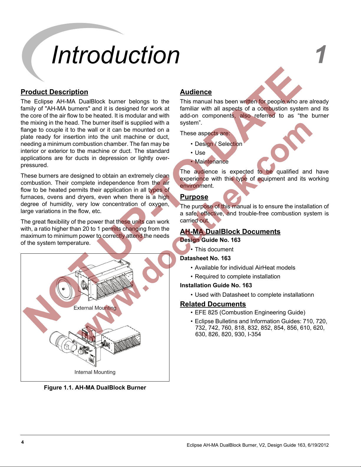
The Eclipse AH-MA DualBlock burner belongs to the
family of "AH-MA burners" and it is designed for work at
the core of the air flow to be heated. It is modular and with
the mixing in the head. The burner itself is supplied with a
flange to couple it to the wall or it can be mounted on a
plate ready for insertion into the unit machine or duct,
needing a minimum combustion chamber. The fan may be
interior or exterior to the machine or duct. The standard
applications are for ducts in depression or lightly over-
pressured.
These burners are designed to obtain an extremely clean
combustion. Their complete independence from the air
flow to be heated permits their application in all types of
furnaces, ovens and dryers, even when there is a high
degree of humidity, very low concentration of oxygen,
large variations in the flow, etc.
The great flexibility of the power that these units can work
with, a ratio higher than 20 to 1 permits changing from the
maximum to minimum power to correctly attend the needs
of the system temperature.
External Mounting
Audience
This manual has been written for people who are already
familiar with all aspects of a combustion system and its
add-on components, also referred to as “the burner
system”.
These aspects are:
• Design / Selection
• Use
• Maintenance
The audience is expected to be qualified and have
experience with this type of equipment and its working
environment.
Purpose
The purpose of this manual is to ensure the installation of
a safe, effective, and trouble-free combustion system is
carried out.
AH-MA DualBlock Documents
Design Guide No. 163
• This document
Datasheet No. 163
• Available for individual AirHeat models
• Required to complete installation
Installation Guide No. 163
• Used with Datasheet to complete installationn
Related Documents
• EFE 825 (Combustion Engineering Guide)
• Eclipse Bulletins and Information Guides: 710, 720,
732, 742, 760, 818, 832, 852, 854, 856, 610, 620,
630, 826, 820, 930, I-354
Internal Mounting
Figure 1.1. AH-MA DualBlock Burner
4
Eclipse AH-MA DualBlock Burner, V2, Design Guide 163, 6/19/2012
Page 5

Safety
Important notices which help provide safe burner
operation will be found in this section. To avoid personal
injury and damage to the property or facility, the following
warnings must be observed. All involved personnel
should read this entire manual carefully before attempting
to start or operate this system. If any part of the
information in this manual is not understood, contact
Eclipse before continuing.
Safety Warnings
DANGER
■ The burners, described herein, are designed to
mix fuel with air and burn the resulting mixture. All
fuel burning devices are capable of producing fires
and explosions if improperly applied, installed,
adjusted, controlled or maintained.
■ Do not bypass any safety feature; fire or explosion
could result.
■ Never try to light a burner if it shows signs of
damage or malfunction.
2
NOTICE
■ This manual provides information regarding the
use of these burners for their specific design
purpose. Do not deviate from any instructions or
application limits described herein without written
approval from Eclipse.
Capabilities
Only qualified personnel, with sufficient mechanical
aptitude and experience with combustion equipment,
should adjust, maintain or troubleshoot any mechanical or
electrical part of this system.
Operator Training
The best safety precaution is an alert and trained
operator. Train new operators thoroughly and have them
demonstrate an adequate understanding of the
equipment and its operation. A regular retraining schedule
should be administered to ensure operators maintain a
high degree of proficiency.
WARNING
■ The burner and duct sections are likely to have
HOT surfaces. Always wear the appropriate
protective equipment when approaching the
burner.
■ Eclipse products are designed to minimize the use
of materials that contain crystalline silica.
Examples of these chemicals are: respirable
crystalline silica from bricks, cement or other
masonry products and respirable refractory
ceramic fibers from insulating blankets, boards, or
gaskets. Despite these efforts, dust created by
sanding, sawing, grinding, cutting and other
construction activities could release crystalline
silica. Crystalline silica is known to cause cancer,
and health risks from the exposure to these
chemicals vary depending on the frequency and
length of exposure to these chemicals. To reduce
the risk, limit exposure to these chemicals, work in
a well-ventilated area and wear approved personal
protective safety equipment for these chemicals.
Replacement Parts
Order replacement parts from Eclipse only. All Eclipse
approved valves or switches should carry UL, FM, CSA,
CGA and/or CE approval where applicable.
5
Page 6

System Design
3
Design
When selecting an AH-MA DualBlock burner, choices are
available to define a burner that will be safe and reliable
for the system in which it will be installed. The design
process is divided into the following steps:
1. Burner Option Selection:
• Burner Model / Size Selection
• Burner Style
• Air Supply
• Fuel Type
• Manifold Type
• Mounting Flange
• Burner Configuration
• Gas Pipe Connection
• Control Valve
• Ignition Type
• Flame Supervision
• Control Motor
• Air Flow Switch
2. Blower Option Selection:
5. Flame Monitoring System:
• Flame Sensor
• Flame Monitoring Control
6. Main Gas Shut-Off Valve Train Selection.
• Component Selection
• Valve Train Size
7. Process temperature control system.
NOTE: Information in Datasheet 163 is necessary to
complete some of the procedures.
Step 1: Burner Option Selection
This section describes how to select burner options to suit
an application. Use List 163 and Datasheet 163 when
following this selection process.
CAUTION
■ Consult EFE-825, Eclipse Combustion
Engineering Guide, or contact Eclipse Combustion
if you have special conditions or questions.
Burner Model / Size Selection
Consider the following when selecting the burner size:
• Power Supply Frequency
• Blower Motor Type
• Blower Inlet
• Motor Orientation
• Remote Blower Sizing
• Air Filter
3. Control Methodology:
• Burner Control
4. Ignition System:
• Ignition Transformer
• Trial for Ignition
• Ignition Gas Piping
6
• Heat Input - Calculate the required heat input to
achieve the required heat balance.
• Process Air Temperature - Upstream process air
temperature will determine the housing material
required.
• Combustion Chamber Pressure - Consider the
effects that large or varying chamber pressures
have on burner performance.
• Altitude - Data supplied is based on burner
operation at sea level.
• Combustion Air Supply - Combustion air should
be fresh (20.9% O2) and clean (without corrosives).
• Combustion Air Temperature - Changes in air
supply temperature can affect the burner
performance. The combustion air supply
temperature should not exceed 250° F.
• Fuel Type - Variation in calorific value and density
will affect burner performance.
Eclipse AH-MA DualBlock Burner, V2, Design Guide 163, 6/19/2012
Page 7

Burner Style
AH-MA DualBlock burners are available in straight
sections, double T geometries and cross sections. Select
the geometry that best suits the installation. The housing
material is stainless steel, but for burner sizes above
AB600L model, the housing is manufactured in standard
steel plate. For these sizes, and upstream processing
temperature above 500°F (260°C), please contact
Eclipse.
Air Supply
AH-MA DualBlock burners can be ordered with or without
a combustion air blower directly mounted to the burner.
For remote blower applications, see "Remote Blower
Sizing".
Fuel Type
Table 3.1 Fuel Type
Gross
Fuel Symbol
Natural
Gas
Propane C3H
Butane C4H
BTU/ft3 @ standard conditions (MJ/m3 @ normal conditions)
CH490%+
8
10
Heating
Value
1000 BTU/ft
(40.1 MJ/m
2525 BTU/ft3
(101.2 MJ/m
3330 BTU/ft3
(133.7 MJ/m
Specific
Gravity
3
0.60 1290 BTU/ft
3
)
1.55 2028 BTU/ft
3
)
2.09 2303 BTU/ft
3
)
WOBBE
Index
If using an alternative fuel supply, contact Eclipse with an
accurate breakdown of the fuel components.
Manifold Type
AH-MA DualBlock burners are available with steel gas
manifolds only.
Mounting Flange
Select the mounting hardware best suited to your
application. Hardware is available for External Mounting
on wall duct, and with fixing plate for Internal Mounting
with process or external combustion air inlet.
Burner Configuration
Left hand or right hand piping is available. Configuration is
based on viewing the burner from the air inlet.
Control Valve
AH-MA DualBlock can be supplied with the following
control options:
• Burner System Mounting - The control valve is
sized based on burner input and fuel type.
• Separated Mounting - Order when fuel control
valve cannot be mounted directly to the burner due
to system considerations.
• Less Control Valve - If not supplied by Eclipse,
customer must supply a suitable fuel control valve
capable of suppling fuel in accordance with the
burners operating range.
Ignition Type
Ignition can be by direct spark or spark ignited pilot for
models below AB0400L. Rest of models use by spark
ignited built-in pilot only.
Flame Supervision
Flame supervision is by flame rod or UV scanner.
Depending on configuration selected, flame sensor can
be mounted at either or both ends of the burner.
3
Control Motor
Select a control motor. Standard control motor options
3
include various models which Eclipse will mount to the
burner. Burners can be ordered with control motor bracket
and mounting hardware only. Customer supplied control
3
motors must conform to these specifications:
• Rotation not to exceed 2 rpm. (30 sec / 90° typical)
• Minimum torque of 25 in-lb. (2,8 Nm)
• 90° stroke
• Continuous modulating or high/low modulating
control
• Reversible direction of rotation
• Certain applications may require control motors with
a limit switch or switches if:
- the burner capacity is to be limited to fit an
application
- there is a need to indicate a high and/or low fire
butterfly valve position
Gas Pipe Connection
The piping, burner gas inlet, and fuel modulating valve (if
selected) are threaded using the customer selected pipe
thread option.
Eclipse AH-MA DualBlock Burner, V2, Design Guide 163, 6/19/2012
7
Page 8

Air Flow Switch
The air flow switch provides a signal to the monitoring
system when there is not enough air pressure from the
blower. If a switch is selected, it will be factory mounted.
WARNING
■ Eclipse supports the NFPA regulation requiring, as
a minimum standard for main gas shut-off
systems, the use of an air pressure switch in
conjunction with other system components.
Step 2: Blower Option Selection
NOTE: Standard blower options are listed in List 163,
additional blower options are available through Eclipse,
and leadtime may vary.
Power Supply Frequency
Select 50Hz or 60Hz. Blower Motors are 50Hz IEC
compliant and CE marked. 60 Hz motors have NEMA
frames and are marked UL/CSA.
Blower Motor Type
Motor types include various options: voltages, single or
three phase.
If the chamber pressure is very negative, a three phase
motor ensures a smooth start
Step 3: Control Methodology
Input is normally controlled by a motorized butterfly valve
in the gas line to the burner.
Gas Flow
Air Combustion Blower
(Left-hand Configuration)
Figure 3.1 Burner Basic Components.
A control signal is sent from a process temperature
controller (bought separately) to the control motor. (Refer
to Bulletin 163 or contact Eclipse Combustion for further
information on temperature controllers.)
Control Motor
Gas Flow
BV Valve
Heat
Air Flow Internal
Adjustment Filter
Blower Inlet
When selecting an inlet, consider the following:
• Amount and size of particles in the air
• Sound level requirements
• Space limitations
• Cleanliness requirements of the process
Motor Orientation
Left-hand blower motor orientation is considered
standard. If you need to install right-hand blower motor
orientation, please contact Eclipse.
Remote Blower Sizing
For remote blower applications, the blower should be
sized to supply sufficient flow and pressure to the burner
to ensure proper burner performance.
Datasheet 163 shows the blower input required for each
burner model.
Air Filter
AH-MA DualBlock burners can be supplied with the
following air filter options:
Set Point
Process
Controller
Control
Signal
Control
Motor
erutarepmeT
Linkage
Mechanical
Process
Gas Flow
Figure 3.2 Basic Control Loop.
The control motor modulates the gas butterfly valve (BV)
which controls the fuel flow to the burner.
Air pressure and flow in the burner body remain fixed
throughout the operating range.
Modulation of fuel flow only, provides turndowns of 40:1.
Gas
BV
WARNING
• Air inlet with adjustment and protection grid.
• Air filter with internal flow adjustment.
8
■ Do not use other control methods without prior
approval from Eclipse.
Eclipse AH-MA DualBlock Burner, V2, Design Guide 163, 6/19/2012
Page 9

Step 4: Ignition System
Ignition Transformer
For the ignition system, use a transformer with:
• secondary voltage 6000 to 8000 VAC
• minimum secondary current 0.02 amp continuous
• full wave output
DO NOT USE the following:
• twin outlet transformer
• distributor type transformer
Trial For Ignition
It is recommended that low fire start be used. However,
under certain circumstances AH-MA DualBlock burners
must be direct spark ignition at higher gas inputs.
Most local safety codes and insurance requirements limit
the maximum trial for ignition time (the time it takes for a
burner to ignite). These requirements vary from one
location to another; check your local codes and comply
with the strictest codes applicable.
The time it takes for a burner to ignite depends on the
following:
Spark Ignited Pilot
This type of ignition must be fired at intermediate fire and
for medium to large burners, or if the valve train is at a
distance that does not get enough gas to the burner to
boot.
When ordered, the pilot is packaged with the burner and
includes an adjustable flow gas cock and pressure
regulator.
This option is available for all models in the AH-MA
DualBlock burner series.
Main Gas
Shut-Off
Valve Train
Pilot
Figure 3.4 Spark-Ignited Pilot
NC
• the distance between the gas shut-off valve and the
burner.
• the gas flow conditions at start-up.
The possibility exists where the low fire is too low to ignite
the burner within the maximum trial for ignition time. The
following options must be considered under these
conditions:
• start at higher gas input levels.
• resize and/or relocate the gas controls.
• use spark ignited pilot.
Ignition Gas Piping
AH-MA DualBlock burners are capable of ignition with
either direct spark or spark ignited built-in pilot.
Direct Spark Ignition
This option is available only for of low input burner
models. See Datasheet 163 for more information about
these models.
CAUTION
■ It is not possible to use a continuous or
intermittent pilot. The pilot fuel flow should be
interrupted after the trial ignition period has
expired.
Step 5: Flame Monitoring Control System
The flame monitoring control system consists of two main
components:
• flame sensor
• flame monitoring control
Flame Sensor
Two types can be used on AH-MA DualBlock Burners:
• flame rod
• UV scanner
The UV scanner must be compatible to the flame
monitoring control that is used. Refer to the manual of
your selected control for proper selection of the scanner.
Main Gas
shut-off
valve train
Figure 3.3 Direct Spark Ignition
Eclipse AH-MA DualBlock Burner, V2, Design Guide 163, 6/19/2012
9
Page 10

Flame Monitoring Control
The flame monitoring control processes the signal from
the flame sensor and controls the start-up and shut-down
sequences.
Eclipse recommends the following flame monitoring
controls:
• Trilogy series T400 (Instruction Manual 830)
• Veri-Flame series 5600 (Instruction Manual 818)
• Bi-Flame series 6500 (Instruction Manual 826)
• Multi-Flame series 6000 (Instruction Manual 820)
CAUTION
■ If other controls are considered, contact Eclipse to
determine how burner performance may be
affected. Flame monitoring controls that have
lower sensitivity flame detecting circuits may limit
burner turndown and change the requirements for
ignition.
■ Flame monitoring controls that stop the spark as
soon as a signal is detected may prevent
establishment of flame, particularly when using UV
scanners. The flame monitoring control must
maintain the spark for a fixed time interval that is
long enough for ignition.
Consult Eclipse
Eclipse can help you design and obtain a main gas shutoff
valve train that complies with the current safety standards.
The shut-off valve train must comply with local safety
standards set by authorized jurisdiction.
For details, please contact your local Eclipse
representative or Eclipse Inc.
NOTE: Eclipse supports NFPA regulations (two shut-off
valves) as a minimum standard for main gas “safety
shutoff valves.”
Step 6: Main Gas Shut-Off Valve Train
Component Selection
Eclipse can help in the design of a main gas shutoff valve
train that satisfies the customer and complies with all local
safety standards and codes set by the authorities within
that jurisdiction. Contact Eclipse for further information.
NOTE: Eclipse supports NFPA regulations (two gas shut-
off valves as a minimum standard for main gas shut-off
systems).
Valve Train Size
Fuel pressure supplied to the ratio regulator inlet must be
in the value range specified in Datasheet 163. The valve
train should be sized sufficiently to provide the specified
pressure.
Step 7: Process Temperature Control
System
The process temperature control system is used to control
and monitor the temperature of the system. There is a
wide variety of control and measuring equipment
available. For details, please contact Eclipse.
10
Eclipse AH-MA DualBlock Burner, V2, Design Guide 163, 6/19/2012
Page 11

Appendix
Conversion Factors
Metric to English
From To Multiply By
actual cubic meter/hr (am³/h) actual cubic foot/hr (acfh) 35.31
normal cubic meter/hr (Nm³/h) standard cubic foot /hr (scfh) 38.04
degrees Celsius (°C) degrees Fahrenheit (°F) (°C x 9/5) + 32
kilogram (kg) pound (lb) 2.205
kilowatt (kW) Btu/h 3415
meter (m) foot (ft) 3.281
millibar (mbar) inches water column ("w.c.) 0.402
millibar (mbar) pounds/sq in (psi)
millimeter (mm) inch (in) 3.94 x 10
MJ/Nm³ Btu/ft³ (standard) 26.86
Metric to Metric
14.5 x 10
-3
-2
English to Metric
actual cubic foot/hr (acfh) actual cubic meter/hr (am³/h) 2.832 x 10
standard cubic foot /hr (scfh) normal cubic meter/hr (Nm³/h) 2.629 x 10
degrees Fahrenheit (°F) degrees Celsius (°C) (°F - 32) x 5/9
inches water column ("w.c.) millibar (mbar) 2.489
From To Multiply By
kiloPascals (kPa) millibar (mbar) 10
meter (m) millimeter (mm) 1000
millibar (mbar) kiloPascals (kPa) 0.1
millimeter (mm) meter (m) 0.001
From To Multiply By
pound (lb) kilogram (kg) 0.454
Btu/h kilowatt (kW) 0.293 x 10
foot (ft) meter (m) 0.3048
pounds/sq in (psi) millibar (mbar) 68.95
inch (in) millimeter (mm) 25.4
Btu/ft³ (standard) MJ/Nm³ 37.2 x 10⁻³
-2
-2
-3
i
Page 12

System Schematics
Symbol Appearance Name Remarks
AH-MA DualBlock Burner 163
Bulletin/
Installation
Guide
Main Gas
Shut-Off
Valve Train
NC
Main Gas Shut-Off Valve Train
Gas Cock
Solenoid Shut-Off Valve
(Normally Closed)
Pressure Regulator
Combustion Air Blower
Eclipse strongly endorses NFPA
as a minimum.
Gas cocks are used to manually
shut-off the gas supply on both
sides of the main gas shut-off
valve train.
Solenoid valves are used to
automatically shut off the gas
supply on a bypass gas system or
on small capacity burners.
The pressure regulator reduces
gas pressure to a stable, usable
pressure.
The combustion air blower
provides the combustion air
pressure to the burner(s).
756
710
760
684
610
ii
Eclipse AH-MA DualBlock Burner, V2, Design Guide 163, 6/19/2012
 Loading...