

ACC950 / ACC970
V110519
A. B.
A. B.
P1
P1
P2P2P3P3P4
P4
P1
P2
P3
P4
3
1
2
5
4
3
1
2
4
5
P1
P2
P3
P4
P5
Contents
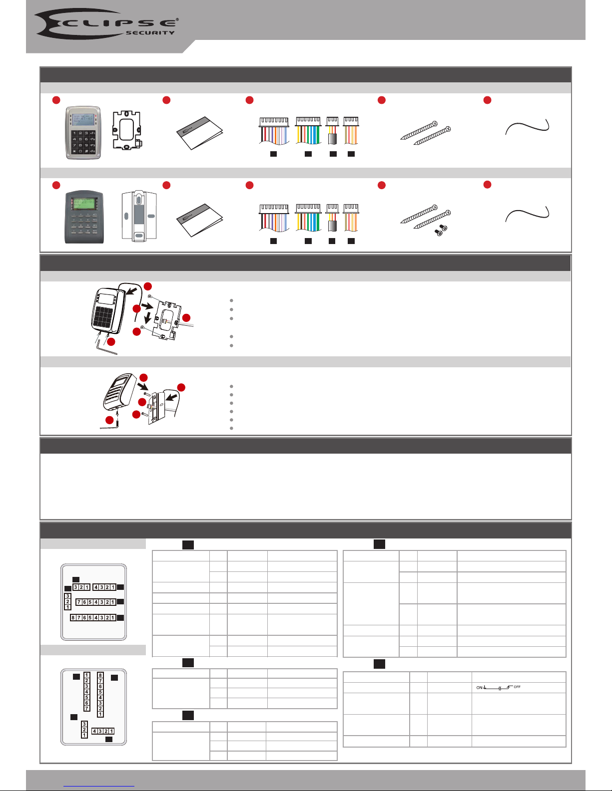
ACC970 [Touch-panel Metal Case]
ACC950
2
User Guide
2
User Guide
Installation
ACC970
ACC970
Pull the cables from the square hole of the mounting plate.
Use a screw to the mounting plate onto the wall.
Attach the water proof strip to the body, then connect the terminal cables to the body and attach the
body to the mounting plate.
Use the Allen key and screws (accessories supplied) to assemble the body onto the mounting plate.
Turn on the power, the LED will light and hear the beep sound, you will see "Ready"" on LCD board.
The communication wires and power line should NOT be bound in the same conduit or tubing.
Don’t equip reader and lock with the same power supply. The power for reader may be unstable when the lock is activating, that may make the
reader malfunction.
The standard installation: Lock relay and lock use the same power supply, and reader use independent power supply.
Use AWG 22-24 Shielded Twist Pair it sould avoid star wiring.
1.Tubing:
2.Wire selection:
3.Power supply:
4.F4: At rst time use, if appears no screen and green LED ashes, please press [F4] for 2 seconds.
Attach the water proof strip to the mounting plate.
Pull the cables from the square hole of the mounting plate.
Use a screwdriver to screw the base onto the wall.
Connect the terminal cables to the body and attach the body to the mounting plate.
Assemble the covers with the Allen key and screws (accessories supplied).
Turn on the power, the LED will light and hear the beep sound, you will see "Ready"" on LCD board.
ACC950
ACC950
1
Products
1
Products
3
Terminal Cables
3
Terminal Cables
4
Tools
4
Tools
5
Water proof Strip
5
Water proof Strip
Notice
Connector Table
Wire Application
Door Relay
Common-COM-Point
Door contact
Exit Switch
Alarm Relay
Power
Wire Application
Tamper Switch
Wire Application
Networking
Wiegand
Buzzer
LED
Wire Application
Arming Setting Input
Serial Port
Arming Status
indication (light)
Card existing indication
Description
(N.O.)DC24V1Amp
(N.C.)DC24V1Amp
(COM)DC24V1Amp
Negative Trigger Input
Negative Trigger Input
N.O./N.C. Options
(by jumper)
DC 12V
DC 0V
Description
N.C.
COM
N.O.
Description
RS-485 (B-)
RS-485 (A+)
WG DAT: 1 Inpu
ABA Data Input
WG DAT: 0 Input
ABA Clock Input
Buzzer Output 5V/100mA, MAX
LED Green Output 5V/20mA, MAX
LED Red Output 5V/20mA, MAX
Description
Latch type
Serial output (Transistor open
collector) (4800, N,8,1)
Arming output (Active low)/
Security trigger signa Output
Output LOW when card present
Color
Blue White
Purple White
White
Orange
Purple
Gray
Thick Red
Thick Black
Color
Red
Orange
Yellow
Color
Thick Green
Thick Blue
Blue
Green
Pink
Brown
Yellow
Color
Orange White
Yellow White
Red White
Brown White
Pin
1
2
3
4
5
6
7
8
Pin
1
2
3
Pin
1
2
3
4
5
6
7
Pin
1
2
3
4
P1Cable:
Cable:
Cable:
Cable:
P3
P2
P4
Wire Application
3-PIN Connector
Pin
1
2
3
Color
Black
White
Purple
Description
GND.
DC 12V
Security trigger signa Output
(Optional: apply to ACC970)
Cable:
P5
V110519
WG 1
WG 0
BZ
GLED
RLED
12V
GND
1
2
3
4
5
6
7
8
1
2
3
4
5
6
7
WG 1
WG 0
BZ
GLED
RLED
GND
12V
12V
GND
P2
P1
B-
A+
B-
A+
B-
A+
Host
CH1
CH2
1
2
3
4
5
6
7
1
2
3
4
5
6
7
B-
A+
Host
GND
12V
A+
B-
B-
A+
B-
A+
P2 P2
1
2
3
4
5
6
7
8
12V
GND
12V
GND
12V
GND
12V
GND
12V
GND
N.O.
N.O.
N.C.
COM
PB
12V
GND
P1
1
2
3
4
5
6
7
8
12V
GND
12V
GND
12V
GND
N.O.
N.C.
N.O.
COM
PB
12V
GND
P1
1
2
3
4
5
6
7
8
COM
Door contact
ALM
12V
GND
12V
GND
12V
GND
12V
GND
P1
1
2
3
4
5
6
7
8
4 3 2 1
N.C.
N.O.
COM
CTL
12V
GND
PB
P1
P4
12V
GND
ARM
LCD Access Controller
Metal Case / Standard
ACC970 ACC950
Connect to Electric Bolt or Magnet Lock
Electric Bolt
Electric Bolt
Magnetic Lock
Controller
※
Security trigger signal: Please refer to the "Operation".
Controller
Connect to strengthen security with ACC899
Connect to Reader
Electric Strike
Alarm
Controller
Controller Reader
Controller
ACC1000
ACC1000
Converter
Node ID 001
Node ID 254
Door No. 1
Door No. 9
Door No. 8
Door No. 16
Request To ExitRequest To Exit
Request To Exit
Door Contact
POWER
12VD C
POWER
12VD C
POWER
12VD C
POWER
12VD C
POWER
12VD C
Connect to Door Contact
Controller
Controller
Controller
Controller
POWER
12VD C
Connect to Networking
POWER
12VD C
POWER
12VD C
POWER
12VD C
POWER
12VD C
Connect to Electric Strike
Wiring Diagram
Front Panel & Indicator
18/02 FRI Duty:0
18/02 FRI Duty:0
10:49:34
10:49:34
Ready......
Ready......
Data
Week
Work Status
Data
Week
Work Shift Status
Arm ing Set ting Input
Indicator (Green)
Card Present (Green)
Error OK
Arming Setting Input Indicator (Red)
Card Present (Green)
Operate Correct/Stand-by(Green)
Operate Error (Red)
Arming (Green)
Alarm (Red)
Host Receive (Green)
Host Transmit (Red)
Esc/Quit
Up
Down
Left
Right
Enter/OK
Arming(Green)
Alarm(Red)
RX TX
Esc/Quit
Up
Down
Left
Right
Enter/OK
F1
F2
F3
F4
Press 1 time
Duty on
Duty off
Overtime on
Overtime off
Press 2 time
Break out
Break RTN
Out
Return
Attendance

ACC950 / ACC970
V110519
A 18/02 15:45:25
FRI 00001 001
B. Enter/Escape Program Mode
C. Initial Setup
D. Security Trigger Signal
Enter program mode
Input 123456 or PPPPPP (PPPPPP= modied Master Code; Default= 123456)
[e.g.] If the Master Code= 876112, input
87 6112
→ E
nter program mode
※
If without any operation for 30 seconds access controller will escape program mode.
Escape program mode
Press continuously
→
Quit
6
6 8
8
[e.g.] ACC970 is the 8th slave reader under the 16th ACC1000.
Door-H input (door NO. of controller); Door-L input (door No. of the reader).
[e.g.] ACC950 is a controller and its Node ID is 8.
Door-H input ; Door-L input
1
8
Changing the Node ID of Reader
Enter program mode
→
Parameters[1]
→
Node ID
→
Input New Node ID:1~254(default value: 001)
→
Input: 1~4 to Show Card ID format? (1.No, 2.WG, 3.ABA, 4.HEX) → Input Door number H: 1~254(door
No. of its controllen) → Input Door number L: 1~254(door No. of reader) → Succeeded
3 1
Work Status Code
Date
Time
Serial NO.
User Add.
Week
A: Duty On
B: Duty Off
C: Overtime On
D: Overtime Off
E: Break Out
F: Break RTN
G: Out
H: Return
01: PWD/PIN Error
03: Invalid Card
04: Time-zone Error
11: Normal Access
16: Egress (Request to exit)
17: Alarm
31: Anti-pass back Error
Work Status Code:
Changing the Master Code
Enter program mode
→
Too ls
→
Master Code
→
Input the 6-digit new master code
→
Succeeded
5 2
Restoring Factory Settings
Enter program mode
→
Parameters[2]
→
Factory Reset
→
select [1: Yes] → Succeeded...
4 9
Enable the Security Trigger signal
Enter program mode
→
Parameters[1]
→
Arming Pulse
→
Input [10](default value:1000) → become the Security Trigger signal Output
※
If Request To Exit connect to [ACC899], the Request To Exit can control the lock immediate.
3 9
Review the old events
Enter program mode
→
Too ls
→
View Events
→
the display will show the history events.
5 0
Changing the Language
Enter program mode
→
Too ls
→
Language
→
EN → Succeeded...
5 1 1
Adding and Deleting Card
Operation
A. Keyboard Lock/ Unlock
Lock/ Unlock
Hold down and buttons in simultaneously to lock/unlock the keyboard.
Mode4/Mode8
1
Enter program mode
→
Add/Delete
→
Add Card > ID
→
Input 5 -digit user address
→
Input Site Code
→
Input Card Code
1
Adding Card by Card ID
1 5
Enter program mode
→
Add/Delete
→
Delete > Address
→
Input Start address
→
Input End address
Deleteing User Address
2 1
Enter program mode
→
User Setting
→
Password
→
Input 5 -digit user address
→
Key in 4-digit PIN
Setting up the password
2 2
Enter program mode
→
User Setting
→
Access Mode
→
Input 5 -digit user address
→
1: Card; 2: or PIN; 3: & PIN; 4: Pause;
Setting up the access mode
Mode6
※
In Mode6, user address is card code. Only suspend or recover to add or delete the cards.
Tag Information
SITE CODE
CARD COD E
SITE CODE
CARD COD E
1 2
Enter program mode
→
Add/Delete
→
Add > RF Learn
→
Input 5 -digit user address
→
Input Tag Units(pcs)
→
Close Tag into RF Area to induct.
Adding Card RF Iduction
※
For block Sequential cards, present the lowest card code card to the controller reader; for block
random cards, present all the cards one by one to the controller reader.
71
Enter program mode
→
Add/Delete
→
Recover > Address
→
Input Start address
→
Input End address
Adding Card
※
For block Sequential cards, present the lowest card code card to the controller reader; for block random cards, present all the cards one by one to
the controller reader.
1 3
3 8
Enter program mode
→
Parameters[1]
→
Arming PWD
→
Input: 0000
Card Only
3 8
Enter program mode
→
Parameters[1]
→
Arming PWD
→
Key in 4-digit PIN [0001~9999, default value: 1234]
Card and PIN
4 8
Enter program mode
→
Parameters[2]
→
Duress Code
→
Key in 4-digit PIN [0001~9999, default value: 4321]
Card or PIN
Enter program mode
→
Add/Delete
→
Suspend > Address
→
Input Start address
→
Input End address
Deleting Card
※
M6 access mode setting procedure is the same as the arming password/duress code setting procedure in M4.
※
First Update the Firware to 7v4_T2 later
V110519
LCD Access Controller
Metal Case / Standard
Enter program mode
→
Add/Delete
→
Antipass Group
→
Input Start address
→
Input End address
→
1: Yes; 2: No;(select one)
1 9
Card set- up
Usually, anti-pass back is commonly applied to parking lots in order to prevent from multi-entry with one card, requires to set bith card and device
as the owings:
F. Anti-Pass Back(M4/M8 only)
Device set-up
Enter program mode
→
Parameters[2]
→
Anti-pass back
→
1: Yes; 2: No;(select one)
→
1: In; 2: Out;(select one)
4 7
G. Lift Control
Connect with ACC1040 to control which oors the user will be able to access.
Set
Floor
1
0
17
0
9
0
25
0
1
2
3
0
19
0
11
0
27
0
2
0
18
0
10
0
26
0
4
0
20
0
12
0
28
0
5
0
21
0
13
0
29
0
6
0
22
0
14
0
30
0
7
0
23
0
15
0
31
0
8
1
24
0
16
1
32
0
Enter program mode
→
Too ls
→
Termingal Port
→ 1:
ACC104 0
5 4
Setting Lift control
Enter program mode
→
User Setting
→
Single Floor
→
Input 5 -digit user address
→
Input single oor number: 1~32
2 4
Single oor set-up
Enter program mode
→
User Setting
→
Single Floor
→
Input 5 -digit user address
→
Select range: 1 or 2
→
Input 16 digits multi oors
number [0:disable, 1: enable]
[e.g.] Set NO. 114, to access the 8th and the 16th oors.
Enter program mode
→
User Setting
→
Single Floor
→
114
→
1
→
0000000100000001
2
2
5
5
Multi oors set- up
H.Arming Mode
Conditions:
1.Arming is enabled
2.Alarm system connected
Application:
1. Door lef t open warnings: these are generated when the door is held open for longer than the lock relay time and door
open time.
2. Force o pen (Unauthorized access alarms): these are generated when a door is opened without a valid c ard being
presented or a request to exit signal being received.
3. Door contac t error : when the c ontroller in arming status and power failure, reset power may activate alarm system.
Manu Tree
5. Tools
1. Language
2. Master Code
3. Master Range
4. Terminal Port
5. ACC1040 Node
6. Open Time Zone
7. Information
8. Clock Setting
9. Control Mode
0. View Events
6. Quit
7. Quit & Arming
4. Parameters[2]
1. Auto Relock
2. Egress(R.T.E)
3. Attendance
4. Master Node
5. Force Open
6. Close & Stop
7. Anti-pass-back
8. Duress Code
9. Factory Reset
0. Key (#) is Bell
3. Parameters[1]
1. Node ID
2. Auto open Zone
3. Door Relay Tm
4. Door Close Tm
5. Alarm Relay Tm
6. Alarm Delay Tm
7. Arming Delay Tm
8. Arming PWD
9. Arming Pulse
0. Auto Alarm Tm
2. User Settings
1. Password
2. Access Mode
3.Extend Options
4. Single Floor
5.Multi Floor
1. Add/ Delete
1. Add Card >ID
2. Add > RF Learn
3. Suspend > Address
4. Suspend > ID #
5. Delete > Address
6. Delete > ID #
7. Recover > Address
8. Recover > ID #
9. Antipass Group
Enter program mode
→
Too ls
→
Control Mode
→
1:M4, 2:M6, 3:M8 (refer to following table) → Succeeded
5 9
E.Control Mode (M4/M6/M8)
※
The users up to 65,535 in Mode 6, since it reads CARD CODE(5 digits) only, unlike that Mode4/Mode8 read SITE CODE and CARD CODE(10 digits).
Mode
Networking/
Standalone
Standalone
Networking/
Standalone
Networking/
Standalone
User
Capacity
Access Mode
M4
M6
M8
Yes
No
Yes
Yes
No
Yes
Yes
No
Yes
Yes
No
Yes
32
No
32
11
No
11
1,200
(950)
1,500
(970)
No
1,200
(950)
1,500
(970)
1,024
(950)
3,000
(970)
65,535
1,024
(950)
3,000
(970)
Auto- show
Duty time
Event log
Capacity
120
Holidays
Anti
force
Time
Zone
Lift
Control
Anti-pass
back
1.Card only
2.Card and PIN
(4-di git PIN)
3.Card or User address
(5-digit)
+ Individual PIN
(4-di git indiv idual PIN )
1.Card only
2.Card and PIN
(4-di git public PIN= A rming PWD)
3.Card or PIN
(4-di git public PIN= D uress code)
1.Card only
2.Card and PIN
(4-digit individual PIN)
3.Card or PIN
(4-di git indiv idual PIN )
7
Enter program mode
→
Quit
6
Enable/Disable Arming Mode:
Enable Arming Mode
Disable Arming Mode
Program Mode
Door Open
Door Close
Access Mode → Input 4 digit arming code
→
→
Input 4 digit arming code
→
Present the card to the controller reader
→
Input 4 digit arming code
→
Present the card to the controller reader
Access Mode → Input 4 digit arming code
→
Enter program mode → Quit & Arming
 Loading...