

®
Guided Wave Radar
Level Transmitter
Installation and Operating Manual
™
705
software V3.x
2
UNPACKING
Unpack the instrument carefully. Make sure all components
h
ave been removed from the foam protection. Inspect all
components for damage. Report any concealed damage to
the carrier within 24 hours. Check the contents of the carton/crates against the packing slip and report any discrepancies to Magnetrol. Check the nameplate model number
to be sure it agrees with the packing slip and purchase
order. Check and record the serial number for future reference when ordering parts. To avoid moisture ingress in the
housing, covers should be fully tightened at all times. For
t
he same reason, plugs should remain properly installed in
the cable entries until replaced with a cable gland.
SPECIAL CONDITIONS FOR ATEX INTRINSICALLY SAFE USE
These units are in conformity with the
provisions of:
1. The EMC Directive: 2014/30/EU.
T
he units have been tested to EN
61326: 1997 + A1 + A2.
2. Directive 2014/34/EU for Equipment or protective system for use in potentially explosive atmospheres. ECt
ype examination certificate number KEMA99ATEX0518X
(intrinsic safe units) or BKI 12 ATEX 0017 (Ex d units) or
KEMA99ATEX5014 (Non sparking units).
3. The PED directive 2014/68/EU (pressure equipment
directive). Safety accessories per category IV module
H1.
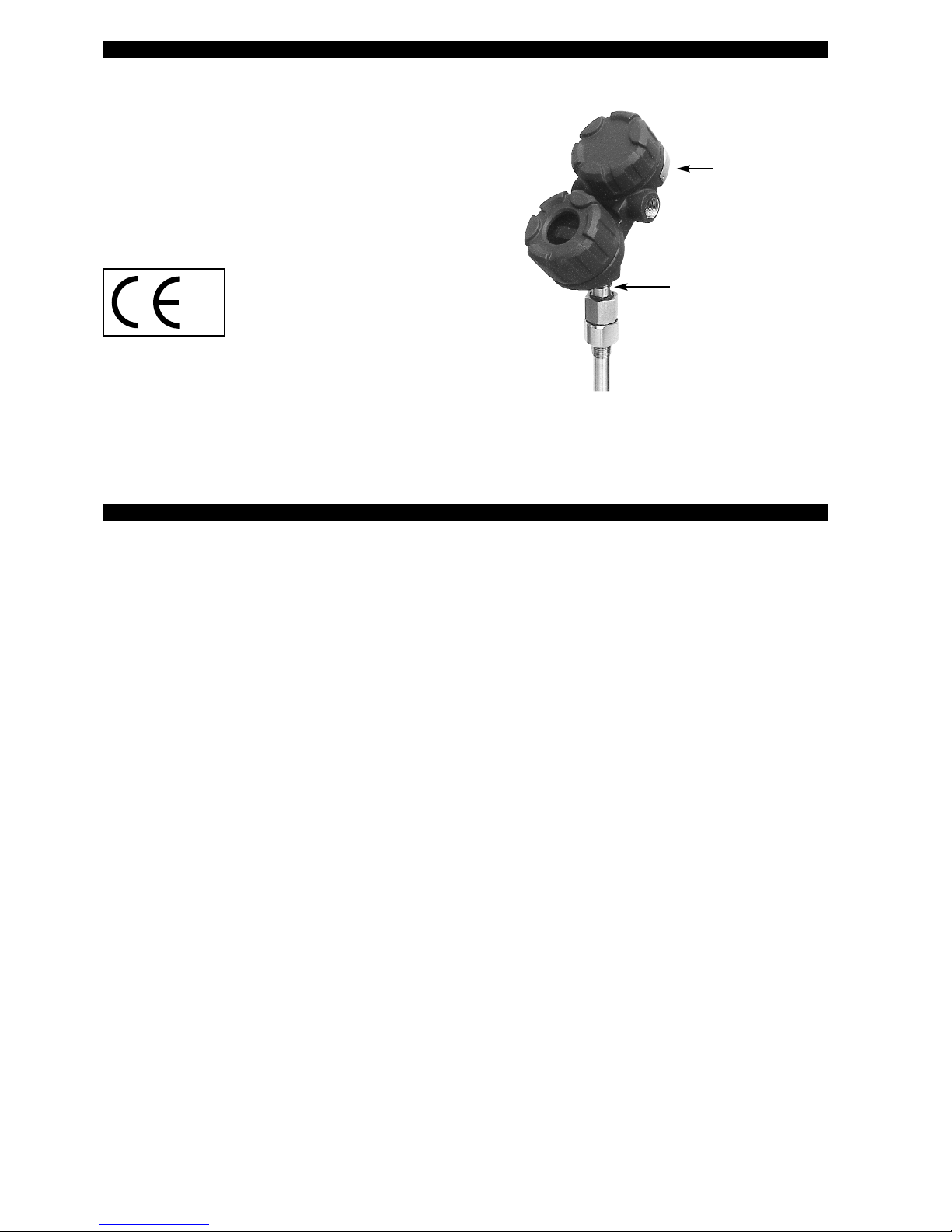
Amplifier nameplate:
-
partnumber
- amplifier
- serial n°
-
temperature/pressure
- approval data
Probe nameplate
- partnumber
-
serial number
0
038
0
344
Because the enclosure of the Guided Wave Radar Level Transmitter Eclipse Model 705-5xxx-x1x and 705-5xxx-x7x and/or
Probe Eclipse Model 7xx-xxx-xxx is made of aluminium, if it is mounted in an area where the use of category 1G apparatus is
required, it must be installed such, that, even in the event of rare incidents, ignition sources due to impact and friction sparks
are excluded.
For applications in explosive atmospheres caused by combustible dust, gases, vapours or mists and where category 1G or 1D
apparatus is required, electrostatic charges on the non-metallic parts of the Probe Eclipse Model 7M5-xxx-xxx, Model 7M7-xxxxxx and Model 7xF-xxx-xxx shall be avoided.
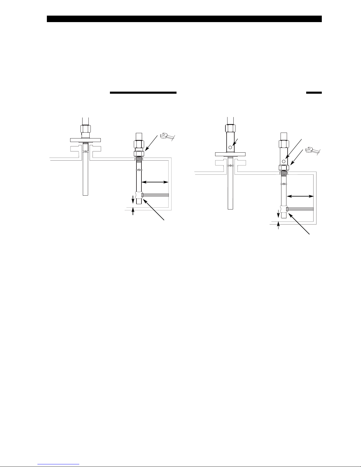
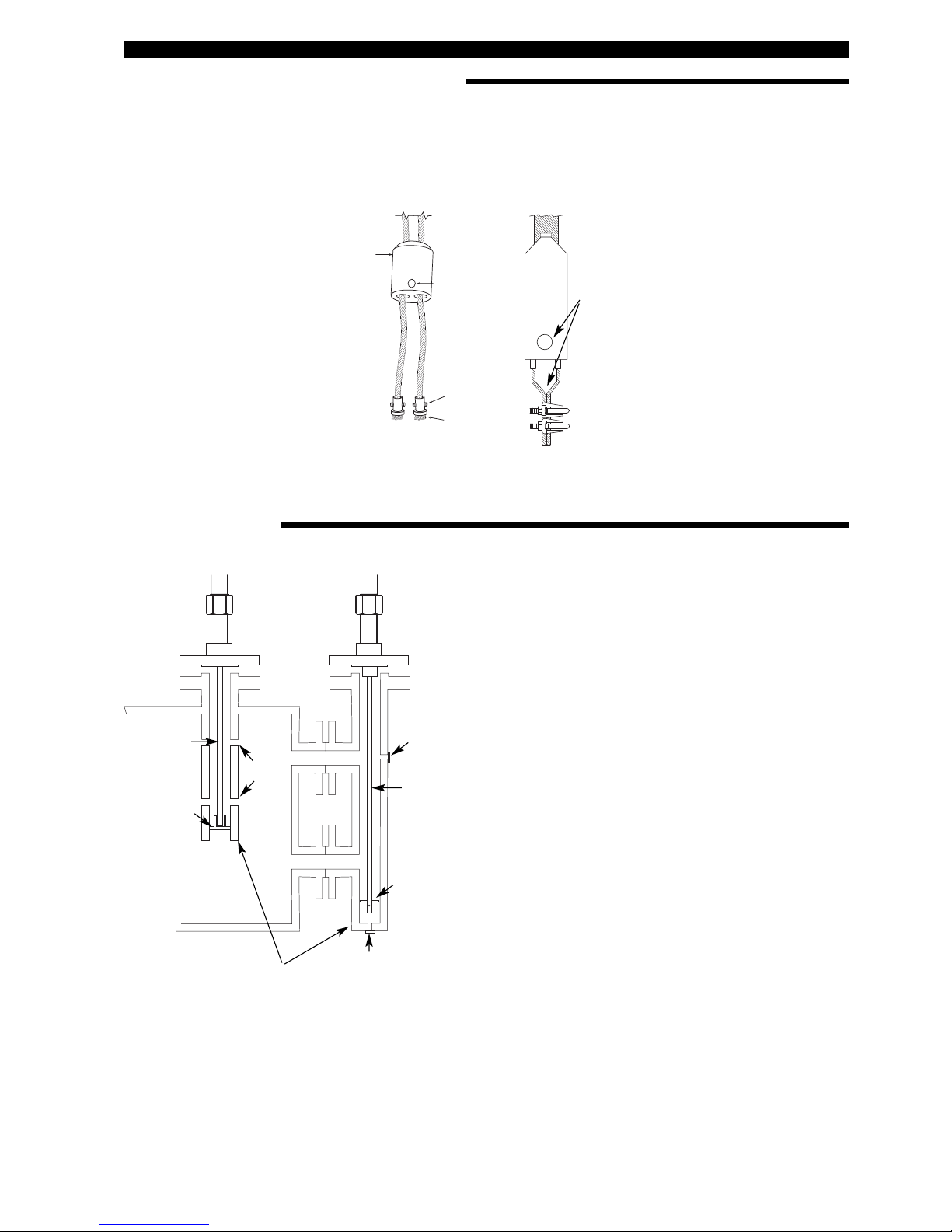
S
ize: 38 mm
(
1 1/2") or
a
djustable
w
rench
Customer supplied brackets are recommended
per each 3 m length. (Required for WGH § 19
i
nstallations.)
Not important
min 25 mm (1")
from tank bottom
3
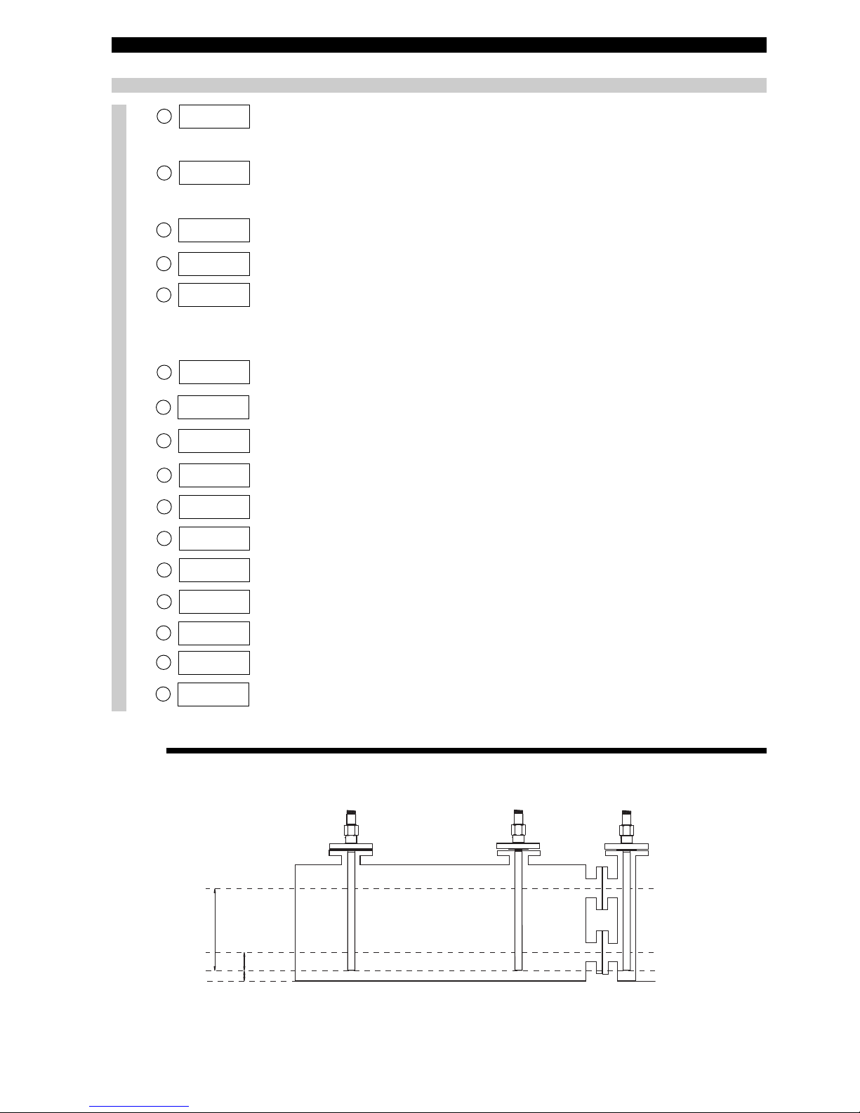
Overfill safe and Overfill proof
Eclipse 7MD/7ML, 7MR/7MM and 7MT/7MN coaxial GWR
probes are “Overfill safe” in use and “Overfill proof” certified.
Overfill safe means that the unit is capable to measure up
to the process connection.
Overfill proof protection (such as WHG or VLAREM) certifies reliable operation when the transmitter is used as
overfill alarm but assumes that the installation is designed
in such way that the vessel/ cage cannot overfill.
Eclipse 7MQ/7MS has a transitioning zone (zone in which
the unit does not measure accurately) at the top. Maximum
level should not be higher than 25 mm (1") up to 200 mm
(8") (depending dielectrics - see probe specifications) below
the process connection. This may include utilizing a nozzle
or spool piece.
Note: When using the 7MQ or 7MS probe, keep transmitter
and probe matched as a set.
Metallic (or any conductive) obstructions in the tanks
Metallic obstructions have no influence on the measuring
performance of coaxial GWR probes.
Turbulence
Customer supplied mounting brackets are recommended
per each 3 m (10’) length and have no influence on the measuring performance of coaxial GWR probes.
Stillwell /cages
Coaxial GWR probes are ideally suited for use in stillwells
or cages. There is no min. clearance allowance to be taken
into consideration.
Shortening of probe length
Coaxial GWR probes can be easily shortened on site when
a procedure for this is strictly followed. This procedure can
be separately obtained from factory.
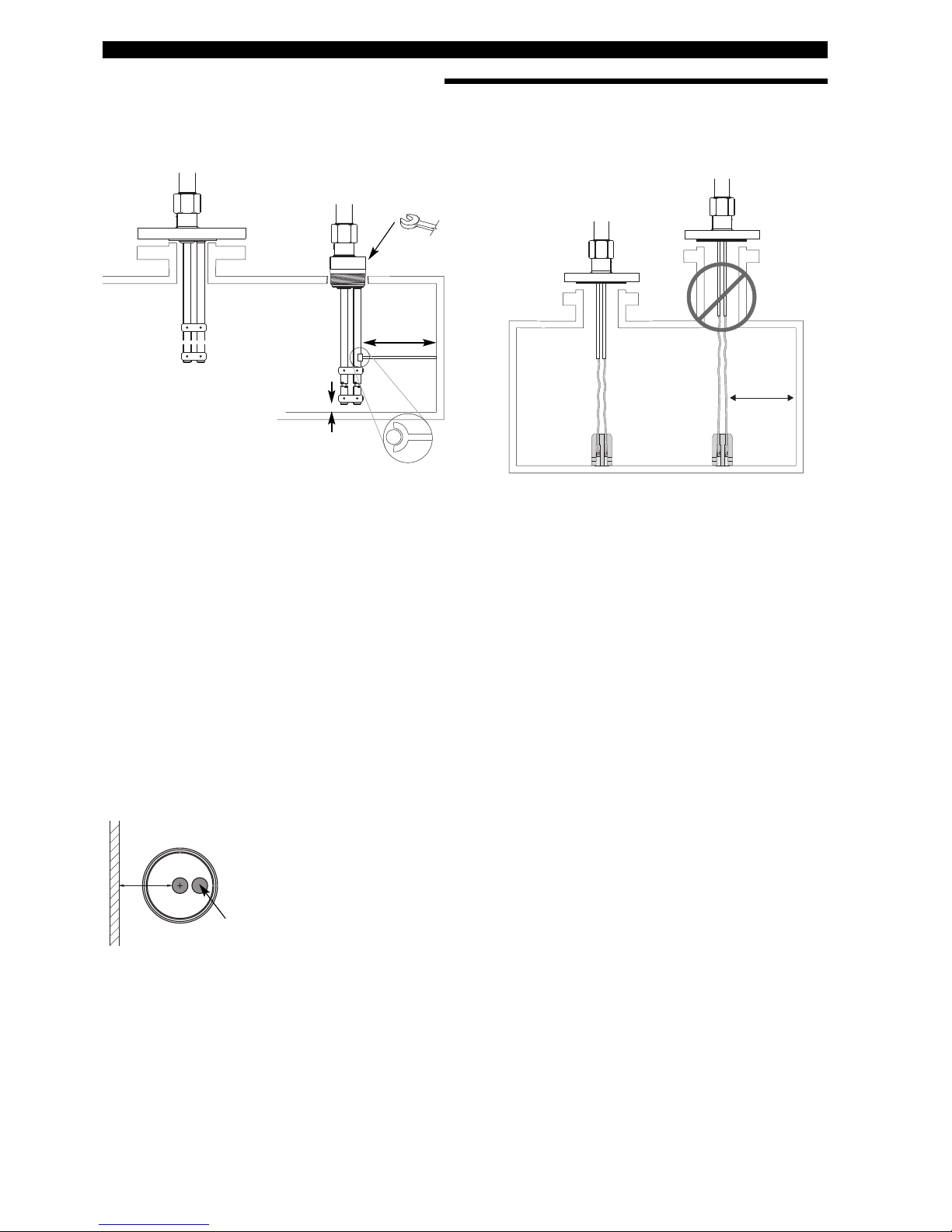
Size: 38 mm
(1 1/2") or
adjustable
wrench
1/4" NPT
plugged
flushing
connection
1
/4" NPT
p
lugged
fl
ushing
c
onnection
Customer supplied brackets are recommended
p
er each 3 m length. (Required for WGH § 19
installations.)
Not important
min 25 mm (1")
f
rom tank bottom
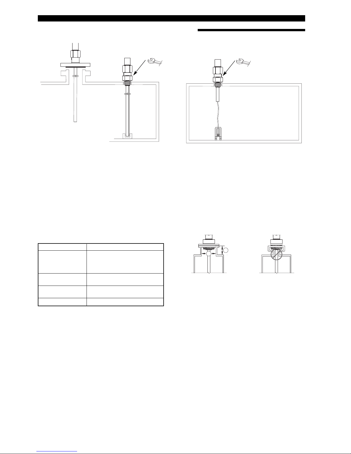
MOUNTING
C
oaxial type GWR probes
(7MD - 7MQ - 7MR - 7MS - 7MT)
Note: The flushing connection allows to purge the inside of
the coaxial probe without dismantling. Re-assure the use of
compatible purging liquid/gas to avoid unwanted chemical
reaction.
C
oaxial type GWR probes: Flushing connection
(7ML - 7MM - 7MN)
IMPORTANT:
To avoid damaging during transportation, Eclipse
®
7MD/7ML large coax probes are shipped with 3 transport screws, securing
the inner antenna. The 3 screws have to be removed prior to installation. They are located nearby the process connection. A
separate label is attached to draw the attention to remove the screws.
To avoid moisture ingress in the housing, covers should be fully tightened at all times. For the same reason, cable gland and
plugs should be properly installed in the cable entries.
The unit is preconfigured from factory, based on given application details (when available). Therefore transmitter and GWR
probe have the same serial n°.
Please make sure that corresponding serial numbers are mounted together.
4
MOUNTING
Overfill safe and Overfill proof
Eclipse twin rod GWR probes use software to ignore level
readings in the transitioning zone at the top of the GWR
probe. The maximum level is a minimum of 150 mm (6")
below the process connection. This may include utilizing a
nozzle or spool piece to raise the probe. Twin rod probes
are overfill proof certified but not overfill safe in use.
Eclipse twin cable GWR probes, used in media with low
dielectrics (hydrocarbons, powders) may require the setting
of a blocking distance (zone in which the unit will not measure) of 300 mm up to 500 mm (12" to 20") depending probe
length. The longer the probe, the longer the blocking distance will be. Eclipse twin cable GWR probes are not overfill proof certified and not overfill safe in use.
Metallic (or any conductive) obstructions in the tanks
Objects in the proximity within 25 mm (1") or closer such as
pipes, support beams, metal ladders etc… may cause erroneous readings.
Turbulence
7MB: Customer supplied brackets are recommended per
each 3 m (10') length and have no influence on the measuring performance of 7MB GWR probes. Use the “off center” rod to fasten the brackets (see above drawings).
7M5/7M7: It is recommended to secure the probe if significant turbulence exists. Optional weights are available to
keep the probe taught. The probe should not make any contact with the metal tank wall. The 7M7 (liquids) probe can be
attached to the bottom of the tank – it is not recommended
to attach the 7M5 (solids) probe at the bottom of the tank.
Stillwell/cages
Min. 3" / DN 80 size nozzles, stillwells or by-pass cages are
required for a good operation. Twin rod/cable probes should
be min 25 mm (1") away from any metal tank wall. 7M5/7M7
have a 76 mm (3") inactive section. For nozzles < 3"/
DN 80, this section should be flush with the bottom of the
nozzle or extend into the vessel.
IMPORTANT:
Twin rod/cable probes should be installed into a metal tank,
stillwell or by-pass cage to meet CE requirements
(EN 61326: 1997 + A1 + A2) electromagnetic compatibility.
Tank or cage wall
Off center rod
min 25
(1)
Size: 47 mm
(1 7/8") or
adjustable
wrench
min. 25 mm (1")
from any metal
object
m
in 25 mm (1")
from tank bottom
Use half open brackets
f
or twin rod probes.
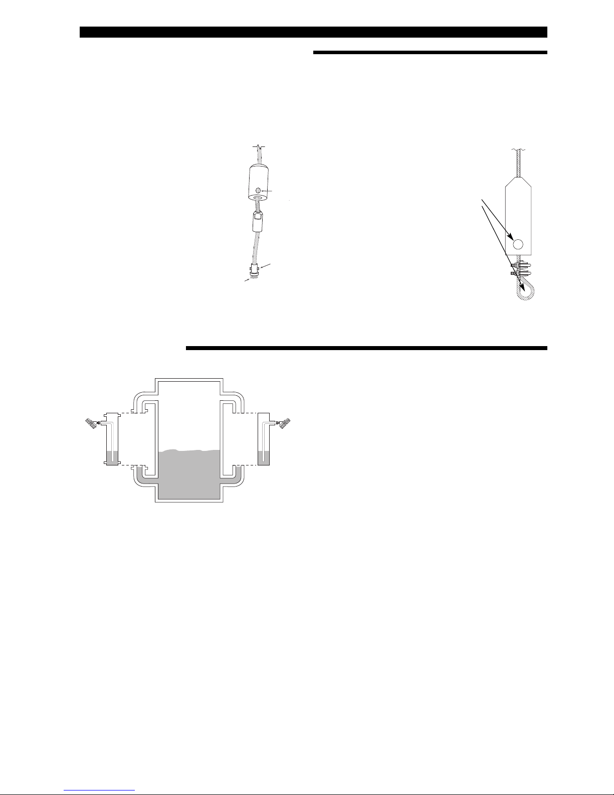
Twin rod (7MB) / Twin cable (7M5 - 7M7) GWR probes
For twin cable:
min 25 mm
(1") from any
metal object
M
ounting considerations for 7MB
Nozzle should be DN80 (3") diameter or larger.
Mounting considerations for 7M5/7M7
For nozzles < DN80 (3") diameter, the bottom of the inactive section of the probe should be flush with the bottom of
the nozzle or extend into the vessel.
5
MOUNTING
1
3 mm Ø
(
0.50")
1
3
2
4
7M7/7M5 probe can be shortened
in field.
a.raise the weight (1) to expose the two
securing devices (2)
b.loosen the two #10-32 set screws (3)
on both securing devices using a
2.5 mm (3/32") hex wrench and slide
the securing devices off of the probe
c. slide the TFE weight off of the probe.
d.cut and remove the required cable (4)
l
ength
e.remove 90 mm (3 1/2") of the rib
between the two cables
f. strip 16 mm (5/8") of coating from the
two cables.
g.slide the TFE weight back on to the
probe.
h.enter new probe length (cm or inches)
in software (See page 12, Item 9)
Note: Probe can be attached to the tank
b
ottom using the noose or the 13 mm Ø
(0.50") hole provided in the TFE weight.
7M7 GWR probes: cable tension should
not exceed 89 N
7M5 GWR probes: pull down force should
not exceed 1360 kg (3000 lbs)
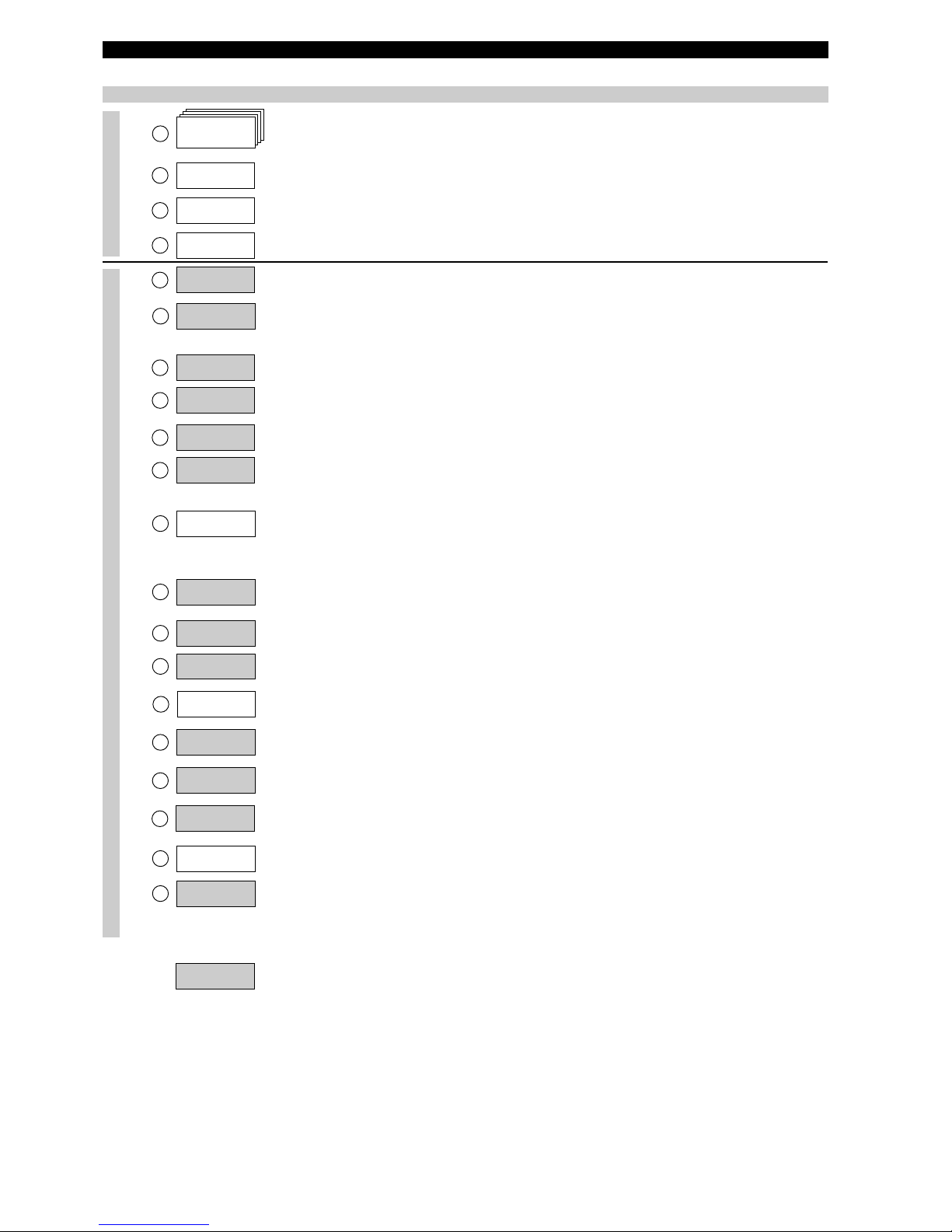
Twin rod (7MB) / Twin cable (7M5 - 7M7) GWR probes
Cage GWR probe (7MG)
Shortening of probe length
7MB probes can be shortened safely in the field. Make sure to re-install the bottom spacer for proper alignment and to adapt
t
he probe length/ 4-20 mA settings in the menu.
Twin cable probes can be safely shortened in the field using below procedure. Make sure to adapt the probe length / 4-20 mA
settings in the menu.
Vent
Drain
Customer or magnetrol
supplied cage/bridle or still well.
Venting
holes
Bottom spacer
Bottom spacer
For cage/still well:
2": Ø 13 mm
(0.50") rod
For cage/still wells:
3": Ø 19 mm (0.75") tubing
4": Ø 25 mm (1.00") tubing
Overfill safe
All 7MG GWR probes are overfill safe. Overfill safe means
that the impedance match of the waveguide (probe) is
aligned from electronics down to the bottom of the GWR
probe. This allows the Eclipse 705 to measure up to the process flange without any dead zone at the top of the GWR
probe.
Metallic (or any conductive) obstructions in the tanks
Metallic obstructions have no influence on the measuring
performance of cage GWR probes.
Stillwell/cages
The cage GWR probe is a single rod GWR probe which
uses an existing or new cage, bridle or schedule pipe stillwell to re-create the same propagation of signal of a coaxial GWR probe. Cage GWR probes are suited for 2", 3" or 4"
size diam. and use an impedance matching part that aligns
in the same way with the characteristic impedance of a
standard coaxial style GWR probe.
Shortening of probe length
Cage GWR probes can be easily shortened on site. Always
re-install the bottom spacer and adapt the new probe length
in the menu of the amplifier.
6
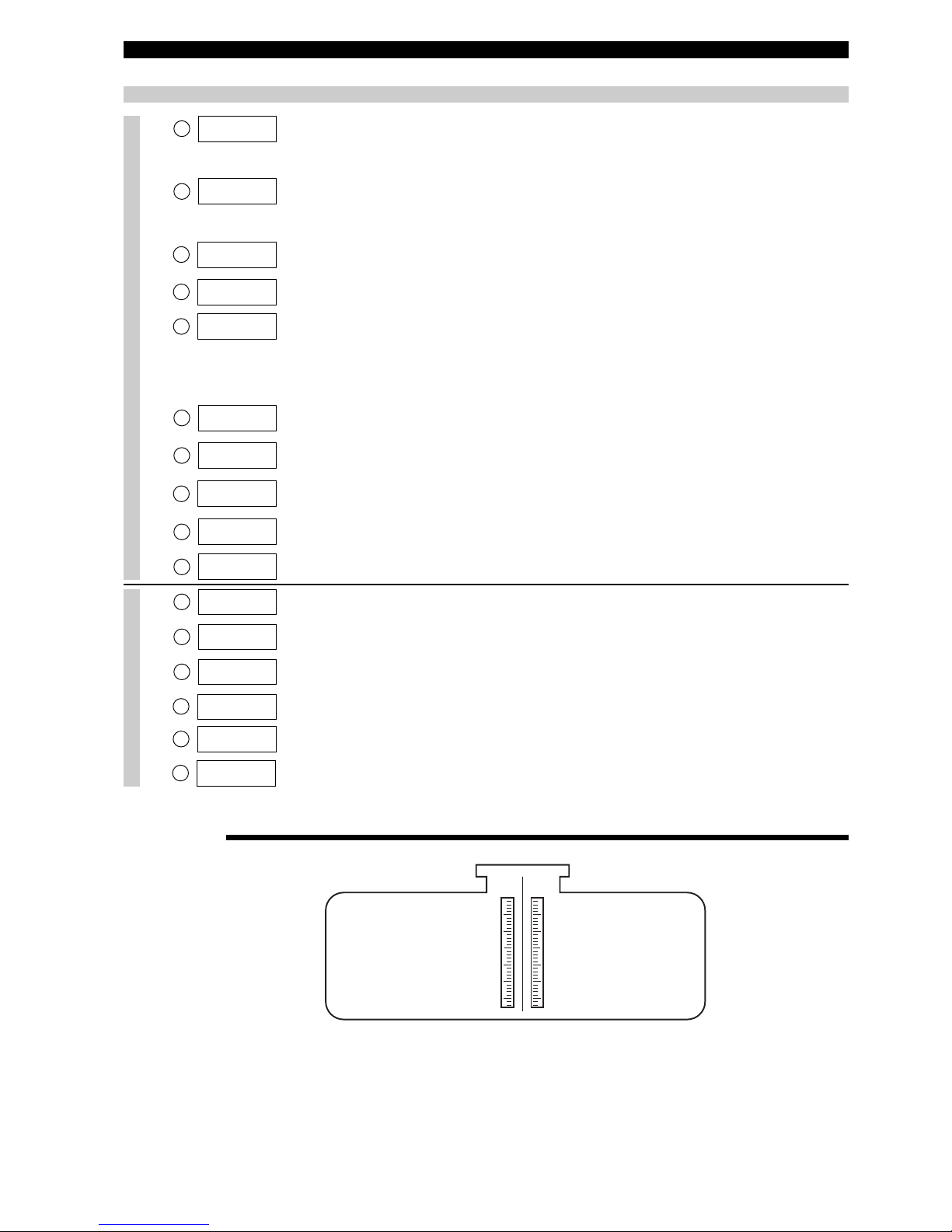
MOUNTING
Single rod (7MF - 7MH - 7MJ) / Single cable (7M1 - 7M2) GWR probes
Size: 38 mm
(1 1/2") or
adjustable
wrench
Size: 38 mm
(1 1/2") or
adjustable
wrench
High Level shutdown and Overfill protection
Special consideration is necessary in any high level shutdown / overfill protection application where single rod GWR
probes are used. To ensure proper measurement, the guided wave radar probe should be installed so the maximum
overfill level is at a minimum of 120 mm (4.8") up to
910 mm (36") – blocking distance depending application
below the process connection. Consult factory for further
information.
Metallic (or any conductive) obstructions in the tanks
Objects in the proximity of the probe may cause erroneous
readings.
Turbulence
The bottom of the probe should be stabilized if turbulence
will cause a deflection of more than 75 mm at 3 m (3" at 10')
of length. Optional bottom spacers in TFE (for 7MF) or
PEEK (for 7MJ) should be used to stabilize the probe, in
case turbulence exists. It is recommended to secure the
probe (7M1/7M2) if significant turbulence exists (see above
drawing at right side). Optional weights are available to
keep the probe taught. The 7M1 (liquids) probe can be
attached to the bottom of the tank – it is not recommended
to attach the 7M2 (solids) probe at the bottom of the tank.
The probe should not make any contact with the metal tank
wall.
Stillwell/cages
Max. 6” / DN 150 size stillwells or by-pass cages or a metal
tank wall within 150 mm (6”) of the probe, will allow the unit
to measure accurately in media with dielectrics down to
ε
r
1,9.
Nozzles do not restrict the performance by ensuring the following:
1. Nozzle must be 50 mm (2") or larger diameter.
2. Nozzle inside diameter (A) should be ≥ to nozzle height
(B). If this is not the case, it is recommended to adjust
BLOCKING DISTANCE and/or SENSITIVITY settings.
IMPORTANT:
Single rod/cable probes should be installed into a metal
tank, stillwell or by-pass cage to meet CE requirements
(EN 61326: 1997 + A1 + A2) electromagnetic compatibility.
When used in a non-metallic vessel flange (metal) mounting
is recommended for optimal performance.
Distance to probe
Acceptable objects
< 150 mm (6") Continuous, smooth, parallel,
conductive surface (e.g. metal
tank wall);
probe should not touch
tank wall
> 150 mm (6") < 1"/DN25 diameter pipe and
beams, ladder rungs
> 300 mm (12") < 3"/DN80 diameter pipe and
beams, concrete walls
> 450 mm (18") All remaining objects
Pipe reducers
should not be used
Correct installation
A
B
7
MOUNTING
Shortening of probe length
Single rod/cable probes can be shortened safely in the field. Make sure to adapt the probe length/ 4-20 mA settings in the menu
and the re-install of a bottom spacer when applicable.
Single cable probes can be safely shortened in the field using below procedure. Make sure to adapt the probe length/ 4-20 mA
settings in the menu.
13 mm fl
(0.50")
1
2
3
4
7M1/7M2 probe can be shortened in
field.
a.raise TFE weight (1) exposing secur-
ing device (2)
b.loosen both #10-32 set screws (3)
using 2.5 mm (3/32") hex wrench
and remove securing device
c. cut and remove needed cable length
(4)
d
.re-attach securing device (2) and
tighten screws
e.enter new probe length (cm or inch-
es) in software (See page 12, Item 9)
13 mm Ø
(0.50")
Note: Probe can be attached to the tank
bottom using the noose or the 13 mm Ø
(0.50") hole provided in the TFE weight.
7M1 GWR probes: cable tension should
n
ot exceed 89 N (20 lbs).
7M2 GWR probes: pull down force
should not exceed 1360 kg (3000 lbs)
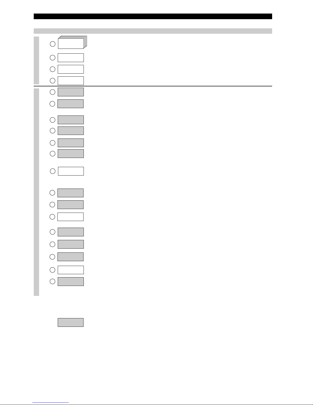
Single rod (7MF - 7MH - 7MJ) / Single cable GWR probes
Overfill safe and Overfill proof
Eclipse 7EK GWR probes are “Overfill safe” in use and
“Overfill proof” certified.
Overfill safe means that the unit is capable to measure up
to the process connection. Units with “non overfill safe”
probes use software to ignore level readings in the blocking distance or transitioning zone. When level rises too high
in this zone, the unit may consider the end of probe reflection as the real level and may report an empty vessel
instead of an overfilling vessel.
Overfill proof protection (such as WHG or VLAREM) certifies reliable operation when the transmitter is used as
overfill alarm but assumes that the installation is designed
in such way that the vessel/cage cannot overfill.
The 7EK probe is designed to replace without modification
top/bottom mounted displacer transmitters. The unit will
measure over the entire probe length and indicate for
20.5 mA above the highest measurable point and 3.8 below
the lowest measurable point.
Top/Bottom GWR probes
(7EK)
1 1/2" or 2"
socket weld or
NPT
1
1/2" or 2"
F
langed
8
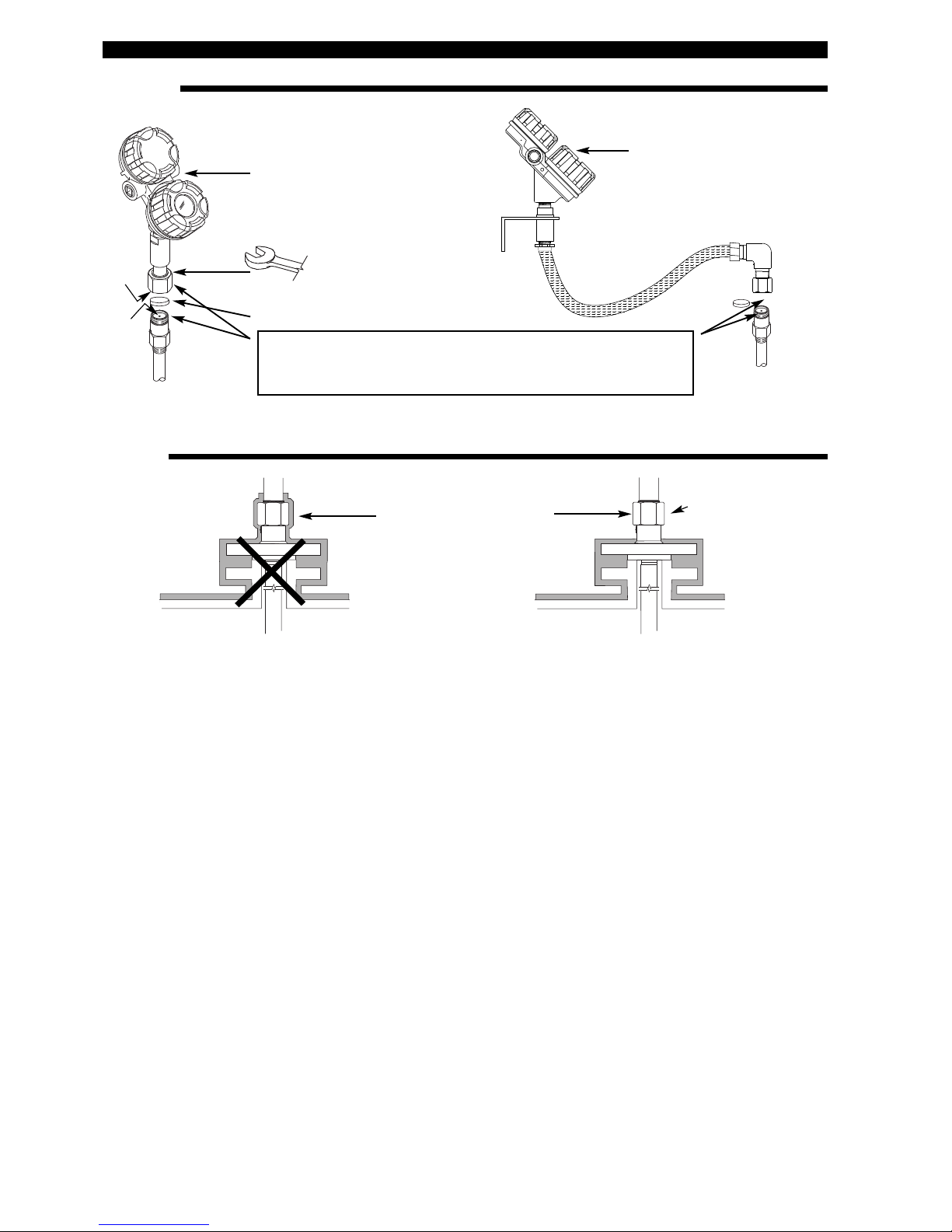
MOUNTING
Do not insulate the
high frequency connector
in case of high temperature
applications
Insulation
WRONG GOOD
M
ax +150 °C (+300 °F)
Max +100 °C (+212 °F) for Ex d unit
360° rotatable: Position for
optimum wiring/viewing
Max. rotation 270°
Size: 38 mm (1 1/2") or
adjustable wrench
Recommended torque 60 Nm
(45 ft-lbs)
Remove protection
Remove
protection
C
AUTION: be careful not to bend or dirty the gold, high frequency
male connector (a) and its female connector (b). Clean with isopropyl alcohol and cotton swabs, if necessary
(a)
(b)
Transmitter
Integral
Remote
9
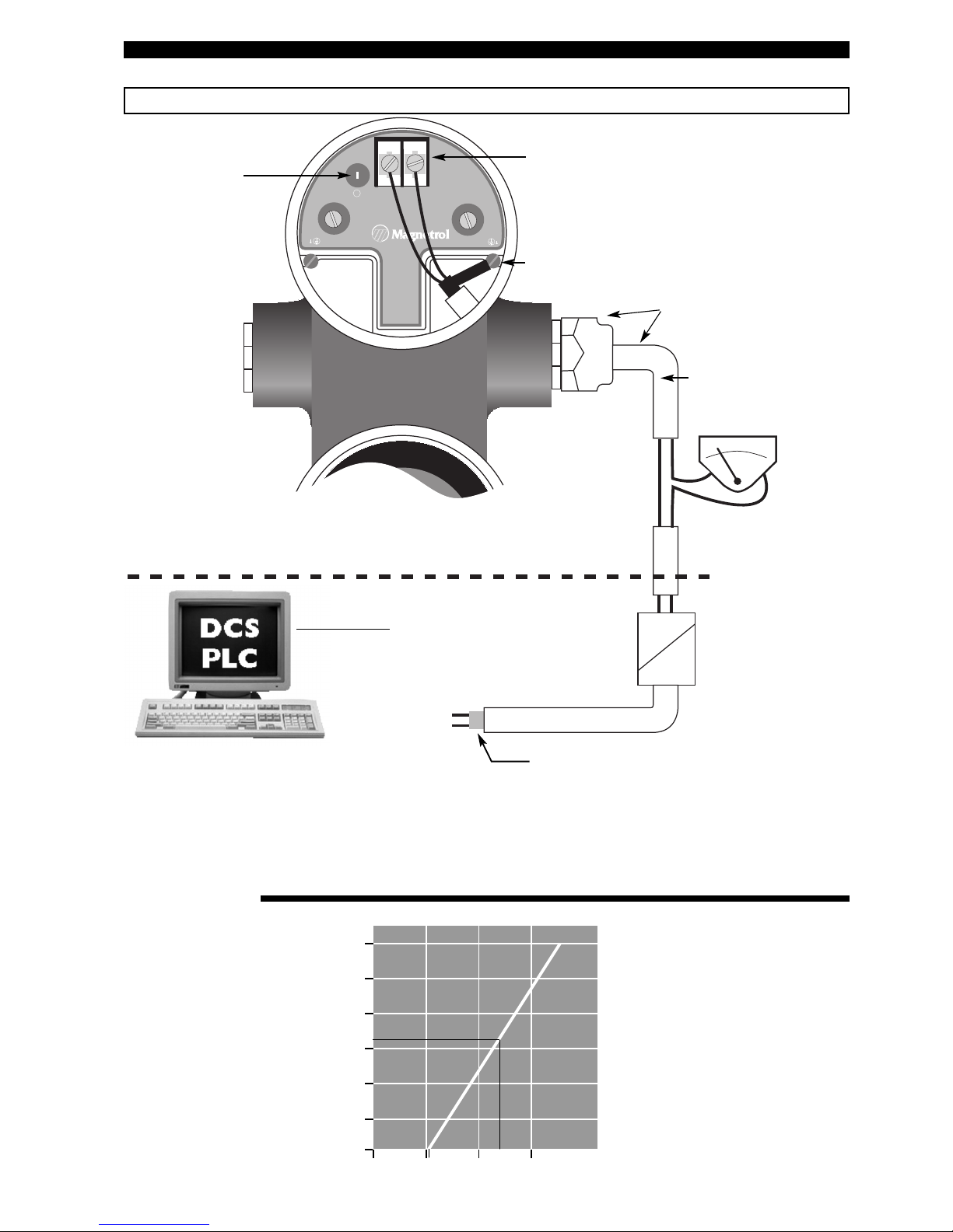
WIRING
CAUTION: power must be switched OFF before wiring the unit.
–+
I
S
®
–
L
OOP
C
URRENT
IS
0 %
100 %
Positive supply to (+) terminal
N
egative supply to (-) terminal
Shield wire to green grounding screw (resistance to
ground must be < 1 Ω).
Standard shielded twisted
pair cable recommended.
Non shielded cable can be
used per NAMUR NE 21
for field strenghts up to
10 V/m).
Use certified flameproof cable
gland(s) and cable for Explosion
proof area.
Current loop test
point (HART
®
only)
ANALOG I/O
or
DIGITAL I/O
(only for units with HART)
Customer supplied
local current meter
Do not connect shield
Ex
Non Ex
Ex
Non Ex
Ex
Non Ex
IMPORTANT:
The shield wire should only be grounded at ONE side only. It is recommended to connect the shield to ground in the field (at
the transmitter side - as shown above) but connecting in the control room is also allowed.
LOOP RESISTANCE
1200
1000
800
600
400
200
0
0 10 20 30 40 Vdc
20,5 mA
24 Vdc
630
11
Ω
Galvanic Barrier (only needed for intrinsically safe units):
HART
®
: max. 28,4 V DC @ 124 mA
Foundation Fieldbus™ / Profibus PA™: max. 17,5 V DC
@ 380 mA
10
Display Action Comment
Units!
cm
Units
cm
Units!
cm
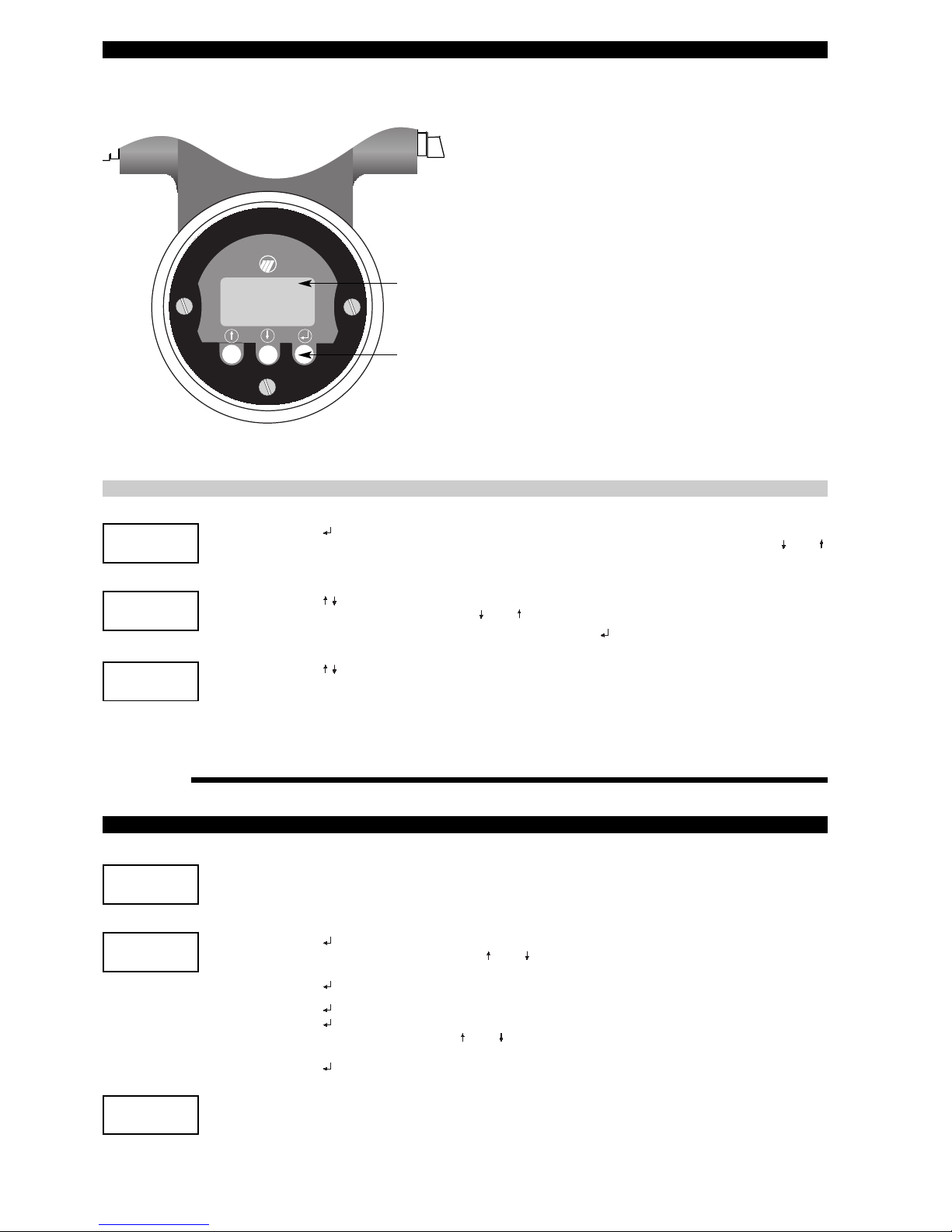
CONFIGURATION
NOTE: When connected to an approved barrier, the intrinsically safe electronics of the Eclipse allow to remove the
covers with power switched on – even if the area is known to be hazardous
2 line – 8 characters LCD
Default display cycles every 5 s through Status «STATUS» / Level
«
LEVEL» / % output «% OUTPUT» / Loop «LOOP».
Up/Down and Enter pushbuttons
IMPORTANT: The Eclipse amplifier can be bench configured without GWR
probe connected. Ignore the start up message «No Level Signal» / «STA-
TUS» / «WeakSgnl» in this case.
Press :
The last character on the first line of the display changes to «!». This sign confirms that the values/choices of the second line can be modified via the and
push buttons.
Press
*
Scroll through the choices or increase/decrease the values on the second line
of the display by and pushbuttons.
*
Accept values/choices as selected by pushbutton.
Press
Scroll through the menu.
PASSWORD
DISPLAY ACTION COMMENT
Ent Pass
0
New Pass
4096
Ent Pass!
1
NOTE: Password protection is activated when after 5 minutes no keystrokes are sensed.
Display shows «0»
Factory default setting
Data is not protected
Press and last character changes into «!»
Enter your personal password with and
(any value between 1 and 255)
Press to confirm
Setting password
Press and enter old password
Press and last character changes into «!»
Enter your new password with and
(any value between 1 and 255)
Press to confirm
Changing password
Display shows an encrypted value, enter your password
or call Magnetrol for assistance to recoop your password
if necessary
Data is protected by a valid
Password
11
20 mA Level
(100%-point)
Reference
point
Probe Type
Probe
L
ength
Offset
Safety
Zone
Inch or cm
Dielectric
o
f medium
Blocking
distance
4 mA Level
(
0%-point)
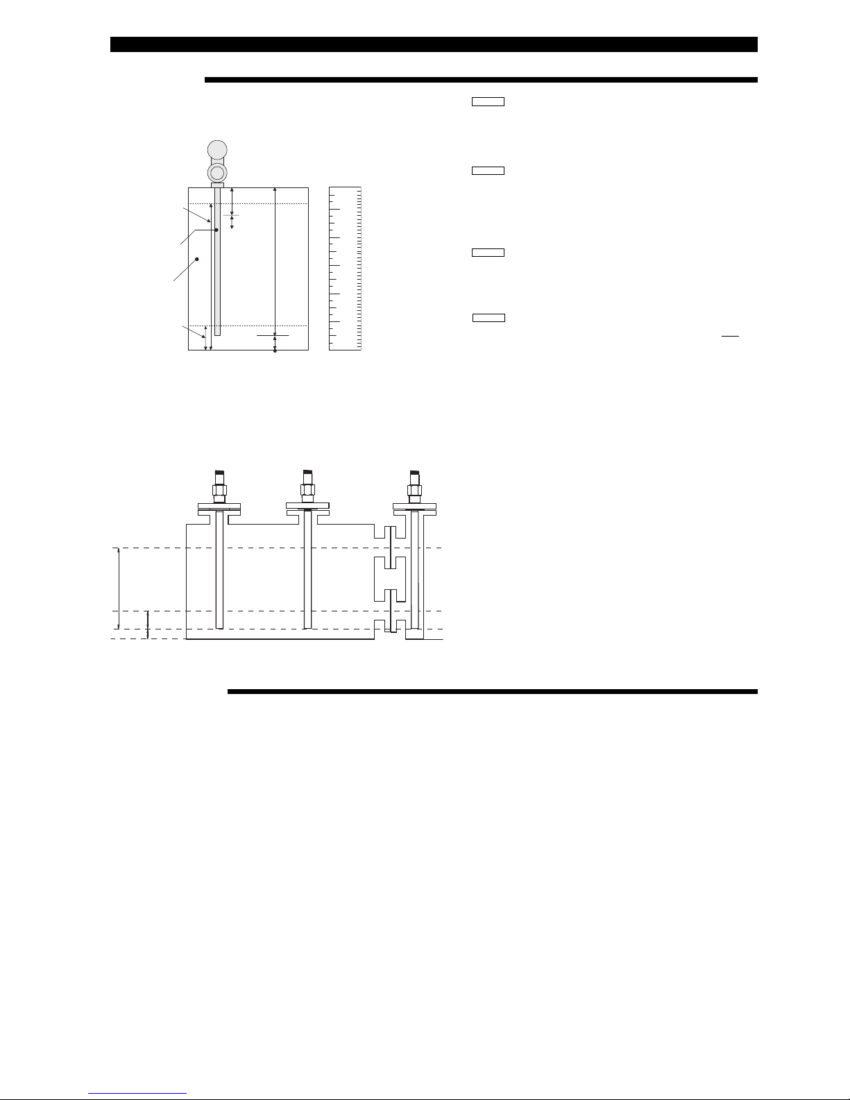
TERMINOLOGY
BEFORE STARTING
Offset = cm or inches
The offset is the distance between reference point (e.g.
bottom of tank) and end of probe. From the reference point
both 4 mA and 20 mA levels are calibrated. When offset is
set at zero, the end of the probe is the reference point.
4 mA Level = cm or inches
or zero level point, is measured from the reference point.
The unit has a transition zone at the bottom of the probe.
Min. level to enter for media with:
ε
r = 2.0: 150 mm (6") + Offset
ε
r = 80: 25 mm (1") + Offset
20 mA Level = cm or inches
or 100 % level point, is measured from the reference point.
The unit has a transition zone at the top of the probe.
Transition zone varies depending on probe type and
media: see probe specifications page 34 and continuing.
P
robe length = cm or inches, record the exact probe length as
printed on the nameplate: 705-xxxx-xxx / 7Mx-xxx-xxx
Dielectric Select the dielectric scale of the media to measure: 1.4–
1.7 or 1.7–3 or 3–10 or 10–100. When the dielectric is
known, it will enhance the overall accuracy of the unit but
select the dielectric scale ALWAYS to the lowest expected
dielectricum.
CONFIGURATION
Start from run mode:
1. Select the desired language for configuration: English, French, German or Spanish in the language screen (32)
«language». Scroll up for quickly reaching the language selection screen.
2. Define type of measurement:
a. Level only (pages 12 & 13)
b. Level and Volume (pages 14 & 15)
c. Interface only (pages 16 & 17)
d. Interface and Volume (pages 18 & 19)
Scroll down until the screen reads «MeasType». The unit will now show only the applicable screens for the selected type
of measurement.
3. Scroll one screen down and select the applicable engineering unit in «LvlUnits», all configuration values will be entered
in that engineering unit.
4. Move to the loop control screen «LoopCtrl», select the loop control in function of the type of measurement «MeasType»
selected.
5. Refer to the configuration procedure of the selected type of measurement.
6. Refer to page 20 for all hidden diagnostic screens and advanced configuration parameters. These screens allow the
advanced user to configure the unit for special applications or to troubleshoot the unit in the field. It is NOT recommended
to access this toolset without proper guidance or having followed proper training.
No offset
(Offset at 0 cm)
Positive offset
(Offset at 10 cm)
Negative offset
(Offset at -15 cm)
75 cm
100 %
0 %
15 cm
10 cm
20 mA = 75 cm
4 mA = 15 cm
20 mA = 85 cm
4 mA = 25 cm
20 mA = 60 cm
4 mA = 0 cm
Safety zone: In addition to the blocking distance,
the user can introduce a safety zone
to warn for liquid level entering this
zone beneath the blocking distance.
The loop signal will shift in this zone
to a selectable fault signal. The unit
will go to normal read out, when level
drops lower than the safety zone,
unless a latched fault signal is used.
The safety zone is disabled from factory. Safety zone related settings
include:
«SZ Fault»: to select the preferred
error signal
«SZ Height»: to define the safety
zone area
«SZ Alarm Reset»: to manually
reset a latched «SZ Fault»
12
= Quick Start up
MENU: STEP BY STEP PROCEDURE – Eclipse 705: Level only
Screen Action Comment
Run modeConfiguration
1
2
3
4
7
10
12
13
16
17
*Status*
*
Level*
*%Output*
*Loop*
Level
xx.x
%Output
xx.x%
Loop
xx.xx mA
5
PrbModel
(select)
MeasType
(select)
6
PrbMount
(select)
9
Probe Ln
xxx.x
8
LvlUnits
(select)
Lvl Ofst
xxx.x
1
1
Dielctrc
(Select)
Senstvty
xxx
Loop Ctrl
(Select)
14
Set 4mA
xxx.x
Damping
xx sec
15
Set 20mA
xxx.x
Fault
(Select)
T
ransmitter Display
T
ransmitter default values cycle every 5 seconds. Status «Status»,
L
evel «Level», % Output «% Output», and Loop «Loop».
T
ransmitter Display
T
ransmitter displays level value in selected engineering units.
Transmitter Display Transmitter displays % Output measurement derived from 20 mA
span.
T
ransmitter Display
T
ransmitter displays Loop measurement (mA).
Select the type of probe Select as per the 3 first digits of the probe partnumber. The partnumber
i
s shown on the nameplate: e.g. 705-510A-A11/7MT-A230-218, select
7
xT-x from the list.
S
elect the type of probe
m
ounting.
Select NPT «NPT», BSP «BSP» or Flange «Flange». (consult facto-
ry when a «7xK» GWR probe is used)
Select the type of measurement
Select level «Levl Only».
S
elect units for level
c
m «cm», m «m», inches «inches» or feet «feet».
E
nter the exact length of
p
robe.
E
nter as per the 3 last digits of the probe partnumber on the nameplate:
- rigid probes, enter value cm or inches,
-
flexible probes, enter value in meters or feet
e
.g. 705-510A-A11/7MR-A230-218, enter «218» cm probe length.
Enter the offset value. When entering configuration values from the end of the probe is
cumbersome, an offset can be introduced to determine a new
reference point. This reference point can be either below the probe
(positive offset) or at the probe (negative offset). See page 11
“Terminology”.
Enter the dielectric range
value of the media
Select: «
1.4–1.7»; «1.7–3»; «3–10» or «10–100»
«1.7–3» is recommended for dielectrics ≥ 1,7
Enter sensitivity value Allows fine adjustment of internal gain.
Select primary variable (PV)
Primary variable is the loop controlling parameter. Select level
«Lvl only»
Enter the level value
for the 4 mA point.
A transition zone may exist at the bottom of the probe. See Functional
Specifications Probe, see page 34 and continuing.
Enter the level value
for the 20 mA point.
A transition zone / blocking distance may exist at the top of the probe.
See Functional Specifications Probe, see page 34 and continuing.
Enter the damping factor. A Damping factor (1-10 seconds) may be added to smooth a noisy
display and/or output due to turbulence.
Enter the value for error.
Select «3.6 mA», «22 mA» or hold last value «HOLD». In case of
loop failure, error signal will follow the failing trend; meaning the unit
will show 3.6 mA when the reviewed loop current by the device is
found too low. The unit will show 22 mA in case the reviewed loop
current is found too high.
13
MENU: STEP BY STEP PROCEDURE – Eclipse 705: Level only
Screen Action Comment
Diagnostics
23
2
6
27
28
29
30
Poll Adr
xx
Trim 4
xxxx
2
5
Trim Lvl
xx.x
2
4
Loop Mode
Trim 20
xxxx
Loop Tst
xx.x mA
LvlTicks
xxxxx
New Pass
xxx
31
32
Language
Mdl705HT
Ver xx.xx
33
DispFact
(select)
18
19
20
2
1
22
BlockDis
xx.x
SZ Fault
(select)
SZHeight
xx.x
SZ Alarm
Reset
Threshld
(select)
E
nter distance in
selected level units
A
llows to ignore level measurements near the top of the probe,
caused by e.g. condensation, crystalization. Make sure that the liquid
level does NOT enter this zone. Consult factory or the
‘Troubleshooting’ section before entering any value. Normaly to be
u
sed with single rod probe.
Select the safety zone fault.
Select «None» (None), «3.6mA», «22mA», «Latch 3.6mA» or
«
Latch 22mA». When either «Latch 3.6 / 22mA» signals is
s
elected, the loop current remains in alarm until it is manually cleared
w
ith the «SZAlarm» screen ( for safety zone explanation see
T
erminology - page 11).
S
elect the safety zone value
E
nter safety zone in cm or inches (see Terminology - page 11).
Reset safety zone latch fault
Clear a latched safety zone alarm «SZFault».
S
elect the type of threshold
«
Fixed» = the first reflection from the top will be considered as level
(
default setting)
«
CFD» = the strongest reflection from the top will be considered as
l
evel.
O
nly change to «CFD», in case the unit is reading incorrect level.
A
djustment of trim level «Trim Lvl» may be necessary when
t
hreshold is changed.
Enter HART ID number. Select a HART poll address (0-15). Enter 0 for a single transmitter
installation.
E
nable/Disable
D
etermines whether the loop is fixed at 4.0 mA or controlled by the
PV.
E
nter value
t
o adjust level reading.
A
llows to compensate for a fixed level deviation.
Fine tune the 4 mA point. Attach a mA meter to the output. If the output does not equal 4.0 mA,
adjust the value on the display to equal 4.00 mA.
Fine tune the 20 mA point. Attach a mA meter to the output. If the output does not equal
20.0 mA, adjust the value on the display to equal 20.00 mA.
Enter a mA output value. Set mA Output to any given value to perform loop test .
Diagnostic display. Shows time of flight from fiducial pulse to reflected signal from level.
Enter new password. Use arrows to select desired value. Values between 0 and 255.
Select language
Select «English», «Français», «Deutsch» or «Espagnol».
None, do not adjust.
Factory setting. «Ver» refers to software version.
Advanced diagnostics. See page 20.
No offset
(Offset at 0 cm)
Positive offset
(Offset at 10 cm)
Negative offset
(Offset at -15 cm)
75 cm
100 %
0 %
15 cm
10 cm
20 mA = 75 cm
4 mA = 15 cm
20 mA = 85 cm
4 mA = 25 cm
20 mA = 60 cm
4 mA = 0 cm
OFFSET
14
= Quick Start up
MENU: STEP BY STEP PROCEDURE – Eclipse 705: Level & Volume
Screen Action Comment
Run mode
Configuration
1
2
3
4
8
11
12
13
19
20
*Status*
*
Volume*
*%Output*
*Loop*
Volume
xxx
%Output
xx.x%
Loop
xx.xx mA
5
Level
xxx
MeasType
(select)
7
PrbMount
(select)
6
PrbModel
(select)
1
0
Probe Ln
xxx.x
9
LvlUnits
(select)
Lvl Ofst
xxx.x
14
Dielctrc
(Select)
VolUnits
(select)
StrapTbl
xx pnts
17
Set 4mA
xxx.x
Damping
xx sec
18
Set 20mA
xxx.x
15
Senstvty
xxx
16
Loop Ctrl
(Select)
Fault
(Select)
T
ransmitter Display
T
ransmitter default values cycle every 5 seconds. Status «Status»,
V
olume «Volume», % Output «% Output», and Loop «Loop».
T
ransmitter Display
T
ransmitter displays Volume Value in selected engineering units.
Transmitter Display Transmitter displays % Output measurement derived from 20 mA
span.
T
ransmitter Display
T
ransmitter displays Loop measurement (mA).
Transmitter Display
Transmitter displays level in selected volume units «LvlUnits».
S
elect the type of probe
S
elect as per the 3 first digits of the probe partnumber. The partnumber
i
s shown on the nameplate: e.g. 705-510A-A11/7MT-A230-218, select
7xT-x from the list.
Select the type of probe
mounting.
S
elect NPT «NPT», BSP «BSP» or Flange «Flange».
(consult facto-
ry when a «
7xK» GWR probe is used)
Select the type of measurement
Select level and volume «Lvl&Vol».
S
elect units for level
c
m «cm», m «m», inches «inches» or feet «feet».
Enter the exact length of
probe.
Enter as per the 3 last digits of the probe partnumber on the nameplate:
- rigid probes, enter value cm or inches,
- flexible probes, enter value in meters or feet
e
.g. 705-510A-A11/7MR-A230-218, enter «218» cm probe length.
Enter the offset value. When entering configuration values from the end of the probe is
cumbersome, an offset can be introduced to determine a new
reference point. This reference point can be either below the probe
(positive offset) or at the probe (negative offset). See page 11
“Terminology”.
Select units for volume
Liters «l» or gallons «g».
Enter level/volume
pairs in max 20 steps
Liters «l» or gallons «g».
Enter the dielectric range
value of the media
Select: «
1.4–1.7»; «1.7–3»; «3–10» or «10–100»
«1.7–3» is recommended for dielectrics ≥ 1,7
Enter sensitivity value Allows fine adjustment of internal gain.
Select primary variable (PV)
Primary variable is the loop controlling parameter. Select level
«Lvl only» or volume «volume»
Enter the level value
for the 4 mA point.
A transition zone may exist at the bottom of the probe. See Functional
Specifications Probe, see page 34 and continuing.
Enter the level value
for the 20 mA point.
A transition zone / blocking distance may exist at the top of the probe.
See Functional Specifications Probe, see page 34 and continuing.
Enter the damping factor. A damping factor (1-10 seconds) may be added to smooth a noisy
display and/or output due to turbulence.
Enter the value for error.
Select «3.6 mA», «22 mA» or hold last value «HOLD». In case of
loop failure, error signal will follow the failing trend; meaning the unit
will show 3.6 mA when the reviewed loop current by the device is
found too low. The unit will show 22 mA in case the reviewed loop
current is found too high.
15
MENU: STEP BY STEP PROCEDURE – Eclipse 705: Level & Volume
Screen Action Comment
Advanced configurationDiagnostics
26
29
30
31
32
33
Poll Adr
xx
Trim 4
xxxx
28
Trim Lvl
xx.x
27
Loop Mode
Trim 20
xxxx
Loop Tst
xx.x mA
LvlTicks
xxxxx
New Pass
xxx
34
35
Language
Mdl705HT
Ver xx.xx
21
22
23
2
4
25
BlockDis
x.x
SZ Fault
(select)
SZHeight
xx.x
SZ Alarm
Reset
Threshld
(select)
E
nter distance in
selected level units
A
llows to ignore level measurements near the top of the probe,
caused by e.g. condensation, crystalization. Make sure that the liquid
level does NOT enter this zone. Consult factory or the
‘Troubleshooting’ section before entering any value. Normaly to be
u
sed with single rod probe.
Select the safety zone fault.
Select «None» (None), «3.6mA», «22mA», «Latch 3.6mA» or
«
Latch 22mA». When either «Latch 3.6 / 22mA» signals is
s
elected, the loop current remains in alarm until it is manually reset
w
ith the «SZAlarm» reset screen ( for safety zone explanation see
T
erminology - page 11).
S
elect the safety zone value
E
nter safety zone in cm or inches (see Terminology - page 11).
Reset safety zone latch fault
Select «Reset» «No» or «Yes» to reset alam when either «Latch
3.6mA» or «Latch 22mA» was selected in «SZFault».
S
elect the type of threshold
«
Fixed» = the first reflection from the top will be considered as level
(
default setting)
«
CFD» = the strongest reflection from the top will be considered as
l
evel.
O
nly change to «CFD», in case the unit is reading incorrect level.
A
djustment of trim level «Trim Lvl» may be necessary when
t
hreshold is changed.
Enter HART ID number. Select a HART poll address (0-15). Enter 0 for a single transmitter
i
nstallation.
E
nable/Disable
D
etermines whether the loop is fixed at 4.0 mA or controlled by the
PV.
E
nter value
t
o adjust level reading.
A
llows to compensate for a fixed level deviation.
Fine tune the 4 mA point. Attach a mA meter to the output. If the output does not equal 4.0 mA,
adjust the value on the display to equal 4.00 mA.
Fine tune the 20 mA point. Attach a mA meter to the output. If the output does not equal
20.0 mA, adjust the value on the display to equal 20.00 mA.
Enter a mA output value. Set mA Output to any given value to perform loop test.
Diagnostic display. Shows time of flight from fiducial pulse to reflected signal from level.
Enter new password. Use arrows to select desired value. Values between 0 and 255.
Select language
Select «English», «Français», «Deutsch» or «Espagnol».
None, do not adjust.
Factory setting. «Ver» refers to software version.
Advanced diagnostics. See page 20.
Strapping table
max. Pt 20 Lvl = ...... cm
Pt 4 Lvl = 200 cm
Pt 3 Lvl = 120 cm
Pt 2 Lvl = 50 cm
Pt 1 Lvl = 0 cm
max. Pt 20 Vol = ...... l
Pt 4 Vol = 3000 l
Pt 3 Vol = 2000 l
Pt 2 Vol = 1000 l
Pt 1 Vol = 0 l
36
DispFact
(select)
NOTE: Consult page 13 for level offset «Lvl Ofst» details.
16
= Quick Start up
MENU: STEP BY STEP PROCEDURE – Eclipse 705: Interface
Screen Action Comment
Run mode
Configuration
1
2
3
4
8
1
1
12
15
18
19
*Status*
*
IfcLevel*
*%Output*
*Loop*
IfcLevel
xx.x
%Output
xx.x%
Loop
xx.xx mA
5
Level
xxx
MeasType
(select)
7
PrbMount
(select)
6
PrbModel
(select)
1
0
Probe Ln
xxx.x
9
LvlUnits
(select)
Lvl Ofst
xxx.x
13
Dielctrc
(Select)
14
Senstvty
xxx
Upr Diel
(Select)
Loop Ctrl
(Select)
16
Set 4mA
xxx.x
Damping
xx sec
17
Set 20mA
xxx.x
Fault
(Select)
T
ransmitter Display
T
ransmitter default values cycle every 5 seconds. Status «Status»,
I
nterface level «Ifclevel», % Output «% Output», and Loop
«
Loop».
T
ransmitter Display
T
ransmitter displays interface level in selected engineering units.
Transmitter Display Transmitter displays % Output measurement derived from 20 mA
span.
T
ransmitter Display
T
ransmitter displays Loop measurement (mA).
Transmitter Display
Transmitter displays interface level in selected level units «LvlUnits».
S
elect the type of probe
S
elect as per the 3 first digits of the probe partnumber. The partnumber
is shown on the nameplate: e.g. 705-510A-A11/7MT-A230-218, select
7xT-x from the list.
S
elect the type of probe
m
ounting.
Select NPT «NPT», BSP «BSP» or Flange «Flange». (consult facto-
ry when a «
7xK» GWR probe is used)
Select the type of measurement
Select interface «Interface».
Select units for level
cm «cm», m «m», inches «inches» or feet «feet».
E
nter the exact length of
probe.
E
nter as per the 3 last digits of the probe partnumber on the nameplate:
-
rigid probes, enter value cm or inches,
-
flexible probes, enter value in meters or feet
e.g. 705-510A-A11/7MR-A230-218, enter «218» cm probe length.
Enter the offset value. When entering configuration values from the end of the probe is
cumbersome, an offset can be introduced to determine a new
reference point. This reference point can be either below the probe
(positive offset) or at the probe (negative offset). See page 11
“Terminology”.
Enter the dielectric range
value of the upper media.
Enter the dielectrics of the upper layer liquid (between 1,4 and 5,0) –
only upper layer dielectrics need to be entered.
Select the dielectric range
value of the lower media
Select: «
10–100»
Enter sensitivity value
Allows fine adjustment of internal gain.
Select primary variable (PV)
Primary variable is the loop controlling parameter. Select interface level «Ifc Level» or top level «Lvl Only»
Enter the level value
for the 4 mA point.
A transition zone may exist at the bottom of the probe. See Functional
Specifications Probe, see page 34 and continuing.
Enter the level value
for the 20 mA point.
A transition zone / blocking distance may exist at the top of the probe.
See Functional Specifications Probe, see page 34 and continuing.
Enter the damping factor. A damping factor (1-10 seconds) may be added to smooth a noisy
display and/or output due to turbulence.
Enter the value for error.
Select «3.6 mA», «22 mA» or hold last value «HOLD». In case of
loop failure, error signal will follow the failing trend; meaning the unit
will show 3.6 mA when the reviewed loop current by the device is
found too low. The unit will show 22 mA in case the reviewed loop
current is found too high.
17
MENU: STEP BY STEP PROCEDURE – Eclipse 705: Interface
Screen Action Comment
26
25
3
0
31
32
35
Poll Adr
xx
IfcThrs
(select)
2
4
Threshld
Trim 20
xxxx
Loop Tst
xx.x mA
28
29
Trim Lvl
xx.x
2
7
Loop Mode
Trim 4
xxxx
LvlTicks
xxxxx
New Pass
xxx
36
37
Language
Mdl705HT
Ver xx.xx
33
34
IfcTicks
xxxx
Medium
20
21
22
2
3
BlockDis
x.x
SZ Fault
(select)
SZHeight
xx.x
SZ Alarm
Reset
E
nter distance in
selected level units
A
llows to ignore level measurements near the top of the probe,
caused by e.g. condensation, crystalization. Make sure that the liquid
level does NOT enter this zone. Consult factory or the
‘Troubleshooting’ section before entering any value. Normaly to be
u
sed with single rod probe.
Select the safety zone fault.
Select «None» (None), «3.6mA», «22mA», «Latch 3.6mA» or
«
Latch 22mA». When either «Latch 3.6 / 22mA» signals is
s
elected, the loop current remains in alarm until it is manually reset
w
ith the «SZAlarm» reset screen ( for safety zone explanation see
T
erminology - page 11).
S
elect the safety zone value
E
nter safety zone in cm or inches (see Terminology - page 11).
Reset safety zone latch fault
Clear a latched safety zone alarm «SZFault».
S
elect top level threshold.
D
efault selection for most common applications is «Fixed».
S
elect interface threshold.
D
efault selection for all applications is «CFD». In case the unit does
not track the correct interface layer, select «Fixed».
Enter HART ID number. Select a HART poll address (0-15). Enter 0 for a single transmitter
installation.
E
nable/Disable
D
etermines whether the loop is fixed at 4.0 mA or controlled by the
P
V.
Enter value
to adjust level reading.
Allows to compensate for a fixed level deviation.
Fine tune the 4 mA point. Attach a mA meter to the output. If the output does not equal 4.0 mA,
adjust the value on the display to equal 4.00 mA.
Fine tune the 20 mA point. Attach a mA meter to the output. If the output does not equal
20.0 mA, adjust the value on the display to equal 20.00 mA.
Enter a mA output value. Set mA Output to any given value to perform loop test .
Diagnostic display. Shows time of flight from fiducial pulse to reflected signal from level.
Diagnostic display. Shows time of flight through the upper liquid layer.
Diagnostic display.
Shows type of detected upper liquid; unknown «Unknown» oil only
«Oil Only», thin oil layer «Thin Oil», thick oil layer «Thick
Oil», or no level «Dry Probe».
Enter new password. Use arrows to select desired value. Values between 0 and 255.
Select language
Select «English», «Français», «Deutsch» or «Espagnol».
None, do not adjust.
Factory setting. «Ver» refers to software version.
Advanced diagnostics. See page 20.
38
DispFact
(select)
No offset
(Offset at 0 cm)
Positive offset
(Offset at 10 cm)
Negative offset
(Offset at -15 cm)
75 cm
100 %
0 %
15 cm
10 cm
20 mA = 75 cm
4 mA = 15 cm
20 mA = 85 cm
4 mA = 25 cm
20 mA = 60 cm
4 mA = 0 cm
OFFSET
Advanced configuration
Diagnostics

18
= Quick Start up
MENU: STEP BY STEP PROCEDURE – Eclipse 705: Interface & Volume
Screen Action Comment
Run modeConfiguration
1
2
3
4
7
13
16
19
22
23
*Status*
*
IfcVol*
*%Output*
*Loop*
IfcLevel
or Ifc Vol
%Output
xx.x%
Loop
xx.xx mA
6
Volume
xx.x
Level
xxxx
5
IfcLvl
xxxx
12
Probe Ln
xxx.x
11
LvlUnits
(select)
Lvl Ofst
xxx.x
17
Dielctrc
(Select)
Upr Diel
(Select)
Loop Ctrl
(Select)
14
VolUnits
Damping
xx s
15
StrapTbl
xx pnts
Fault
(Select)
T
ransmitter Display
T
ransmitter default values cycle every 5 seconds. Status «Status»,
I
nterface volume «IfcVolume», % Output «% Output», and Loop
«
Loop».
T
ransmitter Display
T
ransmitter displays Interface volume or Interface level in selected
engineering units (depending selection in Loop control «Loop Ctrl»
Transmitter Display Transmitter displays % Output measurement derived from 20 mA
span.
T
ransmitter Display
T
ransmitter displays Loop measurement (mA).
Transmitter Display Transmitter displays interface level in selected level units
«LvlUnits».
T
ransmitter Display
T
ransmitter displays volume in selected volume units «VollUnits».
Transmitter Display
Transmitter displays level in selected level units «LvlUnits».
S
elect the type of probe
S
elect as per the 3 first digits of the probe partnumber. The partnumber
i
s shown on the nameplate: e.g. 705-510A-A11/7MT-A230-218, select
7xT-x from the list.
Select the type of probe
mounting.
S
elect NPT «NPT», BSP «BSP» or Flange «Flange».
(consult facto-
ry when a «
7xK» GWR probe is used)
S
elect the type of measurement
S
elect interface - volume «IfcVol».
S
elect units for level
c
m «cm», m «m», inches «inches» or feet «feet».
Enter the exact length of
probe.
Enter as per the 3 last digits of the probe partnumber on the nameplate:
- rigid probes, enter value cm or inches,
- flexible probes, enter value in meters or feet
e.g. 705-510A-A11/7MR-A230-218, enter «218» cm probe length.
Enter the offset value. When entering configuration values from the end of the probe is
cumbersome, an offset can be introduced to determine a new
reference point. This reference point can be either below the probe
(positive offset) or at the probe (negative offset). See page 11
“Terminology”.
Select units for volume.
Liters «l» or gallons «g».
Enter level/volume
pairs in max 20 steps
Liters «l» or gallons «g».
Enter the dielectric range
value of the upper media.
Enter the dielectrics of the upper layer liquid (between 1,4 and 5,0) –
only upper layer dielectrics need to be entered.
Select the dielectric range
value of the lower media
Select:
«10–100»
Enter sensitivity value Allows fine adjustment of internal gain.
Select primary variable (PV)
Primary variable is the loop controlling parameter. Select interface level «IfcLevel» or interface volume «Ifc Vol»
Enter the level value
for the 4 mA point.
A transition zone may exist at the bottom of the probe. See Functional
Specifications Probe, see page 34 and continuing.
Enter the level value
for the 20 mA point.
A transition zone / blocking distance may exist at the top of the probe.
See Functional Specifications Probe, page 34 and continuing.
Enter the damping factor. A damping factor (1-10 seconds) may be added to smooth a noisy
display and/or output due to turbulence.
Enter the value for error.
Select «3.6 mA», «22 mA» or hold last value «HOLD». In case of
loop failure, error signal will follow the failing trend; meaning the unit
will show 3.6 mA when the reviewed loop current by the device is
found too low. The unit will show 22 mA in case the reviewed loop
current is found too high.
10
8
PrbModel
(select)
MeasType
(select)
9
PrbMount
(select)
18
Senstvty
xxx
20
Set 4mA
xxx.x
21
Set 20mA
xxx.x

19
MENU: STEP BY STEP PROCEDURE – Eclipse 705: Interface & Volume
Screen Action Comment
3
1
29
34
35
36
39
Loop Mode
30
Poll Adr
xx
IfcThrsh
(select)
2
8
Threshld
Trim 20
xxxx
Loop Tst
xx.x mA
LvlTicks
xxxxx
New Pass
xxx
40
41
Language
Mdl705HT
Ver xx.xx
37
38
IfcTicks
xxxx
Medium
24
25
26
2
7
BlockDis
x.x
SZ Fault
(select)
SZHeight
xx.x
SZ Alarm
Reset
E
nter distance in
selected level units
A
llows to ignore level measurements near the top of the probe,
caused by e.g. condensation, crystalization. Make sure that the liquid
level does NOT enter this zone. Consult factory or the
‘Troubleshooting’ section before entering any value. Normaly to be
u
sed with single rod probe.
Select the safety zone fault.
Select «None» (None), «3.6mA», «22mA», «Latch 3.6mA» or
«
Latch 22mA». When either «Latch 3.6 / 22mA» signals is
s
elected, the loop current remains in alarm until it is manually reset
w
ith the «SZAlarm» reset screen ( for safety zone explanation see
T
erminology - page 11).
S
elect the safety zone value
E
nter safety zone in cm or inches (see Terminology - page 11).
Reset safety zone latch fault
Clear a latched safety zone alarm «SZFault».
S
elect top level threshold.
D
efault selection for most common applications is «Fixed».
Select interface threshold.
Default selection for all applications is «CFD». In case the unit does
not track the correct interface layer, select «Fixed».
Enter HART ID number. Select a HART poll address (0-15). Enter 0 for a single transmitter
installation.
E
nable/Disable
D
etermines whether the loop is fixed at 4.0 mA or controlled by the
P
V.
Enter value
to adjust level reading.
Allows to compensate for a fixed level deviation.
Fine tune the 4 mA point. Attach a mA meter to the output. If the output does not equal 4.0 mA,
a
djust the value on the display to equal 4.00 mA.
Fine tune the 20 mA point. Attach a mA meter to the output. If the output does not equal
20.0 mA, adjust the value on the display to equal 20.00 mA.
Enter a mA output value. Set mA Output to any given value to perform loop test .
Diagnostic display. Shows time of flight from fiducial pulse to reflected signal from level.
Diagnostic display. Shows time of flight through the upper liquid layer.
Diagnostic display.
Shows type of detected upper liquid; unknown «Unknown» oil only
«Oil Only», thin oil layer «Thin Oil», thick oil layer «Thick
Oil» or no level «Dry Probe».
Enter new password. Use arrows to select desired value. Values between 0 and 255.
Select language
Select «English», «Français», «Deutsch» or «Espagnol».
None, do not adjust.
Factory setting. «Ver» refers to software version.
Advanced diagnostics. See page 20.
Strapping table
max. Pt 20 Lvl = ...... cm
Pt 4 Lvl = 200 cm
Pt 3 Lvl = 120 cm
Pt 2 Lvl = 50 cm
Pt 1 Lvl = 0 cm
max. Pt 20 Vol = ...... l
Pt 4 Vol = 3000 l
Pt 3 Vol = 2000 l
Pt 2 Vol = 1000 l
Pt 1 Vol = 0 l
32
3
3
Trim Lvl
xx.x
Trim 4
xxxx
42
DispFact
(select)
NOTE: Consult page 17 for level offset «Lvl Ofst» details.
Advanced configurationDiagnostics

20
MENU: STEP BY STEP PROCEDURE: ADVANCED CONFIGURATION
Screen Action Comment
Diagnostics
1
3
4
6
7
8
DispFact
Select
Run time
xx h
2
History
(current status)
History
Reset
FidTicks
xxxx
5
HF cable
(select)
14
Ifc Ampl
xxx
FidSprd
X
Fid Type
(select)
9
10
20
Fid Gain
xxx
Window
xxx
11
Conv Fct
xxxx
1
2
Scl Ofst
xxx
13
Neg Ampl
xxx
15
Pos Ampl
xxx
16
Signal
xxx
17
Compensate
(select)
18
DrateFct
Xxxx
19
Targ Ampl
Xxxx
Targ Tks
Xxxx
21
Targ Cal
Xxxx
22
OperMode
(select)
25
23
7xKCorr
xxx
24
ElecTemp
xxx C
Max Temp
xxx C
26
Min Temp
xxx C
27
SZ Hyst
xx.x
R
eview factory parameters
S
elect «YES» to reveal Factory parameters; «NO» to hide.
R
eview Diagnostic messages.
A
cumulative review of all diagnostic messages. Press the enter but-
t
on twice to clear.
Display mode. Shows time in hours that unit is in operation since last power on.
D
iagnostic display.
S
elect «YES» to clear «History».
S
uperuser parameter
S
elect from 1 m (3') or 3,6 m (12') remote.
D
iagnostic display.
S
hows time of flight from electronics to fiducial pulse. Value should
r
emain stable within ± 10 ticks.
D
iagnostic display.
V
alue represents the variation of fiducial ticks – a value indicates that
u
nit is OK, a problematic spread results into an error message.
Select fiducial pulse type.
Requires superuser password.
«positive» or «negative» (selection only allowed for some
probes). Consult factory before changing status.
C
hange gain.
V
alue represents the # of gain applied to the fiducial signal.
None, do not adjust. Factory setting.
None, do not adjust. Factory setting.
None, do not adjust. Factory setting.
Enter new value.
Requires superuser password.
Negative amplitude threshold.
Enter new value.
Requires superuser password.
Interface amplitude threshold.
Enter new value.
Requires superuser password.
Positive amplitude threshold.
Diagnostic display. Indication of signal strength.
Access compensation screens.
Requires superuser password.
«None» default.
The selection of «Manual» or «Auto» activates the screens 16
through 20 for 7MS/7MQ probes.
None, do not adjust.
Diagnostic display if «Compsate» is on «Auto».
Shows velocity derating factor.
None, do not adjust.
Diagnostic display if «Compsate» is on «Auto».
Shows amplitude of steam reference target.
Diagnostic display if «Compsate» is on «Auto».
Shows # of ticks from fiducial to steam reference target.
None, do not adjust.
Diagnostic display if «Compsate» is on «Auto».
Shows the calibrated # of ticks at ambient temperature.
Select operating mode.
Selection screen if «Compsate» is on «Auto».
Select run automatically «Run», calibrate «Cal», deactivate «Off».
Enter a value.
Requires additional password.
Distance in mm (regardless .«LvlUnits») from fiducial to user reference point. Only for 7EK (top/bottom) probe.
None, do not adjust. Shows internal housing temperature.
None, do not adjust. Diagnostic display, shows maximum internal housing temperature
recorded.
None, do not adjust. Diagnostic display, shows minimum internal housing temperature
recorded.
None, do not adjust. Safety zone Hysterisis, diagnostic factory setting
Hidden diagnostic screens. Do not acces without assistance or having followed advanced training.

21
For more details about the use of PACTware™ and FDT technology, refer to instruction manual 59-601
PACTware™ – Configuration and Troubleshooting
WHAT IS FDT, PACTware AND DTM
Power
Transmitter
HART connections
24 V DC
PC with
HART Serial
Interface
• FDT (Field Device Tool) is a new interface code that
describes the standardization between frame programs
(e.g, PACTware) and DTMs (Device Type Manager).
• PACTwa re (Process Automation Configuration Tool)
is a frame program. It is a device-independent software
program that communicates with all approved DTMs.
• DTM (Device Type Manager) is a device-specific software driver designed to operate within a FDT compatible
frame program such as PACTware. It includes all special
information needed to communicate with a specific
device (e.g, Pulsar RX5). There are two basic categories
of DTM’s—Communication (HART, Fieldbus
®
, Profibus®,
etc.) and Field Device (e.g. Pulsar RX5 Radar transmitter).
QUICK START
CONNECTIONS
1. Start a project
Open Pactware and add the Hart modem key and then
the Magnetrol instrument to your project.
Select: «Device» – «add device» – select device
(repeat for each device in your project)
Important: Make sure that the COM port settings for
y
our Hart modem key are correct;
2. Connect the devices
Select in the left window the Magnetrol instrument.
Select: «Device» – «connect» (both modem and
M
agnetrol instrument are getting connected)
3. Configure the instrument
Select: «Device» – «parameter» – «Online
parameterization»
O
pen «+ Main Menu» and select «+ Device set
up» – «Calibration»
Parameters can be changed in the window at right, via
the drop down boxes. ENTER confirms the change
online.
4. Troubleshoot / Monitior the instrument
Process trend:
Select: «Device» – «Additional functions» –
«Process Trend»
Process trend: all key data (level % Output, Loop, Signal
strength) can be trended and saved, time scales can be
adapted.
Echo Curve:
Select: «Device» – «Additional functions» –
«Echo Curve»
Echo Curve: shows the actual waveform. The echo
curve is an efficient tool for advanced calibration and
troubleshooting.
Present Status:
Open Main Menu and select «+ Device set up» –
«Diagnostics» – «Present status»
Present status: shows the entire overview of all
detectable faults and warnings. Blank boxes indicate the
healthy condition of the instrument. Ticked off boxes
indicate for a possible fault or warning.
The following diagram shows a typical hardware configuration. Observe all safety codes when attaching to instrument
loops in hazardous areas or when measuring flammable
media. Computers are not intrinsically safe devices.
Magnetrol recom-
mends the VIATOR
®
USB HART®Interface
from MACTek
®
Corporation.

22
PACTware™ – Configuration and Troubleshooting
Echo Curve patterns
N
ormal oil/water interface
Below screens are examples of the most typical echo curves that occur in normal operation / error condition.
Normal signal pulses from oil over water
L
evel with Blocking Distance correction
Signal pulse from level. Unit suffered from build up on top
of the probe. The introduced blocking distance (see area in
frame) solves the problem.
Dry Probe
Signal pulse from an empty vessel/ cage – displayed message on the unit is «DryProbe» Dry Probe
EOP High or Low
Signal pulse from an empty vessel or cage but with wrongly entered probe length – displayed message is «EOP
High» or «EOP Low» (as shown in graph). Correct the
probe length in either case.
Weak Signal
Signal pulse of a weak signal. Displayed message is
«WeakSgnl». Solve this by either to:
- change dielectric setting to a lower range or
- increase the sensitivity
Threshold Fixed or CFD
Signal pulse of oil over water level. Always select
«Threshld Fixed» (as shown in the graph). «Threshld
CFD» will track the stronger reflection pulse. In case of level
measurement, the unit will not compensate for the signal
velocity in the upper oil layer and show an erroneous level
reading.

23
CONFIGURATION USING HART
®
I
MPORTANT: The digital HART
®
c
ommunication is superimposed on the
4-20 mA loop and requires a min. load resistance of 250 Ω and a max load
resistance of 450 Ω.
+
+
-
-
Junction
C
ontrol
Room
Display
Power
Supply
Current
Meter
2
50 Ω < R
L
<
450 Ω
CONNECTIONS
CHECK HART
®
Connection of your Hart communicator:
• at power terminals (+) and (-) in wiring compartment
• at first junction box between unit and control room.
Before starting the HART
®
configuration procedure – check if your HART®commu-
n
icator is equipped with the proper Eclipse Device Descriptors (DD’s).
I/O start up the communicator
Select NO: go offline
Select 4: utility
Select 5: simulation
Check manufacturer: Magnetrol
HART MENU
I/O Start up the device
1 Enter Device Set Up «
DEVICE SET UP»
Press one of the following alphanumeric keys (if no key is sensed after 5 s, the
unit will automatically jump to RUN mode and alternatively show Level/% Output
and Loop signal
1 for entering Calibration «CALIBRATION» (see page 24 for additional informa-
tion)
2 for entering Basic Set Up «
BASIC SET UP» – general HART
3 for Advanced Set Up «
ADVANCED SET UP» (see page 24 for additional infor-
mation)
4 for entering Diagnostics «DIAGNOSTICS» (see page 24 for additional infor-
mation)
5 for entering Review «
REVIEW» to review all settings.
When the proper software version is not found, consult your local HART
®
Service
Center to load the correct Eclipse DD’s.
HCF Release Date
HART Version
Model
Compatible with software
September 2008 Dev V1 DD V2
705 3.x
Version 3.0A and later
February 2013 Dev V2 DD V2 Version 3.2A and later
24
CONFIGURATION USING HART
®
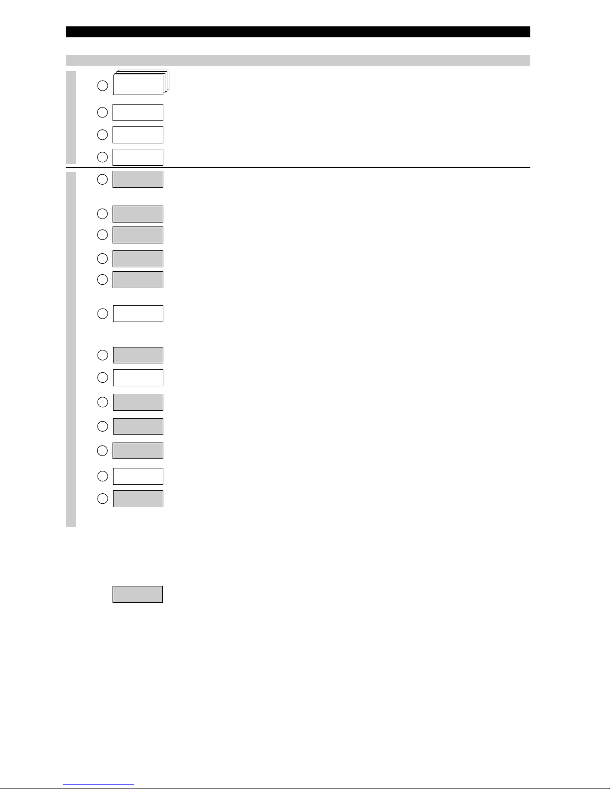
1 Calibration 2 Basic Setup 3 Advanced Setup 4 Diagnostics
5
Review
1
Device Setup 2 Level 3 % Range 4 Loop 5 Device Variables
1 Tag
2
Descriptor
3 Date
4 Message
5 Poll Address
6 Final Asmbly Num
1
Model
2 Manufacturer
3 Magnetrol S/N
4 Firmware Version
5 Tag
6 Descriptor
7 Date
8
Message
9 Poll Address
10 Final asmbly num
11 Device ID
12 Probe Model
13 Probe Mount
1
4 Measurement Type
16 Probe Length
1
5 Level Units
17 Level Offset
18 Volume Units
19 Dielectric Range
20 Sensitivity
21 PV is
22 SV is
23 TV is
24 QV is
25 4mA Set Point
26 20mA Set Point
27 Damping
28 System Fault State
29 Blocking Distance
30 SZ Fault State
31 SZ Height
32 Trim Level
33 4 mA Trim Value
34 20 mA Trim Value
35 Threshold
36 Interface Threshold
37 Fiducial Type
38 Fiducial Gain
39 Neg Threshold Ampl
40 Pos Threshold Ampl
41 Ifc Threshold Ampl
42 Compensation Mode
43 Upper Dielectric
44 7xK Correction
45 SZ Hysteresis
46 Universal rev
47 Field dev rev
48 Software rev
49 Num req preams
3
Measurement Type
4 Level Units
6 Level Offset
7 Volume Parameters
9
Sensitivity
8
Dielectric Range
10 PV is
11 Variable Selection
12 4 mA Set Point
13 20 mA Set Point
14 Damping
15 System Fault State
16 Blocking Distance
17 SZ Fault State
18 SZ Height
19 SZ Alarm Reset
20 Threshold
21 Interace Params
22 Trim Level
23 Date/Time/Initials
5 Probe Length
1
Probe Model
2 Probe Mount
1 Faults
2 Warnings
1 Loop Test
2 Present Status
3 Status History
4 Level Ticks
5 Fiducial Ticks
6 Fiducial Spread
7 Signal Strength
8 Elec Temperature
9 Interface Ticks
10 Interface Medium
11 Derating Factor
12 Target Amplitude
13 Target Ticks
1 Software Failure
2 CPU Failure
3 EEPROM Failure
4 Default Params
5 No End of Ramp
6 Loop Failure
7 Fiducial Shift
8 Slope Error
9 No Probe
10 No Fiducial
11 Safety Zone Alrm
12 No Signal
13 EOP High
14 Hi Volume Alrm
15 Lvl < Probe Length
16 EOP < Probe Length
1 Trim Loop Current
2 Enter Password
3 Fiducial Type
4 Fiducial Gain
5 Neg Threshold Ampl
6 Pos Threshold Ampl
7 Compensation
8 Factory Settings
9 SZ Hystersis
1
0 Max Temperature
11 Min Temperature
12 Reset Temperatures
13 New User Password
1 Level
2 Volume
3 IfcLvl
4 IfcVol
3 Table Length
2 Strapping Table
1 Volume Units
3 QV IS
2 TV IS
1 SV IS
3 Ifc Threshold Ampl
2 Interface Threshold
1 Upper Dielectric
1 Magnetrol S/N
2 Device ID
3 HF Cable
4 Window
5 Conversion Factor
6 Scale Offset
7 Waveform Selection
8 Factory Param 2
1 Compensation Mode
2 Upper Dielectric
3 Target Calibration
4 7xK Correction
1 Target Oper Mode
2
Target Calib Value
3
Auto Target Calib
1 Seal Leak
2 Fiducial Spread
3 Hi Temperature
4 Lo Temperature
5 Calib Required
6 EOP Too Low
7 Trim Required
8 Initializing
9 May Be Flooded
10 Dry Probe
11 Weak Signal
12 System Warning
13 Warning 1
14 Warning 2
15 No Steam Target
16 Warning 4

25
MAINTENANCE
TROUBLESHOOTING
Symptom Problem Solution
LEVEL, % OUTPUT and LOOP values
are all inaccurate.
Basic configuration data is
questionable.
Reconfigure the Probe Length «Prb Ln»
and Offset «Offset». Check also the
Probe Model «Prb Model» / Probe
Mount «Prb Mount»
1) Ensure the Level is accurate.
2) Reconfigure Loop values.
Interface level has significant emulsion. Examine process to reduce/eliminate
emulsion layer.
LEVEL readings are repeatable but
consistently high or low from actual
by a fixed amount.
Configuration data does not
accurately match probe length or tank
height.
Ensure proper probe length
«Prb Ln»
&
probe Model
«Prb Model»
.
Adjust trim level value by the amount of
noted inaccuracy.
LEVEL, % OUTPUT and LOOP
values fluctuate.
Turbulence.
I
ncrease the Damping «Damping» fac-
t
or until the readings stabilize.
High frequency connection.
Check Fiducial Spread «FidSprd»
(should be stable within ± 10 counts.)
LEVEL, % OUTPUT and LOOP
values all reading low vs. actual
(level or volume applications).
Lower dielectric material over higher
dielectric material, e.g. oil over water.
Select Fixed Threshold option «Fixed»
and/or select dielectric range from top layer.
Coating, clumping or buildup on probe. Expected inaccuracies due to affect on
pulse propagation.
Dense, water based foam. Expected inaccuracies due to affect on
pulse propagation.
LEVEL reading on Display is correct
but LOOP is stuck on 4 mA
Basic configuration data
is questionable.
Set Hart poll address «POLL ADR» to
«0». If not using HART®multi drop
HART device only: handheld will only
read Universal Commands.
Most current Device Descriptors
(DDs) are not installed in handheld.
(see page 20)
Contact local HART service center for
the latest DD’s.
LEVEL reading on display is stuck
at full scale, LOOP is stuck at 20,5 mA.
Software believes probe is flooded
(level near very top of probe).
Check actual level. If probe is not flooded, check for build up or obstructions
near top of probe. Select higher dielectric range.
Check for condensation in probe connection. Add Blocking Distance.
LEVEL, % OUTPUT and LOOP
values all at maximum level.
Possible configuration issue with single
rod probe
1) Increase Blocking Distance
2) Increase Dielectric Range
LEVEL, % OUTPUT and LOOP
values all reading high vs. actual.
Possible obstruction in tank affecting
single rod probe.
1) Increase Dielectric Range until
obstruction is ignored.
2) Relocate probe away from obstruction.
LEVEL value reading high when
should be zero.
Transmitter loose or disconnected
from probe.
Ensure transmitter connected securely
to probe.
HART ERROR MESSAGES
Error Screen Displayed status
Faults Enlists possible error messages. OFF: safe status
ON: highlighted error is occurring – see
page 27
Warnings Enlists warning messages. OFF: safe status
ON: highlighted warning is occurring –
see page 26
History Built in log of the last 26 error messages. See page 20.
PACTware™PC Program
The Eclipse Model 705 offers the ability to do Trending and Echo Curve analysis using a PACTware DTM. This is a powerful troubleshooting tool that can aid in the resolution of some of the Error Messages shown above.
Refer to Bulletins 59-101 and 59-601 for more information.
26
MAINTENANCE
Display
Message
Action Comment
OK None Normal operating mode
Initial None Program is Initializing, level
reading held at 4 mA set point.
T
his is a transient condition.
DryProbe None Normal message for a dry
probe. End of probe signal is
being detected.
WeakSgnl 1) Set transmitter to lower dielectric range
2) Increase sensitivity
Signal amplitude is lower than
desired.
Flooded? 1) Decrease level in vessel
2) Set transmitter to lower dielectric range
3) Replace with Model 7MR Overfill probe
Loss of level signal possibly
due to flooding, twin rod
probes only
Fid Sprd* 1) Check connection between probe and transmitter
2) Check for moisture on top of probe
3) Consult factory
Fiducial Ticks variation is
excessive.
Hi Temp 1) Transmitter may need to be moved to ensure ambient temperature
is within specification
2) Change to remote mount transmitter
3) Use sunshade
Present temperature in
electronics compartment is
above +80° C
Lo Temp 1) Transmitter may need to be moved to ensure ambient temperature
is within specification
2) Change to remote mount transmitter
Present temperature in
electronics compartment is
below -40° C.
Sys Warn Consult factory Unexpected but non-fatal
software event
TrimReqd Consult factory Factory set Loop values are
defaults, loop output may be
inaccurate
Cal Reqd Consult factory Factory set default calibration
parameters are in use, level
reading may be inaccurate
WARNING MESSAGES
A warning message identifies the status of the instrument. A warning message does not necessarily require immediate action but may
require close attention and/or follow up. The warning message will be displayed on the unit and/or selected on the Pactware screen while
the output signal will remain normal.

27
MAINTENANCE
D
isplay
Message
Action Comment
H
iVolAlm
V
erify strapping table is entered correctly.
L
evel more than 5% above
highest point in strapping table.
SlopeErr Consult factory Ramp circuit generating
improper voltage
LoopFail Consult factory
Note: In case of loop failure, error signal will follow the failing trend;
meaning the unit will show 3.6 mA when the reviewed loop current by
the device is found too low. The unit will show 22 mA in case the
r
eviewed loop current is found too high.
Loop current differs from
expected value
No Ramp Consult factory No End-of-Ramp signal detect-
ed
DfltParm Consult factory Internal non-volatile parameters
have been defaulted
EE Fail Consult factory EEPROM error allowing watch-
dog timer to expire
CPU Fail Consult factory A-D converter time out allowing
watchdog timer to expire
SfwrFail Consult factory A fatal software error allowing
watchdog timer to expire
EOP < Probe
Length
1) Ensure probe length is entered correctly
2) Set transmitter to a lower dielectric range
3) Set threshold to «fixed»
4) Consult factory
End of Probe signal is out of
range
Lvl < Probe
Length
1) Verify entered probe length
2) Change threshold to «fixed»
Apparent position of the upper
level pulse is lower than the
end of probe
EOP High 1) Ensure probe length is entered correctly
2) Increase blocking distance (only for single or twin GWR probes)
3) Consult factory
End of Probe signal is out of
range
NoSignal 1) Ensure dielectric setting is correct for measured medium
2) Increase sensitivity
3) Confirm that the probe type is proper for the dielectric of the medium
4) Consult factory
No level signal being detected.
No Fid 1) Check connection between probe and transmitter
2) Check for moisture on top of probe
3) Check for damaged gold pin on the high frequency connector
4) Consult factory
Fiducial signal is not being
detected
FidShift 1) Check connection between probe and transmitter
2) Check for moisture on top of probe
3) Check for damaged gold pin on the high frequency connector
4) Consult factory
FidTicks shifted from expected
value
No Probe 1) Ensure proper connection between probe and transmitter
2) Check for damaged gold pin on the high frequency connector
Electronics does not sense that
a probe is attached
SZ Alarm Decrease level in tank
When in «SZ Fault», «Latch 3.6 mA» or «Latch 22 mA» was
selected, reset with «SZ Alarm Reset»
Safety Zone alarm has been
tripped, loop current fixed at
SZ Fault
ERROR MESSAGES
An error message identifies a possible instrument failure and requires an action. The error message will be displayed on the unit and/or
selected on the Pactware screen while the output signal will shift to the selected error output (3.6mA, 22mA or HOLD).
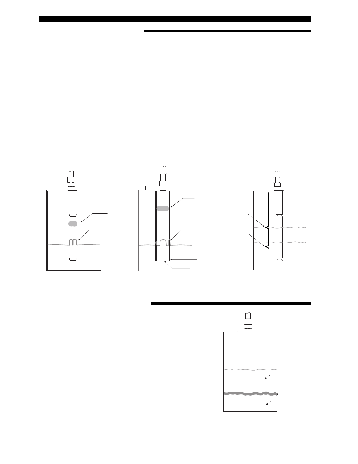
28
MAINTENANCE
TROUBLESHOOTING APPLICATIONS: Level
TROUBLESHOOTING APPLICATIONS: Interface
Most frequent application problems that may occur, media
buildup on the probe and stratification, are covered here.
M
edia buildup on the probe is not a problem in most
cases–Eclipse circuitry typically works very effectively.
Media buildup should be viewed as two types – Film
Coating and Bridging.
Recommended guidelines to select the right GWR probe:
- Relatively clean liquids: use the standard coax GWR
probes
- Possible build up: use the enlarged coax or twin rod
GWR probe
-
Extreme build up: use the single rod GWR probe
• Continuous Film Coating
The most typical of coating problems where the media
f
orms a continuous coating on the probe. Eclipse will
continue to measure effectively with some small degradation in performance. A problem can develop if the
product begins to buildup on the spacers that separate
the probe elements. High dielectric media (e.g, waterbased) will cause the greatest error.
• Bridging
Media that is viscous or solid enough to form a clog, or
b
ridge, between the elements causes the greatest
degradation in performance. High dielectric media (eg.
water-based) will show as level at the location of the
bridging.
•
Stratification/Interface
The Eclipse transmitter is designed to measure the first
air/media interface it detects, when configured for level
measurement only. It will not measure further liquid/
liquid interfaces. However, a low dielectric over a high
dielectric application can cause a measurement problem
if the level of the low dielectric medium becomes small
enough (a few cm) to cause the electronics to trigger on
the high dielectric medium that lies beneath it. Select the
F
ixed Threshold option to read the upper medium.
Example: oil over water.
F
ilm
Coating
Bridging
F
ilm
Coating
T
hreshold
«Fixed»
GOOD
T
hreshold
«CFD»
WRONG
Outer tube
Inner rod
B
ridging
Oil
ε
r 2.0
Emulsion
Layer
Air/gas
<
ε
r
>
ε
r
Water
ε
r 80
It is not uncommon for interface applications to have an
emulsion layer form between the two media. This emulsion
layer may pose problems for Guided Wave Radar as it may
decrease the strength of the reflected signal. Since the
properties of this emulsion layer are difficult to quantify,
applications with emulsion layer should be avoided with
Eclipse.
Continuous film coating / Bridging Stratification/Interface
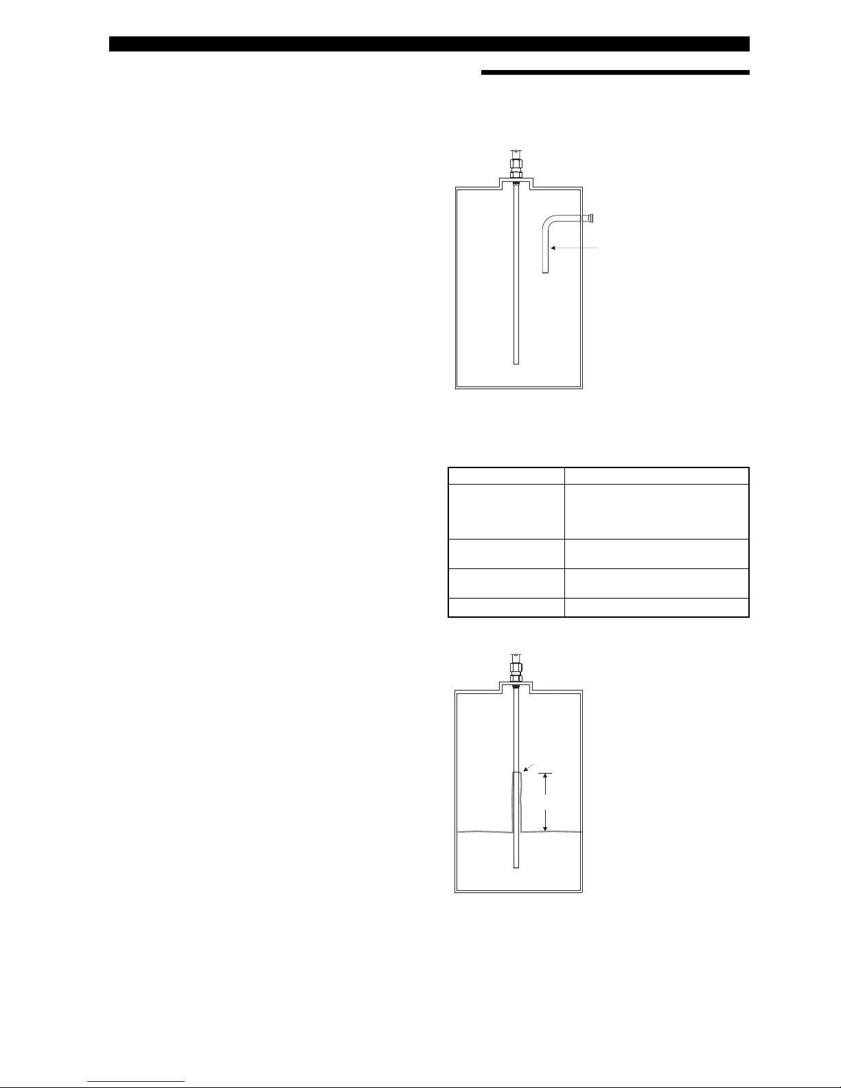
29
MAINTENANCE
TROUBLESHOOTING APPLICATIONS: Single Rod type GWR probe
Most frequent application problems that may occur, media
buildup on the probe and stratification, are covered here.
S
ignificant buildup on the probe is not a problem in most
cases–Eclipse circuitry typically works very effectively.
• Nozzles (only for 7MF/7MH/7MJ/7M1/7M2)
Nozzles can create false echoes that can cause diagn
ostic messages and/or errors in measurement. If end
of probe high «Eop High» is displayed when first configuring the instrument:
1. Ensure the probe length «Prb Ln» as entered in the
software is equal to the actual probe length (see page
12, item 9). This value must be changed if the probe
is cut shorter from the original length.
2. Increase the blocking distance «BlockDis» value
until the message is eliminated; 20 mA point may
n
eed to be lowered.
3. Increase the dielectric range a small amount or
decrease the sensitivity to aid in reducing echoes in
nozzle. Increasing the dielectric settings may cause
instrument to lose level of lower dielectric media; consult factory.
• Obstructions (only for 7MF/7MH/7MJ/7M1/7M2)
If the level reading repeatedly locks on to a specific level
higher than the current level, it may be caused by a
metallic obstruction. Obstructions in the vessel (e.g.
pipes, ladders) that are located close to the probe may
cause the instrument to show them as level.
1. Refer to the Probe Clearance Table
2. Increase the dielectric range a small amount or
decrease the sensitivity to aid in reducing disturbing
echoes in nozzle. Increasing the dielectric settings
may cause instrument to lose level of lower dielectric
media; consult factory.
• Coating/build-up (only for 7MF/7MH/7MJ/7M1/7M2)
The Eclipse
®
705 wih Single Rod Probe was designed to
operate effectively in the presence of media building up.
Some expected error may be generated based upon the
following factors:
¨ Dielectric of the media that created the coating
≠ Thickness of the coating
Æ Length of the coating above the present level
In case build up is picked up as level, increase the
dielectric range a small amount or decrease the sensitivity.
• Coating/build-up (only for 7M5/7M7)
Continuous film coating is where the media forms a thin
continuous coating on the probe. Eclipse
®
will continue
to measure effectively with some degradation in performance. The degradation is proportional to the dielectric
of the media and the thickness of the coating up to a
degree that the unit will see coating as a level. Higher
dielectric media (eg. water based) will show sooner as a
level at the location of the build up.
¨
≠
Æ
O
bstruction
Nozzles
• 2" diameter minimum
• Ratio of diameter: length should be > 1:1
If not, set blocking distance at 2 x nozzle height
• Do not use pipe reducers (restriction)
Coating Build-up
Distance to probe
Acceptable objects
< 150 mm (6") Continuous, smooth, parallel,
conductive surface (e.g. metal
tank wall);
probe should not touch
tank wall
> 150 mm (6") < 1"/DN25 diameter pipe and
beams, ladder rungs
> 300 mm (12") < 3"/DN80 diameter pipe and
beams, concrete walls
> 450 mm (18") All remaining objects
Probe clearance table
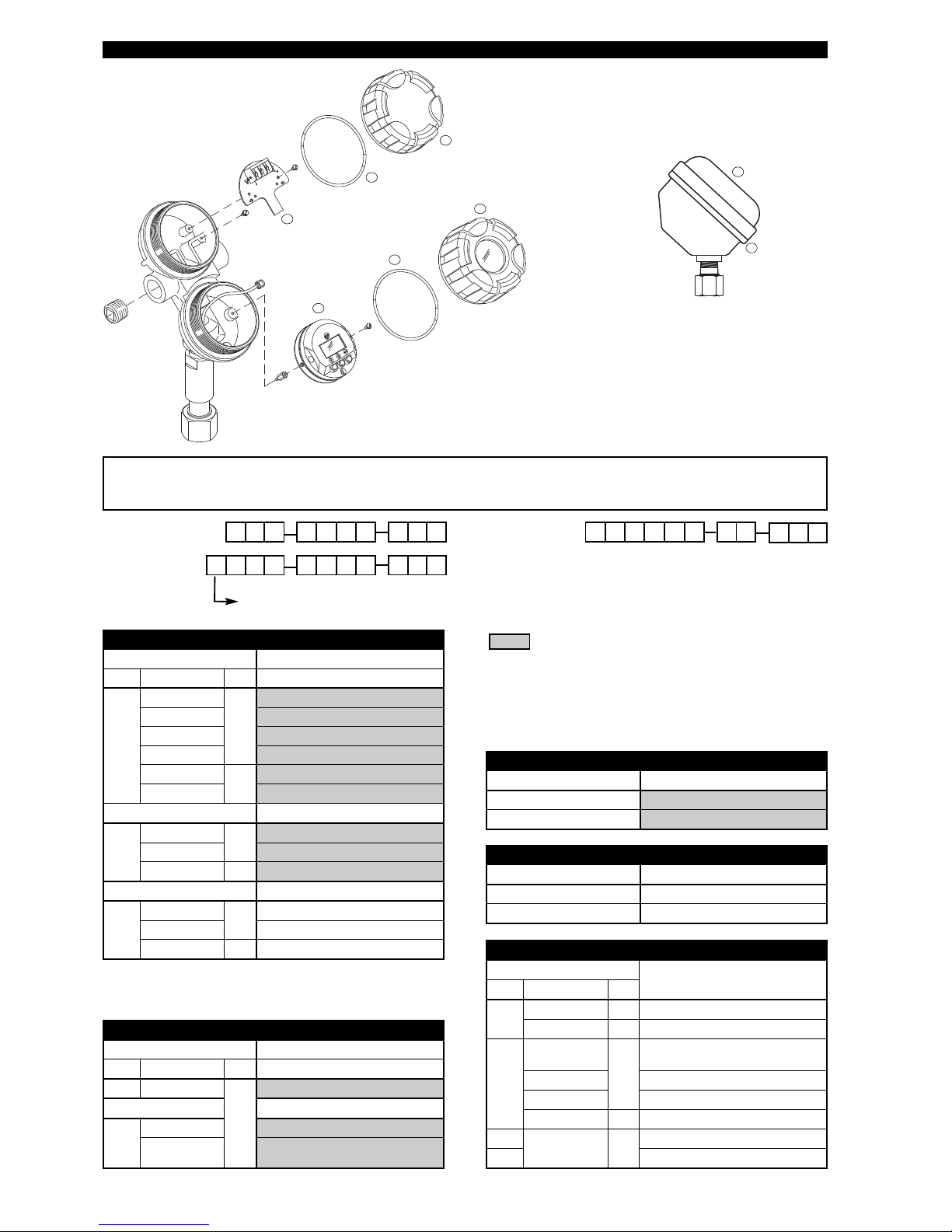
30
REPLACEMENT PARTS
1
2
3
4
3
5
5
3
CAUTION: the electronic module connects to the antenna via the “High frequency connector”. This part is
extremely sensitive and brittle and requires to be handled very careful. It is recommended to exchange complete
amplifier heads instead of electronic modules in the field.
1X742 3 8 9 105
6
Digit in partn°:
750 5
Partn°:
X = product with a specific customer requirement
Electronic Module (1)
Digits Replacement part
5 6 & 7 9 Hart
1
00
1, 2,
7 or
8
Z31-2835-002
0A Z31-2835-001
A0 Z31-2835-004
AA Z31-2835-003
00 or 0A
3 or
9
089-7254-001
A0 or AA 089-7254-003
FF
2
00
1, 2,
7 or 8
Z31-2841-002
0A Z31-2841-001
00 or 0A
3 or 9
089-7254-002
Profibus PA
3
00
1, 2,
7 or 8
Z31-2846-002
0A Z31-2846-001
00 or 0A
3 or 9
089-7254-004
Wiring board (2)
Digits Replacement part
5 8 9 Hart
1 all
1, 2,
7 or 8
Z30-9151-001
FF - Profibus PA
2
or
3
1, 2, A or B Z30-9151-004
3, 4, C, D, E,
or F
Z30-9151-003
Housing cover (5)
Digits
Replacement part
7 8 9
0
all
1 or 7
004-9225-002
all
2 or 8
004-9225-003
A
1, 2, A, B, E
or F
1 or
7
036-4413-005
3 or 4 036-4413-001
C or D 036-4410-003
all
2 or 8
036-4413-012
0
all
3 or
9
032-3934-001
A 036-5702-002
Housing “O” ring (3)
Digit 9 Replacement part
1, 2, 7 or 8 012-2201-237
3 or 9 012-2201-155
Housing cover (4)
Digit 9 Replacement part
1 or 7 004-9225-002
2 or 8 004-9225-003
Industrial
Hygienic
Serial n°:
See nameplate, always provide complete partn° and
serial n° when ordering spares.
E X P E D I T E S H I P P L A N ( E S P )
Several parts are available for quick shipment, within max.
1 week after factory receipt of purchase order, through the
Expedite Ship Plan (ESP).
Parts covered by ESP service are conveniently grey coded
in the selection tables.

31
REPLACEMENT PARTS
1
1
8
9
8
9
8
9
7
6
10
10
12
9
Cable weight
7M1 Single flexible cable
7M7 Dual flexible cable
Bottom spacer
- 7MF/7MJ single rod
G
WR probe
- 7MG cage GWR probe
(2"/DN50)
Cable weight
7M2 Single flexible cable
for solids
Spacer 7MB
Twin rod
C
able weight
7M5 dual flexible cable
for solids
6
Bottom spacer
- 7MG cage GWR probe
(other than 2"/DN50)
1
3
Spacer and set pin - rigid probes
N° Description Replacement part
TFE spacer & set pin
6 & 7
7MF-A 089-9114-001
7MF-B 089-9114-002
7MF-C 089-9114-003
PEEK spacer & set pin
6 & 7
7MJ-A 089-9114-005
7MJ-B 089-9114-006
7MJ-C 089-9114-007
Spacer and set pin - cage probes
N° Description Replacement part
6 & 7
7MG-A (2"/DN50) 089-9114-001
7MG-B (2"/DN50) 089-9114-002
7MG-C (2"/DN50) 089-9114-003
6
7MG (other than
2"/DN50)
consult factory
Cable weights - flexible probes
N° Description Replacement part
8 7M1 089-9120-001
9 7M7 089-9121-001
10
7M2/7M5
cable rope clip
010-1731-001
(Qty 2 required)
11 7M2-316 (1.4401) 004-8778-001
12 7M5-316 (1.4401) 004-8778-002
Spacer - twin rod probe
N° Description Replacement part
13
7MB probe spacer
kit
consult factory

32
TRANSMITTER SPECIFICATIONS
FUNCTIONAL/PHYSICAL
¿
Foundation Fieldbus™ and Profibus PA™ units.
¡
For ATEX flameproof enclosure units use Ex d bushing material STYCAST 2057 FR.
¬
Not applicable for Foundation Fieldbus™ and Profibus PA™ units.
Description Specification
Power (at terminals) HART®:
- Weatherproof / ATEX flameproof enclosure / ATEX non sparking: 11 to 36 V DC
- ATEX Intrinsically Safe: 11 to 28,4 V DC
Foundation Fieldbus™ / Profibus PA™:
- Weatherproof / ATEX flameproof enclosure / ATEX FNICO: 9 to 32 V DC
- ATEX FISCO: 9 to 17,5 V DC
Output 4-20 mA with HART®, 3,8 mA to 20,5 mA useable (meets NAMUR NE 43) – HART 6,
Foundation Fieldbus™ H1 or Profibus PA™ H1
Span 15 cm to 22 m (6" to 72.18') depending on selected probe
Resolution Analog: 0,01 mA
Display: 0,1 (cm or inch)
Loop Resistance 630 Ω @ 20,5 mA - 24 V DC
Damping Adjustable 0-10 s
Diagnostic Alarm Adjustable 3,6 mA, 22 mA, HOLD last output
User Interface HART®communicator, AMS®or PACTware™, Foundation Fieldbus™, Profibus PA™
and/or 3-button keypad
Display 2-line x 8-character LCD
Menu Language English/Spanish/French/German (Foundation Fieldbus™, Profibus PA™: English)
Housing Material IP 66/Aluminium A356T6 (< 0.20 % copper) or stainless steel
Approvals ATEX II 3 (1) G EEx nA [ia] IIC T6, non sparking
(probe can be used in flammable liquids)
ATEX II 3 (1) G EEx nA [nL][ia] IIC T6, FNICO – non incendive¿(probe can be used in
flammable liquids)
ATEX II 1 G Ex ia IIC T4 Ga, intrinsically safe
ATEX II 1 G Ex ia IIC T4 Ga, FISCO – intrinsically safe
¿
ATEX
II 1/2 G Ex d[ia Ga] IIC T6 Gb
¡
ATEX
II 1/2 D Ex t[ia Da] IIIC T85°C Db IP66
¡
IEC
Ex d[ia Ga] IIC T6 Gb
IEC
Ex t[ia Da] IIIC T85°C Db IP66
IEC Ex ia IIC T4 Ga, intrinsically safe
IEC Ex ia IIC T4 Ga, FISCO – intrinsically safe
¿
IEC Ex ic[ia Ga] IIC T4 Gc
EN 12952-11 and EN 12953-9 CE approved for steam drums as primary level safety
device
TÜV – WHG § 63, VLAREM II 5.17-7
LRS – Lloyds Register of Shipping (marine applications)
Other approvals are available, consult factory for more details
SIL
¬
(Safety Integrity Level)
Standard
electronics
Functional safety to SIL 1 as 1oo1 / SIL 2 as 1oo2 in accordance to IEC 61508 – SFF of
84,5 %
Enhanced
electronics
Functional safety to SIL 2 as 1oo1 in accordance to IEC 61508 – SFF of 91 %
Certified for use in SIL 3 loops.
Electrical Data Ui = 28,4 V, li = 124 mA, Pi = 0,84 W (HART®)
Ui = 17,5 V, li = 380 mA, Pi = 5,32 W (Foundation Fieldbus™ / Profibus PA™)
Equivalent Data Ci = 2,2 nF, Li = 3 µH (HART®)
Ci = 3 nF, Li = 3 µH (Foundation Fieldbus™ / Profibus PA™)
Shock/Vibration Class ANSI/ISA-S71.03 Class SA1 (Shock), ANSI/ISA-S71.03 Class VC2 (Vibration)
Surge protection Meets CE EN 61326 (1000V)
Net weight Cast aluminium 2,7 kg (6.0 lbs) – transmitter head / electronics only
Stainless steel 5,7 kg (12.6 lbs) – transmitter head / electronics only
Overall Dimensions H 214 mm (8.43") x W 111 mm (4.38") x D 188 mm (7.40")
Foundation Fieldbus™
specifications
ITK Version 5.0
H1 Device Class Link Master (LAS) – selectable ON/OFF
Function Blocks 1 x RB, 4 x AI, 1 x TB and 1 x PID
Execution time AI = 15 ms, PID = 40 ms
Quiescent current draw
15 mA
DD/CFF files Available at www.fieldbus.org
Profibus PA
specifications
Device revision 0x01
Digital communication
protocols
Version 3.0 MBP (31.25 kbits/sec)
Function Blocks 1 x PB, 4 x Al blocks, 1 x TB
Execution time 15 ms
Quiescent current draw
15 mA
GSD files Available at www.profibus.com

33
TRANSMITTER SPECIFICATIONS
PERFORMANCE
Description Specification
Reference Conditions with a 1,8 m (72")
coaxial type GWR probe
Reflection from liquid, with dielectric in center of selected range, at +20 °C (70 °F) with
CFD threshold
¿
Linearity
¡
Coaxial/twin lead probes < 0,1 % of probe length or 2,5 mm (0.1"), whichever is greater
Single lead probes < 0,3 % of probe length or 8 mm (0.3"), whichever is greater
Accuracy
¡
Coaxial/twin lead probes < 0,1 % of probe length or 2,5 mm (0.1"), whichever is greater
Single lead probes ± 0,5 % of probe length or 13 mm (0.5"), whichever is greater
7MT/7ML interface ± 25 mm (1")
Resolution ± 2,5 mm (0.1")
Repeatability < 2,5 mm (0.1")
Hysteresis < 2,5 mm (0.1")
Response Time < 1 second
Warm-up Time < 5 seconds
Ambient Temp. -40 °C to +80 °C (-40 °F to +175 °F) – blind transmitter
-20 °C to +70 °C (-5 °F to +160 °F) – with digital display
-40 °C to +70 °C (-40 °F to +160 °F) – for Ex ia and Ex d[ia] with blind transmitter
-20 °C to +70 °C (-5 °F to +160 °F) – for Ex ia and Ex d[ia] with digital display
Process Dielectric Effect < 7,5 mm (0.3") within selected range
Operating Temp. Effect
Approx. +0,02 % of probe length/°C for probes ≥ 2,5 m (8')
¬
Humidity 0-99 %, non-condensing
Electromagnetic Compatibility Meets CE requirements (EN 61326: 1997 + A1 + A2) and NAMUR NE 21
(Single and Twin-Rod probe must be used in metallic vessel or stillwell)
¿
May degrade for 7MD/7ML probe or with fixed threshold.
¡
Top 600 mm (24") of twin rod probe: 30 mm (1.18").
Top 1220 mm (48") of single rod: application dependant.
Accuracy may degrade when using compensation.
¬
Accuracy may degrade slightly < 2,5 m (8')

34
PROBE SPECIFICATIONS
¿
Transition Zone (zone with reduced accuracy) is dielectric dependent; εr = dielectric permitivity.
It is recommended to set 4-20 mA signal outside transition zone.
¡
See graphs at page 39 and 40.
Description 7MR/7MM: overfill protection coaxial probe
Materials Probe 316/316L (1.4401/1.4404), Hastelloy®C (2.4819) or Monel®(2.4360)
Process seal Teflon®with Viton®GFLT, Aegis PF 128 or Kalrez®4079 (consult factory for alternatives)
Spacers Teflon
®
Probe diameter Small coax Inside rod 8 mm (0.315") – outer tube 22,5 mm (0.88")
Enlarged Stainless steel: inside rod 16 mm (0,63") – outer tube 45 mm (1.75")
Hast. C / Monel®: inside rod 16 mm (0,63") – outer tube 49 mm (1.93")
Mounting External cage and/or in-tank mounting
Process Connection Small coax Threaded: 3/4" NPT or 1" BSP (G 1")
All Flanged: various ANSI, EN (DIN) or torque tube mating flanges
Probe length From 60 cm to 610 cm (24" to 240")
Transition Zone
¿
Top 0 mm (0")
Bottom
εr: 1,4 = 150 mm (6")/εr: 80 = 25 mm (1")
Process Temp.
¡
Max +200 °C @ 18,6 bar (+400 °F @ 270 psi)
Min -40 °C @ 51,7 bar (-40 °F @ 750 psi)
Max. Process Pressure
¡
70 bar @ +20 °C (1000 psi @ +70 °F)
Max. Viscosity Small coax: 500 mPa.s (cP); Enlarged coax: 2000 mPa.s (cP)
Dielectric Range
1,4 to 100
Vacuum Service
Negative pressure but not hermetic seal
Media coating
In case of media coating, select 7MM probe
IntDescription 7MD/7ML: high pressure / high temperature GWR probe
Materials Probe 316/316L (1.4401/1.4404), Hastelloy®C (2.4819) or Monel®(2.4360)
Process seal Borosilicate / Inconel®X-750
Spacers 7Mx-A, B and C: Ceramic
7Mx-W: Teflon
®
7Mx-V: High Temp PEEK
7Mx-N, P and R: PEEK
Probe diameter Small coax Inside rod 8 mm (0.315) – outer tube 22,5 mm (0,88")
Enlarged Stainless steel: inside rod 16 mm (0,63") – outer tube 45 mm (1.75")
Hast. C / Monel®: inside rod 16 mm (0,63") – outer tube 49 mm (1.93")
Mounting External cage and/or in-tank mounting
Process Connection Small coax Threaded: 3/4" NPT or 1" BSP (G 1")
All Flanged: various ANSI, EN (DIN) or torque tube mating flanges
Probe length From 60 cm to 610 cm (24" to 240")
Transition Zone
¿
Top 0 mm (0")
Bottom
εr: 1,4 = 150 mm (6") / εr: 80 = 25 mm (1")
Process Temp.
¡
Max +425 °C @ 103 bar (+800 °F @ 1500 psi) for 7Mx-A, B and C
+345 °C @ 324 bar (+650 °F @ 4700 psi) for 7Mx-V, N, P and R
+200 °C @ 393 bar (+400 °F @ 5700 psi) for 7Mx-W
Min
-196 °C @ 138 bar (-320 °F @ 2000 psi)
Max. Process Pressure
¡
431 bar @ +20 °C (6250 psi @ +70 °F)
Max. Viscosity Small coax: 500 mPa.s (cP); Enlarged coax: 2000 mPa.s (cP)
Dielectric Range Small coax 1,4 to 100 for 7Mx-W
1,7 to 100 for 7Mx-V
2,0 to 100 for 7Mx-A, B and C
Enlarged
Level: Probes ≤ 2,5 m: εr ≥ 1,4 with single bottom spacer
Probes > 2,5 m: εr ≥ 1,7
Interface: Upper liquid: εr ≥ 1,4 or 1,7 (see above) and ≤ 5
Lower liquid: εr ≥ 15
Vacuum service
Full vacuum
(Helium leak < 10-8cc/s @ 1 atmosphere vacu
um)
Media coating In case of media coating, select 7ML probe

35
PROBE SPECIFICATIONS
¿
Transition Zone (zone with reduced accuracy) is dielectric dependent; εr = dielectric permitivity.
It is recommended to set 4-20 mA signal outside transition zone / blocking distance.
¡
See graphs at page 39 and 40.
Description 7MF (industrial): standard single rod 7MJ: HTHP single rod
Materials
Probe
316/316L (1.4401/1.4404), Hastelloy®C (2.4819),
Monel
®
(2.4360), or PFA insulated 316/316L
(1.4401/1.4404)
316/316L (1.4401/1.4404), Hastelloy®C (2.4819)
or Monel
®
(2.4360)
Process seal
TFE with Viton®GFLT, Aegis PF 128 or Kalrez
®
4079 (consult factory for alternatives)
PEEK with Aegis PF 128
Probe diameter
Bare: 13 mm (0.50") PFA coated: 16 mm (0.625")
Bare: 13 mm (0.50")
Process Connection
Threaded: 2" NPT or 2" BSP (G 2")
Flanged: various ANSI or EN (DIN) flanges
Probe length From 60 cm to 610 cm (24" to 240")
Blocking distance (top) 120 mm up to 910 mm (4.8" up to 36") - depending probe length (adjustable)
Transition Zone¿(bottom)
εr ≥ 10: 25 mm (1")
Process Temp.
¡
Max +150 °C @ 27,6 bar (+300 °F @ 400 psi) +315 °C @ 155 bar (+600 °F @ 2250 psi)
Min 7MF-F: -40 °C @ 13,8 bar (-40 °F @ 200 psi)
Other 7MF-probes: -40 °C @ 51,7 bar (-40 °F @
750 psi)
-15 °C @ 245 bar (0 °F @ 3550 psi)
Max Process Pressure
¡
70 bar @ +20 °C (1000 psi @ +70 °F) 245 bar @ +20 °C (3550 psi @ +70 °F)
Max Viscosity 10.000 mPa.s (cP) – consult factory in case of agitation/turbulence
Dielectric Range
εr: 10-100 (depending installation conditions, down to εr ≥ 1,9)
Vacuum service Negative pressure but not hermetic seal
Media coating
Max error of 10 % of coated length. % Error is related to dielectric of medium, thickness of coating and
coated probe length above level.
Description 7MS: saturated steam GWR probe 7MQ: saturated steam GWR probe
Materials Probe 316/316L (1.4401/1.4404)
Process seal High Temp PEEK with Aegis PF 128 High Temp PEEK with Aegis PF 128
Alumina
Spacers High Temp PEEK Silicon nitride
Probe diameter Inside rod 8 mm (0.315) –
outer tube 22,5 mm (0,88")
Inside rod 8 mm (0.315) –
outer tube 32 mm (1,25")
Mounting External cage and/or in-tank mounting
Process Connection Threaded: 3/4" NPT or 1" BSP (G 1")
Flanged: various ANSI, EN (DIN) or torque
tube mating flanges
Threaded: not available
Flanged: various ANSI, EN (DIN) or torque
tube mating flanges
Probe length From 60 cm to 450 cm (24" to 177")
Transition Zone
¿
Top 200 mm (8"); consult factory for overfill applications
Bottom
εr ≥ 10 = 25 mm (1")
Process Temp.
¡
Max +300 °C @ 88 bar (+575 °F @ 1275 psi) +345 °C @ 155 bar (+650 °F @ 2250 psi)
Min
-15 °C @ 207 bar (0 °F @ 3000 psi)
Max. Process Pressure
¡
88 bar @ +300 °C (1275 psi @ +575 °F) 155 bar @ +345 °C (2250 psi @ +650 °F)
Max. Viscosity 500 mPa.s (cP)
Dielectric Range 10 to 100
Vacuum service Negative pressure but not hermetic seal
Media coating Not applicable

36
PROBE SPECIFICATIONS
¿
Transition Zone (zone with reduced accuracy) is dielectric dependent; εr = dielectric permitivity.
It is recommended to set 4-20 mA signal outside transition zone / blocking distance.
¡
See graphs at page 39 and 40.
Description 7M1 (liquids) / 7M2 (solids): single flexible 7M5 (solids) /7M7 (liquids): twin flexible
Materials
Probe
316 SST (1.4401) FEP coated 316 SST (1.4401)
Process seal
7M1/7M7: Teflon®with Viton®GFLT, Aegis PF 128 or Kalrez®4079 (consult factory for alternatives)
7M2/7M5: Teflon®with Viton®GFLT
Probe diameter
7M1: 5 mm (0.19")
7M2: 6 mm (0.25")
6 mm (0.25")
Process Connection
Threaded: 2" NPT or 2" BSP (G 2")
Flanged: various ANSI or EN (DIN) flanges
Probe length From 2 m (6.56') to max 22 m (72.18')
Blocking distance (top)
120 mm up to 910 mm (4.8" up to 36") - depending
probe length (adjustable)
300 mm to 500 mm (12" to 20")
Transition Zone¿(bottom)
305 mm (12")
Process Temp.
¡
Max
7M1/7M7: +150 °C @ 27,6 bar (+300 °F @ 400 psi)
7M2/7M5: +65 °C @ 3,45 bar (+150 °F @ 50 psi)
Min
7M1/7M7: -40 °C @ 51,7 bar (-40 °F @ 750 psi)
7M2/7M5: -40 °C @ 3,45 bar (-40 °F @ 50 psi)
Max Process Pressure
¡
7M1/7M7: 70 bar @ +20 °C (1000 psi @ +70 °F)
7M2/7M5: 3,45 bar @ +20 °C (50 psi @ +70 °F)
Max Viscosity
10.000 mPa.s (cP) – consult factory in case of
agitation/ turbulence
1500 mPa.s (cP)
Dielectric Range
7M1:
εr: 10-100 (depending installation conditions,
down to εr ≥ 1,9)
7M2:
εr: 4-100
εr: 1,9-100
Mechanical load 7M1: 9 kg (20 lbs)
Pull-down force 7M2: 1360 kg (3000 lbs) 7M5: 1360 kg (3000 lbs)
Vacuum service Negative pressure but not hermetic seal
Media coating
Max error of 10 % of coated length. % Error is related to dielectric of medium, thickness of coating and
coated probe length above level.
Description 7MF-E/G/H & 7MH: hygienic single rod probe
Materials
Probe
316/316L (1.4401/1.4404), Hastelloy®C22 (2.4602) or AL-6XN stainless steel (UNS N08367); 7MH
also available in 316L (1.4435) stainless steel
Process seal
7MF: PTFE (GRAS 21CFR177-1550 and USP <88> Class VI at 121 °C)
7MH: PEEK & 'O'-ring in Viton or EPDM (GRAS 21CFR177-1550 and USP <88> Class VI at 121 °C)
Probe diameter 13 mm (0.50") or 6 mm (0.25")
Probe length From 30 cm to 610 cm (12" to 240") (selectable per 1 cm)
Blocking distance (top) 0 mm up to 910 mm (0" up to 36") - depending probe length (adjustable)
Transition Zone➀(bottom)
εr ≥ 10: 25 mm (1")
Process Temp.
¡
Max
+150 °C @ 13,8 bar (+300 °F @ 200 psi) for 7MH with Viton GF ‘O’-rings and 7MF
+120 °C @ 13,8 bar (+250 °F @ 200 psi)
for 7MH with EPDM ‘O’-rings
Min -40 °C @ 13,8 bar (-40 °F @ 200 psi)
Max Process Pressure
¡
13,8 bar @ +150 °C (200 psi @ +300 °F)
for 7MH with Viton GF ‘O’-rings and 7MF
13, 8 bar @ +120 °C (200 psi @ +250 °F) for 7MH with EPDM ‘O’-rings
Max Viscosity 10.000 mPa.s (cP) – consult factory in case of agitation/turbulence
Dielectric Range
εr 10-100 (depending installation conditions, down to εr ≥ 1,9) – liquids
Media coating
Max error of 10 % of coated length. % Error is related to dielectric of medium, thickness of coating and
coated probe length above level.
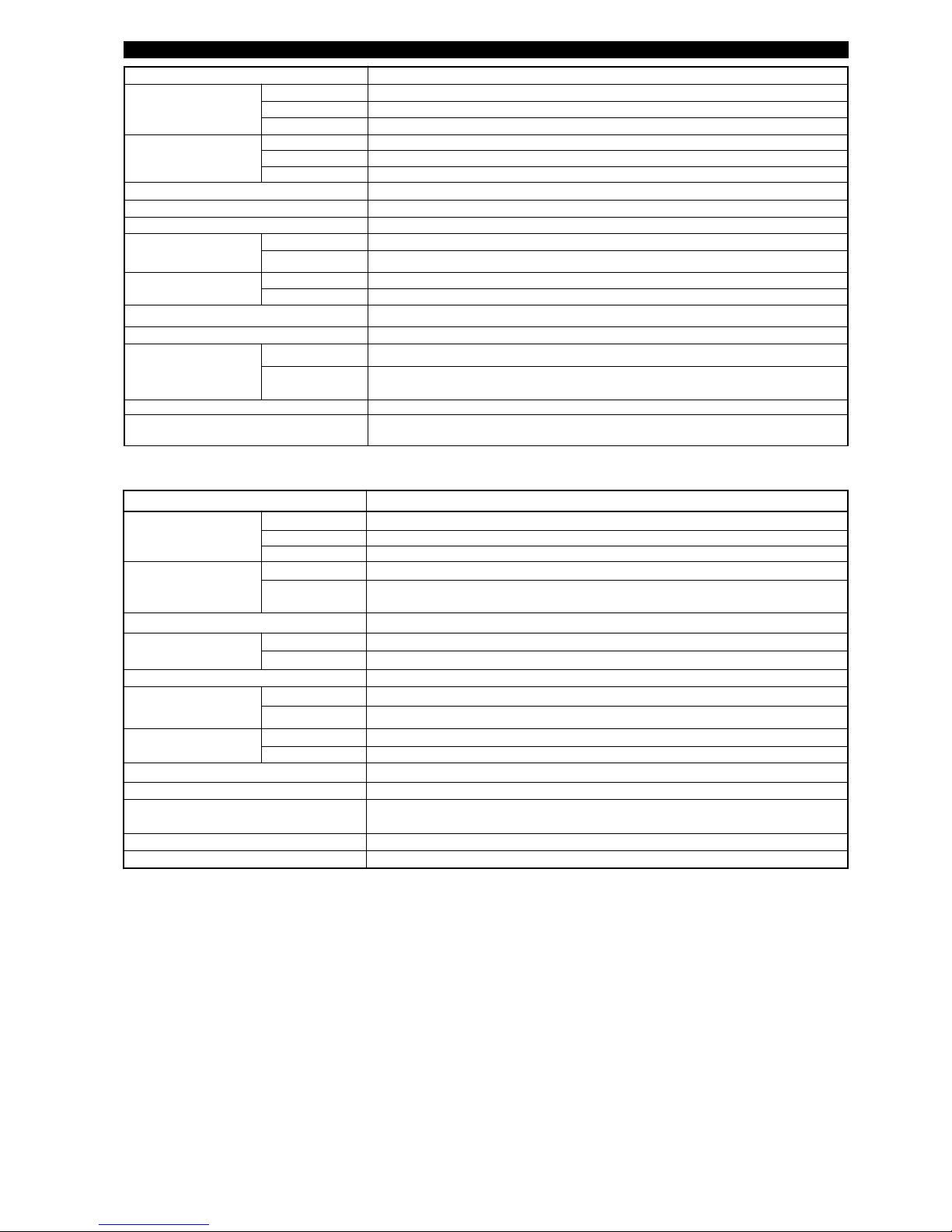
37
PROBE SPECIFICATIONS
Description 7MT/7MN: interface GWR probe
Materials Probe 316/316L (1.4401/1.4404), Hastelloy®C (2.4819) or Monel®(2.4360)
Process seal Teflon®with Viton®GFLT, Aegis PF 128 or Kalrez®4079
(consult factory for alternatives)
Spacers Teflon
®
Probe diameter Small coax inside rod 8 mm (0.315") – outer tube 22,5 mm (0.88")
Enlarged Stainless steel: inside rod 16 mm (0.63") – outer tube 45 mm (1.75")
Hast. C / Monel®: inside rod 16 mm (0.63") – outer tube 49 mm (1.93")
Mounting External cage and/or in-tank mounting
Process Connection Small coax Threaded: 3/4" NPT or 1" BSP (G 1")
all Flanged: various ANSI, EN (DIN) or torque tube mating flanges
Probe length From 60 cm to 610 cm (24" to 240")
Transition Zone
¿
Top 0 mm (0")
Bottom
εr: 1,4 = 150 mm (6")/εr: 80 = 50 mm (2")
Process Temp.
¡
Max +200 °C @ 18,6 bar (+400 °F @ 270 psi)
Min
-40 °C @ 51,7 bar (-40 °F @ 750 psi)
Max. Process Pressure
¡
70 bar @ +20 °C (1000 psi @ +70 °F)
Max. Viscosity Small coax: 500 mPa.s (cP); Enlarged coax: 2000 mPa.s (cP)
Dielectric Range
Upper liquid:
εr
≥ 1,4 and ≤ 5
Lower liquid:
εr
≥ 15
Vacuum service
Negative pressure but not hermetic seal
Media coating In case of media coating, select 7MN probe
Description 7MG: cage GWR probe
Materials Probe 316/316L (1.4401/1.4404), Hastelloy®C (2.4819) or Monel®(2.4360)
Process seal Teflon®with Viton®GFLT, Aegis PF 128 or Kalrez®4079 (consult factory for alternatives)
Bottom spacer 2" cage: Teflon®; 3" and 4" cage: PEEK
Probe diameter 2" cage 13 mm (0.50")
3" cage 19 mm (0.75")
4" cage 25 mm (1")
Mounting In a 2", 3" or 4" cage / schedule pipe stillwell or bridle
Process Connection Flanged: various ANSI or EN (DIN) flanges
Probe length From 60 cm to 610 cm (24" to 240")
Transition Zone
¿
Top 0 mm (0")
Bottom
εr: 1,4 = 150 mm (6")/εr: 80 = 50 mm (2")
Process Temp.
¡
Max +200 °C @ 18,6 bar (+400 °F @ 270 psi)
Min -40 °C @ 51,7 bar (-40 °F @ 750 psi)
Max. Process Pressure
¡
70 bar @ +20 °C (1000 psi @ +70 °F)
Max. Viscosity 10.000 mPa.s (cP)
Dielectric Range
Level
εr ≥ 1,4
Interface
Upper liquid: εr ≥ 1,4 and ≤ 5
Lower liquid: εr ≥ 15
Vacuum Service
Negative pressure but not hermetic seal
Media coating Max error of 10 % of coated length. % Error is related to dielectric of medium, thickness of
coating and coated probe length above level.
¿
Transition Zone (zone with reduced accuracy) is dielectric dependent; εr = dielectric permitivity.
It is recommended to set 4-20 mA signal outside transition zones.
¡
See graphs at page 39 and 40.
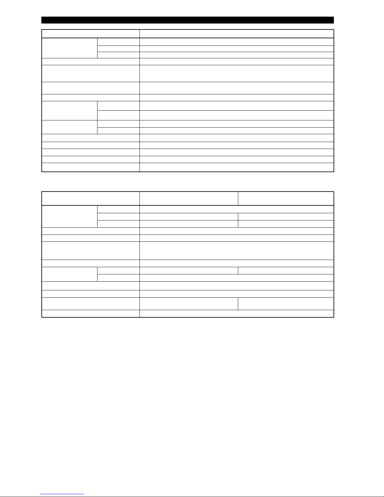
38
Description 7MB: standard twin rod GWR probe
Materials Probe 316/316L (1.4401/1.4404), Hastelloy®C (2.4819) or Monel®(2.4360)
Process seal Teflon®with Viton®GFLT, Aegis PF 128 or Kalrez®4079
(consult factory for alternatives)
Spacers Teflon
®
Probe diameter Two 13 mm (0.5") Ø rods – 22,2 mm (0.875")
C
L
to
C
L
Mounting In-tank mounting only.
Twin rod probe must be used in metallic vessel or stillwell
> 25 mm (1") from any surface or
obstruction.
Process Connection Threaded: 2" NPT or 2" BSP (G 2")
Flanged: various ANSI, EN (DIN) or
torque tube mating flanges
Probe length From 60 cm to 610 cm (24" to 240")
Transition Zone
¿
Top
εr ≥ 1,9 = 150 mm (6")
Bottom
εr: 1,9 = 150 mm (6")/εr: 80 = 25 mm (1")
Process Temp.
¡
Max +150 °C @ 27,6 bar (+300 °F @ 400 psi)
Min
-40 °C @ 51,7 bar (-40 °F @ 750 psi)
Max. Process Pressure
¡
70 bar @ +20 °C (1000 psi @ +70 °F)
Max. Viscosity 1500 mPa.s (cP)
Dielectric Range 1,9 to 100
Vacuum service
Negative pressure but not hermetic seal
Media coating
Film: 3% error of coated length, bridging not recommended
Æ
PROBE SPECIFICATIONS
¿
Transition Zone (zone with reduced accuracy) is dielectric dependent;
εr = dielectric permitivity. It is recommended to set 4-20 mA signal out-
side transition zones.
¡
See graphs at page 39 and 40.
Æ
Bridging is defined as continuous accumulation of material between the
probe elements.
Description 7EK: Top/Bottom GWR probe
ε
r ≥ 1,4 - max +260 °C
7EK: Top/Bottom GWR probe
ε
r ≥ 10 - max +315 °C
Materials Probe 316/316L (1.4401/1.4404)
Process seal PEEK and TFE with Aegis PF 128 PEEK and Alumina with Aegis PF 128
Bottom spacer TFE PEEK
Probe diameter Inside tube: max 22,5 mm (0.88")
Cage 2" - Sch 80 Top/Bottom cage
Process Connection Threaded: 1 1/2" NPT or 2" NPT
Welded: 1 1/2" or 2" socket weld
Flanged: Various ANSI, EN (DIN) or torque tube mating flanges
Measuring range min 356 mm (14") Std. – max 6,1 m (240")
Process Temp.
¡
Max +260 °C @ 115 bar (+500 °F @ 1670 psi) +315 °C @ 109 bar (+600 °F @ 1585 psi)
Min
-15 °C @ 117 bar (0 °F @ 1700 psi)
Max. Process Pressure
¡
117 bar @ -15 °C (1700 psi @ +0 °F)
Max. Viscosity 10.000 mPa.s (cP)
Dielectric Range (level only) 1,4 to 100 - Non conductive and conductive
media
10 to 100 - Conductive media
Vacuum service
Negative pressure but not hermetic seal

39
TEMPERATURE - PRESSURE RATING FOR ECLIPSE PROBE SEAL
Process temperature (°C)
Process pressure (bar)
Process temperature (°C)
Process pressure (bar)
7MR/7MM, 7MT/7MN, 7MG probes
7MD/7ML probes
small coax
P
rocess temperature (°C)
Process pressure (bar)
Process temperature (°C)
Process pressure (bar)
7M1/7M7, 7MB, 7MF probes
except 7MF-E, F, G, H
7MF-F probes
Process temperature (°C)
Process pressure (bar)
7MD/7ML probes
enlarged coax
Process temperature (°C)
Process pressure (bar)
7MF-E, G, H probes
7MS probes
7MJ probes
7
MQ probes

40
TEMPERATURE - PRESSURE RATING FOR ECLIPSE PROBE SEAL
“O”-ring material max process min process max process not recommended for recommended for applications
temperature temperature pressure applications
Viton
®
200°C @ 16 bar -40 °C (-40 °F) 70 bar @ 20 °C ketones (MEK, acetone), skydrol fluids, general purpose, ethylene
GFLT (400 °F @ 230 psi) (1000 psi @ 70 °F) amines, anhydrous ammonia,
low molecular weight esters and ethers,
hot hydrofluoric or chlorosulfonic acids,
sour hydrocarbons
Neoprene
®
150 °C @ 20 bar -55 °C (-65 °F) 70 bar @ 20 °C phosphate ester fluids, refrigerants, high anline point
(300 °F @ 290 psi) (1000 psi @ 70 °F) ketones (MEK, acetone) petroleum oils,
silicate ester lubricants
EPDM 120 °C @14 bar -50 °C (-60 °F) 70 bar @ 20 °C petroleum oils, di-ester base acetone, MEK, skydrol fluids
(250 °F @ 200 psi) (1000 psi @ 70 °F) lubricant, steam
Kalrez®4079 200 °C @ 16 bar -40 °C (-40 °F) 70 bar @ 20 °C hot water/steam, hot aliphatic inorganic and organic acids (including
(400 °F @ 232 psi) (1000 psi @ 70 °F) amines, ethylene oxide, propylene hydro fluids and nitric), aldehydes,
oxide ethylene, organic oils, glycols, silicone
oils, vinegar, sour hydrocarbons
Chemraz®505 200 °C @ 14 bar -30 °C (-20 °F) 70 bar @ 20 °C acetaldehyde, ammonia + lithium inorganic and organic acids,
(400 °F @ 200 psi) (1000 psi @ 70 °F) metal solution, butyraldehyde, alkalines, ketones, esters, aldehydes,
di-water, freon, ethylene oxide, fuels
liquors, isobutyraldehyde
Buna-N 135 °C @ 22 bar -20 °C (-4 °F) 70 bar @ 20 °C halogenated hydrocarbons, nitro general purpose sealing, petroleum
(275 °F @ 320 psi) (1000 psi @ 70 °F) hydrocarbons, phosphate ester oils and fluids, cold water, silicone
hydraulic fluids, ketones (MEK, greases and oils, di-ester base
acetone), strong acids, ozone, lubricants, ethylene glycol base
automotive brake fluid fluids
Polyurethane 95 °C @29 bar -55 °C (-65 °F) 70 bar @ 20 °C acids, ketones, chlorinated hydraulic systems, petroleum
(200 °F @ 420 psi) (1000 psi @ 70 °F) hydrocarbons oils, hydrocarbon fuel, oxygen,
ozone
HSN 135 °C @ 22 bar -20 °C (-4 °F) 70 bar @ 20 °C halogenated hydrocarbons, nitro NACE applications
(Highly Saturated (275 °F @ 320 psi) (1000 psi @ 70 °F) hydrocarbons, phosphate ester
Nitrile) hydraulic fluids, ketones (MEK,
acetone), strong acids, ozone,
automotive brake fluid, steam
Aegis PF128
¡
200 °C @ 16 bar -20 °C (-4 °F) 70 bar @ 20 °C black liquor, freon 43, freon 75, inorganic and organic acids (including
(400 °F @ 232 psi) (1000 psi @ 70 °F) galden, KEL-F liquid, molten potassium, hydro fluids and nitric), aldehydes,
molten sodium ethylene, organic oils, glycols, silicone
oils, vinegar, sour hydrocarbons, steam,
amines, ethylene oxide, propylene oxide,
NACE applications
“O” RING SPECIFICATIONS¿– Not suited for Ammonia/Chlorine applications
¿
Valid for all GWR probe types, except 7MD, 7ML, 7MS, 7MJ, 7EK
¡
Max +150 °C (+300 °F) for use on steam.
Process temperature (°C)
Process pressure (bar)
7EK probes for max +260 °C
7EK probes for max +315 °C and conductive
liquids only
P
rocess temperature (°C)
Process pressure (bar)
7MH with Viton GF 'O'-rings
7MH with EPDM 'O'-rings

41
DIMENSIONS in mm (inches) - Twin Rod
DIMENSIONS in mm (inches) - Dual compartment housing
7MB
with threaded
2" BSP (G 2") connection
7MB
with threaded
2" NPT connection
7MB
with flanged
connection
8
3
(3.28)
1
05
(4.12)
2
56
(10.08)
1
03 (4)
126 (4.96)
129 (5.08)
256
(10.08)
256
(
10.08)
102
(4.00)
2 cable
entries
Probe
Insertion
Length
45°
83
(
3.28)
105
(
4.12)
2 cable
entries
P
robe
Insertion
Length
45°
83
(
3.28)
105
(4.12)
2
cable
entries
Probe
Insertion
Length
4
5°
22,2 (0.875)
Ø 13 (0.50)
Rods
Twin Rod GWR Probe,
End View
1
02
(4.00)
102
(4.00)
214
(
8.43)
126
(
4.94)
111
(4.38)
45° View
Eclipse Housing,
(45° View)
Integral Electronics
83
(
3.28)
105
(
4.12)
256
(
10.08)
102
(4.00)
2 cable
entries
45°
83
(
3.28)
105
(4.12)
108
(4.25)
95
(
3.75)
102
(4.00)
89
(3.50)
7
0
(2.75)
2
holes
Ø 9,5 (0.37)
2 cable
entries
19
(0.75)
8
40 or 3660
(33 or 144)
102
(4.00)
45°
Remote Electronics
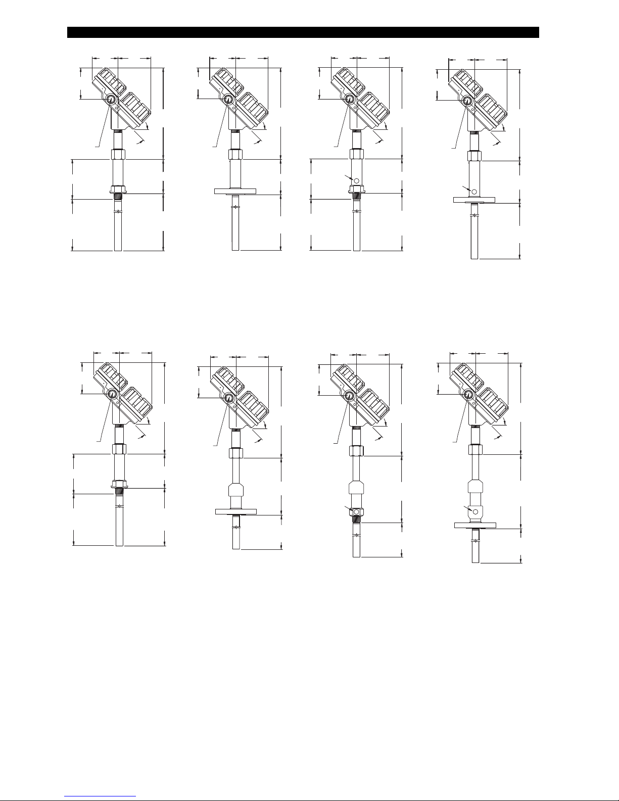
42
DIMENSIONS in mm (inches) - Coaxial GWR probes
1
37 (5.39)
1
44
(5.68)
8
3
(3.28)
1
05
(4.12)
256
(
10.08)
256
(
10.08)
102
(4.00)
102
(4.00)
2
cable
entries
45°
7MR / 7MT
with threaded connection
Probe Insertion
L
ength
BSP
Probe Insertion
L
ength
NPT
162 (6.38)
171
(6.73)
83
(3.28)
105
(4.12)
256
(10.08)
102
(4.00)
2 cable
entries
45°
7MM / 7MN
with threaded connection
Probe Insertion
Length
B
SP
P
robe Insertion
Length
NPT
168 (6.61)
7MR / 7MT
with flanged connection
83
(3.28)
105
(4.12)
2 cable
e
ntries
4
5°
Probe
Insertion
Length
256
(
10.08)
102
(4.00)
2
06 (8.11)
1
/4" NPT
plugged
1
/4"
NPT
plugged
7MM / 7MN
with flanged connection
83
(3.28)
105
(4.12)
2
cable
entries
45°
P
robe
Insertion
Length
7MD/7MS/7MQ
with threaded connection
7MD/7MS/7MQ
with flanged connection
83
(3.28)
105
(
4.12)
256
(10.08)
102
(4.00)
2 cable
entries
45°
Probe
Insertion
Length
83
(3.28)
105
(4.12)
256
(10.08)
102
(4.00)
2 cable
e
ntries
45°
Probe Insertion
Length
BSP
Probe Insertion
Length
NPT
7ML
with flanged connection
375 (14.76)
83
(3.28)
105
(
4.12)
256
(
10.08)
102
(
4.00)
2 cable
e
ntries
45°
Probe
Insertion
Length
1
/4" NPT
plugged
7ML
with threaded connection
297 (11.69)
83
(3.28)
105
(4.12)
256
(10.08)
1
02
(4.00)
2
cable
entries
45°
Probe
Insertion
Length
1
/4" NPT
plugged
7MD: 199 (7.83)
7MS/7MQ: 156 (6.14)
7MD: 218 (8.58)
7MS/7MQ: 177 (6.97)
7
MD: 277 (10.90)
7MS/7MQ: 240 (9.45)
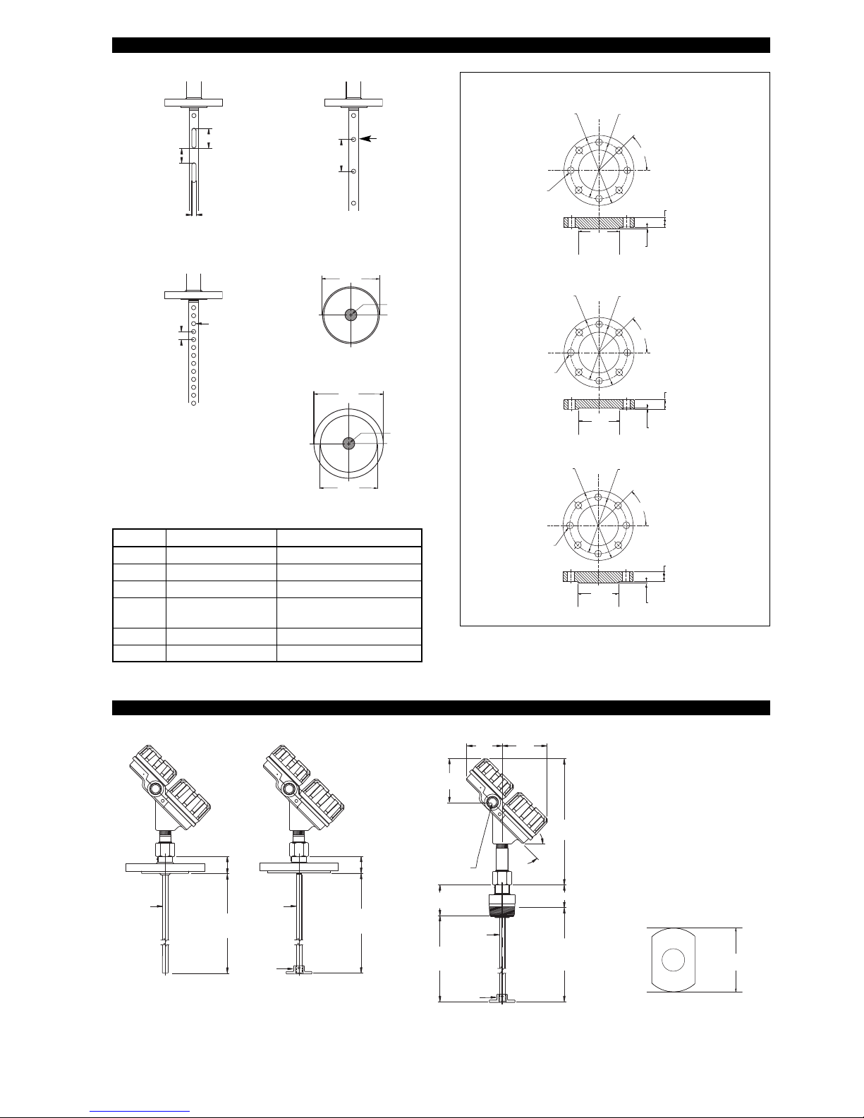
43
DIMENSIONS in mm (inches) - Coaxial GWR probes
Coaxial GWR Probe,
End View
V
enting holes
for level
A
B
C
D
E
Venting holes
for interface
Slots for 7MR-A, 7MD-A/V/W
(order per “x” description)
50
(
1.97)
20
(0.79)
4 (0.16)
Dim.
Small coax mm (inch)
Large coax mm (inch)
A 305 (12) 305 (12)
B Ø 6,4 (0.25) Ø 12,7 (0.5)
C 19 (0.75) 25,4 (1)
D 22,5 (0.88)
45 (1.75) - SST
49 (1.29) - HC and Monel
E 8 (0.31) 16 (0.63)
F 32 (1.25)
Proprietary flanges
Ø 229
(9.0)
3
2
(1.125)
Fisher 249B/259B (600 lbs), carbon steel
133
(5.23)
6
(.22)
Ø 184
(
7.25)
Ø 22
(.875)
45°
Ø 143
(5.625)
29
(1.125)
Fisher 249C (600 lbs), 316 stainless steel
86
(3.375)
5
(.188)
Ø 121
(4.750)
Ø 11
(.438)
45°
Ø
191
(7.50)
29
(1.125)
Masoneilan (600 lbs), 316 carbon steel
1
02
(4.00)
6
(.25)
Ø 149
(5.875)
Ø 22
(.875)
4
5°
DIMENSIONS in mm (inches) - Single Rod
7MF-F
with PFA
faced-flanged
connection
Ø Rod
Bare 13 (0.50) /
PFA insulated
16 (0.62)
60
(2.36)
Probe
Insertion
Length
7MF/7MJ
with threaded connection
7MF/7MJ
with flanged
connection
7MF: 60 (2.36)
7MJ: 150 (5.91)
Optional
Spacer
13 (0.50)
Ø Rod
Probe
Insertion
Length
B
83
(3.28)
105
(4.12)
256
(10.08)
7MF: 36 (1.42)
7MJ: 126 (4.96)
7MF: 57 (2.24)
7MJ: 147 (5.79)
Optional Spacer
102
(4.00)
Ø Rod
Bare 13 (0.50) /
PFA insulated
16 (0.62)
2 cable
entries
Probe Insertion
Length
BSP
Probe Insertion
Length
NPT
45°
Spacer (end view)
49
(1.90)
7MQ End View
F
E
D

44
DIMENSIONS in mm (inches) - Hygienic
109
(4.28)
43° View
5
2
(2.05)
58
(2.28)
108
(
4.25)
9
5
(3.75)
102
(4.00)
89
(3.50)
70
(
2.75)
2 holes
Ø
9,5
(0.37)
Cable entry
Cable entry
19
(
0.75)
840 or 3660
(
33 or 144)
60
(
2.36)
6
0
(2.36)
175
(6.89)
43°
43°
Remote Electronics
Integral Electronics
52
(2.05)
58
(2.28)
all except 3/4" Tri-Clamp®connection
7MF: 60 (2.36)
7MH: 70 (2.76)
13 (0.50)
Ø Rod
Process
Connection
Probe
Insertion
Length
3/4" Tri-Clamp®connection
60
(2.36)
6 (0.25)
Ø Rod
Process
Connection
Probe
Insertion
Length
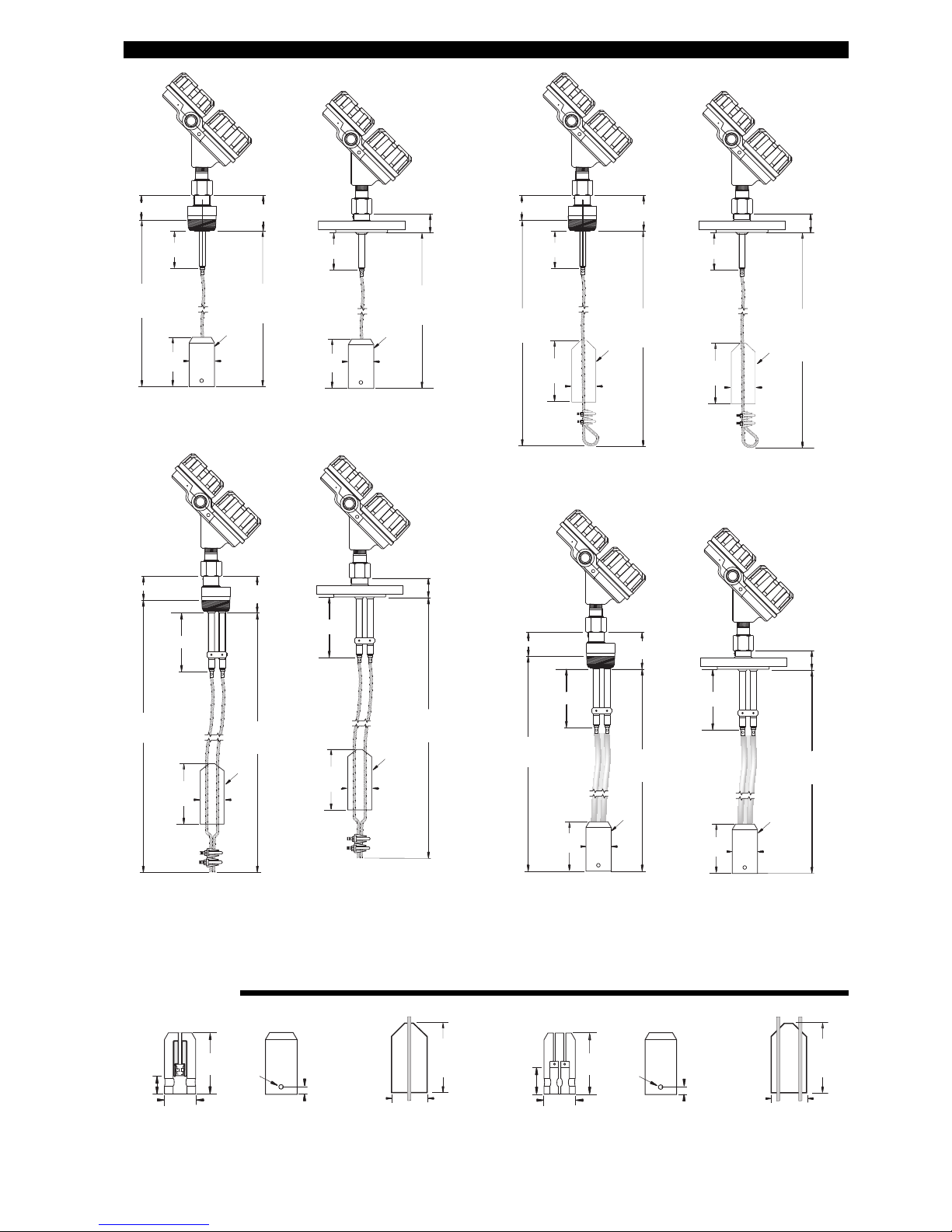
45
DIMENSIONS in mm (inches) - cable GWR probe
7M1
with threaded connection
4
1 (1.61)
59 (2.32)
Probe Insertion
Length
N
PT
Probe Insertion
Length
B
SP
6
10 (24)
7M5
with threaded connection
93 (3.66)
111 (4.37)
Probe Insertion
Length
NPT
Probe Insertion
Length
BSP
7
6 (3)
7M7
with threaded connection
6
2 (2.44)
8
0 (3.13)
Probe Insertion
L
ength
NPT
Probe Insertion
Length
BSP
7
6 (3)
Ø 51
(2)
99
(
3.88)
Ø
51
(2)
Ø 51
(2)
Ø 51
(2)
Ø 51
(2)
Ø 51
(2)
Ø 51
(2)
Ø 51
(2)
7M7
with flanged connection
83 (3.25)
Probe Insertion
L
ength
76 (3)
7M5
with flanged connection
114 (4.49)
Probe Insertion
Length
76 (3)
7M1
with flanged connection
62 (2.44)
Probe Insertion
Length
6
10 (24)
7M2
with threaded connection
6
2 (2.44)
80 (3.13)
Probe Insertion
L
ength
NPT
Probe Insertion
L
ength
BSP
7
6 (3)
7M2
with flanged connection
83 (3.25)
Probe Insertion
L
ength
7
6 (3)
9
9
(3.88)
152
(6)
152
(6)
Weight
Weight
Weight
Weight
152
(6)
Weight
152
(6)
Weight
73
(2.88)
Weight
73
(2.88)
Weight
Additional weight
TFE Weight
450 g (1 lb.)
7M1
SST Weight
2,25 kg (5 lbs)
7M2
29 (1.13)
Ø 51
(2)
Ø 51
(2)
Ø 13,2
(0.52)
99
(3.88)
19 (0.75)
152
(6)
TFE Weight
284 g (10 oz.)
7M7
SST Weight
2,25 kg (5 lbs)
7M5
32 (1.25)
Ø 51
(2)
Ø 51
(2)
Ø 13,2
(0.52)
73
(2.88)
19 (0.75)
152
(6)
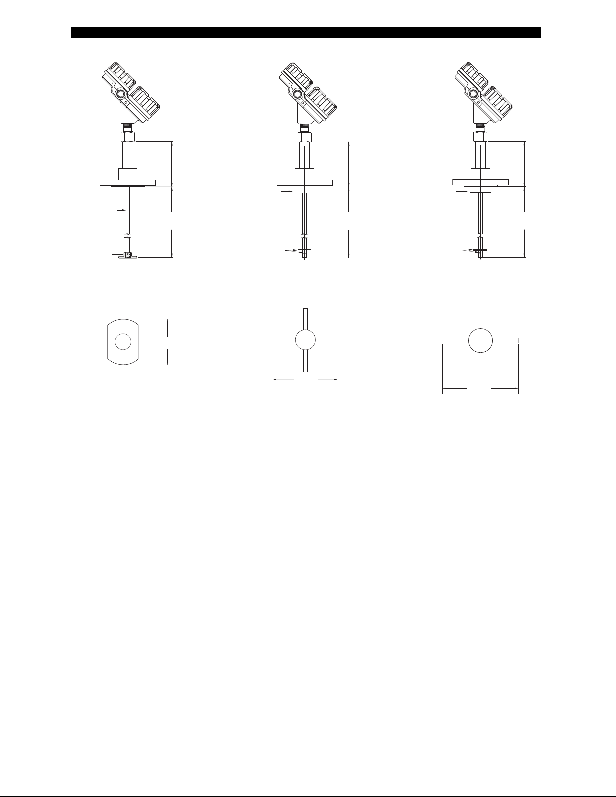
46
DIMENSIONS in mm (inches) - cage GWR probe
Probe
Insertion
Length
T
eflon
®
s
pacer
Ø
13 (0.50) rod
Probe
Insertion
Length
PEEK spacer
Ø 19 (0.75) rod
Probe
I
nsertion
Length
PEEK spacer
Ø 25 (1) rod
7MG - 2" cage
7MG - 3" cage
7MG - 4" cage
Spacer (end view)
4
9
(1.90)
187
(7.37)
187
(7.37)
Ø
71 (2.80)
Ø 95 (3.77)
187
(
7.37)
Spacer (end view)
71 (2.80)
Spacer (end view)
94 (3.70)
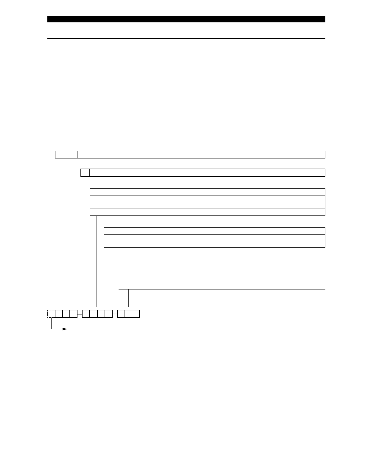
47
MODEL IDENTIFICATION
1. Code for ECLIPSE 705 transmitter head/electronics
750 5
POWER
complete code for ECLIPSE 705 transmitter head/electronics
5 24 V DC, two wire loop powered
BASIC MODEL NUMBER
705 Eclipse 705 guided wave radar transmitter
OUTPUT AND ELECTRONICS
ACCESSORIES
A Digital display and keypad
0 - Blind transmitter (no display/keypad) for dual compartment housing
- Blind housing cover for hygienic housing
SEE NEXT PAGE
10 4-20 mA with HART®– standard electronics (SFF of 84.5%)
1A 4-20 mA with HART®– SIL enhanced electronics (SFF of 91%)
20 Foundation Fieldbus™ communication
30 Profibus PA™ communication
X = product with a specific customer requirement
A complete measuring system consists of:
1
.Eclipse transmitter head/electronics
2.Eclipse 705 GWR probe
3.Free of charge: Eclipse 705 DTM (PACTware™) can be downloaded from www.magnetrol.com.
4.Option: MACTek Viator USB HART
®
interface: order code: 070-3004-002
5
.Option: - TFE spacer for single rod metal GWR probes; order code: 089-9114-001 (7MF-A), 089-9114-002 (7MF-B),
- 089-9114-003 (7MF-C)
- PEEK spacer for single rod 7MJ GWR probe; order code: 089-9114-005 (7MJ-A), 089-9114-006 (7MJ-B),
- 089-9114-007 (7MJ-C)
- Additional weight for 7M1 GWR probe; order code: 089-9120-001
- Additional weight for 7M7 GWR probe; order code: 089-9121-001
- Additional weight for 7M2 GWR probe; order code: 004-8778-001
- Additional weight for 7M5 GWR probe; order code: 004-8778-002

48
MODEL IDENTIFICATION
1. Code for ECLIPSE 705 transmitter head/electronics
750 5
complete code for ECLIPSE 705 transmitter head/electronics
CABLE ENTRY
1 M20 x 1,5 (2 entries - 1 plugged)
0 3/4" NPT (2 entries - 1 plugged)
4 1/2" NPT (1 entry)
MOUNTING / HOUSING MATERIAL / APPROVAL
¿
1
1 Weatherproof
A1 ATEX intrinsically safe (digit 5 = 1) / ATEX FISCO (digit 5 = 2 or 3)
C1 ATEX flameproof enclosure
E1 ATEX non sparking (digit 5 =1) / ATEX FNICO (digit 5 = 2 or 3)
I
ntegral mount electronics
Cast aluminium - dual compartment
12 Weatherproof
A2 ATEX intrinsically safe (digit 5 = 1) / ATEX FISCO (digit 5 = 2 or 3)
C
2 ATEX flameproof enclosure
E2 ATEX non sparking (digit 5 =1) / ATEX FNICO (digit 5 = 2 or 3)
Cast SST - dual compartment
13 Weatherproof
A3 ATEX intrinsically safe (digit 5 =1) / ATEX FISCO (digit 5 = 2 or 3)
304 SST - IP 67 - hygienic
23 Weatherproof
B3 ATEX intrinsically safe (digit 5 =1) / ATEX FISCO (digit 5 = 2 or 3)
304 SST - IP 67 - hygienic
29 Weatherproof
B9 ATEX intrinsically safe (digit 5 =1) / ATEX FISCO (digit 5 = 2 or 3)
304 SST - IP 67 - hygienic
21 Weatherproof
B1 ATEX intrinsically safe (digit 5 = 1) / ATEX FISCO (digit 5 = 2 or 3)
D1 ATEX flameproof enclosure
F1 ATEX non sparking (digit 5 =1) / ATEX FNICO (digit 5 = 2 or 3)
84 cm (33") remote mount electronics
Cast aluminium - dual compartment
22 Weatherproof
B2 ATEX intrinsically safe (digit 5 = 1) / ATEX FISCO (digit 5 = 2 or 3)
D2 ATEX flameproof enclosure
F2 ATEX non sparking (digit 5 =1) / ATEX FNICO (digit 5 = 2 or 3)
Cast SST - dual compartment
27 Weatherproof
B7 ATEX intrinsically safe (digit 5 = 1) / ATEX FISCO (digit 5 = 2 or 3)
D7 ATEX flameproof enclosure
F7 ATEX non sparking (digit 5 =1) / ATEX FNICO (digit 5 = 2 or 3)
3,66 m (144") remote mount electronics (consult factory for applications with
ε
r
< 10)
Cast aluminium - dual compartment
28 Weatherproof
B8 ATEX intrinsically safe (digit 5 = 1) / ATEX FISCO (digit 5 = 2 or 3)
D8 ATEX flameproof enclosure
F8 ATEX non sparking (digit 5 =1) / ATEX FNICO (digit 5 = 2 or 3)
Cast SST - dual compartment
X = product with a specific customer requirement
¿
For IEC approval, use ATEX approval and clearly request IEC nameplate.
SEE PREVIOUS PAGE

49
MODEL IDENTIFICATION
7 M
MATERIAL OF CONSTRUCTION - wetted parts (including process connection flange when applicable)
complete code for ECLIPSE 705 GWR probe
A 316/316L (1.4401/1.4404) stainless steel
B Hastelloy C (2.4819)
C Monel (2.4360)
E 316/316L (1.4401/1.4404) stainless steel 0,4 µm Ra (15 Ra) electropolished surface finish
F PFA insulated 316/316L (1.4401/1.4404) stainless steel
G AL-6XN stainless steel (UNS N08367) 0,4 µm Ra (15 Ra) electropolished surface finish
H Hastelloy®C22 (2.4602) 0,4 µm Ra (15 Ra) electropolished surface finish
L 316L (1.4435) stainless steel 0,4 µm Ra (15 Ra) electropolished surface finish
4 PFA insulated 316/316L (1.4401/1.4404) stainless steel
V 316/316L (1.4401/1.4404) stainless steel with High Temp PEEK®spacers εr: ≥ 1,7
W 316/316L (1.4401/1.4404) stainless steel with Teflon®spacers εr: ≥ 1,4
N Enlarged coax 316/316L (1.4401/1.4404) stainless steel
P Enlarged coax Hastelloy C (2.4819)
R Enlarged coax Monel (2.4360)
BASIC MODEL NUMBER
7MB Twin Rod GWR probe for liquid level – WHG approved εr: ≥ 1,9
7
MD HTHP GWR probe for level/interface – WHG approved εr: ≥ 2,0 if digit 4 = A, B or C
7MF Single rod GWR probe εr: ≥ 1,9/10
7MG Cage GWR probe for level/interface
7MH Hygienic single rod GWR probe
7M J HTHP single rod GWR probe εr: ≥ 1,9/10
7ML
HTHP GWR probe for level
/interface
with flushing connection
εr: ≥ 2,0 if digit 4 = A, B or C
7MM GWR probe for level with flushing connection εr: ≥ 1,4
7MN GWR probe for interface
with flushing connection
upper liq: εr: ≥ 1,4 and ≤ 5 / lower liq: ≥ 15
7MQ
Coaxial GWR probe for saturated steam applications, incl. steam compensation / reference target; 345 °C (650 °F) max.
7
MR GWR probe for level – WHG approved εr: ≥ 1,4
7MS
Coaxial GWR probe for saturated steam applications, incl. steam compensation / reference target; 300 °C (575 °F) max.
7MT GWR probe for interface upper liq: εr: ≥ 1,4 and ≤ 5 / lower liq: ≥ 15
7
M1 Single cable GWR probe in 316 stainless steel (1.4401) εr: ≥ 1,9/10 – liquids
7M2 Single cable GWR probe in 316 stainless steel (1.4401) εr: ≥ 4,0 – solids
7M5 Twin cable GWR probe in FEP coated 316 SST (1.4401) εr: ≥ 1,9 – solids
7M7 Twin cable GWR probe in FEP coated 316 SST (1.4401) ε
r: ≥ 1,9 – liquids
PROCESS CONNECTION - SIZE/TYPE (consult factory for other process connections)
11 3/4" NPT
22 1" BSP (G 1")
Threaded
41 2" NPT
42 2" BSP (G 2")
23 1" 150 lbs ANSI RF
24 1" 300 lbs ANSI RF
25 1" 600 lbs ANSI RF
2K 1" 600 lbs ANSI RJ
2L 1" 900 lbs ANSI RJ
33 1 1/2" 150 lbs ANSI RF
34 1 1/2" 300 lbs ANSI RF
35 1 1/2" 600 lbs ANSI RF
3K 1 1/2" 600 lbs ANSI RJ
3M 1 1/2" 900/1500 lbs ANSI RJ
3N 1 1/2" 2500 lbs ANSI RJ
43 2" 150 lbs ANSI RF
44 2" 300 lbs ANSI RF
45 2" 600 lbs ANSI RF
4K 2" 600 lbs ANSI RJ
4M 2" 900/1500 lbs ANSI RJ
4N 2" 2500 lbs ANSI RJ
53 3" 150 lbs ANSI RF
54 3" 300 lbs ANSI RF
55 3" 600 lbs ANSI RF
5K 3" 600 lbs ANSI RJ
5L 3" 900 lbs ANSI RJ
5M 3" 1500 lbs ANSI RJ
5N 3" 2500 lbs ANSI RJ
63 4" 150 lbs ANSI RF
64 4" 300 lbs ANSI RF
65 4" 600 lbs ANSI RF
6K 4" 600 lbs ANSI RJ
6L 4" 900 lbs ANSI RJ
6M 4" 1500 lbs ANSI RJ
6N 4" 2500 lbs ANSI RJ
ANSI flanges
X = product with a specific customer requirement
2. Code for ECLIPSE 705 GWR probe
SEE NEXT PAGE

50
MODEL IDENTIFICATION
7 M complete code for ECLIPSE 705 GWR probe
PROCESS SEAL - MATERIAL
0 Viton®GFLT
1 EPDM (Ethylene Propylene)
PEEK®& EPDM ‘O’-rings for 7MH
2 Kalrez®4079
3 HSN (highly saturated nitrile)
4 Buna-N
5 Neoprene
®
6 Chemraz®505
7 Polyurethane
8 Aegis PF 128
A Kalrez®6375
C PEEK®& Viton GF ‘O’-rings for 7MH
N Borosilicate/Inconel
®
X-750 for 7MD/7ML
PTFE for 7MF-E/G/H
Hygienic
TT 300/600 lbs Fisher (249B/259B) in carbon steel
TU 300/600 lbs Fisher (249C) in stainless steel
UT 300/600 lbs Masoneilan flange in carbon steel
UU 300/600 lbs Masoneilan flange in stainless steel
Torque tube mating flanges
PROCESS CONNECTION - SIZE/TYPE
SEE PREVIOUS PAGE
2P3/4" Tri-Clamp
®
3P 1" - 1 1/2" Tri-Clamp
®
4P 2" Tri-Clamp
®
9P 2 1/2" Tri-Clamp
®
5P 3" Tri-Clamp
®
6P 4" Tri-Clamp
®
CS DN 40 DIN 11851
DS DN 50 DIN 11851
VV Varivent Type N (mounting diameter 68 mm)
DN D 50 NEUMO BioControl
VN D 65 NEUMO BioControl
EN D 80 NEUMO BioControl
DR DN 50 DIN 11864-1 Type A
SY DN 11/2" SMS
TY DN 2" SMS
BB DN 25 PN 16/25/40 EN 1092-1 Type A
B
C DN 25 PN 63/100 EN 1092-1 Type B2
BF DN 25 PN 160 EN 1092-1 Type B2
CB DN 40 PN 16/25/40 EN 1092-1 Type A
C
C DN 40 PN 63/100 EN 1092-1 Type B2
CF DN 40 PN 160 EN 1092-1 Type B2
CG DN 40 PN 250 EN 1092-1 Type B2
CH DN 40 PN 320 EN 1092-1 Type B2
C
J DN 40 PN 400 EN 1092-1 Type B2
DA DN 50 PN 16 EN 1092-1 Type A
DB DN 50 PN 25/40 EN 1092-1 Type A
DD DN 50 PN 63 EN 1092-1 Type B2
DE DN 50 PN 100 EN 1092-1 Type B2
DF DN 50 PN 160 EN 1092-1 Type B2
DG DN 50 PN 250 EN 1092-1 Type B2
DH DN 50 PN 320 EN 1092-1 Type B2
D
J DN 50 PN 400 EN 1092-1 Type B2
EA DN 80 PN 16 EN 1092-1 Type A
EB DN 80 PN 25/40 EN 1092-1 Type A
ED DN 80 PN 63 EN 1092-1 Type B2
EE DN 80 PN 100 EN 1092-1 Type B2
EF DN 80 PN 160 EN 1092-1 Type B2
EG DN 80 PN 250 EN 1092-1 Type B2
EH DN 80 PN 320 EN 1092-1 Type B2
EJ DN 80 PN 400 EN 1092-1 Type B2
FA DN 100 PN 16 EN 1092-1 Type A
FB DN 100 PN 25/40 EN 1092-1 Type A
FD DN 100 PN 63 EN 1092-1 Type B2
FE DN 100 PN 100 EN 1092-1 Type B2
FF DN 100 PN 160 EN 1092-1 Type B2
FG DN 100 PN 250 EN 1092-1 Type B2
FH DN 100 PN 320 EN 1092-1 Type B2
FJ DN 100 PN 400 EN 1092-1 Type B2
E
N (DIN) flanges
X = product with a specific customer requirement
2. Code for ECLIPSE 705 GWR probe
SEE NEXT PAGE
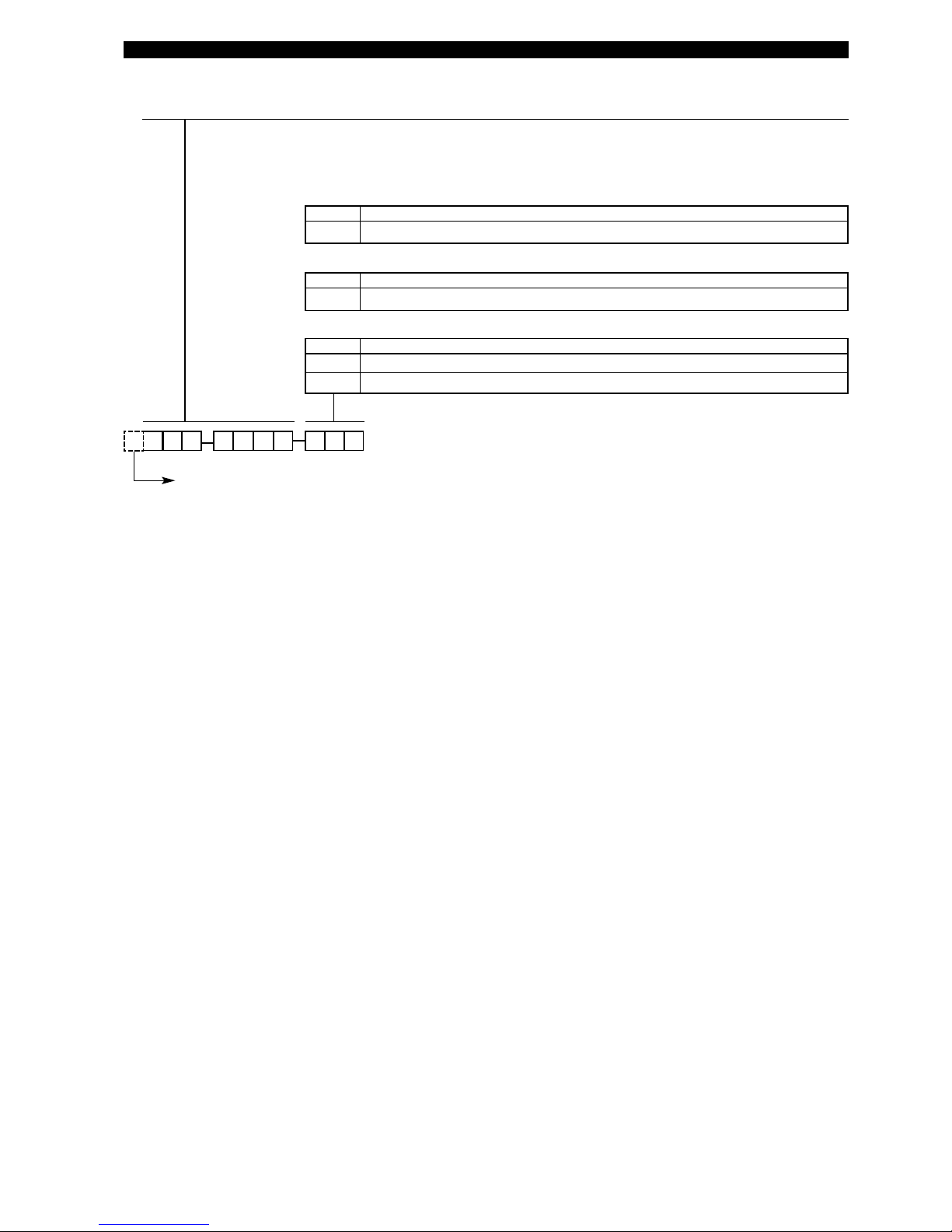
51
MODEL IDENTIFICATION
7 M complete code for ECLIPSE 705 GWR probe
I
NSERTION LENGTH
060 min 60 cm (24")
610 max 610 cm (240") – max 450 cm (177") for 7MQ / 7MS
Rigid GWR probes: specify per cm (0.39") increment
030 min 30 cm (12")
180 max 180 cm (72") for 3/4" Tri-Clamp®process connection
610 max 610 cm (240") for all other process connections
Hygienic GWR probes: specify per cm (0.39") increment
0
02 min 2 m (6.56')
022 max 22 m (72.18')
Flexible GWR probes: specify per m (3.28') increment
SEE PREVIOUS PAGE
X = product with a specific customer requirement
2. Code for ECLIPSE 705 GWR probe

52
MODEL IDENTIFICATION
2. Code for ECLIPSE®705 Top/Bottom GWR probe and cage
Additional dimensions are provided (see drawings at bottom of this page):
- Dimension A: top of process connection up to 20 mA range
- Dimension B: bottom of process connection up to 4 mA range
- Level Range, if different from 356 mm (14")
7AE K 0
MATERIAL OF CONSTRUCTION - wetted parts (including process connection flange when applicable)
complete code for ECLIPSE 705 Top/Bottom GWR probe and cage
Cage and Flanges GWR probe
K 316/316L (1.4401/1.4404) stainless steel
316/316L (1.4401/1.4404) stainless steel
M
Carbon steel
LEVEL RANGE
LIQUID TYPE / OPERATING TEMPERATURE
A
356 mm (14")
PROCESS CONNECTION - SIZE/TYPE
33 1 1/2" 150 lbs ANSI RF
34 1 1/2" 300 lbs ANSI RF
35 1 1/2" 600 lbs ANSI RF
43 2" 150 lbs ANSI RF
44 2" 300 lbs ANSI RF
45 2" 600 lbs ANSI RF
ANSI flanges
B
ASIC MODEL NUMBER
GWR probe suited for in-line external cage mounting
7EK Top/Bottom GWR probe and cage - overfill safe
31 1
1/2" NPT
41
2" NPT
10 Conductive liquids (εr ≥ 10) max +315 °C (+600 °F)
20
All liquids (εr≥ 1,4)
max +260 °C (+500 °F)
39 1
1/2" socket weld
49 2" socket weld
T
hreaded
Welded
OPTIONS
0 None
2 Sight glass connections (sight glass not included)
DIMENSIONS in mm (inches)
Flanged
7EK
Threaded
7EK
Welded
7EK
Optional sight glass
connections
mid
range
mid
range
3/4" NPT-F
mid
range
mid
range
A min 11/2": 102 (4.03)
2": 110 (4.34)
A min 11/2": 64 (2.50)
2": 86 (3.37)
A min 94 (3.69)
A min. 156 (6.12)
B min 76 mm (3")
B min 76 mm (3")
B min 76 mm (3")
B min 76 mm (3")
Max level range
in mm or inches
min 356 (14)
max 6,1 m (240)
Max level range in
mm or inches
min 356 (14)
max 6,1 m (240)
Max level range in
mm or inches
min 356 (14)
max 6,1 m (240)
100 %
0%
100 %
0%
100 %
0%
100 %
0%
X = product with a specific customer requirement

53
Copy blank page and store calibration data for future reference and troubleshooting.
Item Screen Value Value
Vessel Name
Vessel #
Process Medium
Tag #
Electronics Serial # TROUBLESHOOTING
Probe Serial # Working Value Non-Working Value
Level «Level»
Volume (optional) «Volume»
Interface (optional) «IfcLvl»
Interface Volume (opt.) «IfcVol»
Probe Model «PrbModel»
Probe Mount «PrbMount»
Measurement Type «MeasType»
Level Units «LvlUnits»
Probe Length «Probe Ln»
Level Offset «Lvl Ofst»
Volume Units (opt.) «VolUnits»
Strapping Table (opt.) «StrapTbl»
«Pt1..20»
Dielectric «Dielectrc»
Sensitivity «Senstvty»
Loop Control «LoopCtrl»
4mA point «Set 4mA»
20mA point «Set 20mA»
Damping «Damping»
Blocking Distance «BlockDis»
Safety Zone Fault «Sz Fault»
Safety Zone Height «SzHeight»
Safety Zone Alarm
«Sz Alarm Reset»
Fault Choice «Fault»
Threshold «Treshld»
Interface Threshold «IfcThrs»
HART Poll Address «Poll Adr»
Level Trim «Trim Lvl»
Trim 4 mA «Trim 4»
Trim 20 mA «Trim 20»
Level Ticks «LvlTicks»
Interface Ticks (opt.) «IfcTicks»
HF cable «HF Cable»
®
705 Eclipse Guided Wave Radar Transmitter
Configuration Data Sheet
(Make a separate list for each
level and its corresponding
volume

54
Copy blank page and store calibration data for future reference and troubleshooting.
Item Screen Value Value TROUBLESHOOTING
Correct Value Incorrect Value
# of Fiducial Ticks «FidTicks»
Fiducial Spread «Fid Sprd»
Sys Code «Sys Code»
Fiducial Type «Fid Type»
Fiducial Gain «Fid Gain»
Window «Window»
Conversion Factor «Conv Fct»
Scale Offset «Scl Ofst»
Negative Amplitude «Neg Ampl»
Positive Amplitude «Pos Ampl»
Signal «Signal»
Compensate «Compensate»
Derating Factor «DrateFct»
Target Amplitude (7MS)
«TargAmpl»
Target Ticks (7MS) «Targ Tks»
Target Calibration (7MS)
«Targ Cal»
Operating Mode «OperMode»
7EK Correction «7xK Corr»
Electronics temperature «ElecTemp»
Max temperature «Max Temp»
Min temperature «Min Temp»
Safety Zone Hysterisis «SZ Hyst»
®
705 Eclipse Guided Wave Radar Transmitter
Configuration Data Sheet – additional Advanced Diagnostic

55
Notes

IMPORTANT
SERVICE POLICY
Owners of Magnetrol products may request the return of a control; or, any part of a control for complete rebuilding or
replacement. They will be rebuilt or replaced promptly. Magnetrol International will repair or replace the control, at no cost to
the purchaser, (or owner) other than transportation cost if:
a. Returned within the warranty period; and,
b. The factory inspection finds the cause of the malfunction to be defective material or workmanship.
I
f the trouble is the result of conditions beyond our control; or, is NOT covered by the warranty, there will be charges for labour
and the parts required to rebuild or replace the equipment.
In some cases, it may be expedient to ship replacement parts; or, in extreme cases a complete new control, to replace the
original equipment before it is returned. If this is desired, notify the factory of both the model and serial numbers of the
control to be replaced. In such cases, credit for the materials returned, will be determined on the basis of the applicability of
our warranty.
No claims for misapplication, labour, direct or consequential damage will be allowed.
RETURNED MATERIAL PROCEDURE
So that we may efficiently process any materials that are returned, it is essential that a “Return Material Authorisation” (RMA)
form will be obtained from the factory. It is mandatory that this form will be attached to each material returned. This form is
available through Magnetrol’s local representative or by contacting the factory. Please supply the following information:
1. Purchaser Name
2. Description of Material
3. Serial Number and Ref Number
4. Desired Action
5. Reason for Return
6. Process details
Any unit that was used in a process must be properly cleaned in accordance with the proper health and safety standards
applicable by the owner, before it is returned to the factory.
A material Safety Data Sheet (MSDS) must be attached at the outside of the transport crate or box.
All shipments returned to the factory must be by prepaid transportation. Magnetrol will not accept collect shipments.
All replacements will be shipped Ex Works.
ww w . mag n et r ol. c om
BENELUX Heikensstraat 6, 9240 Zele, België -Belgique
FRANCE Tel. +32 (0)52.45.11.11 • Fax. +32 (0)52.45.09.93 • E-Mail: info@magnetrol.be
DEUTSCHLAND Alte Ziegelei 2-4, D-51491 Overath
Tel. +49 (0)2204 / 9536-0 • Fax. +49 (0)2204 / 9536-53 • E-Mail: vertrieb@magnetrol.de
INDIA B-506, Sagar Tech Plaza, Saki Naka Junction, Andheri (E), Mumbai - 400072
Tel. +91 22 2850 7903 • Fax. +91 22 2850 7904 • E-Mail: info@magnetrolindia.com
ITALIA Via Arese 12, I-20159 Milano
Tel. +39 02 607.22.98 • Fax. +39 02 668.66.52 • E-Mail: mit.gen@magnetrol.it
RUSSIA
Business center “Farvater”, Ruzovskaya Street 8B, office 400A, 190013 St. Petersburg
Tel. +7 812 320 70 87 • E-Mail: info@magnetrol.ru
U.A.E. DAFZA Office 5EA 722 • PO Box 293671 • Dubai
Tel. +971-4-6091735 • Fax +971-4-6091736 • E-Mail: info@magnetrol.ae
UNITED Unit 1 Regent Business Centre, Jubilee Road Burgess Hill West Sussex RH 15 9TL
KINGDOM
Tel. +44 (0)1444 871313 • Fax +44 (0)1444 871317 • E-Mail: sales@magnetrol.co.uk
BULLETIN N°: BE 57-600.18
EFFECTIVE: APRIL 2016
SUPERSEDES: September 2015
UNDER RESERVE OF MODIFICATIONS
 Loading...