

856 Instruction Manual
10/18/2010
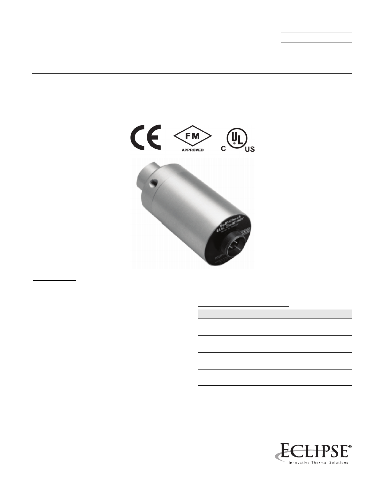
Eclipse Self-Check
UV Scanner
Model 5602-91
Version 1
Introduction
The self-check UV Scanner is used for continuous gas or
oil flames. A mechanical shutter in the scanner closes
briefly every ten seconds, at which time the scanner’s
internal circuit checks for a flame signal. If a signal is
present, indicating a failed sensor, the output signal to the
flame safeguard is stopped and the system shuts down.
The scanner features a high quality fused silica quartz
lens, machined alloy housing with seals and a long life
push-pull electromagnetically driven photo shutter. This
scanner operates with the series 5600 and VF56 series
Veri-Flames, the series 6000 Multi-Flame, Series 6500 BiFlame controllers, and series 7000 Peek-A-Flame.
Factory Mutual (FM) recommends these scanners be
used when any fired equipment is operated continuously
(more than 24 hours without shutdown).
Mechanical Specifications
Parameter Specification
Overall Length 7-3/4" (197mm)
Diameter 3-1/4" (83mm)
Housing Material Aluminum
Finish Clear anodized
Sight Tube Entrance 1" NPT
Purge Air Entrance 1/4" NPT
Purge Air Flow 5 cfm, 10 psi maximum (140
lpm, 0.7mbar)
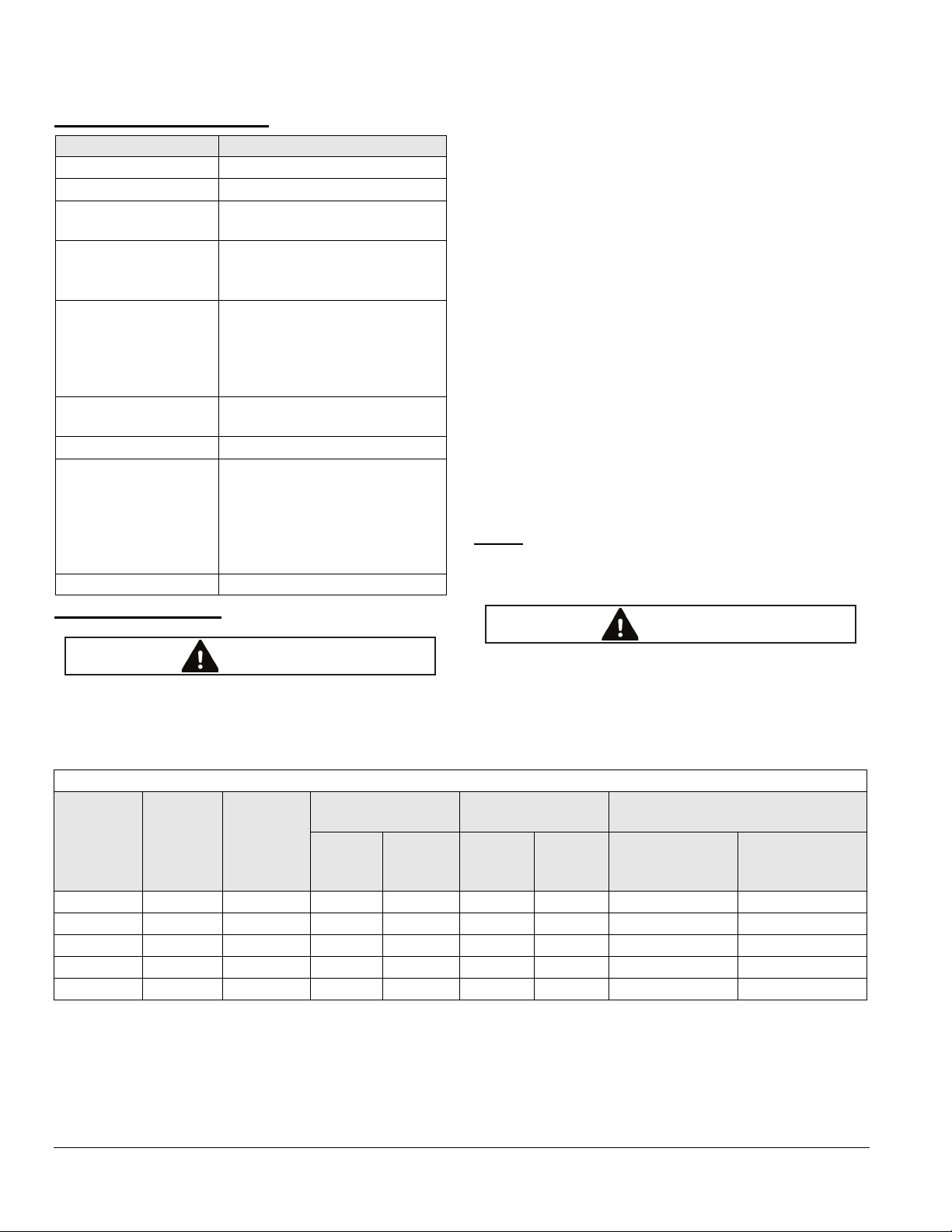
Electrical Specifications
CAUTION
CAUTION
Parameter Specification
Supply Voltage 120V +10/-15%, 50/60 Hz
Supply Current 0.04A
Output Pulse frequency modulated tran-
sistor
Required Accessory Cable with connector, 10 feet
(3m), model 5602-91-7, Part
49602-91-7
Wiring Extension Instrumentation cable with two
pairs of individually shielded #18
AWG conductors, 300V
minimum, BELDEN #9368 or
equivalent.
Temperature Range 0°F to 140°F (-20° to +60°C)
case temperature
Shipping Weight 4.5 lbs (2 kg)
Optical Angle of view @ 2.5° depending
on sight pipe size and length
Spectral Sensitivity: 185 to 260
nanometers; scanner is solar
blind
Option Non-Magnifying lens part 18165
property damage. Be certain that the flame sensor
detects only the pilot and/or main flame of the
intended burner by testing the control system
under varying operating conditions and firing
rates. Follow the test procedures given in this
manual and the equipment provider’s instructions
after installation and at regularly scheduled
maintenance intervals.
Sensor Wiring
Route sensor wiring a sufficient distance from ignition and
other high voltage wiring to avoid electrical interference.
To reduce interference, ground both shields.
If sensor wiring is to extend beyond the supplied 10 ft
(305cm) lengths, use wiring extension as shown in
specifications.
Tables 1 - 4 illustrate how the sensor should be wired to
appropriate controls. Near the end of each of the four
cable leads is a letter tag for identifications. The scanner
is only available for 120V supply. Refer to Figure 1 to use
with a 230 VAC supply.
NOTE:
provide a convenient attachment point. A panel ground
wire must also be run to these points.
The shield wire terminals shown in the tables
Sensor Installation
■ Incorrect sensor installation may cause the sensor
to generate a false flame signal. This can cause
unburned fuel to collect in the combustion
chamber, resulting in explosions, injuries, and
Table 1 - Wiring to Multi-Flame
Multi-Flame
5602-91
Scanner
Connector
Pin
A red Neutral Neutral Neutral Neutral Neutral Neutral Neutral
B white 120 VAC 120 VAC 120 VAC 120 VAC 120 VAC 120 VAC 120 VAC
CblackUV 3 9 3 9 3 9
D green Gnd Return 2 8 2 8 2 8
- shields Ground 4 10 4 10 4 10
5602-91-7
Cable
Wire
Function
J4 Terminal
Scanner#1Scanner#3Scanner#2Scanner
■ Cable lead "B" should only be connected to power
(120 VAC); connecting it to any other terminal will
bypass the safe-start check of the scanner.
Multi-Flame
J5 Terminal
Scanner #5, 6, 9,
10 (also #13, 14,
#4
Expansion Board
J3, J4, J5, J6 Terminals
Scanner #7, 8,
11, 12 (also #15,
17, 18)
16, 19 20)
2
Eclipse Self-Check UV Scanner, V1, Instruction Manual 856, 10/18/2010
 Loading...