

Eclipse 5600 No Purge, 5600 Modulation, 5600 Purge Installation Manual
Installation Guide 818
1/15/2015
Eclipse Veri-Flame Single
Burner Monitoring System
Model 5600
Modulation Model
Purge ModelNo Purge Model
Copyright
Copyright 2008 by Eclipse, inc. All rights reserved
worldwide. This publication is protected by federal
regulation and shall not be copied, distributed,
transmitted, transcribed or translated into any human or
computer language, in any form or by any means, to any
third parties, without the express written consent of
Eclipse, inc.
Disclaimer Notice
In accordance with the manufacturer’s policy of continual
product improvement, the product presented in this
brochure is subject to change without notice or obligation.
The material in this manual is believed adequate for the
intended use of the product. If the product is used for
purposes other than those specified herein, confirmation
of validity and suitability must be obtained. Eclipse
warrants that the product itself does not infringe upon any
United States patents. No further warranty is expressed or
implied.
Liability & Warranty
We have made every effort to make this manual as
accurate and complete as possible. Should you find errors
or omissions, please bring them to our attention so that we
may correct them. In this way we hope to improve our
product documentation for the benefit of our customers.
Please send your corrections and comments to our
Technical Documentation Specialist.
It must be understood that Eclipse’s liability for its product,
whether due to breach of warranty, negligence, strict
liability, or otherwise is limited to the furnishing of
replacement parts and Eclipse will not be liable for any
other injury, loss, damage or expenses, whether direct or
consequential, including but not limited to loss of use,
income, or damage to material arising in connection with
the sale, installation, use of, inability to use, or the repair
or replacement of Eclipse’s products.
Any operation expressly prohibited in this manual, any
adjustment, or assembly procedures not recommended or
authorized in these instructions shall void the warranty.
Document Conventions
There are several special symbols in this document. You
must know their meaning and importance.
The explanation of these symbols follows below. Please
read it thoroughly.
How To Get Help
If you need help, contact your local Eclipse
representative. You can also contact Eclipse at:
1665 Elmwood Rd.
Rockford, Illinois 61103 U.S.A.
Phone: 815-877-3031
Fax: 815-877-3336
http://www.eclipsenet.com
Please have the information on the product label available
when contacting the factory so we may better serve you.
www.eclipsenet.com
Product Name
Item #
S/N
DD MMM YYYY
This is the safety alert symbol. It is used to alert you to potential personal
injurt hazards. Obey all safety messages that follow this symbol to avoid
possible injury or death.
Indicates a hazardous situation which, if not avoided, will result in death
or serious injury.
WARNING
CAUTION
NOTICE
NOTE
2
Indicates a hazardous situation which, if not avoided, could result in
death or serious injury.
Indicates a hazardous situation which, if not avoided, could result in
minor or moderate injury.
Is used to address practices not related to personal injury.
Indicates an important part of text. Read thoroughly.

Table of Contents
Introduction...................................................................................................5
Product Description ..................................................................................5
Audience ..................................................................................................5
Veri-Flame Documents.............................................................................4
Safety .............................................................................................................5
Safety Warnings .......................................................................................5
Capabilities...............................................................................................5
Operator Training .....................................................................................5
Replacement Parts...................................................................................5
DIP Switch Selection ....................................................................................6
Introduction...............................................................................................6
Handling & Storage ..................................................................................6
Approvals of Components ........................................................................6
DIP Switch Location .................................................................................7
DIP Switch Access ...................................................................................7
No Purge DIP Switch Settings..................................................................7
Modulation and Purge DIP Switch Settings..............................................7
Function Summary .......................................................................................9
Introduction...............................................................................................9
Standard Features....................................................................................9
Optional Features.....................................................................................11
System Installation .......................................................................................12
Introduction...............................................................................................12
Interlocks and Limit Switch Input..............................................................12
Combustion Air Switch Input ....................................................................12
Ignition Wiring...........................................................................................12
Low Fire Input...........................................................................................12
Main Valve Closed Switch........................................................................12
High Purge Input ......................................................................................13
Remote Reset ..........................................................................................13
Remote Display and Power Supply..........................................................13
Sensor Installation........................................................................................18
Introduction...............................................................................................18
Sensor Wiring...........................................................................................18
Flame Rods ..............................................................................................18
Scanners ..................................................................................................19
Scanner Sighting Considerations .............................................................19
Eclipse Veri-Flame Single Burner Monitoring System, Model 5600, V1, Installation Guide 818, 1/15/2015 3

Test Procedures............................................................................................20
Introduction...............................................................................................20
Flame Signal Strength..............................................................................20
Minimum Pilot Test...................................................................................20
Pilot Flame Failure Test ...........................................................................20
Main Flame Failure Test (For Interrupted Pilot Systems).........................20
Spark Sighting Test ..................................................................................20
Limits and Interlocks Test.........................................................................21
Maintenance and Troubleshooting .............................................................22
Introduction...............................................................................................22
Monthly Checklist .....................................................................................22
Yearly Checklist........................................................................................22
Troubleshooting........................................................................................23
LED Status ...............................................................................................24
Remote Display Messages...........................................................................27
Introduction...............................................................................................27
Veri-Flame Operating Sequence..............................................................27
Remote Display Diagnostic Messages.....................................................31
Appendix .......................................................................................................i
4
Eclipse Veri-Flame Single Burner Monitoring System, Model 5600, V1, Installation Guide 818, 1/15/2015
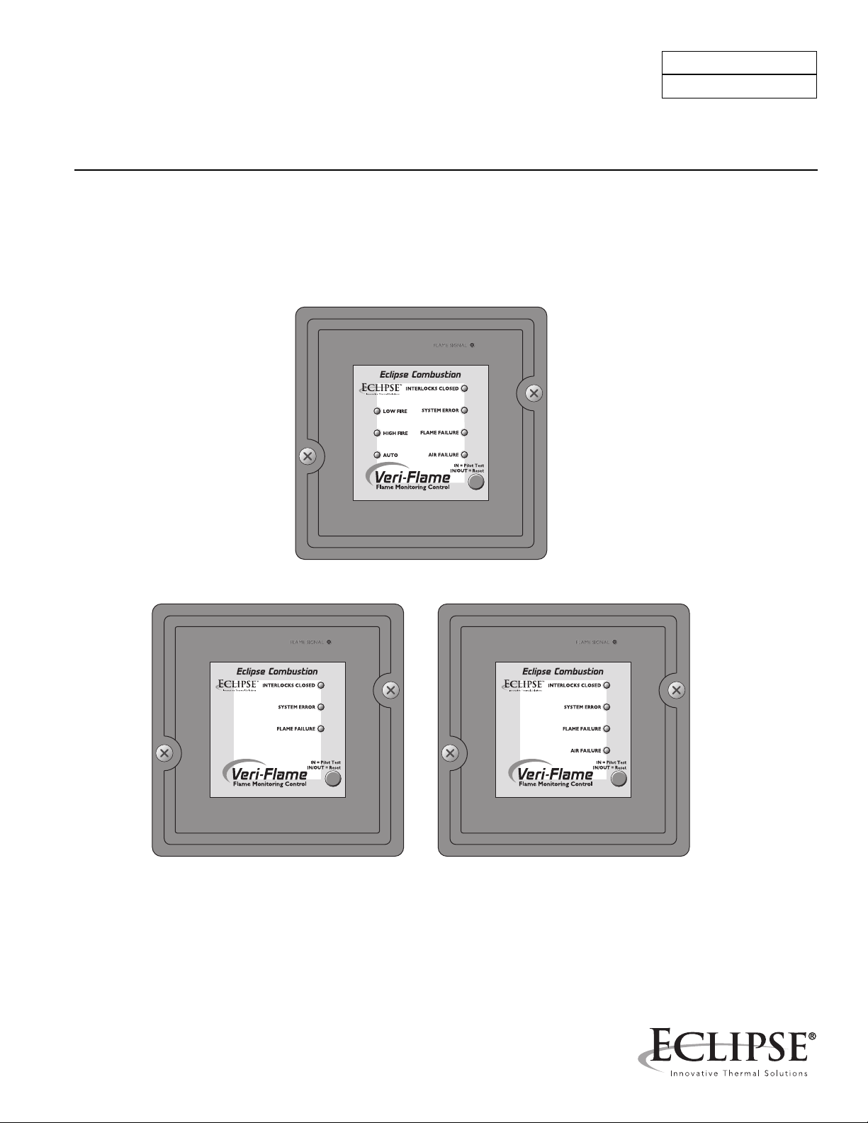
Introduction
Product Description
The Eclipse Veri-Flame Single Burner Monitoring System
controls the start-up sequence and monitors the flame of
single gas, oil, or combination gas/oil burners. There are
three different models of the Veri-Flame line: no purge,
purge and modulation models. Each model features field
selectable trial for ignition (TFI). Each model is also
available for use with three types of flame sensor:
ultraviolet (UV), self-check UV and flame rod
Required components are the Veri-Flame, matching
wiring base and a flame sensor. Optional components
include a remote display and cable, tester, and various
scanner accessories.
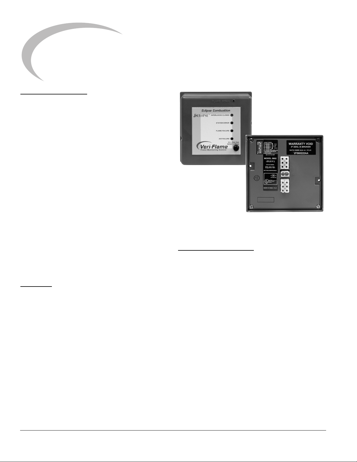
The Veri-Flame No Purge and Purge models are available
in three different series - 5602, 5603 and 5605. The 5602
Series is UL listed for the USA and Canada and FM
approved; the 5605 Series is UL listed and FM approved.
The 5603 Series is for 240 VAC applications and is FM
approved.
1
Figure 1.1 Veri-Flame Single Burner Monitoring
System (Purge Unit Shown)
The Veri-Flame Modulation model is available in two
different series: 5602 and 5603. Both series are capable
of modulation (high purging and low fire start). The 5602
Series is UL recognized for the USA and Canada and FM
approved. The 5603 Series is for 240 VAC and is FM
approved.
Audience
This manual has been written for people who are already
familiar with all aspects of a nozzle-mix burner and its addon components, also referred to as “the burner system”.
These aspects are:
• Design / Selection
• Use
• Maintenance
The audience is expected to have previous experience
with this type of equipment.
Veri-Flame Documents
Installation Guide 818
• This document
Datasheet 818
• Required to complete design and selection
Spare Parts List Series 818
• Recommended replacement part information
Related Documents
• EFE 825 (Combustion Engineering Guide)
• Eclipse Bulletins and Info Guides: 684, 710, 732,
756, 760, 902, 930
Eclipse Veri-Flame Single Burner Monitoring System, Model 5600, V1, Installation Guide 818, 1/15/2015 5
Safety
Important notices which help provide safe burner
operation will be found in this section. To avoid personal
injury and damage to the property or facility, the following
warnings must be observed. All involved personnel should
read this entire manual carefully before attempting to start
or operate this system. If any part of the information in this
manual is not understood, contact Eclipse before
continuing.
Safety Warnings
DANGER
■ The burners, described herein, are designed to mix
fuel with air and burn the resulting mixture. All fuel
burning devices are capable of producing fires and
explosions if improperly applied, installed,
adjusted, controlled or maintained.
■ Do not bypass any safety feature; fire or explosion
could result.
■ Never try to light a burner if it shows signs of
damage or malfunction.
WARNING
■ The burner and duct sections are likely to have
HOT surfaces. Always wear the appropriate
protective equipment when approaching the
burner.
2
NOTICE
■ This manual provides information regarding the
use of these burners for their specific design
purpose. Do not deviate from any instructions or
application limits described herein without written
approval from Eclipse.
Capabilities
Only qualified personnel, with sufficient mechanical
aptitude and experience with combustion equipment,
should adjust, maintain or troubleshoot any mechanical or
electrical part of this system. Contact Eclipse for any
needed commissioning assistance.
Operator Training
The best safety precaution is an alert and trained
operator. Train new operators thoroughly and have them
demonstrate an adequate understanding of the
equipment and its operation. A regular retraining schedule
should be administered to ensure operators maintain a
high degree of proficiency. Contact Eclipse for any needed
site-specific training.
Replacement Parts
Order replacement parts from Eclipse only. All Eclipse
approved valves or switches should carry UL, FM, CSA,
CGA and/or CE approval where applicable.
■ Eclipse products are designed to minimize the use
of materials that contain crystalline silica.
Examples of these chemicals are: respirable
crystalline silica from bricks, cement or other
masonry products and respirable refractory
ceramic fibers from insulating blankets, boards, or
gaskets. Despite these efforts, dust created by
sanding, sawing, grinding, cutting and other
construction activities could release crystalline
silica. Crystalline silica is known to cause cancer,
and health risks from the exposure to these
chemicals vary depending on the frequency and
length of exposure to these chemicals. To reduce
the risk, limit exposure to these chemicals, work in
a well-ventilated area and wear approved personal
protective safety equipment for these chemicals.
6

DIP Switch Selection
3
Introduction
This section describes the location, selection and
description of the Veri-Flame DIP switches, which allow
for sequence and timing functions as well as system
configuration.
Handling & Storage
Handling
• Make sure that the area is clean.
• Protect the components from the weather, damage,
dirt and moisture.
• Protect the components from excessive
temperatures and humidity.
• Take care not to drop or damage components.
Storage
• Make sure that the components are clean and free
of damage.
• Store the components in a cool, clean, dry room.
• After you have made sure that everything is present
and in good condition, keep the components in the
original package as long as possible.
Approval of Components
Gas Piping
All the gas piping must comply with all applicable local
codes and/or standards such as:
• NFPA Standard 54
• ANSI Z223
• EN 746-2
Where to Get the Standards:
The NFPA Standards are available from:
National Fire Protection Agency
Batterymarch Park
Quincy, MA 02269
www.nfpa.org
The ANSI Standards are available from:
American National Standard Institute
1430 Broadway
New York, NY 10018
www.ansi.org
The UL Standards are available from:
333 Pfingsten Road
Northbrook, IL 60062
www.ul.com
Limit Controls & Safety Equipment
All limit controls and safety equipment must comply with
all applicable local codes and/or standards and must be
listed for combustion safety by an independent testing
agency. Typical application examples include:
• American: NFPA 86 with listing marks from UL, FM,
CSA
• European: EN 746-2 with CE mark from TuV,
Gastec, Advantica
Electrical Wiring
All the electrical wiring must comply with all applicable
local codes and/or standards such as:
• NFPA Standard 70
• IEC60364
• CSA C22
• BS7671
The FM Standards are available from:
1151 Boston-Providence Turnpike
PO Box 9102
Norwood, MA 02062
www.fmglobal.com/approvals
Information on the EN standards and where to get
them is available from:
Comité Européen de Normalisation
Stassartstraat 36
B-1050 Brussels
Phone: +32-25196811
Fax: +32-25196819
www.cen.eu
Comité Européen de Normalisation Electronique
Stassartstraat 36
B-1050 Brussels
Phone: +32-25196871
Fax: +32-25196919
www.cenelec.org
Eclipse Veri-Flame Single Burner Monitoring System, Model 5600, V1, Installation Guide 818, 1/15/2015 7
CAUTION
SW2: Pilot selection (On = Intermittent, where pilot
remains on during burner cycle; Off = Interrupted, where
pilot valve closes after main burner is established).
■ To avoid electric shock, shut off the power supply
when installing or removing any control device.
Flame monitoring systems must be installed by a
qualified, licensed technician.
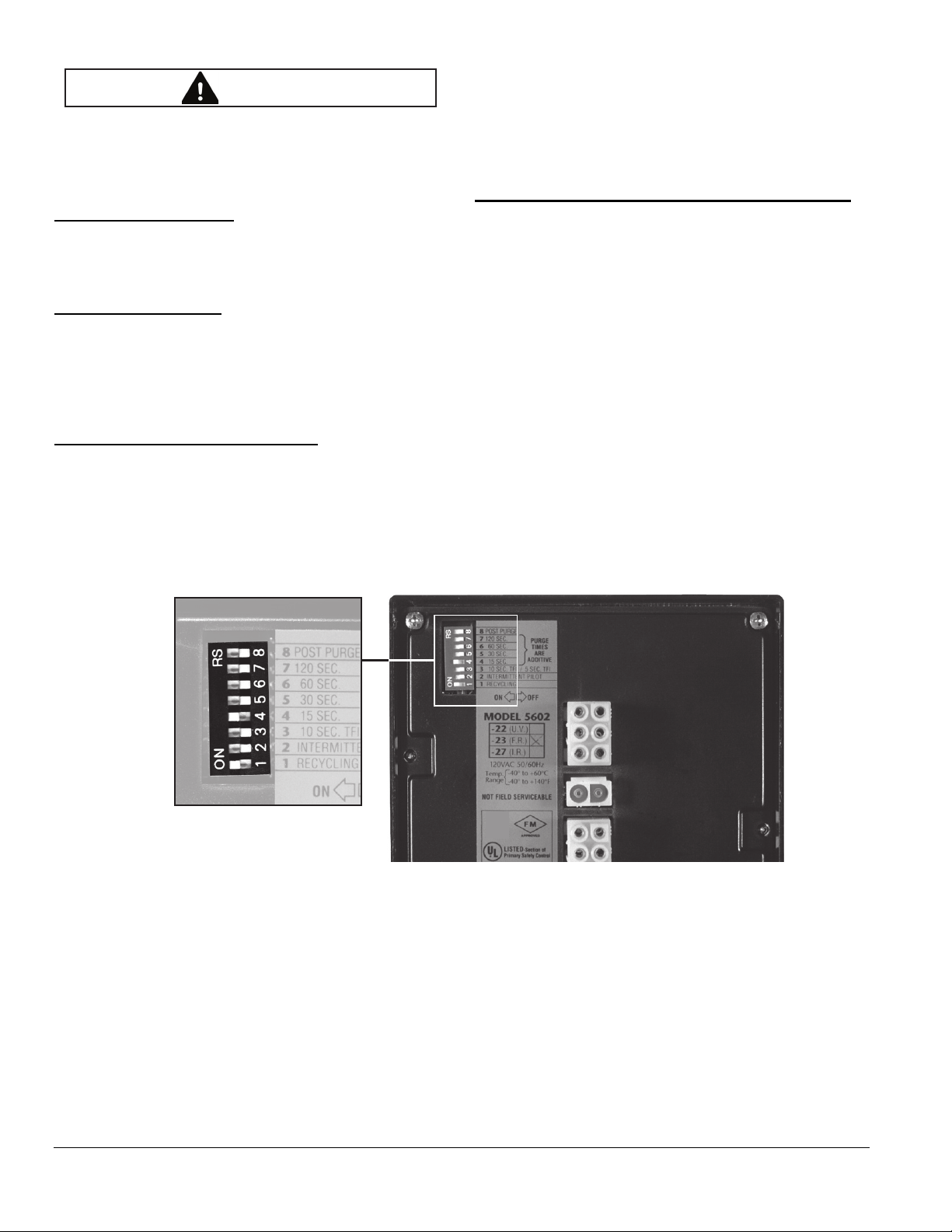
DIP Switch Location
All of the DIP switches are located in the back of each
Veri-Flame unit (see Figure 3.1 on page 11, or the
photograph on page 7).
DIP Switch Access
To gain access to the DIP switches, the Veri-Flame must
be separated from the back box (for visual reference,
please refer to “Dimensions” on page 9). This separation
will expose the DIP switches on the back of the VeriFlame unit.
No Purge DIP Switch Settings
No Purge models of the Veri-Flame only use three of the
eight DIP switches, as shown in the labels in Figure 3.2 on
page 11. They are as follows:
SW1: Recycling mode selection (On = Recycling; Off =
Non-recycling)
SW3: Trial-for-ignition (TFI) range selection (For 5602/
5603 units: On = 10 seconds; Off = 5 seconds. For 5605
units: On = 10 seconds; Off = 15 seconds).
Modulation and Purge DIP Switch Settings
Modulation and purge models of the Veri-Flame use all of
the eight DIP switches, as illustrated in Figure 3.2 on page
11. They are as follows:
SW1: Recycling mode selection (On = Recycling; Off =
Non-recycling)
SW2: Pilot selection (On = Intermittent, where pilot
remains on during burner cycle; Off = Interrupted, where
pilot valve closes after main burner is established).
SW3: Trial-for-ignition (TFI) range selection (For 5602/
5603 units: On = 10 seconds; Off = 5 seconds. For 5605
units: On = 10 seconds; Off = 15 seconds).
SW4 through 7: Purge time selection. Total purge time is
the sum of each switch selected. If all are set off, the trial
for ignition starts when the air switch input comes on.
SW8: Post purge selection. (On = 15 second post purge).
Close-up of DIP switches on
back side of all Veri-Flame models.
Figure 3.1. DIP Switch Location
8
Eclipse Veri-Flame Single Burner Monitoring System, Model 5600, V1, Installation Guide 818, 1/15/2015
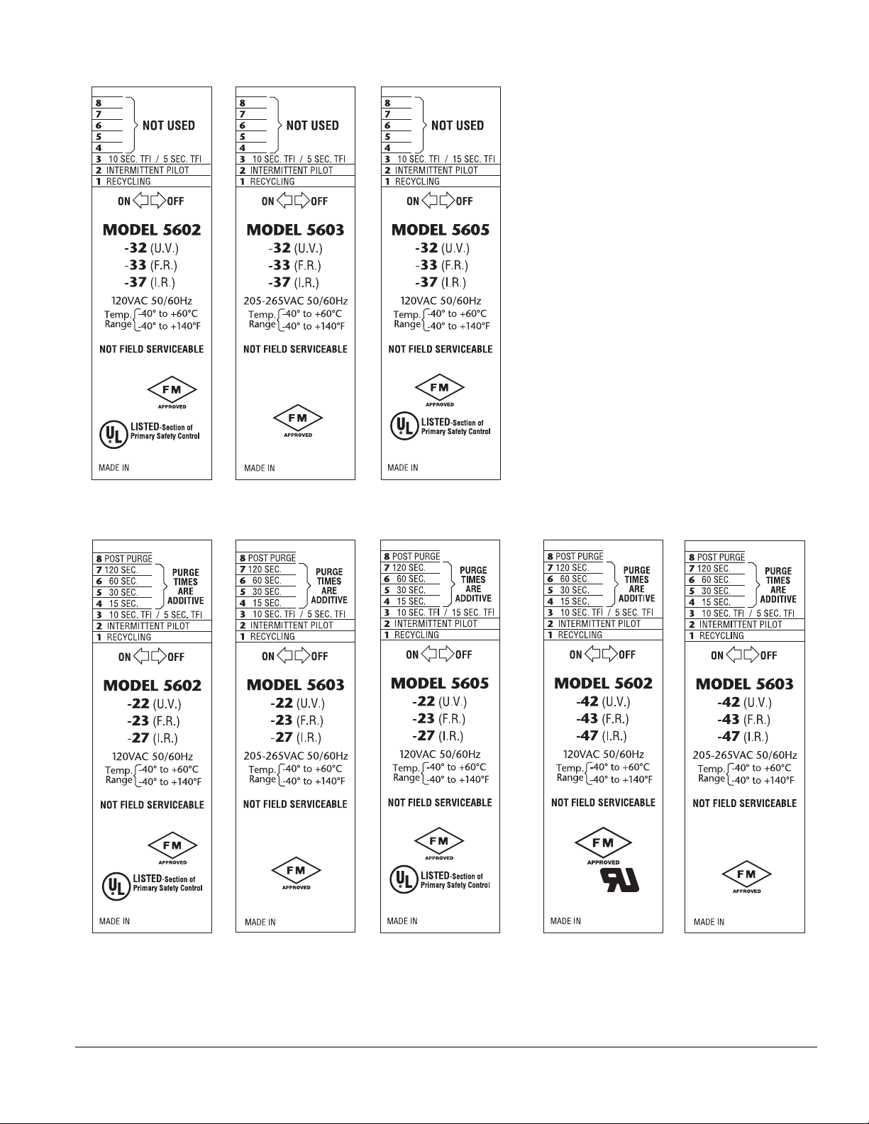
No Purge Models
c us
Purge Models Modulation Models
c us
c us
Figure 3.2. DIP Switch Labels with Selections
Eclipse Veri-Flame Single Burner Monitoring System, Model 5600, V1, Installation Guide 818, 1/15/2015
9
Function Summary
4
Introduction
This section describes the features of the Veri-Flame. It is
divided into three categories: standard features, optional
features and the LED indicator lights on the front cover.
Refer to Figure 5.5 for sequence diagrams.
Standard Features
The following function features are standard on the VeriFlame models as noted:
Interlocks and Limit Switch Input (Terminal 7)
This input is considered the normal operation control or
run input to the Veri-Flame system. Interlocks are
generally pressure or temperature switches which, when
activated, start the burner. Limit switches are generally
pressure, temperature and other switches which, when
activated, stop the burner. The interlocks and limit
switches are wired in series. A break in this circuit will shut
the burner down, but will not produce an alarm.
Combustion Air Switch Input (Terminal 6)
For purge and modulation models: This input is for
monitoring the combustion air switch separately from
other interlocks and limits. The Veri-Flame checks the air
flow switch input is open before start-up, closed during
operation, and open again at burner shutdown, thus
preventing operation with an air switch that is defective,
maladjusted or jumped. This input has about a 2 second
delay to filter out and ignore a momentary interruption.
The input will be proven open before start-up and after
shutdown.
If the input is improperly powered before the fan output is
energized, the system error light will blink. The input must
de-energize within 30 seconds or the Veri-Flame will
lockout.
After the fan output has energized, the air switch input
must be made within 10 seconds. If not proven, then the
system will lockout, the alarm output and the air failure
light will come on. However, if the unit has the optional air
switch input hold feature, the sequence is held indefinitely
without causing a lockout. When the air switch input is
made, then the sequence continues.
Main Fuel Valve Closed Switch (Terminal V)
For purge and no-purge models: The Veri-Flame can be
interlocked with the main valve closed switch. This feature
checks the switch position before start-up and after
shutdown to insure proper valve operation when the
jumper on the base is cut.
Low Fire Start
For modulation models: When wired, the system checks
for the low fire start position prior to light-off.
Main Fuel Valve Closed / High Fire Purge Check
(Terminal D)
For modulation models: This feature is enabled when the
jumper on the base is cut. The system checks that the
high fire position switch and the main valve closed switch
are both made at the end of the high fire purge.
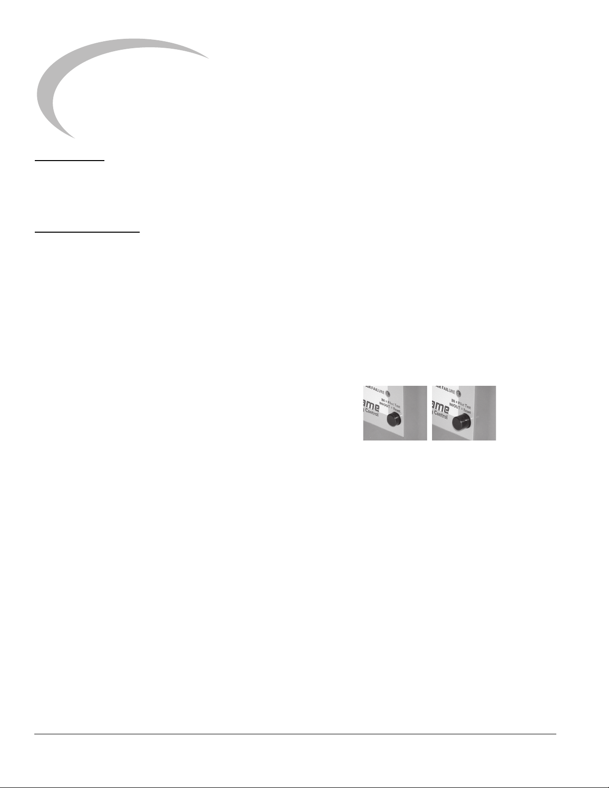
Recycle Mode
Test Mode
(Button In)
For all models: When selected, the Veri-Flame will restart
the sequence after flame or air failure. The recycle mode
allows the system to re-initiate the start-up sequence
automatically provided the main burner has been
operating for at least 35 seconds. If the pilot flame fails to
light during recycling, the system will lock out and
annunciate a pilot flame fail. If the recycle is successful
and the main burner is operational for at least 35 seconds,
the system is ready for another recycle. At no time will the
system recycle in the event of pilot flame fail.
Run Mode
(Button Out)
If the air switch opens during the main firing cycle, the
system will either lockout or recycle, depending on the
DIP switch recycle selection.
10
Eclipse Veri-Flame Single Burner Monitoring System, Model 5600, V1, Installation Guide 818, 1/15/2015

Pilot Test Mode
For all models: This mode is entered by depressing the
TEST/RESET button on the front cover. In the pilot test
mode, the Veri-Flame will hold the sequence once the
pilot flame is established (i.e., the main valve is not
energized). When in the pilot test mode, the green
“Interlocks Closed” light blinks.
To exit the pilot test mode, push the TEST/RESET button
three times (the green “Interlocks Closed” light stops
blinking but remains lit) and the Veri-Flame will restart the
sequence.
Interrupted or Intermittent Pilot
For all models: Pilot mode is selected using the DIP switch
SW2. An interrupted pilot shuts off 10 seconds after the
main valve opens. An intermittent pilot continues during
the entire main flame firing cycle.
Post Purge
For purge and modulation models: Post purge is enabled
by DIP switch SW8. A post purge maintains the
combustion air fan output for 15 seconds after the
interlocks and limit switch input have opened.
Spark, Pilot, Flame and Main Flame Separation
For all models: During the trial for ignition period (TFI), the
pilot valve and ignition coil remains energized. If a flame
signal is present at the end of the TFI, the pilot output
remains on and the ignition coil is de-energized. After a
five second delay to prove the pilot flame, the main gas
valve is energized.
System Errors and Lockout Conditions
A system error (illuminated by the red “System Error” LED
on the front cover) prevents gas ignition. The unit will
continue its sequence after the error is cleared. A lockout
condition energizes the alarm output and de-energizes
the gas valve and ignition outputs. The unit must be reset
to clear the alarm and start the sequence. To reset, the
button must be pressed twice so that the button is in the
out position.
The following system errors result in immediate lockout
conditions:
5. High fire fail (for modulating model)–high fire switch
is not closed at the end of high fire purge.
6. Air failure (for purge and modulation models) – loss
of combustion air anytime during the operational
cycle. The Air Failure LED will be on for this
condition. (See “Recycle Mode” on page 13.)
7. Pilot flame fail (for all models) loss of flame during
the trial for pilot ignition period. The Flame Failure
LED will be on for this condition.
8. Main flame fail (for all models) loss of flame during
the main burner trial for ignition or run period
(recycling not selected). The Flame Failure LED will
be on for this condition.
The following result in lockout conditions after 30
seconds, the system error light blinks about 14 times and
then remains on:
9. If a flame is detected out of sequence, which may
be caused by:
a. A faulty scanner (for all models)
b. Electrical interference on the sensor wiring (for
all models)
c. A flame exists in the burner or in the line of sight
of a scanner, due to a gas leak, product fire or
other conditions (for all models)
10. Air flow switch closed before start-up (for purge
and modulation models).
High to Low Fire Purge Modulation Capability
with High to Low Fire Position Switch Interlocks
For modulation models: The modulation feature
incorporates a high fire purge time and a low fire purge
time into the purge sequence. This feature allows the VeriFlame to sequence internal dry contacts which can be
used by the customer requiring a high fire purge of the
combustion chamber before ignition.
The high fire and low fire purge times are selectable by
means of DIP switches (see Section 3, “DIP Switch
Settings” on page 10):
SW4 15 seconds SW6 60 seconds
SW5 30 seconds SW7 120 seconds
1. Wiring error which puts external voltage on the
output terminals (for all models).
2. Welded internal contacts or other malfunctions in
the Veri-Flame (for all models).
3. Main fuel valve (for all models)–open after cycle
shut down or before start-up. The system error light
blinks twice and then remains on. The fan output
terminal 8 will energize.
4. Low fire fail (for modulating model)–low fire switch
open prior to trial for ignition.
Eclipse Veri-Flame Single Burner Monitoring System, Model 5600, V1, Installation Guide 818, 1/15/2015
The selected times are additive and apply to both the high
fire and low fire purge times (that is, high and low fire times
are always identical).
11
 Loading...