

Page 1
854 Instruction Manual
C
US
10/11/2010
UV Scanner
Model 5600-91
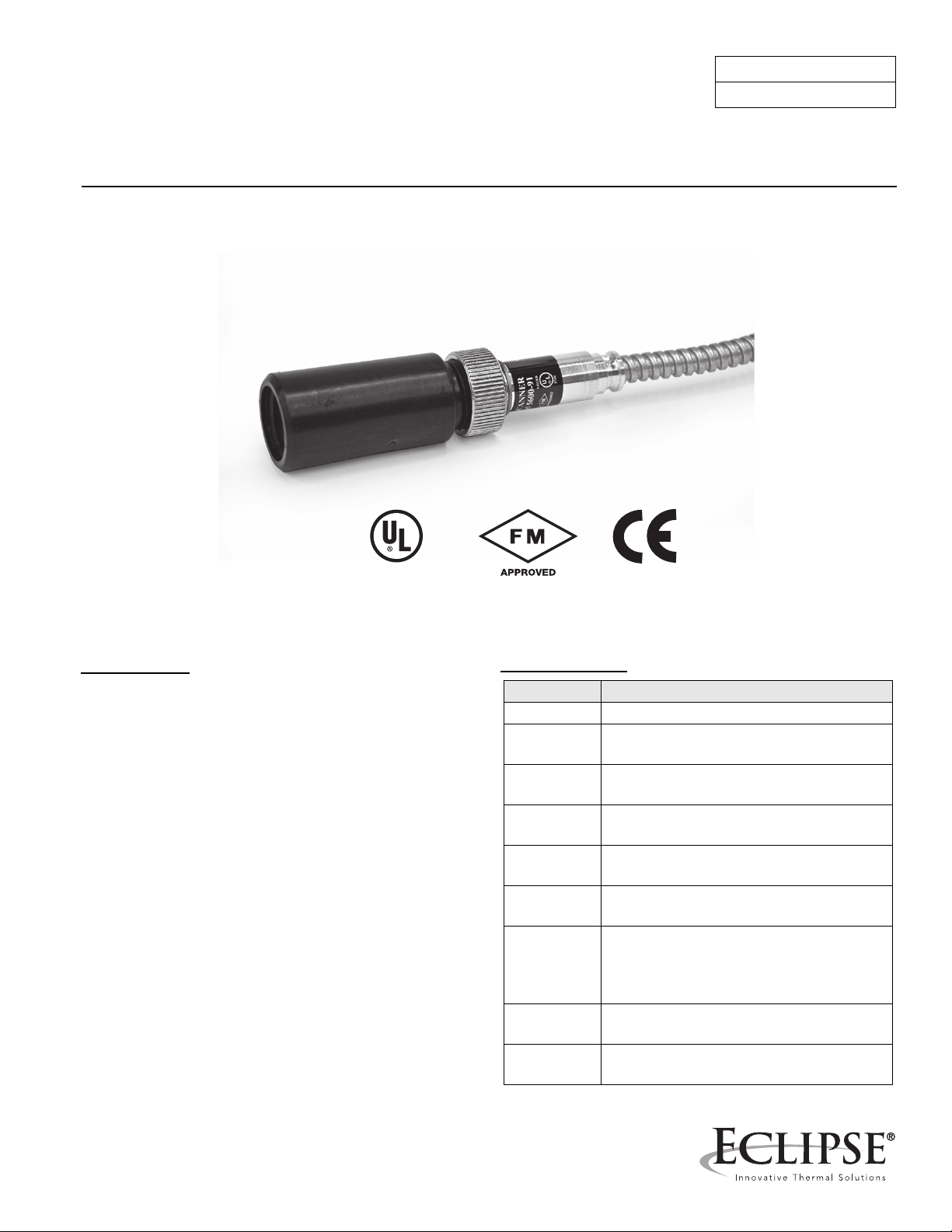
Introduction
This sensor features a high temperature and high
sensitivity ultraviolet (UV) tube for monitoring gas or oil
flames in applications that cycle on and off frequently. The
scanner is UL listed for USA and Canada, and FM
approved when used with Eclipse model 5600 and VF56
series Veri-Flame, model 6000 Multi-Flame, model 6500
Bi-Flame, or series 7000 Peek-A-Flame. This product is
also in conformance with the "CE Mark" Directives when
used with the model VF56 Veri-Flame CE as listed in its
Instruction Manual 818-2. It comes with a 6 ft flexible
metal cable and an insulated coupling.
The UV tube is made of quartz and is filled with a gas that
surrounds two electrodes. These electrodes are
energized continuously by a high voltage. The gas acts as
an insulator in the absence of UV radiation. Combustion
produces UV radiation to ionize the gas and causes
current pulses to flow between the electrodes. These
current pulses result in a flame signal which is transmitted
to the amplifier in the control, where it is processed to
energize and hold in the flame relay.
Specifications
Parameter Specification
Part Number 49600-91
Spectral
Response
Supply
Voltag e
Supply
Current
Wiring 6 foot (183 cm) flexible 3/8" metal conduit
Temperature
Range
Materials Housing: Aluminum
Shipping
Weight
Options Magnifying lens (Part #49600-98)
185 to 260 nm
495 ± 55VDC
0.3 mA
with two #18 AWG conductors
0° to +257°F (-20° to 125°C)
Conduit: Plated Steel
Insulated Coupling: PBT Polyester, Glass
Reinforced
13 oz. (360 grams)
Heat Block Seal 23HBS (Part #400011)
Page 2
Sensor Installation
CAUTION
CAUTION
■ Incorrect sensor installation may cause the sensor
to generate a false flame signal. This can cause
unburned fuel to collect in the combustion
chamber, resulting in explosions, injuries, and
property damage. Be certain that the flame sensor
detects only the pilot and/or main flame of the
intended burner by testing the control system
under varying operating conditions and firing
rates. Follow the test procedures given in this
manual and the equipment provider’s instructions
after installation and at regularly scheduled
maintenance intervals.
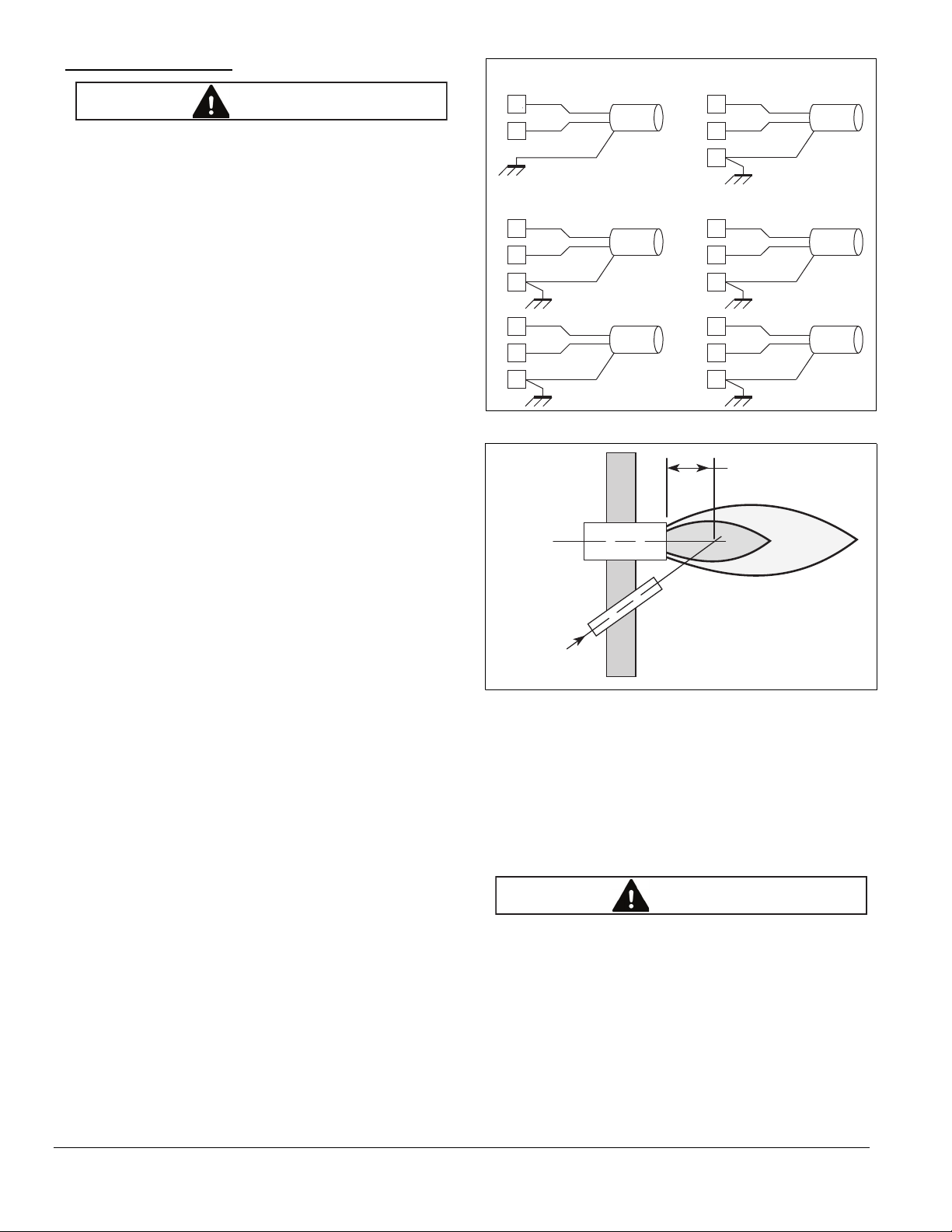
Sensor Wiring
Veri-Flame
Blue
S1
S2
Yellow
Multi-Flame
Blue
3
2
Yellow
4
Blue
9
8
Yellow
10
Scanner
Conduit
Scanner
Conduit
Scanner
Conduit
Peek-A-Flame
Blue
7
8
Yellow
2
Bi-Flame
Blue
J4
3
2
Yellow
4
Blue
J5
1
2
Yellow
4
Scanner
Conduit
Scanner
Conduit
Scanner
Conduit
Route sensor wiring a sufficient distance from ignition and
other high voltage wiring to avoid electrical interference.
Some areas may have high levels of electromagnetic
fields or ground currents that require the use of special
cables, isolation and grounding methods. Figure 1
illustrates the sensor wiring to appropriate Eclipse
controls. The blue wire supplies power and carries the
flame signal, the yellow wire connects to circuit common,
and the flexible metal conduit must be connected to earth
grounding.
If sensor wiring is to extend beyond the supplied 6 foot
(183 cm) length, use #14 to #18 AWG wire suitable for at
least 167°F (75°C) and 600 volt insulation.
If each scanner has its own dedicated conduit, unshielded
wiring may be used for wiring runs less than 20 feet (6 m)
and that have at least one foot of separation from ignition
and other high voltage conductors. For wiring runs greater
than 20 feet (6 m) use two-conductor shielded cable (such
as Belden #8719 or #9342, or for extreme temperatures
#83322E). For multiple burner installations, shielded
cables can be run in a common conduit. Use isolated
shielded pairs to avoid the possibility of interference
(cross-talk) between wiring of multiple scanners. The
success of wiring runs of 150 feet (45 m) or more is
dependent upon site conditions; therefore the equipment
layout should be redesigned to allow the control to be
mounted closer to the burner. For these longer wiring
runs, it may be necessary to use a pair of RG62A/U coax
cables (Eclipse #21741) per scanner, with the shielding
insulated and not grounded.
Figure 1.
One-Third of
Main
Flame Length
Burner
Scanner
Sight Line
Figure 2.
Sensor Installation
In most cases, the location for this scanner will be predetermined by the burner manufacturer. However, proper
application of this scanner requires knowledge of the
burner, the combustion chamber, and the process.
Opposing burners, flame swirl patterns, and substance in
the line-of-sight may require special mounting techniques.
■ The UV tube is fragile. Handle carefully and avoid
dropping or sharp blows.
Consult the burner manufacturer’s instructions for
mounting location. The scanner should view the
intersection of the pilot and main flames. It typically should
be aimed at the first third of the flame closest to the burner
nozzle, see Figure 2. Certain unburned hydrocarbons, oil
mist, recirculated flue gas or other contaminants may
mask and absorb the ultraviolet radiation.
2
Eclipse UV Scanner, V1, Instruction Manual 854, 10/11/2010
Page 3

Position the scanner within 18 inches (457 mm) of the
flame. Longer distances are allowed, but could limit the
field of view and may reduce the turndown or firing range
of the burner.
Mount the scanner to a 1/2" NPT pipe nipple to the burner.
Insure that the scanner body does not exceed 257°F
(125°C) from conducted, radiated, or ambient heat. To
protect from high temperatures, use the insulated
coupling (#49099) with a heat block seal (#400011) and
source of clean purging air (5 CFM typical), or a purge
assembly constructed with a 1/2" WYE fitting.
Keep the scanner lens and line-of-sight free of
contamination. Be aware that scanners looking up are
susceptible to dirt and dust settling. Soot, steam, and
unburned hydrocarbons may reduce or even mask the
radiation from the flame. A purging assembly as described
above may alleviate these problems.
and Enter buttons together then release the Reset and
after a few seconds release the Enter.
3. Start the system normally. The control will hold the
operating sequence at the pilot flame step.
4. Measure the flame signal strength as described above.
5. Slowly reduce the pilot fuel until the signal drops out.
Increase the pilot fuel slightly and restart the system.
Observe the flame signal and adjust the pilot fuel as
required to prevent flame failure. This is the minimum
pilot.
6. Take the control out of the pilot test mode and begin the
start-up sequence again. On the Veri-Flame push the
Test/Reset button again so that it pops out to the Run
position. On the Bi-Flame and Multi-Flame press the
Reset button.
Some burners have an open construction allowing the
scanner to view into a furnace. Avoid sighting background
sources of UV light. If necessary, mask the offending
background source by use of an orifice, the magnifying
lens assembly (#49600-98), or a combination of both to
reduce the field of view.
Two model 5600-91 scanners may be installed on one
burner when necessary to view different areas of the
flame to obtain reliable operation. The wires should be
connected in parallel.
Test Procedures
Perform the following tests for every new installation and
at periodic maintenance intervals. Depending on the
burner equipment (such as pilot versus direct spark),
some of the tests may not be possible.
Measuring Flame Signal Strength
Insert the positive probe of a 0-15 VDC voltmeter (100k
ohm minimum input impedance) into the test point on the
control cover. Connect the negative probe to the GND or
terminal for the yellow wire. Readings greater than 4 VDC
are adequate.
Minimum Pilot Test
Run this test on pilot ignited burners to ensure that the
sensor will not detect a pilot flame too small to reliably light
the main flame.
1. Manually shut off the fuel supply to the burner, but not
to the pilot.
2. Put the control in the pilot test mode. On the Veri-Flame
push the Test/Reset button in the Test position (button
in). On the Bi-Flame and Multi-Flame press the Reset
7. When the sequence reaches the main flame trial for
ignition, smoothly restore the fuel supply to the main
burner. If the main burner does not light within five
seconds, immediately shut off the burner fuel supply,
stop the control and purge the system. Attempt to light
the burner again before proceeding with adjustments in
the next step.
8. For burners with an adjustable scanner sighting
assembly, adjust the sighting assembly further away
from the nozzle of the pilot flame thus requiring a larger
minimum pilot for adequate signal strength. For
burners with fixed sighting, increase the pilot flame.
Repeat steps 1 through 8 until the main burner lights off
smoothly and reliably.
Ignition Interference Test
Test the effect of the ignition system (transformer, spark
plug, wiring and grounding) on the flame signal and
control. Ignition interference can decrease or increase the
flame signal strength or can cause erratic operation of the
control. The scanner placement on some burners allows
direct sighting of the spark, creating a strong but false
flame signal. The Eclipse flame control sequence does
not interrupt the spark upon flame detection until after the
trial for ignition period. Therefore spark detection is not a
problem; however ignition interference should still be
reduced or eliminated where possible.
1. Manually shut off the fuel supply to the burner.
2. Start the system normally. Observe the flame signal
during ignition to see if it responds during the spark.
Readings above 2 VDC indicate spark interference or
spark sighting.
Eclipse UV Scanner, V1, Instruction Manual 854, 10/11/2010
3
Page 4

3. On pilot ignited burners, manually shut off the fuel
WARNING
CAUTION
supply to the main burner. For direct spark burners,
lock the burner firing-rate at the start position.
2. Observe the flame signal as the system operates at
various firing rates under process (at temperature)
conditions.
4. Put the control in the pilot test mode (see step 2 of
Minimum Pilot Test above).
5. Start the system normally. Observe the flame signal
during spark and after the trial for ignition. Spark
interference causes the signal during the spark to differ
more than 2 VDC from the signal after the spark.
6. If spark interference is observed, try to minimize its
affect:
a. Ensure proper grounding for the ignition circuit.
b. Isolate the scanner from ground and/or remove
the shield connection from ground.
c. Check for proper spark gap.
d. Clean, repair, or replace faulty wiring and
connectors.
e. Separate or shield the scanner wiring from the
ignition wiring.
f. Reverse the wires feeding the primary to the
ignition transformer.
g. Move the location of the ignition transformer.
Pilot Flame Failure Test
1. Put the control in the pilot test mode (see step 2 of
Minimum Pilot Test above).
2. Start the system normally.
3. After the pilot has lit, manually turn off the fuel supply.
The controller should lock out of flame failure. If not,
then the controller is detecting a false flame signal.
Find the problem and correct it before resuming normal
operation.
Main Flame Failure Test
1. Put the control in the "Run" position (see step 6 of
Minimum Pilot Test above).
2. Start the system normally.
3. Perform the Main Flame Failure Test under these
conditions and verify that the control shuts down in less
than 4 seconds after visually observing that the flame
extinguished.
Limit & Interlock Tests
Periodically check all interlock and limit switches by
manually tripping them during burner operation to make
sure they cause a system to lock out.
■ Never operate a system that is improperly adjusted
or had faulty interlocks or limit switches. Always
replace faulty equipment before resuming
operation. Operating a system with defective or
bypassed safety equipment can cause explosions,
injuries, and property damage.
Maintenance
■ High voltage, turn off power before disconnecting
or installing sensors or controls.
All burner systems must be maintained to ensure their
safe operation. The operator of this equipment must be
trained in safe operating procedures. The owner and
operator must set a regularly scheduled maintenance
interval based on recommendations from the equipment
manufacturers, environmental conditions, and their own
operational history.
System Checks
Periodically test the sensors as described in "Test
Procedures".
Sensor Lens
3. After the sequence lights the main flame, manually shut
off the fuel supply. If the control does not shut down in
less than 4 seconds after visually observing that the
flame extinguished, it may be detecting a false flame
signal. Find the problem and correct it before resuming
normal operation.
Process Conditions Test
1. Start the system normally.
4
Clean the lens regularly with a soft, damp cloth. The
presence of foreign material will measurably reduce the
flame signal strength.
Rotation
To ensure operability of stored items and to reduce the
possibility of extended down-time, periodically swap spare
sensors and control units with active ones.
Eclipse UV Scanner, V1, Instruction Manual 854, 10/11/2010
Page 5

Dimensions in inches (mm)
84
(2134)
72
(1829)
3.13
(79.4)
Ø 0.63
(16)
1/2" Int.
F.N.P.T.
1/2-14
NPT
Thread
1/2-14
NPSL Thread
0.3 (9.58) MIN
Full Threads
2.5
(63.5)
0.47
(11.9)
Ø 1.13
(28.58)
Eclipse UV Scanner, V1, Instruction Manual 854, 10/11/2010
5
Page 6

854 Instruction Manual, 10/11/2010
 Loading...