

Page 1

USER MANUAL
MANUAL DE INSTRUCCIONES
NOTICE D'UTILISATION
BEDIENUNGSANLEITUNG
WPTOUCH
Page 2

Page 3

INSTRUCTION MANUAL
1. IMPORTANT REMARK 04
1.1. Safety Precautions 04
2. INTRODUCTION 04
3. INSTALLATION AND CONNECTION 05
4. OPERATION 06
4.1. WPTOUCH Operating Modes 06
4.2. WPTOUCH Edition and Configuration Modes 08
4.2.1. EDITION Mode 08
4.2.2. CONFIGURATION Mode 10
4.3. Infrared Control 11
4.4. WPTOUCH special status 12
5. FUNCTION LIST 43
6. DIAGRAMS 43
7. TECHNICAL CHARACTERISTICS 46
All numbers subject to variation due to production tolerances. ECLER SA reserves
the right to make changes or improvements in manufacturing or design which may
affect specifications.
3
Page 4

1. IMPORTANT REMARK
We appreciate your confidence in choosing our remote control
wall panel WPTOUCH. In order to obtain the best performance and
efficiency it's VERY IMPORTANT to carefully read and follow all
considerations specified in this manual before connecting the product.
In order to guarantee the optimum operation of this unit, we
strongly recommend that its maintenance be carried out by our Authorised
Technical Services.
1.1. Safety Precautions
Do not expose the unit to rain or water splashes, and do
not place liquid containers or incandescent objects like
candles on top of the unit.
Should any connection / disconnection task be done,
always disconnect the unit from the mains supply.
There are no user serviceable parts inside the unit.
The front panel should not be cleaned with dissolvent or
abrasive substances because silk-printing could be damaged. To clean
it, use a soft cloth slightly wet with water and neutral liquid soap; dry it
with a clean cloth. Be careful that water never gets into the unit through
the holes of the front panel.
2. INTRODUCTION
The WPTOUCH is a remote control wall panel with transflective
LCD display and 3 touch controls: two push buttons and a rotating control
wheel (“jog wheel”). In addition it features an infrared receiver to operate
control functions from a remote control (see section FUNCTIONS
DIAGRAM).
The WPTOUCH has two connection ports (voltage control
analogue outputs and a MIMO-REMOTE digital control bus) able to operate
in two different modes:
1. Analogue mode
In this mode, voltage control output terminals of the control
panel provide the necessary DC voltage to be compatible with:
• MIMO54: source selection and volume functions are
enabled for one of the MIMO54 output zones
• Equipment with a remote control port for volume
(AMPACK series, AMIC and AMIC24, NZA series, MPA
series, etc.): it allows to control the volume of one or more
unit channels.
4
Page 5

2. Digital mode.
In this mode, the WPTOUCH acts as a MI MO88 slave, being
connected to it by means of the MIMO-REMOTE digital control
bus. The functions of the buttons and control wheel and the
information displayed on the WPTOUCH screen will depend on
the MIMO88 setup. In this mode, control voltage outputs are
disabled.
3. INSTALLATION AND CONNECTION
The WPTOUCH can be recessed in wall, inserted into a
standard electrical box or surface mounted, by means of the provided
bracket.
Connections between the WPTOUCH and other equipment to
be remote controlled are:
1. Connection with MIMO54 (analogue volume control,
MUTE and source selection). See diagram.
2. Connection with equipment featuring a 0-10V DC remote
control port for volume (AMPACK series, AMIC and
AMIC24, NZA series, MPA series, etc.). See diagram.
3. Connection with MIMO88 (digital control, programmable
functions). See diagram.
Note: in some cases, a WP-PSU power supply will be necessary due to the
power consumption requirements of the installation, depending on the type
of device WPTOUCH are connected to and/or the amount of them. In c ase
of doubt, please contact our technical support.
5
Page 6

4. OPERATION
4.1. WPTOUCH Operating Modes
After resetting the device (reset) or at startup, the WPTOUCH
will be in analogue mode (ANALOG). If connected to a MIMO88 via its
digital bus, this connection will be established, synchronized, and the digital
mode will be automatically recalled (DIGITAL LOCKED, the icon of
connection appears in LCD display).
Once in digital mode, and if communication is lost between the
devices, the WPTOUCH remains in offline mode (UNLOCKED) until a new
synchronization with MIMO88. If you want to return to analogue mode from
the offline mode, you have to reset the device in order to come back to the
initial stage.
In digital mode, the device can be disabled to prevent unwanted
tampering (DISABLED).
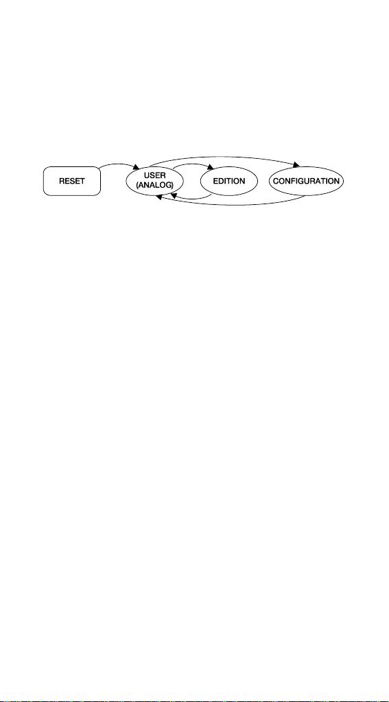
The following diagram illustrates the different WPTOUCH status
and possible transitions between them:
In analogue mode, the functions of the wall panel touch
controls are:
• KEY 1 (left): MUTE ON / OFF. When the MUTE function is
activated (MUTE ON), the volume indicator is replaced on the
second line of the display by the word "MUTE" and an asterisk
appears on the far left of the display. At the same time, the DC
control voltage is modified so that it mutes the device
connected to the WPTOUCH through the analogue remote
control port for DC control voltage.
• KEY 2 (right): source selection, among the maximum number of
selections defined in the CONFIGURATION menu (see below).
The sequence to follow for the source selection is:
1. Press KEY 2: If the panel is set to display the device
name on the first line of the screen, the name of the
active selection will temporarily be displayed instead. The
arrow on the far right of the display indicating the
parameter the wheel is controlling will jump from the
second to the first line of the display.
6
Page 7

2. The rotating wheel allows to scroll available selections.
3. Press KEY 2 again to confirm the new selection (the one
displayed) or KEY 1 to cancel the operation. The arrow
on the far right returns to the second line of the display.
4. If the panel is set to display the device name on line 1 of
the LCD display, it keeps showing the name of the active
source until LCD backlight turns off (after 5 seconds since
the last action on the panel controls).
If the new selection is not confirmed or cancelled while
panel is illuminated, when illumination turns off (after 5
seconds) the panel will automatically exit the selection
mode and the previous source selection will remain
active.
Choosing one or another source on the panel generates
a specific DC voltage level at its analogue control port,
suitable for this selection by the connected MIMO54.
• Rotating wheel (JOG WHEEL): By default, in analogue
mode, it changes volume, generating the DC control
voltage suitable for MIMO54 or other equipment featuring
a 0-10V DC remote control port for volume. After pressing
KEY 1 or 2 it also has other functions such as source
selection or device configuration in EDITION and
CONFIGURATION modes.
In digital mode, functions of the panel controls depend on the
setup of the master MIMO88 (MASTER) for each panel. A MIMO88
can manage up to 16 WPTOUCH units, each one with a custom
setup to adjust some parameters of the master MIMO88. Using the
panel controls generates an exchange of data with the MIMO88
through the WPTOUCH digital port, in order for the MIMO88 to
recognize the commands, to translate them into actions and/or setup
parameter changes and provide the WPTOUCH information to be
displayed on the LCD screen (volume level, active source or memory,
etc.).. For example, in digital mode it’s possible to assign the source
selection function (as in analogue mode) or the memory selection
(PRESET) to the following sequence: press WPTOUCH KEY 2 then
turn the wheel. Similarly, KEY 1 can be assigned to an output MUTE
function, cross-point of the MIMO88 audio matrix, global MUTE,
activation of a GPO control output, etc. In this mode (digital), as in
analogue mode, an asterisk appears at the far left of the LCD display
when the function assigned to that key is activated.
7
Page 8
4.2. WPTOUCH Edition and Configuration Modes
In addition to the modes and status described in the previous
paragraph, to which a regular WPTOUCH user could access, there are two
device setting modes allowing to adjust a set of operating parameters.
These modes are "hidden" to a generic panel user: an advanced user, the
system installer or programmer must type a key sequence to access them,
and such a sequence is unlikely to happen accidentally. These modes are
named EDITION Mode and CONFIGURATION Mode.
4.2.1. EDITION Mode
This mode lets you change the text displayed on the LCD
screen for selecting an active source in analogue mode. From the digital
mode, the EDITION Mode is not accessible, since selection and device
names displayed on WPTOUCH screen are allocated from the MIMO88
and EclerNet Manager software.
Default names are "SOURCE n", where n is an integer between
1 and 17.
The sequence to follow is:
1. From USER mode, press KEY 2 and, without releasing,
press KEY 1. Keep both keys pressed for 3 seconds.
2. On the screen, line 1 displays "EDIT SOURCE NAME"
and line 2 displays the name of the active selection.
3. Releasing KEY 1 then KEY 2 gives access to the editing
of the current selection’s name. On the screen, line 1
displays the message "USE <> and ROTOR". Line 2
displays the name of the currently active selection, left
justified and with a cursor blinking under the first
character.
4. In this status, the wheel has two operating modes:
• as left/right navigation keys (clicking on the
positions corresponding at 9 and 3 in the face of a
clock), to move the cursor to the previous or next
character.
• usual rotating mode, to change the character on the
cursor position.
8
Page 9

5. Once all the changes are made press KEY 2 to validate
or KEY 1 to cancel, automatically returning to USER
Mode.
Note: If the panel is configured as a single volume control
(VOLUME ONLY), editing the name of the current selection will
not be allowed.
Each WPTOUCH can have assigned a device name that can
be displayed on screen by default instead of the active selection (see
CONFIGURATION Mode).
To change the device name of a panel, the sequence to follow
is:
1. From USER mode, press KEY 2 and, without releasing,
press KEY 1. Keep both keys pressed for 3 seconds.
2. On the screen, line 1 displays "EDIT SOURCE NAME"
and line 2 displays the name of the active selection.
3. Release KEY 1, holding KEY 2.
4. Press again KEY 1.
5. On the screen, line 1 displays "EDIT DEVICE NAME" and
line 2 displays the name assigned to the device.
6. Releasing KEY 1 then KEY 2 gives access to the editing
of the name assigned to the device. On the screen, line 1
displays "USE <> and ROTOR". Line 2 displays the name
of the device, left justified and with a cursor blinking under
the first character.
7. In this status, the wheel has two operating modes:
• as left/right navigation keys (clicking on the
positions corresponding at 9 and 3 in the face of a
clock), to move the cursor to the previous or next
character.
• usual rotating mode, to change the character on the
cursor position.
8. Once all the changes are made press KEY 2 to validate
or KEY 1 to cancel, automatically returning to USER
Mode.
During the source or device name editing process, pressing
KEY 2 confirms the changes and pressing KEY 1 cancels them. After 20
seconds since the last action, non-validated changes will also be discarded.
9
Page 10

4.2.2. CONFIGURATION Mode
This mode allows you to modify the WPTOUCH following
parameters:
• For both modes, analogue and digital
1. "EDIT SOURCE NAME", "EDIT DEVICE NAME".
Type of information displayed on line 1 of the LCD
display: selection of active source or device name.
2. "LCD CONTRAST". From 0 to 60.
• For analogue mode only:
1. "DC CONTROL". Type of analogue volume control:
linear (LIN) or antilog (ANTILOG). Défault: LIN.
Defines the curve shape of the 0-10V DC voltage
volume control related to the WPTOUCH volume
control (wheel).
2. "REMOTE TYPE". Enables the remote control
functions: volume and source selection (VOL +
SELECT) or only volume (VOL). Please remember
that the WPTOUCH is able to affect the volume
remote control port (0 - 10V DC) of processors
(AMIC, AMIC24), amplifiers (AMPACK 25, 80, 2-70
and 4-70, MPA series, NZA series, etc.). In these
cases, the ideal setting is VOL.
3. "SOURCES". Max number of possible source
selections: between 1 and 17. Default: 5. One
source always corresponds to "OFF", i.e. no source
selected. So, the number of sources must be set
between 1 and n +1, where n is the number of
available sources. For proper operation this
parameter should never be set to a value greater
than n +1.
4. "VOLUME MIN". Minimum volume level: between 0
and the maximum level. Default: 0
5. "VOLUME MAX". Maximum volume level: between
the minimum and 100. Default: 100
6. "BACKLIGHT". LCD display illumination: ON / OFF.
Default: ON. When ON, using the touch controls
automatically activates LCD backlighting. It turns off
a few seconds after the last action.
7. "FACTORY DEF". Restore all WPTOUCH default
parameters.
To access the CONFIGURATION Mode, the sequence to
follow is:
10
Page 11

1. From USER mode, press KEY 2 and, without releasing,
press KEY 1. Keep both keys pressed for 3 seconds.
2. On the screen, line 1 will display "EDIT SOURCE NAME"
and line 2 will display the name of the active selection.
3. Release KEY 1, holding KEY 2.
4. Press again KEY 1.
5. On the screen, line 1 will display "EDIT DEVICE NAME"
and line 2 will display the name assigned to the device.
6. Release again KEY 1, holding KEY 2.
7. Press again KEY 1. The first parameter of the previous
list will be displayed on screen.
8. Release KEY 1 then KEY 2. In this status, the wheel has
two operating modes:
• as left/right navigation keys (clicking on the
positions corresponding at 9 and 3 in the face of a
clock), to select the previous or next available
parameter.
• usual rotating mode, to change the selected
parameter value.
9. Once the changes are made press KEY 2 to validate. The
message "..." is temporarily displayed in line 2 of the
screen then the previous display returns, showing the last
modified parameter and its new value. If you want to
cancel the parameter editing without leaving
CONFIGURATION Mode, you must select a new
parameter in the list (item 7), since selecting a new
parameter cancels the changes you didn’t validate with
KEY 2. If, however, you want to leave CONFIGURATION
Mode and return to USER mode, press KEY 1.
In CONFIGURATION mode and after 20 seconds since the
last action, non-validated changes would be discarded, and the panel
automatically returns to USER mode.
4.3. Infrared Control
The WPTOUCH features an IR receiver compatible with the
optional REVO-IR remote control. The control of VOL UP/VOL DOWN
functions and the function assigned to KEY 1 (MUTE in analogue mode
and a programmable function in digital mode) are compatible with IR codes
sent from the REVO-IR, so it’s possible to use the REVO-IR to manage
these functions at a distance of the WPTOUCH. The LCD display
illumination flashes when the unit receives and accepts IR pulses emitted
by the REVO-IR.
11
Page 12

4.4. WPTOUCH special status
In digital mode, you can disable a WPTOUCH (DISABLED
status) by sending the proper command from its master MIMO88. In this
status, controls are disabled, the connection icon remains lit and the
message "DISABLED DEVICE" is displayed. You can only enable the
panel from the MIMO88.
This feature can be especially useful when the installation
requires protection against unwanted tampering for some purposes or
applications, in certain time slots, etc. while on other occasions some
degree of interaction with generic system users should be allowed.
Another MIMO88 special status is the disconnected or
"UNLOCKED" status. This status is automatic when the connection
between WPTOUCH and MIMO88 is lost after connection and
synchronization via the digital bus. You can change this status only if:
• WPTOUCH and MIMO88 are reconnected
• WPTOUCH is reset (RESET), then returns to analogue
USER Mode (see Section 4.1.).
12
Page 13

MANUAL DE INSTRUCCIONES
1. NOTA IMPORTANTE 14
1.1. Precauciones 14
2. INTRODUCCIÓN 14
3. INSTALACIÓN Y CONEXIONADO 15
4. FUNCIONAMIENTO 16
4.1. Estados de usuario del WPTOUCH 16
4.2. Modos de Edición y Configuración del WPTOUCH 18
4.2.1. Modo EDITION 18
4.2.2. Modo CONFIGURATION 20
4.3. Control mediante infrarrojos 21
4.4. Estados especiales del WPTOUCH 22
5. LISTA DE FUNCIONES 43
6. DIAGRAMAS 43
7. CARACTERÍSTICAS TÉCNICAS 46
Todos los datos están sujetos a variación debida a tolerancias de producción.
ECLER S.A. se reserva el derecho de realizar cambios o mejoras en la fabricación o
diseño que pudieran afectar las especificaciones.
13
Page 14

1. NOTA IMPORTANTE
Agradecemos su confianza por haber elegido nuestro control
remoto mural WPTOUCH. Para conseguir su máxima operatividad y
rendimiento es MUY IMPORTANTE antes de su conexión leer
detenidamente y tener muy presentes las consideraciones que en este
manual se especifican.
Para garantizar el óptimo funcionamiento de este aparato
recomendamos que su mantenimiento sea llevado a cabo por nuestros
Servicios Técnicos autorizados.
1.1. Precauciones
No exponga el aparato a la caída de agua o salpicaduras,
no ponga encima objetos con líquido ni fuentes de llama
desnuda, como velas.
En caso de requerir alguna intervención y / o conexión
desconexión del aparato debe desconectarse previamente
de la alimentación.
En el interior del aparato no existen elementos manipulables
por el usuario.
La carátula no deberá limpiarse con sustancias disolventes o
abrasivas puesto que se corre el riesgo de deteriorar la serigrafía. Para su
limpieza se utilizará un trapo humedecido con agua y un detergente líquido
neutro, secándola a continuación con un paño limpio. En ningún caso se
debe permitir la entrada de agua por cualquiera de los orificios del aparato.
2. INTRODUCCIÓN
W PTOUCH es un panel de control remoto mural con pantalla
LCD transflectiva y 3 controles táctiles: dos pulsadores y un rotor o rueda
de control mediante giro (“jog wheel”). Además dispone de receptor de
infrarrojos para habilitar funciones de control desde un mando a distancia
(ver sección DIAGRAMA DE FUNCIONES)
WPTOUCH tiene dos puertos de conexión (unas salidas
analógicas de control por tensión y un bus de control digital MIMOREMOTE), pudiendo operar en dos modos bien diferenciados:
1. Modo analógico.
En este modo el panel de control proporciona en sus
terminales de salida de control por tensión las tensiones DC
necesarias para ser compatible con:
• MIMO54: se habilitan las funciones de selección de
fuente y volumen para una de las zonas de salida del
MIMO54
• Equipos con puerto de control remoto de volumen (serie
AMPACK, AMIC y AMIC24, serie NZA, serie MPA, etc.):
permite la función de control de volumen de uno o varios
canales de la unidad.
14
Page 15

2. Modo digital.
En este modo el WPTOUCH actúa como esclavo de una
unidad MIMO88, hallándose conectado a ésta mediante el bus
digital de control MIMO-REMOTE. Las funciones de las teclas
y rueda de control, así como la información mostrada en la
pantalla del WPTOUCH dependerán de la programación
realizada en la unidad MIMO88. En este modo las salidas por
control por tensión no actúan.
3. INSTALACIÓN Y CONEXIONADO
El WPTOUCH puede ser instalado empotrado en pared,
insertado en una cajas de mecanismo eléctrico estándar o bien en
superficie, mediante el accesorio de montaje suministrado.
Las conexiones a realizar entre el WPTOUCH y otros equipos,
sobre los que debe realizar las funciones de control remoto pueden ser:
1. Conexionado con MIMO54 (control analógico de
volumen, MUTE y selección de fuente). Ver diagrama.
2. Conexionado con equipos dotados de puerto de control
remoto de volumen 0-10 V DC (serie AMPACK, AMIC y
AMIC24, serie NZA, serie MPA, etc.). Ver diagrama.
3. Conexionado con MIMO88 (control digital, funciones
programables). Ver diagrama.
Nota: en algunos casos será preciso el empleo de la fuente de
alimentación WP-PSU para satisfacer los requerimientos de consumo de la
instalación, en función del tipo de dispositivo al que se conecten los
WPTOUCH y/o de la cantidad de los mismos. Consult e a nuestro soporte
técnico en caso de duda.
15
Page 16

4. FUNCIONAMIENTO
4.1. Estados de usuario del WPTOUCH
Tras un reinicio del equipo ( reset), o en su primera puesta en
marcha, el WPTOUCH se encontrará en modo analógico (ANALOG). Si es
conectado mediante su bus digital a un MIMO88, se establecerá la
conexión entre ambos, se sincronizarán y se pasará automáticamente al
modo digital (DIGITAL LOCKED, icono de conexión mostrado en
LCD).
Una vez en el modo digital, y si se perdiese la comunicación
entre ambos equipos, el WPTOUCH quedaría en modo desconectado
(UNLOCKED) hasta su nueva sincronización con el MIMO88. Si se desea
devolverlo al modo analógico desde el modo desconectado sería preciso
reiniciarlo de nuevo para volver así al escenario inicial.
En el modo digital es posible también inhabilitar al dispositivo
para evitar manipulaciones indeseadas (DISABLED).
El siguiente diagrama ilustra los diferentes posibles estados del
WPTOUCH y las posibles transiciones entre ellos:
En el modo analógico, las funciones de los controles táctiles
del panel mural son las siguientes:
• TECLA 1 (izquierda): MUTE ON/OFF. Cuando la función
MUTE se halla activada (MUTE ON), el indicador de volumen
de la segunda línea de la pantalla es reemplazado por la
palabra “MUTE” y un carácter de asterisco aparece en el
extremo izquierdo de la pantalla. A la vez, la tensión de control
DC es modificada para que su efecto sea un enmudecimiento
del dispositivo conectado al WPTOUCH mediante el puerto de
control remoto analógico por tensión DC
• TECLA 2 (derecha): selección de fuente, de entre el número
máximo de selecciones definido desde el menú
CONFIGURATION (ver siguiente apartado). La secuencia a
seguir para la selección de fuente es la siguiente:
1. Pulsar TECLA 2: si el panel está configurado para
mostrar el nombre del dispositivo en la primera línea de la
pantalla, esta mostrará en su lugar y temporalmente el
nombre la selección activa. La flecha del extremo
derecho de la pantalla, y que indica sobre qué parámetro
actúa la rueda de control, pasará de la segunda a la
primera fila de la pantalla
16
Page 17

2. Actuando sobre la rueda de control giratorio se pueden
visualizar cíclicamente las diferentes selecciones
disponibles
3. Pulsar de nuevo TECLA 2 para validar la nueva selección
(en pantalla) o bien TECLA 1 para cancelar la operación.
La flecha del extremo derecho retorna a la segunda fila
de la pantalla
4. Si el panel está configurado para mostrar el nombre del
dispositivo en la línea 1 del LCD, continuará mostrando el
nombre de la fuente activa hasta que se apague la
iluminación del LCD (5 segundos después de la última
actuación sobre los controles del panel)
Si no se valida o se cancela la nueva selección mientras
el panel se halle iluminado, cuando éste se apague (tras
5 segundos) se abandonará automáticamente el modo
de selección de fuente y se mantendrá la selección
activa antes del intento.
La selección una u otra fuente en el panel genera un
determinado nivel de tensión DC en su puerto de control
analógico, adecuado para que el MIMO54 conectado a él
sea capaz de realizar dicha selección.
• Rueda de control giratorio (JOG WHEEL): Por defecto, y
en el modo analógico, cambio de volumen, generando la
tensión de control DC adecuada para su interpretación
por parte del MIMO54 u otros equipos dotados de puerto
de control remoto de volumen 0-10 V DC. También tiene
otras funciones tras la pulsación de las TECLAS 1 o 2,
como la selección de fuente o la configuración del
dispositivo en los modos EDITION y CONFIGURATION
En el modo digital las funciones de los controles del panel
dependen de la programación que se efectúe en la unidad MIMO88
que actúa como maestro (MASTER) de cada panel. Una unidad
MIMO88 es capaz de gestionar hasta 16 unidades WPTOUCH, cada
una de ellas programada de manera personalizada para actuar sobre
determinados parámetros de la unidad MIMO88 maestra. La
actuación sobre los controles del panel remoto genera un intercambio
de datos con el MIMO88 mediante el puerto digital del WPTOUCH,
de manera que el MIMO88 reconoce comandos, los traduce en
acciones y/o cambios de parámetros de su programación y
proporciona a los WPTOUCH la información que deben mostrar en
su pantalla LCD (nivel de volumen, fuente o memoria activa, etc.).
Por ejemplo, en el modo digital es posible realizar una programación
que asigne a la pulsación de la TECLA 2 de un WPTOUCH, seguida
del giro de su rueda de control, la función de selección de fuente
(como en el modo analógico) o bien de selección de memoria
(PRESET). Del mismo modo, la TECLA 1 puede asignarse a una
función de MUTE de una salida, de un punto de cruce de la matriz de
audio del MIMO88, MUTE general, activación de una salida de
control GPO, etc. En este modo (digital), y al igual que en el modo
analógico, también se muestra un carácter de asterisco en el extremo
izquierdo de la pantalla LCD cuando la función asignada a dicha tecla
se halle activa.
17
Page 18

4.2. Modos de Edición y Configuración del WPTOUCH
Además de los modos y estados descritos en el apartado
anterior, a los que un usuario habitual del WPTOUCH podría tener acceso,
existen dos modos de configuración del equipo que permiten establecer
una serie de parámetros de funcionamiento. Dichos modos son “ocultos” a
un usuario genérico del panel: es preciso realizar una secuencia de teclas
determinada para que un usuario avanzado, instalador o programador del
sistema acceda a ellos, siendo improbable que esto ocurra de manera
accidental. Dichos modos se denominan EDITION y CONFIGURATION.
4.2.1. Modo EDITION
Este modo permite cambiar el texto visualizado en la pantalla
LCD para la selección de fuente activa en el modo analógico. Desde el
modo digital no es posible acceder al modo EDITION, dado que los
nombres de las selecciones y del dispositivo que se visualizarán en
pantalla del WPTOUCH se asignan en el MIMO88 y desde el software
EclerNet Manager.
Los nombres por defecto son “SOURCE n”, donde n es un
número entero entre 1 y 17.
La secuencia a seguir es la siguiente:
1. Desde el modo USER, pulsar TECLA 2 y, sin soltarla,
pulsar TECLA1. Mantener ambas teclas pulsadas
durante 3 segundos
2. En pantalla, línea 1, aparecerá el mensaje “EDIT
SOURCE NAME” y en la línea 2 el nombre de la
selección activa
3. Si se suelta la TECLA 1 y acto seguido la TECLA 2 se
accede a la edición del nombre de la selección activa. En
pantalla, línea 1, se muestra el mensaje “USE <> and
ROTOR”. En la línea 2 aparece el nombre actual de la
selección activa, justificado a la izquierda y con un cursor
parpadeando bajo el primer carácter
4. En este estado el rotor actúa de dos modos:
• como teclas de navegación izquierda / derecha
(pulsando sobre las posiciones equivalentes a las 9
y a las 3 de la esfera de un reloj), para desplazar el
cursor al carácter anterior o posterior
• en el modo giratorio habitual, para cambiar el
carácter de la posición apuntada por el cursor
18
Page 19

5. Una vez realizados todos los cambios, validar mediante
pulsación de TECLA 2 o bien cancelar mediante
pulsación de TECLA 1, regresando automáticamente al
modo USER
Nota: si el panel está configurado como sólo volumen (ONLY
VOLUME) no se permitirá editar el nombre de la selección
activa.
Cada WPTOUCH puede tener asignado un nombre de
dispositivo, siendo posible que se muestre en pantalla dicho nombre por
defecto, en lugar de mostrar la selección activa (ver modo
CONFIGURATION).
Para modificar el nombre de dispositivo de un panel, la
secuencia a seguir es la siguiente:
1. Desde el modo USER, pulsar TECLA 2 y, sin soltarla,
pulsar TECLA 1. Mantener ambas teclas pulsadas
durante 3 segundos
2. En pantalla, línea 1, aparecerá el mensaje “EDIT
SOURCE NAME” y en la línea 2 el nombre de la
selección activa
3. Soltar TECLA 1 manteniendo pulsada TECLA 2
4. Pulsar de nuevo TECLA 1
5. En pantalla, línea 1, aparecerá el mensaje “EDIT
DEVICE NAME” y en la línea 2 el nombre asignado al
dispositivo
6. Si se suelta la TECLA 1 y acto seguido la TECLA 2 se
accede a la edición del nombre asignado al dispositivo.
En pantalla, línea 1, se muestra el mensaje “USE <> and
ROTOR”. En la línea 2 aparece el nombre actual del
dispositivo, justificado a la izquierda y con un cursor
parpadeando bajo el primer carácter
7. En este estado el rotor actúa de dos modos:
• como teclas de navegación izquierda / derecha
(pulsando sobre las posiciones equivalentes a las 9
y a las 3 de la esfera de un reloj), para desplazar el
cursor al carácter anterior o posterior
• en el modo giratorio habitual, para cambiar el
carácter de la posición apuntada por el cursor
8. Una vez realizados todos los cambios, validar mediante
pulsación de TECLA 2 o bien cancelar mediante
pulsación de TECLA 1, regresando automáticamente al
modo USER
Durante el proceso de edición de los nombres de selección de
fuente o dispositivo, se validan los cambios pulsando TECLA 2, y se
cancelan pulsando TECLA 1. Si transcurriesen 20 segundos desde la
última manipulación, los cambios no validados serían también descartados.
19
Page 20

4.2.2. Modo CONFIGURATION
Este modo permite modificar los siguientes parámetros de
funcionamiento del WPTOUCH:
• Para ambos modos, analógico y digital:
1. " EDIT SOURCE NAME" "EDIT DEVICE NAME" El
tipo de información mostrado en la línea 1 de la
pantalla LCD: selección de fuente activa o nombre
del dispositivo
2. "LCD CONTRAST" Contraste de la pantalla LCD,
entre 0 y 60
• Sólo para el modo analógico:
1. "DC CONTROL" Tipo del control analógico de
volumen: lineal (LIN) o antilogarítmico (ANTILOG);
por defecto LIN. Define la forma que adoptará la
curva de la tensión 0-10 V DC de control de
volumen en relación al movimiento sobre el control
de volumen del WPTOUCH (rotor)
2. "REMOTE TYPE" Funciones de control remoto
habilitadas: volumen y selección de fuente (VOL +
SELECT) o sólo volumen (VOL). Cabe recordar
que el WPTOUCH es capaz de actuar sobre el
puerto de control remoto de volumen (0 – 10 V DC)
de procesadores (AMIC, AMIC24), amplificadores
(AMPACK 25, 80, 2-70 y 4-70, serie MPA, serie
NZA, etc.), siendo ideal en estos casos configurarlo
en modo VOL
3. "SOURCES" Número máximo de selecciones de
fuente posibles: entre 1 y 17. Por defecto 5. Una de
las fuentes siempre corresponde a "OFF", es decir,
ninguna fuente seleccionada. Así pues, debe
configurarse el número de fuentes entre 1 y n+1,
siendo n el número de fuentes disponibles. Para un
correcto funcionamiento este parámetro no debe
configurarse nunca a un valor mayor que n+1.
4. "VOLUME MIN" Nivel de volumen mínimo: entre 0
y el nivel máximo. Por defecto 0
5. "VOLUME MAX" Nivel de volumen máximo: entre
nivel mínimo y 100. Por defecto 100
6. "BACKLIGHT" Iluminación de la pantalla LCD: ON/
OFF. Por defecto ON. En modo ON la pantalla se
enciende automáticamente al actuar sobre los
controles táctiles y se apaga unos segundos
después de la última actuación
7. "FACTORY DEF" Restaurar los valores por defecto
de todos los parámetros del WPTOUCH
Para acceder al modo CONFIGURATION la secuencia a
seguir es la siguiente:
20
Page 21

1. Desde el modo USER, pulsar TECLA 2 y, sin soltarla,
pulsar TECLA 1. Mantener ambas teclas pulsadas
durante 3 segundos
2. En pantalla, línea 1, aparecerá el mensaje “EDIT
SOURCE NAME” y en la línea 2 el nombre de la
selección activa
3. Soltar TECLA 1 manteniendo pulsada TECLA 2
4. Pulsar de nuevo TECLA 1
5. En pantalla, línea 1, aparecerá el mensaje “EDIT
DEVICE NAME” y en la línea 2 el nombre asignado al
dispositivo
6. Soltar de nuevo TECLA 1 manteniendo pulsada TECLA 2
7. Pulsar de nuevo TECLA 1. En pantalla aparecerá el
primero de la lista de parámetros citados anteriormente
8. Soltar TECLA 1 y, a continuación, TECLA 2. En este
estado el rotor actúa de dos modos:
• como teclas de navegación izquierda / derecha
(pulsando sobre las posiciones equivalentes a las 9
y a las 3 de la esfera de un reloj), para seleccionar
el parámetro anterior o posterior de los disponibles
• en el modo giratorio habitual, para cambiar el valor
del parámetro seleccionado
9. Una vez realizados los cambios, validar mediante
pulsación de TECLA 2. En la línea 2 de la pantalla se
muestra el mensaje “...” durante un instante para a
continuación regresar a la pantalla anterior, mostrando el
parámetro recientemente modificado y su nuevo valor. Si
se desea cancelar la edición del parámetro sin
abandonar el modo CONFIGURATION, se debe
seleccionar un nuevo parámetro de la lista (punto 7),
dado que la selección de un nuevo parámetro cancela los
cambios efectuados y que no hubiesen sido validados
mediante la pulsación de TECLA 2. Si, por el contrario,
se desea abandonar el modo CONFIGURATION para
regresar al modo USER es preciso pulsar TECLA 1
Dentro del modo CONFIGURATION, y transcurridos 20
segundos desde la última manipulación, los cambios no validados
serían descartados, regresando el panel al modo USER
automáticamente.
4.3. Control mediante infrarrojos
El WPTOUCH integra un receptor de infrarrojos compatible con
el control remoto opcional REVO-IR. El control de las funciones de
incremento y decremento de volumen (VOL UP / VOL DOWN) y la función
asignada a la TECLA 1 (MUTE en el modo analógico y programable en el
modo digital) son compatibles con los códigos IR enviados por el REVO-IR,
de manera que es posible emplear el REVO-IR para manejar dichas
funciones a una cierta distancia del WPTOUCH. La iluminación de la
pantalla LCD parpadeará cuando la unidad reciba y admita los impulsos IR
emitidos por el REVO-IR.
21
Page 22

4.4. Estados especiales del WPTOUCH
En el modo digital, es posible inhabilitar a voluntad una unidad
WPTOUCH (estado DISABLED), enviando la orden apropiada desde el
MIMO88 que actúa como su maestro. Si se activa dicho estado los
controles permanecen inactivos, el icono de conexión permanece
encendido y la pantalla muestra el mensaje “DISABLED DEVICE”. Sólo es
posible activar de nuevo el panel desde el MIMO88.
Esta prestación puede ser especialmente útil cuando la
instalación requiera de protección contra manipulaciones indeseadas en
determinados usos o aplicaciones, en determinadas franjas horarias, etc.,
mientras que en otras ocasiones sí se deba permitir cierto grado de
interacción con el/los usuarios genéricos del sistema.
Otro estado especial del WPTOUCH es el estado
desconectado o “UNLOCKED”. Este estado se genera automáticamente
cuando el WPTOUCH, tras haber estado conectado y sincronizado
mediante el bus digital con el MIMO88, pierde la conexión con éste. Sólo
es posible salir de dicho estado si:
• se produce la reconexión entre WPTOUCH y MIMO88
• se reinicializa (RESET) el WPTOUCH, volviendo
entonces a su estado USER analógico (ver apartado
4.1.).
22
Page 23

NOTICE D’UTILISATION
1. NOTE IMPORTANTE 24
1.1. Précautions 24
2. INTRODUCTION 24
3. INSTALLATION ET CONNEXIONS 25
4. FONCTIONNEMENT 26
4.1. Modes de fonctionnement du WPTOUCH 26
4.2. Modes Edition et Configuration du WPTOUCH 28
4.2.1. Mode EDITION 28
4.2.2. Mode CONFIGURATION 30
4.3. Commande par infrarouges 31
4.4. Statuts spéciaux du WPTOUCH 32
5. LISTE DE FONCTIONS 43
6. SCHÉMAS 43
7. CARACTÉRISTIQUES TECHNIQUES 46
Toutes les valeurs mentionnées dans ce document sont susceptibles d’être
modifiées en raison des tolérances de production. ECLER SA se réserve le droit de
changer ou d’améliorer les processus de fabrication ou la présentation de ses
produits, occasionnant ainsi des modifications dans les spécifications techniques.
23
Page 24

1. NOTE IMPORTANTE
Nous vous remercions de la confiance que vous nous
témoignez par votre choix de notre panneau mural de télécommande
WPTOUCH. Pour en tirer le meilleur rendement et un fonctionnement
maximal, il est TRÈS IMPORTANT avant toute connexion de lire
attentivement et de respecter les indications données dans ce manuel.
Pour obtenir le meilleur rendement de cet appareil, il est
important que le entretien se réalisé par notre Service Technique Ecler.
1.1. Précautions
Eviter tout contact avec l'eau. L'appareil doit être installé à
l'écart de tout objet contenant un liquide ou de toute
flamme nue, comme une bougie par exemple.
Avant toute intervention et/ou de connexion/déconnexion, le
cordon d'alimentation de l'appareil doit être préalablement
débranché.
Il n'existe aucun élément destiné à l'utilisateur à l'intérieur de
l'appareil.
Il est interdit d’utiliser des substances dissolvantes ou abrasives
pour nettoyer la face avant, celles-ci détériorant la sérigraphie. Nettoyer
uniquement avec un chiffon humide. Attention! Jamais de l’eau ou tout
autre liquide ne doit pénétrer par les orifices du panneau de commande.
2. INTRODUCTION
Le WPTOUCH est un panneau mural de télécommande à
écran LCD transflectif avec 3 commandes tactiles : deux boutons et une
molette de commande rotative (« jog wheel »). Il dispose en outre d’un
récepteur d'infrarouges permettant à une télécommande d’exercer des
fonctions de contrôle (voir la section DIAGRAMME DE FONCTIONS).
Le WPTOUCH a deux ports de connexion (des sorties
analogiques de contrôle par tension et un bus de contrôle numérique
MIMO-REMOTE) pouvant fonctionner selon deux modes bien distincts :
1. Mode analogique
Dans ce mode, le panneau de commande fournit à ses sorties
de commande par tension les tensions CC nécessaires pour
être compatibles avec :
• MIMO54 : les fonctions de sélection de source et de
volume sont activées pour une des zones de sortie du
MIMO54
• Les équipements à port de télécommande de volume
(gamme AMPACK, AMIC et AMIC24, gamme NZA,
gamme MPA, etc.) : permet le contrôle du volume d'un ou
de plusieurs canaux de l'unité.
24
Page 25

2. Mode numérique
Dans ce mode, le WPTOUCH agit comme esclave d'une unité
MIMO88, étant relié à celle-ci par le bus numérique de
commande MIMO-REMOTE. Les fonctions des touches et de
la molette de commande ainsi que les informations affichées
sur l'écran du WPTOUCH dépendront de la programmation de
l'unité MIMO88. Dans ce mode, les sorties de commande par
tension n'agissent pas.
3. INSTALLATION ET CONNEXIONS
Le W PTOUCH peut être encastré dans une paroi, inséré dans
un boîtier électrique standard ou bien monté en surface, au moyen de
l'accessoire de montage fourni.
Les connexions pouvant être eff ectuées entre le W PTOUCH et
d'autres équipements qu’il doit télécommander sont :
1. Connexion avec le MIMO54 (commande analogique de
volume, coupure du son (MUTE) et sélection de la source). Voir
schéma.
2. Connexion avec des équipements dotés de port de
télécommande de volume CC 0-10 V (gamme Ampack, AMIC
et AMIC24, gamme NZA, gamme MPA, etc.). Voir schéma.
3. Connexion avec le MIMO88 (commande numérique, fonctions
programmables). Voir schéma.
Note : dans certains cas, l'emploi de l'alimentation WP-PSU sera
nécessaire pour répondre à la consommation de l'installation, en fonction
du type de dispositif auquel on relie les WPTOUCH et/ou de la quantité de
ces derniers. En cas de doute, consultez notre assistance technique.
25
Page 26

4. FONCTIONNEMENT
4.1. Modes de fonctionnement du WPTOUCH
Après un redémarrage de l'équipement (RESET) ou au premier
démarrage, le WPTOUCH est en mode analogique (ANALOG). Si un
MIMO88 est relié par le bus numérique, la connexion s’établit entre eux, ils
se synchronisent et passent automatiquement en mode numérique
(DIGITAL LOCKED, l’icône de connexion s'affiche sur l'écran
LCD).
Une fois en mode numérique, si la communication est perdue
entre les deux équipements, le WPTOUCH reste en mode déconnecté
(UNLOCKED) jusqu'à une nouvelle synchronisation avec le MIMO88. Si
vous voulez revenir en mode analogique à partir du mode déconnecté, il
faut redémarrer une nouvelle fois pour revenir au stade initial.
En mode numérique, il est également possible de désactiver
l'appareil (DISABLED) pour éviter toute manipulation indésirable.
Le diagramme ci-dessous illustre les différents états possibles
du WPTOUCH et les transitions possibles entre eux :
En mode analogique, les fonctions des commandes tactiles
du panneau mural sont :
• Touche 1 (gauche) : MUTE ON / OFF. Quand la fonction
MUTE est activée (MUTE ON), l'indicateur de volume de la
seconde ligne de l'écran est remplacé par le mot « MUTE » et
un astérisque apparaît à l'extrême gauche de l'écran. Dans le
même temps, la tension de commande CC est modifiée de
sorte que son effet inhibe l’appareil relié au WPTOUCH via le
port de télécommande analogique par tension CC.
• TOUCHE 2 (droite) : sélection de la source, parmi le nombre
maximal de sélections défini dans le menu CONFIGURATION
(voir paragraphe suivant). La séquence à suivre pour la
sélection de source est :
1. Appuyez sur la TOUCHE 2 : s i le panneau est configuré
pour afficher le nom du dispositif en première ligne de
l'écran, celle-ci présentera à la place et temporairement le
nom de la sélection active. La flèche à l'extrême droite de
l'écran, qui indique sur quel paramètre agit la molette de
commande, passera de la deuxième à la première ligne
de l'écran.
26
Page 27

2. Avec la molette de commande rotative, on peut passer en
revue les différentes sélections disponibles.
3. Appuyez à nouveau sur la TOUCHE 2 pour valider la
nouvelle sélection (affichée à l’écran) ou bien sur la
TOUCHE 1 pour annuler l'opération. La flèche de
l'extrême droite revient à la deuxième ligne de l'écran.
4. Si le panneau est configuré pour afficher le nom de
l’appareil en ligne 1 de l’écran LCD, il continuera
d’afficher le nom de la source active jusqu'à extinction de
l'éclairage de l’écran LCD (5 secondes après la dernière
action sur les commandes du panneau).
Sans validation ou annulation de la nouvelle sélection
tant que le panneau est éclairé, à son extinction (après 5
secondes), le mode de sélection est automatiquement
abandonné et la sélection de source active avant la
tentative de changement demeurera.
La sélection dans le panneau de l'une ou l'autre des
sources produit par le port de commande analogique un
niveau de tension CC donné, adéquat pour que le
MIMO54 qui lui est relié soit capable d'effectuer cette
sélection.
• Molette rotative de commande (JOG WHEEL) : par
défaut, et en mode analogique, changer de volume
produit la tension de commande CC adéquate pour son
interprétation par le MIMO54 ou tout autre équipement
doté d’un port de télécommande de volume CC 0-10 V.
Elle a aussi d'autres fonctions après pression de la
TOUCHE 1 ou 2, comme la sélection de source ou la
configuration de l’appareil dans les modes EDITION et
CONFIGURATION.
En mode numérique, les fonctions des commandes du
panneau dépendent de la programmation de l'unité MIMO88 qui agit
comme maître (MASTER) de chaque panneau. Une unité MIMO88
est capable de gérer jusqu'à 16 unités WPTOUCH, chacune d'entre
elles étant programmée de façon personnalisée pour agir sur certains
paramètres de l'unité MIMO88 maître. L’emploi des commandes du
panneau distant produit un échange de données avec le MIMO88 via
le port numérique du WPTOUCH, de sorte que le MIMO88
reconnaisse les commandes, les traduise en actions et/ou
changements de paramètres de sa programmation et fournisse au
WPTOUCH les informations qu'il doit afficher sur son écran LCD
(niveau de volume, source ou mémoire active, etc.). Par exemple, en
mode numérique, il est possible d'effectuer une programmation qui
assigne à la pression de la TOUCHE 2 d'un WPTOUCH suivie de la
rotation de sa molette de commande la fonction de sélection de
source (comme en mode analogique) ou bien de sélection de
mémoire (PRESET). Dans le même mode, la TOUCHE 1 peut être
assignée à la coupure (fonction MUTE) d'une sortie, à un point de
croisement de la matrice audio du MIMO88, à une coupure (MUTE)
générale, à l’activation d'une sortie de commande GPO, etc. Dans ce
mode (numérique), et tout comme en mode analogique, un
astérisque s’affiche aussi à l'extrême gauche de l'écran LCD quand la
fonction assignée à cette touche est active.
27
Page 28

4.2. Modes Edition et Configuration du WPTOUCH
Outre les modes et états décrits dans le paragraphe précédent
et auxquels un utilisateur ordinaire du WPTOUCH pourrait avoir accès, il
existe deux modes de configuration de l'équipement qui permettent de
régler une série de paramètres de fonctionnement. Ces modes sont «
masqués » pour un utilisateur générique du panneau : il est nécessaire à
un utilisateur avancé, installateur ou programmeur du système de suivre
une séquence de touches déterminée pour y accéder, effectuer cette
séquence de manière accidentelle étant peu probable. Ces modes sont
appelés EDITION et CONFIGURATION.
4.2.1. Mode EDITION
Ce mode vous permet de changer le texte affiché sur l'écran
LCD pour la sélection de source active en mode analogique. En mode
numérique, il n'est pas possible d'accéder au mode édition, puisque les
noms des sélections et de l'appareil affichés à l'éc ran du WPTOUCH sont
attribués dans le MIMO88 et depuis le logiciel EclerNet Manager.
Les noms par défaut sont « SOURCE n », où n est un entier
compris entre 1 et 17.
La séquence à suivre est :
1. À partir du mode utilisateur (USER), appuyez sur la
TOUCHE 2 et, sans relâcher, appuyez sur la TOUCHE 1.
Gardez les deux touches enfoncées pendant 3 secondes.
2. En ligne 1 de l’écran apparaîtra le message « EDIT
SOURCE NAME » et en ligne 2 le nom de la sélection
active.
3. En relâchant la TOUCHE 1 puis la TOUCHE 2, on
accède à l'édition du nom de la sélection active. En ligne
1 de l’écran, le message « USE <> and ROTOR »
s’affiche. En ligne 2 apparaît le nom de la sélection
actuellement active, justifié à gauche et avec un curseur
clignotant sous le premier caractère.
4. Dans cet état, la molette agit de deux façons :
• comme des touches de navigation gauche/droite
(en poussant sur les positions correspondant à 9 et
3 heures sur le cadran d'une montre), pour
déplacer le curseur sur le caractère précédent ou
suivant
• en mode rotation ordinaire, pour changer le
caractère à la position du curseur
28
Page 29

5. Une fois tous les changements effectués, validez en
appuyant sur la TOUCHE 2 ou bien annulez en appuyant
sur la TOUCHE 1, ce qui ramène automatiquement au
mode utilisateur (USER).
Note : si le panneau est configuré seulement comme seule
commande de volume (ONLY VOLUME), il ne sera pas permis
d’éditer le nom de la sélection active.
Chaque W PTOUCH peut se voir assigner un nom d’appareil,
pouvant être affiché à l’écran par défaut au lieu de la sélection active (voir
mode CONFIGURATION).
Pour changer le nom d'un panneau, la séquence à suivre est :
1. À partir du mode utilisateur (USER), appuyez sur la
TOUCHE 2 et, sans relâcher, appuyez sur la TOUCHE 1.
Gardez les deux touches enfoncées pendant 3 secondes.
2. En ligne 1 de l’écran apparaîtra le message « EDIT
SOURCE NAME » et en ligne 2 le nom de la sélection
active.
3. Relâchez la TOUCHE 1 en maintenant pressée la
TOUCHE 2.
4. Appuyez de nouveau sur la TOUCHE 1.
5. En ligne 1 de l’écran apparaîtra le message « EDIT
DEVICE NAME » et en ligne 2 le nom assigné à
l’appareil.
6. En relâchant la TOUCHE 1 puis la TOUCHE 2, on
accède à l'édition du nom assigné à l’appareil. En ligne 1
de l’écran, le message « USE <> and ROTOR » s’affiche.
En ligne 2 apparaît le nom actuel de l’appareil, justifié à
gauche et avec un curseur clignotant sous le premier
caractère.
7. Dans cet état, la molette agit de deux façons :
• comme des touches de navigation gauche/droite
(en poussant sur les positions correspondant à 9 et
3 heures sur le cadran d'une montre), pour
déplacer le curseur sur le caractère précédent ou
suivant.
• en mode rotation ordinaire, pour changer le
caractère à la position du curseur.
8. Une fois tous les changements effectués, validez en
appuyant sur la TOUCHE 2 ou bien annulez en appuyant
sur la TOUCHE 1, ce qui ramène automatiquement au
mode utilisateur (USER).
Pendant le processus d'édition des noms de source ou
d’appareil, on valide les changements en appuyant sur la TOUCHE 2, et on
les annule en appuyant sur la TOUCHE 1. Si 20 secondes s’écoulent après
la dernière manipulation, les changements non validés sont également
rejetés.
29
Page 30

4.2.2. Mode CONFIGURATION
Ce mode vous permet de modifier les paramètres de
fonctionnement suivants du WPTOUCH :
• Pour les deux modes, analogique et numérique :
1. « EDIT SOURCE NAME », « EDIT DEVICE
NAME ». Le type d'information montré dans la ligne
1 de l'écran LCD : sélection de la source active ou
nom du dispositif.
2. « LCD CONTRAST ». Contraste de l’écran LCD,
entre 0 et 60.
• Seulement pour le mode analogique :
1. « DC CONTROL ». Type de la commande
analogique de volume : linéaire (LIN) ou
antilogarithmique (ANTILOG) ; par défaut LIN.
Définit la forme de la courbe de la tension CC
0-10 V de commande de volume par rapport au
mouvement de la molette de commande de volume
du WPTOUCH.
2. « REMOTE TYPE ». Activation des fonctions de
télécommande : volume et sélection de source
(VOL + SELECT) ou seulement volume (VOL). Il
convient de rappeler que le WPTOUCH peut agir
sur le port de télécommande de volume (CC 0 –
10 V) de processeurs (AMIC, AMIC24),
d’amplificateurs (AMPACK 25, 80, 2-70 et 4-70,
gamme MPA, gamme NZA, etc.), le réglage idéal
étant dans ces cas le mode VOL.
3. « SOURCES ». Nombre maximal de sélections de
source possibles : de 1 à 17. Par défaut 5. Une
source correspond toujours à "OFF", c'est-à-dire
pas de source sélectionnée. Donc, il faut définir le
nombre de sources entre 1 et n +1, où n est le
nombre de sources disponibles. Pour un
fonctionnement correct, ce paramètre ne devrait
jamais être réglé sur une valeur supérieure à n +1.
4. « VOLUME MIN ». Niveau de volume minimal : de
0 jusqu’au niveau maximal. Par défaut 0.
5. « VOLUME MAX ». Niveau de volume maximal : du
niveau minimal jusqu’à 100. Par défaut 100.
6. « BACKLIGHT ». Éclairage de l’écran LCD :
ON/OFF. Par défaut ON. En mode ON, l'écran
s'allume automatiquement quand on agit sur les
commandes tactiles et s’éteint quelques secondes
après la dernière action.
7. « FACTORY DEF ». Restaure les valeurs par
défaut de tous les paramètres du WPTOUCH.
Pour accéder au mode CONFIGURATION, la séquence à suivre est la
suivante :
30
Page 31

1. À partir du mode utilisateur (USER), appuyez sur la
TOUCHE 2 et, sans relâcher, appuyez sur la TOUCHE 1.
Gardez les deux touches enfoncées pendant 3 secondes.
2. En ligne 1 de l’écran apparaîtra le message « EDIT
SOURCE NAME » et en ligne 2 le nom de la sélection
active.
3. Relâchez la TOUCHE 1 en maintenant pressée la
TOUCHE 2.
4. Appuyez de nouveau sur la TOUCHE 1.
5. En ligne 1 de l’écran apparaîtra le message « EDIT
DEVICE NAME » et en ligne 2 le nom assigné à
l’appareil.
6. Relâchez de nouveau la TOUCHE 1 en maintenant
pressée la TOUCHE 2.
7. Appuyez de nouveau sur la touche 1. Dans l’écran
s’affichera le premier paramètre de la liste énumérée cidessus.
8. Relâchez la TOUCHE 1 et, ensuite, la TOUCHE 2. Dans
cet état, la molette agit de deux façons :
• comme des touches de navigation gauche/droite
(en poussant sur les positions correspondant à 9 et
3 heures sur le cadran d'une montre), pour
sélectionner le paramètre précédent ou suivant
parmi ceux disponibles.
• en mode rotation ordinaire, pour changer la valeur
du paramètre sélectionné.
9. Une fois les changements effectués, validez en appuyant
sur la TOUCHE 2. En ligne 2 de l'écran s’affiche durant
un moment le message « ... » avant retour à l'écran
précédent, affichant le paramètre dernièrement modifié et
sa nouvelle valeur. Si vous souhaitez annuler l'édition du
paramètre sans quitter le mode CONFIGURATION, vous
devez choisir un nouveau paramètre de la liste (point 7),
puisque la sélection d'un nouveau paramètre annule les
changements effectués non validés par la pression de la
TOUCHE 2. Si, au contraire, vous souhaitez quitter le
mode CONFIGURATION pour revenir au mode USER,
appuyez sur la TOUCHE 1.
En mode CONFIGURATION, et 20 secondes après la
dernière manipulation, les changements non validés sont annulés, et le
panneau revient automatiquement au mode utilisateur (USER).
4.3. Commande par infrarouges
Le WPTOUCH comprend un récepteur d'infrarouges
compatible avec la télécommande optionnelle REVO-IR. Le contrôle des
fonctions d’augmentation et de diminution du volume (VOL UP/VOL
DOWN) et la fonction assignée à la TOUCHE 1 (MUTE en mode
analogique et programmable en mode numérique) sont compatibles avec
les codes IR envoyés par la REVO-IR, de sorte qu'il soit possible
d'employer la REVO-IR pour gérer ces fonctions à une certaine distance du
WPTOUCH. L'éclairage de l'écran LCD clignotera quand l'unité recevra et
acceptera les impulsions IR émises par la REVO-IR.
31
Page 32

4.4. Statuts spéciaux du WPTOUCH
En mode numérique, vous pouvez désactiver un appareil
WPTOUCH (état DISABLED), en envoyant l’ordre approprié depuis le
MIMO88 qui agit comme maître. Avec ce statut, les commandes sont
inactives, l'icône de connexion reste allumée et l'écran affiche le message
« DISABLED DEVICE ». Il est seulement possible d'activer de nouveau le
panneau depuis le MIMO88.
Cette fonctionnalité peut être particulièrement utile quand
l'installation nécessite une protection contre des manipulations indésirables
dans certaines utilisations ou applications, dans certains créneaux horaires,
etc., tandis qu'à d'autres occasions un certain degré d'interaction avec
le/les utilisateurs génériques du système doit être permis.
Un autre statut spécial du MIMO88 est le statut déconnecté ou
« UNLOCKED ». Ce statut s’obtient automatiquement quand le
WPTOUCH, après avoir été relié et synchronisé avec le MIMO88 au moyen
du bus numérique, perd la connexion avec celui-ci. Vous ne pouvez
changer ce statut que si :
• le WPTOUCH et le MIMO88 sont reconnectés
• le WPTOUCH se réinitialise (RESET), retournant alors au
mode USER analogique (voir paragraphe 4.1.).
32
Page 33

BEDIENUNGSANLEITUNG
1. WICHTIGE VORBEMERKUNG 34
1.1. Sicherheitsmaßnahmen 34
2. EINFÜHRUNG 34
3. EINBAU UND ANSCHLUSS 35
4. FUNKTIONSWEISE 36
4.1. Betriebsmodi des WPTOUCH 36
4.2. Edit ir- und Konfigurationsmode des WPTOUCH 38
4.2.1. EDITIONSMODE 38
4.2.2. KONFIGURATIONSMODE 40
4.3. Steuerung über Infrarotstrahlen 41
4.4. Spezielle Zustände des WPTOUCH 42
5. FUNKTIONSLISTE 43
6. DIAGRAMME 43
7. TECHNISCHE DATEN 46
Alle Angaben sind ohne Gewähr. Messwerte können produktionsbedingten
Schwankungen unterliegen. ECLER S.A. nimmt sich das Recht heraus
Veränderungen am Gerät vorzunehmen, die zur Verbesserung des Produktes
beitragen.
33
Page 34

1. WICHTIGE VORBEMERKUNG
Wir danken Ihnen für das Vertrauen, das Sie mit der Wahl
unserer Wand-Fernbedienung WPTOUCH in uns gesetzt haben. Um eine
optimale Handhabung und die maximale Leistung zu erhalten, ist es SEHR
WICHTIG, vor dem Anschluss des Geräts die in dieser Anleitung
enthaltenen Hinweise aufmerksam duchzulesen und zu berücksichtigen.
Eventuelle Reparaturen sollten nur von unserer technischen
Service Abteilung durchgeführt werden, um einen optimalen Betrieb
sicherzustellen.
1.1. Sicherheitsmaßnahmen
Es darf kein Regen oder andere Flüssigkeiten in das
Gerät gelangen. Stellen Sie niemals Flüssigkeitbehälter
oder flammende Gegenstände wie z.B. Kerzen auf die
Gerätoberfläche.
Bevor Sie den WPTOUCH an andere Geräte anschließen,
ziehen Sie immer den Netzstecker.
Im Inneren der Endstufe befinden sich keine für den
Benutzer gedachte Bedienelemente.
Die Frontplatte darf nicht mit lösungsmittelhaltigen oder
scheuernden Substanzen gereinigt werden, da hierbei die Oberfläche
beschädigt werden könnte. Verwenden Sie zur Reinigung der Frontplatte
ein feuchtes Tuch und etwas milde Seifenlauge. Trocknen Sie danach die
Oberfläche sorgfältig ab. Lassen Sie niemals Wasser in die Öffnungen der
Frontplatte gelangen.
2. EINFÜHRUNG
WPTOUCH ist ein Fernbedienteil zum Wandeinbau mit
hintergrundbeleuchtetem LCD-Display und 3 berührungsempfindlichen
Bedienelementen: Zwei Taster und ein Drehregler („jog wheel“).
Ausserdem ist das Bedienteil mit einem Infrarotempfänger für die
Bedienung mittels Fernbedienung ausgestattet (siehe Kapitel
FUNKTIONSDIAGRAMM).
Das WPTOUCH verfügt über zwei Anschlussmöglichkeiten
(spannungsgesteuerte Analogausgänge und ein digitaler Steuerungsbus
MIMO-REMOTE), so dass es in zwei unterschiedlichen Betriebsarten
arbeiten kann:
1. Analogmode:
In dieser Betriebsart bietet das Bedienteil an seinen
spannungsgesteuerten Ausgängen die notwendigen DCSpannungen an, die es kompatibel machen mit:
• MIMO54: es werden die Funktionen zur Einstellung der
Signalquelle und der Lautstärke für einen der Ausgangsbereiche
des MIMO54 bereitgestellt.
• Geräten mit Eingang für ferngesteuerte
Lautstärkeregelung (AMPACK-Reihe, AMIC und AMIC24, NZAReihe, MPA-Reihe usw.): Stellt die Funktion zur
Lautstärkeregelung an einem oder mehreren Kanälen des Geräts
zur Verfügung.
34
Page 35

2. Digitalmode:
In dieser Betriebsart arbeitet das WPTOUCH als Slave eines
MIMO88, wobei es an dieses über den Digital-Steuerungsbus
MIMO-REMOTE angeschlossen ist. Die Funktionen der
Bedientasten und des Drehreglers sowie die im Display des
WPTOUCH erscheinende Information hängen von der jeweiligen
Programmierung des MIMO88 ab. In dieser Betriebsart sind die
spannungsgesteuerten Ausgänge nicht aktiv.
3. EINBAU UND ANSCHLUSS
Das WPTOUCH kann mittels einer Standard-Einbaudose für
Elektrogeräte in die Wand eingelassen oder aber mit Hilfe des
mitgelieferten Montagematerials auf der Wandoberfläche befestigt werden.
Anschlussmöglichkeiten zwischen dem WPTOUCH und den
Geräten, die über dieses ferngesteuert werden sollen:
1. Anschluss an MIMO54 (analoge Lautstärkeregelung,
Stummschaltung und Auswahl der Signalquelle). Siehe
Diagramm
2. Anschluss an Geräte mit Eingang für ferngesteuerte
Lautstärkeregelung 0-10 V DC (AMPACK-Reihe, AMIC
und AMIC24, NZA-Reihe, MPA-Reihe usw.). Siehe
Diagramm
3. Anschluss an MIMO88 (digitale Steuerung,
programmierbare Funktionen). Siehe Diagramm
ANMERKUNG: In einigen Fällen wird die Anwendung des Netzteils WPPSU erforderlich sein, um die Stromversorgung der Anlage sicherzustellen.
Dies hängt von der Art der Geräte ab, an die die WPTOUCH
angeschlossen werden, und/oder von der Anzahl der angeschlossenen
Geräte. Bitten Sie im Zweifelsfalle unseren Technischen Service um Rat.
35
Page 36

4. FUNKTIONSWEISE
4.1. Betriebsmodi des WPTOUCH
Nach einem Neustart (reset) des Geräts oder beim ersten
Einschalten befindet sich das WPTOUCH im Analogmode (ANALOG). Wird
das Gerät über den digitalen Bus an ein MIMO88 angeschlossen, so wird
die Verbindung zwischen beiden Geräten hergestellt, sie werden
synchronisiert, und das WPTOUCH geht automatisch in den Digitalmode
(DIGITAL LOCKED, im LCD-Display erscheint das AnschlussIcon).
W ird im Digitalmode die Verbindung zwischen beiden Geräten
unterbrochen, so bleibt das WPTOUCH so lange getrennt (UNLOCKED),
bis es erneut mit dem MIMO88 synchronisiert ist. Will man im getrennten
Zustand wieder in den Analogmode zurück, so ist ein Neustart des Geräts
notwendig, so dass es wieder in den Ausgangszustand zurückversetzt wird.
Im Digitalmode kann das Gerät gesperrt werden, um
unerwünschte Manipulationen zu vermeiden (DISABLED).
Das nachfolgende Diagramm zeigt die verschiedenen
möglichen Zustände des WPTOUCH sowie die möglichen
Zustandswechsel:
Im Analogmode haben die berührungsempfindlichen
Bedienelemente des Wandbedienteils die folgenden Funktionen:
• TASTE 1 (links): MUTE ON/OFF. Ist die Stummschaltung
aktiviert (MUTE ON), so wird die Lautstärkeanzeige der zweiten
Linie im Display durch das Wort „MUTE“ ersetzt und am linken
Rand des Displays erscheint ein Sternchen. Gleichzeitig wird
die DC-Steuerspannung so modifiziert, dass sie das ans
WPTOUCH über den analogen Fernsteuereingang über DCSpannung angeschlossene Gerät stummschaltet.
• TASTE 2 (rechts): Auswahl der Signalquelle aus den im
KONFIGURATIONSMENU (siehe nächster Abschnitt)
definierten Wahlmöglichkeiten. Für die Auswahl der
Signalquelle ist wie folgt vorzugehen:
1. TASTE 2 drücken: Ist das Bedienteil so konfiguriert, dass
in der ersten Zeile des Displays der Name des Geräts
angezeigt wird, so erscheint hier stattdessen
vorübergehend die Bezeichnung der gewählten
Signalquelle. Der Pfeil am rechten Rand des Displays,
welcher anzeigt, welcher Parameter vom Drehregler
gesteuert wird, springt von der zweiten zur ersten Zeile
des Displays.
2. Durch Betätigen des Drehreglers können die
verschiedenen Auswahlmöglichkeiten zyklisch angezeigt
werden.
36
Page 37

3. Durch erneutes Drücken der TASTE 2 wird die getroffene
Auswahl (im Display) bestätigt. Durch Drücken der
TASTE 1 wird der Vorgang abgebrochen. Der Pfeil am
rechten Rand springt wieder zur zweiten Zeile des
Displays zurück.
4. Ist das Bedienteil so konfiguriert, dass in der ersten Zeile
des LCD-Displays der Name des Geräts angezeigt wird,
so erscheint hier weiterhin der Name der aktiven
Signalquelle, so lange, bis die Displaybeleuchtung
erlischt (5 Sekunden nach der letzten Betätigung eines
Bedienelements).
Wird die getroffene Auswahl weder bestätigt noch
abgebrochen, solange das Display noch beleuchtet ist,
so verlässt das Bedienteil nach Abschalten der
Beleuchtung (nach 5 Sekunden) automatisch den
Auswahlmode für die Signalquelle und es wird die
ursprünglich aktivierte Auswahl beibehalten.
Die Auswahl einer Signalquelle am Bedienteil erzeugt an
dessen analogem Steuerungseingang eine bestimmte
DC-Spannung, die es dem angeschlossenen MIMO54
erlaubt, die getroffene Auswahl durchzuführen.
• Drehregler (JOG WHEEL): Standardeinstellung im
Analogmode ist die Lautstärkeregelung. Es wird hierbei
eine DC-Steuerspannung erzeugt, die vom MIMO54 und
von sonstigen angeschlossenen Geräten, die mit einem
Fernsteuereingang für Lautstärkeregelung von 0-10 V DC
ausgestattet sind, interpretiert werden kann. Nach
Drücken der TASTEN 1 oder 2 stehen noch weitere
Funktionen zur Verfügung, wie z.B. die Auswahl der
Signalquelle oder die Konfiguration des Geräts in den
Betriebsarten EDITION und CONFIGURATION.
Im Digitalmode hängen die Funktionen der Bedienelemente
von der Programmierung des MIMO88 ab, welcher Mastergerät
(MASTER) eines jeden Bedienteils ist. Ein MIMO88 kann bis zu 16
WPTOUCH-Geräte steuern, wobei jedes dieser Geräte individuell für
die Bedienung bestimmter Parameter des Mastergeräts MIMO88
programmiert ist. Die Betätigung der Bedienelemente des
Fernbedienteils erzeugt einen Datenaustausch mit dem MIMO88
über den digitalen Anschluss des WPTOUCH, so dass der MIMO88
Befehle erkennt, diese Befehle in Aktionen und/oder Änderungen der
Parameter seiner Programmierung umsetzt und den WPTOUCHGeräten die Informationen zur Verfügung stellt, die diese in ihren
LCD-Displays anzeigen sollen (Lautstärkepegel, Signalquelle oder
aktiver Speicher usw.). Im Digitalmode ist z.B. eine Programmierung
möglich, die die Auswahl der Signalquelle (wie im Analogmode) der
TASTE 2 eines WPTOUCH, gefolgt vom Drehen des Drehreglers,
zuweist oder aber eine Auswahl aus dem Speicher (PRESET).
Ebenso kann die TASTE 1 einer MUTE-Funktion eines Ausgangs
oder eines Kreuzungspunkts der Audiomatrix des MIMO88
zugewiesen werden, einer generellen Stummschaltung, der
Aktivierung eines GPO Kontrollausgangs, usw. Auch in diesem Mode
(digital) erscheint, ebenso wie im Analogmode, ein Sternchen am
linken Rand des LCD-Displays wenn die dieser Taste zugewiesene
Funktion aktiv ist.
37
Page 38

4.2. Editir- und Konfigurationsmode des WPTOUCH
Neben den im vorigen Abschnitt beschriebenen Modi und
Zuständen, auf die ein normaler Benutzer des WPTOUCH Zugriff hat, gibt
es noch zwei Konfigurationsmodi, mit deren Hilfe eine Reihe von
Funktionsparametern eingerichtet werden können. Diese Modi bleiben dem
normalen Anwender des Bedienteils „verborgen“: Damit ein
fortgeschrittener Anwender, ein Installateur oder ein Programmierer des
Systems auf diese Modi zugreifen kann, müssen verschiedene Tasten in
einer bestimmten Sequenz gedrückt werden. Auf diese Weise ist es
unwahrscheinlich, dass es zu einer versehentlichen Verstellung kommt. Es
handelt sich bei den genannten Modi um den EDITIONS- und den
KONFIGURATIONSMODE.
4.2.1. EDITIONSMODE
Dieser Mode erlaubt die Änderung des im LCD-Display
gezeigten Textes für die Auswahl der aktiven Signalquelle im Analogmode.
Aus dem Digitalmode ist ein Zugriff auf den EDITIONSMODE nicht
möglich, da die Auswahlbezeichnungen und die Gerätebezeichnungen, die
im Display des WPTOUCH erscheinen, im MIMO88 von der Software
EclerNet Manager aus zugewiesen werden.
Die Standardbez eichnungen sind „SOURCE n“, wobei n eine
ganze Zahl zwischen 1 und 17 darstellt.
Die Tasten sind in folgender Sequenz zu betätigen:
1. Aus dem USER-Mode die TASTE 2 drücken, Taste
gedrückt halten und TASTE 1 drücken. Beide Tasten 3
Sekunden lang gedrückt halten.
2. In Zeile 1 des Displays erscheint die Nachricht „EDIT
SOURCE NAME“ und in Zeile 2 die Bezeichnung der
aktiven Auswahl.
3. Durch Loslassen der TASTE 1 und daran anschliessend
sofortiges Loslassen der TASTE 2 gelangt man zur
Edition der Bezeichnung der aktiven Auswahl. In Zeile 1
des Displays erscheint die Nachricht „USE <> and
ROTOR“. In Zeile 2 erscheint linksbündig und mit
blinkendem Cursor unter dem ersten Zeichen die aktuelle
Bezeichnung der aktiven Auswahl.
4. In diesem Zustand arbeitet der Rotor auf zwei
verschiedene Weisen:
• Als links / rechts Navigationstasten (durch Druck
auf die Positionen, die auf dem Zifferblatt einer Uhr
der 9 und der 3 entsprächen), wodurch der Cursor
zum nächsten Zeichen vorgerückt oder zum
vorigen Zeichen zurückgesetzt wird,
• als Drehregler wie gewöhnlich, wodurch das
Zeichen auf der vom Cursor angezeigten Position
geändert werden kann.
38
Page 39

5. Nach Durchführung aller gewünschten Änderungen sind
diese durch Drücken der TASTE 2 zu bestätigen oder
aber durch Drücken der TASTE 1 abzubrechen, was die
automatische Rückkehr in den USER-MODE zur Folge
hat.
ANMERKUNG: Ist das Bedienteil nur für die
Lautstärkeregelung konfiguriert (ONLY VOLUME), so ist eine
Edition der Bezeichnung der aktiven Auswahl nicht möglich.
Jedem WPTOUCH kann ein Gerätename zugewiesen werden,
wobei die Möglichkeit besteht, diesen Gerätenamen als
Standardeinstellung im Display anstelle der aktiven Auswahl anzuzeigen
(siehe KONFIGURATONSMODE).
Um den Gerätenamen eines Bedienteils zu ändern, ist wie folgt
vorzugehen:
1. Aus dem USER-Mode die TASTE 2 drücken, Taste
gedrückt halten und dann TASTE 1 drücken. Beide
Tasten 3 Sekunden lang gedrückt halten.
2. In Zeile 1 des Displays erscheint die Nachricht „EDIT
SOURCE NAME“ und in Zeile 2 die Bezeichnung der
aktiven Auswahl.
3. TASTE 1 loslassen und TASTE 2 gedrückt halten.
4. TASTE 1 erneut drücken.
5. In Zeile 1 des Displays erscheint die Nachricht „EDIT
DEVICE NAME“ und in Zeile 2 der zugewiesene
Gerätename.
6. Durch Loslassen der TASTE 1 und daran anschliessend
sofortiges Loslassen der TASTE 2 gelangt man zur
Edition des dem Gerät zugewiesenen Gerätenamens. In
Zeile 1 des Displays erscheint die Nachricht „USE <> and
ROTOR“. In Zeile 2 erscheint linksbündig und mit
blinkendem Cursor unter dem ersten Zeichen der aktuelle
Gerätenamen.
7. In diesem Zustand arbeitet der Rotor auf zwei
verschiedene Weisen:
• Als links / rechts Navigationstasten (durch Druck
auf die Positionen, die auf dem Zifferblatt einer Uhr
der 9 und der 3 entsprächen), wodurch der Cursor
zum nächsten Zeichen vorgerückt oder zum
vorigen Zeichen zurückgesetzt wird,
• als Drehregler wie gewöhnlich, wodurch das
Zeichen auf der vom Cursor angezeigten Position
geändert werden kann.
8. Nach Durchführung aller gewünschten Änderungen sind
diese durch Drücken der TASTE 2 zu bestätigen oder
aber durch Drücken der TASTE 1 abzubrechen, was die
automatische Rückkehr in den USER-MODE zur Folge
hat.
Während der Edition der Bezeichnung der Auswahl der
Signalquelle oder des Gerätenamens werden die durchgeführten
Änderungen durch Drücken der TASTE 2 bestätigt und durch Drücken der
TASTE 1 abgebrochen. Nach Ablauf von 20 Sekunden nach der letzten
Eingabe werden die bis dahin nicht bestätigten Änderungen ebenfalls
verworfen.
39
Page 40

4.2.2. KONFIGURATIONSMODE
Dieser Mode erlaubt die Änderung der folgenden
Funktionsparameter des WPTOUCH:
• Sowohl für Analog- als auch für Digitalmode:
1. "EDIT SOURCE NAME" "EDIT DEVI CE NAME" Die Art der
Information, die in Zeile 1 des LCD-Displays angezeigt
wird: Auswahl der aktiven Signalquelle oder Gerätename
2. "LCD CONTRAST" Kontrast des LCD-Displays, zwischen 0
und 60
• Nur für Analogmode:
1. "DC CONTROL" Art der analogen Steuerung der
Lautstärke: linear (LIN) oder antilogarithmisch (ANTILOG);
Standardeinstellung LIN. Definiert die Form der
Spannungskurve 0-10 V DC der Lautstärkeregelung
bezogen auf die Bewegung des Drehreglers des
WPTOUCH (Rotor).
2. "REMOTE TYPE" zulässige Funktionen der
Fernbedienung: Lautstärke und Auswahl der Signalquelle
(VOL + SELECT) oder nur Lautstärke (VOL). Wir möchten
daran erinnern, dass das WPTOUCH in der Lage ist, den
Anschluss der Lautstärkeregelung per Fernbedienung (0 –
10 V DC) von Prozessoren (AMIC, AMIC24), Verstärkern
(AMPACK 25, 80, 2-70 und 4-70, MPA-Reihe, NZA-Reihe
usw) zu beeinflussen, wobei es in diesen Fällen
idealerweise auf "VOL"-Mode konfiguriert wird.
3. "SOURCES" Anzahl maximal auswählbarer
Signalquellen: Zwischen 1 und 17. Standardeinstellung 5.
Eine der Quellen entspricht immer „OFF“, d.h., es ist keine
Quelle ausgewählt. Folglich muss eine Anzahl von Quellen
zwischen 1 und n+1 konfiguriert werden, wobei n die
Anzahl der verfügbaren Quellen darstellt. Für ein
einwandfreies Funktionieren ist darauf zu achten, dass
dieser Parameter niemals auf einen Wert grösser als n+1
eingestellt wird.
4. "VOLUME MIN" Niedrigster Lautstärkepegel:
zwischen 0 und Maximalpegel. Standardeinstellung 0
5. "VOLUME MAX" Höchster Lautstärkepegel:
zwischen Mindestpegel und 100. Standardeinstellung 100.
6. "BACKLIGHT" Hintergrundbeleuchtung des LCDDisplays: ON/ OFF. Standardeinstellung ON. Im ON-Mode
wird das Display automatisch erleuchtet, sobald eines der
berührungsempfindlichen Bedienelemente betätigt wird,
und die Beleuchtung schaltet sich einige Sekunden nach
der letzten Betätigung wieder ab.
7. "FACTORY DEF" Wiederherstellung aller ab Fabrik
eingestellten Parameterwerte des WPTOUCH
Um in den KONFIGURATIONSMODE zu gelangen, sind
folgende Schritte auszuführen:
40
Page 41

1. Aus dem USER-Mode die TASTE 2 drücken, Taste
gedrückt halten und dann TASTE 1 drücken. Beide
Tasten 3 Sekunden lang gedrückt halten.
2. In Zeile 1 des Displays erscheint die Nachricht „EDIT
SOURCE NAME“ und in Zeile 2 die Bezeichnung der
aktiven Auswahl.
3. TASTE 1 loslassen und TASTE 2 gedrückt halten.
4. TASTE 1 erneut drücken.
5. In Zeile 1 des Displays erscheint die Nachricht „EDIT
DEVICE NAME“ und in Zeile 2 der zugewiesene
Gerätename.
6. TASTE 1 wieder loslassen und TASTE 2 gedrückt halten.
7. TASTE 1 erneut drücken. Au f dem Display erscheint der
erste der zuvor genannten Parameter aus der
Parameterliste.
8. TASTE 1 loslassen, danach TASTE 2 loslassen. In
diesem Zustand arbeitet der Rotor auf zwei verschiedene
Weisen:
• Als links / rechts Navigationstasten (durch Druck
auf die Positionen, die auf dem Zifferblatt einer Uhr
der 9 und der 3 entsprächen), wodurch unter den
zur Verfügung stehenden Parametern entweder der
vorhergehende oder der nächste ausgewählt wird,
• als Drehregler wie üblich, um den Wert des
ausgewählten Parameters zu verändern.
9. Nach Durchführung aller gewünschten Änderungen sind
diese durch Drücken der TASTE 2 zu bestätigen. In Zeile
2 des Displays erscheint einen Moment lang die
Nachricht „...“, danach erscheint wieder der vorige
Bildschirm, welcher den zuletzt geänderten Parameter
und seinen neuen Wert anzeigt. Um die Änderung des
Parameters zu verwerfen, ohne dabei den
KONFIGURATONSMODE zu verlassen, muss aus der
Liste (Punkt 7) ein neuer Parameter ausgewählt werden,
denn die Auswahl eines neuen Parameters verwirft alle
durchgeführten Änderungen, wenn diese nicht durch
Drücken der TASTE 2 bestätigt wurden. Um jedoch den
KONFIGURATONSMODE zu verlassen und in den
USERMODE zurückzukehren ist die TASTE 1 zu
drücken.
Im KONFIGURATIONSMODE werden nach Ablauf von 20
Sekunden nach der letzten Eingabe alle nicht bestätigten Änderungen
verworfen und das Bedienteil kehrt automatisch in den USERMODE
zurück.
4.3. Steuerung über Infrarotstrahlen
Das WPTOUCH hat einen Infrarotempfänger, der mit der
optional erhältlichen Fernsteuerung REVO-IR kompatibel ist. Die Steuerung
der Funktionen der Zu- und Abnahme des Lautstärkepegels (VOL UP /
VOL DOWN) und der Funktion, die der TASTE 1 zugewiesen ist (MUTE im
Analogmode und programmierbar im Digitalmode) ist kompatibel mit den
vom REVO-IR gesendeten IR-Codes, so dass es möglich ist, mit Hilfe des
REVO-IR diese Funktionen aus einer gewissen Entfernung zum
WPTOUCH zu kontrollieren. Während das Gerät die vom REVO-IR
41
Page 42

gesendeten IR-Impulse erhält und übernimmt, blinkt die Beleuchtung des
LCD-Displays.
4.4. Spezielle Zustände des WPTOUCH
Im Digitalmode ist es möglich, ein WPTOUCH-Gerät beliebig zu
sperren (Zustand DISABLED), wobei der entsprechende Befehl vom
MIMO88 ausgesendet wird, welcher als Master fungiert. Wird dieser
Zustand aktiviert, so sind die Bedienelemente ausser Betrieb, das
Anschluss-Icon bleibt erleuchtet und auf dem Display erscheint die
Nachricht „DISABLED DEVICE“. Das Bedienteil kann nur vom MIMO88
aus erneut aktiviert werden.
Diese Funktion kann besonders nützlich sein, wenn die Anlage
bei bestimmten Verwendungen oder Anwendungen oder zu bestimmten
Zeiten usw. gegen unerwünschte Manipulationen geschützt werden soll,
während zu anderen Gelegenheiten sehr wohl ein gewisser Grad von
Interaktion mit dem/den normalen Benutzer(n) des Systems möglich sein
soll.
Ein weiterer spezieller Zustand des WPTOUCH ist der
getrennte Zustand „UNLOCKED“. Dieser Zustand wird automatisch
erzeugt, wenn das WPTOUCH, nachdem es zuvor über den digitalen Bus
mit dem MIMO88 verbunden und synchronisiert war, die Verbindung mit
diesem Gerät verliert. Dieser Zustand kann nur verlassen werden wenn:
• die Verbindung zwischen WPTOUCH und MIMO88
wieder hergestellt wird,
• das W PTOUCH neu gestartet wird (RESET) und somit in
seinen analogen USER-Zustand zurückkehrt (siehe
Abschnitt 4.1.).
42
Page 43

5. FUNCTION LIST
1. Key 1
2. Key 2
3. Rotating wheel "JOG WHEEL"
4. Infrared receiver
5. LCD display
5. LISTA DE FUNCIONES
1. Tecla 1
2. Tecla 2
3. Rueda de control giratorio "JOG WHEEL"
4. Receptor de infrarrojos
5. Pantalla LCD
5. LISTE DE FONCTIONS
1. Touche 1
2. Touche 2
3. Molette rotative de commande "JOG WHEEL"
4. Récepteur d’infrarouges
5. Écran LCD
5. FUNKTIONSLISTE
1. Taste 1
2. Taste 2
3. Drehregler „JOG WHEEL“
4. Infrarot-Empfänger
5. LCD-Display
6. DIAGRAMS
6. DIAGRAMAS
6. SCHÉMAS
6. DIAGRAMME
43
Page 44

44
Page 45

45
Page 46

7. TECHNICAL CHARACTERISTICS
7. CARACTERÍSTICAS TÉCNICAS
7. CARACTÉRISTIQUES TECHNIQUES
7. TECHNISCHE DATEN
Power DC 10~17V DC
Power consumption 32mA
Cable length:
Analog . Up to 500m long if a section of 0.5mm
power supply).
Digital. Up to 1000m with CAT5 or better. (With WP-PSU power
2
(With WP-PSU
supply).
Dimensions WxDxH 86x35x86mm
Weight 65g.
46
Page 47

47
Page 48

ECLER Laboratorio de electro-acústica S.A.
Motors 166-168, 08038 Barcelona, Spain
INTERNET h ttp://www.ecler. com e-mail: info@ecler.es
50.0207.01.01
 Loading...