

Page 1
VEO-XTI2L / VEO-XRI2L
VIDEO DISTRIBUTION OVER IP
Low latency 4K over IP Video Extenders with KVM and
Videowall
USER MANUAL
Page 2

INDEX
1. IMPORTANT REMARK .......................................................................................................... 4
2. IMPORTANT SAFETY INSTRUCTIONS ............................................................................. 4
3. IMPORTANT NOTE ................................................................................................................ 6
4. INTRODUCTION ..................................................................................................................... 6
5. PACKAGE CONTENTS .......................................................................................................... 7
6. PANEL DESCRIPTION ........................................................................................................... 7
6.1. Transmitter ................................................................................................................................... 7
6.1.1. Front Panel ............................................................................................................................ 7
6.1.2. Transmitter Rear Panel ..................................................................................................... 8
6.2. Receiver ......................................................................................................................................... 9
6.2.1. Front Panel ............................................................................................................................ 9
6.2.2. Rear Panel ........................................................................................................................... 10
6.2. IR Sensor and IR Blaster connection .................................................................................. 10
6.3. Group ID Selection with Remote Control.......................................................................... 11
6.4. Functional Buttons ................................................................................................................... 12
7. INSTALLATION AND CONFIGURATION ......................................................................... 12
7.1. Device Connection ................................................................................................................... 12
7.2. IP Address Settings and Network Requirements .......................................................... 13
7.2.1. Auto IP Settings (Factory default) ............................................................................... 13
7.2.2. Static IP Address Configuration ................................................................................... 14
7.2.3. DHCP (Dynamic Host Configuration Protocol) ....................................................... 14
7.2.4. Network Requirements ................................................................................................... 15
8. SYSTEM TOPOLOGY AND CONFIGURATION ................................
8.1. Point-to-Point Connection (Default) .................................................................................. 15
8.2. Point-to-Multipoint Connection and Operation .............................................................. 16
7.3. Multipoint-to-Multipoint Connection and Operation ..................................................... 16
7.4. Billboard & Kiosk, PC to HDMI and USB Interactive Monitor ..................................... 17
2
............................... 15
Page 3

7.5. Videowall .................................................................................................................................... 17
9. PC UTILITY SOFTWARE ..................................................................................................... 18
9.1. Mutlicast ...................................................................................................................................... 19
9.2. Videowall .................................................................................................................................... 20
10. WEB BROWSER INTERFACE CONFIGURATION ......................................................... 23
10.1. System ...................................................................................................................................... 23
10.1.1. Version Information and Update ............................................................................... 23
10.1.2. Utilities ............................................................................................................................... 24
10.1.3. Statistics ............................................................................................................................ 25
10.2. Videowall .................................................................................................................................. 26
10.2.1. Basic Setup ...................................................................................................................... 26
10.2.2. Bezel and Gap Compensation: ................................................................................... 27
10.2.3. Wall Size and Position Layout ................................................................................... 28
10.2.4. Preferences ...................................................................................................................... 29
10.2.5. Apply To ............................................................................................................................ 30
10.2.6. Advanced Setup ............................................................................................................. 31
10.3. Network .................................................................................................................................... 35
10.3.1. Auto IP (Factory default) .............................................................................................. 35
10.3.2. DHCP (Dynamic Host Configuration Protocol) ..................................................... 36
10.3.3. Static IP Address Configuration ................................................................................ 36
10.3.4. Casting Mode .................................................................................................................. 37
10.4. Functions .................................................................................................................................. 38
10.4.1. Setup video output mode for Receiver .................................................................... 39
10.4.2. Set Scalar Output Mode for Transmitter
10.4.3. USB over IP ...................................................................................................................... 40
11. FIBER OPTIC CONNECTION .............................................................................................. 41
................................................................. 39
12. FACTORY RESET .................................................................................................................. 41
13. TECHNICAL SPECIFICATIONS .......................................................................................... 42
3
Page 4
1. IMPORTANT REMARK
The lightning flash with arrowhead symbol, within an equilateral triangle, is
intended to alert the user to the presence of uninsulated “dangerous voltage”
within the product’s enclosure that may be of sufficient magnitude to
constitute a risk of electric shock to persons.
The exclamation point within an equilateral triangle is intended to alert the
user to the presence of important operating and maintenance (servicing)
instructions in the literature accompanying the appliance.
WARNING (If applicable): The terminals marked with symbol of “ ” may be of
sufficient magnitude to constitute a risk of electric shock. The external wiring connected
to the terminals requires installation by an instructed person or the use of ready-made
leads or cords.
WARNING: To prevent fire or shock hazard, do not expose this equipment to rain or
moisture.
WARNING: An apparatus with Class I construction shall be connected to the main
socket-outlet with a protective earthing connection.
2. IMPORTANT SAFETY INSTRUCTIONS
1. Read these instructions.
2. Keep these instructions.
3. Heed all warnings.
4. Follow all instructions.
5. Do not use this apparatus near water.
6. Clean only with dry cloth.
7. Do not block any ventilation openings. Install in accordance with the
manufacturer’s instructions.
4
Page 5

8. Do not install near any heat sources such as radiators, heat registers, stoves, or
other apparatus (including amplifiers) that produce heat.
9. Do not defeat the safety purpose of the polarized or grounding type plug. A
polarized plug has two blades with one wider than the other. A grounding type
plug has two blades and a third grounding prong. The wide blade or the third
prong are provided for your safety. If the provided plug does not fit into your
outlet, consult an electrician for replacement of the obsolete outlet.
10. Protect the power cord from being walked on or pinched particularly at the
plugs, convenience receptacles, and at the point where they exit from the
apparatus.
11. Only use attachments/accessories specified by the manufacturer.
12. Unplug the apparatus during lightening sorts or when unused for long periods of
time.
13. Refer all servicing to qualified personnel. Servicing is required when the
apparatus has been damaged in any way, such as power supply cord or plug is
damaged, liquid has been spilled or objects have fallen into the apparatus, the
apparatus has been exposed to rain or moisture, does not operate normally, or
has been dropped.
14. Disconnecting from mains: Switching off the POWER switch all the functions
and light indicators of the amplifier will be stopped, but fully disconnecting the
device from mains is done unplugging the power cord from the mains input
socket. For this reason, it always shall remain readily operable.
15. Equipment is connected to a socket-outlet with earthing connection by means of
a power cord.
16. The marking information is located at the bottom of apparatus.
17. The apparatus shall not be exposed to dripping or splashing and that no objects
filled with liquids, such as vases, shall be placed on apparatus.
NOTE: This equipment has been tested and found to comply with the limits for a
ClassA digital device, pursuant to part 15 of the FCC Rules. These limits are designed to
provide reasonable protection against harmful interference when the equipment is
operated in a commercial environment. This equipment generates, uses, and can radiate
radio frequency energy and, if not installed and used in accordance with the instruction
manual, may cause harmful interference to radio communications. Operation of this
equipment in a residential area is likely to cause harmful interference in which case the
user will be required to correct the interference at his own expense.
WARNING: This product must not be discarded, under any circumstance, as
unsorted urban waste. Take to the nearest electrical and electronic waste
treatment centre.
NEEC AUDIO BARCELONA, S.L. accepts no liability for any damage that may be
caused to people, animal or objects due to failure to comply with the warnings above.
5
Page 6

3. IMPORTANT NOTE
Thank you for choosing our VEO-XTI2L / VEO-XRI2L low latency 4K over IP video
extenders.
understand its contents before making any connection in order to maximize your use
and get the best performance from this equipment.
To ensure optimal operation of this device, we strongly recommend that its maintenance
be carried out by our authorised Technical Services.
The VEO-XTI2l / VEO-XRI2l come with a 3-year warranty.
IT IS VERY IMPORTANT to carefully read this manual and to fully
4. INTRODUCTION
VEO-XTI2L and VEO-XTI2L represent a very versatile solution for audio, video and
control signal distribution over Local Area Network (LAN). They can be used as 4K audio
video and KVM extenders over IP in multiple configurations such as point to point, point
to multi-point, multi-point to multi-point and video wall composition. They also include
control features like USB, RS-232 and IR pass-through, with easy setup and
management with Web GUI and PC GUI.
Features:
• 4K UHD HDMI over IP/Fiber Extension
• USB 2.0 over IP extension
• Supports transmission distance up to 120m over single Cat5e/6 cable
• Supports fiber optic extension up to 60Km (Single Mode)
• Supports up to 3840X2160@60hz YUV 4:2:0 input and 3840X2160@30hz
outputs
• HDCP 2.2 / HDCP1.4 compliant
• Supports bi-directional Wide Band IR (38KHZ-56KHZ) pass-through
• Supports RS-232 pass-through and Telnet control
• Includes IR remote/front panel control of Group ID channel, with LED display to
show the Group ID in use
• Supports Dolby True HD, DTS-HD Master Audio formats
• Supports 3D video format
• SPDIF 5.1 and L/R analog stereo embedding and de-embedding
• Videowall composition (Max 8x8)
• Easy installation over Gigabit IGMP compliant LAN Network
• Supports PoE (Power over Ethernet) or external 5V-18V power supply
6
Page 7
5. PACKAGE CONTENTS
VEO-XTI4U Package
• 1 x 4K over IP Transmitter
• 1 x Remote control
• 1 x IR TX cable
• 2 x IR RX cable
• 1 x Phoenix plugs for RS-232 cable termination
• 4 x screws
• 2 x detachable mounting ears
• 1 x Power 5V DC adapter with international blades
VEO-XRI4U Package
• 1 x 4K over IP Receiver
• 1 x Remote control
• 1 x IR TX cable
• 2 x IR RX cable
• 1 x Phoenix plugs for RS-232 cable termination
• 4 x screws
• 2 x detachable mounting ears
• 1 x Power 5V DC adapter with international blades
6. PANEL DESCRIPTION
6.1. Transmitter
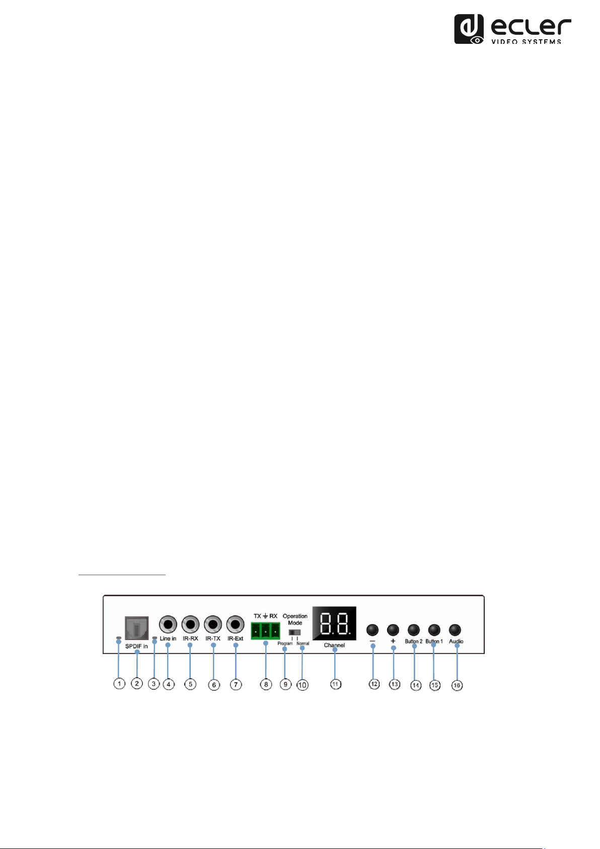
6.1.1. Front Panel
1. Not currently in use
2. Not currently in use
3. Analog audio status indicator
4. Analog audio line Input connector
7
Page 8
5. IR-RX connector for IR Sensor
6. IR-TX connector for IR Blaster
7. IR Sensor for Remote control
8. RS-232 full-duplex port
9. Program Mode: In this mode RS-232 port is used to control the unit, disabling
IR-EXT port
10. Normal Mode: In this mode RS-232 port will act as pass-through extension
11. ID Group LED display
12. ID Group DEC button
13. ID Group INC button
14. Functional button (see chapter 5.2)
15. Functional button (see chapter 5.2)
16. HDMI, S/PDIF or Analog Audio selection button: default audio selection is HDMI.
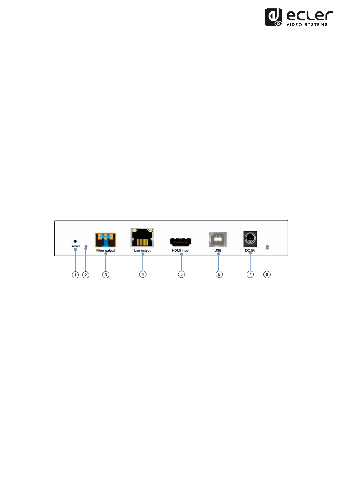
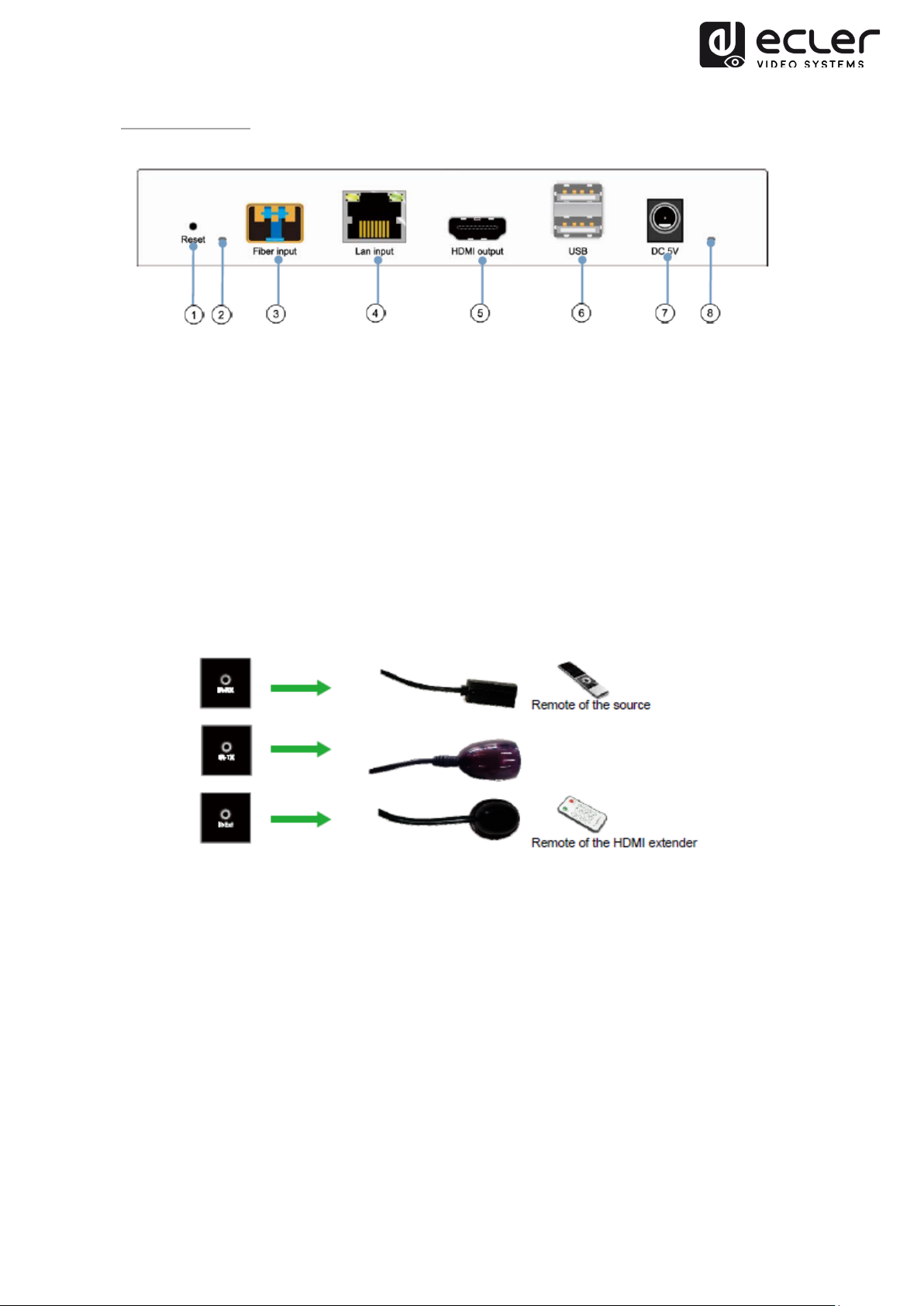
6.1.2. Transmitter Rear Panel
1. 1. Factory Reset Button
2. 2. Fiber Optic connection Indicator
3. 3. Fiber Optic SFP receptacle
4. 4. Cat5e/6 Connector
5. 5. HDMI Input Port
6. 6. USB type B input
7. 7. DC 5V Input connector
8. 8. Power supply LED Indicator
8
Page 9

6.2. Receiver
6.2.1. Front Panel
1. S/PDIF
2. S/PDIF Audio Output connector
3. Analog audio status indicator
4. Analog audio line Output connector
5. IR-RX connector for IR Sensor
6. IR-TX connector for IR Blaster
7. IR Sensor for Remote control
8. RS-232 full-duplex port
9. Program Mode: In this mode RS-232 port is used to control the unit, disabling
IR-EXT port
10. Normal Mode: In this mode RS-232 port will act as pass-through extension
11. ID Group LED display
12. ID Group DEC button
13. ID Group INC button
14. Functional button (see chapter 5.2)
15. Functional button (see chapter 5.2)
16. HDMI, S/PDIF or Analog Audio selection button: default audio selection is HDMI.
status indicator
9
Page 10
6.2.2. Rear Panel
1. Factory Reset Button
2. Fiber Optic connection Indicator
3. Fiber Optic SFP receptacle
4. Cat5e/6 Connector
5. HDMI Output Port
6. USB type A input
7. DC 5V Input connector
8. Power supply LED Indicator
6.2. IR Sensor and IR Blaster connection
10
Page 11
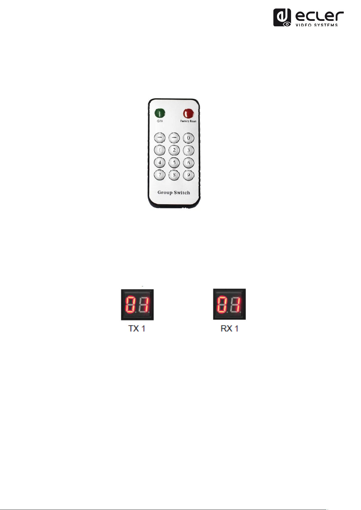
6.3. Group ID Selection with Remote Control
The Group ID can be selected using the included IR remote control. Ensure that IR-Ext
sensor is connected (refer to 5.1). The remote control can be used to change Group ID
as described below.
• When double digit ID Group number is shown, press “+” or “–” to select the Group
ID.
• Press the number keys to select the desired Group ID. For example, if you need to
change to 01, press “0”, then press“1”.
Example:
11
Page 12

6.4. Functional Buttons
Transmitter
Receiver
Button One
Button Two
Button One
Button Two
Feature
Description
Pressing this button allows to sequentially switch video
User can select between Video Mode / Graphic Mode by pressing
Link
ON/OFF
Link
Video/Graphic
Mode
Video/Graphic
Mode
streaming ON or OFF
this button. The button state is saved to the internal flash
memory, and it is restored after rebooting.
Video Mode: It automatically trades-off bandwidth and video
quality to ensure smooth video playing experience.
Graphic Mode: It will fix the trade-off to ensure best graphic/text
viewing experience.
Link
ON/OFF
7. INSTALLATION AND CONFIGURATION
7.1. Device Connection
Video/Graphic
Mode
1. Check if power supply is unplugged.
2. Connect Transmitter to video source with HDMI cable, and connect Receiver to
monitor or display with HDMI cable.
3. Connect USB cables from Transmitter to PC, and connect additional devices
such as USB mouse, USB keyboard and USB pen drive to Receiver.
4. Connect Transmitter and Receiver to Ethernet switch with network cable.
5. Power-on and activate all connected devices.
6. Power-on the Transmitter, Receiver or the PoE switch.
7. Connect the IR extension cable with Transmitter and the IR receiver cable with
Receiver for remote control.
12
Page 13
7.2. IP Address Settings and Network Requirements
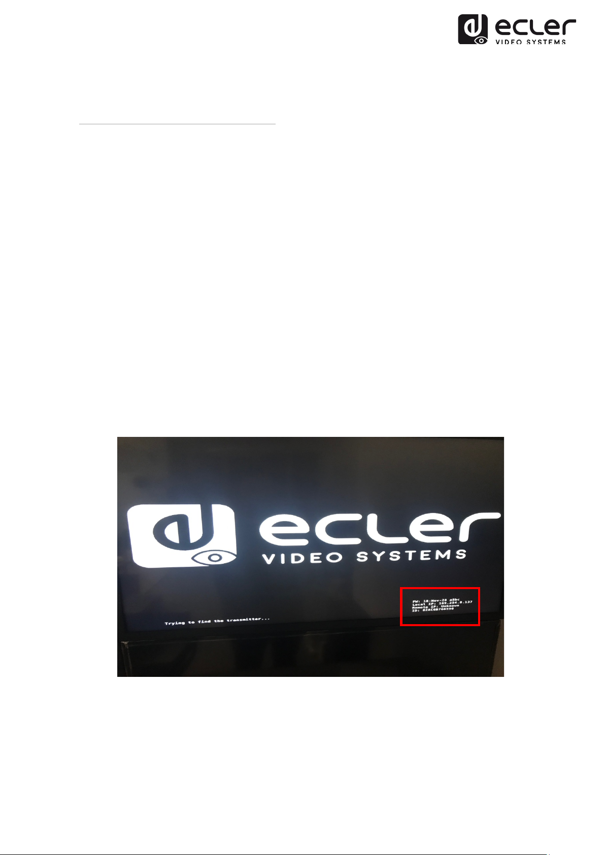
7.2.1. Auto IP Settings (Factory default)
Auto IP provides automatic IP address assignment when more devices are connected to
the same network. The default IP subnet is 169.254.x.y.
In order to discover the IP of each device, the following method can be used:
Transmitter
• Connect the TX without any HDMI input source connected to the RX. Connect
display to the RX HDMI output and select the same ID Group for both devices
using front panel buttons.
The IP address information for both devices will be displayed in the lower right
corner of the monitor. 'Local IP' is the RX IP address and 'Host IP' is the TX IP
address.
Receiver
• Connect the RX HDMI output to display. The RX will display the IP address
information in the lower right corner of the monitor. 'Local IP' is the RX IP address.
13
Page 14
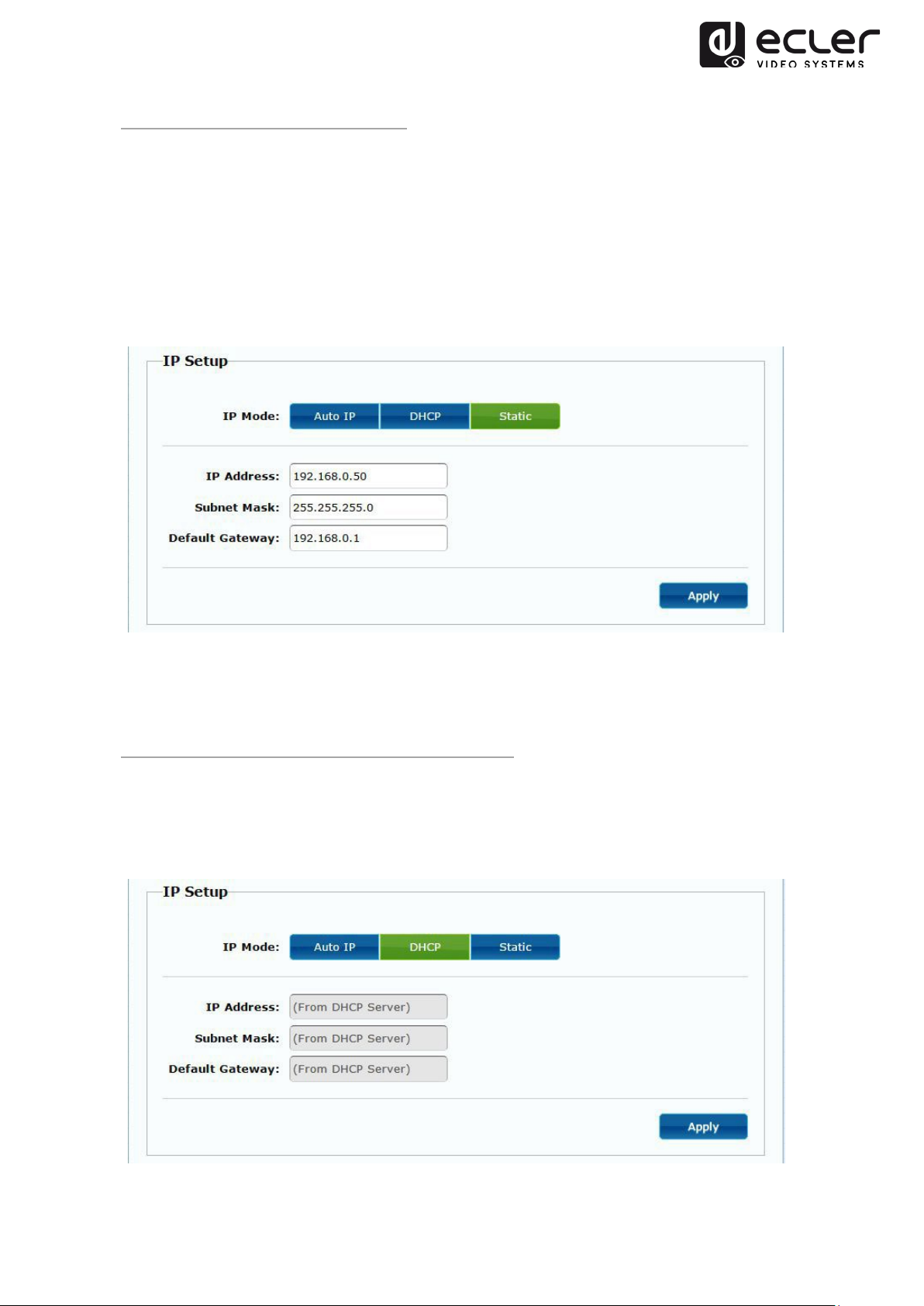
7.2.2. Static IP Address Configuration
When static IP addresses are required, the IP settings for each device need to be set
manually. After the default “Auto IP” address is discovered, as explained above, it will
be possible to open the configuration web page by typing the device IP address in a
web browser. Ensure that your PC is in the same network domain as your VEO
products.
The IP settings can be changed using the embedded web page:
After changing the default Ethernet settings, please remember to press the “Apply”
button.
7.2.3. DHCP (Dynamic Host Configuration Protocol)
If you are using switch or LAN where DHCP server is enabled, changing the IP manually
is not necessary because the DHCP server will automatically assign a unique IP address
to each device.
14
Page 15

Note: Once a factory reset is performed, the IP address settings will return to “Auto IP”.
The IP address range will be restored to “169.254.x.y”.
7.2.4. Network Requirements
Use of gigabit switches with jumbo frame and IGMP support is required and will create
the most appropriate scenario for both independent IP video networks, and cases where
IP video systems share data network. The typical data rate generated by the
Transmitters is about 300Mbps, for this reason the use of dedicated networks or VLAN
is much recommended. Ensure that the switch backplane data rate performances
exceed the ones required by your VEO system.
8. SYSTEM TOPOLOGY AND CONFIGURATION
8.1. Point-to-Point Connection (Default)
When VEO-XTI2L and VEO-XRI2L are connected as a simple extension in a point-to-
point topology, no configuration is needed. The devices have a default “Auto IP” setting
(169.254.x.x) and each Transmitter will send a unicast
corresponding Receiver by selecting the same Group ID.
video stream to the
15
Page 16

8.2. Point-to-Multipoint Connection and Operation
When VEO-XTI2L and VEO-XRI2L are connected as a distribution system in a point-to-
multipoint configuration, both Transmitters and Receivers need to be configured as
multicast
to be set to the same ID group of the Transmitter.
7.3. Multipoint-to-Multipoint Connection and Operation
When VEO-XTI2L and VEO-XRI2L are connected as over-IP matrix system in a
multipoint-to-multipoint configuration, both Transmitters and Receivers need to be
operation (please check chapter 8 and 9 of this manual). Each Receiver needs
configured as multicast
desired Transmitter ID group.
devices. Each Receiver can decode the stream related to the
16
Page 17

7.4. Billboard & Kiosk, PC to HDMI and USB Interactive Monitor
When the control of interactive video content using touch display, or KVM (Keyboard,
Mouse, Video) extensions are required, USB signal needs to be extended along with
Video signal. Please refer to chapter 9 of this manual for further instructions.
7.5. Videowall
When VEO-XTI2L and VEO-XRI2L are used as a videowall composer, the Transmitters
and Receivers need to be configured as multicast
the same Transmitter ID Group, following the instructions available in chapter 8 and 9 of
this manual.
devices. Each Receiver must be set to
The number of VEO Transmitters can’t exceed 253 units. In a class B
Network, the total number of VEO devices (Transmitters and Receivers) can’t
exceed 65K units.
Please avoid connecting or disconnecting HDMI cables while the VEO devices
are powered on!
17
Page 18

9. PC UTILITY SOFTWARE
When the PC Utility software is installed, ensure that the PC and the VEO devices are in
the same network domain. To check the devices IP please refer to chapter 6.2.
Double-click on the icon to open software:
The Device Scan Page will appear:
Press the “Start Scan” button to search for active devices on the network and select a
TX or a RX device to make changes to IP address, Host name ID, Casting Mode,
Multicast IP, IP Mode.
As factory default, both Transmitters and Receivers are configured in “Unicast” mode
and “Auto IP”.
18
Page 19

This page also allows performing a Device Reboot or a Factory Reset from remote of the
selected device.
Remember to press “Apply” after making any changes.
9.1. Mutlicast
In multipoint-to-multipoint, matrix, and videowall configuration, Transmitters and
Receivers must be set to multicast mode. Change the casting mode from Unicast to
Multicast as shown below and press Apply to confirm new settings.
19
Page 20

The ID Group of each device can be selected using software. Each ID Group
corresponds to a multicast IP address as shown below.
9.2. Videowall
In order to create a videowall composition, Transmitters and Receivers must be
configured with the same multicast IP (ID Group).
Change the “Vertical Monitor Count” and “Horizontal Monitor Count” according to the
desired Videowall size.
20
Page 21

Example: If a 2x2 videowall is required, both the first two “Wall size and Position
Layout” fields will be “2” as reported in the figure below:
When activating the “Show OSD” function, an OSD number will be assigned and
displayed on each screen. This is a useful feature to identify each Receiver and monitor.
21
Page 22

Drag and drop the selected Receiver onto the corresponding Videowall position as
shown below:
Click “Apply” to confirm.
22
Page 23

10. WEB BROWSER INTERFACE CONFIGURATION
VEO devices can also be configured using their own integrated web interface. To access
just type device IP address in a web browser (Google Chrome is recommended).
Please refer to chapter 6.2 for discovering device IP address and ensure your PC
network card is configured in the same network domain as the VEO devices.
The webpage will show 4 different configuration tabs: System, Video Wall, Network
and Functions.
10.1. System
10.1.1. Version Information and Update
The “System” tab includes “Version Information” that shows firmware version and other
information related to the product. Please contact our Ecler technical support in case of
a firmware update.
23
Page 24

10.1.2. Utilities
The Utilities tab allows to restore device to Factory Default settings and Reboot the it
from remote. It is also possible to test API Commands through the command line API
console.
24
Page 25

10.1.3. Statistics
Additional information like state of the unit, network settings, and information about
video resolution and timing are shown in this tab.
25
Page 26

10.2. Videowall
10.2.1. Basic Setup
The Videowall configuration includes Basic and Advanced setup. Under Basic setup, the
main settings for videowall composition are available. Through this page it is possible to
assign the video wall size (TX and RX must be set with the same size), screen position,
bezel and gap compensation and screen rotation or stretching.
Remember to select “This” device at the bottom of the page to control the current
device. It is possible to control several devices from the same page by selecting the
corresponding OSD/IP address as shown below.
26
Page 27

10.2.2. Bezel and Gap Compensation:
Dimensions of the screen (inside and outside width and height)
• OW: outside width
• OH: outside height
• VW: viewable width
• VH: viewable height
Please NOTE:
1. The viewable width must be lower than the outside width, and the viewable
height must be lower than the outside height.
2. If the installer doesn’t need these adjustments, just set all values to 1.
3. The unit is 0.1mm and the value must be integer.
27
Page 28

10.2.3. Wall Size and Position Layout
Select the number of vertical and/or horizontal monitors, row position and column
position. Horizontal and vertical monitor number must be set between 1 and 8.
28
Page 29

10.2.4. Preferences
Select stretching video and rotation options. The image can fit in the screen, be
stretched or be rotated at an angle of 180 or 270 degrees.
29
Page 30

10.2.5. Apply To
• All: Configure all Transmitters and Receivers in the same Group ID.
• This (Local): Configure the current device (IP address indicated in the web
browser).
• Hosts or Clients: select the Transmitter or Receiver you want to configure from
the web page in use.
• Show OSD:
Check this box to show the specific Receiver OSD number on the connected display
30
Page 31
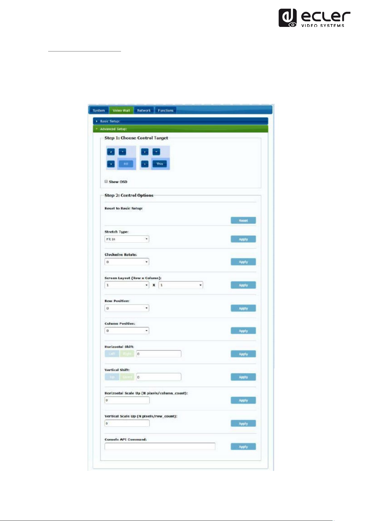
10.2.6. Advanced Setup
This session allows some additional fine adjustments. Before entering “Advanced
Setup”, please complete the “Basic Setup” in order to define and confirm videowall
layout and size.
31
Page 32

If a 3x5 videowall is required, once the basic setup is applied, the first session of
advanced setup will look like show below. It’s possible to act on a group of displays by
selecting the target devices.
In case of wrong adjustments, the Reset button will restore all the advanced parameters
to default.
32
Page 33

Video shifting and scaling can be adjusted using the following parameters:
Horizontal Shift: Adjust the video horizontal shift, Left or Right
Vertical Shift: Adjust the video vertical shift, Up or Down
33
Page 34

Horizontal Scale Up: Adjust the video horizontal scale up
Vertical Shift Scale Up: Adjust the video vertical scale up.
34
Page 35

10.3. Network
The Network page allows for adjusting network settings and casting mode for each
device.
10.3.1. Auto IP (Factory default)
Auto IP provides automatic IP address assignment when more devices are connected to
the same network. The default IP subnet is 169.254.x.y. The last two numbers are
pseudo randomly generated.
35
Page 36

10.3.2. DHCP (Dynamic Host Configuration Protocol)
If you are using switch or LAN where DHCP server is enabled, it is not necessary to set
a manual IP address, because the DHCP server will automatically assign a unique IP
address to each device.
Use instructions from Chapter 6.2 to find the IP address assigned to each device.
10.3.3. Static IP Address Configuration
When static IP addresses are required, the IP address of each device needs to be set
manually.
36
Page 37

10.3.4. Casting Mode
Select the broadcast mode according to the extender application:
• Multicast: point-to-multipoint, multipoint-to-multipoint broadcast or videowall
configuration
• Unicast: point-to-point extension
The “Auto select USB operation mode per casting mode” allows changing the USB
pass-through behaviour according to the selected casting mode. More details are
available in the next chapter.
37
Page 38

10.4. Functions
The Functions page allows configuring Video output, USB extension mode and Serial
over IP function, both for Transmitter and Receiver.
38
Page 39

10.4.1. Setup video output mode for Receiver
• Enable Video over IP: Allows to enable video extension over IP
• Enable Video Wall: Allows to enable the videowall composition function
• Enable EDID Copy: This function allows copying output EDID and passing the
information to the Transmitter. It is limited to unicast mode.
• Scaler Output Mode: Select the required scaled output mode. Select “customize”
and digit 8 Hex values for more video output resolution and refresh rate
selections.
For example:
1. 80000004: HD 720p60
2. 81000061: WXGA 1366x768@60
3. 81000040: WXGA+ 1440x900@60
4. 81000051: WUXGA 1920x1200@60
5. 8100003C: SXGA+ 1400x1050@60
…
Timeout for Detecting Video Lost: Set time for stopping the video on the output after
detecting that the transmitter HDMI signal is lost.
10.4.2. Set Scalar Output Mode for Transmitter
On the Transmitter Function page, it is possible to select the Maximum bitrate for the
generated stream.
It is possible to fix the stream bitrate to value from 10 to 200 Mbps with a Best Effort
option that optimizes the bitrate according to the video input.
39
Page 40

10.4.3. USB over IP
This section allows to select the USB extension options.
• Enable USB over IP: Check it to enable USB extension mode over IP
• Operation Mode:
o Auto select mode: will automatically select “active on link” or “active per
request” depending on the casting mode.
o Active on link: USB pass-through from transmitter to receiver.
Suggested for unicast scenarios.
o Active per request: in case of multiple KVM endpoints controlling one PC,
for example, the USB link will be activated on request. Suggested for
multicast scenarios.
• Compatibility Mode: Check it to enable USB keyboard and mouse enhanced
optimizations.
• Serial over IP
o Type 2 option will allow extending a full-duplex RS-232 communication
from Transmitter to Receiver when the RS-232 selector on the devices is
set to Normal. Other options are reserved.
Once type 2 option is selected, it will be possible to adjust the typical
serial communication parameters like baud rate, data bits, parity and stop
bits.
40
Page 41

For advanced options, please contact Ecler Technical Support.
11. FIBER OPTIC CONNECTION
When extension distances over the standard Ethernet limit of 100m are required, a
Fiber Optic link can be used instead of the Cat5e/6 copper link. The Fiber Optic link
allows reaching distances up to 2Km or 60Km, depending if multimode or single mode
fiber is used. For this purpose VEO devices support standard 3.125 Gb SFP transceiver
modules (not included).
Just insert the SFP transceiver module in the SFP receptacle to make VEO devices ready
for fiber connection. Once the fiber cable is connected and the link is active, the related
connection LED will blink, as indication of a proper operation.
12. FACTORY RESET
For these VEO devices, a Factory Reset can be performed using the PC Utility Software
(chapter
INTERFACE CONFIGURATION).
PC UTILITY SOFTWARE) or via Web page (chapter WEB BROWSER
If the IP address is unknown, please set the Operation mode selector on Program;
connect a RS-232 interface (115200, 8 N 1) and send the following command:
/ # lmparam g MY_IP
followed by CR and LF chars.
41
Page 42

13. TECHNICAL SPECIFICATIONS
Supported Resolutions 3840X2160@30HZ
3840X2160@60Hz (4:2:0) supported and
converted to 3840X2160@30Hz,
1080P/1080i/720P/576P/576i/480P/480i
Video connectors HDMI 1.4 with thread lock
HDCP 2.2 Compliant
Network requirements IGMP and Jumbo Frames compliance
Network Streaming bitrate Up to 300Mbps
Video Latency Typical 1 to 3 frames depending on network
conditions
Network connectors RJ45 with LED indication and SFP receptacle
Default IP Auto IP (169.254.x.y)
PoE power operating 802.3af
Transmission distance Up to 120m. (via CATx) in point-to-point topology;
Up to 100m when connected to standard Ethernet
devices; Up to 60Km via single mode Fiber; Up to
2Km via multi mode Fiber;
Audio Formats LPCM 2.0, Dolby True HD, DTS-HD Master audio
Sample Rate up to 192 kHz
Bitrate up to 24-bit
Analog Audio connectors 3.5mm stereo minijack
Digital Audio connectors S/PDIF Toslink
IR supported bandwidth
USB ports TX: USB 2.0 Keyboard/Mouse 1x USB type B
RS-232 connector 3-pin Phoenix
38-56 KHz
RX: USB 2.0 Keyboard/Mouse 2x USB type A
42
Page 43

Operating Temperature 0˚C - 50˚C /32˚F - 122˚F
Humidity 5 - 90% RH (no condensation)
Power Consumption 3W Maximum (TX and RX)
Power Supply AC100~240V 50/60Hz Output: DC 5V/1A
Dimensions H x W x D 26mm x 170mm x 109mm (1.02” x 6.69” x 4.29”)
(TX and RX)
Weight 470g (1.036 lbs)
43
Page 44

All product characteristics are subject to variation due to production tolerances.
NEEC AUDIO BARCELONA S.L. reserves the right to make changes or improvements in the design or
manufacturing that may affect these product specifications.
Motors, 166‐168 08038 Barcelona ‐ Spain ‐ (+34) 932238403 | information@ecler.com | www.ecler.com
44
 Loading...