

Page 1

OWNER’S MANUAL
MANUAL DE APLICACIÓN
TP-NET
Page 2

2
Page 3

TP-NET OWNER’S MANUAL
TP-NET PROTOCOL 04
NXA DIGITAL AUDIO MANAGER SERIES 07
NZA MULTICHANNEL AMPLIFIER SERIES 10
NPA STEREO AMPLIFIER SERIES 12
MIMO88 DIGITAL MATRIX 14
ERROR CODES 17
3
Page 4
TP-NET protocol (Third-Party NET)
The TP-NET protocol lets a client device get and/or set the values of several parameters of the EclerNet
compatible devices (the MIMO88 digital matrix, the NXA digital audio manager series, the NZA amplifier
series, the NPA amplifier series, etc.), like volumes, mutes, alarms, etc.
The communication with these EclerNet devices is established using Ethernet and the UDP/IP transport
protocol, always by means of the 5800 UDP port. It’s not allowed to have more than one simultaneous
access from several clients to the same EclerNet device.
A second option for this communication is using the RS-232 interface that some EclerNet compatible
devices do also have (MIMO88, NXA series, etc.). In this case, the serial connection should comply with
the following specifications:
Baud rate: 57600 (fixed, no autonegotiation)
Data bits: 8
Parity: None
Stop bits: 1
Flow control: None
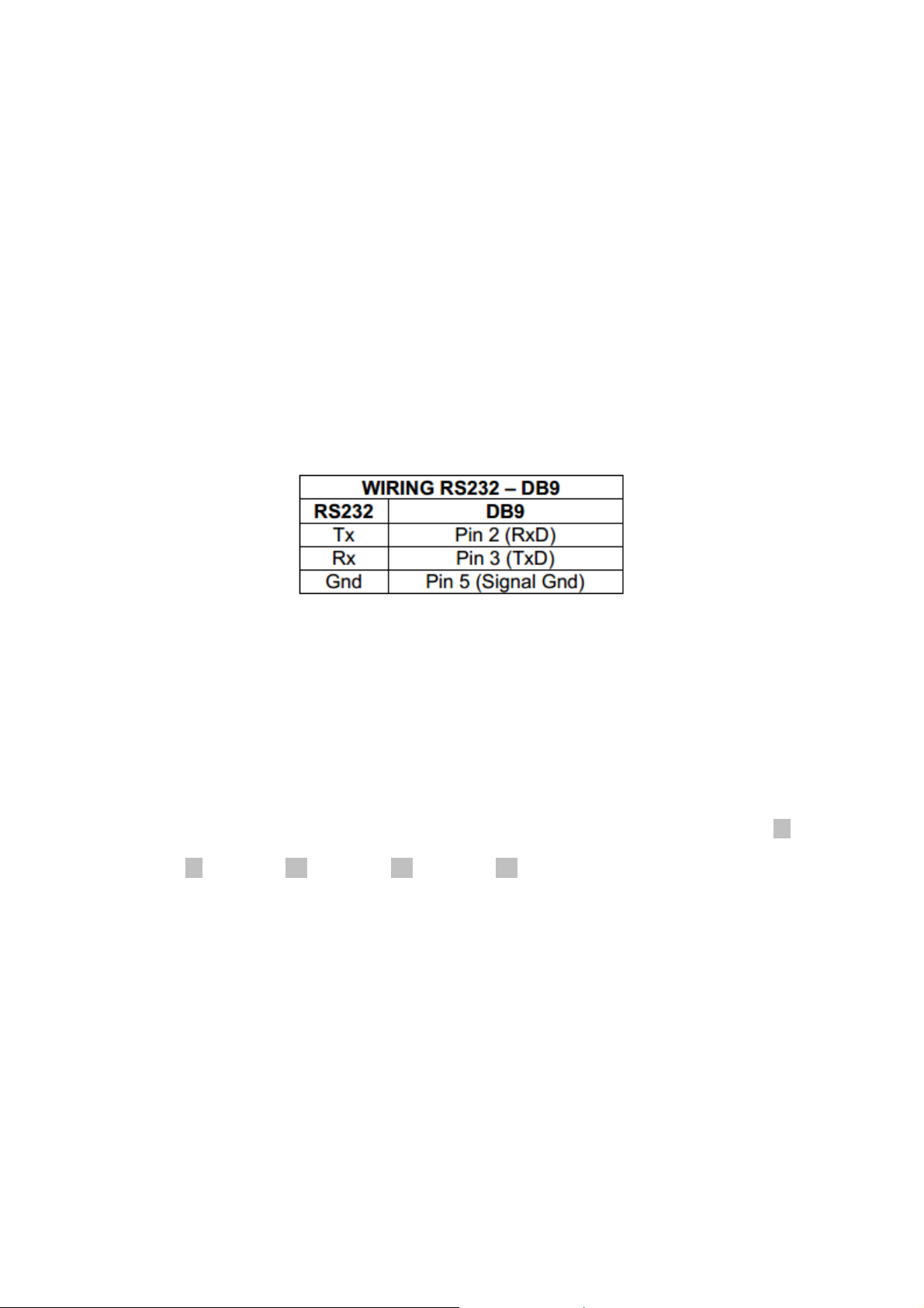
The serial cable wiring, from the device’s connector to a standard DB9 serial interface connector, should
be the following:
The protocol is simple and direct, making it easy to read, write and modify the generated code. It is
based on messages with no begin and end delimiter: each message is self-delimited by the UDP packet
size, which is defined with a maximum of 80 characters. All the messages must be written in capital
letters.
To let some control systems (like CRESTRON®, AMX®, RTI®, VITY®, MEDIALON®, etc.) process the
messages more easily, the EclerNet device adds the character LF (0x0A) to the end of each message.
This way the client can buffer the messages to process them, if it’s required. The EclerNet device can
also handle several messages received in a single message packet by using the LF delimiter.
The available messages are built with one or more fields separated with blank spaces ( = blank
space):
<TYPE> [PARAM1] [PARAM2] [PARAM3] [PARAM4][LF]
The first field (TYPE) defines the message type and then, the required parameters for it (each kind of
message requires a given number of parameters). The field TYPE can have these values:
SYSTEM
GET
SET
INC
DEC
SUBSCRIBE
UNSUBSCRIBE
DATA
ERROR
4
Page 5

At the end of this document you’ll find all the available messages and their parameters for each model of
EclerNet compatible device.
The SYSTEM, GET, SET, INC, DEC, SUBSCRIBE & UNSUBSCRIBE messages can be sent from the
client to the EclerNet device. The DATA & ERROR messages can be sent from the device to the client.
The only exception is the SYSTEM PING message, that is a SYSTEM type message that is sent from
the EclerNet device when the initial message from the client to the device was SYSTEM CONNECT
PINGPONG.
The communication (using UDP or RS-232) starts when a client sends the message SYSTEM
CONNECT to the EclerNet device. As far as the UDP communication requires no connection (unlike the
TCP), the EclerNet device stores this client’s IP address, and then uses it as the destination IP address
for the messages that it generates (DATA & ERROR). After receiving the SYSTEM CONNECT
message, the device dumps its entire configuration using several consecutive DATA messages.
The communication can be terminated by two methods:
Manually: when the client sends the SYSTEM DISCONNECT message, cancelling all the
subscriptions and stopping the DATA & ERROR messages
Automatically: in case the initial message was SYSTEM CONNECT PINGPONG and the client
didn’t get any SYSTEM PONG message in a period longer than 10 seconds (presuming a
communication breakdown)
The SET messages don’t have an automatic acknowledgement with a DATA message sent from the
EclerNet device after it has processed the SET command. The client must update the values itself and
must send the needed GET message if it requires confirmation from the device.
NOTES:
The numerical values are always integer numbers without +, –, comma or dot symbols.
[PINGPONG] is an optional parameter used to configure the device-client communication with a
periodical check, to see whether the client or the device have terminated it. When configured this
way, the device sends a SYSTEM PING once per second, and the client must answer with a
SYSTEM PONG message. If anyone doesn’t get these messages along a 10 seconds period, the
communication will be considered terminated
<Input Channel> & <Output Channel> are numerical values that identify an input or output
channel of the EclerNet device:
o It can be within a [1..8] range for MIMO88 single units (8x8 matrix masters), and [1..16] for
MIMO88 couples configured as 16x16 matrix masters
o For the NPA series, <Output Channel> can be within a [1..2] range
o For the NXA and NZA series it can be within the [1..4] or [1..6] range, for 4 or 6 channel
amplifiers
<Preset Number> is a numerical value that identifies one available Preset stored in the EclerNet
device’s memory:
o For the MIMO88 it can be within the [1..100] range
o For the NPA series it can be within the [1..10] range
o For the NXA and NZA series it can be within the [1..5] range
<Level>, <Pre Vumeter Level> y <Post Vumeter Level> are numerical values in the [0..100]
range that define values in a scale equivalent to [-inf..0] dB
<GPI> & <GPO> are numerical values within the [1..8] range for the MIMO88 configured as 8x8
matrix masters (single units), and [1..16] for MIMO88 couples configured as 16x16 matrix
5
Page 6

masters. For the NXA series GPI values can be within the [1..4] or [1..6] range, depending on
models
<GPI Value> is a numerical value within the [0..100] range that indicates the value of an
analogue GPI input. For a digital input only 0 or 100 are the possible values
<GPO Value> is a numerical value within the [0..1] range: it can only be 0 or 1 (opened or closed
GPO)
<Rate> is a numerical value within the [1..10] range that sets the VU-meter refresh rate, or the
number of times the vumeters’ values are sent (by default = 3)
“<Device Name>” is the device name inside double quotation marks, to allow for names with
blank spaces
<Error ID> is a numerical value for an error code
“<Error Description>” is a text chain inside double quotation marks, containing an error
description
6
Page 7

NXA DIGITAL AUDIO MANAGER SERIES
TYPE PARAM1 PARAM2 PARAM3 PARAM4 DESCRIPTION
SYSTEM
GET
CONNECT [PINGPONG] Saves the client IP address for responses and
then dumps current device status (with DATA
messages)
DISCONNECT Cancel subscriptions and terminates
communication
SUBSCRIPTION_RATE <Rate> Alive message from device
PING Alive message from device
PONG Alive ACK message from client
ALL Dumps current device status (with DATA
messages)
POWER Gets the Device Power status
PRESET Gets the current PRESET
OLEVEL <Output Channel> Gets the current LEVEL of an Output Channel
XLEVEL <Input Channel> <Output Channel> Gets the current LEVEL of a Matrix point
OMUTE <Output Channel> Gets the current MUTE status of an Output
Channel
XMUTE <Input Channel> <Output Channel> Gets the current MUTE status of a Matrix Point
OVU <Output Channel> Gets the VU-meter value of an Output Channel
ALARM_PROTECT <Output Channel> Gets the Protect alarm status of an Output
Channel
ALARM_FAULT <Output Channel> Gets the self-diagnosis system alarm status of
an Output Channel
INFO_NAME Gets the Device Name
INFO_MODEL Gets the Device Model
INFO_VERSION Gets the Firmware Version
INFO_MAC Gets the Device MAC address
7
Page 8

NXA DIGITAL AUDIO MANAGER SERIES
TYPE PARAM1 PARAM2 PARAM3 PARAM4 DESCRIPTION
SET
INC
DEC
SUBSCRIBE
UNSUBSCRIBE
DATA
8
POWER ON/OFF Sets the Device Power status
PRESET <Preset Number> Sets the current PRESET
OLEVEL <Output Channel> <Level> Sets the current LEVEL of an Output
Channel
XLEVEL <Input Channel> <Output Channel> Sets the current LEVEL of a Matrix
point
OMUTE <Output Channel> YES/NO Sets the current MUTE status of an
Output Channel
XMUTE <Input Channel> <Output Channel> Sets the current MUTE status of a
Matrix Point
OLEVEL <Output Channel> <Value> Increases the current LEVEL of an
Output Channel by Value (Value can
range from ±1 to ±100)
XLEVEL <Input Channel> <Output Channel> <Value> Increases the current LEVEL of a
Matrix point by Value (Value can range
from ±1 to ±100)
OLEVEL <Output Channel> <Value> Decreases the current LEVEL of an
Output Channel by Value (Value can
range from ±1 to ±100)
XLEVEL <Input Channel> <Output Channel> <Value> Decreases the current LEVEL of a
Matrix point by Value (Value can range
from ±1 to ±100)
ALL Subscribes to all VU-meters
OVU <Output Channel> Subscribes to an Output Channel VU-
meter
ALL Unsubscribe to all VU-meters
OVU <Output Channel> Unsubscribe to an Output Channel VU-
meter
POWER ON/OFF Shows the Device Power status
PRESET <Preset Number> Shows the current PRESET
OLEVEL <Output Channel> <Level> Shows the current LEVEL of an Output
Channel
XLEVEL <Input Channel> <Output Channel> <Level> Shows the current LEVEL of a Matrix
point
OMUTE <Output Channel> YES/NO Shows the current MUTE status of an
Output Channel
XMUTE <Input Channel> <Output Channel> YES/NO Shows the current MUTE status of a
Matrix point
Page 9

OVU <Output Channel> <Pre Vumeter Level> <Post Vumeter Level> Shows the VU-meter value of an
Output Channel
ALARM_PROTECT <Output Channel> ON/OFF Shows the Protect alarm status of an
Output Channel
ALARM_FAULT <Output Channel> ON/OFF Shows the self-diagnosis system alarm
status of an Output Channel
INFO_NAME “<Device Name>” Shows the Device Name
INFO_MODEL <Device Model> Shows the Device Model
INFO_VERSION <Firmware Version> Shows the Firmware Version
INFO_MAC <Device MAC
address>
ERROR
<Error ID> “<Error Description>” Informs about an error
Note: INC and DEC commands are replied with a DATA command from the device with the resulting LEVEL value, after it has been increased or decreased.
When the INC or DEC command tries to adjust a LEVEL value beyond its minimum or maximum limits, no reply (DATA command) will be produced.
Shows the Device MAC address
9
Page 10

NZA MULTICHANNEL AMPLIFIER SERIES
TYPE PARAM1 PARAM2 PARAM3 PARAM4 DESCRIPTION
SYSTEM
GET
CONNECT [PINGPONG] Saves the client IP address for responses and
then dumps current device status (with DATA
messages)
DISCONNECT Cancel subscriptions and terminates
communication
SUBSCRIPTION_RATE <Rate> Alive message from device
PING Alive message from device
PONG Alive ACK message from client
ALL Dumps current device status (with DATA
messages)
POWER Gets the Device Power status
PRESET Gets the current PRESET
OLEVEL <Output Channel> Gets the current LEVEL of an Output Channel
OMUTE <Output Channel> Gets the current MUTE status of an Output
Channel
OVU <Output Channel> Gets the VU-meter value of an Output
Channel
ALARM_PROTECT <Output Channel> Gets the Protect alarm status of an Output
Channel
INFO_NAME Gets the Device Name
INFO_MODEL Gets the Device Model
INFO_VERSION Gets the Firmware Version
INFO_MAC Gets the Device MAC address
10
Page 11

NZA MULTICHANNEL AMPLIFIER SERIES
TYPE PARAM1 PARAM2 PARAM3 PARAM4 DESCRIPTION
SET
SUBSCRIBE
UNSUBSCRIBE
DATA
ERROR
POWER ON/OFF Sets the Device Power status
PRESET <Preset Number> Sets the current PRESET
OLEVEL <Output Channel> <Level> Sets the current LEVEL of an Output
Channel
OMUTE <Output Channel> YES/NO Sets the current MUTE status of an
Output Channel
ALL Subscribes to all VU-meters
OVU <Output Channel> Subscribes to an Output Channel VU-
meter
ALL Unsubscribe to all VU-meters
OVU <Output Channel> Unsubscribe to an Output Channel VU-
meter
POWER ON/OFF Shows the Device Power status
PRESET <Preset Number> Shows the current PRESET
OLEVEL <Output Channel> <Level> Shows the current LEVEL of an Output
Channel
OMUTE <Output Channel> YES/NO Shows the current MUTE status of an
Output Channel
OVU <Output Channel> <Pre Vumeter Level> <Post Vumeter Level> Shows the VU-meter value of an
Output Channel
ALARM_PROTECT <Output Channel> ON/OFF Shows the Protect alarm status of an
Output Channel
INFO_NAME “<Device Name>” Shows the Device Name
INFO_MODEL <Device Model> Shows the Device Model
INFO_VERSION <Firmware Version> Shows the Firmware Version
INFO_MAC <Device MAC
address>
<Error ID> “<Error Description>” Informs about an error
Shows the Device MAC address
11
Page 12

NPA STEREO AMPLIFIER SERIES
TYPE PARAM1 PARAM2 PARAM3 PARAM4 DESCRIPTION
SYSTEM
GET
CONNECT [PINGPONG] Saves the client IP address for responses and then
dumps current device status (with DATA messages)
DISCONNECT Cancel subscriptions and terminates
communication
SUBSCRIPTION_RATE <Rate> Alive message from device
PING Alive message from device
PONG Alice ACK message from client
ALL Dumps current device status (with DATA
messages)
POWER Gets the Device Power status
PRESET Gets the current PRESET
OLEVEL <Output Channel> Gets the current LEVEL of an Output Channel
OMUTE <Output Channel> Gets the current MUTE status of an Output Channel
OVU <Output Channel> Gets the VU-meter value of an Output Channel
ALARM_PROTECT <Output Channel> Gets the Protect alarm status of an Output Channel
ALARM_THERMAL <Output Channel> Gets the Thermal alarm status of an Output
Channel
ALARM_LOAD <Output Channel> Gets the Load alarm status of an Output Channel
ALARM_VOLTAGE Gets the Voltage alarm status of the Device
INFO_NAME Gets the Device Name
INFO_MODEL Gets the Device Model
INFO_VERSION Gets the Firmware Version
INFO_MAC Gets the Device MAC address
12
Page 13

NPA STEREO AMPLIFIER SERIES
TYPE PARAM1 PARAM2 PARAM3 PARAM4 DESCRIPTION
SET
SUBSCRIBE
UNSUBSCRIBE
DATA
ERROR
POWER ON/OFF Sets the Device Power status
PRESET <Preset Number> Sets the current PRESET
OLEVEL <Output Channel> <Level> Sets the current LEVEL of an Output
Channel
OMUTE <Output Channel> YES/NO Sets the current MUTE status of an
Output Channel
ALL Subscribes to all VU-meters
OVU <Output Channel> Subscribes to an Output Channel VU-
meter
ALL Unsubscribe to all VU-meters
OVU <Output Channel> Unsubscribe to an Output Channel VU-
meter
POWER ON/OFF Shows the Device Power status
PRESET <Preset Number> Shows the current PRESET
OLEVEL <Output Channel> <Level> Shows the current LEVEL of an Output
Channel
OMUTE <Output Channel> YES/NO Shows the current MUTE status of an
Output Channel
OVU <Output Channel> <Pre Vumeter Level> <Post Vumeter Level> Shows the VU-meter value of an Output
Channel
ALARM_PROTECT <Output Channel> ON/OFF Shows the Protect alarm status of an
Output Channel
ALARM_THERMAL <Output Channel> ON/OFF Shows the Thermal alarm status of an
Output Channel
ALARM_LOAD <Output Channel> ON/OFF Shows the Load alarm status of an Output
Channel
ALARM_VOLTAGE ON/OFF Shows the Voltage alarm status of the
Device
INFO_NAME “<Device Name>” Shows the Device Name
INFO_MODEL <Device Model> Shows the Device Model
INFO_VERSION <Firmware Version> Shows the Firmware Version
INFO_MAC <Device MAC address> Shows the Device MAC address
<Error ID> “<Error Description>” Informs about an error
13
Page 14

MIMO88 DIGITAL MATRIX
TYPE PARAM1 PARAM2 PARAM3 PARAM4 DESCRIPTION
SYSTEM
GET
CONNECT [PINGPONG] Saves the client IP address for responses and then
dumps current device status (with DATA messages)
DISCONNECT Cancel subscriptions and terminates
communication
SUBSCRIPTION_RATE <Rate> Alive message from device
PING Alive message from device
PONG Alice ACK message from client
ALL Dumps current device status (with DATA
messages)
PRESET Gets the current PRESET
ILEVEL <Input Channel> Gets the current LEVEL of an Input Channel
OLEVEL <Output Channel> Gets the current LEVEL of an Output Channel
XLEVEL <Input Channel> <Output Channel> Gets the current LEVEL of a Matrix point
IMUTE <Input Channel> Gets the current MUTE status of an Input Channel
OMUTE <Output Channel> Gets the current MUTE status of an Output Channel
XMUTE <Input Channel> <Output Channel> Gets the current MUTE status of a Matrix Point
IVU <Input Channel> Gets the VU-meter value of an Input Channel
OVU <Output Channel> Gets the VU-meter value of an Output Channel
GPI <Input> Gets the current value of a General Purpose Input
GPO <Output> Gets the current value of a General Purpose Output
INFO_NAME Gets the Device Name
INFO_MODEL Gets the Device Model
INFO_VERSION Gets the Firmware Version
INFO_MAC Gets the Device MAC address
14
Page 15

MIMO88 DIGITAL MATRIX
TYPE PARAM1 PARAM2 PARAM3 PARAM4 DESCRIPTION
SET
INC
DEC
SUBSCRIBE
UNSUBSCRIBE
Note: INC and DEC commands are replied with a DATA command from the device with the resulting LEVEL value, after it has been increased or decreased.
When the INC or DEC command tries to adjust a LEVEL value beyond its minimum or maximum limits, no reply (DATA command) will be produced.
PRESET <Preset Number> Sets the current PRESET
ILEVEL <Input Channel> <Level> Sets the current LEVEL of an Input Channel
OLEVEL <Output Channel> <Level> Sets the current LEVEL of an Output Channel
XLEVEL <Input Channel> <Output Channel> <Level> Sets the current LEVEL for a Matrix point
IMUTE <Input Channel> YES/NO Sets the current MUTE status of an Input Channel
OMUTE <Output Channel> YES/NO Sets the current MUTE status of an Output Channel
XMUTE <Input Channel> <Output Channel> YES/NO Sets the current MUTE status for a Matrix Point
GPO <Output> <GPO Value> Sets the current value for a General Purpose Output
ILEVEL <Input Channel > <Value> Increases the current LEVEL of an Input Channel by
Value (Value can range from ±1 to ±100)
OLEVEL <Output Channel> <Value> Increases the current LEVEL of an Output Channel
by Value (Value can range from ±1 to ±100)
XLEVEL <Input Channel> <Output Channel> <Value> Increases the current LEVEL of a Matrix point by
Value (Value can range from ±1 to ±100)
ILEVEL <Input Channel > <Value> Decreases the current LEVEL of an Input Channel
by Value (Value can range from ±1 to ±100)
OLEVEL <Output Channel> <Value> Decreases the current LEVEL of an Output Channel
by Value (Value can range from ±1 to ±100)
XLEVEL <Input Channel> <Output Channel> <Value> Decreases the current LEVEL of a Matrix point by
Value (Value can range from ±1 to ±100)
ALL Subscribes to all VU-meters
IVU <Input Channel> Subscribes to an Input Channel VU-meter
OVU <Output Channel> Subscribes to an Output Channel VU-meter
ALL Unsubscribe to all VU-meters
IVU <Input Channel> Unsubscribe to an Input Channel VU-meter
OVU <Output Channel> Unsubscribe to an Output Channel VU-meter
15
Page 16

MIMO88 DIGITAL MATRIX
TYPE PARAM1 PARAM2 PARAM3 PARAM4 DESCRIPTION
DATA
ERROR
PRESET <Preset Number> Shows the current PRESET
ILEVEL <Input Channel> <Level> Shows the current LEVEL of an Input Channel
OLEVEL <Output Channel> <Level> Shows the current LEVEL of an Output
Channel
XLEVEL <Input Channel> <Output Channel> <Level> Shows the current LEVEL for a Matrix point
IMUTE <Input Channel> YES/NO Shows the current MUTE status of an Input
Channel
OMUTE <Output Channel> YES/NO Shows the current MUTE status of an Output
Channel
XMUTE <Input Channel> <Output Channel> YES/NO Shows the current MUTE status for a Matrix
Point
IVU <Input Channel> <Pre Vumeter Level> <Post Vumeter Level> Shows the VU-meter value of an Input Channel
OVU <Output Channel> <Pre Vumeter Level> <Post Vumeter Level> Shows the VU-meter value of an Output
Channel
GPI <Input> <GPI Value> Shows the current value of a General Purpose
Input
GPO <Output> <GPO Value) Shows the current value of a General Purpose
Output
INFO_NAME “<Device Name>” Shows the Device Name
INFO_MODEL <Device Model> Shows the Device Model
INFO_VERSION <Firmware Version> Shows the Firmware Version
INFO_MAC <Device MAC address> Shows the Device MAC address
<Error ID> “<Error Description>” Informs about an error
16
Page 17

ERROR CODES
ERROR ID DESCRIPTION
0
1
2
3
4
5
6
7
8
9
10
11
12
13
14
15
16
17
18
19
No Error
Invalid field TYPE
Invalid field PARAM1
Invalid field PARAM2
Invalid field PARAM3
Invalid field PARAM4
Timeout waiting for PONG
CONNECT received while connected
DISCONNECT received while unconnected
Invalid client IP (client IP different from CONNECT message)
Message too long (more than 80 characters)
Unsupported Preset number
Unsupported Message
Unsupported Input Channel number
Unsupported Output Channel number
Unsupported GPI number
Unsupported GPO number
Invalid Level value
Invalid Rate value
Invalid GPO value
17
Page 18

MANUAL DE APLICACIÓN TP-NET
PROTOCOLO TP-NET 19
AMPLIFICADORES SERIE NXA 22
AMPLIFICADORES SERIE NZA 25
AMPLIFICADORES SERIE NPA 27
MATRIZ DIGITAL MIMO88 30
CÓDIGOS DE ERROR 34
18
Page 19

Protocolo TP-NET (Third-Party NET)
El protocolo TP-NET permite a un equipo cliente consultar y modificar diversos parámetros internos de
dispositivos compatibles EclerNet (matriz digital MIMO88, gestor digital de audio serie NXA,
amplificadores serie NZA, amplificadores serie NPA, etc.), como volúmenes, mutes, alarmas, etc.
La comunicación con dichos dispositivos se realiza a través de Ethernet y usando el protocolo de
transporte UDP/IP, utilizando el puerto registrado 5800 de UDP. Sólo se permite el acceso simultáneo
de un cliente a un dispositivo EclerNet a través de este protocolo.
Una segunda opción para este tipo de comunicación pasa por el empleo de la interfaz RS-232 que
algunos dispositivos compatibles EclerNet también integran (MIMO88, NXA series, etc.). En este caso,
la comunicación debe cumplir con los siguientes requisitos:
Baud rate: 57600 (fijo, sin autonegociación)
Data bits: 8
Parity: None
Stop bits: 1
Flow control: No
El conexionado del cable entre el ordenador o dispositivo de control externo (conector serie estándar
DB9) y el dispostivo EclerNet es el siguiente:
El protocolo es simple y textual, facilitando así la lectura, escritura de código y modificación, y está
basado en mensajes, sin necesidad de delimitadores de principio y final: cada mensaje viene delimitado
de forma implícita por el tamaño del paquete UDP. Se establece un tamaño máximo de mensaje de 80
caracteres. Todos los textos deben estar escritos en letras mayúsculas.
Para facilitar el procesamiento de los mensajes en sistemas de control tipo CRESTRON®, AMX®,
RTI®, VITY®, MEDIALON®, etc., el dispositivo añade el carácter LF (0x0A) al final de cada mensaje.
De esta forma, si al programa cliente no le da tiempo a procesar los mensajes recibidos de uno en uno,
puede concatenar varios mensajes consecutivos en una única cadena de memoria (buffer) para
posteriormente volver a separarlos usando el delimitador LF.
interpretar varios mensajes recibidos en un solo paquete de datos, usando el citado delimitador.
Los mensajes están formados por uno o varios campos, todos ellos separados por espacios en blanco
( = espacio en blanco):
<TYPE> [PARAM1] [PARAM2] [PARAM3] [PARAM4][LF]
El primer campo (TYPE) define el tipo de mensaje, y por tanto el número de parámetros requeridos a
continuación (cada tipo de mensaje requiere de un determinado número de parámetros). El campo
TYPE puede tener los siguientes valores:
SYSTEM
GET
SET
INC
DEC
SUBSCRIBE
De igual forma, el dispositivo permite
19
Page 20

UNSUBSCRIBE
DATA
ERROR
En las tablas del final del documento se describen los distintos tipos de mensajes y sus
correspondientes parámetros asociados.
Los mensajes tipo SYSTEM, GET, SET, INC, DEC, SUBSCRIBE y UNSUBSCRIBE son los que pueden
ser enviados del cliente al dispositivo EclerNet, mientras que los mensajes DATA y ERROR son los
enviados del dispositivo EclerNet al cliente. Como excepción, el mensaje SYSTEM PING es el único
mensaje de tipo SYSTEM enviado por el dispositivo EclerNet si en el mensaje SYSTEM CONNECT del
cliente se especificó el parámetro opcional PINGPONG.
La comunicación (ya sea vía UDP o RS-232) se inicia cuando un cliente envía el mensaje SYSTEM
CONNECT al dispositivo EclerNet. Como la comunicación UDP es sin conexión (al contrario que la
comunicación TCP), el dispositivo EclerNet guarda la dirección IP del cliente que le envía el mensaje
SYSTEM CONNECT para usarla como destino de los mensajes generados por el propio dispositivo
(DATA y ERROR). Tras recibir el mensaje de conexión, el dispositivo EclerNet realiza un volcado de
datos (“dump”) enviando uno por uno todos los valores DATA implementados.
La comunicación se puede terminar de dos formas distintas:
Manualmente: cuando el cliente envía el mensaje SYSTEM DISCONNECT, el cual cancela
todas las subscripciones y deja de enviar DATA y ERROR
Automáticamente: si en el mensaje SYSTEM CONNECT inicial se especificó el parámetro
opcional PINGPONG y el cliente no ha recibido mensajes SYSTEM PONG durante un período
superior a 10 segundos (presumiendo pérdida de comunicación)
Los mensajes del tipo SET enviados por el cliente no tienen realimentación, es decir, el dispositivo
EclerNet no envía el mensaje DATA correspondiente tras procesar el mensaje SET. Es responsabilidad
del cliente actualizar el valor internamente con el dato enviado al dispositivo y, en caso de ser
necesario, emplear el mensaje GET correspondiente para verificar que el parámetro fue correctamente
procesado en el dispositivo.
NOTAS:
Los valores numéricos son siempre números enteros sin signo (números positivos sin decimales)
[PINGPONG] es un parámetro opcional que sirve para configurar la comunicación con el cliente
de manera que sea posible determinar si alguno de los dos ha terminado la comunicación.
Cuando se configura de esta forma, el dispositivo envía un mensaje SYSTEM PING
periódicamente (una vez por segundo) al cliente, el cual debe contestar con un mensaje
SYSTEM PONG. Si cualquiera de las partes no recibe el correspondiente mensaje en un período
de 10 segundos, se considera que la comunicación ha terminado
<Input Channel> y <Output Channel> son valores numéricos que identifican un canal de
entrada o de salida en el dispositivo EclerNet:
o Este valor puede estar en un rango [1..8] para unidades MIMO88 configuradas como
Master 8x8, y [1..16] para parejas de MIMO88 configuradas como Master 16x16
o Para los amplificadores serie NPA, <Output Channel> puede estar en el rango [1..2]
o Para los amplificadores serie NZA puede ser un número en el rango [1..4] o [1..6],
dependiendo si el modelo es de 4 o 6 canales
<Preset Number> es un valor numérico que identifica uno de los distintos Preset disponibles en
la memoria del dispositivo EclerNet:
o Para el MIMO88 este valor puede estar en el rango [1..100]
20
Page 21

o Para los amplificadores serie NPA este valor ser un número en el rango [1..10]
o Para los amplificadores serie NZA el rango es [1..5]
<Level>, <Pre Vumeter Level> y <Post Vumeter Level> son valores numéricos en el rango
[0..100] que definen valores en una escala equivalente a [-inf..0] en dB
<GPI> y <GPO> son valores numéricos el rango [1..8] para MIMO88, configurados como Master
8x8, y [1..16] para parejas de MIMO88 configuradas como Master 16x16
<GPI Value> es un valor numérico en el rango [0..100] que indica un valor de una entrada
analógica. Si la entrada es digital, los dos posibles valores serían 0 o 100
<GPO Value> es un valor numérico en el rango [0..1], es decir, sólo puede tomar los valores 0 o
1 (contacto de relé abierto o cerrado)
<Rate> es un valor numérico en el rango [1..10] que especifica la frecuencia de envío de
vúmetros al cliente, en número por segundo (por defecto = 3)
“<Device Name>” indica el nombre del dispositivo encerrado entre comillas dobles para permitir
nombres con espacios
<Error ID> es un valor numérico que codifica un tipo de error
“<Error Description>” es una cadena de texto encerrada entre comillas dobles que contiene
una descripción del error
21
Page 22

SERIE NXA
TYPE PARAM1 PARAM2 PARAM3 PARAM4 DESCRIPCIÓN
SYSTEM
GET
CONNECT [PINGPONG] Guarda la IP del cliente para las posteriores respuestas
y vuelca el estado del dispositivo con una serie de
mensajes DATA
DISCONNECT Cancela las subscripciones y termina la comunicación
SUBSCRIPTION_RATE <Rate> Mensaje periódico de dispositivo activo (frecuencia)
PING Mensaje periódico de dispositivo activo
PONG Mensaje de reconocimiento de PING desde el cliente
ALL Vuelca el estado del dispositivo con mensajes DATA
sucesivos
POWER Solicita el estado del parámetro POWER del dispositivo
(ON o OFF)
PRESET Solicita el nº de PRESET activo en el dispositivo
OLEVEL <Output
Channel>
XLEVEL <Input Channel> <Output Channel> Solicita el parámetro LEVEL (posición del control de
OMUTE <Output
Channel>
XMUTE <Input Channel> <Output Channel> Solicita el parámetro MUTE de un punto de cruce
OVU <Output
Channel>
ALARM_PROTECT <Output
Channel>
ALARM_FAULT <Output
Channel>
INFO_NAME Solicita el nombre del dispositivo
INFO_MODEL Solicita el modelo del dispositivo
INFO_VERSION Solicita la versión de Firmware del dispositivo
INFO_MAC Solicita la dirección MAC del dispositivo
Solicita el parámetro LEVEL (posición del control de
nivel) de un canal de salida
nivel) de un punto de cruce entrada-salida de la matriz
Solicita el parámetro MUTE de un canal de salida
entrada-salida de la matriz
Solicita el parámetro VUMETER (valor del VU-metro
medidor) de un canal de salida
Solicita el parámetro ALARM_PROTECT de un canal
de salida (canal en estado de protección o no)
Solicita el parámetro ALARM_FAULT de un canal de
salida (resultado del test de diagnóstico automático del
dispositivo)
22
Page 23

SERIE NXA
TYPE PARAM1 PARAM2 PARAM3 PARAM4 DESCRIPCIÓN
SET
INC
DEC
SUBSCRIBE
UNSUBSCRIBE
POWER ON/OFF Establece el estado del parámetro POWER
del dispositivo (ON o OFF)
PRESET <Preset Number> Establece (activa) un PRESET del dispositivo
(de los 5 disponibles)
OLEVEL <Output Channel> <Level> Establece el valor del parámetro LEVEL
(control de nivel) de una salida del dispositivo
XLEVEL <Input Channel> <Output Channel> Establece el valor del parámetro LEVEL
(control de nivel) de un punto de cruce
entrada-salida de la matriz
OMUTE <Output Channel> YES/NO Establece el valor del parámetro MUTE de un
canal de salida
XMUTE <Input Channel> <Output Channel> Establece el valor del parámetro MUTE de un
punto de cruce entrada-salida de la matriz
OLEVEL <Output Channel> <Value> Incrementa el valor actual del parámetro
LEVEL (control de nivel) de un canal de salida.
El incremento aplicado es el correspondiente
al parámetro Value (rango de Value de ±1 a
±100)
XLEVEL <Input Channel> <Output Channel> <Value> Incrementa el valor actual del parámetro
LEVEL (control de nivel) de un punto de cruce
entrada-salida de la matriz. El incremento
aplicado es el correspondiente al parámetro
Value (rango de Value de ±1 a ±100)
OLEVEL <Output Channel> <Value> Decrementa el valor actual del parámetro
LEVEL (control de nivel) de un canal de salida.
El incremento aplicado es el correspondiente
al parámetro Value (rango de Value de ±1 a
±100)
XLEVEL <Input Channel> <Output Channel> <Value> Decrementa el valor actual del parámetro
LEVEL (control de nivel) de un punto de cruce
entrada-salida de la matriz. El incremento
aplicado es el correspondiente al parámetro
Value (rango de Value de ±1 a ±100)
ALL Activa la suscripción a los VU-metros de todos
los canales de salida
OVU <Output Channel> Activa la suscripción al VU-metro de un canal
de salida
ALL Desactiva la suscripción a los VU-metros de
todos los canales de salida
23
Page 24

OVU <Output Channel> Desactiva la suscripción al VU-metro de un
canal de salida
DATA
POWER ON/OFF Muestra el estado del parámetro POWER del
dispositivo (ON o OFF)
PRESET <Preset Number> Muestra el nº de PRESET activo en el
dispositivo
OLEVEL <Output Channel> <Level> Muestra el parámetro LEVEL (posición del
control de nivel) de un canal de salida
XLEVEL <Input Channel> <Output Channel> <Level> Muestra el parámetro LEVEL (posición del
control de nivel) de un punto de cruce entradasalida de la matriz
OMUTE <Output Channel> YES/NO Muestra el parámetro MUTE de un canal de
salida
XMUTE <Input Channel> <Output Channel> YES/NO Muestra el parámetro MUTE de un punto de
cruce entrada-salida de la matriz
OVU <Output Channel> <Pre Vumeter Level> <Post Vumeter Level> Muestra el parámetro VUMETER (valor del
VU-metro medidor) de un canal de salida
ALARM_PROTECT <Output Channel> ON/OFF Muestra el parámetro ALARM_PROTECT de
un canal de salida (canal en estado de
protección o no)
INFO_NAME “<Device Name>” Muestra el nombre del dispositivo
INFO_MODEL <Device Model> Muestra el modelo del dispositivo
INFO_VERSION <Firmware Version> Muestra la versión de Firmware del dispositivo
INFO_MAC <Device MAC
Muestra la dirección MAC del dispositivo
address>
ERROR
<Error ID> “<Error Description>” Informa acerca de un error y su descripción
Nota: los comandos INC y DEC generan una respuesta con un comando DATA desde el dispositivo NXA, conteniendo el valor LEVEL resultante, tras haber
sido incrementado o decrementado. Cuando el comando INC o DEC intenta ajustar a un valor fuera de los límites mínimo y máximo admitidos, no se
producirá tal respuesta (no se enviará ningún comando DATA).
24
Page 25

AMPLIFICADORES SERIE NZA
TYPE PARAM1 PARAM2 PARAM3 PARAM4 DESCRIPCIÓN
SYSTEM
GET
CONNECT [PINGPONG] Guarda la IP del cliente para las posteriores respuestas
y vuelca el estado del dispositivo con una serie de
mensajes DATA
DISCONNECT Cancela las subscripciones y termina la comunicación
SUBSCRIPTION_RATE <Rate> Mensaje periódico de dispositivo activo (frecuencia)
PING Mensaje periódico de dispositivo activo
PONG Mensaje de reconocimiento de PING desde el cliente
ALL Vuelca el estado del dispositivo con mensajes DATA
sucesivos
POWER Solicita el estado del parámetro POWER del dispositivo
(ON o OFF)
PRESET Solicita el nº de PRESET activo en el dispositivo
OLEVEL <Output
Channel>
OMUTE <Output
Channel>
OVU <Output
Channel>
ALARM_PROTECT <Output
Channel>
INFO_NAME Solicita el nombre del dispositivo
INFO_MODEL Solicita el modelo del dispositivo
INFO_VERSION Solicita la versión de Firmware del dispositivo
INFO_MAC Solicita la dirección MAC del dispositivo
Solicita el parámetro LEVEL (posición del control de
nivel) de un canal de salida
Solicita el parámetro MUTE de un canal de salida
Solicita el parámetro VUMETER (valor del VU-metro
medidor) de un canal de salida
Solicita el parámetro ALARM_PROTECT de un canal
de salida (canal en estado de protección o no)
25
Page 26

AMPLIFICADORES SERIE NZA
TYPE PARAM1 PARAM2 PARAM3 PARAM4 DESCRIPCIÓN
SET
SUBSCRIBE
UNSUBSCRIBE
DATA
ERROR
POWER ON/OFF Establece el estado del parámetro POWER
del dispositivo (ON o OFF)
PRESET <Preset Number> Establece (activa) un PRESET del dispositivo
(de los 5 disponibles)
OLEVEL <Output Channel> <Level> Establece el valor del parámetro LEVEL
(control de nivel) de una salida del dispositivo
OMUTE <Output Channel> YES/NO Establece el valor del parámetro MUTE de un
canal de salida
ALL Activa la suscripción a los VU-metros de todos
los canales de salida
OVU <Output Channel> Activa la suscripción al VU-metro de un canal
de salida
ALL Desactiva la suscripción a los VU-metros de
todos los canales de salida
OVU <Output Channel> Desactiva la suscripción al VU-metro de un
canal de salida
POWER ON/OFF Muestra el estado del parámetro POWER del
dispositivo (ON o OFF)
PRESET <Preset Number> Muestra el nº de PRESET activo en el
dispositivo
OLEVEL <Output Channel> <Level> Muestra el parámetro LEVEL (posición del
control de nivel) de un canal de salida
OMUTE <Output Channel> YES/NO Muestra el parámetro MUTE de un canal de
salida
OVU <Output Channel> <Pre Vumeter Level> <Post Vumeter Level> Muestra el parámetro VUMETER (valor del
VU-metro medidor) de un canal de salida
ALARM_PROTECT <Output Channel> ON/OFF Muestra el parámetro ALARM_PROTECT de
un canal de salida (canal en estado de
protección o no)
INFO_NAME “<Device Name>” Muestra el nombre del dispositivo
INFO_MODEL <Device Model> Muestra el modelo del dispositivo
INFO_VERSION <Firmware Version> Muestra la versión de Firmware del dispositivo
INFO_MAC <Device MAC
address>
<Error ID> “<Error Description>” Informa acerca de un error y su descripción
Muestra la dirección MAC del dispositivo
26
Page 27

AMPLIFICADORES SERIE NPA
TYPE PARAM1 PARAM2 PARAM3 PARAM4 DESCRIPCIÓN
SYSTEM
GET
CONNECT [PINGPONG] Guarda la IP del cliente para las posteriores
respuestas y vuelca el estado del dispositivo con una
serie de mensajes DATA
DISCONNECT Cancela las subscripciones y termina la comunicación
SUBSCRIPTION_RATE <Rate> Mensaje periódico de dispositivo activo (frecuencia)
PING Mensaje periódico de dispositivo activo
PONG Mensaje de reconocimiento de PING desde el cliente
ALL Vuelca el estado del dispositivo con mensajes DATA
sucesivos
POWER Solicita el estado del parámetro POWER del
dispositivo (ON o OFF)
PRESET Solicita el nº de PRESET activo en el dispositivo
OLEVEL <Output Channel> Solicita el parámetro LEVEL (posición del control de
nivel) de un canal de salida
OMUTE <Output Channel> Solicita el parámetro MUTE de un canal de salida
OVU <Output Channel> Solicita el parámetro VUMETER (valor del VU-metro
medidor) de un canal de salida
ALARM_PROTECT <Output Channel> Solicita el parámetro ALARM_PROTECT de un canal
de salida (canal en estado de protección o no)
ALARM_THERMAL <Output Channel> Solicita el parámetro ALARM_THERMAL de un canal
de salida (canal en estado de alarma térmica o no)
ALARM_LOAD <Output Channel> Solicita el parámetro ALARM_LOAD de un canal de
salida (alarma de impedancia de carga medida en el
canal fuera del rango establecido o no)
ALARM_VOLTAGE Solicita el parámetro ALARM_VOLTAGE de un canal
de salida (la alarma de tensión AC de alimentación se
halla activa (la tensión AC excede el máximo
establecido) o no)
INFO_NAME Solicita el nombre del dispositivo
INFO_MODEL Solicita el modelo del dispositivo
INFO_VERSION Solicita la versión de Firmware del dispositivo
INFO_MAC Solicita la dirección MAC del dispositivo
27
Page 28

AMPLIFICADORES SERIE NPA
TYPE PARAM1 PARAM2 PARAM3 PARAM4 DESCRIPCIÓN
SET
SUBSCRIBE
UNSUBSCRIBE
POWER ON/OFF Establece el estado del parámetro POWER del
dispositivo (ON o OFF)
PRESET <Preset Number> Establece (activa) un PRESET del dispositivo (de los
5 disponibles)
OLEVEL <Output Channel> <Level> Establece el valor del parámetro LEVEL (control de
nivel) de una salida del dispositivo
OMUTE <Output Channel> YES/NO Establece el valor del parámetro MUTE de un canal
de salida
ALL Activa la suscripción a los VU-metros de todos los
canales de salida
OVU <Output Channel> Activa la suscripción al VU-metro de un canal de
salida
ALL Desactiva la suscripción a los VU-metros de todos los
canales de salida
OVU <Output Channel> Desactiva la suscripción al VU-metro de un canal de
salida
28
Page 29

AMPLIFICADORES SERIE NPA
TYPE PARAM1 PARAM2 PARAM3 PARAM4 DESCRIPCIÓN
DATA
ERROR
POWER ON/OFF Muestra el estado del parámetro POWER del
dispositivo (ON o OFF)
PRESET <Preset Number> Muestra el nº de PRESET activo en el dispositivo
OLEVEL <Output Channel> <Level> Muestra el parámetro LEVEL (posición del control
de nivel) de un canal de salida
OMUTE <Output Channel> YES/NO Muestra el parámetro MUTE de un canal de salida
OVU <Output Channel> <Pre Vumeter
Level>
ALARM_PROTECT <Output Channel> ON/OFF Muestra el parámetro ALARM_PROTECT de un
ALARM_THERMAL <Output Channel> ON/OFF Muestra el parámetro ALARM_THERMAL de un
ALARM_LOAD <Output Channel> ON/OFF Muestra el parámetro ALARM_LOAD de un canal
ALARM_VOLTAGE ON/OFF Muestra el parámetro ALARM_VOLTAGE de un
INFO_NAME “<Device Name>” Muestra el nombre del dispositivo
INFO_MODEL <Device Model> Muestra el modelo del dispositivo
INFO_VERSION <Firmware Version> Muestra la versión de Firmware del dispositivo
INFO_MAC <Device MAC
address>
<Error ID> “<Error Description>” Informa acerca de un error y su descripción
Muestra la dirección MAC del dispositivo
<Post Vumeter Level> Muestra el parámetro VUMETER (valor del VU-
metro medidor) de un canal de salida
canal de salida (canal en estado de protección o
no)
canal de salida (canal en estado de alarma
térmica o no)
de salida (alarma de impedancia de carga medida
en el canal fuera del rango establecido o no)
canal de salida (la alarma de tensión AC de
alimentación se halla activa (la tensión AC excede
el máximo establecido) o no)
29
Page 30

MATRIZ DIGITAL MIMO88
TYPE PARAM1 PARAM2 PARAM3 PARAM4 DESCRIPCIÓN
SYSTEM
GET
CONNECT [PINGPONG] Guarda la IP del cliente para las posteriores
respuestas y vuelca el estado del dispositivo con
una serie de mensajes DATA
DISCONNECT Cancela las subscripciones y termina la
comunicación
SUBSCRIPTION_RATE <Rate> Mensaje periódico de dispositivo activo (frecuencia)
PING Mensaje periódico de dispositivo activo
PONG Mensaje de reconocimiento de PING desde el
cliente
ALL Vuelca el estado del dispositivo con mensajes
DATA sucesivos
PRESET Solicita el nº de PRESET activo en el dispositivo
ILEVEL <Input Channel> Solicita el parámetro LEVEL (posición del control
de nivel) de un canal de entrada
OLEVEL <Output Channel> Solicita el parámetro LEVEL (posición del control
de nivel) de un canal de salida
XLEVEL <Input Channel> <Output Channel> Solicita el parámetro LEVEL (posición del control
de nivel) de un punto de cruce entrada-salida de la
matriz
IMUTE <Input Channel> Solicita el parámetro MUTE de un canal de entrada
OMUTE <Output Channel> Solicita el parámetro MUTE de un canal de salida
XMUTE <Input Channel> <Output Channel> Solicita el parámetro MUTE de un punto de cruce
entrada-salida de la matriz
IVU <Input Channel> Solicita el parámetro VUMETER (valor del VU-
metro medidor) de un canal de entrada
OVU <Output Channel> Solicita el parámetro VUMETER (valor del VU-
metro medidor) de un canal de salida
GPI <Input> Solicita el valor de una entrada GPI (General
Purpose Input)
GPO <Output> Solicita el valor de una salida GPO (General
Purpose Output)
INFO_NAME Solicita el nombre del dispositivo
INFO_MODEL Solicita el modelo del dispositivo
INFO_VERSION Solicita la versión de Firmware del dispositivo
INFO_MAC Solicita la dirección MAC del dispositivo
30
Page 31

MATRIZ DIGITAL MIMO88
TYPE PARAM1 PARAM2 PARAM3 PARAM4 DESCRIPCIÓN
SET
INC
DEC
PRESET <Preset Number> Establece (activa) un PRESET del dispositivo (de los
5 disponibles)
ILEVEL <Input Channel> <Level> Establece el valor del parámetro LEVEL (control de
nivel) de una entrada del dispositivo
OLEVEL <Output Channel> <Level> Establece el valor del parámetro LEVEL (control de
nivel) de una salida del dispositivo
XLEVEL <Input Channel> <Output Channel> <Level> Establece el valor del parámetro LEVEL (control de
nivel) de un punto de cruce entrada-salida de la
matriz
IMUTE <Input Channel> YES/NO Establece el estado del parámetro MUTE de un
canal de entrada del dispositivo
OMUTE <Output Channel> YES/NO Establece el estado del parámetro MUTE de un
canal de salida del dispositivo
XMUTE <Input Channel> <Output Channel> YES/NO Establece el valor del parámetro MUTE de un punto
de cruce entrada-salida de la matriz
GPO <Output> <GPO Value> Establece el valor de una salida GPO (General
Purpose Output)
ILEVEL <Input Channel > <Value> Incrementa el valor actual del parámetro LEVEL
(control de nivel) de una entrada del dispositivo. El
incremento aplicado es el correspondiente al
parámetro Value (rango de Value de ±1 a ±100)
OLEVEL <Output Channel> <Value> Incrementa el valor actual del parámetro LEVEL
(control de nivel) de una salida del dispositivo. El
incremento aplicado es el correspondiente al
parámetro Value (rango de Value de ±1 a ±100)
XLEVEL <Input Channel> <Output Channel> <Value> Incrementa el valor actual del parámetro LEVEL
(control de nivel) de un punto de cruce entradasalida de la matriz del dispositivo. El incremento
aplicado es el correspondiente al parámetro Value
(rango de Value de ±1 a ±100)
ILEVEL <Input Channel > <Value> Decrementa el valor actual del parámetro LEVEL
(control de nivel) de una entrada del dispositivo. El
decremento aplicado es el correspondiente al
parámetro Value (rango de Value de ±1 a ±100)
OLEVEL <Output Channel> <Value> Decrementa el valor actual del parámetro LEVEL
(control de nivel) de una salida del dispositivo. El
decremento aplicado es el correspondiente al
parámetro Value (rango de Value de ±1 a ±100)
31
Page 32

XLEVEL <Input Channel> <Output Channel> <Value> Decrementa el valor actual del parámetro LEVEL
(control de nivel) de un punto de cruce entradasalida de la matriz del dispositivo. El decremento
aplicado es el correspondiente al parámetro Value
(rango de Value de ±1 a ±100)
SUBSCRIBE
ALL Activa la suscripción a todos los VU-metros
IVU <Input Channel> Activa la suscripción al VU-metro de un canal de
entrada
OVU <Output Channel> Activa la suscripción al VU-metro de un canal de
salida
UNSUBSCRIBE
ALL Desactiva la suscripción a todos los VU-metros
IVU <Input Channel> Desactiva la suscripción al VU-metro de un canal de
entrada
OVU <Output Channel> Desactiva la suscripción al VU-metro de un canal de
salida
Nota: los comandos INC y DEC generan una respuesta con un comando DATA desde el dispositivo NXA, conteniendo el valor LEVEL resultante, tras haber
sido incrementado o decrementado. Cuando el comando INC o DEC intenta ajustar a un valor fuera de los límites mínimo y máximo admitidos, no se
producirá tal respuesta (no se enviará ningún comando DATA).
32
Page 33

MATRIZ DIGITAL MIMO88
TYPE PARAM1 PARAM2 PARAM3 PARAM4 DESCRIPCIÓN
DATA
ERROR
PRESET <Preset Number> Muestra el nº de PRESET activo en el
dispositivo
ILEVEL <Input Channel> <Level> Muestra el parámetro LEVEL (posición del
control de nivel) de un canal de entrada
OLEVEL <Output Channel> <Level> Muestra el parámetro LEVEL (posición del
control de nivel) de un canal de salida
XLEVEL <Input Channel> <Output Channel> <Level> Muestra el valor del parámetro LEVEL (control
de nivel) de un punto de cruce entrada-salida
de la matriz
IMUTE <Input Channel> YES/NO Muestra el parámetro MUTE de un canal de
entrada
OMUTE <Output Channel> YES/NO Muestra el parámetro MUTE de un canal de
salida
XMUTE <Input Channel> <Output Channel> YES/NO Muestra el valor del parámetro MUTE de un
punto de cruce entrada-salida de la matriz
IVU <Input Channel> <Pre Vumeter Level> <Post Vumeter Level> Muestra el parámetro VUMETER (valor del VU-
metro medidor) de un canal de entrada
OVU <Output Channel> <Pre Vumeter Level> <Post Vumeter Level> Muestra el parámetro VUMETER (valor del VU-
metro medidor) de un canal de salida
GPI <Input> <GPI Value> Solicita el valor de una entrada GPI (General
Purpose Input)
GPO <Output> <GPO Value> Solicita el valor de una salida GPO (General
Purpose Output)
INFO_NAME “<Device Name>” Solicita el nombre del dispositivo
INFO_MODEL <Device Model> Solicita el modelo del dispositivo
INFO_VERSION <Firmware Version> Solicita la versión de Firmware del dispositivo
INFO_MAC <Device MAC address> Solicita la dirección MAC del dispositivo
<Error ID> “<Error Description>” Informa acerca de un error y su descripción
33
Page 34

CÓDIGOS DE ERROR
ERROR ID DESCRIPCIÓN
0
1
2
3
4
5
6
7
8
9
10
11
12
13
14
15
16
17
18
19
No Error
Campo TYPE inválido
Campo PARAM1 inválido
Campo PARAM2 inválido
Campo PARAM3 inválido
Campo PARAM4 inválido
Tiempo de espera de PONG agotado (“time-out”)
CONNECT recibido estando previamente conectado
DISCONNECT recibido estando previamente desconectado
Cliente IP inválido (cliente IP diferente del establecido en el mensaje CONNECT)
Mensaje demasiado largo (más de 80 caracteres)
Número de PRESET no soportado
Mensaje no soportado
Número de canal de entrada no soportado
Número de canal de salida no soportado
Número de canal de GPI no soportado
Número de canal de GPO no soportado
Valor LEVEL inválido
Valor RATE inválido
Valor GPO inválido
34
Page 35

50.0216.01.01
ECLER Laboratorio de electro-acústica S.A.
Motors 166-168, 08038 Barcelona, Spain
INTERNET http://www.ecler.com e-mail: info@ecler.es
 Loading...