

USER MANUAL
MANUAL DE INSTRUCCIONES
MANUEL UTILISATEUR
BEDIENUNGSANLEITUNG
PROFESSIONAL AUDIO CONTROLLER
PEAK
PFL ON
FX SEND
MIX
XFA XFB
OFF
BASS
+10
OFF
MID
+10
0
PFL ONPFL ON
FX SEND FX SEND
BASS
OFF +10
MID
OFF +10
0
BASS
OFF +10
MID
OFF +10
0
TREBLE
OFF +10
0
-200+20
PHONOSPH-LINE
0
PEAK
TREBLE
OFF +10
0
-200+20
TREBLE
OFF +10
0
-200+20
PROFESSIONAL AUDIO CONTROLLER
PHONOSPL-LINE
0
PEAK
PHONOSPH-LINE
0
XF OFF
CUT IN
REVERSE SWITCH
TALKOVER ON
NORMAL
XFADER
FADE
VOL
0 10
MONITOR
PFL MIX
PFL ONPFL ON
FX SEND
XFA
MIX
XFB
0
VOL
10
MIX XFB
FX SEND
BASS
OFF +10
MID
OFF0+10
OFF
BASS
+10
OFF
MID
0
+10
PEAK
H-LINE
TREBLE
OFF0+10
-200+20
OFF
TREBLE
0
+10
-200+20
PEAK
L-LINEPHONO
SP
0
L-LINE
MIC ATT.
SP
0
MIC REC 2
1
0
2
4
3
5
7
6
8
10
9
A
B
FADE CURVE
SOFT SHARP
6
2
0
1
5
3
4
9
8
7
10
6
2
0
1
5
3
4
9
8
7
10
6
2
0
1
5
3
4
9
8
7
10
10
D
Y
R
0 10
Pitch Shifter
FX CUE
FX INPUT
Flanger Echo
Echo Reverb
Filtered Echo
High Pass Filter
L+R
Phaser
Vocoder
Flanger
Reverb
Delay
Low Pass Filter
L.F.O. Filter
MASTER 1
0
W
FX LAUNCH
T
E
TAP
SELECT
REF.
PARAMETER
TIME
EFFECT
MASTER 2
0 10
PFL
L+R
+2
L
-10
-38
-30
-20
-7
-4
-2
0
BAL
R
C
+4
+7
+10
+2
-38
-30
-20
-10
L R
-7
-4
-2
0
MASTER
+4
+7
+10


3
User Manual Contents
1. IMPORTANT REMARK 004
Safety Instructions 004
Warranty description 004
2. INTRODUCTION 005
3. INSTALLATION 005
3.1 Audio input connections 006
3.2 Audio outputs connections 007
3.3 Digital connections 008
4. QUICK START 009
5. OPERATION AND USAGE MANUAL 010
5.1 Start-up 010
5.2 Control Description 010
6. EFFECT PERFORMANCE 013
6.1 Mixer effect controls 013
6.2 Effect description 016
7. PC MODE – EFFECT REMOTE PARAMETERING 021
7.1 Drivers and Software installation 021
7.2 PC Mode operation and usage 022
8. MIDI USAGE 029
9. FURTHER CONSIDERATIONS 029
10. FUNCTION LIST 030
11. FUNCTION DIAGRAM 031
12. TECHNICAL CHARACTERISTICS 122
13. DIAGRAMS 123
13.1 Figures 123
13.1.1 Connection diagram 123
13.1.2 Rack ear system 124
13.1.3 Internal jumper configuration 125
14. BLOC DIAGRAM 126
All numbers subject to variation due to production tolerances. ECLER S.A. reserves the right to make changes or improvements in
manufacturing or design which may affect specifications.

4
1. IMPORTANT REMARK
Safety Instructions
In order to get the optimum operation and efficiency from your mixing unit, it is VERY IMPORTANT - before you
plug anything - to read this manual very carefully and take seriously into account all considerations specified within
it. We strongly recommend that its maintenance be carried out by our Authorised Technical Services.
This apparatus must be earthed through its mains cable.
Do not expose the unit to rain or water splashes, and do not place liquid containers or incandescent
objects like candles on top of the unit. Do not obstruct the ventilation shafts with any kind of material.
Any change in the configuration of the unit must be carried out by a qualified technician. Should any
connection / disconnection task be done, always disconnect the unit from the mains supply.
Warranty Descriptions
Your ECLER equipment has undergone exhaustive laboratory and quality control tests before leaving the factory.
Nevertheless, your may be in need of our Technical Service during the period covered by the Guarantee or
afterwards. In that case, carefully protect your equipment in its original packet and send it to our Technical Service
with the transport and insurance paid. Attach a photocopy of your Guarantee Certificate and a detailed description
of the defect you have observed.
ECLER, S.A. guarantees its ECLER products against material or fabrication defects for a ONE-YEAR period (3
YEAR period in SCLAT and NUO series mixers and in the SPM technology amplifiers and 5 YEAR in the
ETERNAL potentiometers) after the date of original purchase.
ECLER, S.A., will repair the defective equipment within the aforementioned period, with no charge for parts and
labour.
To ensure the validity of the Guarantee, it is essential that the attached Guarantee, Registration Card is filled out
correctly and remitted to your ECLER distributor, within 10 DAYS after date of purchase.
The Guarantee is non-transferrable and protects the original buyer only.
The Guarantee does not cover:
Damages caused by mistreatment or negligent handling, lack of elementary precautions, disregard to the
instructions in the manual, faulty connection or accidents.
ECLER, S.A., will not be held responsible for any direct or indirect damage, loss or other damage originated by or
relating to the set.
* sets that have been manipulated, altered or repaired other than at the authorized Technical Service centers.
* the exterior fittings and electro-mechanical parts, nor their wear due to use.
* shipping and insurance expenses, nor for damages the set may incur during its transport.
This Guaranteed is valid only for repairs or services carried out at an authorized Technical Service Center.

5
2. INTRODUCTION
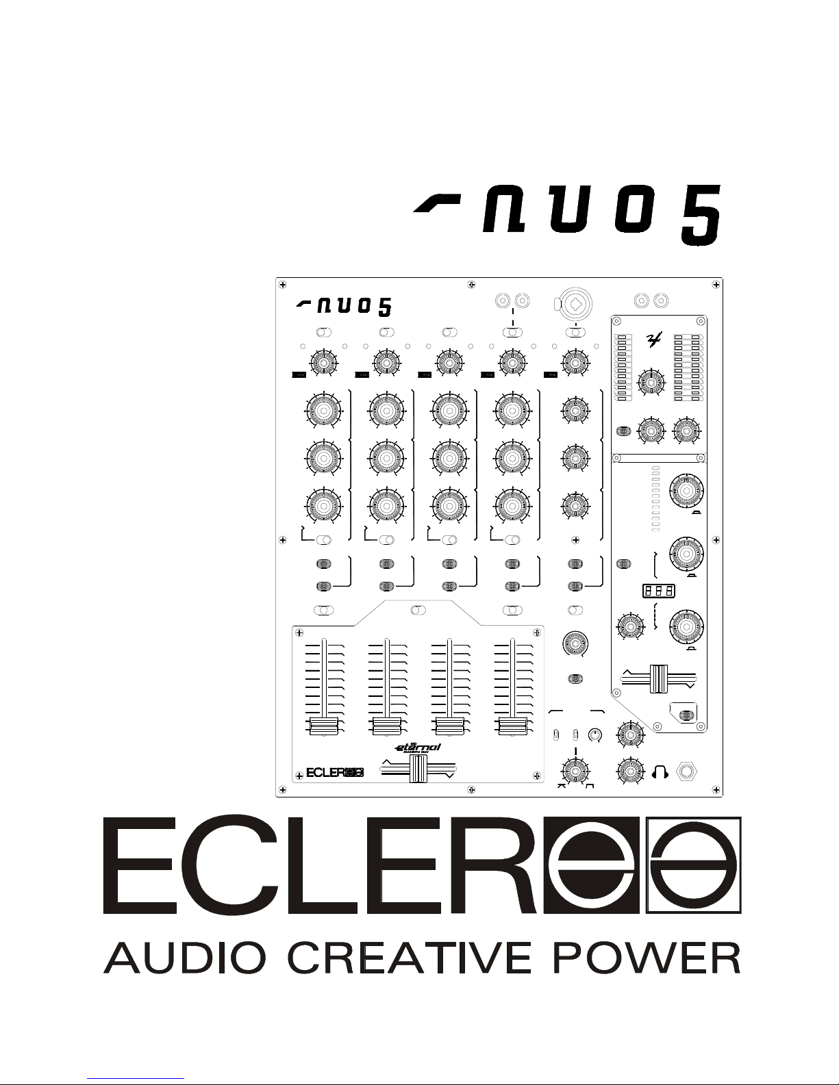
Congratulations! You are the owner of a genuine ECLER professional equipment. The NUO5 has been carefully
designed in collaboration with leading dj performers and advance music producers, developed with the highest
quality components, and manufactured in-house (Barcelona-Spain) under strict quality controls.
The NUO5 is a five stereo channel mixer that integrates a digital effect processor remotely programmable through
the edi:lab PC Software. The console also features the award winning ETERNAL Inductive Crossfader, a very
precise contactless crossfade concept using an exclusive magnetic field system.
The NUO5 is mainly dedicated to Club use because of its format and robustness, but its software control, MIDI
functions and ETERNAL crossfader make it a perfect studio tool and/or performance mixer.
3. INSTALLATION
The first thing to take into consideration when placing your NUO5 is your comfort and an easy access to all the
connections. The NUO5 is basically conceived as a tabletop mixer and its usual placement will be between two
vinyls or CD players. The mixer has a 14.57’’ (37cm) depth and 12.6’’ (32cm) width format. The optional metallic
side profiles kit allows you to firmly fix your mixer to the surface over which it is placed or over its own profiles
(Fig.1). These profiles also allow to tilt the mixer's position for an easier operation.
Because of the high gain of the PHONO and MICROPHONE inputs, always try to place the mixer as far away as
possible from noise sources (dimmers, engines, etc.) and mains wires. For the very same reason, and under any
circumstance, you should never remove the unit's metallic cover.
The power consumption of the NUO5 is very low, so they do not need any cooling, but you should avoid extreme
temperatures and the atmosphere should be as dry and dust free as possible.
The NUO5 operates now with a new universal input power supply “Switching Power Supply” and can perfectly
works without any internal modification from 90V to 264V – 47 to 63Hz. Make sure that the mains -wire is far away
from the signal-cables in order to avoid any possible audio hum.
In order to protect the unit from an eventual electrical overload it carries a T 500 mA fuse. Should it ever blow up,
unplug the unit from mains and replace it with an identical one. If the new fuse blows again contact immediately
with our authorized technical service.
ATTENTION: NEVER SHORT-CIRCUIT THE SECURITY PATH NOR USE A HIGHER VALUE FUSE.
CAUTION: Fuse substitutions have to be performed by a qualified technician.

6
3.1 Audio input connections
Phono 1 Turntable 1
H-Line 1 CD Deck 1
Phono 2 Turntable 2
L-Line 2 Sequencer
Phono 3 Turntable 3
H-Line 3 CD Deck 2
Phono 4 Turntable 4
L-Line Top 4 MP3/Minidisc player
L-Line Rear 4 Computer
Mic Att. 5 High Sensitivity Microphone
Mic 5 Microphone
H-Line 5 DAT Player
- Phono Inputs:
Phono Turntables must be fitted with a magnetic cartridge with nominal output level between - 60dBV and -20dBV
(1 to 100 mV). The PHONO inputs (42) of the NUO5 have a high headroom (margin before saturation) and it can
handle higher output cartridges than what is usual. These inputs are supplied with a nominal input sensitivity of
-40dBV(10mV).
- Line Inputs:
Given the important level differences between usual LINE and CD sources, the NUO5 provides specialized inputs
for each source. The sensitivity of the HIGH LINE (43) input is 0dBV (1V), while the LOW LINE (44) sensitivity is
-10dBV(316mV). CD Players, DAT, MP3, and DVD Audio should be connected to the HIGH LINE input. Tape
players, tuners and some production devices (samplers, sequencers) should be connected to the LOW LINE input.
- Microphone Inputs:
The MIC input (40) is ready for a nominal input level of -50dBV (3.16 mV) and is equipped with a combo
JACK/XLR3 connectors. These inputs provide, placing the input selector on ATT position, an input sensitivity
reduction of 20dB which allows a nominal level change from -50 to -30dBV (3.16 to 31.6mV). The connection of
balanced signals is as follows:
Hot or direct signal > Pin 2 Tip
Cold or inverted signal > Pin 3 Ring
Ground > Pin 1 Sleeve
Low impedance (200 to 600Ω) monophonic microphones must be used. In case of working with an unbalanced
connection Pin 1 and Pin 3 must be short-circuited. The NUO5 features a Phantom power supply for the connection
of condenser microphones. A set of internal jumpers allow you to inhibit the phantom power for the microphone.
The default setting of these jumpers on the NUO5 is "Phantom ON". See configuration diagram.

7
3.2 Audio outputs connections
Out 1 Main power amplifier
Out 2 Booth/Room2 power amplifier
Recording top Recording device 1
Recording rear Recording device 2
External Loop External effect device
(Send and Return) (Input and Output)
Headphones Headphones
- Master Output 1:
These stereo outputs feed the main house P.A. system through a XLR3 Balanced connections. The OUT 1 (48/49)
level is set at 0dBV (1V) but can be changed to +6dBV (2V) through soldering bridges. OUT 1 is controlled by
MASTER 1 (35) level potentiometer.
Nearby the MASTER 1 control, a R+L button (34) sums both Right and Left mix signals in the OUT 1 and 2. This is
an extremely useful feature in case one channel of a sound source fails during the session (turntable needle
contact failure in Club is a typical example). Activating this button, the mixer sends the L+R signal to both speakers.
So the problem gets unnoticed by most of the audience.
OUT 1 additionally features a balance control BAL (37) nearby the MASTER 1 control.
- Master Output 2:
Commonly used as an independent local «Booth» output for the DJ. This stereo OUT 2 (50) has unbalanced RCA
connections and its level is set at 0dBV (1V) but can be changed to +6dBV (2V) through soldering bridges. The
OUT 2 level controlled by the MASTER 2 (36) potentiometer.
Nearby the MASTER 1 control, a R+L button (34) sums both Right and Left mix signals in the OUT1 and 2.
- Recording Outputs:
All these outputs use RCA type connectors. REC 1 (47) is placed on the rear connection panel, while the REC 2
output (39) is located on the control surface. These two REC outputs are connected in parallel, but can be
nevertheless used simultaneously. The nominal level of all REC outputs is 0dBV(1V).
- External loop:
The RCA type EXTERNAL FX output SEND (45) and input RTN (46) allow you to create an external loop with any
effect, sampler or sequencer device. The signal sent to EXTERNAL FX SEND output is selected by the FX SEND
buttons available on each channel.
The nominal level of the SEND output and RTN (Return) input is 0dBV(1V).
- Headphones:
In order to obtain a high performance, these should be of the high impedance type (200-600Ω). Plug them in of the
two PHONES outputs (21), in the front panel or top panel, by means of a standard stereo jack. Sleeve is Ground,
Ring is Right Channel and Tip is Left Channel.

8
3.3 Digital connections
- USB Port:
A USB Type B connector (51) is located in the back of the mixer. The USB Port allows you to remotely edit and
control the internal effect programs through the edi:lab software (see Install CD-Rom). The USB Port connection
procedure and edi:lab software use are described in chapter 7. PC MODE – EFFECT REMOTE PARAMETERING.
- MIDI Out:
The DIN 5 (180º) MIDI OUT connector (55) allows you to control external devices using MIDI protocol. MIDI is a
standard protocol for communication between electronic musical instruments and computers. The MIDI connection
procedure is described in chapter 8. MIDI USAGE.
9
4. QUICK START
Install and connect the NUO5 as described in the INSTALLATION paragraph nº1.
We will describe a “Quick Start” procedure using the H-LINE input of channel 1 and
headphone monitoring output only.
1st- Set the channel controls. Set Channel 1 GAIN, TREBLE, MID, BASS rotary controls
to their detented centre position. Set the BASS OFF switch to its up position (BASS ON).
Set the channel fader to its down position and assign the XFA/MIX/XFB selector to XFA
(your channel is assigned to crossfader A side).
2nd- Adjust the MONITOR VOL (20) to its minimum, and move the MONITOR PFL/MIX
(19) control to MIX position.
3rd- Switch ON the CD Player connected to the H-LINE input of channel 1.
4th- Connect a pair of headphones to the headphones Jack output (21).
5th- Connect the AC main power cord to the back of the mixer and switch ON the mixer.
6th- Check you have the channel 1 SP led (Signal Present) (3) lights. If the SP led is not
enlightened, please check the CD player is well connected, the input is well selected and
the Compact Disc is playing a music track.
7th- Press the yellow led button PFL (9) of channel 1 and adjust the left Vu-meter bar on
the 0dB led. The red PEAK led of each channel indicates your input level is too high
(+10dB) and must be reduced with the channel GAIN control.
8th- Set the channel fader (13) to its up position and place the crossfader (14) on the «A»
side.
9th- Adjust the MONITOR VOL (20) in order to reach a «comfort» sound level in your
headphones.
10th- Check the powerful 3 band stereo equalization (5-6-7). The EQ system is designed
for creative sound performance: each band can be independently isolated (OFF) through
a large ergonomic rotary control, and a BASS OFF switch allows a fast bass frequency
“kill” effect.
11th- Check the ETERNAL crossfader (14) adjustment.
Each channel can be assigned to the magnetic ETERNAL Crossfader using the
XFA/MIX/XFB selector. MIX position bypasses the crossfader function. The crossfader will
allow you to fade the signals assigned at each side A & B of the slider. The movement of
the crossfader allows you to create a smooth music track blend or a fast «scratch» sound
cuts. The fade curve can be very precisely adjusted thanks to the CUT-IN knob (fade-in
point), the CROSSMODE selector (Rounded or Squared curve), the REVERSE selector
(Reverse the sense of the crossfader) and SHAPE control (Curve slope).
12th- Perform some effects. Let’s start with the L.F.O effect. Press the FX SEND blue led
button of channel 1, place the EFFECT blue led on L.F.O. position and push the EFFECT
selector control, press the FX LAUNCH red light button and move the DRY/WET
crossfader to the right. You are now processing your original input with a Low Frequency
Oscillation effect. The DRY/WET crossfader allows you to fade between original signal
(DRY) and effect signal (WET). The TIME encoder control allows you to adjust the length
of the Low Frequency oscillation (synchronized to the BPM sequence of the music signal).
The PARAMETER encoder control allows you to change the oscillation amplitude
(maximum cut-off frequency from 100Hz (0%) to 12Hz (100%). TIME and PARAMETER
value are displayed in the led segment display.
For further operations, please read the rest of this manual.
1
0
2
4
3
5
7
6
8
10
9
A
FADE CURVE
SOFT
6
2
0
1
5
3
4
9
8
7
10
10
D
Y
R
0 10
Pitch Shifter
FX CUE
FX INPUT
Flanger Echo
Echo Reverb
Filtered Echo
High Pass Filter
L+R
Phaser
Vocoder
Flanger
Reverb
Delay
Low Pass Filter
L.F.O. Filter
MASTER 1
0
W
FX LAUNCH
T
E
TAP
SELECT
REF.
PARAMETER
TIME
EFFECT
MASTER 2
0 10
PFL
L+R
+2
L
-10
-38
-30
-20
-7
-4
-2
0
BAL
R
C
+4
+7
+10
+2
-38
-30
-20
-10
L R
-7
-4
-2
0
MASTER
+4
+7
+10
PFL ON
FX SEND
MIX
XFA XFB
OFF
BASS
+10
OFF
MID
+10
0
PFL ON
FX SEND
BASS
OFF +10
MID
OFF +10
0
TREBLE
OFF +10
0
-200+20
PHONOSPH-LINE
0
PEAK
TREBLE
OFF +10
0
-200+20
PROFESSIONAL
PHONOSPL-LINE
0
PEAK
VOL
0 10
MONITOR
PFL MIX
REC 2
1
3
5
6
7
9
11
14
30
19
20
21
13

10
5. OPERATION AND USAGE MANUAL
5.1 Start-up
To switch the mixer on push the switch labelled POWER (54) located in the rear panel - the two bottom Vu-meter,
ON leds will light up. Although the switching noise produced by the NUO5 is very low and almost inexistent when
starting up the NUO5 with the main faders down, we highly recommend the "safe power-up sequence", which
means that you should switch on your audio devices in the following order:
1. Sound sources.
2. Mixer, equalizers, active filters.
3. Finally, power amplifiers.
Powering off should be done by following the exact reverse sequence in order to avoid any possible damage to the
loudspeakers.
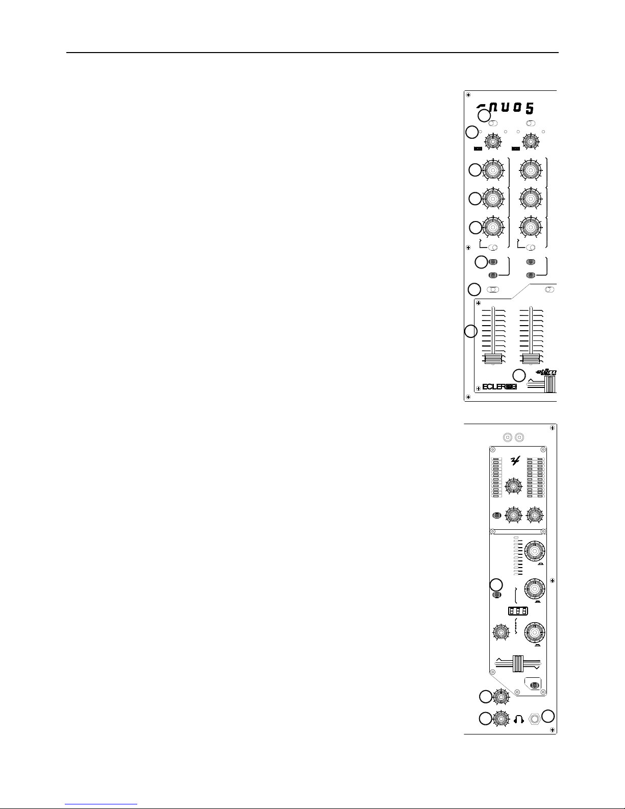
5.2 Control Description
5.2.1 Input selector
Each channel features an input toggle switch selector (1).
5.2.2 Channel GAIN
All the NUO5 input channels have an accessible input sensitivity GAIN control (4). The GAIN controls adjust the
input level of each channel in order to compensate the different sources connected to the mixer. All input sensitivity
adjustments must be done very carefully using the Input SP (Signal Present) (3) and PEAK leds (2), the VUMETER, and/or headphones as a reference. The standard level reference used to mix audio signals is 0dBV. To
optimize your mix, adjust your input the closest to 0dBV on the PFL Vu-meter and never reach the “clipping” level
using the red “warning” PEAK led as a reference for each channel.
5.2.3 Equalization
The rotary tone controls for each channels provide a +10/-30dB boost/cut at high (5) and low frequencies (7) and
+10/-25dB at the mid range (6). This great attenuation range is specially designed for creative live performance.
Also the bass frequencies can be “killed on the fly“ activating the BASS OFF switch (8) located below each BASS
rotary knob (except MICRO channel).
ATTENTION: Use equalization carefully, by boosting too much the low frequency range, you can induce an
excessive displacement of the speakers membrane.
5.2.4 Monitoring System
The NUO5 is equipped with a flexible and easy monitoring system that will allow the performers to finely tune
PFL/FX Cue (Pre-fader listening and Effect monitoring) and MIX (MIX Program Monitor) levels of the main inputs
through the VU-METER and the HEADPHONES.
Each channel as well as the effect processing can be monitorized visually and pre-listened pressing the dedicated
PFL (9) and/or FX CUE (30) yellow led button.
For HEADPHONES monitoring, the PFL/MIX rotary potentiometer (19) allows you to blend a selected PFL together
and/or FX CUE with the main MIX Program. The VOL rotary potentiometer (20) controls the level of headphones
output.
The NUO5 can display (38) at the same time PFL R+L signal (on the first left VU-METER bar) together with the
OUT 1 Right and Left signals ( second and third VU-METER bars).

11
5.2.5 Channel send to Effect
Pressing the FX SEND blue led button (10) send the channel signal both to the internal effect processor as well as
the EXTERNAL FX loop (45/46).
For the use of internal effect processing and EXTERNAL FX loop, please read the chapter 6. EFFECT
PERFORMANCE.
5.2.6 Channel Faders
The NUO5 uses a new generation of 60mm ECLER faders (13) featuring an improved precision and very smooth
movement, a very fast cut-in-time, and extra long life performance tested up to 4.000.000 operations when
combined to the ECLER VCA system (VCA=Voltage Controlled Amplifier).
Thanks to the VCA concept, it is possible to modify the gain/attenuation behaviour of faders. The NUO5 provides
this “Curve Adjustment” (12) feature (SOFT & SHARP position selector), enabling you to control the fade-in and
fade-out characteristics of all channel faders. Such fader curve adjustment is pretty unusual for a five channel mixer
and will bring new creative “cut” techniques to club mixing.
Channels 1, 4 and 5 can be routed to the NUO5 crossfader using the Assignation selector toggle switch (11/26).
“XFA” position routes the channel to the A side of the crossfader, and “MIX” position means the channel will not be
affected by the crossfader (assigned to the main MIX always).
5.2.7 ETERNAL Crossfader
The ECLER ETERNAL Crossfader (14) is an inductive fade technology based on a magnetic control. An extremely
light aluminium screen (0,5 gr.) cuts the flux lines of a magnetic field created between two sets of coils. This
electromagnetic modulation controls an assigned Voltage Controlled Amplifier that modifies the gain/attenuation of
the signal. The contactless technology is combined with a custom high quality glides mechanism to offer a very
smooth touch and succeed the most accurate Crossfader system !
The ETERNAL concept does have obvious advantages upon other existing systems using optical technology.
Unlike optoelectronic elements, the inductive concept is resistant to smoke, moisture, temperature and aging.
The ETERNAL Crossfader also features new “Tuning” features that will give the NUO5 the most accurate
Crossfader adjustment:
- CROSSMODE selector (16): depending of how sharp you want to get your “scratches”, the NUO5 allows you to
set-up the crossfader performance in FADE or SWITCH. The FADE Mode will give the crossfader a progressive
“roll-off” curve meanwhile the SWITCH Mode will “square” the crossfader curve in order to perform almost as a
Switch for fast “scratches”. Both curve modes are finely tuned by the SHAPE Adjustment potentiometer.
- SHAPE Adjustment (17): a knob SHAPE at the housing front let you adjust the crossfader slope from soft to hard.
- REVERSE Switch (15): so-called “Hamster Switch”, which reverses the crossfader normal direction. Depending
on the chosen "fader direction", you can perform “cuts” and “transforms” by moving the Crossfader in the same
direction.
- Electronic CUT-IN-TIME correction (18): a small rotary potentiometer of the housing front plate will allows you to
finely adjust the crossfader “Cut-in-time”. The “Cut-in-time” is the distance between the extreme end of the
crossfader and the very first “fade-in” point. The shortest position will give you almost an instant “Cut-in-time”; to
find the shortest “Cut-in-time”, the crossfader must be locked on the very end of the potentiometer in fade-out
position (the PGM is fully attenuated) and the CUT-IN-TIME knob must be turned to the right until (just before) you
get the sound. To lengthen the crossfader “Cut-in-time”, turn the knob to the left.
The crossfade function can be bypassed adjusting the CUT-IN-TIME knob at maximum (the cut point disappears).

12
The ETERNAL inductive crossfader has been designed mainly to perform extreme “turntablism” techniques, where
potentiometer movement has to be extremely smooth and fast.
In case the user prefers a more standard type of crossfader, the NUO5 comes with a separate long life VCA
crossfader. To exchange the crossfader, remove the fader area front plate, unplug the ETERNAL crossfader and
replace it with the separate long life VCA crossfader. Both potentiometers use the same plug configuration and the
ETERNAL REVERSE (15) and SHAPE (16/17) controls. The CUT-IN-TIME knob is not adjustable anymore (Fixed
cut-in-time) and the XF OFF (18) position is disabled with the long life VCA crossfader. We recommend to place the
CUT-IN-TIME knob at its maximum position (turned right) while using the long life VCA crossfader.
5.2.8 Internal effect controls
Please refer to next chapter 6 EFFECT PERFORMANCE.
5.2.9. TALKOVER function
The Microphone channel 5 features a TALKOVER Function. The red led push button activates (switch ON) the
TALKOVER and the PGM signal will be attenuated –30dB by the Microphone input (the Talkover time is set-up at 1
seconds). TALKOVER disables the channel 5 FX SEND function.
5.2.10 MASTER Levels
The NUO5 features two main output level controls MASTER 1 (35) and MASTER 2 (36). The OUT 1 (48/49) level is
controlled by the MASTER 1 level knob and is monitorized with the central and right Vu-meter bars (38). The
OUT 2 (50) level is controlled by the MASTER 2 level knob.
MASTER 1 and MASTER 2 are affected by R+L button. MASTER 1 is affected by the BAL balance control knob.
13
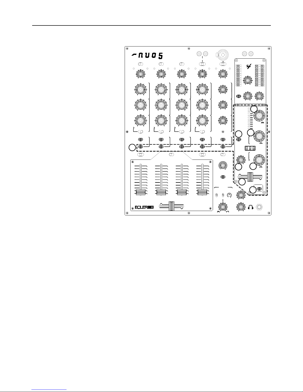
6. EFFECT PERFORMANCE
6.1 Mixer effect controls
FX SEND selector (10)
A very flexible multi-channel assignment
system allows the user to process various
input channels at the same time. The FX
SEND button assign the channel to the
internal effect processor and EXTERNAL
FX loop.
The FX SEND signal is Pre-fader by
default. If FX LAUNCH button is ON and
EFFECT selector is activated, the FX
SEND signal gets Post-fader.
For EXTERNAL FX processing, the
NUO5 has an external loop RCA
connection SEND (45) and RECEIVE
(46). Like the internal effect processing,
each channel can be assigned to the
EXTERNAL FX loop pressing the FX
SEND button. The FX SEND signal is
pre-fader by default, but is automatically
changed to post- fader if the 3 buttons FX
SEND (10), EFFECT (Encoder 33) and
FX LAUNCH (23) are activated. To use
the EXTERNAL FX “post-fader”, without
processing the internal NUO5 effects,
activate the 3 buttons FX SEND, EFFECT
(Encoder) and FX LAUNCH, and place
the WET-DRY crossfader (25) on “DRY”.
The FX SEND push button also controls the MIDI START/STOP functions. Please refer to chapter 8. MIDI USAGE.
Rotary/Push control EFFECT (33)
Choose the effect with the rotary control, and push the knob to activate/deactivate it. The NUO5 mixer offers 8
digital beat synchronized effects, 2 manual filters and 2 specific voice effects.
When the effect is activated, the led is blinking ; if the effect is only prepared and not activated then the led is stop
blinking (fix led). To send the activated effect in the mixer outputs, both the EFFECT control and FX LAUNCH
button (23) must be activated.
Each time you activate the LFO, Flanger, Phaser and Echo Flanger, the oscillation wave is reinitialised.
You can prepare a second effect (fix led) while one effect is activated (blinking led) ; push one time the EFFECT
control to simultaneously activate the second effect and deactivate the first one.
D
Y
R
10
Pitch Shifter
FX CUE
FX INPUT
Flanger Echo
Echo Reverb
Filtered Echo
High Pass Filter
Phaser
Vocoder
Flanger
Reverb
Delay
Low Pass Filter
L.F.O. Filter
W
FX LAUNCH
T
E
TAP
SELECT
REF.
PARAMETER
TIME
EFFECT
+2
-10
-38
-30
-20
-7
-4
-2
0
+4
+7
+10
+2
-38
-30
-20
-10
-7
-4
-2
0
+4
+7
+10
FX SEND FX SEND FX SEND
0
FX SEND FX SEND
10
33
31
30
27
28
25
23

14
Selector push button FX CUE (30)
Push the FX CUE selector to monitorize the effect.
The CUE signal is affected by DRY-WET crossfader (25).
The effect processor is continuously working for the cueing: the EFFECT activation does not affect the FX CUE.
In order to properly “CUE” the effect processor, the FX SEND (10) signal is Pre-fader by default. Once monitorized
and adjusted the effect parameters, keep the EFFECT selector activated and switch ON the FX LAUNCH (23)
button: the effect processing will automatically change to Post-fader, which means the effect mix is controlled by
the channel fader.
Rotary/Push control TIME (31)
Control the effect beat synchronization.
The value shown on the led display is a “Beat” fraction: “1.50” means “1 beat and a half” time value.
Low Pass Filter, High Pass Filter and Pitch Shifter are “manual” effects and are not affected by the TIME control.
Under Vocoder effect, TIME controls the carrier synthesis note.
Ex. with Delay effect: if the led display shows a “2.00” value, it means the processed signal is delayed 2 beats from
original input signal. “1-2” means ½ beat.
Oscillated effects L.F.O. Filter, Flanger and Phaser are synchronized in beat-patterns where 1x beat-pattern
= 1x beat.
The push function of the control TIME recalls TIME “Synchronization References”. You have 4 references (4
pushes) per effect.
Ex. with Delay effect :
1st push automatically sets a REF. Delay Time of “1-4” (1/4 beat Delay)
2nd push automatically sets a REF. Delay Time of “1-2” (1/2 beat Delay)
3rd push automatically sets a REF. Delay Time of “3-4” (3/4 beat Delay)
4th push automatically sets a REF. Delay Time of “1.00” (1 beat Delay)
5th push comes back to 1st REF. value.
Rotary/Push control PARAMETER (27)
Control one main parameter of the selected effect. The rotary control adjusts a different parameter type for each
effect: please refer to the effect description.
The push function of the control PARAMETER is a “TAP function”. The “TAP function” allows to enter manually a
beat sequence in the synchronization system. You have to push 3 times to enter a beat sequence, then the system
will briefly display the Beat Per Minute value calculated from the push sequence (around 3 seconds).
Effect mix crossfader DRY-WET (25)
The DRY-WET crossfader allows you to blend the processed signal (called WET) with the original input signal
(called DRY).

15
FX INPUT level control (28)
This potentiometer adjust the level of the effect processor input signal (sum of FX SEND signals).
This allows you to intensify or attenuate the effect without changing the DRY-WET mix.
Example 1 : Activate the Filtered Delay (adjust the TIME on “1-2” = ½ beat Delay) and raise progressively the FX Input level control: you will
progressively intensify the filtered Delay sound without affecting the WET-DRY mix balance.
Example 2 : Use a Delay with a lot of Feedback, if you completely turn left the FX Input you will attenuate the original input and leave only the
residual feedback.
Push button FX LAUNCH (23)
The FX LAUNCH button sends the signal after DRY-WET Crossfader to the main PGM output program.
When FX LAUNCH is OFF, the effect processor is bypassed and the selected channel (FX SEND) is processed
pre-fader in order you monitorize the effect adjustment: you can now adjust all the effect controls in the
headphones without affecting the main MIX.
If you FX LAUNCH ON, the effect mix is routed to the main PGM and the selected channel (FX SEND) is
processed now in post-fader which means the effect mix depends on the state of the FX SEND selected channel
fader.
In order to manage the multi-channel processing (various channels are sent to effect at the same time), the effect
processor output is controlled by the general channel fader VCA system (Voltage Controlled Amplifier). This means
that if one of the channel assigned to the effect processor (FX SEND) is open (fader up), the effect processor
output is open to the Master output (PGM).
This VCA system allows you for example to use a channel with no input signal as an “effect output fader” (WET
signal): choose the channel 5 for example with no input signal, assign it to the effect processor (FX SEND), and
use the VOL knob to control the effect processor output. If you keep the channel 5 VOL up, you can play a Delay
effect on any channel assigned to the effect processor (FX SEND) and use the proper channel fader as a “Send to
effect” fader: if you close it, you will hear only the Delay feedback with no original signal.
16
6.2 Effect description
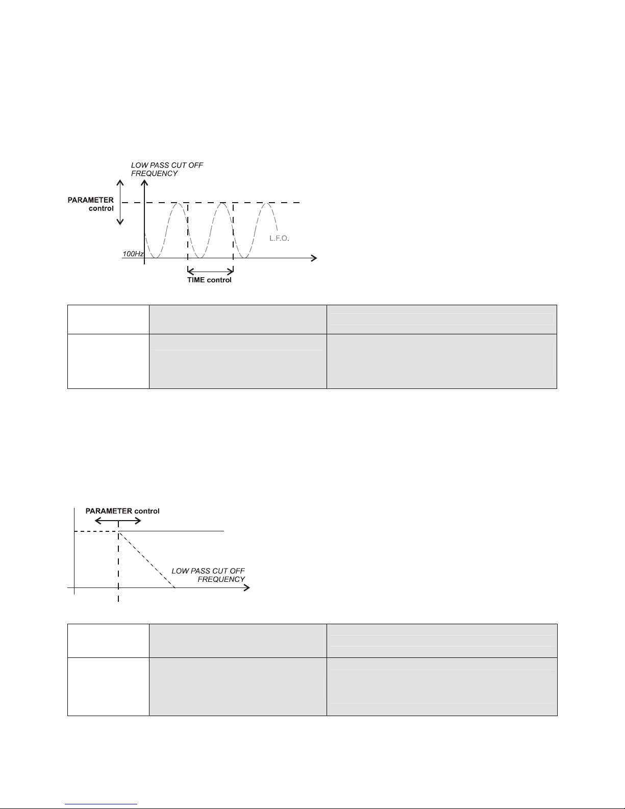
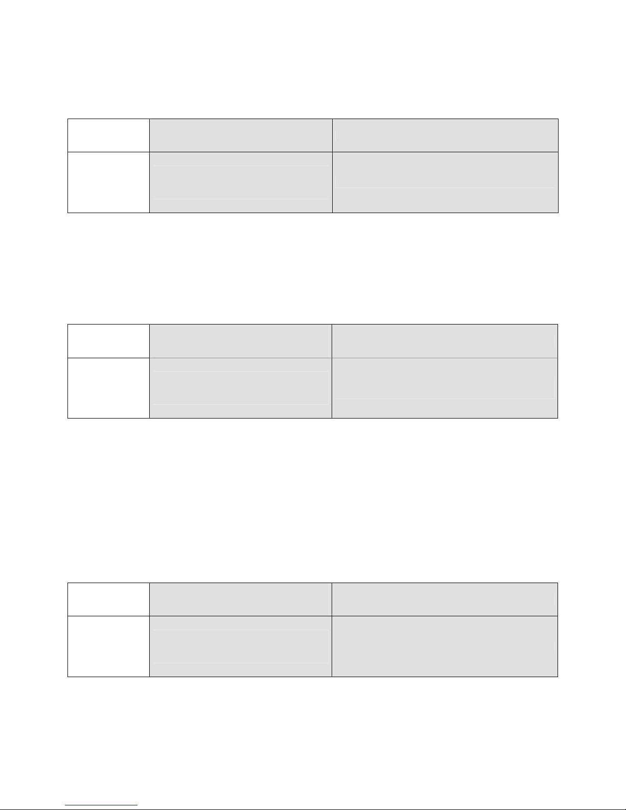
L.F.O Filter
A low pass filter is moved “in-beat” by an oscillator to create a synchronized “sound wave” effect.
If you slowly turn right the PARAMETER control (from “000” to “100”), you will boost the oscillation increasing the
maximum frequency cut-off: the music signal will start oscillating “in-beat” in the low frequencies and then oscillate
more and more in higher frequencies.
TIME
PARAMETER
L.F.O Filter
Oscillation cycle length
from 0.5 to 8 beat-pattern*
Oscillation cycle amplitude
Maximum oscillation cut-off
frequency from 100 (0%) to 12kHz (100%)
* 1 beat-pattern = 4 beats
Low Pass Filter
A filter that attenuates high frequency components of a signal. “Manual” Low Pass Filter should be manipulated
with a 100% WET MIX: placing the mixer WET/DRY crossfader (25) on “WET”.
You can manually move the filter “cut-off” frequency and mix for example a new track “opening” the filter
(PARAMETER “000”->”100”) which will “fade-in” the sound from bass to high frequencies!
TIME
PARAMETER
Low Pass Filter
---
(Manual)
Low Pass filter cut-off
frequency from
20kHz (0%) to “bypass” (100%)
17
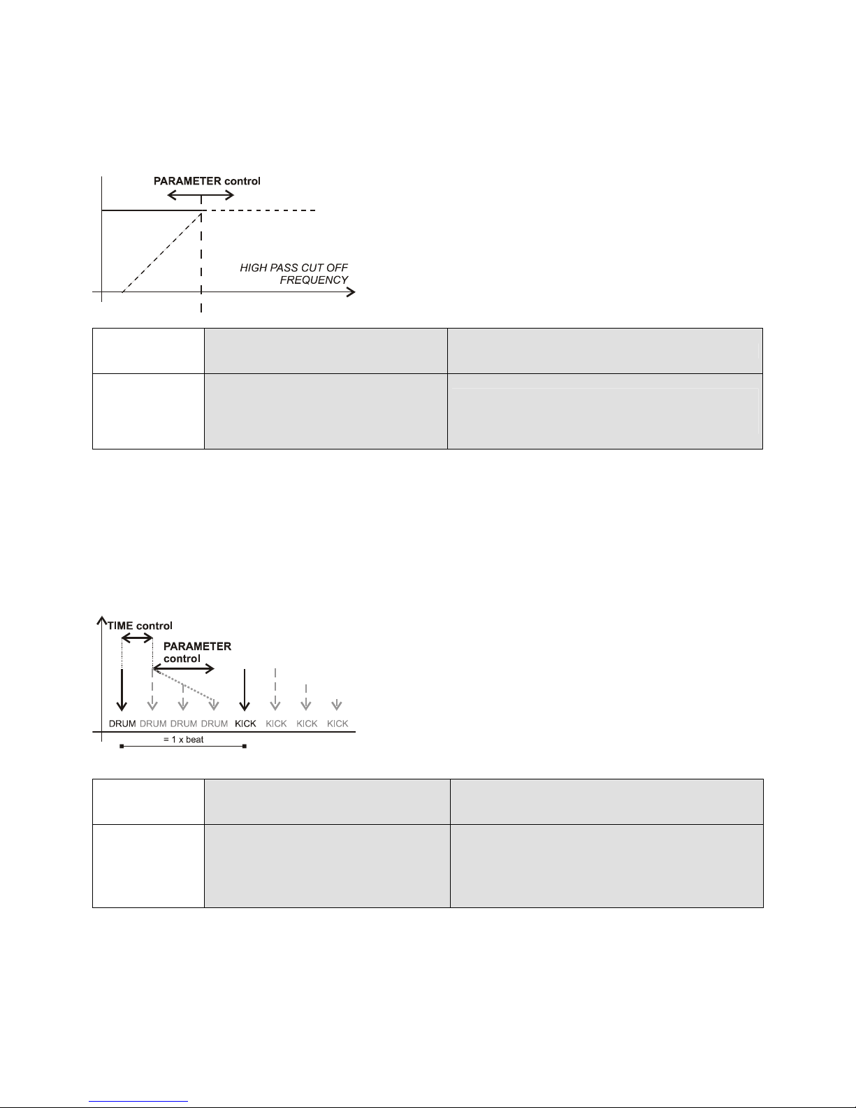
High Pass Filter
A filter that attenuates low frequency components of a signal. “Manual” High Pass Filter should be manipulated with
a 100% WET MIX: placing the mixer WET/DRY crossfader (25) on “WET”.
The user can manually move the filter “cut-off” frequency and mix for example a new track “opening” the filter
(PARAMETER “000”->”100”) which will “fade-in” the sound from high to bass frequencies!
TIME
PARAMETER
High Pass Filter
---
(Manual)
High Pass filter cut-off
frequency from
“bypass” (0%) to 20 kHz (100%)
Delay
Delays “in-beat” one or more of the output signals by a controllable amount called «Feedback». You can mix the
delay sounds in synchronization with the beat. The amount of delay feedback will increase sound reflections and
transform your Delay (one sound repeated) into Echo (multiple sounds repeated).
You can “Beat Transform” your mix adjusting the Delay Time: for example if you mix the original sound and the
delayed sound with a 1-2 (1/2 beat ) Delay Time, and you will “double” the music rhythm.
TIME
PARAMETER
Delay
Delay Time
from ¼ to 4 beats
Feedback %
18
Reverb
The effect recreates the sound waves decaying in an acoustic space due to bouncing off on walls, ceilings, objects
etc … The user can adjust the “Environment dimension” acoustics as well as the “Reverb” time (Decay Time, the
time it takes for the reverb to die off).
TIME
PARAMETER
Reverb
Environment Dimension
Room Size
from “Small Room” to “Church”
Decay Time
Flanger
This effect is a variable flanged delay linked to a Beat Per Minute controlled sinewave low frequency oscillation
(L.F.O.). This produces a dynamic swirling sound effect.
Long Flanger over 4 beat-patterns (= over 16 beats) will create a very smooth “space” ambiance to your mix.
TIME
PARAMETER
Flanger
Flange Speed
L.F.O. cycle length
from 0.5 to 8 beat-pattern*
Short Delay adjustment
Minimum Delay from 0.1ms (0%) to 6ms (100%)
* 1 beat-pattern = 4 beats
Phaser
A Phaser effect is a time-varying all pass filter that works by shifting portions of the audio signal out of phase
(±180º), and then adding the processed signal back to the original one. These frequencies are shifted following a
Beat Per Minute controlled low frequency oscillation (L.F.O.) which creates a sweeping phaser sound. The
feedback adjustment raises the filter gain just below each notch in the frequency range, creating a more
pronounced effect.
Long Phaser over 4 beat-patterns (= over 16 beats) will create a very smooth “space” ambiance to your mix. For
"singing" phaser sounds, raise the feedback adjustment.
TIME
PARAMETER
Phaser
Phasing Speed
L.F.O. cycle length
from 0.5 to 8 beat-pattern*
Phaser Feedback %
* 1 beat-pattern = 4 beats
19
Vocoder
The vocoder can be used to disguise your voice and make your voice sound "robot-like". The Vocoder works by
splitting the input signal (Modulator, ideally a voice) into 8 bands, finding the magnitude of each band, and then
amplifying the corresponding bands of a synthesis signal (Carrier) by that magnitude.
The NUO5 vocoder offers 15 types of carriers and 25 different synthesis notes.
TIME
PARAMETER
Vocoder
Carrier Synthesis Note
from 1 to 25
Carrier Timbre
from 0 to 15
Pitch Shifter
This effect allows you to “shift” the Pitch of an input signal without changing its sound duration. Typically used to
change the “gender” of the sound.
The NUO5 Pitch Shifter allows you to shift ±12 half tones in 100 steps.
TIME
PARAMETER
Pitch Shifter ---
Pitch Tones
±12 half tones in 100 steps
Echo Reverb
This effect combines a Beat Per Minute synchronized Echo with adjustable feedback and a Reverb: the input signal
is delayed and send to a «medium-room» Reverb.
TIME
PARAMETER
Echo Reverb
Delay Time
from ¼ to 4 beats
Delay Feedback (Echo)
20
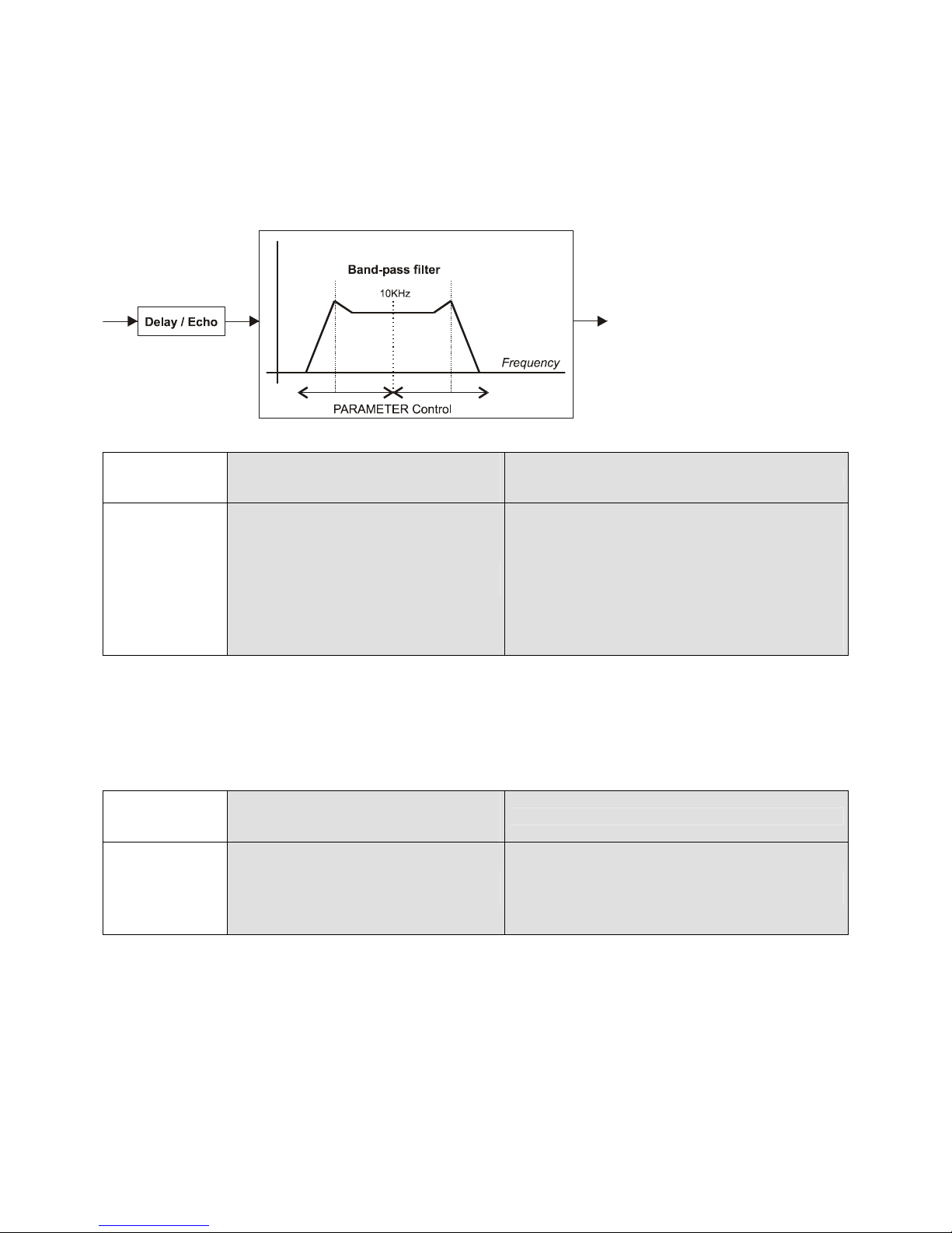
Filtered Echo
This effect combines a Beat Per Minute synchronized Delay with fixed feedback (Echo) and a variable Band-Pass
Filter: the input signal is delayed and send to a 1KHz Band-Pass Filter. The width of the 1KHz Band Pass is
adjustable moving its Low-Pass and High-Pass cut-off frequencies.
For “Techno” mixing, the Filtered Echo is particularly efficient as it can “accelerate” the rhythm of certain high
frequencies: adjust the TIME control on “1-2” (1/2 beat delay), the WET/DRY crossfader in the middle, and slowly
move the PARAMETER control from “100” to “070”.
TIME
PARAMETER
Filtered Echo
Delay Time
from ¼ to 4 beats
Band Pass filter cut-off
HP Frequencies
from 100Hz (0%) to 1KHz (100%)
LP Frequencies
from 1KHz (100%) to 20KHz (0%)
Flanger Echo
This effect combines a Beat Per Minute synchronized Echo with fixed feedback and a Flanger: the input signal is
delayed and send to a variable flanged delay (L.F.O. modulated).
TIME
PARAMETER
Flanger Echo
Delay Time
from ¼ to 4 beats
Short Delay adjustment
Minimum Delay from 0.1ms (0%) to 6ms (100%)
Check out the www.eclerdjdivision.com for further effect performance “tips and tricks”.

21
7. PC MODE – EFFECT REMOTE PARAMETERING
The NUO5 is world’s first programmable effect dj mixer.
The NUO5 internal effects we previously described can be edited and reparametered on a PC program via
Universal Serial Bus: the edi:lab software.
The edi:lab software requires Windows 98SE, ME, 2000 or XP.
7.1 Drivers and Software installation
An installation CD-rom as well as a USB cable is provided with the NUO5 mixer.
Before installing the hardware drivers and edi:lab software:
Switch ON the NUO5 mixer.
Press the PARAMETER Control of the NUO5 for 5 seconds. The led display shows “PC”: you are in “PC Mode”.
Connect the USB cable between the NUO5 mixer and your PC (Computer USB Port).
Switch ON the computer.
Hardware driver installation
When you connect for the first time the USB cable coming from the NUO5 mixer to your PC, the computer will
detect a new hardware device and request its driver installation. The driver is simply a “software link” between the
computer Operation System, the application software (the edi:lab in our case) and the communication port device
of the hardware.
Install the USB drivers from the installation CD-Rom provided with the mixer.
Edi:lab software installation
Once you have installed the USB drivers on your PC you can start installing the edi:lab program running
“setup.exe” from the CD-ROM.
22
7.2 PC Mode operation and usage
You have installed NUO5 drivers and edi:lab software, you can now start designing
your own effect setup …
Every time you want to open the edi:lab software you have to set FIRST the NUO5
mixer in “PC Mode”. As previously explained, the NUO5 “PC-Mode” is set pushing
the PARAMETER control of the mixer during 5 seconds until you see “PC” on the
led display. Once the NUO5 mixer is in “PC MODE”, connect the mixer to the PC
using the USB cable, and then open the edi:lab software on your PC (Desk Icon).
The internal mixer effects can be reprogrammed in real-time with the edi:lab
software. The software remotely modificates the programs of the NUO5 processors so that the sound result can be
heard directly on the NUO5 mixer, as if the console were used normally. In “PC Mode” the EFFECT, TIME and
PARAMETER encoders of the mixer are disabled (controllable now through edi:lab software). In «PC Mode» the
NUO5 mixer can be used normally including the FX CUE function, FX INPUT level potentiometer and the
DRY-WET crossfader. This allows to open and close the edi:lab software while “live” performing the NUO5 mixer.
The edi:lab control window opens the effect selected on the NUO5 mixer just before going into “PC Mode” (L.F.O.
Filter by default).
If the edi:lab software is closed on the PC, the NUO5 mixer automatically passes from “PC Mode” to normal mode.
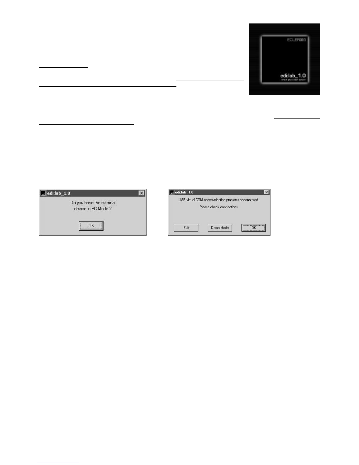
7.2.1 Software start up and communication check:
When you open the edi:lab software, a pop-up will always remind you to set the NUO5 mixer in “PC Mode”. To set
the mixer in “PC Mode”, press the TAP button (PARAMETER knob) for 5 seconds until the led display shows “PC”.
Only one NUO5 mixer can be connected at the same time to the edi:lab.
Under “PC Mode”, the digital effect selections and adjustments (TIME and PARAMETER knobs) are disabled on
the mixer and transferred to the computer control.
If you do not want to enter the edi:lab in “PC Mode”, you can select “Demo Mode” and open the software
“stand-alone”, without any communication with the mixer.
To exit the “PC Mode”, close the edi:lab software (Edition->Exit) from the computer. In case of computer problem,
you can exit the “PC Mode” pressing the mixer TAP button for 5 seconds. Leaving the “PC Mode” from the mixer
can create some unpredictable software behaviours certain Windows Operating Systems, this is why we
recommend to exit the “PC Mode” always from the software itself, exiting the edi:lab.
It is not recommended to unplug the USB while running the edi:lab.
NOTE: Only a mixer can be connected at same time.
23
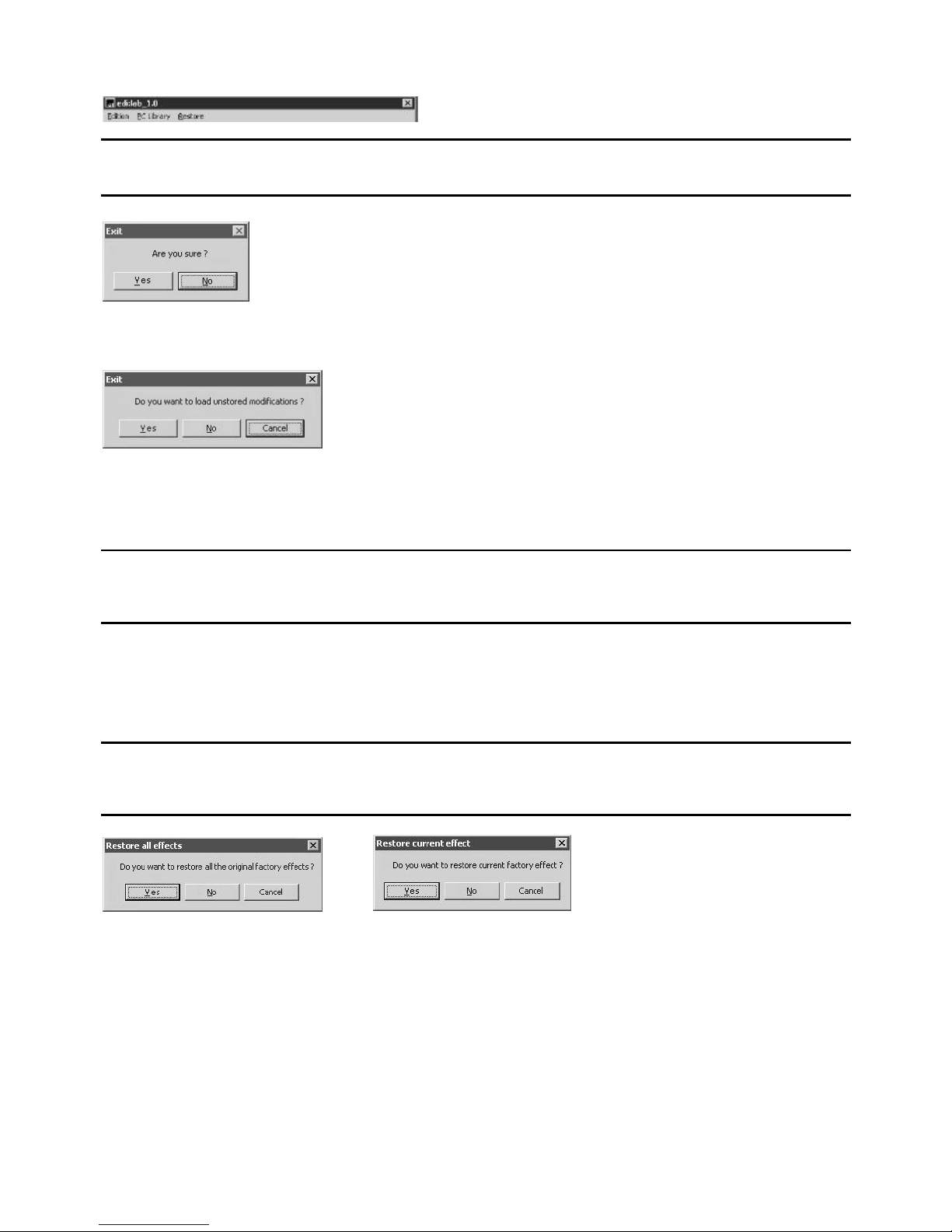
7.2.2 Scroll Menus:
Edition: Exit exit the edi.lab program
Yes closes the application
No aborts the “Exit” procedure and comes back to the application
Yes closes the application updating the NUO5 settings with all effect parameters not stored yet
No closes the application reloading the unsaved effect with the set-ups foregoing the editing
Cancel aborts the “Exit” procedure and comes back to the application
PC Library: Open open an effect set-up from your library
Save save an effect set-up in your library
Customized effect preset files can be exchanged and used under different edi:lab applications. For example you
can program your specific L.F.O. or Phaser and send it to an other NUO5 user that will be able to open it under his
own edi:lab application and load it on his own console.
Restore All effects Restore factory set-up for all effects
Current effect Restore factory set-up of current effect only
24
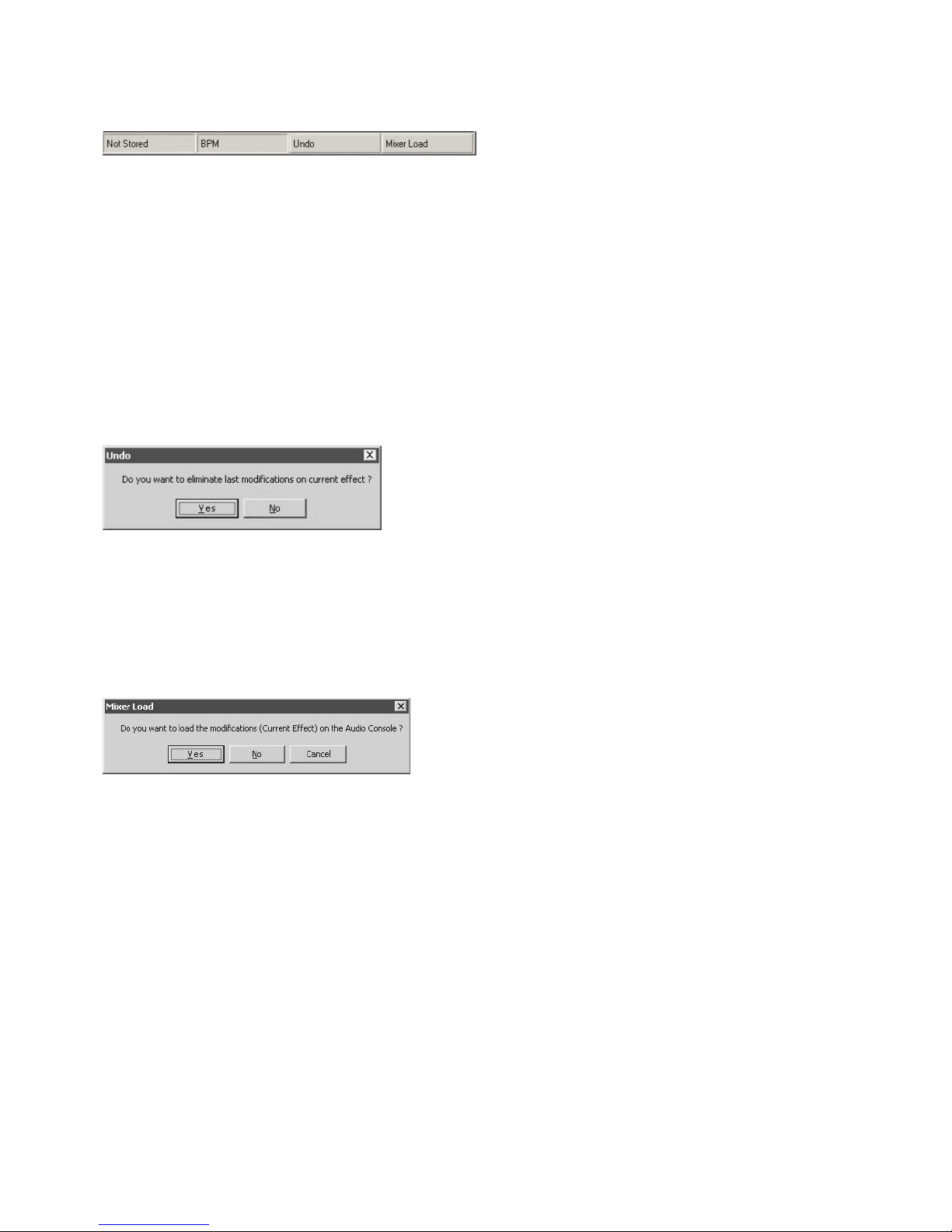
7.2.3 Status Bar
The status bar displays the current “system status”.
Stored / Unstored Status
This cell gives the storing status of the current effect parametering. “Not Stored” means the present effect set-up
displayed on the edi:lab window is not stored in the NUO5 mixer: if you leave the edi:lab application, the NUO5
will not keep this parameter set-up. “Stored” means the present effect set-up displayed on the edi:lab window as
already been loaded on the mixer: if you leave the edi:lab application, the NUO5 will keep this parameter set-up.
BPM Status
This cell gives the Beat Per Minute sequence value recognized by the system. The value by default is 120BPM.
Undo button
This button reloads the last effect configuration “Stored” by the system.
Yes eliminate the last modifications made on the current effect, and reloads the latest “Stored” configuration.
No aborts the “Undo” procedure.
Mixer Load button
This button loads the current effect set-up on the NUO5 mixer.
Yes loads the current effect configuration on the NUO5 mixer (except mixer controls TIME and PARAMETER).
The loaded effect configuration is now the mixer default set-up and will replace the original factory settings. To
come back to original factory effect settings, use the “Restore” scroll menu.
No/Cancel aborts the “Undo” procedure.
25
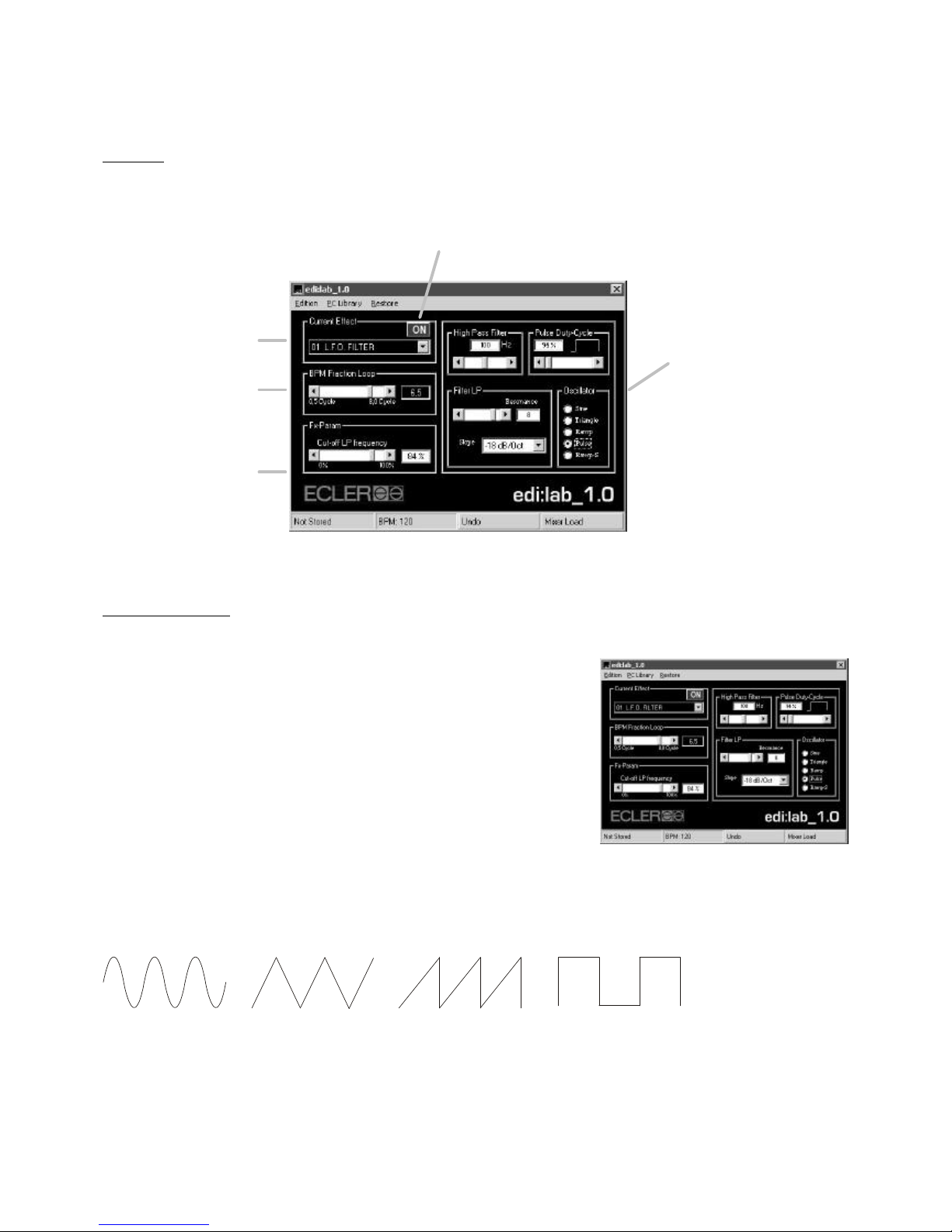
7.2.4 Effect Design:
Overview
Effect parametering
L.F.O. FILTER (01)
High Pass Filter:
You can finely adjust an input High Pass filter in order to avoid possible
“Bass” rumble effect when L.F.O. is played on large P.A. systems.
Oscillator:
The L.F. Oscillation can follow a different oscillator forms. Check the
different oscillators below.
Pulse Duty Cycle:
Adjusts the cycle sequence of the “pulse” oscillator.
Filter LP:
The oscillated Low Pass filter (L.F.O.) Slope (how “sharp” the filter) and Resonance (cut-off gain) can be finely
adjusted with the edi:lab software.
Sinewave oscillator Triangle oscillator Ramp oscillator Pulse oscillator
ON/OFF Button
Remotely controls the mixer
EFFECT encoder “push fu
nction”
(Activate/Deactivate)
Remotely controls the
mixer
EFFECT encoder
(Effect Selection)
Remotely controls
the mixer TIME
Encoder
Remotely controls the
mixer
PARAMETER
encoder
Extended effect
parametering:
these controls
reprogram the main
effect structure
components

26
LOW PASS FILTER (02)
High Pass Filter:
You can finely adjust an input High Pass filter in order to avoid possible
“Bass” rumble effect on large P.A. systems.
Filter LP:
The manual Low Pass filter Slope (how “sharp” the filter) and Resonance
(cut-off gain) can be finely adjusted with the edi:lab software.
HIGH PASS FILTER (03)
Low Pass Filter:
You can finely adjust an input Low Pass filter and then limit the High Pass
movement.
Filter HP:
The manual High Pass filter Slope (how “sharp” the filter) and Resonance
(cut-off gain) can be finely adjusted with the edi:lab software.
DELAY (04)
High Pass Filter:
You can finely adjust an input High Pass filter in order to avoid possible
“Bass Rumble” effect on large P.A. systems.
REVERB (05)
In HP Filter:
You can finely adjust an input High Pass filter and notch some low
frequencies out of the Reverb process. This low-frequency damping
(closing the filter) allows to simulate bass absorbing materials (like wooden
panels) in real rooms.
In LP Filter:
You can finely adjust an input Low Pass filter and notch some high
frequencies out of the Reverb process. This high-frequency damping
(closing the filter) allows to simulate high frequency absorbing materials in real rooms.
Out HP Filter:
You can finely adjust an output High Pass filter and eliminate some reverbed low frequencies. This low-frequency
damping (closing the filter) allows to simulate bass absorbing materials (like wooden panels) in real rooms.
Out LP Filter:
You can finely adjust an output Low Pass filter and eliminate some reverbed high frequencies. This high-frequency
damping (closing the filter) allows to simulate high frequency absorbing materials in real rooms.
Density:
Simulates the density of the reverberation room (objects, people etc …).
27
E.R.%:
Adjusts the Early Reflections, the time for the first reflected sounds to reach a listener's ears: the greater the
spacing of the early reflections, the bigger the virtual room sounds.
F.R.%:
The time between the reception of the direct signal by the listener and start of the Reverb portion of the effect is
called Predelay. The F.R.% control adjusts the fast reflection pre-delay generator: the faster is the pre-delay
reflection, the smaller sounds the room.
Phase:
The Phase switch reverses the phase of the reverb signal output and adds a bright sparkle to the overall sound.
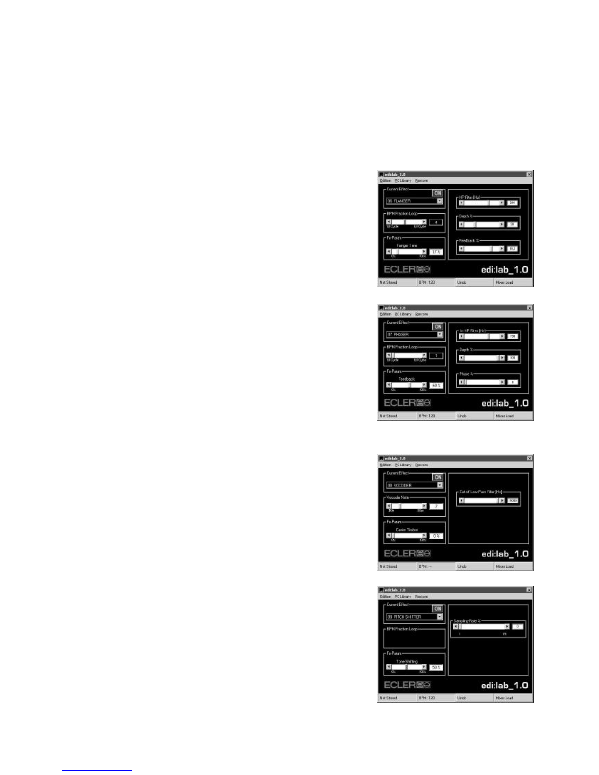
FLANGER (06)
HP Filter:
You can finely adjust an input High Pass filter in order to avoid possible
“Bass Rumble” effect on large P.A. systems.
Depth %:
Controls the “sweep'' or maximum delay swing of the variable short delay
(Flanger).
Feedback %:
Controls the flanged delay feedback %.
PHASER (07)
In HP Filter:
You can finely adjust an input High Pass filter in order to avoid possible
“Bass Rumble” effect on large P.A. systems.
Depth %:
The phaser effect shifts the audio signal out of phase following an
oscillation movement. The Depth % adjusts the depth of this oscillation
(L.F.O.).
Phase %:
This control adjusts the rate of phase variation (100%= phase variation of
±180º).
VOCODER (08)
Cut-off Low Pass Filter:
Adjusts the carrier input Low Pass filter cut-off frequency.
PITCH SHIFTER (09)
Sampling Rate %:
You can lower the Picth Shifter sampling ratio and transform the input
signal into a distorted “lo-fi” signal.
28
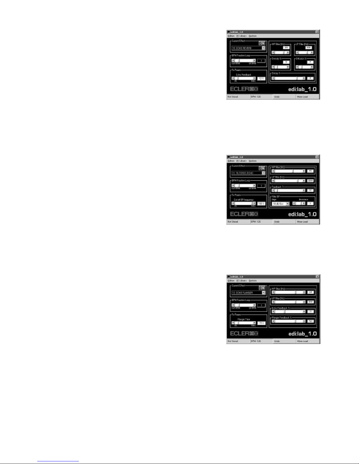
ECHO REVERB (10)
HP Filter:
Controls the High Pass filter placed in the Echo Feedback. This feedback
High Pass filter allows you for example to avoid possible “Bass” rumble
effect when played on large P.A. systems.
LP Filter:
Controls the Low Pass filter placed in the Echo Feedback.
Diffusion:
This control simulates the “diffusion” of the reverberated sounds: a small
diffusion will recreate a room where the walls are very flat (sounds are bounced straight, not diffused).
Density:
Simulates the density of the reverberation room (objects, people etc …).
Decay:
Decay adjusts the “Reverb Time”, the time it takes for the reverb to die off.
FILTERED ECHO (11)
HP Filter:
Controls the High Pass filter placed in the Echo Feedback. This feedback
High Pass filter allows you for example to avoid possible “Bass” rumble
effect when played on large P.A. systems.
LP Filter:
Controls the Low Pass filter placed in the Echo Feedback.
Feedback:
Gives more or less feedback to your Echo. The amount of feedback will increase delayed reflections.
Filter BP:
You can modificate the Band Pass filter aspect adjusting the Slope (how “sharp” the filter) and Resonance (cut-off
gain) specifications.
ECHO FLANGER (12)
HP Filter:
Controls the effect output High Pass. This High Pass filter allows you for
example to avoid possible “Bass” rumble effect when played on large P.A.
systems.
LP Filter:
Controls the effect output Low Pass.
Echo Feedback:
Gives more or less feedback to your Echo. The amount of feedback will
increase delayed reflections.
Flanger feedback:
Controls the flanged delay feedback %.

29
8. MIDI USAGE
The DIN 5 (180º) MIDI OUT connector allows you to control external devices using MIDI protocol.
MIDI (Musical Instrument Digital Interface) is a standard protocol for communication between electronic musical
instruments and computers. MIDI devices can work as Slave (controlled) or Master (controls) units. The NUO5
works as a Master MIDI unit which means it can control other electronic musical instruments (Synthetisers,
Sequencers, Drum Machines etc ... even Light Controllers).
The MIDI functions of the NUO5 are “System Messages” with no specific MIDI channel assigned.
Via its MIDI OUT, the NUO5 sends a continuous synchronization code called MIDI Clock which can synchronize
the external(s) MIDI device(s). The NUO5 MIDI Clock signal follows the BPM value (Beat Per Minute) calculated by
the internal BPM Processor. To control the external(s) MIDI device(s), remember to set it first as a “Slave” unit
(External Clock set-up).
The NUO5 can also send MIDI START and MIDI STOP orders to external(s) MIDI device(s) which allows you to
“launch” and “stop” sequences of external(s) MIDI device(s). The MIDI START and MIDI STOP orders are
controlled by the EFFECT Knob (Push): each time you push the EFFECT Knob, the MIDI OUT sends a MIDI
START (“Activate SELECT”) or “MIDI STOP” (“Deactivate SELECT”).
The MIDI Functions are disabled when the NUO5 gets under “PC MODE“.
9. FURTHER CONSIDERATIONS
9.1. Ground loops
Ensure at all times that no signal sources reaching the mixing desk and no devices connected to its output have
their earths interconnected; that is, earth should never reach them via two or more different paths, as this could
lead to humming which could even interfere with sound reproduction quality. In order to avoid earth loops, ensure
that the shielding of cables, if connected to the chassis, are never connected with each other.
9.2. Audio connections
As a general rule of thumb, make the signal connections as short as possible and use the best connectors and
cable available. Cables and connectors are frequently held cheap, forgetting that a bad connection can result in a
poor sound quality.
9.3. Background noise
The use of active circuitry can yield, depending on the configuration, to a significant noise level. The NUO5 has
been designed for the minimum possible noise. Anyway, the noise level will always depend on the correct use and
installation of the mixer. It is not the same setting up the FADER at "2" and the MASTER at "10" that the other way
round; FADER at "10" and MASTER at "2". In the first case you get a poor signal to noise ratio that will be fully
amplified by the master while on the second we have a good signal to noise ratio only amplified by "2". As a result,
the background noise is greater in the first case than in the second one.
9.4. Cleaning
The front panel should not be cleaned with dissolvent or abrasive substances because silk-printing could be
damaged. To clean it, use a soft cloth slightly wet with water and neutral liquid soap; dry it with a clean cloth. Be
careful that water never gets into the unit through the holes of the front panel.

30
10. FUNCTION LIST
1. Input selector
2. Peak level indicator (+10dB), PEAK
3. Signal Present indicator (-40dB), SP
4. Input sensitivity adjust, GAIN
5. Treble frequency control, TREBLE
6. Midrange frequency control, MID
7. Bass frequency control, BASS
8. Bass frequency isolation switch, BASS OFF
9. Prefader listening control, PFL
10. Send switch to effect bus, FX SEND
11. Send to XF switch, XFA/MIX/XFB
12. Fader curve selector, FADE CURVE
13. VCA Fader
14. ETERNAL Inductive Crossfader
15. Crossfader reverse function
16. Crossfader curve mode Switch/Fade
17. Crossfader Shape adjuster
18. Crossfader “Cut-in time” adjustment, CUT IN
19. PFL/MIX monitoring crossfade
20. Headphones volume control, VOL
21. Headphones stereo jack connector
22. Talkover button switch, TALKOVER ON
23. Effect launch to PGM button, FX LAUNCH
24. Channel 5 volume control, VOL
25. Effect mix crossfader, WET-DRY
26. Send to XF switch, MIX/XFB
27. Parameter data rotary control and manual tempo push function, PARAMETER
28. Effect input level attenuator, FX INPUT
29. 7 segment led display for TIME and PARAMETER
30. Effect monitoring selector, FX CUE
31. Effect beat synchronization rotary control and beat value references (4 ref. per effect) push function, TIME
32. Effect led indications
33. Effect selection rotary control and activation push function, EFFECT
34. MASTER 1/2 Left and Right signal sum, L+R
35. Output 1 level control, MASTER 1
36. Output 2 level control, MASTER 2
37. Output 1 Balance, BAL
38. PFL and Master vu-meter, PFL / MASTER
39. Top Recording RCA connector, REC2
40. Microphone XLR/JACK combo connector, MIC
41. Top Low Line RCA input, L-LINE
42. Turntable phono RCA inputs, PHONO
43. High Line RCA inputs, H-LINE
44. Low Line RCA inputs, L-LINE
45. External effect SEND output, SEND
46. External effect RETURN input, RETURN
47. Recording RCA connector, REC1
48. Left channel balanced output, OUT1 L
49. Right channel balanced output, OUT1 R
50. RCA output, OUT2
51. USB Port
52. Mains socket
53. Fuse holder
54. Mains OFF/ON Switcher, O/I
55. MIDI Output, MIDI OUT
56. Ground pin, GND
 Loading...