

Page 1
USER MANUAL
MANUAL DE INSTRUCCIONES
MANUEL UTILISATEUR
BEDIENUNGSANLEITUNG
Page 2

2
Page 3

User Manual Contents
1. IMPORTANT REMARK 04
1.1. Safety Instructions 04
1.2. Warranty Descriptions 04
2. INTRODUCTION 05
3. INSTALLATION 05
3.1. Audio inputs connections 06
3.2. Audio outputs connections 07
4. QUICK START 08
5. OPERATION AND USAGE MANUAL 09
5.1. Start-up 09
5.2. Control Description 09
6. MIDI CONTROLS 12
7. MIDI CONTROL OPERATION 15
8. FURTHER CONSIDERATIONS 18
9. FUNCTION LIST 19
10. FUNCTION DIAGRAM 19
11. TECHNICAL CHARACTERISTICS 71
12. DIAGRAMS 72
12.1. Figures 72
12.1.1. Connection diagram 72
12.1.2. Rack ear system (Fig1) 73
12.1.3. Internal jumper configuration 74
13. BLOC DIAGRAM 75
All numbers subject to variation due to production tolerances. ECLER S.A. reserves the right to make changes or
improvements in manufacturing or design which may affect specifications.
3
Page 4
1. IMPORTANT REMARK
1.1. Safety Instructions
In order to get the optimum operation and efficiency from your mixing unit, it is VERY IMPORTANT - before you
plug anything - to read this manual very carefully and take seriously into account all considerations specified within
it. We strongly recommend that its maintenance be carried out by our Authorised Technical Services.
This apparatus must be earthed through its mains cable.
Do not expose the unit to rain or water splashes, and do not place liquid containers or incandescent
objects like candles on top of the unit. Do not obstruct the ventilation shafts with any kind of material.
Any change in the configuration of the unit must be carried out by a qualified technician. Should any
connection / disconnection task be done, always disconnect the unit from the mains supply.
1.2. Warranty Descriptions
Your ECLER equipment has undergone exhaustive laboratory and quality control tests before leaving the factory.
Nevertheless, your may be in need of our Technical Service during the period covered by the Guarantee or
afterwards. In that case, carefully protect your equipment in its original packet and send it to our Technical Service
with the transport and insurance paid. Attach a photocopy of your Guarantee Certificate and a detailed description
of the defect you have observed.
ECLER, S.A. guarantees its ECLER products against material or fabrication defects for a ONE-YEAR period (3
YEAR period in SCLAT and NUO series mixers and in the SPM technology amplifiers and 5 YEAR in the
ETERNAL potentiometers) after the date of original purchase.
ECLER, S.A., will repair the defective equipment within the aforementioned period, with no charge for parts and
labour.
To ensure the validity of the Guarantee, it is essential that the attached Guarantee, Registration Card is filled out
correctly and remitted to your ECLER distributor, within 10 DAYS after date of purchase.
The Guarantee is non-transferrable and protects the original buyer only.
The Guarantee does not cover:
- Damages caused by mistreatment or negligent handling, lack of elementary precautions, disregard to the
instructions in the manual, faulty connection or accidents.
- Sets that have been manipulated, altered or repaired other than at the authorized Technical Service centers.
- The exterior fittings and electro-mechanical parts, nor their wear due to use.
- Shipping and insurance expenses, nor for damages the set may incur during its transport.
ECLER, S.A., will not be held responsible for any direct or indirect damage, loss or other damage originated by or
relating to the set.
This Guaranteed is valid only for repairs or services carried out at an authorized Technical Service Center.
4
Page 5
2. INTRODUCTION
Congratulations! You are the owner of a genuine ECLER professional equipment. The NUO4 has been carefully
designed in collaboration with leading dj performers and advance music producers, developed with the highest
quality components, and manufactured in-house (Barcelona-Spain) under strict quality controls.
The NUO4 is a five-channel stereo mixer with capacity for 11 separate sound sources.
Due to its robustness and format, the NUO4 is mainly dedicated to professional mixing applications (club,
homestudio), or anywhere where a compact sized, high performance mixer is required.
3. INSTALLATION
The first thing to take into consideration when placing your NUO4 is your comfort and an easy access to all the
connections. The NUO4 is basically conceived as a tabletop mixer and its usual placement will be between two
vinyls or CD players. The mixer has a 14.57’’ (37cm) depth and 12.6’’ (32cm) width format. The optional metallic
side profiles kit allows you to firmly fix your mixer to the surface over which it is placed or over its own profiles
(Fig.1). These profiles also allow to tilt the mixer's position for an easier operation. There is another metal brackets
option ('NUORAKI') that allows the mixer mounting in a standard 19" rack.
Because of the high gain of the PHONO and MICROPHONE inputs, always try to place the mixer as far away as
possible from noise sources (dimmers, engines, etc.) and mains wires. For the very same reason, and under any
circumstance, you should never remove the unit's metallic cover.
The power consumption of the NUO4 is very low, so they do not need any cooling, but you should avoid extreme
temperatures and the atmosphere should be as dry and dust free as possible.
The NUO4 operates now with a new universal input power supply “Switching Power Supply” and can perfectly
works without any internal modification from 90V to 264V – 47 to 63Hz. Make sure that the mains-wire is far away
from the signal-cables in order to avoid any possible audio hum.
In order to protect the unit from an eventual electrical overload it carries a T 500mA fuse. Should it ever blow up,
unplug the unit from mains and replace it with an identical one. If the new fuse blows again contact immediately
with our authorized technical service.
ATTENTION: NEVER SHORT-CIRCUIT THE SECURITY PATH NOR USE A HIGHER VALUE FUSE.
CAUTION: Fuse substitutions have to be performed by a qualified technician.
5
Page 6

3.1. Audio inputs connections
Input 1 H-LINE CD player
Input 1 PHONO Turntable
Input 1 L-LINE Computers, Recorders...
Input 2 H-LINE CD player
Input 2 PHONO Turntable
Input 3 H-LINE CD player
Input 3 PHONO Turntable
Input 4 PHONO Turntable
Input 4 H-LINE CD player
Input 4 MIC Microphone
Input 5 (computer) AUDIO IN Sound card
PFL Monitoring
- Phono Inputs:
Phono Turntables must be fitted with a magnetic cartridge with nominal output level between -55dBV and -25dBV
(1,77 to 56mV). The PHONO inputs (42) of the NUO4 have a high headroom (margin before saturation) and it can
handle higher output cartridges than what is usual. These inputs are supplied with a nominal input sensitivity of
-40dBV (10mV). The NUO4 has two oversized ground terminals to connect the turntables ground wire.
- Line Inputs:
Given the important level differences between usual LINE and CD sources, the NUO4 provides specialized inputs
for each source. The sensitivity of the HIGH LINE (41) input is 0dBV (1V), while the LOW LINE (43) sensitivity is
-10dBV (316mV). CD Players, DAT, MP3, and DVD Audio should be connected to the HIGH LINE input. Tape
players, tuners and some production devices (samplers, sequencers) should be connected to the LOW LINE input.
- Microphone Inputs:
The MIC input (49) is ready for a nominal input level of -50dBV (3.16mV) and is equipped with a XLR3 connectors.
The MIC ATT switch on the rear panel (48) allows a 20dB attenuation on the input sensibility, so that it is changed
from –50 to –30dB (3.16 to 31.6 mV). The connection of balanced signals is as follows:
Hot or direct signal > Pin 2
Cold or inverted signal > Pin 3
Ground > Pin 1
Low impedance (200 to 600Ω) monophonic microphones must be used. In case of working with an unbalanced
connection Pin 1 and Pin 3 must be short-circuited. The NUO4 features a Phantom power supply for the
connection of condenser microphones. A set of internal jumpers allow you to inhibit the phantom power for the
microphone. The default setting of these jumpers on the NUO4 is "Phantom ON". See configuration diagram.
- Computer input
AUDIO IN: This input has a -10dB rated sensitivity, for a correct level matching with sound cards outputs, allowing
a gain adjustment between -∞ and 0dB.
PFL: It has a rated sensitivity of 0dB. This input is designed for prelistening with audio mixing software. It must be
connected to a second sound card's output.
6
Page 7

3.2. Audio outputs connections
Out 1 Main power amplifier
Out 2 Booth/Room2 power amplifier
Rec Recording
External FX External effect device
(Send and Return) (Input and Output)
Monitor Headphones
- Master Output 1:
These stereo outputs feed the main house P.A. system through a XLR3 Balanced connections. The OUT 1 (55-56)
level is set at 0dBV (1V) but can be changed to +6dBV (2V) through internal jumpers. OUT 1 is controlled by
MASTER 1 (24) level potentiometer.
- Master Output 2:
Commonly used as an independent local "Booth" output for the DJ. This stereo OUT 2 (54) has unbalanced RCA
connections and its level is set at 0dBV (1V) but can be changed to +6dBV (2V) through internal jumpers. The
OUT 2 level controlled by the MASTER 2 (25) potentiometer.
OUT 1 and OUT 2 additionally have a BAL balance control (27) and a common L+R mono/stereo switch (26) for
both outputs.
- Recording Output:
This output pair uses RCA type connectors. REC (53) is placed on the rear connection panel. The nominal level of
the REC output is 0dBV(1V).
- External loop:
The RCA type EXTERNAL FX output SEND (51) and input RETURN (52) allow you to create an external loop with
any effect, sampler or sequencer device. The signal sent to EXTERNAL FX SEND output is selected PRE- or
POST-fader by the FX SEND (11) toggle switch, while its associated knob (10) determines the level.
The nominal levels of the SEND output and RETURN input is 0dBV (1V).
- Headphones:
In order to obtain a high performance, these should be of the high impedance type (200-600Ω). Plug them in of the
two MONITOR outputs (21), in the front panel or top panel, by means of a standard stereo jack. Sleeve is Ground,
Ring is Right Channel and Tip is Left Channel.
7
Page 8
4. QUICK START
Install and connect the NUO4 as described in the INSTALLATION paragraph nº1.
We will describe a “Quick Start” procedure using the H-LINE input of channel 1 and headphone monitoring output
only.
1
st
- Set the channel controls. Set the input switch (2)
to H-L. Set Channel 1 GAIN, TREBLE, MID, BASS
(1, 5, 6 y 7) rotary controls to their detented centre
position. Set the BASS OFF (8) switch to its up
position (BASS ON). Set the channel fader (13) to its
down position and assign the XFA/MIX/XFB (12)
selector to XFA (your channel is assigned to
crossfader A side).
2
nd
- Adjust the MONITOR VOL (22) to its minimum,
and move the MONITOR PFL/MIX (23) control to
MIX position.
3
rd
Connect a CD player to the channel 1 H LINE
input (41).
4th- Connect a pair of headphones to the MONITOR
Jack output (21).
5
th
- Connect the AC main power cord (58) to the
back of the mixer and switch ON (57) the mixer.
6th- Check that the POWER LED below the
VU-Meter (28) is lit.
7th- Start the reproduction of a CD music track.
8th- Press the yellow led PFL (9) button on channel 1
and adjust GAIN so that the left VU-Meter stays
around 0dBV.
9
th
- Set the channel fader (13) to its up position and
place the crossfader (14) on the "A" side.
10
th
- Adjust the MONITOR VOL (22) in order to
reach a "comfort" sound level in your headphones.
11th- Check the powerful 3 band stereo equalization
(5-6-7). The EQ system is designed for creative
sound performance: each band can be
independently isolated (OFF) through a large
ergonomic rotary control, and a BASS OFF switch
allows a fast bass frequency “kill” effect.
12
th
- Check the crossfader (14) action
MIX position bypasses the crossfader function. The crossfader will allow you to fade the signals assigned at each
side A & B of the slider. The movement of the crossfader allows you to create a smooth music track blend or a fast
"scratch" sound cuts. The fade curve can be very precisely adjusted thanks to the CUT-IN (19) knob* (fade-in
point), the SWITCH/FADE selector (17) (Rounded or Squared curve), the REVERSE selector (18) (Reverse the
sense of the crossfader) and fine curve control (20).
For further operations, please read the rest of this manual.
*Only if an “eternal” crossfader is installed.
8
Page 9

5. OPERATION AND USAGE MANUAL
5.1. Start-up
To switch the mixer on push the switch labelled POWER (57) located in the rear panel. After a short time, the
POWER LED below the VU-Meters will light up. Although the switching noise produced by the NUO4 is very low
and almost inexistent when starting up the NUO4 with the main faders down, we highly recommend the "safe
power-up sequence", which means that you should switch on your audio devices in the following order:
1. Sound sources.
2. Mixer, equalizers, active filters.
3. Finally, power amplifiers.
Powering off should be done by following the exact reverse sequence in order to avoid any possible damage to the
loudspeakers.
5.2. Control Description
5.2.1. Input selector
Each channel features an input toggle switch selector (2).
5.2.2. Channel gain
All NUO4 inputs have an accessible input GAIN/sensitivity control (1) to compensate existing level differences
between connected sound sources and the console before mixing. The gain settings must be made with extreme
care using SP (Signal Present) (3) and PEAK (2) LEDs, Vu-Meter and/or phones monitoring as a reference. The
standard reference level to mix audio signals is 0dBV. In order to obtain an optimal mixing, set the input level as
close as possible from 0dBV on the PFL Vu-Meter and make sure to never reach the clipping level, using red
PEAK LEDs as a warning for each channel.
5.2.3. Equalization
The rotary tone controls for each channels provide a +10/-30dB boost/cut range for the bass (7) and treble (5)
bands, and +10/-25dB at the mid range (6). This great attenuation range is specially designed for creative live
performance. Also the bass frequencies can be “killed on the fly“ activating the BASS OFF switch (8) located below
each BASS rotary knob.
ATTENTION: Use equalization carefully, by boosting too much the low frequency range, you can induce an
excessive displacement of the speakers membrane.
5.2.4. Monitoring System
The NUO4 is equipped with a flexible and easy monitoring system that will allow the performers to finely tune PFL
(Pre-fader listening) and Mix levels of each input through the VU-METER and the HEADPHONES.
Each channel can be monitorized visually and pre-listened pressing the dedicated yellow led PFL (9) button.
For HEADPHONES monitoring, the PFL/MIX rotary potentiometer (23) allows you to blend a selected PFL together
with the main MIX Program. The VOL rotary potentiometer (22) controls the level of headphones output.
The NUO4 can display (28) at the same time PFL R+L signal (on the first left VU-METER bar) together with the
Main MIX Right and Left signals (second and third VU-METER bars).
9
Page 10

5.2.5. Channel send to external effect units, FX SEND
All 4 channels of the NUO4 are equipped with rotary potentiometers (10), which allow you to send the channel
signal to an external effects unit (reverb, sampler, etc.). These pots determine the amount of signal that is sent for
each channel. The SEND output (51) must be connected to the input of the effects processor, and the output of the
latter can be fed back via the RETURN input or a LINE input.
This signal send can be configured either PRE- or POST-fader with the PRE/POST toggle switch (11), so that the
level is affected or not by the channel fader.
5.2.6. Channel Faders
The NUO4 uses a new generation of 60mm ECLER faders (13) featuring an improved precision and very smooth
movement, a very fast cut-in-time, and extra long life performance tested up to 4.000.000 operations when
combined to the ECLER VCA system (VCA=Voltage Controlled Amplifier).
The use of VCAs makes possible to edit the fader behaviour. In the front panel FADER SHAPE section, there are
two controls: NORMAL/REVERSE switch (15) allows to reverse fader operation, 0 for an open channel, 10 for a
closed one (channels 1 and 4). Rotary potentiometer SOFT/HARD (16) allows to shape the curve between these
two ends, smooth or abrupt arrival in the four main channels.
All 4 channels can be routed to the NUO4 crossfader using the toggle switch (12). “XFA” position routes the
channel to the A side of the crossfader, and “MIX” position means the channel will not be affected by the crossfader
(assigned to the main MIX always).
5.2.7. Crossfader / “eternal” crossfader upgrade
If you want to extend the crossfader operation life, the NUO4 allows an upgrade to the renowned “eternal”
potentiometer.
The ECLER ETERNAL Crossfader is an inductive fade technology based on a magnetic control. An extremely light
aluminium screen (0,5 gr.) cuts the flux lines of a magnetic field created between two sets of coils. This
electromagnetic modulation controls an assigned Voltage Controlled Amplifier that modifies the gain/attenuation of
the signal. The contactless technology is combined with a custom high quality glides mechanism to offer a very
smooth touch and succeed the most accurate Crossfader system! The ETERNAL concept does have obvious
advantages upon other existing systems using optical technology. Unlike optoelectronic elements, the inductive
concept is resistant to smoke, moisture, temperature and aging. The ETERNAL inductive crossfader has been
specifically designed for performing “turntablism” techniques.
The ETERNAL Crossfader also features new “tuning” features grouped in the XFADER SHAPE section that will
give the NUO4 the most accurate Crossfader adjustment:
SWITCH/FADE selector (17): depending of how sharp you want to get your “scratches”, the NUO4 allows you to
set-up the crossfader performance in FADE or SWITCH. The FADE Mode will give the crossfader a progressive
“roll-off” curve meanwhile the SWITCH Mode will “square” the crossfader curve in order to perform almost as a
Switch for fast “scratches”. Additionally, Both curve modes can be finely tuned with the dedicated potentiometer
(20).
NORMAL/REVERSE Switch (18): so-called “Hamster Switch”, which reverses the crossfader normal direction.
Depending on the chosen "fader direction", you can perform “cuts” and “transforms” by moving the Crossfader in
the same direction.
Electronic CUT-IN-TIME correction (19): This feature is only available if the optional “eternal” crossfader is
installed. In case the standard crossfader is used, the CUT IN adjustment should be turned OFF. The “Cut-in-time”
is the distance between the extreme end of the crossfader and the very first “fade-in” point. The shortest position
will give you almost an instant “Cut-in-time”; to find the shortest “Cut-in-time”, the crossfader must be locked on the
very end of the potentiometer in fade-out position (the PGM is fully attenuated) and the CUT-IN-TIME knob must be
turned to the right until (just before) you get the sound. To lengthen the crossfader “Cut-in-time”, turn the knob to
the left.
10
Page 11

Both standard and “eternal” potentiometers share the same type of connection. To install the “eternal” crossfader,
please follow these steps.
5.2.8. Replaceable VCA Faders and Crossfaders / “eternal” upgrade
Once any of these components has reached the end of its operating life, it can be easily replaced following these
simple steps:
1. Remove the buttons and the screws on the bottom panel.
2. Remove the two screws that hold the potentiometer to be replaced, and take it out of the mixer.
3. Disconnect the multipin connector.
4. Replace the part with an identical one or with the “eternal” crossfader.
5. Connect the multipin connector.
6. Place the fader back in the mixer and secure it with the two screws.
7. Secure the bottom cover plate with its screws and insert the buttons back in.
Always use original ECLER replacement parts.
5.2.9. MASTER Levels
The NUO4 features two main output level controls MASTER 1 (24) and MASTER 2 (25). The OUT 1 (55-56) level
is controlled by the MASTER 1 level knob. The OUT 2 (54) level is controlled by the MASTER 2 level knob.
The BAL balance potentiometer (27) affects MASTER 1 output as well as MASTER 2 output.
11
Page 12

6. MIDI CONTROLS
The NUO4 is a DJ mixer that allows to control external devices using MIDI protocol. MIDI functions that are
assigned to each control are user programmable with Ecler Control 4 Lab software.
MIDI (Musical Instruments Digital Interface) is a standard communication protocol between electronic musical
instruments and computers. A MIDI device can operate as a slave (controlled) or master (controller). NUO4
operates as a master unit, which means that it is able to control other electronic musical instruments (synthesizers,
sequencers, rhythm machines, and software... even light controllers). Also, the NUO4 can receive MIDI messages
but only for programming with Ecler Control 4 Lab software.
MIDI OUT connection is done through a standard 5-pin DIN connector (180º). The mixer also incorporates a
USB-MIDI interface to send and receive MIDI information between the mixer and a computer through USB port.
NUO4's MIDI messages belong to 'Channel Messages' and 'System Messages' categories. Transmitting and
receiving devices must be set on the same channel for the message to be communicated.
The NUO4 sends three different types of MIDI messages:
• Note-On and Note-Off messages
• Control Change messages
• System Real-Time Messages
6.1. Connections
There are two audio input connection modes for MIDI-controlled external devices:
• Connecting the external device to any NUO4 H-LINE input.
• Connecting the external device to NUO4 Input 5 (equipped with a gain control)
Device connection is especially important when using DJ software. For this reason, a soundcard with at least two
outputs is recommended.
There are two operating modes to use DJ software with NUO4:
• Using the DJ software virtual mixer that is MIDI-controllable from channels 2 and 3 of the NUO4. In this
case, you would have two outputs on the sound card: one for the MASTER signal and another one for the
PFL signal, which connect respectively to INPUT 5's AUDIO IN and PFL of your mixer.
• Without the software virtual mixer, therefore using channels 2 and 3 of the NUO4 in analog mode. In this
case, the two sound card's outputs are for the two virtual players and will be connected to any H-LINE
input.
6.2. Mixer channels with MIDI messages sending capabilities
Channels 2 and 3 of the NUO4, in addition to their analog operation with PHONO and H-LINE, allow to send MIDI
messages controlling external devices. In order to do that, you have to select the MIDI option with the input
selector. The main application is the control of similar functions (GAIN, EQ, FADER...) on a DJ software virtual
mixer.
12
Page 13
Available MIDI Controls for each channel:
• 5 rotary controls sending Control Change messages (GAIN, BASS, MID, TREBLE and FX SEND)
• 2 sliders sending Control Change messages (FADER and CROSSFADER)
• 2 switches sending Note-On/Off messages (BASS OFF and PFL)
These MIDI controls are not affected by LAYOUT and A/B selectors in MIDI CONTROL section.
At least one channel input selector and the same channel crossfader assignment must be simultaneously set in
MIDI mode for the crossfader to operate in MIDI mode. In MIDI mode the curve controls do not affect fader and
crossfader operation. Physical position of the rotary and sliding controls can slightly differ between NUO4 and
software.
MIDI controls absolute position for channels 2 and 3 does not automatically update in the external device when you
select MIDI with the input selector. The rotary commands update their position when you move them for the first
time, independently of the external control it is linked to.
As an alternative, to update all controls for a channel, keep the TAP button pressed while you select MIDI with the
input selector.
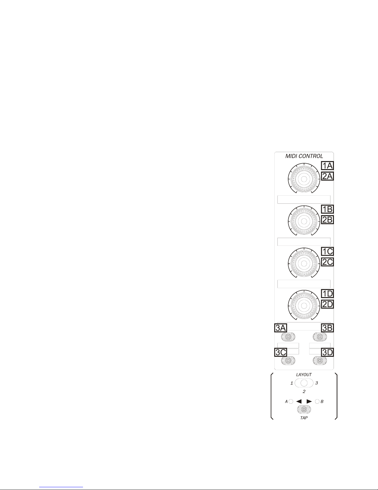
6.3. Dedicated MIDI control area
The NUO4 has 12 controls exclusively dedicated to send MIDI messages:
• 4 rotary controls (1A - 1D)
• 4 buttons (integrated to the rotary controls) (2A - 2D)
• 4 buttons (3A - 3D)
LAYOUT and A/B selectors do not send MIDI messages but allow the 12 controls
described above to send different messages. This multiplies the amount of messages
to be sent by specific MIDI controls.
A/B switch allows to double the 12 MIDI controls functions. A natural use for A/B switch
is to assign the same mixer button to a same function for two different channels in DJ
software.
For example, let's suppose that you have a DJ software with a mixer and two virtual
players. You want to assign PLAY to the 3B button; A/B switch allows you to send two
different MIDI messages and thus to execute the same function for each player. This
way you obtain:
• PLAY for left player: press 3B with switch in A position
• PLAY for right player: press 3B with switch in B position
LAYOUT selector allows you to send three different messages from each one of the 12
MIDI controls. Its natural use is to assign all the NUO4 MIDI section to three different
parts of DJ software.
For example, let's suppose that you want to control player, effects and sampler parts of
your DJ software. You'll distribute NUO4 MIDI controls this way:
• LAYOUT in position 1: control of DJ software player section
• LAYOUT in position 2: control of DJ software effect section
• LAYOUT in position 3: control of DJ software sampler section
13
Page 14

Therefore, 3B button could for example execute these functions:
• To activate PLAY: press 3B with LAYOUT in position 1
• To activate FLANGER: press 3B with LAYOUT in position 2
• To activate REC SAMPLER: press 3B with LAYOUT in position 3
In addition, with A/B switch described above, you can execute all these functions for a channel or another one in
your DJ software. This way:
• To activate REC SAMPLER for right player: press 3B with LAYOUT in position 3 and A/B switch in
position A
• To activate REC SAMPLER for left player: press 3B with LAYOUT in position 3 and A/B switch in
position B
In summary, LAYOUT and A/B combinations allow to send 6 different MIDI messages from each of the 12 NUO4
dedicated MIDI controls. Therefore, you can send a total of 72 different MIDI messages.
The controls of the specific MIDI control section can be related to any NUO4 MIDI channels (INPUT2 or INPUT3) or
can operate independently. If they operate as independent controls, they will always send MIDI messages even if
MIDI is not selected with these two channels input selectors. On the contrary, if a control is related to a specific
channel, it will only send MIDI messages with this channel in MIDI mode. This assignation is done with
Ecler Control 4 Lab software.
6.4. Real-time messages
6.4.1. MIDI Clock
The NUO4 transmits a standard timing message named MIDI Clock, to synchronize one or several external MIDI
devices. The synchronization signal is the same message sent 24 times per quarter note.
To control a MIDI device, remember this device has to operate in slave mode (external Clock).
The NUO4 has no internal processor for BPM calculation. The tempo for a specific musical part has to be manually
set, repeatedly pressing the TAP button (a minimum of 5 times) to the desired tempo. The TAP button blinks to the
BPM rate you established.
A more precise BPM adjustment can be done assigning one of the MIDI controls to this function with
Ecler Control 4 Lab software.
MIDI Clock can be deactivated by holding down the TAP button more than 3 seconds. When this happens, TAP
button does not blink. Once deactivated, it will not operate until you explicitly activate it by holding down the TAP
button more than 3 seconds. The selected mode will be maintained after shutdown.
Tempo default value is 120 BPM after each shutdown or MIDI Clock activation.
6.4.2. Start, Stop and Continue messages
When an external device is synchronized by MIDI Clock, standard Start, Stop and Continue messages are used to
control the playing.
Any NUO4 MIDI button can send these messages. Programming is done with Ecler Control 4 Lab software.
14
Page 15

7. MIDI CONTROL OPERATION
7.1. Drivers installation
To connect the NUO4 to a computer using USB-MIDI interface, you must previously install USB and MIDI drivers
(provided on the CD). The process varies according to the operating system in use. The only supported operating
systems are Windows® 2000 (SP4) and XP.
7.1.1. Windows® 2000
Warning: before connecting the NUO4 to its computer, please perform the following steps. Any other kind of
installation could cause the computer to unexpectedly reboot. This is due to certain peculiarities in Windows® 2000
concerning MIDI devices support through USB.
1. Before connecting the NUO4 to the computer for the first time, run 'install.exe' from the 'Driver' folder on the
CD.
2. When the installer screen comes up, check that the NUO4 is disconnected and press 'Yes' to continue.
3. The 'Digital Signature Not Found' error message may appear during USB driver installation. If it does, click
YES to proceed with installation.
4. Restart your computer when the wizard tells you to do so.
5. After restart, connect the USB cable between the NUO4 and the computer.
6. The operating system will automatically detect the device. There may be a long pause while the operating
system detects the device until the end of the process.
7. Again, if the 'Digital Signature Not Found' error message appears, click YES to proceed with installation
8. Once the process completed, the NUO4 is identified as 'Ecler USB Midi' by the operating system.
9. To safely disconnect NUO4 USB cable, follow the Windows® 2000 standard method to 'Unplug or eject
hardware'. If the USB cable is directly removed a warning appears to inform you that the device extraction
has not been safely done.
7.1.2. Windows® XP (home or professional)
1. Check that the NUO4 USB cable is disconnected and start your computer.
2. Run 'install.exe' program form the “Driver” folder on the CD.
3. Install program will request the user to connect the NUO4 USB cable to the computer and to wait until the
operating system completes the drivers automatic default installation. Do not click 'Accept' until
Windows® XP tells you that the new device is ready to use (If you do it before, the installer tells you that he
can't complete installation and you have to restart the computer before retrying. Carefully follow all the
steps indicated in this manual). Caution: There may be a long pause while the operating system
detects the device until the end of the process.
4. Once Windows® XP tells you that the new device is ready to use, click 'Accept' to proceed with installation.
5. If XP Logo testing warning windows appears indicating that the driver you're going to install is not certified,
click 'Continue anyway' to proceed with installation.
6. Once the process completed, the NUO4 is identified as 'Ecler USB Midi' by the operating system and is
ready to use.
15
Page 16

ATTENTION: With Windows® XP, if you connect the NUO4 to different USB ports on your computer, you'll have to
repeat the installation for each port and to restart your equipment each time. On the contrary, if you use
Windows® 2000 and connects the NUO4 to different USB ports on your computer, you won't have to repeat the
installation for each one of them, the system automatically identifies them.
We recommend visiting Ecler's web page (www.eclerdjdivision.com) in order to check if driver or software updates
are available.
7.1.3. NUO4 driver uninstall
In order to uninstall NUO4 drivers from any operating system, disconnect first NUO4 USB cable from the computer.
Run 'uninstall.exe' program from the 'Driver' folder on the CD.
1. Follow the wizard instructions.
2. Once the process completed, NUO4 USB-MIDI drivers are uninstalled from your operating system.
This utility uninstalls drivers for all ports on the same computer.
7.2. Controls programming
A same MIDI control can be configured to send different types of message depending on the specific needs of the
external device the user has to control. Programming is done from Ecler Control 4 Lab software.
7.2.1. Rotary controls
The different messages MIDI rotary controls can send are:
• Incremental control: it sends a control change message with the value increase to be done on the related
control; if it is rotated to the right, increments are sent (value 1 to 4) and if it is rotated to the left,
decrements are sent (value -1 to -4). This type of message is well suited for NUO4 MIDI rotary controls 1A
to 1D when you want to manipulate rotary or sliding controls, since they correctly operate independently of
the absolute position they have.
• Absolute control: it sends a control change message with the current absolute value the related control
must have. The value range is 0 (completely to the left) to 127 (completely to the right). The rotary and
sliding controls of NUO4 channels 2 and 3 only accept this mode. Although this mode is not so useful with
NUO4's MIDI controls 1A to 1D, it has been implemented for compatibility.
• Two unlatch buttons: turning to the right sends a Note-On/Off message and turning to the left sends a
different one. This type of message is well suited when you want to control a pair (like up/down, +/-…) with
a rotary button.
• Any NUO4 MIDI control 1A to 1D can be used to finely adjust the tempo (BPM). In this mode no MIDI
command is sent.
16
Page 17

7.2.2. Control buttons
The different MIDI messages that control buttons can send are:
• Unlatch button (normal push switch): it sends two different note messages (Note-On when pressed and
Note-Off when released). It is well suited to control functions needing a temporary state change while the
button is pressed. An example is pitch adjustment that you activate as long as the button is pressed.
• Latch button (toggle push switch): it sends only one Note-on message whenever it is pressed. It is
appropriate when you want to control functions needing a permanent state change when pressing the
button. An example is the play function of a CD player that is activated by a simple pressing on the button
and vice versa.
• Any NUO4 MIDI button can send real-time messages (Start, Stop and Continue). Programming is done
with Ecler Control 4 Lab software.
7.2.3. Recommendations
As starting point we recommend to configure all rotary controls in incremental mode and buttons in momentary
mode, and to match your software MIDI control configuration to obtain optimal operation.
If your software does not allow suitable settings of these controls, try to modify the MIDI message that the NUO4
sends with Ecler Control 4 lab.
7.3. Assignment advice for external device functions
There is no universal method to assign functions, since each external device has its own particularities.
Our first advice is to spend the necessary time for indepth knowledge of MIDI control capabilities and how to
program them. Most of the external devices with MIDI control can be set; it means you can define the message
each control will respond to.
The second step consists of choosing the external device functions to control and assigning them to the NUO4
MIDI controls. As you should consider different aspects, we pointed out some of the most relevant ones:
• Allocate controlled functions in a logical manner, grouping them by blocks in the three LAYOUT sections
(1/2/3). For example, try to group all player-related functions in a same LAYOUT (Play, Cue, Pitch Up...),
all the effect-related ones in another LAYOUT (Flanger, Echo, Delay...).
• Consider if certain functions have to be kept on the same button independently of LAYOUT position. For
example, if you want the 3B button to execute the PLAY function whatever the LAYOUT and A/B selectors
position is.
• Think if you want to use channels 2 and 3 in analog or MIDI mode.
In order to reach these objectives, you'll probably need to first edit the NUO4 internal programming and to correctly
configure the external device. From Ecler Control 4 Lab check (and if necessary correct):
• that the NUO4 controls send the appropriate type of message to execute the desired function in the
external device
• that the MIDI channel used by the NUO4 is the appropriate one for your external device
• that messages are the appropriate ones for your external device
• that controls having a same function send identical messages
17
Page 18

Once the configuration has been set up, update your mixer firmware. Then configure your external device so that it
responds to MIDI messages the NUO4 sends. Each external device has its own learning method:
• select the MIDI learning mode
• choose a function on the external device
• move a NUO4 control to send a MIDI message
• the external device combines this MIDI message with that function and store it
7.4. Label printing
Once concrete functions have been assigned to NUO4 MIDI controls, you'll have to identify each button's function.
For this, the NUO4 incorporates an innovative label system.
On the Ecler Control 4 Lab CD-ROM, you'll find a folder dedicated to label printing with two files: one
Microsoft® Word file (.doc) and one CorelDRAW® file (.cdr).
Type the name of the functions that are assigned to MIDI controls and print labels, preferably on transparent paper.
Trim the labels and place them in front of the windows of the magnetized plate through lateral grooves.
8. FURTHER CONSIDERATIONS
8.1. Ground loops
Ensure at all times that no signal sources reaching the mixing desk and no devices connected to its output have
their earths interconnected; that is, earth should never reach them via two or more different paths, as this could
lead to humming which could even interfere with sound reproduction quality. In order to avoid earth loops, ensure
that the shielding of cables, if connected to the chassis, are never connected with each other.
When you connect computer and sound equipment, 'hum' frequently appears, caused by an earth loop. In this
case, it is usually advisable to make the connection through an accessory known as earth loop eliminator, available
in specialized shops.
8.2. Audio connections
As a general rule of thumb, make the signal connections as short as possible and use the best connectors and
cable available. Cables and connectors are frequently held cheap, forgetting that a bad connection can result in a
poor sound quality.
8.3. Background noise
The use of active circuitry can yield, depending on the configuration, to a significant noise level. The NUO4 has
been designed for the minimum possible noise. Anyway, the noise level will always depend on the correct use and
installation of the mixer. It is not the same setting up the FADER at "2" and the MASTER at "10" that the other way
round; FADER at "10" and MASTER at "2". In the first case you get a poor signal to noise ratio that will be fully
amplified by the master while on the second we have a good signal to noise ratio only amplified by "2". As a result,
the background noise is greater in the first case than in the second one.
8.4. Cleaning
The front panel should not be cleaned with dissolvent or abrasive substances because silk-printing could be
damaged. To clean it, use a soft cloth slightly wet with water and neutral liquid soap; dry it with a clean cloth. Be
careful that water never gets into the unit through the holes of the front panel.
18
Page 19
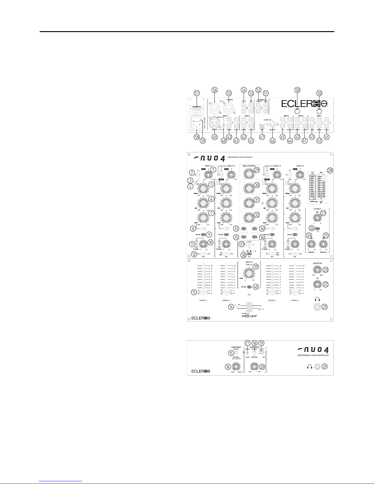
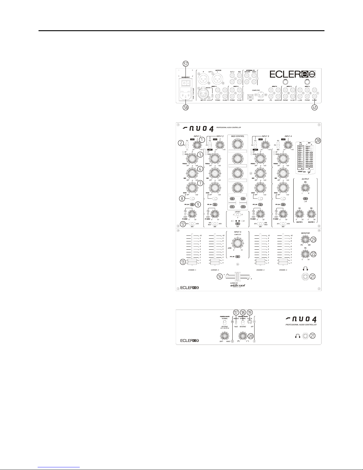
9. FUNCTION LIST 10. FUNCTION DIAGRAM
1. Input sensitivity adjust, GAIN
2. Input selector
3. Signal present indicator, SP
4. Peak level indicator, PEAK
5. Treble frequency control, TREBLE
6. Midrange frequency control, MID
7. Bass frequency control, BASS
8. Bass frequency isolation switch
9. Prefader listening control, PFL
10. Effect send control, FX SEND
11. Send switch to effect bus
12. Send to XF switch, XFA/MIX/XFB
13. Fader
14. Crossfader
15. Fader reverse function
16. Crossfader Shape adjuster, SOFT HARD
17. Crossfader curve mode, SWITCH FADE
18. Crossfader reverse function
19. Crossfader "cut in time" adjustment, CUT IN
20. Crossfader Shape adjuster
21. Headphones stereo jack connector
22. Headphones volume control, VOL
23. PFL/MIX monitoring crossfade
24. Output 1 level control, MASTER 1
25. Output 2 level control, MASTER 2
26. Left and Right signal sum, L+R
27. Balance control, BAL
28. PFL and MIX vu-meter
29. MIDI rotary control
30. MIDI rotary control
31. MIDI rotary control
32. MIDI rotary control
33. MIDI button
34. MIDI button
35. MIDI button
36. MIDI button
37. LAYOUT Selector
38. A/B switch
39. Input 5, LEVEL control
40. Pre-fader listening control, PFL
41. High Line RCA inputs, H-LINE
42. Turntable phono RCA inputs, PHONO
43. Low Line RCA inputs, L-LINE
44. RCA inputs for computer, AUDIO IN
45. RCA inputs for computer, PFL
46. MIDI OUT
47. USB port
48. Micro input sensitivity switch
49. Microphone input, MICRO
50. Ground pin, GND
51. External effect SEND output, SEND
52. External effect RETURN input, RETURN
53. Recording RCA connector, REC
54. RCA output, OUT2
55. Left channel balanced output, OUT1 L
56. Right channel balanced output, OUT1 R
57. Mains OFF/ON Switcher, O/I
58. Mains socket
59. Fuse holder
19
Page 20

Contenido del manual
1. NOTA IMPORTANTE 21
1.1. Instrucciones de seguridad 21
1.2. Descripción de la garantía 21
2. INTRODUCCIÓN 22
3. INSTALACIÓN 22
3.1. Conexiones de entrada de audio 23
3.2. Conexiones de salida de audio 24
4. INICIO RÁPIDO 25
5. OPERACIÓN Y USO 26
5.1. Puesta en funcionamiento 26
5.2. Descripción de los controles 26
6. CONTROLES MIDI 29
7. USO DEL CONTROL MIDI 32
8. OTRAS CONSIDERACIONES 35
9. LISTA DE FUNCIONES 36
10. DIAGRAMA DE FUNCIONES 36
11. CARACTERÍSTICAS TÉCNICAS 71
12. DIAGRAMAS 72
12.1. Figuras 72
12.1.1. Diagrama de conexiones 72
12.1.2. Sistema de montaje en rack 73
12.1.3. Configuración interna de los jumpers 74
13. DIAGRAMA DE BLOQUES 75
Todos los datos están sujetos a variación debida a tolerancias de producción. ECLER S.A. se reserva el derecho de realizar
cambios o mejoras en la fabricación o diseño que pudieran afectar las especificaciones.
20
Page 21
1. NOTA IMPORTANTE
1.1. Instrucciones de seguridad
Para conseguir la máxima funcionalidad del aparato y su máximo rendimiento, es muy importante antes de su
conexión, leer detenidamente y tener muy presentes las consideraciones que en este manual se especifican. Para
garantizar el óptimo funcionamiento de este aparato, recomendamos que su mantenimiento y eventuales
reparaciones sean llevadas a cabo por nuestros Servicios Técnicos autorizados.
Este aparato debe conectarse a tierra a través de su cable de red.
No exponer la unidad a la lluvia o a salpicaduras de agua, no colocar recipientes que contengan líquidos
u objetos incandescentes tales como velas sobre el aparato. No obstruya las rejillas de ventilación.
Cualquier cambio en la configuración de la unidad debe ser llevado a cabo por técnicos cualificados. Cualquier
conexión o desconexión de la unidad debe ser realizada, siempre, con la unidad desconectada de la red.
1.2. Descripción de la garantía
Su equipo ECLER ha superado ensayos de laboratorio y exhaustivos controles de calidad antes de abandonar la
fábrica. No obstante podría darse el caso que necesite nuestro Servicio Técnico durante el periodo que cubre la
garantía o posteriormente. En tal caso, proteja cuidadosamente la unidad en su caja original y envíelo a nuestro
Servicio Técnico con los gastos y el seguro pagados. Adjunte una fotocopia del certificado de garantía y una
descripción detallada del defecto observado.
ECLER, S.A. garantiza sus productos ECLER ante defectos de materiales o fabricación durante el periodo de UN
AÑO (TRES AÑOS en el caso de mezcladores de las series SCLAT y NUO y en los amplificadores de tecnología
SPM y CINCO AÑOS para los potenciómetros ETERNAL) transcurridos tras la fecha de compra original.
ECLER, S.A. reparará el equipo defectuoso dentro del periodo especificado, sin cargo alguno para piezas y mano
de obra.
Para asegurar la validez de la garantía es preciso que la Garantía y la Tarjeta de Registro se rellenen
correctamente y se remitan a su distribuidor ECLER, en el plazo de 10 días después de la fecha de compra.
La garantía no es transferible y solamente protege al comprador original.
La garantía no cubre:
- Daños ocasionados por malos tratos o manejo negligente, falta de cuidados elementales, desatención de las
instrucciones del manual, conexión equivocada o accidentes.
- Aparatos que hayan sido manipulados, alterados o reparados fuera del Servicio Técnico autorizado.
- El mueble exterior, los componentes electromecánicos ni su desgaste por uso.
- Los gastos de envío y seguros, ni los daños que el aparato pueda sufrir durante el transporte.
ECLER, S.A., no será responsable por ningún daño directo o indirecto, pérdida o perjuicio originado por o en
relación con el equipo.
Esta garantía es válida sólo si las reparaciones o servicios se realizan en un Servicio Técnico autorizado.
21
Page 22
2. INTRODUCCIÓN
¡Felicidades! Por adquirir un auténtico equipo profesional ECLER. El NUO4 ha sido diseñado cuidadosamente en
colaboración con prestigiosos artistas, DJs y productores, desarrollado con componentes de última generación y
fabricado en nuestra planta de Barcelona bajo estrictos controles de calidad.
El NUO4 es un mezclador estéreo de cinco canales con capacidad para 11 fuentes de sonido.
Debido a su formato y robustez, el NUO4 está principalmente concebido para aplicaciones de mezcla profesional
(club, estudio...) donde se requiere un mezclador de tamaño compacto pero excelentes prestaciones.
3. INSTALACIÓN
La principal consideración a tener en cuenta en el momento de buscar la ubicación de su nuevo NUO4 debe ser la
máxima comodidad de trabajo del operador, permitir una total facilidad en la realización de las conexiones de las
que el mezclador va a ser punto de partida y llegada. El NUO4 está básicamente concebido como mezclador de
sobremesa y su ubicación habitual será entre dos reproductores de discos compactos o de vinilo. El mezclador
tiene un formato de 14.57'' (37 cm) de profundidad y 12.6'' (32 cm) de anchura. Mediante el kit de laterales
metálicos (disponibles como opción) (Fig. 1) podrá sujetar firmemente su NUO4, ya sea directamente sobre la
superficie sobre la que se apoye o sobre los laterales, también le permitirán inclinar el mezclador. Existe otra
opción de perfiles metálicos "NUORAKI" que permiten la ubicación del mezclador en muebles rack estándar de
19".
Dada la elevada ganancia de las entradas de PHONO y de MICRÓFONO debe procurarse situar el mezclador lo
más alejado posible de fuentes de ruido (variadores de tensión, motores, etc.) así como de cualquier cable de red.
Por esta misma razón y bajo ninguna circunstancia debe quitarse la tapa metálica del aparato.
Ya que el consumo del NUO4 es muy bajo, éste no precisa ventilación, sin embargo debe evitarse que esté
expuesto a una temperatura extrema y que la atmósfera del local en que esté emplazado sea lo más seca y limpia
de polvo posible.
El NUO4 funciona con una fuente de alimentación conmutada de tipo universal permitiendo trabajar sin ningún tipo
de ajuste desde 90V a 264V – 47/63Hz. Asegúrese de que el cable de red se encuentre lejos de los cables de
señal para evitar zumbidos.
Para proteger al mezclador de eventuales sobrecargas en la línea de red existe un fusible de red de tipo T 500mA.
En caso de que éste se fundiera se desconectaría el aparato y se sustituiría por otro de idénticas características.
Si éste último se volviera a fundir, consulte con nuestro Servicio Técnico.
ATENCIÓN: EN NINGÚN CASO DEBE CORTOCIRCUITAR EL CIRCUITO DE PROTECCIÓN O
PONER UN FUSIBLE DE VALOR MÁS ELEVADO.
ADVERTENCIA: La sustitución del fusible debe ser realizada por un técnico cualificado.
22
Page 23

3.1. Conexiones de entrada de audio
Input 1 H-LINE Reproductor CD
Input 1 PHONO Plato giradiscos
Input 1 L-LINE Ordenadores, Magnetófonos...
Input 2 H-LINE Reproductor CD
Input 2 PHONO Plato giradiscos
Input 3 H-LINE Reproductor CD
Input 3 PHONO Plato giradiscos
Input 4 PHONO Plato giradiscos
Input 4 H-LINE Reproductor CD
Input 4 MIC Micrófono
Input 5 (computer) AUDIO IN Tarjeta de sonido
PFL Preescucha
- Entradas de Phono:
Los platos giradiscos deben ir equipados con cápsula magnética con un nivel de salida nominal entre –55dBV y
-25dBV (1,77 a 56mV). Las entradas PHONO (42) del NUO4 tienen un amplio margen antes de la saturación
(headroom) y pueden admitir cápsulas con mayor nivel de salida de lo habitual. Estas entradas presentan una
sensibilidad de entrada nominal de –40dBV (10mV). El NUO4 dispone de dos bornes de masa
sobredimensionados para conectar el cable de tierra de los platos giradiscos.
- Entradas de Línea:
Dadas las importantes diferencias de nivel existentes entre las Fuentes del tipo CD y de LINE convencional, el
NUO4 incorpora entradas diferenciadas para cada uno de estos elementos. Así la sensibilidad de las entradas
marcadas como HIGH LINE (41) es 0dBV (1V) y la de LOW LINE (43) es -10dBV (316mV). Reproductores CD,
DAT, MP3, DVD Audio... se conectarán a las entradas HIGH LINE. Magnetófonos, cassettes, sintonizadores, y
algunos equipos de producción (samplers, secuenciadores) se conectarán a la entrada LOW LINE.
- Entradas de Micrófono:
La entrada de MICRO (49),está preparada para un nivel nominal de entrada de -50dBV (3.16mV). La conexión es
del tipo XLR3. A través del conmutador ubicado en el panel posterior (48), en posición MIC. ATT efectúa una
reducción de 20dB de la sensibilidad de esta entrada, pasaría pues de –50 a –30dB (3.16 a 31.6mV). Esta entrada
de micrófono admite la conexión en modo balanceado para ello se realizará la conexión tal y como se indica:
Vivo o señal directa > Terminal 2
Frío o señal invertida > Terminal 3
Masa > Terminal 1
Los micrófonos deben ser de baja impedancia (de 200 a 600Ω) y monofónicos. Para conexiones NO balanceadas
cortocircuitar a masa el terminal 3. El NUO4 dispone de alimentación phantom para micrófonos equipados de
condensador. Un jumper interno permite inhibir el funcionamiento de la alimentación phantom. La entrada MICRO
del NUO4 se sirve de fábrica con el jumper interno en posición "phantom ON". Ver diagrama de configuración.
- Entrada computer
AUDIO IN: La sensibilidad nominal de esta entrada es de -10dB, para una correcta adaptación al nivel de salida de
las tarjetas de sonido, permite un ajuste entre -∞ y 0dB de ganancia.
PFL: Tiene una sensibilidad nominal de 0dB. Esta entrada esta prevista para la preescucha de los programas de
mezcla de audio sobre ordenador. Debe conectarse a una segunda salida de la tarjeta de sonido.
23
Page 24

3.2. Conexiones de salida de audio
Out 1 Amplificador de potencia principal
Out 2 Amplificador de cabina
Rec Dispositivo grabador
External FX Procesador de efectos externo
(Send y Return) (Entrada y Salida)
Monitor Auriculares
- Master Output 1:
Estas salidas estéreo alimentan al sistema de P.A. a través de conexiones XLR3 balanceadas. El nivel nominal de
la salida OUT1 (55-56) está ajustado a 0dBV (1V), pero puede elevarse a +6dBV (2V) mediante puentes internos.
El nivel de salida OUT 1 se controla con el potenciómetro MASTER 1 (24).
- Master Output 2:
Habitualmente se usa para obtener una salida independiente en la cabina del DJ. Esta salida estéreo OUT 2 (54)
incorpora conexiones RCA no balanceadas y su nivel nominal de salida está ajustado a 0dBV (1V), pero puede
elevarse a +6dBV (2V) mediante puentes internos. El nivel de salida OUT 2 se controla con el potenciómetro
MASTER 2 (25).
OUT 1 y OUT 2 disponen adicionalmente de un control de balance BAL (27) y un conmutador mono estéreo L+R
(26) común a ambas salidas.
- Salida de grabación:
Esta salida emplea conexiones RCA. REC (53) se encuentra situada en el panel posterior. El nivel de salida
nominal de la salida REC es de 0dBV (1V).
- Bucle externo:
Las conexiones de tipo RCA de salida EXTERNAL FX SEND (51) y de entrada RETURN (52) permiten la
realización de un bucle externo con cualquier efecto, sampler o dispositivo secuenciador. La señal enviada a la
salida EXTERNAL FX SEND se selecciona antes o después del FADER mediante el conmutador FX SEND (11) y
el nivel con su potenciómetro asociado (10).
El nivel nominal de la salida SEND, así como la entrada RETURN es de 0dBV (1V).
- Auriculares:
Para obtener el mejor rendimiento en su funcionamiento, éstos deberán ser de alta impedancia (200-600Ω). Se
conectarán a una de las dos salidas MONITOR (21) situadas en la placa frontal o sobre la propia placa de mandos
mediante un conector jack normalizado de ¼" estereofónico. El casquillo del jack será la masa, el anillo central el
canal derecho y la punta el canal izquierdo.
24
Page 25

4. INICIO RÁPIDO
Instale y conecte el NUO4 tal y como se describe en el primer párrafo del apartado INSTALACIÓN.
Se describe a continuación un procedimiento de “inicio rápido” usando la entrada H-LINE del canal 1 junto a una
monitorización a través de la salida de auriculares.
1º Ajuste los controles de canal. Sitúe el conmutador
de entrada (2) en H-L. Ajuste los controles rotativos
GAIN, TREBLE, MID y BASS (1, 5, 6 Y 7) en su
posición central enclavada. Posicione el conmutador
BASS OFF (8) en su estado levantado (BASS ON).
Sitúe el fader de canal (13) abajo y asigne el selector
XFA/MIX/XFB (12) en posición XFA (el canal está
asignado ahora al lado A del crossfader).
2º Ajuste el MONITOR VOL (22) al mínimo y lleve el
control MONITOR PFL/MIX (23) a su posición MIX.
3º Conecte un reproductor de CD en la entrada
H-LINE del canal 1 (41).
4º Conecte unos auriculares a la salida MONITOR
(21).
5º Conecte el cable de alimentación (58) en la parte
trasera del mezclador y enciéndalo (57).
6º Compruebe que se ilumina el LED POWER situado
bajo el VU-Metro (28).
7º Inicie la reproducción de una pista del CD.
8º Presione el botón con LED amarillo PFL (9) del
canal 1 y ajuste el GAIN hasta que el VU-Metro
izquierdo marque 0dBV.
9º Coloque el fader de canal (13) arriba y sitúe el
crossfader (14) en el lado "A".
10º Ajuste el MONITOR VOL (22) para obtener un
nivel de escucha confortable en sus auriculares.
11º Compruebe el potente ecualizador estéreo de 3
bandas (5-6-7). El ecualizador está diseñado para la
modificación creativa del sonido: cada banda puede
aislarse independientemente (OFF) mediante los
grandes controles rotativos ergonómicos y el
conmutador BASS OFF permite un rápido efecto "kill"
sobre las bajas frecuencias.
12º Compruebe el funcionamiento del crossfader (14).
La posición MIX provoca que la señal no se vea afectada por el crossfader. El crossfader permite realizar un
fundido entre las señales asignadas a ambos lados A y B del mismo. El movimiento del crossfader permite crear
un fundido suave entre pistas de música o rápidos cortes de sonido tipo “scratch”. La curva de fundido se puede
ajustar de manera muy precisa gracias a los controles CUT IN* (19) (punto de fade in), el selector SWITCH / FADE
(17) (curva redondeada o cuadrada), el selector REVERSE (18) (se invierte el comportamiento del crossfader) y el
control fino de curva (20).
Para más detalles, consulte por favor el resto de este manual.
* Solo en el caso de montar el crossfader "eternal".
25
Page 26

5. OPERACIÓN Y USO
5.1. Puesta en funcionamiento
Esta se realizará mediante el interruptor (57) situado en el panel posterior, al cabo de unos instantes se iluminará
el LED inferior, POWER, del VU-metro. Aunque el ruido producido por la puesta en funcionamiento del NUO4 es
mínimo y queda prácticamente anulado al hacerlo con los faders cerrados, siempre resulta muy recomendable
poner en marcha todos los aparatos siguiendo la secuencia siguiente:
1. Fuentes de sonido
2. Unidad de mezclas, ecualizadores, filtros activos
3. Finalmente, amplificadores de potencia.
El paro de los aparatos debe realizarse en la secuencia inversa. Siguiendo este orden los picos o transitorios
producidos por el encendido o apagado de los aparatos no afecta a los siguientes y, por consiguiente, tampoco
llegan a los altavoces.
5.2. Descripción de los controles
5.2.1. Selector de entrada
Cada canal principal dispone de un selector de entrada basculante (2).
5.2.2. Ganancia de vía
Todas las vías de entrada del NUO4 disponen de un ajuste accesible de la sensibilidad de entrada GAIN (1), cuya
misión es la de compensar las diferencias de nivel existentes entre las fuentes sonoras conectadas a la mesa
antes de ser mezcladas. Los ajustes de ganancia deben realizarse con suma meticulosidad utilizando los LEDs de
SP (Signal Present) (3) y PEAK (2), el VU-Metro y/o los auriculares como referencia. El nivel de referencia
estándar usado para mezclar señales de audio es de 0dBV. Para obtener una mezcla óptima, ajuste su entrada a
un valor lo más cercano posible a 0dBV leído en el VU-Metro PFL y asegúrese de no alcanzar nunca el nivel de
"clipping", tomando como referencia de los LEDS rojos de aviso PEAK de cada canal.
5.2.3. Ecualización
El sistema de control de tonos para cada vía ofrece un amplio margen de actuación: -30 a +10dB para la vías de
graves (7) y agudos (5) y -25 a +10dB para la vía de medios (6). Este amplio margen de variación ha sido
especialmente diseñado para el uso creativo en directo. Adicionalmente, las bajas frecuencias se pueden “matar al
vuelo” por medio del conmutador BASS OFF (8) situado debajo de cada control rotativo BASS.
ATENCIÓN: Utilice el control de tonos con precaución, la elevada ganancia máxima puede provocar
sobredesplazamientos en su sistema de altavoces.
5.2.4. Sistema de monitorización
El NUO4 está equipado con un sistema de monitorización flexible y sencillo que permite ajustar con suma
precisión los niveles de PFL (monitorización de escucha pre-fader) y de mezcla para cada vía de entrada principal
a través del VU-Metro y de los auriculares.
Cada canal puede ser monitorizado visualmente y pre-escuchado pulsando los botones PFL (9), iluminados de
color amarillo.
Para la monitorización a través de auriculares, el potenciómetro rotativo PFL/MIX (23) permite mezclar un PFL
seleccionado con la mezcla principal de programa MIX. El potenciómetro rotativo VOL (22) controla el nivel de
salida de auriculares.
El NUO4 puede visualizar en su display (28) la señal PFL L+R (en la primera columna del VU-metro) junto con el
nivel de mezcla izquierda y derecha (segunda y tercera columna del VU-metro).
26
Page 27

5.2.5. Envío a unidades exteriores de efectos, FX SEND
Las 4 vías principales del NUO4 están equipadas con potenciómetros rotativos (10) que permiten realizar un envío
a una unidad de efectos exterior, sampler, rever... Estos potenciómetros permiten dosificar el nivel de señal que se
envía de cada una de las vías. La salida SEND (51) se conectará a la entrada del efecto y la salida de éste puede
conectarse a la entrada RETURN o a una entrada LINE.
Este envío puede configurarse mediante el conmutador basculante PRE/POST (11) para que el envío esté o no
afectado por el fader de vía.
5.2.6. Faders de canal
El NUO4 monta una nueva generación de faders ECLER de 60 mm (13) precisos, extremadamente suaves, con
un “cut in time” súper rápido y unas prestaciones que superan los 4.000.000 de maniobras combinados con el
sistema VCA de ECLER (VCA: Voltage controlled Amplifier).
La utilización de VCA’s posibilita la modificación del comportamiento del fader. En la sección FADER SHAPE de la
placa frontal existen dos controles: el conmutador NORMAL/ REVERSE (15) permite invertir el funcionamiento del
fader, 0 vía abierta, 10 vía cerrada en los canales 1 y 4. El potenciómetro rotativo SOFT/HARD (16) permite
regular la curva entre estos dos extremos, entrada suave o entrada brusca en los cuatro canales principales.
Los cuatro canales pueden ser direccionados hacia el CROSSFADER del NUO4 gracias a los conmutadores
basculantes (12). "XFA" asigna el canal al lado A, del crossfader mientras que la posición "MIX" significa que el
canal no se verá afectado por el crossfader, sino asignado a la mezcla principal siempre.
5.2.7. Crossfader / Crossfader "eternal" adaptable
Si desea extender la vida útil de su crossfader, el NUO4 permite el montaje como opción del galardonado
potenciómetro Eternal.
El Crossfader ECLER ETERNAL emplea tecnología inductiva basada en un sistema de control magnético. Una
pantalla de aluminio extremadamente ligera (0,5gr) corta al desplazarse las líneas de campo magnético generadas
entre dos juegos de bobinas. La variación de flujo electromagnético comanda a su vez un amplificador controlado
por tensión que se encargará, directamente, de actuar sobre la señal de audio. Esta tecnología totalmente libre de
contactos combinada con un sistema mecánico exclusivo de deslizamiento dan como resultado un tacto suave y
uno de los crossfaders más precisos existentes en la actualidad. El concepto ETERNAL tiene ventajas obvias con
relación a otros sistemas existentes que utilizan tecnología óptica. A diferencia de los sistemas ópticos, el
concepto inductivo es resistente al humo, humedad, temperatura y envejecimiento. El crossfader inductivo
ETERNAL ha sido concebido específicamente para ejecutar técnicas de “turntablism”.
El crossfader del NUO4 incorpora una serie de controles agrupados en la sección XFADER SHAPE que permiten
“afinar” su comportamiento convirtiéndolo en una precisa herramienta:
SELECTOR SWITCH/FADE (17). Dependiendo de lo “afilados” que deban ser los “scratches” el NUO4 posibilita la
selección entre los modos FADE (fundido) o SWITCH (interruptor). En modo FADE se obtiene una curva muy
progresiva mientras que en modo SWITCH su comportamiento es prácticamente el de un interruptor, óptimo para
rápidos “scratches”. Además ambos modos pueden ajustarse de forma “fina” mediante el potenciómetro de ajuste
asociado (20).
El conmutador NORMAL/REVERSE (18), también denominado HAMSTER, invierte la dirección normal del
crossfader. Dependiendo de la dirección escogida pueden realizarse tanto “cuts” como “transforms” moviendo el
crossfader en la misma dirección.
La corrección electrónica del CUT IN (19) únicamente es efectiva en el caso de que el NUO4 haya montado el
potenciómetro "eternal" opcional. En caso de montar el XFADER estándar el potenciómetro CUT IN debe quedar
en posición OFF. El “Cut in time” es la distancia existente entre el final físico del crossfader y el primer punto de
entrada de señal. La posición más corta proporciona un “cut in time” prácticamente instantáneo, para encontrarla
el potenciómetro debe colocarse en posición extrema (programa musical totalmente atenuado) y el potenciómetro
CUT IN debe girarse a la derecha hasta que se obtenga señal musical. Para alargar el tiempo de “cut in time” girar
el potenciómetro hacia la izquierda.
27
Page 28

Tanto el potenciómetro estándar como el Eternal comparten el mismo tipo de conexionado, para instalar el
potenciómetro eternal siga el procedimiento descrito a continuación.
5.2.8. Faders y Crossfader con VCA reemplazables / Incorporación "eternal"
Una vez ha llegado al límite de vida útil cualquiera de estos elementos pueden ser fácilmente reemplazados
siguiendo los siguientes pasos:
1. Retire los botones y los tornillos de la carátula inferior.
2. Retire los dos tornillos del potenciómetro a reemplazar y extráigalo de su cavidad.
3. Desconecte el conector multiterminal.
4. Reemplace el elemento por otro igual o "eternal" en el caso del crossfader.
5. Conecte el conector multiterminal.
6. Colóquelo en su cavidad i sujételo con sus dos tornillos.
7. Coloque la carátula inferior con sus tornillos y botones
Utilice siempre repuestos originales ECLER.
5.2.9. Niveles MASTER
El NUO4 dispone de dos controles de nivel de salida principal MASTER 1 (24) y MASTER 2 (25). El nivel de
OUT 1 (55-56) se controla a través del potenciómetro MASTER 1. El nivel de OUT 2 (54) se controla a través del
potenciómetro MASTER 2.
El potenciómetro de balance BAL (27) afecta tanto a la salida MASTER 1 como a MASTER 2.
28
Page 29

6. CONTROLES MIDI
El NUO4 es un mezclador DJ que permite controlar dispositivos externos mediante el protocolo MIDI. Las
funciones MIDI asignadas a cada control son programables por el usuario mediante el software
Ecler Control 4 Lab.
MIDI (Musical Instruments Digital Interface) es un protocolo de comunicación estándar entre instrumentos
musicales electrónicos y ordenadores. Un dispositivo MIDI puede funcionar como esclavo (controlado) o como
maestro (controlador). El NUO4 trabaja como una unidad maestra, lo que significa que es capaz de controlar a
otros instrumentos musicales electrónicos (sintetizadores, secuenciadores, cajas de ritmo, software... e incluso
controladores de luz). Asimismo, el NUO4 puede recibir mensajes MIDI pero únicamente para realizar funciones
de programación mediante el software Ecler Control 4 Lab.
La conexión MIDI OUT se realiza a través de un conector estándar del tipo DIN 5 pin (180º). El mezclador
incorpora también un interface USB-MIDI que permite enviar y recibir información MIDI entre el mezclador y un
ordenador utilizando el puerto USB.
Los mensajes MIDI del NUO4 pertenecen a la categoría de “Mensajes de Canal” y “Mensajes de Sistema”. Es
indispensable que los dispositivos emisor y recetor del mensaje utilicen el mismo canal para que puedan
comunicarse.
El NUO4 envía tres tipos de mensajes MIDI diferentes:
• Mensajes de disparo de notas (“Note-On” y “Note-Off”)
• Mensajes de cambio de control (“Control Change”)
• Mensajes de tiempo real (“System Real Time Messages”)
6.1. Conexionado
Disponemos de dos modos de conexión de entrada de audio de dispositivos externos controlables vía midi:
• Conectando el dispositivo externo al NUO4 a través de cualquier entrada H-LINE.
• Conectando el dispositivo externo al NUO4 a través de la entrada Input 5 (para la cual disponemos de un
control de volumen).
El conexionado de dispositivos cobra especial relevancia al trabajar con software DJ. Para ello, recomendamos
una tarjeta de sonido con al menos dos salidas.
Existen dos modos de operar un software DJ en conjunto con el NUO4:
• Utilizando el mezclador virtual del software DJ, el cual podremos controlar desde las vías 2 y 3 del NUO4
en modo MIDI. Dispondremos en este caso de dos salidas desde la tarjeta de sonido: una para la señal
MASTER y otra para la señal PFL, que conectaremos a las entradas INPUT 5 AUDIO IN y PFL
respectivamente de nuestro mezclador.
• Prescindiendo del mezclador virtual del software, utilizando así las vías 2 y 3 del NUO4 en modo
analógico. Dispondremos en este caso de dos salidas desde la tarjeta de sonido, que corresponderán a
los dos reproductores virtuales del software, los cuales conectaremos a cualquier entrada H-LINE.
6.2. Vías del mezclador con posibilidad de generar mensajes MIDI
Las vías 2 y 3 del NUO4, además de su uso analógico con PHONO y H-LINE, permiten enviar mensajes MIDI para
controlar dispositivos externos. Para ello debemos seleccionar la opción MIDI en el selector de entradas. La
aplicación principal a la que están orientados es el control de funciones equivalentes (GAIN, EQ, FADER...) de un
mezclador virtual en un software para DJ.
29
Page 30

Los controles MIDI disponibles en cada una de estas vías son:
• 5 controles rotativos que generan mensajes del tipo “Control Change” (GAIN, BASS, MID, TREBLE y
FX SEND)
• 2 controles deslizantes que generan mensajes del tipo “Control Change” (FADER y CROSSFADER)
• 2 conmutadores que generan mensajes del tipo “Note-On/Off” (BASS OFF y PFL)
Estos controles MIDI no se ven afectados por los selectores LAYOUT y A/B de la sección MIDI CONTROL.
Para que el crossfader funcione en modo MIDI al menos en una vía el selector de entradas y el de asignación del
crossfader de dicha vía deben estar simultáneamente en modo MIDI. Los controles de curvas no afectan al fader y
al crossfader al operar en modo MIDI. Puede haber ligeras diferencias entre la posición física de los controles
rotativos y deslizantes en el NUO4 y en el software.
La posición absoluta de los controles MIDI de las vías 2 y 3 no se actualiza de forma automática en el dispositivo
externo al seleccionar la posición MIDI en el conmutador de entradas. Los botones rotativos actualizan su posición
al moverse por primera vez, independientemente de la posición del control externo asociado.
Como alternativa, para actualizar todos los controles de una vía, pulse el botón TAP mientras acciona el modo
MIDI en el selector de entradas.
6.3. Zona específica de control MIDI
El NUO4 dispone de 12 controles dedicados exclusivamente al envío de mensajes
MIDI:
• 4 controles rotativos (1A a 1D)
• 4 pulsadores (incorporados en los controles rotativos) (2A a 2D)
• 4 pulsadores (3A a 3D)
Los conmutadores LAYOUT y A/B, incluidos en esta sección, no envían mensajes
MIDI sino que posibilitan que los 12 controles arriba descritos envíen mensajes
diferentes. De este modo multiplicamos la cantidad de mensajes que los controles
específicos MIDI pueden enviar.
El conmutador A/B nos permite duplicar las funciones de los 12 controles MIDI. El
cometido natural del conmutador A/B es el de asignar el mismo botón del mezclador a
una misma función en dos vías diferentes de un software DJ.
Por ejemplo, supongamos que disponemos de un software para DJ con un mezclador
y dos reproductores virtuales. Deseamos asignar la función PLAY al pulsador 3B; el
conmutador A/B nos permite distinguir dos mensajes MIDI diferentes y así ejecutar esa
misma función en cada uno de los reproductores. De este modo conseguimos:
• PLAY en el reproductor izquierdo: pulsar 3B con el conmutador en posición A
• PLAY en el reproductor derecho: pulsar 3B con el conmutador en posición B
El selector LAYOUT nos permite ejecutar tres funciones diferentes con cada uno de los
12 controles MIDI. La aplicación natural es asignar toda la sección MIDI del NUO4 a
tres bloques diferentes de un software DJ determinado.
Por ejemplo, supongamos que deseamos controlar los bloques de reproductor, efectos
y sampler de nuestro software DJ. Distribuiremos los controles MIDI del NUO4 de este
modo:
• LAYOUT en posición 1: control de la sección de reproductor del software DJ
• LAYOUT en posición 2: control de la sección de efectos del software DJ
• LAYOUT en posición 3: control de la sección de sampler del software DJ
30
Page 31

Así pues, el pulsador 3B por ejemplo podría ejecutar estas funciones:
• Activar PLAY: pulsar 3B con el LAYOUT en posición 1
• Activar FLANGER: pulsar 3B con el LAYOUT en posición 2
• Activar REC SAMPLER: pulsar 3B con el LAYOUT en posición 3
Además, de acuerdo con lo arriba descrito, con el conmutador A/B podemos ejecutar todas estas funciones en una
vía o en otra de nuestro software DJ. De este modo:
• Activar REC SAMPLER en el reproductor derecho: pulsar 3B con el LAYOUT en posición 3 y el
conmutador en posición A
• Activar REC SAMPLER en el reproductor izquierdo: pulsar 3B con el LAYOUT en posición 3 y el
conmutador en posición B
En resumen, la combinación de LAYOUT y A/B permite enviar 6 mensajes MIDI diferentes con cada uno de los 12
controles específicos MIDI del NUO4. Así pues, podemos llegar a enviar un total de 72 mensajes MIDI diferentes.
Los mandos de la sección específica de control MIDI pueden asociarse a alguna de las dos vías MIDI del NUO4
(INPUT2 o INPUT3) o bien funcionar con independencia de ellas. Si funcionan como controles independientes,
siempre enviarán mensajes MIDI aunque ninguna de las dos vías tenga seleccionado el modo MIDI en el selector
de entradas. Por el contrario, si relacionamos un control con una vía determinada, solo enviará mensajes MIDI
cuando dicha vía esté también en modo MIDI. Está asignación se hace mediante el software Ecler Control 4 Lab.
6.4. Mensajes de tiempo real
6.4.1. MIDI Clock
El NUO4 trasmite un mensaje estándar de sincronización denominado MIDI Clock, que permite sincronizar uno o
varios dispositivos MIDI externos. La señal de sincronización consiste en un mismo mensaje repetido regularmente
24 veces por cada BPM.
Para que un dispositivo MIDI pueda ser controlado, recuerde que deberá configurarlo para funcionar en modo
“esclavo” (Clock externo).
El NUO4 no dispone de procesador interno para el cálculo de BPM. La definición del tempo de un determinado
pasaje musical se realizará de forma manual pulsando el botón TAP repetidamente (un mínimo de 5 veces) al
ritmo que queramos imprimir. El botón TAP se ilumina al ritmo de los BPM que hayamos establecido.
Se puede realizar un ajuste más preciso de BPM destinando uno de los controles MIDI a esta función mediante el
software Ecler Control 4 Lab.
Se puede desactivar el MIDI clock pulsando el botón TAP durante más de 3 segundos. Cuando esto pasa, el botón
TAP no parpadea. Una vez desactivado no volverá a funcionar hasta que no se active explícitamente pulsando de
nuevo la tecla TAP durante más de 3 segundos. El modo seleccionado se conservará incluso tras apagar el
aparato.
Por defecto, después de cada encendido o bien al activar el MIDI Clock, el tempo será de 120 BPM.
6.4.2. Mensajes Start, Stop y Continue
Cuando un dispositivo externo está sincronizado mediante MIDI Clock, se utilizan los mensajes estándar Start,
Stop y Continue para controlar la reproducción.
Cualquier pulsador MIDI del NUO4 puede adjuntar estos mensajes. La programación se realiza mediante el
software Ecler Control 4 Lab.
31
Page 32

7. USO DEL CONTROL MIDI
7.1. Instalación de los drivers
Si desea conectar el NUO4 con un ordenador utilizando el interfase USB-MIDI, debe instalar previamente los
drivers para USB y MIDI que se suministran en el CD. El proceso varía según el sistema operativo que utilice. Los
únicos sistemas operativos soportados son Windows® 2000 (SP4) y XP.
7.1.1. Windows® 2000
Advertencia: antes de conectar el NOU4 a su ordenador siga los pasos que se indican a continuación. Cualquier
otra forma de instalación puede provocar un reinicio inesperado de su ordenador debido a ciertas peculiaridades
en el soporte de dispositivos MIDI a través de USB de sistema operativo Windows® 2000.
1. Antes de conectar el NUO4 al ordenador por primera vez, ejecute el programa "install.exe" que se
encuentra en la carpeta “Driver” del CD.
2. Cuando aparezca la pantalla del instalador asegúrese de que el NUO4 esta desconectado y pulse “Si”
para continuar.
3. Si aparecen avisos del sistema operativo indicando que el driver que va a instalar no está certificado pulse
“SI” a la pregunta de si desea continuar con la instalación.
4. Reinicie el ordenador cuando el asistente se lo indique.
5. Una vez reiniciado, conecte el cable USB del NUO4 al ordenador.
6. El sistema operativo detectará automáticamente el dispositivo. Puede haber una larga pausa desde que el
sistema operativo detecta el dispositivo hasta que termina el proceso.
7. Nuevamente, si aparecen avisos del sistema operativo indicando que el driver que va a instalar no está
certificado pulse “SI” a la pregunta de si desea continuar con la instalación.
8. Una vez terminado este proceso el NUO4 será detectado por el sistema operativo como “Ecler USB Midi”.
9. Si se desea desconectar el cable USB del NUO4 de forma segura utilice el método estándar para
“Desconectar o retirar hardware” de Windows® 2000. Si desenchufa el cable USB directamente aparecerá
la advertencia de que la extracción del dispositivo se ha realizado de forma no segura.
7.1.2. Windows® XP (home o professional)
1. Asegúrese que el cable USB del NUO4 esta desconectado y ponga en marcha su ordenador.
2. Ejecute el programa install.exe que se encuentra en la carpeta “Driver” del CD.
3. El programa de instalación le pedirá que conecte el cable USB del NUO4 al ordenador y espere hasta
que el sistema operativo complete la instalación automática de los drivers por defecto. NO pulse
“Aceptar” hasta que Windows XP no le indique que el nuevo dispositivo esta listo pasa usarse (Sí lo hace
antes, el instalador le indicara que no puede completar la instalación y que debe reiniciar el ordenador
antes de volver a intentarlo. Siga cuidadosamente todos los pasos indicados en este manual al pie de la
letra). Atención: Puede haber una pausa larga desde que el sistema operativo detecta el dispositivo
hasta que termina el proceso.
4. Una vez que Windows® XP le indique que el nuevo dispositivo esta listo pasa usarse pulse “Aceptar” para
continuar el proceso.
5. Si aparece un aviso del sistema operativo indicando que el driver que va a instalar no está certificado
pulse “Continuar” a la pregunta de sí desea continuar con la instalación.
6. Una vez terminado este proceso el NUO4 será detectado por el sistema operativo como “Ecler USB Midi”
y estará listo para su utilización.
32
Page 33

ATENCIÓN: Si utiliza Windows® XP y conecta el NUO4 en puertos USB diferentes de su ordenador deberá repetir
la instalación para cada uno de ellos y reiniciar su equipo cada vez. Por el contrario, si utiliza Windows® 2000 y
conecta el NUO4 en puertos USB diferentes de su ordenador NO deberá repetir la instalación para cada uno de
ellos, el sistema los identificara automáticamente.
Recomendamos visitar la página web de Ecler (www.eclerdjdivision.com) para comprobar si existen
actualizaciones de drivers o software.
7.1.3. Desinstalación de los drivers del NUO4
Para desinstalar los drivers del NUO4 en cualquier sistema operativo desconecte antes del ordenador el cable
USB del NUO4. Ejecute el programa “uninstall.exe” que se encuentra en la carpeta “Driver” del CD.
1. Seguir las instrucciones del asistente.
2. Una vez terminado el proceso los drivers USB-MIDI del NUO4 quedarán desinstalados de su sistema
operativo.
El programa desinstala el driver para todos los puertos de un mismo ordenador.
7.2. Programación de los controles
Un mismo control MIDI puede configurarse para enviar diferentes tipos de mensaje en función de las necesidades
específicas del dispositivo externo que utilice cada usuario. La programación se realiza desde el software
Ecler Control 4 Lab.
7.2.1. Controles rotativos
Estos son los distintos mensajes que pueden enviar los controles rotativos MIDI:
• Control incremental: envía un mensaje de cambio de control con el valor del incremento que debe realizar
el control asociado; si se gira a la derecha envía incrementos positivos (de valor 1 a 4) y si se gira a la
izquierda negativos (de valor –1 a –4). Este tipo de mensaje es el más indicado para los controles rotativos
MIDI 1A a 1D del NUO4 cuando se quiere manipular controles rotativos o deslizantes, puesto que operan
correctamente con independencia de la posición absoluta en que se encuentren.
• Control absoluto: envía un mensaje de cambio de control con el valor absoluto de la posición actual que
debe tener el control asociado. El valor está comprendido entre 0 (completamente a la izquierda) y 127
(completamente a la derecha). Los controles rotativos y deslizantes de las vías 2 y 3 del NUO4 solo
aceptan este modo. Aunque no resulta demasiado operativo utilizar los controles MIDI 1A a 1D del NUO4
en este modo, se ha implementado por compatibilidad.
• Dos pulsadores momentáneos: al girar a la derecha envía un mensaje de disparo de nota (Note-On/Off) y
al girar a la izquierda otro diferente. Este tipo de mensajes es el más indicado cuando se quiere controlar
con un botón rotativo funciones asociadas a una pareja del tipo Up/Down, +/-...
• Cualquiera de los controles MIDI 1A a 1D del NUO4 pueden utilizarse para realizar un ajuste fino de tempo
(BPM). En este modo no envía ningún comando MIDI.
33
Page 34

7.2.2. Controles de pulsación
Estos son los distintos mensajes que pueden enviar los controles de pulsación MIDI:
• Pulsador momentáneo (normal push switch): envía dos mensajes de disparo de notas (Nota-On al pulsar y
Nota-Off al soltar). Resulta apropiado cuando quiere controlar mediante un pulsador funciones que deben
cambiar de estado momentáneamente mientras se pulse el botón. Un ejemplo es el ajuste de pitch, que
activamos mientras pulsamos el botón.
• Pulsador enclavable (toggle push switch): envía un único mensaje de disparo de notas (Nota-On) cada vez
que se pulsa. Resulta apropiado cuando se quiere controlar mediante un pulsador funciones que deben
cambiar de estado y mantenerse así al pulsar el botón. Un ejemplo es el play de un reproductor, que
queda activado al dejar ir el pulsador y viceversa.
• Cualquier pulsador MIDI del NUO4 puede adjuntar los mensajes de tiempo real Start, Stop y Continue. La
programación se realiza mediante el software Ecler Control 4 Lab.
7.2.3. Recomendaciones
Como punto de partida recomendamos configurar todos los controles rotativos en modo incremental y los
pulsadores en modo momentáneo, y adaptar la configuración del control MIDI del software que utilicemos para
conseguir un funcionamiento óptimo.
Si el software no permite configurar adecuadamente estos controles, inténtelo modificando el mensaje MIDI que
envía el NUO4 mediante Ecler Control 4 lab.
7.3. Consejos para la asignación de funciones de dispositivos externos
No existe un método universal para la asignación de funciones, puesto que cada dispositivo externo tiene sus
propias particularidades.
Nuestro primer consejo es que invierta el tiempo necesario en conocer a fondo las posibilidades de control vía
MIDI del dispositivo externo y cómo se han de programar. La mayoría de los dispositivos externos con control MIDI
son configurables; es decir, se puede definir el mensaje al que responderá cada control.
El segundo paso consiste en elegir las funciones del dispositivo externo que desea controlar y repartirlas entre los
mandos MIDI del NUO4. Para ello hay que considerar diferentes aspectos, destacamos algunos de los más
relevantes:
• Distribuir las funciones que desea controlar de un modo lógico agrupándolas por bloques en las tres
secciones del LAYOUT (1/2/3). Por ejemplo, trate de agrupar todas las funciones relativas al reproductor
en un mismo LAYOUT (Play, Cue, Pitch Up...), todas las relativas a efectos en otro LAYOUT (Flanger,
Echo, Delay...).
• Considerar si hay determinadas funciones que deseamos mantener en un mismo botón
independientemente de la posición del LAYOUT. Por ejemplo, si deseamos que el pulsador 3B ejecute la
función PLAY independientemente de la posición de los selectores LAYOUT y A/B.
• Pensar si deseamos utilizar las vías 2 y 3 en modo analógico o MIDI.
Para conseguir estos objetivos posiblemente será necesario en primer lugar variar la programación interna del
NUO4 y configurar apropiadamente el dispositivo externo. Desde el software Ecler Control 4 Lab verifique y si es
necesario corrija:
• que los controles del NUO4 envían el tipo de mensaje apropiado para ejecutar la función deseada del
dispositivo externo
• que el canal MIDI utilizado por el NUO4 es el apropiado para su dispositivo externo
• que los mensajes son los apropiados para su dispositivo externo
• que los controles que realizan una misma función envían mensajes idénticos
34
Page 35

Una vez adaptada la configuración, actualice el firmware de su mezclador. A continuación configure su dispositivo
externo para que responda a los mensajes MIDI que envía el NUO4. Cada dispositivo externo dispone de un
método propio siendo común el del aprendizaje:
• seleccionamos el modo aprendizaje MIDI
• elegimos una función del dispositivo externo
• enviamos un mensaje MIDI accionando un control del NUO4
• el dispositivo externo asocia el mensaje MIDI a esa función y lo memoriza
7.4. Impresión de etiquetas
Una vez hayamos asignado funciones concretas a los controles MIDI del NUO4, necesitaremos identificar cual
ejecuta cada uno de los botones. Para ello el NUO4 incorpora un innovador sistema de etiquetas.
En el CD-ROM Ecler Control 4 Lab encontrará una carpeta dedicada a la impresión de etiquetas con dos
archivos: uno en formato Microsoft® Word (.doc) y otro en formato CorelDRAW® (.cdr).
Ponga nombre a las funciones que asignó a los controles MIDI e imprima etiquetas, preferiblemente en papel de
transparencia. Recorte las etiquetas y colóquelas a continuación en las ventanas de la placa imantada a través de
las ranuras laterales.
8. OTRAS CONSIDERACIONES
8.1. Bucles de masa
Procuraremos en todo momento que todas las fuentes de señal que lleguen a la mesa de mezclas, así como todos
los aparatos que estén conectados a su salida, no tengan las masas interconectadas, es decir, que nunca les
llegue masa por dos o más caminos distintos, ya que de esta manera se podrían producir zumbidos que llegarían
incluso a interferir la calidad de la reproducción sonora. Los blindajes de los cables, de estar conectados a chasis,
en ningún momento deben estar unidos entre sí, de esta forma evitaremos la formación de bucles de masa.
Al conectar un ordenador a un equipo de sonido, con frecuencia aparecen zumbidos de red debidos a bucles de
masa. En estos casos suele ser conveniente realizar la conexión a través de un accesorio conocido como
eliminador de bucles de masa, disponible en comercios especializados.
8.2. Conexiones de audio
Como norma general deberemos procurar que las conexiones de señal sean lo más cortas posible, asimismo
emplearemos conectores y cables de la mejor calidad. Normalmente a los cables y conectores no se les presta el
interés merecido. En muchas ocasiones y debido a una mala conexión o por el uso de cables de baja calidad,
pueden aparecer importantes problemas en la reproducción sonora.
8.3. Ruido de fondo
El empleo de circuitería activa puede aportar, según configuración, un nivel de ruido de fondo más o menos
elevado. El mezclador NUO4 ha sido concebido para obtener el menor ruido de fondo posible.
Independientemente de la concepción electrónica con que se haya realizado el mezclador, el nivel de ruido
dependerá directamente de la correcta utilización e instalación de la unidad de mezcla. No es lo mismo, por
ejemplo, tener el fader de una vía a "2" y el Master a "10" que a la inversa. En el primer caso, la señal que llega al
amplificador de mezcla, que intrínsecamente tiene un nivel de ruido de fondo propio, es débil, por lo que la relación
señal/ruido es baja (poca señal). Cuando el amplificador de salida sobredimensione indistintamente todo el
conjunto tendremos a la salida un nivel de ruido de fondo muy elevado. En el segundo caso, al estar el fader al
máximo la señal que recibe el amplificador de mezcla es grande y por tanto con una relación señal/ruido grande
también, por lo tanto cuando esta señal llegue al Master y sea amplificada, guardará mejor relación que en el caso
anterior.
8.4. Limpieza
La carátula no deberá limpiarse con sustancias disolventes o abrasivas puesto que se corre el riesgo de deteriorar
la serigrafía. Para su limpieza se utilizará un trapo humedecido con agua y un detergente líquido neutro, secándola
a continuación con un paño limpio. En ningún caso se debe permitir la entrada de agua por cualquiera de los
orificios del aparato.
35
Page 36

9. LISTA DE FUNCIONES 10. DIAGRAMA DE FUNCIONES
1. Ajuste de sensibilidad de entrada, GAIN
2. Selector de entrada
3. Indicador de presencia de señal de entrada, SP
4. Indicador de pico de señal de entrada, PEAK
5. Control de frecuencias agudas, TREBLE
6. Control de frecuencias medias, MID
7. Control de frecuencias graves, BASS
8. Conmutador de aislamiento de graves
9. Control de monitorización pre-fader, PFL
10. Control de envío a efectos, FX SEND
11. Conmutador de envío a efecto pre-post fader
12. Conmutador de envío a crossfader XFA/MIX/XFB
13. Fader
14. Crossfader
15. Función fader reverse
16. Ajuste de forma de Fader, SOFT HARD
17. Ajuste de forma de Crossfader, SWITCH FADE
18. Función crossfader reverse
19. Ajuste "cut in time" del crossfader, CUT IN
20. Ajuste de forma de crossfader
21. Conector Jack estéreo de auriculares
22. Control de volumen de auriculares, VOL
23. Monitorización del crossfade PFL/MIX
24. Control de nivel de Output 1, MASTER 1
25. Control de nivel de Output 2, MASTER 2
26. Suma de señales izquierda y derecha, L+R
27. Control de balance, BAL
28. VU-Metros PFL, MIX
29. Control rotativo MIDI
30. Control rotativo MIDI
31. Control rotativo MIDI
32. Control rotativo MIDI
33. Pulsador MIDI
34. Pulsador MIDI
35. Pulsador MIDI
36. Pulsador MIDI
37. Selector LAYOUT
38. Conmutador A/B
39. Control de nivel Input 5, LEVEL
40. Control de monitorización pre-fader, PFL
41. Entradas RCA de línea de alto nivel, H-LINE
42. Entradas phono RCA para giradiscos, PHONO
43. Entradas RCA de línea de bajo nivel, L-LINE
44. Entradas RCA para ordenador, AUDIO IN
45. Entradas RCA para ordenador, PFL
46. Salida MIDI, MIDI OUT
47. Puerto USB
48. Conmutador de sensibilidad de micro
49. XLR para micrófono, MICRO
50. Borne de toma de masa, GND
51. Salida para envío hacia efecto externo, SEND
52. Entrada para retorno de efecto externo, RETURN
53. Conector RCA de grabación, REC
54. Salida RCA, OUT2
55. Salida balanceada del canal izquierdo, OUT1 L
56. Salida balanceada del canal derecho, OUT1 R
57. Interruptor de puesta en marcha, 0/I
58. Base de red
59. Portafusibles
36
Page 37

Sommaire
1. NOTE IMPORTANTE 38
1.1. Mesures de sécurité 38
1.2. Garantie 38
2. INTRODUCTION 39
3. INSTALLATION 39
3.1. Connexions d'entrée (input) audio 40
3.2. Raccordement des sorties audio 41
4. DEMARRAGE RAPIDE 42
5. MANUEL DE FONCTIONNEMENT ET D'UTILISATION 43
5.1. Mise en route 43
5.2. Description des commandes 43
6. COMMANDES MIDI 46
7. UTILISATION DU CONTROLE PAR MIDI 49
8. INFORMATIONS COMPLEMENTAIRES 52
9. LISTE DES FONCTIONS 53
10. DIAGRAMME DES FONCTIONS 53
11. CARACTERISTIQUES TECHNIQUES 71
12. SCHEMAS 72
12.1. Figures 72
12.1.1. Schéma de raccordement 72
12.1.2. Système avec équerres de montage en rack (Fig. 1) 73
12.1.3. Configuration du cavalier interne 74
13. SCHÉMA SYNOPTIQUE 75
Toutes les valeurs numériques sont soumises à variation, en raison des tolérances de production. ECLER S.A. se réserve le
droit d'apporter des modifications ou améliorations en matière de fabrication ou de design, susceptibles d'affecter les
spécifications du produit.
37
Page 38

1. NOTE IMPORTANTE
1.1. Mesures de sécurité
Pour un fonctionnement et une efficacité optimisés de votre console de mixage, il est TRES IMPORTANT – avant
tout raccordement – de lire attentivement ce manuel et de suivre les instructions et recommandations qu'il contient.
Nous vous conseillons fortement de confier la maintenance de cet équipement à nos Services Techniques Agréés.
Cet appareil doit être raccordé à la terre via son cordon secteur.
Ne pas l'exposer à la pluie ou à des projections d'eau. Ne pas placer non plus de liquides ou d'objets
incandescents (tels que des bougies par exemple) sur celui-ci. Enfin, ne pas obstruer les orifices de
ventilation prévus à cet effet.
Toute modification apportée à la configuration de l'unité doit être exécutée par un technicien qualifié. S'il s'avère
nécessaire de procéder à une connexion / déconnexion, veiller à ce que l'alimentation secteur soit toujours coupée.
1.2. Garantie
Votre équipement ECLER a fait l'objet de tests de qualité et de tests en laboratoire approfondis en sortie d'usine.
Néanmoins, il peut arriver que vous soyez contraint de contacter notre Service Technique en cours de garantie ou
après expiration de celle-ci. Dans ce cas, envelopper soigneusement votre appareil dans son emballage d'origine
et adressez-le à notre Service Technique en port payé (transport et assurance). Joindre une copie de votre
Certificat de Garantie, accompagné d'une description détaillée du défaut observé.
ECLER, S.A. garantie ses produits contre tout vice matériel ou de fabrication pour une durée de UN AN (3 ANS
pour les consoles de mixage séries SCLAT et NUO et pour les amplificateurs de technologie SPM, 5 ANS pour les
potentiomètres série ETERNAL), à compter de la date d'acquisition dudit produit.
ECLER, S.A. s'engage à réparer tout équipement défectueux durant la période de garantie précitée, sans frais de
pièces et main d'oeuvre.
Pour que votre garantie soit valide, il est essentiel de remplir avec soin la Fiche d'Enregistrement ci-jointe et de
l'adresser à votre distributeur ECLER dans un délai maximal de 10 JOURS à compter de la date d'achat du produit.
La Garantie n'est pas transférable et ne protège que l'acheteur d'origine.
La Garantie ne couvre pas :
- Les dommages résultant d'un mauvais traitement ou d'une manipulation peu soigneuse, d'un manque de
précaution élémentaire, de la non observation des instructions données dans ce manuel, d'un mauvais
raccordement ou d'un accident.
- Les appareils manipulés, altérés ou réparés ailleurs qu'au sein de nos Services Techniques agréés.
- Les dispositifs extérieurs ainsi que les pièces électromécaniques, pas plus que l'usure résultant de leur utilisation.
- Frais d'expédition et d'assurance, pas plus que les dommages susceptibles d'être provoqués par l'appareil (kit)
durant son transport.
ECLER, S.A., ne pourra être tenu responsable de tout dommage direct ou indirect, de toute perte ou autre
dommage provoqué par ou lié à l'équipement.
Cette garantie ne s'applique qu'aux réparations ou services proposés par un Service Technique agréé.
38
Page 39

2. INTRODUCTION
Félicitations ! Vous venez d'acquérir un équipement professionnel ECLER. La NUO4 a été soigneusement conçue
en collaboration avec le dj réputés et des producteurs d’avant-garde, développée avec les meilleurs équipements
et fabriquée in situ (à Barcelone – Espagne) en faisant l’objet de contrôles de qualité très stricts.
La NUO4 est une table de mixage stéréo à 5 voies avec une capacité de 11 sources sonores.
Par son format et sa robustesse, la NUO4 est principalement conçue pour des applications professionnelles de
mixage (club, studio personnel...) qui nécessitent une table de mixage de taille compacte avec d'excellentes
performances.
3. INSTALLATION
La première chose à prendre en considération lors de l'installation de la NUO4 est votre confort et la facilité d'accès
à toutes les connexions. La NUO4 est conçue comme une console de bureau et on l'installe généralement entre
deux lecteurs CD ou platines vinyles. La console mesure 37 cm de profondeur sur 32 cm de largeur. Le kit de
profilés latéraux métalliques (disponible en option) vous permet de fixer solidement votre console, que ce soit
directement sur la surface sur laquelle elle est en appui ou bien sur les profilés latéraux en question (Fig.1). Ceuxci permettent également d'incliner la console afin d'en faciliter l'utilisation. Il existe une autre option de supports
métalliques "NUORAKI" pour monter la console de mixage dans un rack standard de 19 ".
En raison du gain élevé des entrées PHONO et MICROPHONE, veiller à toujours installer la console le plus loin
possible de sources de bruit (variateurs de tension, moteurs, etc.) et de câbles secteur. Pour les mêmes raisons,
ne retirer le capot métallique de l'appareil sous aucun prétexte.
La consommation du NUO4 étant très faible, aucune ventilation n'est nécessaire. Eviter cependant les
températures extrêmes et veiller à ce que l'atmosphère soit aussi sèche et exempte de poussière que possible.
La NUO4 fonctionne désormais à l'aide d'une alimentation à découpage de type universel. L'utilisateur peut ainsi
travailler sans avoir à réaliser le moindre réglage préalable à partir d'une tension susceptible de varier entre
90 et 264 V (47 – 63 Hz). Afin de limiter le risque de ronflements, veiller à ce que le câble secteur soit éloigné des
câbles véhiculant les différents signaux.
En vue de protéger la console d'éventuelles surcharges secteur, cette dernière est équipée d'un fusible T 500mA.
En cas de fonte de celui-ci, déconnecter la console et remplacer le fusible par un autre de caractéristiques
identiques. Si celui-ci devait également fondre, consulter notre service technique.
ATTENTION : NE JAMAIS COURT-CIRCUITER LE DISPOSITIF DE PROTECTION OU INSTALLER UN
FUSIBLE DE VALEUR PLUS ELEVEE.
REMARQUE : Le changement des fusibles doit être réalisé par un personnel technique qualifié.
39
Page 40

3.1. Connexions d'entrée (input) audio
Input 1 H-LINE Lecteur de CD
Input 1 PHONO Platine tourne-disque
Input 1 L-LINE Ordinateurs, Magnétophones...
Input 2 H-LINE Lecteur de CD
Input 2 PHONO Platine tourne-disque
Input 3 H-LINE Lecteur de CD
Input 3 PHONO Platine tourne-disque
Input 4 PHONO Platine tourne-disque
Input 4 H-LINE Lecteur de CD
Input 4 MIC Microphone
Input 5 (computer) AUDIO IN Carte son
PFL Pré-écoute
- Entrées Phono :
Les platines phono doivent être équipées d'un dispositif magnétique capable de délivrer un niveau de sortie
nominal compris entre -55 et -25 dBV (1,77 - 56mV). Les entrées PHONO (42) de la NUO4 ayant une capacité de
surcharge importante (marge avant saturation), des dispositifs ayant un niveau de sortie supérieur peuvent être
admis. Ces entrées ont une sensibilité nominale de -40dBV (10mV). La NUO4 dispose de deux bornes de masse
surdimensionnées pour brancher le câble de terre des platines tourne-disque.
- Entrées Ligne (LINE) :
En raison des importantes différences de niveau entre des sources LINE et CD usuelles, la NUO4 propose des
entrées spécifiques pour chaque source. La sensibilité de l'entrée HIGH LINE (41) est de 0dBV (1V), tandis que
celle de l'entrée LOW LINE (43) est de -10dBV (316mV). Les lecteurs CD, DAT, MP3 et DVD audio doivent être
raccordés à l'entrée HIGH LINE. Magnétophones, syntoniseurs ainsi que certains autres équipements de
production (samplers, séquenceurs) doivent être connectés à l'entrée LOW LINE.
- Entrées Microphone (MIC) :
Les entrées MICRO (49) acceptent un niveau nominal d'entrée de -50dBV (3.16mV). Les connecteurs du
microphone sont du type XLR-3. Quand le sélecteur MIC ATT. (48) de la face arrière est en position MIC. ATT,
l'atténuateur réduit de 20dB la sensibilité de cette entrée, qui passe de –50 à –30dB (3,16 à 31,6mV). Ces entrées
permettent de réaliser des connexions symétriques. Pour cela, respecter les indications suivantes :
Point chaud ou signal direct > Borne 2
Point froid ou signal inversé > Borne 3
Masse > Borne 1
Les microphones doivent être de basse impédance (200 à 600Ω) et mono. Pour les connexions NON symétriques,
court-circuiter les broches 1 et 3. La console NUO4 dispose d'une alimentation fantôme pour micros équipés de
condensateurs. Un cavalier interne vous permet d'inhiber cette alimentation pour l’entrée micro. Par défaut, ces
cavaliers sont paramétrés sur la position "Phantom ON". Se reporter au schéma de configuration pour de plus
amples détails.
- Entrée ordinateur (computer)
AUDIO IN : La sensibilité nominale de cette entrée est de -10dB, pour une adaptation correcte au niveau de sortie
des cartes son, avec un gain réglable entre - ∞ et 0dB.
PFL : A une sensibilité nominale de 0dB. Cette entrée est prévue pour la pré-écoute des programmes de mixage
audio de l'ordinateur. Elle doit être reliée à une seconde sortie de la carte son.
40
Page 41

3.2. Raccordement des sorties audio
Out 1 Amplificateur de puissance principal
Out 2 Amplificateur de puissance sortie cabine (Booth/Room2)
Rec Dispositif d'enregistrement
External FX Processeur d'effet externe
(Send et Return) (Entrée et Sortie)
Monitor Casque
- Sortie Master 1 :
Ces sorties stéréo alimentent le système principal de sonorisation extérieure via des connexions symétriques
(XLR3). Le niveau de la sortie OUT 1 (55-56) est de 0dBV (1V) mais il peut être passé à +6dBV (2V) par cavaliers
internes. La sortie OUT 1 est contrôlée par le potentiomètre de niveau MASTER 1 (24).
- Sortie Master 2 :
Communément utilisée comme sortie "Booth" locale indépendante destinée aux DJ. Cette sortie stéréo OUT 2 (54)
est pourvue de connexions RCA asymétriques. Son niveau nominal est de 0dBV (1V) mais peut être passé à
+6dBV (2V) par cavaliers internes. Le niveau de la sortie OUT 2 est contrôlé par le potentiomètre MASTER 2 (25).
Les sorties OUT 1 et OUT 2 disposent en plus d'une commande de balance BAL (27) et d'un commutateur
mono/stéréo L+R (26) commun aux deux sorties.
- Sortie d'enregistrement:
Cette sortie emploie des connecteurs cinch (RCA). La sortie REC (53) se trouve en face arrière. Le niveau de
sortie nominal de la sortie REC est de 0dBV (1V).
- Boucle externe :
La sortie SEND (51) et l'entrée RETURN (52) EXTERNAL FX de type RCA vous permettent de créer une boucle
externe à l'aide d'un processeur d'effet, d'un sampler ou bien encore d'un séquenceur. Le signal envoyé par la
sortie EXTERNAL FX SEND est pris avant ou après le FADER grâce au commutateur FX SEND (11) et son niveau
se règle avec le potentiomètre (10) associé.
Le niveau nominal de la sortie SEND (Départ) et de l'entrée RETURN (Retour) est de 0dBV (1V).
- Casque :
Pour obtenir le meilleur rendement possible, celui-ci doit être de haute impédance (200-600Ω). Il se raccorde à
l'une des deux sorties MONITOR (21) situées sur la face avant ou en partie supérieure de la console, via un
connecteur jack 6,35 mm stéréo. La bague du jack sert de masse, l'anneau central de voie droite et la pointe de
voie gauche.
41
Page 42

4. DEMARRAGE RAPIDE
Installer et connecter la NUO4 en respectant les instructions du paragraphe n°1 INSTALLATION.
Cette section propose une procédure de “Démarrage Rapide” faisant appel à l'entrée H-LINE de la voie 1 et à la
sortie casque uniquement.
1
er
- Régler les commandes de voies. Réglez le
commutateur d'entrée (2) sur H-L. Placer les
molettes rotatives GAIN, TREBLE, MID, BASS (1, 5,
6 y 7) de la voie 1 en position centrale de repos.
Placer le commutateur BASS OFF (8) en position
haute (BASS ON). Régler le fader de voie (13) en
position basse et le sélecteur XFA/MIX/XFB (12) sur
XFA (la voie est assignée au côté A du crossfader).
2
ème
- Régler la commande MONITOR VOL (22) au
minimum et tourner la molette MONITOR PFL/MIX
(23) sur la position MIX.
3
ème
Branchez un lecteur de CD à l'entrée H LINE de
la voie 1 (41).
4
ème
- Brancher le casque sur la sortie MONITOR
(21).
5
ème
- Brancher le cordon d'alimentation secteur (58)
à l'arrière de la console et mettre cette dernière sous
tension (57).
6
ème
- Vérifiez que la diode POWER située sous le
VU-mètre (28) s'allume.
7
ème
- Lancez la reproduction d'une piste du CD.
8
ème
- Pressez le bouton avec la diode jaune PFL (9)
du canal 1 et réglez le GAIN afin que le VU-mètre
indique 0dBV.
9
ème
- Régler le fader de voie (13) en position haute et
déplacer le crossfader (14) du côté "A".
10
ème
- Tourner la molette MONITOR VOL (22)
jusqu'à atteindre un niveau sonore "confortable"
dans le casque.
11
ème
- Vérifier l'égaliseur stéréo trois bandes (5-6-7).
Le système d'égalisation (EQ) privilégie tout
spécialement la créativité sonore. En effet, chaque
bande peut être indépendamment isolée (OFF) via
une commande rotative ergonomique. De plus, un
commutateur BASS OFF permet d'obtenir un effet rapide de coupure ("kill") des fréquences basses.
12
ème
- Vérifiez le fonctionnement du crossfader (14).
En position MIX, le signal évite le crossfader. Le crossfader permet de réaliser un fondu entre les signaux arrivant
aux deux côtés A et B. Le déplacement du crossfader permet de créer un fondu progressif entre pistes musicales
ou fragments sonores rapides de type “scratch”. La courbe de fondu peut se régler de façon très précise avec les
commandes CUT IN* (19) (point de fade in), le sélecteur SWITCH / FADE (17) (courbe arrondie ou carrée), le
sélecteur REVERSE (18) (inverse le comportement du crossfader) et la commande de réglage fin de la courbe
(20).
Pour plus de précisions sur les autres opérations possibles, merci de lire ce manuel dans son intégralité.
* Seulement si un crossfader "eternal" est monté.
42
Page 43

5. MANUEL DE FONCTIONNEMENT ET D'UTILISATION
5.1. Mise en route
Elle se fait au moyen de l'interrupteur (57) situé en face arrière, et la diode POWER, sous le VU-mètre, s'allume
après un instant. Bien qu'à la mise en service le bruit de la NUO4 soit très faible et même quasi inexistant lorsque
les faders principaux sont éteints, nous vous recommandons fortement de respecter la procédure "de sécurité"
suivante, indiquant dans quel ordre allumer vos équipements audio :
1. Sources sonores
2. Console de mixage, égaliseurs, filtres actifs
3. Enfin, amplificateurs de puissance.
La mise hors tension doit respecter exactement la séquence inverse, afin d'éviter tout dommage possible aux
enceintes.
5.2. Description des commandes
5.2.1. Sélecteur d'entrée
Un sélecteur d'entrée (2) est assigné à chaque voie.
5.2.2. Gain de voie
Toutes les voies d'entrée de la NUO4 disposent d'un réglage accessible de sensibilité d'entrée GAIN (1) dont la
mission est de compenser les différences de niveau existant entre les sources sonores reliées à la table avant le
mixage. Les réglages de gain doivent être effectués très méticuleusement en s'aidant des diodes (DEL) de
présence de signal (SP) (3) et de crête (PEAK) (2), du Vu-mètre et/ou des écouteurs à titre de référence. Le niveau
de référence standard utilisé pour mixer des signaux audio est 0dBV. Pour obtenir un mixage optimal, amenez
l'entrée à la valeur la plus proche possible de 0dBV dans le Vu-mètre PFL et veillez à ne jamais atteindre le niveau
d'écrêtage, en prenant comme référence les diodes PEAK rouges de chaque voie.
5.2.3. Egalisation (correction tonale)
Le système de contrôle de tonalité de chaque voie offre une vaste plage d'action: -30 à +10dB pour les graves (7)
et les aigus (5) et -25 à +10dB pour les médiums (6). Cette plage de variation étendue a été spécialement prévue
pour l'emploi créatif en direct. De plus, vous pouvez “couper à la volée” les basses fréquences au moyen du
commutateur BASS OFF (8) situé sous chaque commande rotative BASS.
ATTENTION : procéder avec prudence lors de l'égalisation. Le fait de trop booster la plage des fréquences basses
peut entraîner un déplacement excessif de la membrane des enceintes.
5.2.4. Système d'écoute
La NUO4 est équipée d'un système d'écoute souple et simple qui permet de régler avec une grande précision les
niveaux de PFL (écoute pré-fader) et de mixage pour chaque voie d'entrée principale au travers du VU-mètre et du
casque.
Chaque canal peut être contrôlé visuellement et pré-écouté en pressant les boutons dédiés PFL (9), qui s'éclairent
en jaune.
Pour l'écoute au casque, le potentiomètre rotatif PFL/MIX (23) permet de mixer une écoute PFL sélectionnée avec
le mixage principal de programme MIX. Le potentiomètre rotatif VOL (22) contrôle le niveau de sortie au casque.
La NUO4 peut afficher dans son bargraph (28) le signal PFL L+R (en première colonne du VU-mètre) à côté du
niveau de mixage gauche et droit (deuxième et troisième colonnes du VU-mètre).
43
Page 44

5.2.5. Envoi ("départ d'effet") à une unité d'effets externe, FX SEND
Les 4 voies de la NUO4 sont équipées de potentiomètres rotatifs de départ d'effet (10) qui permettent l'envoi à une
unité d'effets externe, à un échantillonneur, une reverb... Ces potentiomètres permettent de doser le niveau de
signal qui est envoyé par chacune des voies. La sortie SEND (51) se connecte à l'entrée de l'effet et la sortie de ce
dernier peut être branchée à l'entrée de retour RETURN ou à une entrée ligne (LINE).
Ce départ d'effet peut être configuré au moyen du commutateur basculable PRE/POST (11) de façon à ce que le
départ soit affecté (POST) ou non (PRE) par le fader de la voie.
5.2.6. Faders de voie (canal)
La NUO4 est équipée d'une nouvelle génération de faders ECLER de 60 mm (13), précis, extrêmement doux, avec
un "temps de coupure” super court et des performances qui dépassent les 4.000.000 de mouvements, combinés
au système VCA d'ECLER (VCA: Voltage controlled Amplifier ou "Amplificateur piloté par tension").
L'utilisation de VCA permet la modification du comportement du fader. Dans la section FADER SHAPE de la
façade, il existe deux commandes : le commutateur NORMAL/REVERSE (15) permet d'inverser le fonctionnement
du fader (0 voie ouverte, 10 voie fermée) dans les voies 1 et 4. Le potentiomètre rotatif SOFT/HARD (16) permet
de régler la courbe entre ces deux extrémités, pour une entrée douce ou brusque dans les quatre voies
principales.
Les 4 voies peuvent être dirigées vers le CROSSFADER de la NUO4 grâce aux commutateurs basculables (12).
"XFA" assigne le canal au côté A du crossfader alors que la position "MIX" signifie que le canal ne sera pas affecté
par le crossfader, mais reste toujours assigné au mixage principal.
5.2.7. Crossfader / Crossfader "eternal" adaptable
Si vous désirez rallonger la durée de vie du crossfader, la NUO4 autorise le montage en option du potentiomètre
primé "eternal".
Le crossfader ECLER ETERNAL emploie la technologie inductive basée sur un système de contrôle magnétique.
Un écran d'aluminium extrêmement léger (0,5g) coupe en se déplaçant les lignes du champ magnétique généré
entre deux jeux de bobines. La variation de flux électromagnétique commande à son tour un amplificateur piloté
par tension qui se chargera d'agir directement sur le signal audio. Cette technologie totalement exempte de
contacts combinée à un système mécanique de glissement exclusif a pour résultat un toucher doux et un des
crossfaders les plus précis du moment. Le concept ETERNAL présente des avantages évidents par rapport à
d'autres systèmes existants à technologie optique. A la différence des systèmes optiques, le concept inductif
résiste à la fumée, à l'humidité, à la température et au vieillissement. Le crossfader inductif ETERNAL a été
spécifiquement conçu pour exécuter des techniques sur platines tourne-disque.
Le crossfader de la NUO4 comprend une série de commandes groupées en section XFADER SHAPE qui
permettent “d'affiner” son comportement pour en faire un outil de précision:
Sélecteur SWITCH /FADE (17). Selon le “tranchant” que doivent avoir les “scratches”, la NUO4 offre le choix entre
les modes FADE (fondu) ou SWITCH (interrupteur). En mode FADE, on obtient une courbe très progressive tandis
qu'en mode SWITCH, son comportement est pratiquement celui d'un interrupteur, ce qui est optimal pour des
“scratches” rapides. En outre les deux modes peuvent être ajustés de façon "fine" au moyen du potentiomètre de
réglage associé (20).
Le commutateur NORMAL/REVERSE (18), aussi nommé HAMSTER, inverse la direction normale du crossfader.
Suivant la direction choisie on peut effectuer aussi bien des "cuts" que des transformations en déplaçant le
crossfader dans la même direction.
La correction électronique de CUT IN (19) n'agit que si la NUO4 est équipée du potentiomètre optionnel "eternal".
En cas de montage du crossfader standard, le potentiomètre CUT IN doit rester en position OFF. Le “Cut in time”
(durée de Cut in) est la distance séparant la position physique finale du crossfader et le premier point d'entrée de
signal. Le réglage le plus court donne un " cut in time" pratiquement instantané, et il s'obtient avec le potentiomètre
en position extrême (programme musical totalement atténué) et le potentiomètre CUT IN doit être tourné à droite
jusqu'à ce qu'on obtienne un signal musical. Pour allonger la durée de "cut in", tournez le potentiomètre vers la
gauche.
44
Page 45

Comme le potentiomètre standard et le potentiomètre "eternal" partagent le même type de connexion, pour installer
le potentiomètre "eternal", suivez la procédure décrite ci-dessous.
5.2.8. Faders et Crossfader à VCA remplaçables / Incorporation du modèle "eternal"
Une fois sa limite de vie atteinte, n'importe lequel de ces éléments peut être facilement remplacé en suivant les
étapes ci-dessous:
1. Retirez les boutons et les vis du capot inférieur.
2. Retirez les deux vis du potentiomètre à remplacer et sortez-le de son logement.
3. Débranchez le connecteur multipoint.
4. Remplacez l'élément par un autre, équivalent, ou par un modèle "eternal" dans le cas du crossfader.
5. Branchez le connecteur multipoint.
6. Placez le potentiomètre dans son logement et fixez-le avec ses deux vis.
7. Replacez le capot inférieur avec ses vis et boutons.
Utilisez toujours des pièces de rechange originales ECLER.
5.2.9. Niveaux MASTER
La NUO4 dispose de deux commandes de niveau de sortie principale MASTER 1 (24) et MASTER 2 (25). Le
niveau de la sortie OUT 1 (55-56) est contrôlé par le potentiomètre MASTER 1. Le niveau de la sortie OUT 2 (54)
est contrôlé par le potentiomètre MASTER 2.
Le potentiomètre de balance BAL (27) affecte à la fois la sortie MASTER 1 et la sortie MASTER 2.
45
Page 46

6. COMMANDES MIDI
La NUO4 est une console de mixage pour DJ qui permet de contrôler des appareils externes par protocole MIDI.
Les fonctions MIDI assignées à chaque commande sont programmables par l'utilisateur au moyen du logiciel
Ecler Control 4 Lab.
Le MIDI (Interface numérique pour instruments de musique) est un protocole de communication standard entre
instruments de musique électroniques et ordinateurs. Un appareil MIDI peut fonctionner comme esclave (contrôlé)
ou comme maître (contrôleur). La NUO4 fonctionne comme unité maître, ce qui signifie qu'elle peut contrôler
d'autres instruments de musique électroniques (synthétiseurs, séquenceurs, boîtes à rythmes, logiciel... y compris
des contrôleurs de lumière). De même, la NUO4 peut recevoir des messages MIDI mais uniquement pour effectuer
des programmations au moyen du logiciel Ecler Control 4 Lab.
La connexion MIDI OUT est effectuée au moyen d'un connecteur standard de type DIN 5 broches (180º). La
console de mixage possède aussi une interface USB-MIDI qui permet d'envoyer et de recevoir des informations
MIDI entre la console de mixage et un ordinateur via le port USB.
Les messages MIDI de la NUO4 appartiennent à la catégorie des "messages par canal" et des "messages de
système". Il est donc indispensable que l'émetteur et le récepteur du message soient réglés sur le même canal
MIDI pour que la communication se fasse.
La NUO4 envoie trois types de messages MIDI différents:
• Messages de déclenchement de note (“Note-On” et “Note-Off”)
• Messages de changement de commande (“Control Change”)
• Messages en temps réel (“System Real Time Messages”)
6.1. Connexions
Vous disposez de deux modes de connexion d'entrée audio pour appareils externes contrôlables par MIDI :
• En reliant l'appareil externe à la NUO4 via toute entrée H-LINE.
• En reliant l'appareil externe à la NUO4 via l'entrée Input 5 (pour laquelle vous disposez d'une commande
de volume).
La connexion des appareils revêt une importance particulière pour le travail avec un logiciel pour DJ. À cet effet,
nous recommandons une carte son ayant au moins deux sorties.
Il existe deux manières d'exploiter un logiciel pour DJ en conjonction avec la NUO4 :
• En utilisant la console de mixage virtuelle du logiciel DJ, que vous pourrez contrôler depuis les voies 2 et 3
de la NUO4 en mode MIDI. Vous disposerez dans ce cas de deux sorties depuis la carte son : une pour le
signal MASTER et une autre pour le signal PFL, que vous relierez respectivement aux entrées INPUT 5
AUDIO IN et PFL de votre console de mixage.
• En se passant de la console de mixage virtuelle du logiciel et utilisant les voies 2 et 3 de la NUO4 en mode
analogique. Vous disposerez dans ce cas de deux sorties depuis la carte son, correspondant aux deux
lecteurs virtuels du logiciel, que vous relierez à toute entrée H-LINE.
6.2. Voies de la console de mixage pouvant générer des messages MIDI
Les voies 2 et 3 de la NUO4, outre leur utilisation analogique avec PHONO et H-LINE, permettent d'envoyer des
messages MIDI pour contrôler des appareils externes. Pour cela, vous devez choisir l'option MIDI dans le sélecteur
d'entrée. Leur application principale est le pilotage de fonctions équivalentes (GAIN, EQ, FADER...) sur la table de
mixage virtuelle du logiciel pour DJ.
46
Page 47

Les commandes MIDI disponibles dans chacune de ces voies sont :
• 5 commandes rotatives qui produisent des messages du type "Changement de commande" (GAIN, BASS,
MID, TREBLE et FX SEND)
• 2 curseurs qui produisent des messages du type "Changement de commande" (FADER et
CROSSFADER)
• 2 commutateurs qui produisent des messages du type "Note-On/Off" (BASS OFF et PFL)
Ces commandes MIDI ne sont pas affectées par les sélecteurs LAYOUT et A/B de la section MIDI CONTROL.
Pour que le crossfader fonctionne en mode MIDI, le sélecteur d'entrée et celui d'assignation du crossfader de cette
voie doivent tous deux être en mode MIDI au moins dans une voie. Les commandes de courbe n'affectent pas le
fader et le crossfader en mode MIDI. Il peut y avoir de légères différences de position physique des commandes
rotatives et des curseurs entre la NUO4 et le logiciel.
La position absolue des commandes MIDI des voies 2 et 3 n'est pas automatiquement mise à jour dans l'appareil
externe quand la position MIDI est choisie avec le commutateur d'entrée. Les commandes rotatives actualisent leur
position lors du premier mouvement, indépendamment de la position de la commande externe associée.
Comme alternative pour mettre à jour toutes les commandes d'une voie, pressez le bouton TAP pendant que vous
faites passer le sélecteur d'entrée en mode MIDI.
6.3. Zone spécifique de contrôle par MIDI
La NUO4 dispose de 12 commandes dédiées exclusivement à l'envoi de messages
MIDI :
• 4 commandes rotatives (1A à 1D)
• 4 boutons (incorporés dans les commandes rotatives) (2A à 2D)
• 4 boutons (3A à 3D)
Les sélecteurs LAYOUT et A/B n'envoient pas de messages MIDI, y compris dans
cette section, mais permettent que les 12 commandes décrites plus haut envoient des
messages différents. De cette manière, la quantité de messages que les commandes
MIDI peuvent envoyer est démultipliée.
Le sélecteur A/B vous permet de doubler les fonctions des 12 commandes MIDI.
L'application naturelle du sélecteur A/B consiste à assigner chaque bouton de la
console de mixage à une même fonction dans deux voies différentes du logiciel pour
DJ.
Par exemple, supposons que vous disposez d'un logiciel pour DJ avec une table de
mixage et deux lecteurs virtuels. Vous souhaitez assigner la fonction de lecture (PLAY)
au bouton 3B ; le commutateur A/B vous permet de prévoir deux messages MIDI
différents et ainsi d'exécuter cette même fonction pour chacun des lecteurs. De cette
manière, vous obtenez :
• PLAY pour le lecteur gauche : presser 3B avec le sélecteur en position A
• PLAY pour le lecteur droit: presser 3B avec le sélecteur en position B
Le sélecteur LAYOUT vous permet de faire exécuter trois fonctions différentes à
chacune des 12 commandes MIDI. L'application naturelle est d'assigner toute la
section MIDI de la NUO4 à trois blocs différents d'un logiciel de DJ.
Par exemple, supposons que vous souhaitez contrôler les blocs lecteur, effets et
sampler de votre logiciel pour DJ. Répartissez ainsi les commandes MIDI de la NUO4 :
• LAYOUT en position 1: contrôle de la section lecteur du logiciel DJ
• LAYOUT en position 2: contrôle de la section effets du logiciel DJ
• LAYOUT en position 3: contrôle de la section sampler du logiciel DJ
47
Page 48

Par conséquent, le bouton 3B pourrait par exemple exécuter les fonctions suivantes :
• Activer la lecture (PLAY) : presser 3B avec LAYOUT en position 1
• Activer le FLANGER : presser 3B avec LAYOUT en position 2
• Activer l'enregistrement du SAMPLER : presser 3B avec LAYOUT en position 3
En outre, en accord avec ce qui est décrit plus haut, grâce au commutateur A/B, vous pouvez exécuter toutes ces
fonctions sur l'une ou l'autre des voies de votre logiciel pour DJ. Ainsi:
• Activer l'enregistrement du SAMPLER dans le lecteur droit : presser 3B avec LAYOUT en position 3 et le
sélecteur en position A
• Activer l'enregistrement du SAMPLER dans le lecteur gauche : pousser 3B avec LAYOUT en position 3 et
le sélecteur en position B
En résumé, la combinaison de LAYOUT et A/B permet d'envoyer 6 messages MIDI différents depuis chacune des
12 commandes dédiées au MIDI de la NUO4. Par conséquent, vous pouvez envoyer un total de 72 messages
MIDI différents.
Les commandes de la section dédiée au contrôle MIDI peuvent être associées à n'importe laquelle des deux voies
MIDI de la NUO4 (INPUT2 ou INPUT3) ou bien fonctionner indépendamment d'elles. Si elles fonctionnent
indépendamment, elles envoient toujours leurs messages MIDI même si aucune des deux voies n'a son sélecteur
d'entrée réglé sur le mode MIDI. A l'opposé, si vous associez une commande à une voie donnée, elle n'enverra
ses messages MIDI que si cette voie est en mode MIDI. Cette assignation se fait au moyen du logiciel
Ecler Control 4 Lab.
6.4. Messages en temps réel
6.4.1. Horloge MIDI
La NUO4 transmet un message standard de synchronisation appelé MIDI Clock ("horloge MIDI"), qui permet de
synchroniser un ou plusieurs appareils MIDI externes. Le signal de synchronisation est constitué d'un même
message répété régulièrement 24 fois par temps.
Pour qu'un appareil MIDI puisse être contrôlé, rappelez-vous qu'il faudra le configurer pour fonctionner en mode
"esclave" (horloge externe).
La NUO4 ne dispose pas de processeur interne pour le calcul de tempo (BPM). La définition du tempo d'un certain
passage musical sera effectuée de façon manuelle en pressant en mesure le bouton TAP (un minimum de 5 fois)
au rythme que vous voulez imprimer. Le bouton TAP s'allume au tempo (BPM) que vous avez établi.
Vous pouvez effectuer un réglage plus précis du tempo (BPM) en affectant une des commandes MIDI à cette
fonction au moyen du logiciel Ecler Control 4 Lab.
Vous pouvez désactiver l'horloge MIDI en maintenant le bouton TAP pressé pendant plus de 3 secondes. Après
cela, le bouton TAP ne clignote plus. Une fois désactivé, il ne fonctionnera pas tant qu'il n'aura pas été
explicitement activé en pressant de nouveau la touche TAP pendant plus de 3 secondes. Le mode choisi sera
conservé y compris après extinction de l'appareil.
Par défaut, après chaque mise sous tension ou bien à l'activation de l'horloge MIDI, le tempo est à 120 BPM.
6.4.2. Messages Start, Stop et Continue
Quand un appareil externe est synchronisé par horloge MIDI, les messages standards Start ("démarrer"), Stop
("arrêter") et Continue ("reprendre") sont employés pour piloter la reproduction.
Tout bouton MIDI de la NUO4 peut produire ces messages. La programmation se fait au moyen du logiciel
Ecler Control 4 Lab.
48
Page 49

7. UTILISATION DU CONTROLE PAR MIDI
7.1. Installation des pilotes
Si vous souhaitez brancher la NUO4 à un ordinateur en utilisant l'interface USB-MIDI, vous devez préalablement
installer les pilotes USB et MIDI fournis sur le CD. Le processus varie selon le système d'exploitation que vous
utilisez. Les seuls systèmes d'exploitation pris en charge sont Windows® 2000 (SP4) et XP.
7.1.1. Windows® 2000
Avertissement : avant de brancher la NUO4 à votre ordinateur, suivez les étapes décrites ci-dessous. Toute autre
forme d'installation peut provoquer un redémarrage intempestif de votre ordinateur étant donné certaines
particularités de la prise en charge des appareils MIDI via la connexion USB sous Windows® 2000.
1. Avant de relier la NUO4 à l'ordinateur pour la première fois, exécutez le programme "install.exe" qui se
trouve dans le dossier "Driver" du CD.
2. Quand l'écran de l'installeur apparaît, vérifiez que la NUO4 est débranchée et cliquez sur "Oui" pour
continuer.
3. Si des messages du système d'exploitation apparaissent pour signaler que le pilote que vous allez installer
n'est pas certifié, répondez "Oui" à la question vous demandant si vous souhaitez poursuivre l'installation.
4. Faites redémarrer l'ordinateur quand l'assistant d'installation vous le demande.
5. Après redémarrage, branchez le câble USB entre la NUO4 et l'ordinateur.
6. Le système d'exploitation détectera automatiquement la console. Il peut y avoir une longue pause entre le
moment où le système d'exploitation détecte la console et la fin du processus.
7. A nouveau, si des messages du système d'exploitation apparaissent pour signaler que le pilote que vous
allez installer n'est pas certifié, répondez "Oui" à la question vous demandant si vous souhaitez poursuivre
l'installation.
8. Une fois ce processus terminé, la NUO4 est détectée par le système d'exploitation comme "Ecler USB
Midi".
9. Pour déconnecter le câble USB de la NUO4 de façon sûre, utilisez la méthode standard pour "Retirer un
périphérique" de Windows® 2000. Si vous débranchez directement le câble USB, un message
d'avertissement apparaîtra pour signaler que le retrait de l'appareil n'a pas été effectué de façon correcte
et sûre.
7.1.2. Windows® XP (familial ou professionnel)
1. Vérifiez que le câble USB du NUO4 est débranché et mettez votre ordinateur en marche.
2. Exécutez le programme install.exe qui se trouve dans le dossier "Driver" du CD.
3. Le programme d'installation vous demandera de brancher le câble USB entre la NUO4 et l'ordinateur puis
d'attendre que le système d'exploitation termine l'installation automatique des pilotes par défaut. Ne
cliquez PAS sur "Accepter" avant que Windows® XP ne vous indique que le nouvel appareil est prêt à
être utilisé (si vous le faites avant, l'installeur vous dira qu'il ne peut pas terminer l'installation et qu'il faut
faire redémarrer l'ordinateur avant d'essayer à nouveau. Suivez soigneusement toutes les étapes
indiquées dans ce manuel, au pied de la lettre). Attention : Il peut y avoir une longue pause du
moment où le système d'exploitation détecte le dispositif jusqu'à ce qu'il termine le processus.
4. Une fois que Windows® XP vous indique que le nouveau périphérique est prêt à être utilisé, cliquez sur
"Accepter" pour continuer le processus.
5. Si un message du système d'exploitation apparaît pour signaler que le pilote que vous allez installer n'est
pas certifié, répondez "Continuer" à la question vous demandant si vous souhaitez poursuivre l'installation.
6. Une fois ce processus terminé, la NUO4 est détectée par le système d'exploitation comme "Ecler USB
Midi" et est prête à l'utilisation.
49
Page 50

ATTENTION: Si vous utilisez Windows® XP et branchez la NUO4 à des ports USB différents de votre ordinateur,
vous devrez répéter l'installation pour chacun d'entre d'eux et faire redémarrer votre équipement à chaque fois. Par
contre, si vous utilisez Windows® 2000 et branchez la NUO4 à des ports USB différents de votre ordinateur, vous
n'aurez pas à répéter l'installation pour chacun d'entre eux car le système l'identifiera automatiquement.
Nous vous recommandons de visiter régulièrement la page web d'Ecler (www.eclerdjdivision.com) pour vérifier s'il
existe des mises à jour des pilotes ou du logiciel.
7.1.3. Désinstallation des pilotes de la NUO4
Pour désinstaller les pilotes de la NUO4 quel que soit le système d'exploitation, déconnectez avant le câble USB
de la NUO4 de l'ordinateur. Exécutez le programme "uninstall.exe" qui se trouve dans le dossier "Driver" du CD.
1. Suivre les instructions de l'assistant.
2. Une fois le processus terminé, les pilotes USB-MIDI de la NUO4 seront désinstallés de votre système
d'exploitation.
Le programme désinstalle le pilote pour tous les ports d'un même ordinateur.
7.2. Programmation des commandes
Une même commande MIDI peut être configurée pour envoyer différents types de message en fonction des
besoins propres à l'appareil externe que vous utilisez. La programmation se fait depuis le logiciel
Ecler Control 4 Lab.
7.2.1. Commandes rotatives
Voici les différents messages que peuvent envoyer les commandes rotatives MIDI:
• Commande incrémentielle: elle envoie un message de changement de commande avec la valeur de
l'accroissement que doit subir la commande associée; si elle est tournée à droite, elle envoie une
commande d'augmentation (de valeur 1 à 4) et si elle est tournée à gauche une commande de diminution
(de valeur -1 à -4). Ce type de message est le plus indiqué pour les commandes rotatives MIDI 1A à 1D de
la NUO4 afin de manipuler des commandes rotatives ou des curseurs, puisqu'elles fonctionnent
correctement indépendamment de la position absolue dans laquelle elles se trouvent.
• Commande absolue: elle envoie un message de changement de commande avec la valeur absolue
(position actuelle) que doit prendre la commande associée. La valeur est comprise entre 0 (complètement
à gauche) et 127 (complètement à droite). Les commandes rotatives et les curseurs des voies 2 et 3 de la
NUO4 n'acceptent que ce mode. Bien que cela ne s'avère pas trop ergonomique d'utiliser ainsi les
commandes MIDI 1A à 1D de la NUO4, cela a été mis en œuvre pour plus de compatibilité.
• Deux boutons fugitifs (momentanés): en tournant à droite, un message de déclenchement de note (NoteOn/Off) est envoyé et en tournant à gauche, c'est un message différent qui est envoyé. Ce type de
messages est le plus indiqué pour contrôler avec un bouton rotatif des fonctions associées à un paramètre
de type Haut/Bas, +/-...
• Chacune des commandes MIDI 1A à 1D de la NUO4 peut être utilisée pour effectuer un réglage fin de
tempo (BPM). Dans ce mode, aucune commande MIDI n'est envoyée.
50
Page 51

7.2.2. Boutons de commande
Voici les différents messages que peuvent envoyer les boutons de commande MIDI:
• Bouton fugitif "momentané": il envoie deux messages de déclenchement de note (Note-On en pressant et
Note-Off en relâchant). Il s'avère approprié pour contrôler au moyen d'un bouton des fonctions qui doivent
changer d'état momentanément le temps que le bouton est pressé. Un bon exemple en est le réglage de
hauteur (pitch), que vous activez tant que le bouton est pressé.
• Bouton permanent "verrouillable": il envoie un seul message de déclenchement de note (Note-On) chaque
fois qu'il est pressé. Il s'avère approprié pour contrôler au moyen d'un bouton des fonctions qui doivent
changer d'état et garder ce dernier après simple pression du bouton. Un bon exemple en est la
reproduction (Play) par un lecteur, qui est activée par simple pression du bouton et vice versa.
• Tout bouton MIDI de la NUO4 peut produire les messages en temps réel Start, Stop et Continue. La
programmation se fait au moyen du logiciel Ecler Control 4 Lab.
7.2.3. Recommandations
Comme point de départ, nous vous recommandons de configurer toutes les commandes rotatives en mode
incrémentiel et les boutons en mode fugitif ou "momentané", et d'adapter la configuration de contrôle MIDI du
logiciel que vous utilisez pour obtenir un fonctionnement optimal.
Si le logiciel ne permet pas de configurer ces commandes de façon adéquate, essayez en modifiant le message
MIDI qu'envoie la NUO4 au moyen d' Ecler Control 4 lab.
7.3. Conseils pour l'assignation de fonctions d'appareils externes
Il n'existe pas de méthode universelle pour l'assignation des fonctions, puisque chaque appareil externe a ses
particularités propres.
Notre premier conseil est de passer le temps nécessaire pour connaître en profondeur les possibilités de contrôle
par MIDI de l'appareil externe et savoir comment doit être faite la programmation. La majorité des appareils
externes contrôlables en MIDI sont configurables, c'est-à-dire qu'on peut définir le message auquel répondra
chaque commande.
La seconde étape consiste à choisir les fonctions de l'appareil externe que vous souhaitez contrôler et à les répartir
entre les commandes MIDI de la NUO4. Pour cela, il faut considérer différents aspects, dont nous soulignons ici
quelques-uns des plus significatifs :
• Répartir d'une façon logique les fonctions que vous souhaitez contrôler en les groupant par blocs dans les
trois sections LAYOUT (1/2/3). Par exemple, essayez de grouper toutes les fonctions relatives au lecteur
dans un même LAYOUT (lecture, repérage, changement de hauteur...) et toutes celles relatives aux effets
dans un autre LAYOUT (Flanger, Echo, Delay...).
• Déterminer les fonctions que vous souhaitez maintenir sur un même bouton indépendamment de la
position de LAYOUT. Par exemple, si vous souhaitez que le bouton 3B exécute toujours la fonction PLAY
indépendamment de la position des sélecteurs LAYOUT et A/B.
• Savoir si vous souhaitez utiliser les voies 2 et 3 en mode analogique ou MIDI.
Pour atteindre ces objectifs il sera probablement nécessaire de d'abord faire varier la programmation interne de la
NUO4 et de configurer en conséquence l'appareil externe. Depuis le logiciel Ecler Control 4 Lab, vérifiez et si
nécessaire corrigez :
• que les commandes de la NUO4 envoient le type de message approprié pour exécuter la fonction
souhaitée sur l'appareil externe
• que le canal MIDI utilisé par la NUO4 est celui correspondant à l'appareil externe
• que les messages sont appropriés à l'appareil externe
• que les commandes qui ont une même fonction envoient des messages identiques
51
Page 52

Une fois la configuration adaptée, mettez à jour le firmware de votre console de mixage. Ensuite, configurez votre
appareil externe pour qu'il réponde aux messages MIDI qu'envoie la NUO4. Chaque appareil externe dispose
d'une méthode propre d'apprentissage dont le processus est généralement:
• choix du mode d'apprentissage MIDI
• choix d'une fonction de l'appareil externe
• envoi d'un message MIDI par mouvement d'une commande de la NUO4
• l'appareil externe associe le message MIDI à cette fonction et le mémorise
7.4. Impression d'étiquettes
Une fois que vous aurez assigné des fonctions concrètes aux commandes MIDI de la NUO4, vous aurez besoin
d'identifier la fonction de chaque bouton. Pour cela, la NUO4 possède un innovant système d'étiquettes.
Sur le CD-ROM Ecler Control 4 Lab, vous trouverez un dossier consacré à l'impression d'étiquettes avec deux
fichiers : un au format Microsoft® Word (.doc) et un autre au format CorelDRAW® (.cdr).
Mettez un nom aux fonctions que vous avez assignées aux commandes MIDI et imprimez des étiquettes, de
préférence sur support transparent. Découpez les étiquettes et placez-les ensuite dans les fenêtres de la plaque
aimantée par les fentes latérales.
8. INFORMATIONS COMPLEMENTAIRES
8.1. Boucles de masse
S'assurer que toutes les sources de signal qui arrivent à la console de mixage ainsi que tous les appareils qui sont
raccordés à sa sortie, n'ont pas les masses interconnectées, c'est-à-dire que la masse n'arrive pas par deux ou
trois voies différentes ; en effet, ceci peut provoquer des bruits qui altèrent le signal sonore. S'assurer que les
blindages des câbles soient connectés au châssis sans jamais être reliés entre eux afin d'éviter la formation de
boucles de masse.
Quand on relie un ordinateur à un système sonore, des ronflements (parasites secteur) apparaissent fréquemment
avec pour origine des boucles de masse. Dans ce cas, il est généralement nécessaire d'effectuer la connexion au
travers d'un accessoire connu sous le nom de suppresseur de boucles de masse, disponible en magasin
spécialisé.
8.2. Connexions audio
Se donner comme règle de réaliser des liaisons aussi courtes que possible et d'utiliser les meilleurs connecteurs et
câbles disponibles. En effet, on oublie trop souvent que des câbles et connecteurs bon marché peuvent être à
l'origine d'un son de pauvre qualité.
8.3. Bruit de fond
L'emploi de circuits actifs peut amener, suivant la configuration, un niveau de bruit de fond plus ou moins élevé. La
NUO4 a été conçue de manière à délivrer le moins de bruit de fond possible. Quoi qu'il en soit, le niveau de bruit
dépend directement de la bonne installation et de l'utilisation correcte de l'appareil. A titre d'exemple, paramétrer le
FADER à "2" et le MASTER à "10" ne revient pas au même que si l'on paramètre le FADER à "10" et le MASTER à
"2". Dans le premier cas, on obtient un rapport signal/bruit de mauvaise qualité qui sera amplifié par le master,
alors que dans le second cas, nous avons un bon rapport signal/bruit, seulement amplifié de "2". Il en résulte que
le bruit de fond est plus important dans le premier cas que dans le second.
8.4. Nettoyage
La face avant ne doit pas être nettoyée à l'aide de dissolvant ou de substances abrasives, susceptibles
d'endommager la sérigraphie. Il est recommandé d'utiliser un chiffon doux légèrement humide et un savon neutre
liquide, puis d'essuyer l'appareil avec un chiffon propre. Veiller tout particulièrement à ce qu'aucune eau ne pénètre
dans la console par les ouvertures situées sur la face avant et n'atteigne l'appareil.
52
Page 53

9. LISTE DES FONCTIONS 10. DIAGRAMME DES FONCTIONS
1. Réglage sensibilité d'entrée, GAIN
2. Sélecteur d'entrée
3. Indicateur de présence du signal, SP
4. Indicateur PEAK du niveau de crête, PEAK
5. Commande des aiguës, TREBLE
6. Commande des médiums, MID
7. Commande des basses, BASS
8. Commutateur d'isolement des basses
9. Commande d'écoute préfader, PFL
10. Contrôle de l'envoi effet, FX SEND
11. Départ vers bus d'effet
12. Départ XF, XFA/MIX/XFB
13. Fader
14. Crossfader
15. Fonction d'inversion du fader
16. Réglage de la pente du fader, SOFT HARD
17. Réglage du mode de coupure, SWITCH FADE
18. Fonction d'inversion du crossfader
19. Réglage "Cut in time" du crossfader, CUT IN
20. Réglage de la pente du crossfader
21. Connecteur jack stéréo (casque)
22. Commande volume casque, VOL
23. Crossfader d'écoute (monitoring), PFL/MIX
24. Commande de niveau Sortie 1, MASTER 1
25. Commande de niveau Sortie 2, MASTER 2
26. Somme signal Gauche et Droite, L+R
27. Balance, BAL
28. Vu-mètre PFL et MIX
29. Commande MIDI rotative
30. Commande MIDI rotative
31. Commande MIDI rotative
32. Commande MIDI rotative
33. Bouton MIDI
34. Bouton MIDI
35. Bouton MIDI
36. Bouton MIDI
37. Sélecteur LAYOUT
38. Commutateur A/B
39. Commande de niveau Input 5, LEVEL
40. Commande d'écoute pré-fader, PFL
41. Entrées RCA High Line, H-LINE
42. Entrées RCA platine, PHONO
43. Entrée RCA Low Line, L-LINE
44. Entrées cinch (RCA) pour ordinateur, AUDIO IN
45. Entrées cinch (RCA) pour ordinateur, PFL
46. Sortie MIDI, MIDI OUT
47. Port USB
48. Commutateur de sensibilité micro
49. Entrée micro, MICRO
50. Broche de masse, GND
51. Sortie Départ effet externe, SEND
52. Entrée Retour effet externe, RETURN
53. Connecteur RCA d'enregistrement, REC
54. Sortie RCA, OUT2
55. Sortie symétrique voie de gauche, OUT1 L
56. Sortie symétrique voie de droite, OUT1 R
57. Commutateur OFF/ON tension secteur, O/I
58. Prise secteur
59. Support fusible
53
Page 54

Inhaltsverzeichnis
1. WICHTIGE VORBEMERKUNG 55
1.1. Sicherheitshinweise 55
1.2. Garantiebestimmungen 55
2. EINFÜHRUNG 56
3. INSTALLATION 56
3.1. Anschluß der Audio-Eingänge 57
3.2. Anschluss der Audio-Ausgänge 58
4. SCHNELLSTART 59
5. BETRIEB UND BEDIENUNG 60
5.1. Inbetriebnahme 60
5.2. Bedienung 60
6. MIDI STEUERUNG 63
7. GEBRAUCH DER MIDI-FUNKTIONEN 66
8. WEITERE HINWEISE 69
9. FUNKTIONSLISTE 70
10. FUNKTIONSDIAGRAMM 70
11. TECHNISCHE DATEN 71
12. DIAGRAMME 72
12.1. Abbildungen 72
12.1.1. Anschlußdiagramm 72
12.1.2. Rackohren (Abb.1) 73
12.1.3. Interne Jumperkonfiguration 74
13. BLOCKSCHALTBILD 75
Alle angegebenen Werte unterliegen gewissen Schwankungen infolge Produktionstoleranzen. ECLER S.A. behält sich das
Recht zu Änderungen oder Weiterentwicklungen in Produktion oder Design vor, die Abweichungen der technischen Daten zur
Folge haben können.
54
Page 55

1. WICHTIGE VORBEMERKUNG
1.1. Sicherheitshinweise
Um die optimale Leistung und Effizienz Ihres Mixers sicherzustellen, ist es SEHR WICHTIG, – bevor Sie
irgendeinen Anschluss vornehmen – diese Bedienungsanleitung sorgfältig durchzulesen und alle Hinweise
gewissenhaft zu befolgen. Wir empfehlen nachdrücklich, eine Reparatur oder Wartung nur von unseren
autorisierten technischen Servicestellen durchführen zu lassen.
Dieses Gerät muss über das Netzkabel geerdet sein.
Setzen Sie das Gerät keinesfalls Regen oder Spritzwasser aus und stellen Sie keine Behälter mit
Flüssigkeiten oder brennbare Gegenstände wie Kerzen auf das Gehäuse. Die Belüftungsöffnungen
dürfen nicht verdeckt werden.
Jede Änderung in der Konfiguration des Gerätes muss von einem qualifizierten Techniker durchgeführt werden.
Trennen Sie das Gerät immer von der Netzversorgung, wenn ein Anschluss vorgenommen oder entfernt werden
soll.
1.2. Garantiebestimmungen
Ihr ECLER Gerät wird umfangreichen Labortests und Qualitätskontrollen unterzogen, bevor es das Werk verlässt.
Sollten Sie dennoch während oder nach Ablauf des Garantiezeitraumes Hilfe unserer technischen Serviceabteilung
benötigen, senden Sie das Gerät sorgfältig im Originalkarton verpackt, als freies und versichertes Paket an unsere
technische Serviceabteilung. Fügen Sie eine Kopie Ihrer Garantiekarte und eine genaue Fehlerbeschreibung bei.
ECLER, S.A. gewährt bei Material- oder Herstellungsfehlern EIN JAHR Garantie auf ECLER Produkte nach dem
Kaufdatum (3 JAHRE bei SCLAT und NUO Mixern und SPM Technology Verstärkern sowie 5 JAHRE bei
ETERNAL Potentiometern).
ECLER, S.A., repariert defekte Geräte kostenfrei inklusive Ersatzteilen und Arbeitszeit innerhalb des oben
genannten Zeitraumes.
Um die Gültigkeit der Garantie sicherzustellen, ist er unbedingt erforderlich, dass Sie die korrekt ausgefüllte
Garantie-Registrierkarte innerhalb von 10 Tagen nach dem Kaufdatum ihrem ECLER Händler übergeben.
Die Garantie ist nicht übertragbar und ist nur für den Erstkäufer gültig.
Die Garantie umfasst nicht:
- Schäden durch unsachgemässe Behandlung, nicht eingehaltene elementare Vorsichtsmassnahmen,
Nichtbeachtung der Bedienungsanleitung sowie bei falschem Anschluss oder Unfällen.
- Geräte, die nicht von unseren autorisierten Servicestellen manipuliert, verändert oder repariert wurden.
- Externe Beschläge und Elektromechanische Teile sowie gebrauchsbedingte Abnutzung.
- Transport- und Versicherungskosten sowie Beschädigungen beim Versand.
ECLER, S.A. ist nicht verantwortlich für einen direkten oder indirekten Schaden, Verlust oder Beschädigung, der
durch das Gerät hervorgerufen wird.
Diese Garantie ist nur gültig für Reparaturen oder Servicearbeiten bei einem unserer autorisierten Servicestellen.
55
Page 56

2. EINFÜHRUNG
Herzlichen Glückwunsch! Sie sind Besitzer eines Original ECLER Professional Equipments. Der NUO4 wurde in
enger Zusammenarbeit mit führenden DJ´s und Musikproduzenten entworfen, mit den qualitativ hochwertigsten
Komponenten entwickelt und im eigenen Hause (Barcelona-Spanien) unter strengen Qualitätskontrollen
hergestellt.
Der NUO4 ist ein Fünfkanal-Stereomixer mit Kapazität für 11 Signalquellen.
Der NUO4 ist durch sein Format und die Robustheit überwiegend für professionelles Mixing im Club oder
Homestudio gedacht, oder immer wenn ein kleinformatiger aber hochwertiger Mixer benötigt wird.
3. INSTALLATION
Der erste Gesichtspunkt, den Sie in Betracht ziehen sollten, wenn Sie ihren NUO4 aufstellen, ist Ihr Komfort und
der einfache Zugriff auf alle Anschlüsse. Der NUO4 wurde generell als Tischgerät für die übliche Platzierung
zwischen zwei Vinyl- oder CD-Playern konzipiert. Der Mixer besitzt ein Format von 37cm (14.57’’) Tiefe und 32cm
(12.6’’) Breite. Die optionalen Metall-Seitenprofile erlauben eine feste Montage auf der Tischplatte. Über die
eigenen Profile kann der Mixer zur leichteren Bedienung auch kippbar motiert werden (Fig.1). Eine Alternative
bieten die "NOURAKI" Metallprofile, die es ermöglichen, den Mixer in ein Standard 19 Zoll Rack einzubauen.
Aufgrund der hohen Empfindlichkeit der PHONO und MICROPHONE Eingänge sollten Sie immer versuchen, den
Mixer so weit als möglich von Störquellen (Dimmer, Motoren usw.) und Netzleitungen aufstellen. Aus dem gleichen
Grund sollten Sie unter keinen Umständen die Metall-Abdeckung des Gerätes entfernen.
Die Leistungsaufnahme des NUO4 ist sehr gering, daher benötigt das Gerät keine Kühlung, extreme Temperaturen
sollten aber vermieden werden und die Luft sollte möglichst trocken und staubfrei sein.
Der NUO4 arbeitet jetzt mit einem neuen Universalnetzgerät “Schaltnetzteil” und kann einfach und ohne interne
Modifikation mit Netzspannungen von 90V bis 264V – 47 bis 63Hz betrieben werden. Vergewissern Sie sich, dass
die Netzleitung möglichst weit von den signalführenden Kabeln verlegt wird, um ein mögliches Netzbrummen zu
vermeiden.
Um das Gerät vor einer eventuellen elektrischen Überlastung zu schützen, ist eine T 500mA Sicherung integriert.
Sollte sie einmal durchbrennen, trennen Sie das Gerät vom Netz und ersetzen Sie die Sicherung gegen eine
identische. Falls auch die neue Sicherung durchbrennen sollte, wenden Sie sich bitte sofort an eine unserer
autorisierten technischen Servicestellen.
ACHTUNG: DIE SICHERUNG DARF NIEMALS KURZGESCHLOSSEN WERDEN ODER GEGEN EINE
MIT HÖHEREN WERTEN AUSGETAUSCHT WERDEN.
ACHTUNG: Der Sicherungswechsel muss von einem qualifizierten Fachmann durchgeführt werden.
56
Page 57

3.1. Anschluß der Audio-Eingänge
Input 1 H-LINE CD-Player
Input 1 PHONO Plattenspieler
Input 1 L-LINE Computer, Tonbandgeräte...
Input 2 H-LINE CD-Player
Input 2 PHONO Plattenspieler
Input 3 H-LINE CD-Player
Input 3 PHONO Plattenspieler
Input 4 PHONO Plattenspieler
Input 4 H-LINE CD-Player
Input 4 MIC Mikrophon
Input 5 (computer) AUDIO IN Soundkarte
PFL Monitoring
- Phono Eingänge:
Phono Vinyl-Plattenspieler müssen mit einem magnetischen Tonabnehmersystem ausgestattet sein, nominaler
Ausgangspegel zwischen -55dBV und -25dBV (1,77 bis 56mV). Die PHONO Eingänge (42) des NUO4 verfügen
über eine hohe Übersteuerungskapazität (Grenzwert, bevor Verzerrungen auftreten) und können höhere
Ausgangspegel als üblich tolerieren. Diese Eingänge besitzen eine nominale Eingangsempfindlichkeit von
-40dBV (10mV). Um die Massekabel der Plattenspieler sicher zu befestigen verfügt der NUO4 über zwei
überdimensionierte Masseanschlüsse.
- Line Eingänge:
Aufgrund der wesentlichen Pegelunterschiede zwischen LINE und CD Signalquellen verfügt der NUO4 über
getrennte Eingänge für jede Signalquelle. Die Empfindlichkeit des HIGH LINE (41) Eingangs beträgt 0dBV (1V),
während die LOW LINE (43) Empfindlichkeit -10dBV (316mV) beträgt. CD Player, DAT, MP3 und DVD Audio
Player sollten an den HIGH LINE Eingang angeschlossen werden. Bandgeräte, Tuner und einige
Produktionsgeräte (Sampler, Sequencer) sollten an den LOW LINE Eingang angeschlossen werden.
- Mikrofon Eingänge:
Der MIC Eingang (49) ist geeignet für einen nominalen Eingangspegel von -50dBV (3.16 mV) und ist mit XLR3
Anschlüssen ausgestattet. Wenn der Schalter (48) an der Rückseite des Geräts auf Position MIC ATT steht, wird
die Empfindlichkeit des Mikrophoneingangs um 20dB gesenkt. Der Nennpegel wird entsprechend von -50 auf
-30dB (3.16 auf 31.6 mV) gesenkt. Der Anschluss symmetrierter Signalquellen geschieht folgendermaßen:
Phase oder direktes Signal > Pin 2
Gegenphase oder indirektes Signal > Pin 3
Masse > Pin 1
Es müssen monophone Mikrofone mit geringer Impedanz (200 bis 600Ω) verwendet werden. Im Falle eines unsymmetrierten Anschlusses müssen Pin 1 und Pin 3 kurzgeschlossen werden. Für den Anschluss von
Kondensator-mikrofonen verfügt der NUO4 über eine Phantomspannungsversorgung. Durch interne Jumper kann
die Phantomspannung für individuelle Mikrofoneingänge abgeschaltet werden. Die Standardeinstellung für diese
Jumper ist "Phantom ON". Siehe Konfigurationsdiagramm.
- Computer-Eingang
AUDIO IN: Der Nenneingangspegel dieses Eingangs beträgt -10dB. Zur korrekten Anpassung an den
Ausgangspegel der Soundkarte, kann eine Verstärkung von –∞ bis 0dB eingestellt werden.
PFL: Der Nenneingangspegel dieses Eingangs beträgt 0dB. Dieser Eingang dient grundsätzlich zum Monitoring
von Signalen, die von Software-Mixern stammen. Normalerweise ist ein zweiter Ausgang der Soundkarte hier
angeschlossen.
57
Page 58

3.2. Anschluss der Audio-Ausgänge
Out 1 Haupt-Endverstärker
Out 2 Zweiter Endverstärker
Rec Aufnahmegerät
External FX Externes Effektgerät
(Send and Return) (Eingang und Ausgang)
Monitor Kopfhörer
- Master Ausgang 1:
Diese Stereo-Ausgänge versorgen das Haupt- P.A. System über symmetrierte XLR3-Anschlüsse. Der OUT 1
(55-56) Pegel beträgt 0dBV (1V), kann aber über interne "jumpers" auf +6dBV (2V) geändert werden. OUT 1 wird
vom MASTER 1 (24) Potentiometer gesteuert.
- Master Ausgang 2:
Dieser Ausgang wird im Wesentlichen als lokaler "Booth" Ausgang für den DJ verwendet. OUT 2 (54) besitzt
unsymmetrierte RCA Stereo-Anschlüsse. Der Pegel beträgt 0dBV (1V), kann aber über interne "jumpers" auf
+6dBV (2V) geändert werden. OUT 2 wird vom MASTER 2 (25) Potentiometer gesteuert.
OUT1 und OUT2 verfügen zusätzlich über gemeinsame Balance-Regler BAL (27) und einen Mono/Stereo L+R
Wahlschalter (26).
- Aufnahme-Ausgang:
Dieser Ausgang ist mit RCA Buchsen ausgestattet. REC (53) befindet sich an der Rückwand. Der nominale Pegel
aller REC Ausgänge beträgt 0dBV(1V).
- Externe Effektschleife:
Der EXTERNAL FX Ausgang SEND (51) und der Eingang RETURN (52) (RCA Buchsen) erlauben den Anschluss
beliebiger externer Effektgeräte, Sampler oder Sequencer. Das an den EXTERNAL FX-Ausgang gesendete Signal
kann mittels des Kippschalters FX SEND (11) entweder bevor oder nach dem Kanalfader entnommen werden,
während der Pegel mittels des Drehpotentiometers (10) bestimmt wird.
Der nominale Pegel des SEND Ausgangs und des RETURN (Return) Eingangs beträgt 0dBV (1V).
- Kopfhörer:
Um eine gute Leistung zu erzielen, sollte der Kopfhörer eine hohe Impedanz besitzen (200-600Ω). Schließen Sie
den Kopfhörer an einen der MONITOR Ausgänge (21) an der Front- oder Oberseite mit einem Standard StereoKlinkenstecker an. Mantel ist Masse, Ring ist rechter Kanal und Spitze ist linker Kanal.
58
Page 59

4. SCHNELLSTART
Installieren und schließen Sie den NUO4 an, wie im Abschnitt 1 INSTALLATION beschrieben wurde.
Im Folgenden wird eine kurze “Schnellstart” Prozedur beschrieben, die sich ausschließlich auf den H-LINE Eingang
von Kanal 1 und den Kopfhörer-Monitorausgang
bezieht.
1. Einstellung der Kanalregler. Stellen Sie den
Eingangswahlschalter (2) in Position H-L. Setzen Sie
die Drehregler GAIN, TREBLE, MID, BASS (1, 5, 6 y
7) von Kanal 1 auf den Rastpunkt in der
Mittelposition. Stellen Sie den BASS OFF (8) Schalter
in die obere Position (BASS ON). Ziehen Sie den
Kanalfader (13) auf die untere Position und stellen
Sie den XFA/MIX/XFB (12) Schalter auf XFA (ihr
Kanal wird jetzt der A-Seite des Crossfaders
zugeordnet).
2. Regeln Sie MONITOR VOL (22) auf das Minimum
und stellen Sie MONITOR PFL/MIX (23) auf die MIX
Position.
3. Schließen Sie einen CD-Player an den H-LINE
Eingang des Kanals 1 (41) an.
4. Schließen Sie einen Kopfhörer am
Kopfhörerausgang (21) an.
5. Schließen Sie das Netzkabel auf der Rückseite
(58) des Gerätes an and schalten (57) Sie den Mixer
ein.
6. Prüfen Sie, ob die POWER LED unter der
VU-Meter (28) Sektion aufleuchtet.
7. Starten Sie die Wiedergabe eines CD-Tracks.
8. Drücken Sie die gelbe LED Taste PFL (9) von
Kanal 1 justieren Sie die linke VU-Meter Anzeige der
0dB LED.
9. Ziehen Sie den Kanalfader (13) in die obere
Position und stellen Sie den Crossfader (14) auf die
"A" Seite.
10. Regeln Sie MONITOR VOL (22), bis eine
angenehme Lautstärke im Kopfhörer erreicht ist.
11. Testen Sie den leistungsfähigen 3-Band Stereo
Equalizer (5-6-7). Das EQ System wurde für eine kreative Soundperformance entwickelt: jedes Frequenzband
kann mit einem großen, ergonomischen Drehregler unabhängig isoliert werden (OFF) und ein BASS OFF Schalter
erlaubt schnelle Bassfrequenzen “Kill” Effekt.
12. Überprüfen Sie die Funktionsweise des Crossfaders (14)
In der MIX Position wird die Crossfader Funktion übergangen. Der Crossfader erlaubt ein Überblenden zwischen
den jeder Seite A & B zugeordneten Signale des Reglers. Die Bewegung des Crossfaders ermöglicht sowohl
weiche Übergänge zwischen den Musiktracks, als auch schnelle “scratchähnliche” Schnitte. Die Überblendkurve
kann dank dem CUT-IN Knopf * (19) (Fade-in Punkt), dem SWITCH/FADE (17) Schalter (runde oder eckige
Kurve), dem REVERSE Schalter (18) (Rückwärts im Sinne des Crossfaders) und SHAPE (20) (Kurvenform) sehr
präzise und umfangreich justiert werden.
Zu weitere Hinweisen lesen Sie bitte den Rest dieser Bedienungsanleitung.
* Nur wenn der "eternal” Crossfader eingebaut ist.
59
Page 60

5. BETRIEB UND BEDIENUNG
5.1. Inbetriebnahme
Betätigen Sie den Schalter POWER (57) auf der Rückseite des Gerätes, um den Mixer einzuschalten – die
POWER-LED unter der VU-Anzeigen leuchten auf. Obwohl das Einschaltgeräusch beim NUO4 sehr gering und mit
heruntergezogenen Fadern nahezu nicht existent ist, empfehlen wir dennoch dringend die “sichere Einschaltsequenz”, d.h. Sie sollten ihre Audiogeräte in folgender Reihenfolge einschalten:
1. Soundquellen
2. Mixer, Equalizer, aktive Filter
3. Zuletzt die Endverstärker
Das Ausschalten sollte exakt im umgekehrter Reihenfolge ausgeführt werden, um eine mögliche Beschädigung der
Lautsprecher auszuschließen.
5.2. Bedienung
5.2.1. Eingangswahlschalter
Jeder Kanal verfügt über einen Eingangsschalter (2).
5.2.2. Eingangsempfindlichkeit
Alle Eingänge des NUO4 sind mit einem GAIN Regler (1) zur Einstellung der Eingangsempfindlichkeit ausgestattet.
Der GAIN-Regler steuert den Eingangspegel jedes Kanals, um die unterschiedlichen an den Mixer
angeschlossenen Signalquellen vor dem eigentlichem Mixen zu kompensieren. Alle Pegeleinstellungen müssen
sehr sorgfältig über den Eingang SP (Signal Present) (3), die PEAK LED´s (2), das VU-Meter und/oder
Kopfhörerkontrolle durchgeführt werden. Die Standardpegel-Referenz zum Mixen von Audiosignalen beträgt 0dBV.
Um ihren Mix zu optimieren, justieren Sie den Eingang möglichst genau auf 0dBV auf dem PFL VU-Meter und
stellen Sie sicher, daß der “Clipping” Pegel nicht erreicht wird, für jeden Kanal angezeigt durch die rote
“Warnungs”-PEAK LED.
5.2.3. Equalizer
Die Klangregler jedes Kanals erlauben eine Verstärkung/Absenkung von +10/-30dB boost/cut bei den hohen (7)
und tiefen Frequenzen (5) sowie +10/-25dB im Mitteltonbereich (6). Dieser breite Regelbereich wurde speziell für
kreative Live Performance entwickelt. Mit dem BASS OFF Schalter (8) unterhalb jedes BASS Reglers können die
tiefen Frequenzen außerdem schlagartig abgeschaltet werden.
ACHTUNG: Setzen Sie den Equalizer mit Vorsicht ein, eine zu hohe Verstärkung im tiefen Frequenzbereich könnte
eine übermäßige Auslenkung der Lautsprechermembranen zur Folge haben.
5.2.4. Monitorsystem
Der NUO4 ist mit einem flexiblen und einfach zu bedienenden Monitorsystem ausgestattet, das eine sehr
feinfühlige Einstellung der PFL (Pre-fader listening) sowie MIX (MIX Program Monitor) Pegel über die VU-Meter
und die Kopfhörer gestattet.
Jeder Kanal kann durch Betätigen der entsprechenden gelben PFL (9) Tasten visuell angezeigt und vorgehört
werden.
Bei der Kontrolle über Kopfhörer ermöglicht das PFL/MIX Potentiometer (23) eine Überblendung des ausgewählten
PFL zusammen mit dem Haupt-MIX Programm. Der VOL Regler (22) steuert den Pegel des Kopfhörerausgangs.
Der NUO4 kann gleichzeitig das PFL R+L Signal (auf der ersten, linken VU-Anzeige) und die rechten und linken
OUT 1 Signale (auf der zweiten und dritten VU-Anzeige) darstellen (28).
60
Page 61

5.2.5. Kanal Send to Effect
Die 4 Kanäle des NUO4 sind mit jeweiligen Drehknöpfen (10) ausgestattet, die das Senden des Kanalsignals an
externe Effektgeräte, wie z.B. Hallgeräte, Sampler... ermöglichen. Mit diesen Drehreglern wird der Pegel des zu
sendenden Signals separat für jeden Kanal bestimmt. Der SEND-Ausgang (51) wird an den Eingang des
Effektgeräts angeschlossen, während der Ausgang des Selben entweder an den RETURN-Eingang oder an einen
LINE-Eingang angeschlossen werden kann.
Dieses Send-Signal kann mittels des PRE/POST-Kippschalters (11) vor oder nach dem Kanalfader entnommen
werden.
5.2.6. Kanalfader
Der NUO4 beinhaltet eine neue Generation von 60mm ECLER Fadern (13) mit verbesserter Präzision und sehr
weichen Bewegungen, einer ultrakurzen Ansprechzeit und einer wesentlich längeren Lebensdauer in Verbindung
mit dem ECLER VCA System (VCA=Voltage Controlled Amplifier), getestet in bis zu 4.000.000 Bedienungen.
Dank dem VCA Konzept ist es jetzt möglich, das Empfindlichkeits-/Verstärkungsverhalten der Fader zu
beeinflussen. Im Bereich FADER SHAPE der Frontplatte finden Sie zwei Bedienelemente: Der
NORMAL/REVERSE-Schalter (15) kehrt die normale Funktionsweise der Fader 1 und 4 um, d.h. 0=Kanal offen,
10=Kanal geschlossen. Das SOFT/HARD-Drehpotentiometer (16) erlaubt das Einstellen der Gain-Kurve aller
Hauptkanalzüge, von einem sanften Übergang zu einem schlagartigem.
Alle vier Kanäle können zum NUO4 Crossfader über den Zuordnungs-Schalter (12) geleitet werden. Die “XFA”
Position leitet den entsprechenden Kanal zur Seite A des Crossfaders und die “MIX” Position lässt den Kanal
unberührt, d.h. er wird immer dem Main Mix zugeordnet.
5.2.7. Der Crossfader / "eternal“-Crossfader Nachrüstung
Wenn sie die Betriebslebensdauer Ihres Crossfaders verlängern wollen, können sie im NUO4 den bewährten
eternal-Crossfader nachrüsten.
Der ECLER ETERNAL Crossfader ist eine induktive Technologie, basierend auf Magnetfeldsteuerung. Ein extrem
leichter Aluminiumschirm (0,5g) trennt ein durch zwei Spulen erzeugtes Magnetfeld. Diese elektromagnetische
Modulation steuert einen speziellen, spannungsgesteuerten Verstärker (VCA), der dann die eigentliche Signalverstärkung modifiziert. Diese berührungslose Technologie, kombiniert mit einer hochwertigen Gleitmechanik
erlaubt eine äußerst feinfühlige Bedienung und übertrifft selbst noch das bisher akkurateste Crossfader System!
Das ETERNAL Konzept hat offensichtliche Vorzüge gegenüber anderen existierenden Systemen auf der Basis
optischer Technologien. Im Gegensatz zu optoelektronischen Elementen ist dieses induktive Konzept
unempfindlich gegenüber Rauch, Feuchtigkeit, Temperatur oder Alterung. Der induktive ETERNAL Crossfader
wurde speziell für extreme “Turntablism” Techniken entwickelt.
Der ETERNAL Crossfader bietet außerdem neue “Tuning”-Funktionen, die sich im XFADER SHAPE-Bereich
befinden, die dem NUO4 die exaktesten Crossfader-Einstellungsmöglichkeiten verleihen:
SWITCH/FADE Schalter (17): je nachdem, wie scharf Sie ihre “Scratches” wünschen, können Sie mit dem NUO4
den Crossfader auf FADE oder SWITCH einstellen. Der FADE Modus verleiht dem Crossfader eine progressive,
weiche “Roll-Off” Kurve, während der SWITCH Modus beinahe wie ein Schalter “eckige” Crossfader-Kurven
erzeugt, um sehr schnelle “Scratches” zu ermöglichen. Beide Kurven könne mit dem SHAPE Potentiometer (20)
feinjustiert werden.
NORMAL/REVERSE Schalter (18): dieser sogenannte “Hamster Switch” kehrt die normale Orientierung des
Crossfaders um. Abhängig von der gewählten “Fader-Richtung” können “Cuts” and “Transforms” erzeugt werden,
wenn der Crossfader in die gleiche Richtung bewegt wird.
Elektronische CUT-IN-TIME Korrektur (19): Nur aktiv, wenn der "eternal“-Crossfader im NUO4 eigebaut ist. Wenn
der Standard-Fader benutzt wird, sollte diese Justierung auf OFF gestellt werden. Die “Cut-in-time” ist der Abstand
zwischen der äußersten Position des Crossfaders und dem ersten Ansprechpunkt. In der kürzesten Position
erhalten Sie eine fast sofortige “Cut-in-time”; um die kürzeste “Cut-in-time” zu finden, muss sich der Crossfader am
äußersten Ende in der Fade-Out Position befinden (PGM wird maximal verstärkt) und der CUT-IN-TIME Regler
muss nach rechts gedreht werden, kurz bevor Sie Sound hören. Um die Länge der Ansprechzeit zu erhöhen,
drehen Sie den Regler nach links.
61
Page 62

Sowohl der Standard-Potentiometer als auch der "eternal“-Crossfader benutzen das selbe Anschlusskabel.
Beachten Sie folgende Schritte um die Nachrüstung auf ein "eternal“-Crossfader durchzuführen.
5.2.8. Austauschbare VCA-Fader und Crossfader / "eternal“ Nachrüstung
Wenn eines dieser Bauteile das Ende seines Betrieblebens erreicht, können Sie das Teil auf einfache Weise
ersetzen. Beachten Sie dazu folgende Schritte:
1. Enternen Sie die Gummifüsse und die Schrauben am Boden des Gerätes.
2. Entfernen Sie die zwei Schrauben, die das auszutauschende Potentiometer festhalten und nehmen Sie es aus
dem Gerät.
3. Ziehen Sie den Multipin-Stecker ab.
4. Ersetzen Sie das Teil durch ein neues, identisches Teil oder durch den "eternal“-Crossfader.
5. Stecken Sie den Multipin-Stecker wieder fest.
6. Setzen Sie den Fader in das Gerät und schrauben Sie ihn mit beiden Schrauben fest.
7. Montiern Sie wieder den Gerätboden mit den vier Schrauben und Füssen.
Verwenden Sie ausschliesslich ECLER Originalteile.
5.2.9. MASTER Pegel
Der NUO4 beinhaltet zwei Hauptausgangs-Pegelregler MASTER 1 (24) und MASTER 2 (25). Der OUT 1 (55-56).
Pegel wird durch den MASTER 1 Regler gesteuert. Der OUT 2 Pegel (54) wird durch den MASTER 2 Regler
gesteuert.
Der Balance-Regler BAL (27) beeinflußt die Ausgänge MASTER 1 und MASTER 2 gemeinsam.
62
Page 63

6. MIDI STEUERUNG
Der NUO4 Mixer erlaubt die Steuerung externer Geräte durch Anwendung des MIDI-Protokolls. Dank der
Ecler Control 4 Lab Software können Sie die MIDI-Befehle, die an die einzelnen Bedienelemente zugeordnet
sind, selbst programmieren.
MIDI (Musical Instruments Digital Interface) ist ein Standart-Kommunikationsprotokoll für elektronische
Musikinstrumente und Computer. Ein MIDI-Gerät kann als "Slave" (wird kontrolliert) oder als "Master" (kontrolliert)
arbeiten. Der NUO4 arbeitet in diesem Fall als "Master" und kann somit die Funktionen anderer elektronischer
Musikgeräte wie z.B. Synthesizer, Sequencer, Groove-Boxen, Software-Synths, usw. steuern. Der NUO4 kann
auch MIDI-Befehle empfangen, die jedoch nur zur Programmierung der MIDI-Funktionen des Mixers mittels des
Ecler Control 4 Lab dienen.
Der MIDI OUT Anschluß erfolgt durch eine standard DIN-Buchse mit 5 Pins in 180° Konfiguration. Der Mixer
verfügt zusätzlich über ein USB-MIDI Interface und kann somit MIDI-Befehle direkt durch USB an einen Rechner
mit USB-Anschluss senden.
Die MIDI-Befehle, die der NUO4 senden kann, sind entweder "Kanal-Befehle" oder "System-Befehle". Bei "KanalBefehlen" ist es für eine erfolgreiche Kommunikation erforderlich, daß das Master-Gerät und das Slave-Gerät im
selben MIDI-Kanal eingestellt sind.
Der NUO4 sendet 3 Arten von MIDI-Befehlen:
• Befehle für das Auslösen von Noten ("Note-On" und "Note Off")
• Befehle für die Regelung von Parametern ( "Control Change")
• Echtzeit-Befehle ("System Realtime Messages")
6.1. Anschluß
Die Audioausgänge von MIDI-gesteuerten Geräten können grundsätzlich in zwei Weisen an den Mixer
angeschlossen werden:
• Das Gerät kann an jeden beliebigen H-LINE Eingang des NUO4 angeschlossen werden
• Das Gerät kann an den Eingang "Input 5" angeschlossen werden, wobei ein Gain-Regler zur Verfügung
steht.
Der Anschluß von MIDI-gesteuerten Geräten ist besonders wichtig, wenn es sich um DJ-Software handelt. Dazu
empfiehlt sich eine Soundkarte mit mindestens zwei unabhängigen Stereo-Ausgängen.
Eine DJ-Software kann problemlos zusammen mit dem NUO4 laufen. Dazu schlagen wir zwei Alternativen vor:
• Sie benutzen den virtuellen Mixer der DJ-Software, der durch die Kanalzüge 2 und 3 des NUO4 in MIDIModus gesteuert wird. In diesem Fall brauchen Sie zwei Ausgänge Ihrer Soundkarte: Einen ersten
Ausgang für das MASTER-Signal und einen zweiten Ausgang für das PFL-Signal. Schließen Sie diese
Signale jeweils an die Eingänge "INPUT 5 AUDIO IN" und "INPUT 5 PFL" des NUO4 an.
• Sie benutzen den virtuellen Mixer der DJ-Software nicht und benutzen die Kanalzüge 2 und 3 des NUO4
im analog-Modus. Auch hier brauchen Sie zwei Ausgänge Ihrer Soundkarte, wobei in diesem Fall direkt die
Ausgänge der beiden virtuellen Software-Player an jeden beliebigen H-LINE angeschlossen werden
können.
6.2. Kanalzüge des MIXERS, die MIDI-Befehle senden
Die Kanalzüge 2 und 3 des NUO4 können neben ihrer ursprünglichen Funktion als analoge PHONO- und H-LINE
Eingänge auch mittels dessen Bedienelemente MIDI-Befehle an externe Geräte senden. Stellen Sie dazu den
Eingangswahlschalter auf MIDI. Die Hauptanwendung dieser Eigenschaft ist die Fernsteuerung von
entsprechenden Parametern (GAIN, EQ, FADER, usw.) in einer DJ-Software.
63
Page 64

Die MIDI-Bedienelemente in diesen beiden Kanälen sind folgende:
• 5 Drehpotentiometer, die "Control Change"-Befehle senden (GAIN, BASS, MID, TREBLE und FX SEND)
• 2 Fader, die "Control Change"-Befehle senden (FADER und CROSSFADER)
• 2 Druckschalter, die "Note-On/Off"-Befehle senden (BASS OFF und PFL)
Die Funktionen dieser Bedienelemente werden nicht von der Stellung der LAYOUT- und A/B-Wahlschalter des
Bereiches MIDI CONTROL beeinflußt.
Damit der Crossfader als MIDI-Bedienelement funktioniert, muß der Eingangswahlschalter von mindestes eines der
Kanalzüge auf MIDI gestellt werden und zugleich die Kanäle an den Crossfader zugeordnet werden. Die
Einstellungen der Fader-Kurven haben keinen Einfluß auf die MIDI-Funktion der Fader und Crossfader. Es können
leichte Abweichungen zwischen der physischen Position der Drehpotentiometer und Fader des NUO4 und der
Darstellung in der Software auftreten.
Wenn die Position MIDI im Eingangswahlschalter gewählt wird, wird die absolute Position der MIDIBedienelemente der Kanalzüge 2 und 3 in dem externem Gerät nicht automatisch aktualisiert. Die
Drehpotentiometer senden ihren aktuellen Positionswert bei erstmaliger Betätigung. Dies ist unabhängig von der
Position des extern kontrollierten Parameters.
Als Alternative können Sie den TAP-Knopf gedrückt halten, während Sie den MIDI-Modus im
Eingangswahlschalter selektieren. Somit werden alle Parameter des Kanals
gleichzeitig aktualisiert.
6.3. Der spezifische MIDI CONTROL Bereich
Der NUO4 verfügt über 12 Bedienelemente die spezifisch zum Senden von MIDIBefehlen bestimmt sind:
• 4 Drehpotentiometer (1A bis 1D)
• 4 In den Drehpotentiometern integrierte Druckschalter (2A bis 2D)
• 4 Druckschalter (3A bis 3D)
Die LAYOUT und A/B Wahlschalter in diesem Bereich senden keine MIDI-Befehle,
sondern dienen dazu, daß die obigen 12 Bedienelemente verschiedene MIDI-Befehle
senden. Somit können Sie die Anzahl von verschiedenen sendbaren MIDI-Befehlen
vervielfachen.
Der A/B Wahlschalter ermöglicht das "duplizieren" der 12 MIDI-Bedienelemente. Die
prinzipielle Anwendung des A/B-Schalters ist die Zuordnung eines selben
Bedienelementes an die selbe Funktion zweier Kanäle einer DJ-Software.
Nehmen Sie folgendes Beispiel: Sie verfügen über eine DJ-Software mit einem Mixer
und zwei virtuellen Playern. Sie möchten den 3B Druckschalter an die Funktion "PLAY"
zuordnen. Der A/B Schalter ermöglicht, daß der 3B Knopf verschiedene Befehle
sendet, damit Sie entweder den ersten oder den zweiten Player in PLAY stellen.
Zusammengefasst:
• PLAY des Players auf der linken Seite: Drücken Sie 3B mit dem Schalter in A
• PLAY des Players auf der rechten Seite: Drücken Sie 3B mit dem Schalter in B
Der Layout Wahlschalter ermöglicht das senden von 3 verschiedenen MIDI-Befehlen
für jeden der 12 obigen Bedienelementen. Die prinzipielle Anwendung des LAYOUTSchalters ist die Zuordnung der ganzen MIDI-CONTROL Bedienoberfläche des NUO4
an 3 verschiedene Funktionsgruppen einer bestimmten DJ-Software.
Als Beispiel: Nehmen Sie an, Sie wollen die Funktionen des Players, der Effekte und
des Samplers Ihrer DJ-Software mit dem NUO4 kontrollieren. Sie können die MIDI
CONTROL Bedienoberfläche folgendermaßen konfigurieren:
• LAYOUT in Position 1: Bedienung der Funktionen des Players der DJ-Software
• LAYOUT in Position 2: Bedienung der Funktionen der Effekte der DJ-Software
• LAYOUT in Position 3: Bedienung der Funktionen des Samplers der DJ-Software
64
Page 65

So kann der 3B Knopf folgende Funktionen auslösen:
• PLAY aktivieren: Drücken sie 3B mit LAYOUT in Position 1
• FLANGER aktivieren: Drücken sie 3B mit LAYOUT in Position 2
• REC SAMPLER aktivieren: Drücken sie 3B mit LAYOUT in Position 3
Zusätzlich, und in Zusammenhang mit der oben beschriebenen Funktion des A/B-Wahlschalters, können Sie alle
diese Funktionen entweder für einen oder den anderen Kanal in Ihrer DJ-Software auslösen. Als Beispiel:
• REC SAMPLER des linken Kanals aktivieren: 3B Drücken mit LAYOUT in Position 3 und A/B in Position A
• REC SAMPLER des rechten Kanals aktivieren: 3B Drücken mit LAYOUT in Position 3 und A/B in
Position B
Zusammengefaßt kann man sagen, das die Kombination von LAYOUT und A/B 6 verschiedene MIDI-Befehle für
jedes Bedienelement ergibt. Somit kann man maximal mit dem NUO4 72 verschiedene Befehle senden.
Die Bedienelemente der MIDI CONTROL Oberfläche können entweder an eine der beiden MIDI-Kanalzüge
zugeordnet werden (INPUT 2 oder INPUT 3) oder unabhängig davon arbeiten. Wenn sie als unabhängige
Elemente arbeiten, senden sie immer MIDI-Befehle, auch wenn kein Kanal in MIDI Modus steht. Wenn aber ein
Bedienelement an eine bestimmte Funktion des Kanalzuges zugeordnet wird, werden nur MIDI-Befehle gesendet,
wenn der Kanalzug auch im MIDI Modus steht. Diese Zuordnungen werden mit der Ecler Control 4 Lab Software
erstellt.
6.4. Echtzeit-Befehle
6.4.1. MIDI Clock
Der NUO4 sendet ein standard Synchronisationssignal namens MIDI Clock, welches es ermöglicht ein oder
mehrere externe Geräte im Rhythmus zu synchronisieren. Das Synchronisationssignal besteht aus einem
bestimmten MIDI-Befehl, welches 24 Mal pro Beat gesendet wird.
Vergessen Sie nicht, daß wenn ein Gerät extern synchronisiert werden soll, dieses in "Slave"-Modus arbeiten muß
(Externes Clock).
Der NUO4 verfügt nicht über eine automatische BPM Ermittlung. Die Ermittlung des Tempos eines bestimmten
Musikstücks erfolgt manuell durch wiederholtes Drücken der TAP-Taste (mindestens 5 Mal) im Rhythmus der
Musik. Die TAP-Taste blinkt im Rhythmus des eingestellten Tempos.
Ein feineres Einstellen des Tempos ist möglich. Dazu müssen Sie mittels der Ecler Control 4 Lab Software eines
der MIDI-Potentiometer an diese Funktion zuordnen.
Das MIDI Clock Signal kann durch verlängertes Drücken der TAP-Taste (mehr als 3 Sek.) ausgeschaltet werden.
Danach blinkt die TAP-Taste nicht mehr. Drücken Sie erneut die TAP-Taste 3 Sek. lang, um das MIDI-Clock Signal
wieder zu aktivieren. Die erwünschte Auswahl wird sogar nach dem Ausschalten des NUO4 erhalten.
Der Ausgangswert des Tempos nach dem Einschalten des Gerätes oder nach der Aktivierung des MIDI Clock
Signals beträgt 120 BPM.
6.4.2. Start-, Stop- und Continue-Befehle
Wenn ein externes Gerät extern synchronisiert wird, werden die Start-, Stop- und Continue-Befehle benötigt, um
die Wiedergabe zu steuern.
Jede MIDI-Taste dies NUO4 kann diese Funktionen erfüllen. Die Zuordnung erfolgt mittels der Ecler Control 4 Lab
Software.
65
Page 66

7. GEBRAUCH DER MIDI-FUNKTIONEN
7.1. Installation der Treiber
Wenn Sie den NUO4 mit Ihrem Rechner mit dem USB-Anschluss verbinden möchten, müssen Sie zuerst die USB
und MIDI Software-Treiber installieren. Dieser Vorgang hängt von Ihrem Betriebssystem ab. Die zur Zeit
unterstützten Betriebssysteme sind Windows® 2000 (SP4) und XP.
7.1.1. Windows® 2000
Achtung: Bevor Sie den NUO4 an Ihren Rechner anschließen, führen Sie folgende Schritte aus. Andere
Installationsvorgänge können wegen bestimmter Besonderheiten der Windows® 2000 MIDI-Unterstützung via USB
zu unerwünschtem Neustart Ihres Rechners führen.
1. Führen Sie das Programm "install.exe" im "Driver" Ordner der Installations-CD aus, bevor Sie den NUO4
zum ersten Mal an den Rechner anschließen.
2. Stellen Sie, nachdem das Installationsfenster erscheint, sicher, daß der NUO4 ausgeschaltet ist und
Klicken Sie auf "JA" um fortzufahren.
3. Das Betriebssystem kann unter Umständen warnen, daß die Treiber-Installation kein Zertifikat hat. Klicken
Sie auf "JA" um dennoch fortzufahren.
4. Starten Sie Ihren Rechner neu, wenn der Installationsassistent es erfordert.
5. Nach dem Neustart, verbinden Sie den NUO4 mit dem Rechner mit dem USB-Kabel.
6. Das Betriebsystem erkennt automatisch das Gerät. Es kann unter Umständen eine lange Pause
geschehen, bis dieser Vorgang abgeschlossen ist.
7. Das Betriebssystem kann wiederholt warnen, daß die Treiber-Installation kein Zertifikat hat. Klicken Sie auf
"JA" um dennoch fortzufahren.
8. Nachdem dieser Vorgang abgeschlossen ist, erkennt der Rechner den NUO4 als "Ecler USB MIDI"
9. Wenn Sie das USB-Kabel sicher trennen möchten, können sie die Windows® Standard Prozedur
benutzen. Wenn Sie das Kabel direkt ziehen, erscheint eine Warnmeldung.
7.1.2. Windows® XP (home oder professional)
1. Stellen Sie sicher, daß das USB-Kabel nicht angeschlossen ist und starten Sie Ihren Rechner.
2. Führen Sie das Programm "install.exe" im "Driver" Ordner der Installations-CD aus.
3. Der Installationsassistent fordert Sie auf, das USB-Kabel von dem NUO4 zum Rechner anzuschließen.
Warten Sie bis die automatische Installation der Standard-Treiber vorüber ist. Klicken Sie nicht auf "Ok"
bis Windows® XP anzeigt, daß das neue Gerät einsatzbereit ist. (Wenn Sie zuerst auf "Ok" drücken, kann
die Installation nicht vollendet werden und der Rechner muß neu gestartet werden. Folgen Sie bitte die
angegebenen Schritte wortwörtlich.) Achtung: Es kann eine längere Pause auftreten, wenn das
Betriebssystem das Gerät erkennt bis der Installationsvorgang vollendet ist.
4. Nachdem Windows® XP meldet, daß das Gerät einsatzbereit ist, klicken Sie auf "Ok" um die Installation
fortzufahren
5. Das Betriebssystem kann unter Umständen warnen, daß die Treiber-Installation kein Zertifikat hat. Klicken
Sie auf "JA" um dennoch fortzufahren.
6. Nachdem dieser Vorgang abgeschlossen ist, erkennt der Rechner den NUO4 als "Ecler USB MIDI"
66
Page 67

AUFMERKSAMKEIT: Wenn Sie Windows® XP benutzen und den NUO4 in verschiedene USB Buchsen Ihres
Rechners anschließen möchten, müssen Sie den Installationsvorgang für jede USB-Buchse wiederholen und den
Rechner dazwischen neu starten. Wenn Sie hingegen Windows® 2000 benutzen, ist dies nicht nötig, da das
Betriebssystem automatisch den NUO4 in allen USB-Buchsen erkennt.
Wir empfehlen auch gelegentliche Besuche in die Ecler-Webseite (www.eclerdjdivision.com) um Software- und
Treiber-Updates runterzuladen.
7.1.3. Deinstallation der NUO4 Treiber
Zur Deinstallation der NUO4 Software-Treiber in jedem Betriebssystem, ziehen Sie zuerst das USB-Kabel, welches
beide Geräte verbindet. Führen Sie das Programm "uninstall.exe" im Ordner "Driver" der Installations-CD aus.
1. Folgen Sie die Anweisungen des Assistenten
2. Nachdem dieser Vorgang beendet ist, sind die Treiber des NUO4 deinstalliert
Das Deinstallationsprogramm löscht die Treiber für alle USB-Anschlüsse.
7.2. Programmierung der Bedienelemente
Ein bestimmtes MIDI-Bedienelement kann in Funktion der spezifischen Eigenschaften Ihres externen Gerätes oder
Software verschiedene MIDI-Befehle senden. Die Programmierung und Zuordnung der Befehle erfolgt mittels der
Ecler Control 4 Lab Software.
7.2.1. Drehpotentiometer
Die Drehpotentiometer können folgende MIDI-Befehle senden:
• Inkrementeller Wert: Sendet einen "Control Change"-Befehl mit dem Betrag des Wertzunahme des
zugeordneten Drehpotentiometers. Wenn es im Uhrzeigersinn gedreht wird, wird der Wert erhöht
(Zuwachsrate 1 bis 4) und gegen den Uhrzeigersinn vermindert (Zuwachsrate -1 bis –4) Diese Art von
Befehlen sind die geeignesten für die Drehpotentiometer A bis 1D des NUO4 wenn drehbare oder lineare
Bedienelemente gesteuert werden müssen, da diese Funktionsweise immer funktioniert, in Unabhängigkeit
mit der tatsächlichen absoluten Position des Bedienelementes
• Absoluter Wert: Sendet einen "Control Change"-Befehl mit dem Wert der absoluten Position, die der
kontrollierte Parameter besitzen soll. Dieser Wert geht von 0 (vollkommen gegen den Uhrzeigersinn) bis
127 (vollkommen im Uhrzeigersinn). Die Drehpotentiometer der Kanalzüge 2 und 3 des NUO4 erlauben
nur diesen Betriebsmodus. Drehpotentiometer 1A bis 1D können auch in diesem Modus arbeiten, auch
wenn es im Prinzip nicht sehr praktisch ist.
• Zwei momentane Taster: Beim Drehen nach rechts oder links werden bestimmte (2 verschiedene) MIDINoten ausgelöst (Note On/Off). Diese Art von Befehlen ist bestens geeignet, wenn Funktionen wie
Up/Down, +/-, oder ähnliche Parameter gesteuert werden sollen.
• Jedes beliebige Drehpotentiometer von 1A bis 1D kann zur feinen Einstellung des Tempos (BPM) benutzt
werden. In diesem Modus wird kein MIDI-Befehl gesendet.
67
Page 68

7.2.2. Druck-Taster
Die Drucktaster können folgende MIDI-Befehle senden:
• Momentaner Taster (normal push switch): Sendet zwei Auslöse-Befehle (Note On beim Drücken, Note Off
beim loslassen). Dieser Modus ist bestens geeignet wenn Sie mittels dieser Taste momentan bestimmte
Funktionen realisieren möchten, während Sie die Taste gedrückt halten. Zum Beispiel können Sie den
Pitch-Parameter aktivieren, während die Taste gedrückt ist.
• Einrastender Taster (toggle push switch): Sendet einen einzigen Auslöse-Befehl (Note On) wenn der
Taster gedrückt wird. Dieser Modus ist bestens geeignet wenn Sie mittels dieser Taste einen bestimmten
Betriebszustand ändern wollen und dieser nach dem Loslassen der Taste erhalten bleiben soll. Als
Beispiel gilt die PLAY-Funktion eines Software-Players.
• Jeder MIDI-Taster des NUO4 kann Echtzeit-Befehle wie Start, Stop oder Continue senden. Die Zuordnung
erfolgt mittels der Ecler Control 4 Lab Software.
7.2.3. Empfehlungen
Als Ausgangspunkt empfehlen wir, alle drehbaren Bedienelemente als inkrementell und alle Taster als momentan
zu konfigurieren und demnach die MIDI-Steuerung der DJ-Software anpassen um die besten Resultate zu
erreichen.
Wenn die DJ-Software es nicht erlaubt, diese Fernbedienung richtig einzustellen, versuchen Sie es indem Sie die
vom NUO4 gesendeten MIDI-Befehle mit der Ecler Control 4 Lab Software ändern.
7.3. Empfehlungen für die Zuordnung an Funktionen externer Geräte
Es existiert kein universell gültiges Verfahren um eine bestimmte Funktion an ein Bedienelement zuzuordnen, da
jedes Gerät eigene Besonderheiten hat.
Unsere erste Empfehlung ist, die nötige Zeit zu investieren um die Möglichkeiten der MIDI-Steuerung Ihres Gerätes
oder Software zu kennen und auf welche Weise bestimmte Funktionen gesteuert werden müssen. Die Mehrheit
der Software die extern mittels MIDI gesteuert werden können, sind konfigurierbar, d.h. der Befehl, der eine
bestimmte Funktion auslöst oder steuert, kann beliebig ausgewählt werden.
Der zweite Schritt besteht darin, die Funktionen Ihrer Software, die Sie extern steuern möchten, auszusuchen und
diese Funktionen an die einzelnen Bedienelemente des NUO4 zuzuordnen. Dazu müssen Sie verschiedene
Aspekte beachten, unter anderem:
• Die steuerbaren Funktionen sollten logisch in drei Funktionsgruppen zugeordnet werden, mittels der
LAYOUT (1/2/3) Möglichkeit. Versuchen Sie z.B. Alle relevanten Funktionen des Players (Play, Cue, Pitch
Up, usw.) in ein einziges LAYOUT, und alle wichtigen Parameter der Effekte (Flanger, Echo, Delay, usw.)
in ein anderes LAYOUT zu gruppieren.
• Betrachten Sie die Möglichkeit, daß bestimmte Funktionen unabhängig des LAYOUTS die selbe Funktion
auslösen, z.B. Taster 3B ist PLAY, unabhängig von der Position der LAYOUT und A/B Schalter.
• Entscheiden Sie, ob die Kanalzüge 2 und 3 im analog-Modus oder im MIDI-Modus arbeiten sollen.
Um diese Ziele zu erreichen ist es sicherlich nötig, sowohl die interne Konfiguration des NUO4 und die MIDISteuerung der Software zu ändern. Benutzen Sie Die Ecler Control 4 Lab Software um folgende Einstellungen zu
bestätigen und wenn nötig, korrigieren:
• Die Bedienelemente des NUO4 senden die richtigen MIDI-Befehle um die bestimmten Funktionen des
externen Gerätes zu steuern.
• Der NUO4 sendet im richtigem MIDI-Kanal für das externe Gerät
• Das externe Gerät kann die gesendeten MIDI-Befehle erkennen und interpretieren
• Die Bedienelemente, die die selbe Funktion haben, senden die selben Befehle.
68
Page 69

Wenn die Konfigurierung an Ecler Control Lab vollendet ist, aktualisieren Sie die Firmware Ihres Mixers.
Konfigurieren Sie danach Ihr externes Gerät oder Software, so dass es die vom NUO4 gesendeten Befehle
versteht. Jede Software verfügt über eigene Methoden, doch die "Learn"-Methode ist in vielen Softwarepaketen
üblich:
• Aktivieren Sie die "MIDI-Learn"-Funktion Ihrer Software
• Wählen Sie eine bestimmte Funktion Ihrer Software
• Senden Sie durch betätigen eines Bedienelementes des NUO4 ein MIDI-Befehl
• Die Software erkennt den Befehl und ordnet diesen an die vorher bestimmte Funktion zu. Diese Zuordnung
wird gespeichert.
7.4. Ausdrucken von Etiketten
Nachdem Sie alle Bedienelemente des NUO4 mit einer bestimmten MIDI-Funktion belegt haben, ist es praktisch,
diese zu identifizieren. Zu diesem Zweck benutzt der NUO4 ein innovatives System mit Etiketten.
In der Installations-CD Ecler Control 4 Lab finden Sie einen Ordner mit zwei Dateien für den Ausdruck von
individualisierten Etiketten: Eine Microsoft® Word-Datei (.doc) und eine CorelDRAW® Datei (.cdr).
Benennen Sie die Felder mit den ausgeführten MIDI-Funktionen, drucken Sie (am besten auf durchsichtige Folie)
die Etiketten und schneiden Sie diese aus. Danach können Sie die Etiketten in die seitlichen Fenster der
magnetisierten Platte einstecken.
8. WEITERE HINWEISE
8.1. Erdungsschleifen
Stellen Sie immer sicher, dass weder am Mixer angeschlossene Signalquellen noch am Ausgang angeschlossene
Geräte über die Masse verbunden sind; das heißt, die Erdungsleitung sollte sie niemals über zwei verschiedene
Wege erreichen können, da dies zu einem Brummen und zu einer reduzierten Wiedergabequalität führen kann. Zur
Vermeidung von Erdungsschleifen sollten Sie sich vergewissern, dass sich die Abschirmungen der Kabel, falls sie
mit dem Chassis verbunden sind, niemals gegenseitig berühren.
Wenn Sie einen Rechner an Ihr Soundsystem anschließen, kann es öfter passieren, daß Brummen durch
Erdschleifen auftretet. In diesen Fällen ist es hilfreich, den Rechner durch eine sogenannte handelsübliche Direct
Injection oder Line Isolation Box an dem Mixer anzuschließen, um dieses Rauschen zu unterdrücken.
8.2. Audio Anschlüsse
Als generelle Fausregel sollten die Signalkabel so kurz als möglich sein und möglichst hochwertige Kabel und
Stecker verwendet werden. Kabel und Stecker werden oft billig gehalten; dies resultiert aber ebenso oft in einer
schlechten Soundqualität.
8.3. Hintergrundrauschen
Der Einsatz aktiver Schaltungen kann, abhängig von der Konfiguration zu einem signifikanten Rauschpegel führen.
Der NUO4 wurde für einen minimalen Rauschpegel optimiert. Der Rauschpegel hängt jedoch immer von der
korrekten Bedienung und Installation des Mixers ab. Es ist beispielsweise nicht das selbe, ob ein FADER auf "2"
steht und der MASTER auf "10", als umgekehrt; FADER auf "10" und MASTER auf "2". Im ersten Fall erhalten Sie
einen sehr schlechten Signal-/Rauschabstand, der durch den Master voll verstärkt wird, während im zweiten Fall
die Verstärkung des Signal-/Rauschabstandes nur “2” beträgt. Als Resultat erhalten Sie im ersten Fall ein
wesentlich höheres Hintergrundrauschen als im zweiten Fall.
8.4. Reinigung
Die Frontplatte des Gerätes sollte niemals mit Lösungsmitteln oder scheuernden Substanzen gereinigt werden, da
die seidenmatte Oberfläche anderenfalls beschädigt werden könnte. Verwenden Sie zur Reinigung ein weiches,
leicht angefeuchtetes Tuch, gegebenenfalls mit etwas neutraler Flüssigseife versetzt; trocknen Sie das Gerät mit
einem sauberen Tuch (vorzugsweise Mikrofaser) gründlich ab. Achten Sie darauf, dass niemals Flüssigkeit in das
Gerät dringt.
69
Page 70

9. FUNKTIONSLISTE 10. FUNKTIONSDIAGRAMM
1. Eingangspegelregler, GAIN
2. Eingangswahlschalter
3. Signalanzeige, SP
4. Peak Anzeige, PEAK
5. Hochtonregler, TREBLE
6. Mitteltonregler, MID
7. Bassregler, BASS
8. Bassfrequenz Unterdrückung
9. Prefader Vorhörschalter, PFL
10. Effekt Send Regler, FX SEND
11. Send Taste zum Effekt Bus
12. Send to XF taste, XFA/MIX/XFB
13. Fader
14. Crossfader
15. Fader Umkehrfunktion
16. Fader Kurveneinstellung, SOFT HARD
17. Crossfader Kurvenmodus, SWITCH FADE
18. Crossfader Umkehrfunktion
19. Crossfader "Cut in time" Einstellung, CUT IN
20. Crossfader Kurveneinstellung
21. Kopfhörer Stereo-Klinkenbuchse
22. Kopfhörer Laustärkeregler, VOL
23. PFL/MIX Crossfaderkontrolle
24. Ausgang 1 Pegelregler, MASTER 1
25. Ausgang 2 Pegelregler, MASTER 2
26. Links und rechts zusammen, L+R
27. Balance. BAL
28. PFL und MIX VU-Meter
29. MIDI Drehpotentiometer
30. MIDI Drehpotentiometer
31. MIDI Drehpotentiometer
32. MIDI Drehpotentiometer
33. MIDI Drucktaster
34. MIDI Drucktaster
35. MIDI Drucktaster
36. MIDI Drucktaster
37. LAYOUT Wahlschalter
38. A/B Wahlschalter
39. Input 5 Pegelsteller, LEVEL
40. Pre-fader Monitoring Regler, PFL
41. High Line RCA Eingänge, H-LINE
42. Vinyl -Plattenspieler Phono RCA Eingänge,
PHONO
43. Low Line RCA Eingänge, L-LINE
44. Cinch Eingänge für Rechner, AUDIO IN
45. Cinch Eingänge für Rechner, PFL
46. MIDI Ausgang, MIDI OUT
47. USB Port
48. Empfindlichkeits-Einstellung des micro-Eingang
49. Mikrophonanschluss, MICRO
50. Erdungsklemme, GND
51. Externer Effekt SEND Ausgang, SEND
52. Externer Effekt RETURN Eingang, RETURN
53. Aufnahme RCA Buchse, REC
54. RCA Ausgang, OUT2
55. Symmetrierter Ausgang links, OUT1 L
56. Symmetrierter Ausgang rechts, OUT1 R
57. Netzschalter OFF/ON, O/I
58. Netzanschlußbuchse
59. Sicherungshalter
70
Page 71

11. TECHNICAL CHARACTERISTICS 11. CARACTERÍSTICAS TÉCNICAS
11. CARACTERISTIQUES TECHNIQUES 11. TECHNISCHE DATEN
Inputs Sensitivity nom/Impedance H-LINE 0dBV/50kΩ
L-LINE -10dBV/50kΩ
PHONO -40dBV/50kΩ
MICRO -50 (-30)dBV/>1kΩ
FX RETURN 0dBV/>6kΩ
COMPUTER AUDIO -10dBV/>8kΩ
COMPUTER PFL 0dBV/50kΩ
Outputs Level/Minimum Load OUT 1 (BAL) 0dBV/600Ω 1V*(+6dB 2V)
OUT 2 0dBV/2.2kΩ 1V*(+6dB 2V)
REC 0dBV/10kΩ
HEADPHONES 200mW/200Ω THD 1%
FX SEND 0dBV/10kΩ
MIDI USB-B / DIN 5 180º
Frequency Response H-LINE & L-LINE 10Hz÷30kHz -1dB
MICRO 10Hz÷25kHz -1dB
PHONO RIAA ±0.5dB
COMPUTER AUDIO 10Hz÷50kHz –1dB
FX RETURN 10Hz÷50kHz –1dB
THD+N H-LINE & L-LINE <0.07%
MICRO <0.1%
PHONO <0.15%
COMPUTER AUDIO <0.05%
FX RETURN <0.05%
CMRR MICRO >70dB @ 1kHz
Signal Noise Ratio H-LINE & L-LINE >95dB
MICRO >85dB
PHONO >90dB
COMPUTER AUDIO >100dB
FX RETURN >100dB
Gain control inputs 1-4 ±15dB
Gain control input 5 -∞ / 0dB
Tone control BASS +10 / -30dB
MID +10 / -25dB
TREBLE +10 / -30dB
Kill Filter, cut frequency at
–6dB (slope 12dB/oct.) LOW 200Hz
Phantom voltage +18VDC/5mA max.
Mains 90-264VAC 47-63Hz
Power consumption 37VA
Dimensions 370x320x80mm
Weight 5,35kg
(*) Internally selectable
71
Page 72

12. DIAGRAMS 12. DIAGRAMAS
12. SCHEMAS 12. DIAGRAMME
12.1. Figures 12.1. Figuras
12.1. Figures 12.1. Abbildungen
12.1.1. Connection diagram 12.1.1. Diagrama de conexiones
12.1.1. Schéma de raccordement 12.1.1. Anschlußdiagramm
Comput er
Microphone
Dat
Power amplifier
Power amplifier
Ext er nal FX
Headphones
CD Deck
HARDSOFT
SWITCH
FADEREVERSE
CH 1 & CH 4
NORMAL
FADERS SHAPE
OFFREVERSE
CUT IN
NORMAL
XFADER SHAPE
PROFESSI ONAL AUDI O CONTROLLER
Tur nt abl e
Keyboar d
CD DeckCD Deck
CD Deck
Hea dpho nes
Tur nt a bl e Tur nt abl e
Tur nt abl e
MAINS INPUT
INPUT 5
OUT 2
PHONO
INPUT 4
FUSE: T 0.5A 5x20
MI C ATT.
MI CRO
PHONO H-LINE
OUT 1RL
OUTPUTS
COMPUTER
H-LINE
USB
INPUT 3
MIDI OUT
PFL
EXTERNAL FX
SENDREC RETURN
H-LINEH-LINEAUDIO I N PHONO
INPUT 2
L-LINE
PHONO
INPUT 1
GND GND
5
CH1
6
8
7
9
10
4
3
2
1
0
CH2
SIGNAL
CLIP
OVERLOAD
STAND BY
THERMAL
6
8
9
7
5
4
1
2
3
010
SIGNAL
CLIP
OVERLOAD
STAND BY
THERMAL
POWER
ON
72
Page 73

12.1.2. Rack ear system (Fig1) 12.1.2. Sistema de montaje en rack (fig. 1)
12.1.2. Système avec équerres de montage en rack (Fig. 1) 12.1.2. Rackohren (Abb.1)
73
Page 74

12.1.3. Internal jumper configuration 12.1.3. Configuración interna de los jumpers
12.1.3. Configuration du cavalier interne 12.1.3. Interne Jumperkonfiguration
JUMPER ON + 6dB
JUMPER OFF 0dB
FACTORY ADJUSTED
OUTPUTS CONFIGURATION
OUT 1 RIGHT
OUT 1 LEFT
OUT 2 RIGHT
OUT 2 LEFT
BOTTOM VIEW
PHANTOM CONFIGURATION
JUMPER OFF = PHANTOM OFF
FACTORY ADJUSTED
JUMPER ON = PHANTOM ON
BOTTOM VIEW
74
Page 75

13. BLOC DIAGRAM 13. DIAGRAMA DE BLOQUES
13. SCHÉMA SYNOPTIQUE 13. BLOCKSCHALTBILD
USB
CONVERTER
MIDI CONT ROL CIRCUIT
EPROM
SERIAL
MICRO
CONTROLLER
PIC
CIRCUIT
CONTROL
ENCODER
DEMULTIPLEXER
ANALOG
MULTIPLEXER
PARA LLEL /SERIA L
SHIFT REGISTER
*
*
*
*
*
*
*
*
*
*
*
*
*
*
*
*
*
*
*
*
*
*
75
Page 76

ECLER Laboratorio de electro-acústica S.A.
Motors 166-168, 08038 Barcelona, Spain
INTERNET http://www.ecler.com E-mail: info@ecler.es
50.0098.01.00
76
 Loading...