

Ecler MPA6-150 User Manual

USER MANUAL
MANUAL DE INSTRUCCIONES
NOTICE D’EMPLOI
BEDIENUNGSANLEITUNG
MPA6-150


3
MPA6-150 USER MANUAL
1. IMPORTANT REMARK 04
2. INTRODUCTION 04
3. INSTALLATION 05
3.1. Placement and mounting 05
3.2. Mains connection 05
3.3. Ground Link switch 06
3.4. Multi-function 06
3.5. Input connections 07
3.6. Limiter circuit 07
3.7. Output connections 08
4. OPERATION AND USAGE 08
4.1. Start up 08
4.2. Input attenuation 09
4.3. Indicators 09
5. CLEANING 09
6. DIAGRAMS 34
6.1. Technical characteristics 34
6.2. Input options 35
6.3. Output options 37
6.4. Function list 38
6.5. Function diagram 40
6.6. Block diagram 41
All numbers subject to variation due to production tolerances. ECLER S.A. reserves the right to make changes or
improvements in manufacturing or design which may affect specifications.

4
1. IMPORTANT REMARK
Congratulations! You are the owner of a carefully designed and manufactured equipment.
We thank you for having purchased our MPA6-150 power amplifier.
It is VERY IMPORTANT that you read this manual before connecting the amplifier in order
to obtain its maximum performance.
We recommend our authorised Technical Services whenever any maintenance task
should be needed so that optimum operation shall be achieved.
2. INTRODUCTION
This multichannel power amplifier has been designed using the same technology as the
PAM amplification series. With this technology, ECLER introduced a new concept to the world of
professional audio: The use of switching field effect transistors. The SPM-Technology (Switching
Power Mosfet) has been developed and patented by ECLER S.A. The use of these parts for audio
applications represents a firm and spectacular enhancement comparing to conventional amplifiers.
These advantages can be outlined as follows:
a) Lower internal resistance than bipolar transistors, which leads to less heating of the
amplifier and more powerful and controllable bass.
Conventional Mosfets have a 4 to 7 times bigger internal resistance than switching
Mosfets.
b) The extremely high speed of these devices gives a transparency to the upper
frequencies till now only achieved by tube amplifiers. This fact also reduces TIM (transitory
intermodulation) to very low levels.
The MPA6-150 amplifier station consists of six 147W/4Ω amplifiers which can be
configured through a set of switches found on the rear panel. This allows multiple amplification
setups useful in many situations, for example:
Six mono amplifiers for six different mono inputs.
When setup this way, the MPA is able to amplify six different audio signals, each one having a
dedicated volume control.
Six mono amplifiers for one common mono input.
The amplifier operates now with just one input signal for all amplifiers, but preserves the ability to
control each channel volume independently. This setup is useful when distributing signals to different
zones.
Six mono amplifiers for one common stereo input.
This setup is similar to the previous example but the input is now a stereo signal. The amplifier adds
both stereo channels together converting them into a mono signal.
Three stereo amplifiers for three different stereo inputs.
Each stereo channel offers a dedicated volume control. Useful for addressing three zones with three
different stereo signals.
Three stereo amplifiers for one common stereo input.
This setup is similar to the previous example but the input is now a single stereo signal which is fed
to all three amplifiers.

5
Three bridged amplifiers for three different mono inputs.
Now you get a typical stereo amplifier configuration. With a bridged amplifier you obtain doubled
output power with a load of at least 8Ω.
Three bridged amplifiers for a common mono input.
The MPA operates now with a single mono signal for three mono amplifiers, each one with its own
volume control
Three bridged amplifiers for a common stereo input.
This setup is similar to the previous example but the input is now a stereo signal. The amplifier adds
both stereo channels together converting them into a mono signal.
Four mono amplifiers and one bridged amplifier for one common mono input.
Useful for setups with four amplifiers for mid-range speakers and tweeters and an extra (bridged)
amplifier for a subwoofer. This multichannel amplifier features a low-pass filter to operate on a
subwoofer system and a high-pass filter for the mid-range speakers and tweeters.
3. INSTALLATION
3.1. Placement and mounting
The amplifier is presented as a 2 unit high 19'' rack module. It is supplied with plastic
washers in order not to damage the unit when tightening the screws.
It is important that the amplifier, as a heat source, is not placed next to other equipment nor exposed
to high temperatures.
3.2. Mains connection
The amplifier operates on alternate currents, depending on the country 110-120, 220-240V
50/60 Hz (see characteristics in the back of the unit). The power consumption at maximum
performance is 1650VA. It's important that your mains installation is adequately rated to these power
demands.
The amplifier should have an earth connection in good conditions (earth resistance, Rg=30Ω
or less). The environment must be dry and dustless. Do not expose the unit to rain or water splashes,
and do not place liquid containers or incandescent objects like candles on top of the unit. Do not
obstruct the ventilation grids with any kind of material.
In case there is some type of intervention and/or connection-disconnection of the amplifier, it
is most important to previously disconnect the mains power supply. There are no user or serviceable
parts inside the amplifier.
You should avoid that the supply cable twists with the shielded signal cables, as this could
lead to unwanted hum.
In order to protect the unit from an eventual electrical overload or momentary power peaks
from the internal circuits it carries a T 16A fuse *. Should it ever blow up, unplug the unit
from mains and replace it with an identical one. If the new fuse blows again contact
immediately with our Authorized Technical Service. YOU MUST NEVER USE A HIGHER VALUE
FUSE.
* The fuse on the MPA6-150 is internal and should only be manipulated by qualified service
personnel.
6
3.3. Ground Link switch
The “GND LINK” switch (48) purpose is to avoid ground loops caused when several
devices in the same amplification chain are connected to earth simultaneously. This switch
disconnects the electrical ground from the mechanical ground on the housing. In case of a ground
loop (humming noise) operate this switch or alternatively the corresponding switches on the other
devices connected to the chain.
3.4. Multi-function
Depending on the input switches on the MPA6-150 (21, 22, 23, 24, 25, 26, 27, 28, 29, 30, 31, 32)
located on the rear panel, four different amplification configurations can be achieved:
- Six mono amplifiers with following possibilities:
Six different mono inputs
One common mono input for all
One common stereo input for all
- Three stereo amplifiers with following possibilities:
Three different stereo inputs
One single stereo input for both
- Three bridged amplifiers with following possibilities:
Three different mono inputs
One common mono input
One common stereo input
- Combinations between mono, stereo and bridged amplifiers
On the rear panel you can also activate the high-pass and low-pass filters:
High-pass filter ON/OFF switch (27 (31)). The cut-off frequency lies at 160 Hz for
amplifiers 3 and 4 (5 and 6) simultaneously or when operating in bridged mode. This filter cuts out all
frequency components under 160 Hz and passes the rest, being specially suited for connecting the
mid-range and high frequency speakers.
CHANNEL 3
HP FILTER
ON
OFF
BRIDGE
IN 5+IN 6
CHANNEL 6
STEREO
BRIDGE IN 5
IN 3+IN 4
BRIDGELINKLINK
CHANNEL 5
CH 4 CH 3
IN 6 IN 5
ON LINK
CHANNEL 4
CH 2
OFF
HP FILTER
IN 4
STEREO
BRIDGE IN 3
CHANNEL 2
LP FILTER
LINK BRIDGE
IN 1+IN 2CH 1
IN 3
LINKON IN 1+
CHANNEL 1
CH 1 IN 2
IN 2OFF IN 1
BRIDGE IN 1
STEREO
7
Low-pass filter ON/OFF switch (23). This switch activates a filter at channel 1 which cuts
out the frequency components above 160 Hz and passes the lower ones.
ATTENTION: Due to the fact that subwoofers require a considerable amount of electrical
power, channel 1 and 2 must be configured in bridged mode. If they are set to stereo-mode, the
system will not work properly, as the filter only affects the output of channel 1.
Combining one bridged amplifier with switched on low-pass filter together with a stereo
amplifier with switched on high-pass filter turns your multichannel power amplifier into an ideal
equipment for clubs and other locations with a subwoofer, mid-range speakers and tweeters.
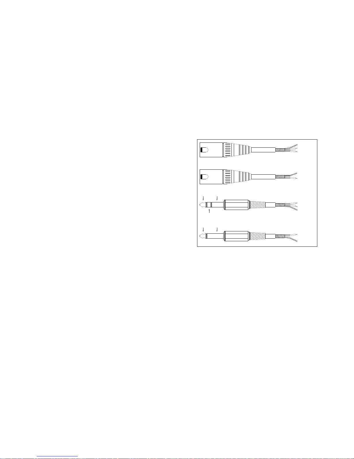
3.5. Input connections
The signal input connections (42, 43, 44, 45, 46, 47) are electronically balanced XLR-3
sockets, with an input impedance higher than 20kΩ and a nominal sensitivity of 0dBV(1V).
Pin assignment:
1. GROUND
2. PHASE (in phase with the output)
3. NON PHASE (inverted phase)
The following diagram shows the connection
of balanced and non-balanced audio sources:
The “STACK OUT” (40, 41) are in parallel with
the inputs and are used to supply the same "IN1 IN2"
input signal to other amplifiers or sound systems. This
signal output connectors are of jack 1/4" type. The pin
assignment is as follows:
HOT or direct signal > Tip
COLD or inverted signal > Ring
GROUND > Body
Some of the connection options for the and the corresponding switch settings are
described later in paragraph 6.2.
Depending on the chosen option, the SP indicators will only light for the active channels.
3.6. Limiter circuit
This system is an always active protection inside the MPA series of amplifiers. The ANTICLIP
circuitry constantly analyses harmonic distortion caused by excessive signal excursion at the power
amplifier's output and automatically reduces the input level in order never to reach distortion.
The great convenience of such a circuit in any kind of installation has to be remarked:
The clear advantage of a limiting system in front of conventional compressors is that the former does
practically not alter the dynamic range, acting only when the distortion threshold is reached.
PHASE GROUND
GROUND
NON PHASE
PHASE
1+3 GROUND
2 PHASE
3 NON PHASE
2 PHASE
1 GROUND
NON PHASE
GROUNDPHASE
PHASE
GROUND
BALANCED
UNBALANCED
BALANCED
UNBALANCED
8
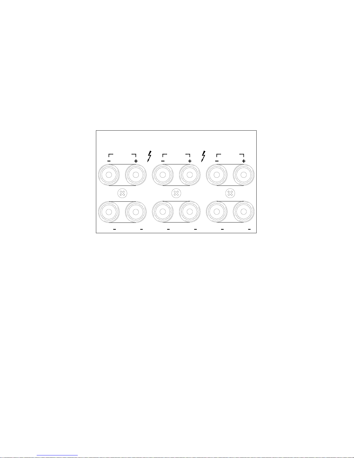
3.7. Output connections
The output section on the rear panel holds 12 screw-type speaker terminals (33, 34, 35,
36, 37, 38), two for each amplifier.
The attenuation controls and the output configurations are described later in paragraph
6.3.
The cable which connects the speakers to the amplifier should be high quality and as short
and thick as possible. This is important when covering long distances; For up to 10m we recommend
a cable section not smaller than 2.5mm². For longer distances we recommend 4mm².
Remember that the minimum load impedance for stereo or mono amplifiers is 4Ω. In
bridged mode the impedance must be not less than 8Ω. For a reliable operation under any
circumstance connect lower load impedances than just specified.
Attention: In bridged mode, use only the red terminals.
4. OPERATION AND USAGE
4.1. Start up
To switch the unit on just push the switch labelled POWER (20) and the integrated
pilot-light will light up. We highly recommend the "safe power-up sequence": First the sound sources,
then mixer, equalizers and active filters and, finally, power amplifiers. Powering off should be done
by following the exact reverse sequence in order to avoid any possible peaks reaching the next
device, and consequently protecting the loudspeakers, which are specially sensitive to these peaks.
CH 6 CH 5 CH 4 CH 3 CH 2 CH 1
MINIMUM LOAD: 4 OHM STEREO, 8 OHM BRIDGE (RED POSTS ONLY)
CH 6 - CH 5 - CH 4 - CH 3 - CH 1 -CH 2 -
OUTPUT
CH 6 + CH 5 +
BRIDGED
CH 4 + CH 3 +
BRIDGED
CH 1 +CH 2 +
BRIDGED
9
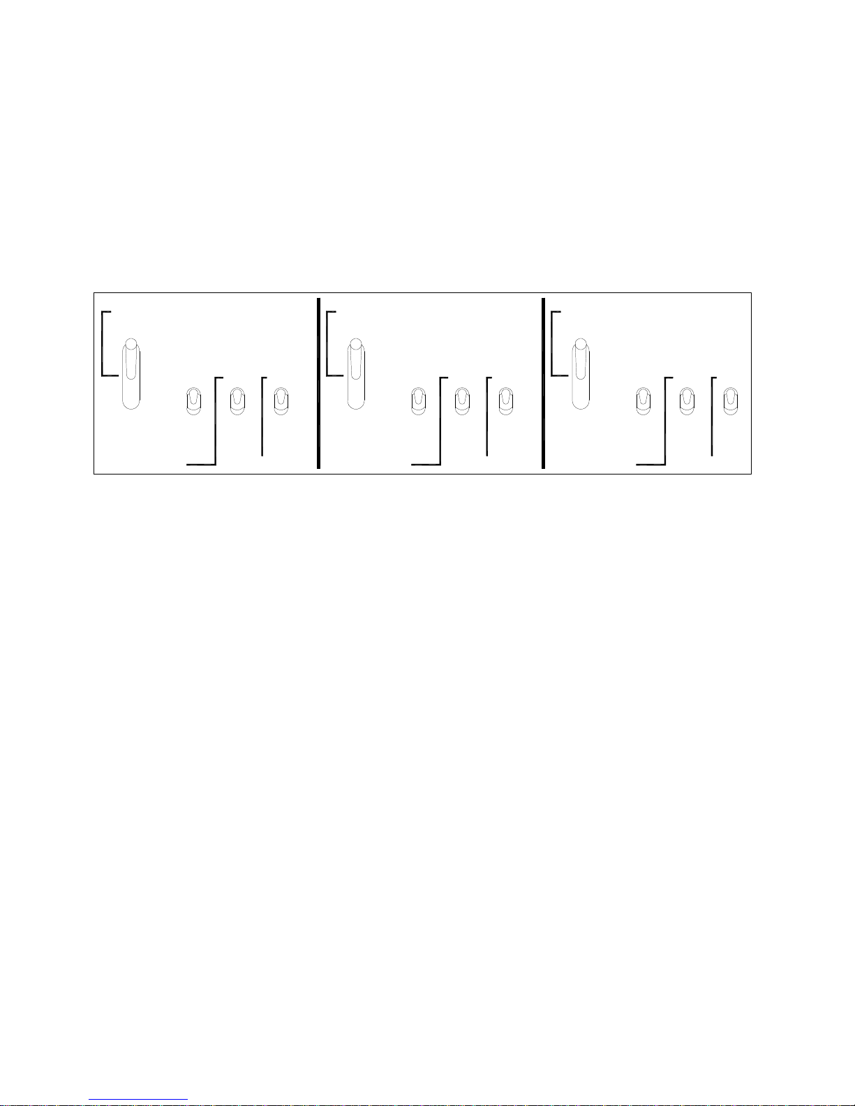
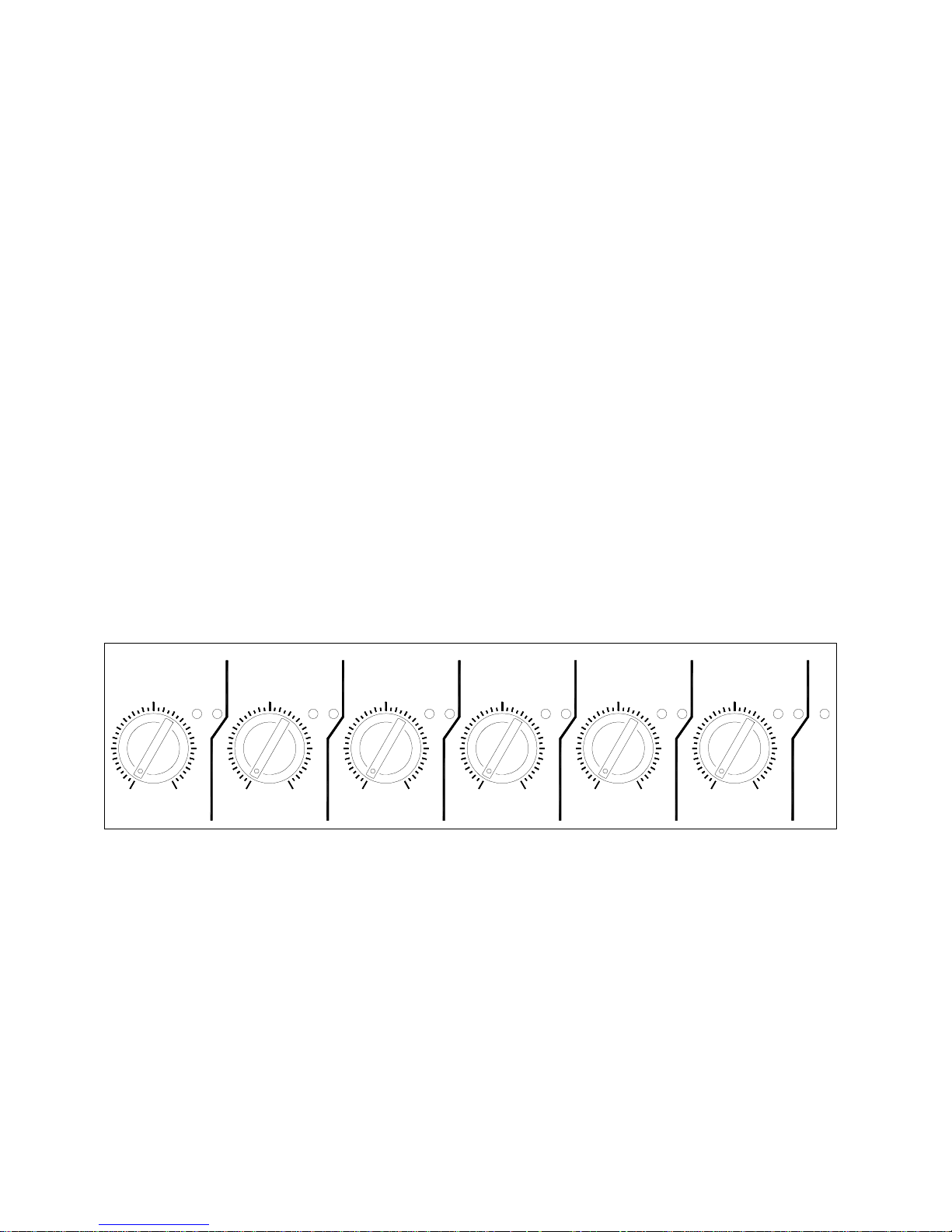
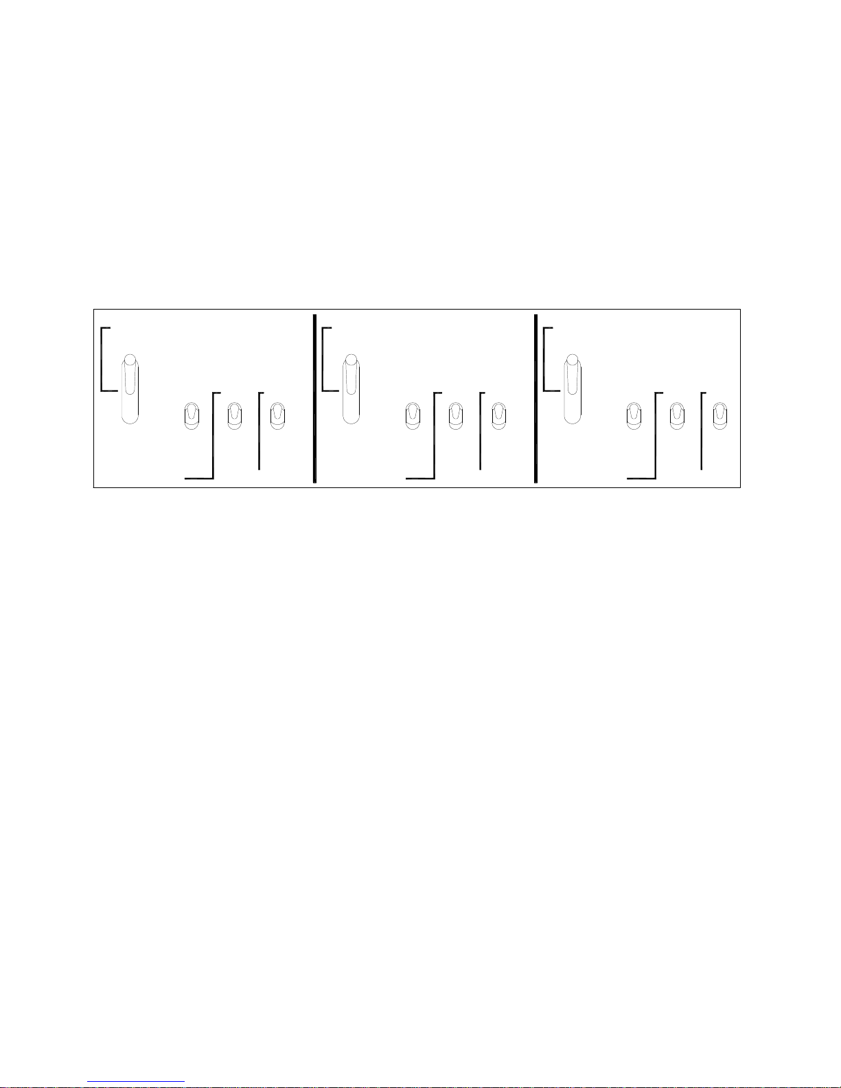
4.2. Input attenuation
These are rotary trimmers located on the front panel (1, 4, 7, 10, 13, 16).
These attenuators allow the connection of different mixers, an independent volume
control and the connection of speakers not able to handle the amplifiers maximum output power, thus
avoiding the risk of damaging them with the mixers or preamps volume control.
Inside the device's packaging you will find a little plastic bag containing 6 transparent caps
which protect the input attenuation settings from unwanted manipulation. These caps are transparent in
order to let you visualize the current settings.
Once inserted, they cannot be removed with bare fingers, for this purpose, a small
screwdriver is needed.
4.3. Indicators
The SP signal presence indicators (2, 5, 8, 11, 14, 17) light up when the input signal
reaches approximately -40dBV.
The CLIP indicators (3, 6, 9, 12, 15, 18) light up when the output signal for the speakers is
-1.5dB below the actual clipping threshold. This clipping system watches for eventual supply voltage
variations, thus giving always an accurate clipping indication, regardless of mains voltage deviations.
It is normal that when operating at high output power, the CLIP indicators light up in
synchronisation with the low frequencies, which carry the most energy. Nevertheless, you should
avoid that the CLIP indicators are lit continuously.
Thermal protection indicator “THERMAL” (19), it shines when the cooling tunnel temperature
reaches 90ºC. The amplifier will automatically restart when the temperature lessens to 80ºC.
5. CLEANING
The front panel should not be cleaned with dissolvent or abrasive substances because silk-
printing could be damaged. To clean it, use a soft cloth slightly wet with water and neutral liquid soap;
dry it with a clean cloth. Be careful that water never gets into the amplifier through the holes of the front
panel.
SP
CHANNEL 3
100 VOL VOL0 10 0 10VOL
CHANNEL 1
5
CLIP
SP
CHANNEL 2
5
SP
CLIP
5
100 VOL VOL0 VOL10 0 10
CHANNEL 5CHANNEL 4
CLIP
5
CLIP
SP
5
CHANNEL 6
CLIP
SP
SP
5
THERMAL
CLIP

10
MANUAL DE INSTRUCCIONES MPA6-150
1. NOTA IMPORTANTE 11
2. INTRODUCCIÓN 11
3. INSTALACIÓN 12
3.1. Ubicación y montaje 12
3.2. Conexión a red 12
3.3. Conmutador “Ground Link” 13
3.4. Multifunción 13
3.5. Conexiones de entrada 14
3.6. Circuito limitador 14
3.7. Conexiones de salida 15
4. OPERACIÓN Y USO 15
4.1. Puesta en funcionamiento 15
4.2. Atenuadores de entrada 16
4.3. Indicadores 16
5. LIMPIEZA 16
6. DIAGRAMAS 34
6.1. Características técnicas 34
6.2. Opciones de entrada 35
6.3. Opciones de salida 37
6.4. Lista de funciones 38
6.5. Diagrama de funciones 40
6.6. Diagrama de bloques 41
Todos los datos están sujetos a variación debida a tolerancias de producción. ECLER S.A. se reserva el derecho
de realizar cambios o mejoras en la fabricación o diseño que pudieran afectar las especificaciones.

11
1. NOTA IMPORTANTE
¡Enhorabuena!. Vd. posee el resultado de un cuidadoso diseño y una esmerada fabricación.
Agradecemos su confianza por haber elegido nuestra etapa de potencia MPA6-150.
Para conseguir la máxima operatividad del aparato y su máximo rendimiento, es MUY
IMPORTANTE antes de su conexión, leer detenidamente y tener muy presentes las consideraciones
que en este manual se especifican.
Para garantizar el óptimo funcionamiento de este aparato, recomendamos que su
mantenimiento sea llevado a cabo por nuestros Servicios Técnicos autorizados.
2. INTRODUCCIÓN
Esta etapa de potencia multicanal ha sido diseñada con la misma tecnología que nuestra
serie de amplificación PAM. Con esta tecnología, ECLER introdujo un nuevo concepto en el audio
profesional: el empleo de los transistores de efecto de campo de conmutación. La tecnología SPM
(Switching Power Mosfet) fue desarrollada y patentada por ECLER S.A. La incorporación al audio de
estos componentes significa una firme y espectacular mejora con relación a los sistemas
convencionales.
Estas ventajas pueden resumirse así:
a) Resistencia interna más baja que los transistores bipolares lo cual redunda en un
calentamiento inferior de la etapa y en unos graves poderosos y muy bien controlados.
Los mosfets convencionales de audio presentan una resistencia interna de 4 a 7 veces
superior a los de conmutación.
b) La enorme rapidez de estos dispositivos confiere a los agudos una transparencia hasta
ahora sólo lograda con amplificadores a válvulas, al tiempo que una TIM (distorsión por
intermodulación de transitorios) muy reducida.
La estación de amplificación MPA6-150 está formada por seis amplificadores de 147W/4Ω
configurables mediante los conmutadores situados en el panel posterior, permitiendo múltiples
posibilidades de trabajo de entre las que destacamos:
6 Amplificadores en mono para 6 señales mono diferentes.
De esta forma el MPA está preparado para trabajar con seis señales distintas disponiendo cada una
de ellas de su propio control de volumen.
6 Amplificadores en mono con una entrada en común.
El amplificador trabaja solamente con una señal de entrada pero conserva la posibilidad de ajustar
de forma independiente el nivel de cada uno de los seis canales, es una aplicación ideal para
realizar una distribución de sonido a distintas zonas.
6 Amplificadores en mono con una entrada en estéreo común.
Aplicación idéntica a la anterior pero teniendo como entrada una fuente de sonido estéreo, el
amplificador realiza la suma de los dos canales de la fuente para convertirla en una señal mono.
3 Amplificadores estéreo con tres entradas estéreo diferentes.
Disponiendo cada una de ellas el control de volumen de cada canal del estéreo. Útil para sonorizar
tres zonas con tres señales estéreo diferentes.
3 Amplificadores estéreo con entrada estéreo común.
Aplicación idéntica a la anterior pero con la misma señal estéreo de entrada en los tres
amplificadores.

12
3 Amplificadores en puente con tres señales mono diferentes.
Podremos disponer de tres zonas con tres señales mono diferentes y con posibilidad de ajustar el
volumen de forma independiente en cada una de ellas. Con un amplificador trabajando en puente
obtendremos el doble de potencia con una impedancia de carga mínima de 8Ω.
3 Amplificadores en puente con una señal mono en común.
El MPA trabaja con una sola señal de entrada para tres amplificadores mono con posibilidad de
controlar los volúmenes de forma independiente.
3 Amplificadores en puente con un entrada estéreo común.
Aplicación idéntica a la anterior pero teniendo como entrada una fuente de sonido estéreo, el
amplificador realiza la suma de los dos canales de la fuente para convertirla en una señal mono.
4 Amplificadores mono y 1 amplificador en puente con una entrada mono común.
Útil para instalaciones donde se necesiten 4 amplificadores de una potencia determinada (para
cajas de medios y agudos) y un amplificador en puente con más potencia de salida (para caja de
subgraves. Este amplificador multicanal dispone de filtro paso bajo para instalar cajón de subgraves
y de filtros paso alto para las cajas de medios y agudos.
3. INSTALACIÓN
3.1. Ubicación y montaje
El amplificador se presenta en módulo rack de 19" y dos unidades de altura, se suministra
con arandelas de plástico con el fin de poderlo montar en un rack sin dañar el aparato.
Es muy importante que, como elemento generador de calor que es, el amplificador no esté
completamente encerrado ni expuesto a temperaturas extremas.
3.2. Conexión a red
El amplificador se alimenta con corriente alterna, según el país, de 110-120, 220-240V
50/60Hz. (ver placa de características en el aparato), su consumo a plena potencia es de 1650VA, por
ello es importante que la instalación de red sea la adecuada a tal consumo.
La etapa debe conectarse a una toma de tierra en condiciones (Resistencia de tierra,
Rg=30Ω o menos). El ambiente de trabajo deberá ser seco y estar totalmente libre de polvo. No
exponga el aparato a la caída de agua o salpicaduras, no ponga encima objetos con líquido ni
fuentes de llama desnuda, como velas. No obstruya los orificios de ventilación con ningún tipo de
material. En caso de requerir alguna intervención y/o conexión-desconexión del amplificador debe
desconectarse previamente la alimentación. En el interior del amplificador no existen elementos
manipulables por el usuario.
Debe evitarse que el cable de red se entremezcle con los cables blindados que transportan
la señal de audio, ya que ello podría ocasionar zumbidos.
Para proteger al amplificador de eventuales sobrecargas en la línea de red o bien excesos
ocasionales en el consumo de los circuitos internos, está provisto de un fusible de red T 16A
*. En caso de que éste se fundiera se desconectaría el aparato y se sustituiría por otro de
idénticas características. Si éste último se volviera a fundir, consulte con nuestro Servicio
Técnico. EN NINGÚN CASO DEBE PONERSE UN FUSIBLE DE VALOR MÁS ELEVADO.
* En la MPA6-150 el fusible es interno y debe ser manipulado por personal técnico cualificado.
13
3.3. Conmutador Ground Link
El conmutador “GND LINK” (48) tiene por misión evitar la creación de bucles de masa,
originados cuando se conectan a tierra varios aparatos integrantes de una misma cadena de forma
simultánea. Este conmutador permite la desconexión de la masa eléctrica del circuito de la masa del
chasis. En caso de producirse zumbidos actuar alternativamente sobre el conmutador del amplificador
y demás elementos de la cadena de audio.
3.4. Multifunción
En el MPA6-150 según la posición de los conmutadores de entrada
(21, 22, 23, 24, 25, 26, 27, 28, 29, 30, 31, 32) situados en el panel posterior dispondremos de 4
funciones diferentes de amplificación:
- Seis amplificadores en mono, con posibilidad de:
Seis entradas en mono distintas.
Una misma entrada en mono para todos.
Una señal en estéreo común para todos.
- Tres amplificadores en estéreo, con posibilidad de:
Tres entradas en estéreo diferentes.
Una sola entrada en estéreo común para los tres.
- Tres amplificadores en puente, con posibilidad de:
Tres entradas en mono diferentes.
Una entrada en mono en común
Una entrada en estéreo común.
- Combinación entre amplificadores mono, estéreo y puente.
También en este panel posterior podremos activar el funcionamiento de los filtros pasa-altos
y pasa-bajos:
On/Off del filtro pasa-altos (27 (31)). Filtro con frecuencia de corte en 160Hz para los
amplificadores 3 y 4 (5 y 6) a la vez o cuando estos trabajan en modo puente. Este filtro elimina la
señal de audio de frecuencias inferiores a 160Hz y deja pasar las superiores, por ello este filtro es ideal
para conectar en estos amplificadores cajas de medios y agudos.
On/Off del filtro pasa-bajos (23). Este interruptor activa el funcionamiento de un filtro del
amplificador 1 que elimina la señal de audio de frecuencias superiores a los 160Hz y deja pasar las
inferiores a ésta.
CHANNEL 3
HP FILTER
ON
OFF
BRIDGE
IN 5+IN 6
CHANNEL 6
STEREO
BRIDGE IN 5
IN 3+IN 4
BRIDGELINKLINK
CHANNEL 5
CH 4 CH 3
IN 6 IN 5
ON LINK
CHANNEL 4
CH 2
OFF
HP FILTER
IN 4
STEREO
BRIDGE IN 3
CHANNEL 2
LP FILTER
LINK BRIDGE
IN 1+IN 2CH 1
IN 3
LINKON IN 1+
CHANNEL 1
CH 1 IN 2
IN 2OFF IN 1
BRIDGE IN 1
STEREO
 Loading...