

Page 1

USER MANUAL
MANUAL DE INSTRUCCIONES
MIMO88SG
Page 2
2
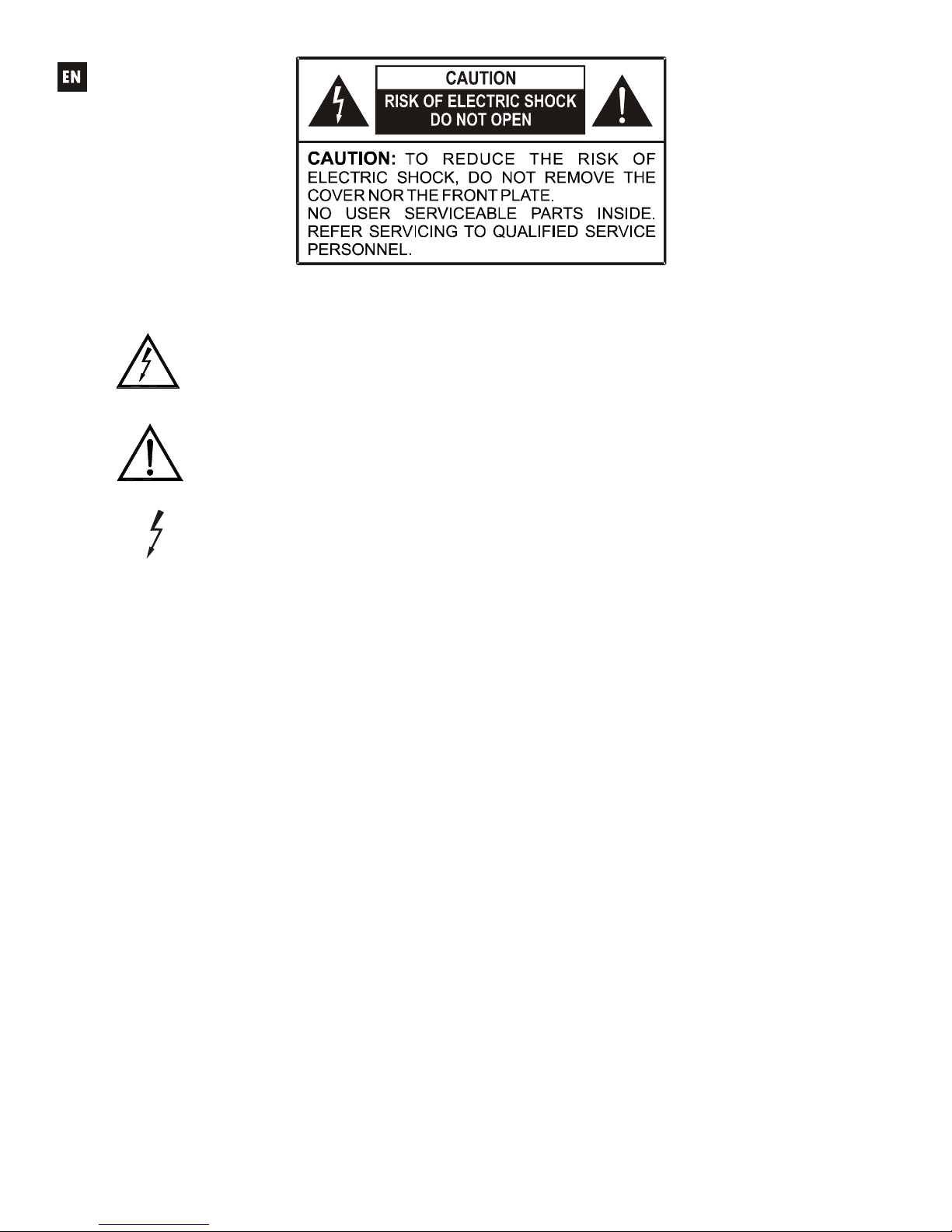
Graphic Symbol Explanation
The lightning flash with arrowhead symbol, within an equilateral triangle, is intended to
alert the user to the presence of uninsulated “dangerous voltage” within the product’s
enclosure that may be of sufficient magnitude to constitute a risk of electric shock to
persons.
The exclamation point within an equilateral triangle is intended to alert the user to the
presence of important operating and maintenance (servicing) instructions in the literature
accompanying the appliance.
The lightning flashes printed next to the OUTPUT terminals of the amplifier are intended
to alert the user to the risk of hazardous energy. Output connectors that could pose a risk
are marked with the lightning flash. Do not touch output terminals while amplifier power is
on. Make all connections with amplifier turned off.
WARNING: To prevent fire or shock hazard, do not expose this equipment to rain or moisture.
IMPORTANT SAFETY INSTRUCTIONS
1. Read these instructions.
2. Keep these instructions.
3. Heed all warnings.
4. Follow all instructions.
5. Do not use this apparatus near water.
6. Clean only with dry cloth.
7. Do not block any ventilation openings. Install in accordance with the manufacturer’s instructions.
8.
Do not install near any heat sources such as radiators, heat registers, stoves, or other apparatus
(including amplifiers) that produce heat.
9. Do not defeat the safety purpose of
the polarized or grounding type plug. A polarized plug has
two blades with one wider than the other. A grounding type plug has two blades
and a
third
grounding
prong. The
wide blade or the third prong are provided for your safety. If the provided
plug does not fit into your outlet, consult an electrician for replacement of the obsolete outlet.
10.
Protect the power cord from being
walked on or pinched particularly at the plugs, convenience
receptacles, and at the point where they exit from the apparatus.
11. Only use attachments/accessories specified by the manufacturer.
12. Unplug the apparatus during lightening sorts or when unused for long periods of time.
13.
Refer all servicing to qualified personnel. Servicing is required when the apparatus has been
damaged in any way, such as power supply cord or plug is
damaged, liquid has been spilled
or
objects have fallen into the apparatus, the apparatus has been exposed to rain or moisture, does
not operate normally, or has been dropped.
14. Disconnecting from mains: Switching off the POWER switch (13) all the functions and light
indicators of the amplifier will be stopped, but fully disconnecting the device from mains is done
unplugging the power cord from the mains input socket (11). For this reason, it always shall
remain readily operable.
Page 3

3
LIST OF CONTENTS
1. IMPORTANT REMARK 04
1.1. Safety Precautions 04
2. INTRODUCTION 04
3. INSTALLATION 05
3.1. Location, assembly, ventilation 05
3.2. Connection to an AC outlet and switching on 05
3.3. Signal input connections 05
3.4. Audio Output Connections 05
3.5. ETHERNET port for programming and control 06
3.6. REMOTE port for digital remote controls 06
3.7. GPI Remote Control Ports 07
3.8. Remote control RS-232 Port 07
3.9. Front panel controls and LED indicators 08
4. CLEANING 08
5. FUNCTION LIST 09
6. FUNCTION DIAGRAM 09
7. TECHNICAL CHARACTERISTICS 34
8. BLOCK DIAGRAM 38
All numbers subject to variation due to production tolerances. ECLER S.A. reserves the right to make changes or
improvements in manufacturing or design which may affect specifications.
Page 4

4
1. IMPORTANT REMARK
Thank you for your confidence and for choosing our MIMO88SG matrix. It is VERY IMPORTANT to
carefully read this manual, to fully understand its contents before any connection in order to maximize your use and
get the best performance from this equipment.
In order to guarantee the optimum operation of this unit, we strongly recommend that its maintenance be
carried out by our Authorized Technical Services.
The MIMO88SG come with a 3-year warranty.
1.1. Safety Precautions
This apparatus must be earthed through its mains cable.
Do not expose the unit to rain or water splashes, and do not place liquid containers or
incandescent objects like candles on top of the unit.
Should any connection / disconnection task be done, always disconnect the unit from the mains supply.
There are no user serviceable parts inside the unit.
2. INTRODUCTION
The MIMO88SG is a fully programmable digital audio matrix, with the following features:
8 balanced MIC/LINE inputs (independent phantom power per input channel).
8 balanced LINE outputs.
8 GPI control ports (General Purpose Input).
Programming and remote management via Ethernet using EclerNet Manager (or point to point,
with a direct CAT5 cable, or from an Ethernet network).
Remote control via UCP (User Control Panel) clients on Ethernet: simultaneous clients with
customized control panel, such as WPmSCREEN Ecler, Android®, iOS®, Windows®, etc.
Remote control from third party external devices. (Crestron, AMX, Vity, Medialon, etc. Registered
trademarks of their manufacturers). TP-NET protocol, via Ethernet or RS-232 ports.
Remote control bus for WPTOUCH digital panels and MPAGE16 messaging consoles (paging).
Configuration memory (presets) management.
Scheduled events based on calendar.
Extensive DSP available:
o Routing matrix/mixer, from any input to any output with adjustable level for crossover
points (independent mixes of different inputs for each output).
o Mono or stereo channel processing.
o Level control, mute, vu-meters and phase adjustment for inputs and outputs.
o Internal signal generator (sine wave, pink noise, white noise, polarity test).
o Parametric EQ on inputs and outputs.
o Delay on inputs and outputs.
o Gate/compressor on input channels.
o Compressor/limiter on outputs.
o Input channel priority assignment (ducking).
o Virtual and physical messaging consoles (paging).
o Standard MIMO88SG firmware version (for generic use) and alternative version, for
conferencing applications (MIMO88SG CONFERENCE version). Both firmware versions
are compatible with the MIMO88SG hardware which can be freely updated with anyone of
them.
The MIMO88SG programming is done with EclerNet Manager*. Please refer to the EclerNet Manager
software manual for more information.
* EclerNet Manager software is available on www.ecler.com.
Page 5
5
3. INSTALLATION
3.1. Location, assembly, ventilation
The MIMO88SG has been especially designed to be installed in a standard 19" rack, taking up 1U.
It is very important not to enclose the MIMO88SG or expose it to extreme temperatures as it generates
heat. It’s also necessary to promote the passage of fresh air through the ventilation holes of the chassis, leaving at
least one rack unit off between each device and installed above and below it in the rack frame.
If the setup has several amplifiers in the same rack or in a closed cabinet with doors, it is highly
recommended to supply them forced ventilation, installing fans at the upper and lower ends. This upward air flow
will help to dissipate the heat generated inside.
3.2. Connection to an AC outlet and switching on
The MIMO88SG operates under voltages between 90 and 264 V at 47 to 63 Hz. This device features an
over dimensioned power supply that adapts to the mains voltage in any country of the world with no need to make
any adjustments.
On the rear panel, there is a power switch for the unit (13) next to the IEC power connector. On the front
panel, a LED (4) lights up when the unit is switched on.
The mains cables must not be near the shielded cables carrying the audio signal, as this could cause
humming.
3.3. Signal input connections
The rear panel of the MIMO88SG offers 8 balanced analogue signal inputs, "IN" (6), accepting both line
and microphone level signals. Input signal type selection and management are carried out from EclerNet Manager
application. Please refer to the EclerNet Manager software manual for more information.
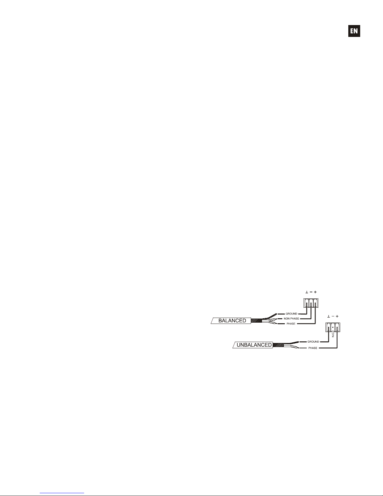
Signal input connectors are 3 position screw terminal block. The wiring is:
Hot or direct signal > Terminal +
Cold or inverted signal > Terminal Ground > Terminal
For unbalanced connection short-circuit pin to pin -.
3.4. Audio Output Connections
The rear panel of the MIMO88SG offers 8 analogue signal outputs "OUT" (5), all balanced and accepting
line level signals.
Signal output connectors are 3 position screw terminal
block. The wiring is:
Hot or direct signal > Terminal +
Cold or inverted signal > Terminal Ground > Terminal
For UNBALANCED connections, leave the – terminal
unconnected.
Page 6

6
3.5. ETHERNET port for programming and control
A RJ45 type connector (7) allows connecting the equipment to an Ethernet network:
Management from EclerNet Manager application. Please refer to the EclerNet Manager software manual
for more information.
Possibility of direct connection (point to point) between a computer and a MIMO88SG unit.
Connection to third party other devices. (Crestron, AMX, Vity, Medialon, etc. Registered trademarks of their
manufacturers). Protocol used: Ecler TP-NET. See the TP-NET protocol manual for more information.
Connection to WPmSCREEN units (remote control of an entire network of EclerNet devices through
custom graphic panels).
3.6. REMOTE port for digital remote controls
The REMOTE port allows the connection of digital remote control devices, such as the
WPTOUCH wall panel or the MPAGE16 paging console. The REMOTE port is connected to the
digital control bus the remote devices are daisy-chained to, the last one being loaded with a
120 termination resistor between CAN HIGH and CAN LOW.
Refer to the remote device documentation (WPTOUCH, MPAGE16, etc) for more
information about your connection and controls.
Please refer to the EclerNet Manager software manual for more information about programming the
MIMO88SG to manage the remote devices that are connected to the REMOTE port.
Page 7
7
3.7. GPI Remote Control Ports
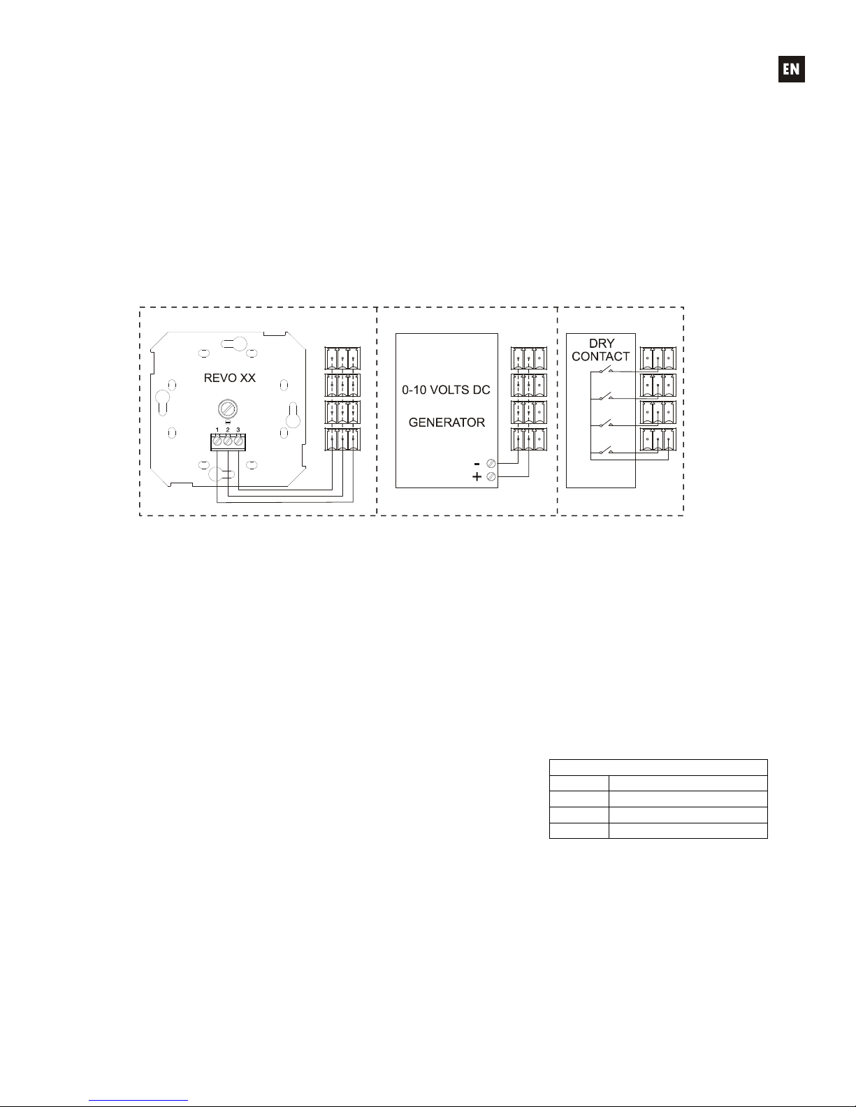
The rear panel of the MIMO88SG offers 8 GPI inputs (10) for 0-10 VDC continuous control voltage. Each
of these inputs can be connected to an external physical device (potentiometer, contact closure, continuously
variable voltage 0-10V DC, etc.) and assigned to a MIMO88SG function, as for example:
Input, output channel or matrix crosspoint volume remote control by means of a WPVOL physical
knob or an Ecler WP Series WPVOL-IR remote control
MUTE or SOLO activation/deactivation by means of a switch or contact closure
Recalling a preset with a push button or contact closure
GPI connectors are screw terminal blocks with three-contacts. The wiring is as follows:
Positive, + 10 VDC > Pin +
Variable voltage, 0-10 VDC > Pin
Ground > Pin
Examples of connection
Connecting cables can be up to 500 meters with a minimum section of 0.5 mm
2
.
Consult your ECLER dealer or www.ecler.com about the WP series remote control wall panels and other
accessories available for connection to the REMOTE/VCA port.
3.8. Remote control RS-232 Port
The built-in RS-232 port in the rear panel allows an external device to communicate with an MIMO88SG
unit via a serial connection. Said connection uses the TP-NET protocol syntax so to enable the external device to
obtain the value of any of the parameters of the MIM088 unit (by "GET" commands) and/or modify said values
(“SET” commands). See the TP-NET protocol manual for more information.
The serial connection should comply with the following specifications:
Baud rate: 57600 (fixed, no auto negotiation)
Data bits: 8
Parity: None
Stop bits: 1
Flow control: None
WIRING RS232 – DB9
RS232 DB9
Tx Pin 2 (RxD)
Rx Pin 3 (TxD)
Gnd Pin 5 (Signal Gnd)
Page 8

8
3.9. Front panel controls and LED indicators
The following elements are available on the MIMO88SG front panel:
Input LED indicators (1): indicate the presence of audio signal at the unit’s input, and its intensity level
(green, amber and red indicate in this order the increased intensity level)
Output LED indicators (2): indicate the presence of audio signal at the unit’s output, and its intensity level
(green, amber and red indicate in this order the increased intensity level)
Status LED indicators (STATUS):
o DATA: (3) Off: there is no connection to EclerNet Manager even if connected to Ethernet. On:
connected to EclerNet Manager or to other third party application via TP-NET protocol. Flashing:
data traffic with EclerNet Manager or another application.
o POWER: (4) illuminates when the unit is in operation. It flashes if there is an error in the unit or if
firmware is not correct. It also flashes when you update firmware
4. CLEANING
The front panel should not be cleaned with dissolvent or abrasive substances because silk-printing could
be damaged. To clean it, use a soft cloth slightly wet with water and neutral liquid soap; dry it with a clean cloth. Be
careful that water never gets into the unit through the holes of the front panel.
Page 9

9
5. FUNCTION LIST
1. Input signal indicators, INPUTS
2. Output signal indicators, OUTPUTS
3. Data traffic indicator, DATA
4. Power on indicator, POWER
5. Signal output screw terminal, OUT
6. Signal input screw terminal, IN
7. RJ-45 connector, ETHERNET
8. Screw terminals for digital remote control, REMOTE
9. Screw-assembled remote control terminals via the TP-NET, RS-232 protocol
10. Screw terminals for continuous voltage control, GPI
11. Mains socket
12. Fuse holder
13. Power switch
6. FUNCTION DIAGRAM
1
1
5
6
7
8
9
11123
2
3
4
0
1
Page 10

10
Explicación de los Símbolos Gráficos
El símbolo del relámpago con una flecha en la punta y dentro de un triangulo equilátero,
tiene el propósito de alertar al usuario de la presencia de un voltaje peligroso y sin aislar
dentro del aparato, y de una magnitud tal que puede constituir riesgo de descarga
eléctrica para las personas.
El símbolo de exclamación dentro de un triangulo equilátero, tiene el propósito de alertar
al usuario de la presencia de instrucciones importantes sobre la operación y
mantenimiento en la información que viene con el producto.
Los símbolos de relámpagos dibujados cerca de los terminales de salida se utilizan para
alertar al usuario del riesgo de descargas peligrosas. Los conectores de salida que
podrían plantear algún riesgo se indican con este símbolo del relámpago. No toque los
terminales de salida mientras que el amplificador esté encendido. Hacer todas las
conexiones con el amplificador apagado.
ADVERTENCIA: para prevenir choques eléctricos o riesgo de incendios, no exponer este equipo a la
lluvia o la humedad.
INSTRUCCIONES IMPORTANTES DE SEGURIDAD
1. Lea estas instrucciones
2. Guarde estas instrucciones
3. Preste atención a todas las advertencias
4. Siga todas las instrucciones
5. No utilice este aparato cerca del agua
6. Límpielo solamente con un paño seco
7. No bloquee ninguna abertura para ventilación. Instálelo de acuerdo con las instrucciones del
fabricante
8. No lo instale cerca de fuentes de calor como radiadores, estufas u otros aparatos que produzcan
calor, incluidos amplificadores.
9. No elimine el propósito de seguridad del cable de corriente polarizado o con conexión de tierra.
Un cable polarizado tiene dos bornes, uno más ancho que el otro. Un enchufe con conexión a
tierra, tiene dos bornes y un tercer borne conectado a tierra. Este tercer borne está previsto para
su seguridad. Si el cable proporcionado no entra en su enchufe, consulte con un técnico
electricista para reemplazar ese enchufe obsoleto.
10. Proteja el cable eléctrico de ser aplastado, en especial en la zona de los conectores, los
receptáculos de los mismos y en el punto en el que el cable sale del aparato.
11. Utilice solamente los accesorios especificados por el fabricante.
12. Desconecte el aparato durante las tormentas eléctricas o cuando no lo vaya a usar durante
periodos largos de tiempo.
13. Para cualquier reparación, póngase en contacto con un servicio técnico cualificado. La
reparación es necesaria cuando el aparato no funciona con normalidad o ha sido dañado por
cualquier motivo, ya sea porque el cable o el enchufe estén dañados, porque se hayan
derramado líquidos o hayan caído objetos dentro del aparato, o porque el aparato haya sido
expuesto a la lluvia o se haya caído.
14. Desconexión de la red: apagando el interruptor de POWER (13) todas las funciones e
indicadores del amplificador se pararán, pero la completa desconexión del aparato se consigue
desconectando el cable de red de su conector (11). Por esta razón, éste siempre debe tener fácil
acceso.
Page 11

11
ÍNDICE
1. NOTA IMPORTANTE 12
1.1. Precauciones 12
2. INTRODUCCIÓN 12
3. INSTALACIÓN 13
3.1. Ubicación, montaje, ventilación 13
3.2. Conexión a red eléctrica y encendido 13
3.3. Conexiones de entrada de señal 13
3.4. Conexiones de audio de salida 13
3.5. Puerto ETHERNET de programación y control 14
3.6. Puerto REMOTE para controles remotos digitales 14
3.7. Puertos GPI de control remoto 15
3.8. Puerto RS-232 de control remoto 15
3.9. Controles e indicadores LED del panel frontal 16
4. LIMPIEZA 16
5. LISTA DE FUNCIONES 17
6. DIAGRAMA DE FUNCIONAMIENTO 17
7. CARACTERÍSTICAS TÉCNICAS 34
8. DIAGRAMA DE BLOQUES 38
Todos los datos están sujetos a variación debida a tolerancias de producción. ECLER S.A. se reserva el derecho de realizar
cambios o mejoras en la fabricación o diseño que pudieran afectar las especificaciones.
Page 12

12
1. NOTA IMPORTANTE
Agradecemos su confianza por haber elegido nuestra matriz MIMO88SG. Para conseguir la máxima
operatividad y rendimiento de su equipo es MUY IMPORTANTE, antes de su conexión, leer detenidamente y tener
muy presentes las consideraciones que en este manual se especifican.
Para garantizar el óptimo funcionamiento de este aparato recomendamos que su mantenimiento sea
llevado a cabo por nuestros Servicios Técnicos autorizados.
El MIMO88SG tiene una garantía de 3 años.
1.1. Precauciones
Este aparato debe ser conectado a tierra mediante su cable de alimentación.
No exponga el aparato a la caída de agua o salpicaduras, no ponga encima objetos con líquido ni fuentes
de llama desnuda, como velas.
En caso de requerir alguna intervención y/o conexión desconexión del aparato debe desconectarse
previamente de la alimentación.
En el interior del aparato no existen elementos manipulables por el usuario.
2. INTRODUCCIÓN
MIMO88SG es una matriz digital de audio, totalmente programable y con las siguientes características
principales:
8 entradas MICRO/LÍNEA simétricas (alimentación Phantom independiente por canal de entrada).
8 salidas de LÍNEA simétricas.
8 puertos de control GPI (General Purpose Input).
Programación y gestión remota vía Ethernet mediante aplicación EclerNet Manager (bien punto a
punto, con cable CAT5 directo, bien desde un puesto de red Ethernet).
Control remoto mediante clientes Ethernet de EclerNet Manager: clientes simultáneos con panel
de control personalizado.
Control remoto mediante clientes UCP (User Control Panels) vía Ethernet: clientes simultáneos
con panel de control personalizado, tipo Ecler WPmSCREEN, Android®, iOS®, Windows®, etc..
Bus de control remoto para paneles digitales WPTOUCH y consolas de mensajes (paging)
MPAGE16.
Gestión de memorias de configuración (presets).
Eventos programados en base a calendario.
Amplio procesamiento DSP disponible:
o Matriz enrutadora-mezcladora, desde cualquier entrada hacia cualquier salida con nivel de
puntos de cruce ajustable (mezclas independientes de diferentes entradas para cada
salida).
o Tratamiento de canales en modo mono o estéreo.
o Nivel, enmudecimiento, vu-metros y ajuste de fase en entradas y salidas.
o Generador de señal interno (señal senoidal, ruido rosa, ruido blanco, test de polaridad).
o EQ paramétrica en entradas y en salidas.
o Retardos en entradas y en salidas.
o Puerta de ruido / compresor en canales de entrada.
o Compresor / limitador en salidas.
o Prioridades (ducking) entre canales de entrada.
o Consolas de mensajes (paging) virtuales y físicas.
o Versión de firmware estándar MIMO88SG (de uso genérico) y alternativa, para
aplicaciones de conferencia (versión MIMO88SG CONFERENCE). Ambas versiones de
firmware son compatibles con el hardware MIMO88SG, pudiendo actualizar dicho
hardware con una u otra libremente
La programación del MIMO88SG se realiza mediante la aplicación EclerNet Manager*. Consulte el manual
de la Aplicación EclerNet Manager para obtener más información.
* La aplicación EclerNet Manager se encuentra disponible para su descarga en www.ecler.com.
Page 13

13
3. INSTALACIÓN
3.1. Ubicación, montaje, ventilación
MIMO88SG ha sido especialmente diseñado para su ubicación en muebles rack de 19", ocupando una
unidad de altura.
Es muy importante que, como elemento generador de calor que es, el MIMO88SG no esté completamente
encerrado ni expuesto a temperaturas extremas. Debe favorecerse el paso de aire fresco a través de los orificios
de ventilación del chasis, dejando al menos una unidad de rack libre entre cada equipo y los instalados encima y
debajo de él en el bastidor de rack.
Si la instalación consta de varios amplificadores en el mismo rack o se realiza dentro de armarios cerrados
mediante puertas, es altamente recomendable dotar a éstos de ventilación forzada ascendente, instalando
ventiladores en sus extremos inferior y superior. Dicho flujo ascendente de ventilación favorecerá la disipación del
calor generado en su interior.
3.2. Conexión a red eléctrica y encendido
El MIMO88SG funciona con tensión alterna de 90 a 264V y 47 a 63Hz. Este aparato equipa una fuente de
alimentación sobredimensionada capaz de adaptarse sin ningún tipo de ajuste a la tensión de red de cualquier
país del mundo.
En el panel posterior, y junto al conector IEC de alimentación, existe un interruptor de encendido /
apagado de la unidad (13). En el panel frontal existe un indicador LED (4) que se ilumina cuando al unidad se
encuentra en funcionamiento.
Debe evitarse que el cable de red se entremezcle y discurra paralelo a los cables blindados que
transportan la señal de audio, ya que ello podría ocasionar zumbidos.
3.3. Conexiones de entrada de señal
MIMO88SG dispone en su panel posterior de 8 entradas analógicas de señal "IN" (6), simétricas y que
admiten niveles de línea o micrófono. La selección del tipo de señal de entrada y su gestión se realiza desde la
aplicación EclerNet Manager. Consulte el manual de la aplicación EclerNet Manager para obtener más
información.
Los conectores de entrada de señal son del tipo de regleta de tornillos de tres contactos. La asignación del
conexionado es la siguiente:
Vivo o señal directa > Terminal +
Frío o señal invertida > Terminal Masa > Terminal
Para conexiones NO balanceadas cortocircuitar a masa el terminal -.
3.4. Conexiones de audio de salida
MIMO88SG dispone en su panel posterior de 8 salidas analógicas de señal "OUT" (5), simétricas y con
nivel de línea.
Los conectores de salida de señal son del tipo de
regleta de tornillos de tres contactos. La asignación del
conexionado es la siguiente:
Vivo o señal directa > Terminal +
Frío o señal invertida > Terminal Masa > Terminal
Para conexiones NO balanceadas dejar sin conectar
el terminal -.
Page 14

14
3.5. Puerto ETHERNET de programación y control
Un conector tipo RJ45 (7) permite la conexión del equipo a una red Ethernet:
Gestión desde la aplicación EclerNet Manager. Consulte el manual de la Aplicación EclerNet Manager
para obtener más información.
Posibilidad de conexión directa (punto a punto) de un ordenador con una unidad MIMO88SG.
Conexión a otros aparatos de terceros. (Crestron, AMX, Vity, Medialon, etc. Marcas registradas por sus
fabricantes). Protocolo empleado: Ecler TP-NET. Consulte el manual del protocolo TP-NET para más
información.
Conexión a unidades WPmSCREEN (control remoto de toda una red de dispositivos EclerNet mediante
paneles gráficos hechos a medida)
3.6. Puerto REMOTE para controles remotos digitales
El puerto REMOTE permite la conexión de de dispositivos digitales de control remoto,
como el panel mural WPTOUCH o la consola de mensajes (paging) MPAGE16. Al puerto
REMOTE se conectará el bus de control digital, en el cual los dispositivos remotos se hallarán
encadenados (daisy-chain) y el último de ellos cargado con una resistencia terminal de 120
entre CAN HIGH y CAN LOW.
Consulte la documentación del dispositivo remoto (WPTOUCH, MPAGE16, etc.) para
más información acerca de su conexionado y controles.
Consulte el manual de la Aplicación EclerNet Manager para obtener más información acerca de la
programación de MIMO88SG para gestionar los dispositivos remotos conectados al puerto REMOTE.
Page 15

15
3.7. Puertos GPI de control remoto
MIMO88SG dispone en su panel posterior de 8 entradas GPI (10) de control por tensión continua, 0 a 10
VDC. Cada una de estas entradas puede conectarse a un dispositivo físico externo (un potenciómetro, un cierre
de contacto, una tensión continua 0-10V variable, etc.) y asociarse a una función del MIMO88SG, como por
ejemplo:
Control remoto de un volumen de canal de entrada, salida o punto de cruce de la matriz mediante
un potenciómetro físico WPVOL o un control remoto WPVOL-IR de la serie WP de Ecler
Activación / desactivación de un MUTE o SOLO mediante un pulsador o cierre de contacto
Recuperación de un preset mediante un pulsador o cierre de contacto
Los conectores GPI son del tipo de regleta de tornillos de tres contactos. La asignación del conexionado
es la siguiente:
Positivo, + 10 VDC > Terminal +
Tensión variable, 0-10 VDC > Terminal
Masa > Terminal
Algunos ejemplos de conexionado
Los cables de conexión pueden ser de hasta 500 metros aproximadamente, utilizando una sección mínima
de 0,5 mm
2
.
Consulte a su distribuidor ECLER o bien en www.ecler.com acerca de los paneles murales de control
remoto serie WP y otros accesorios disponibles para la conexión a puertos REMOTE / VCA.
3.8. Puerto RS-232 de control remoto
El puerto RS-232 integrado en el panel posterior permite que un dispositivo externo se comunique con una
unidad MIMO88SG mediante conexión serie. Dicha conexión empleará la sintaxis del protocolo TP-NET para que
el dispositivo externo pueda obtener el valor de alguno de los parámetros de la unidad MIMO88SG (mediante
comandos “GET”) y/o modifique dichos valores (comandos “SET”). Consulte el manual del protocolo TP-NET para
más información.
La conexión serie debe cumplir con las siguientes características:
Baud rate: 57600 (fixed, no auto negotiation)
Data bits: 8
Parity: None
Stop bits: 1
Flow control: None
CABLEADO RS232 – DB9
RS232 DB9
Tx Terminal 2 (RxD)
Rx Terminal 3 (TxD)
Gnd Terminal 5 (Signal Gnd)
Page 16

16
3.9. Controles e indicadores LED del panel frontal
MIMO88SG dispone en su panel frontal de los siguientes elementos:
Indicadores LED de entradas (1): muestran la presencia de señal de audio en las entradas de la unidad, y
su nivel de intensidad (colores verde, ámbar y rojo, que corresponden por este orden a un nivel creciente
de intensidad)
Indicadores LED de salidas (2): muestran la presencia de señal de audio en las salidas de la unidad, y su
nivel de intensidad (colores verde, ámbar y rojo, que corresponden por este orden a un nivel creciente de
intensidad)
Indicadores LED de estado (STATUS):
o DATA: (3) Apagado, no existe conexión con el EclerNet Manager aunque esté conectado a
ETHERNET. Encendido, conectado al EclerNet Manager o conectado a la aplicación de terceros
mediante el protocolo TP-NET. Parpadea, tráfico de datos con el EclerNet Manager u otros.
o POWER: (4) se ilumina cuando la unidad se halla en funcionamiento. Si parpadea hay error en la
unidad o el firmware no es correcto. También parpadea al actualizar el firmware
4. LIMPIEZA
La carátula no deberá limpiarse con sustancias disolventes o abrasivas puesto que se corre el riesgo de
deteriorar la serigrafía. Para su limpieza se utilizará un trapo humedecido con agua y un detergente líquido neutro,
secándola a continuación con un paño limpio. En ningún caso se debe permitir la entrada de agua por cualquiera
de los orificios del aparato.
Page 17

17
5. LISTA DE FUNCIONES
1. Indicadores luminosos de señal de entrada, INPUTS
2. Indicadores luminosos de señal de salida, OUTPUTS
3. Indicador luminoso de tráfico de datos, DATA
4. Indicador luminoso de puesta en marcha, POWER
5. Terminales atornillables salida de señal, OUT
6. Terminales atornillables entrada de señal, IN
7. Conector RJ-45, ETHERNET
8. Terminales atornillables de control remoto digital, REMOTE
9. Terminales atornillables de control remoto mediante protocolo TP-NET, RS-232
10. Terminales atornillables de control por tensión continua, GPI
11. Base de toma de red
12. Portafusible
13. Interruptor de puesta en marcha
6. DIAGRAMA DE FUNCIONAMIENTO
1
1
5
6
7
8
9
11123
2
3
4
0
1
Page 18

34
7. TECHNICAL CHARACTERISTICS 7. CARACTERÍSTICAS TÉCNICAS
7. CARACTERISTIQUES TECHNIQUES 7. TECHNISCHE DATEN
DSP
DSP 2x 32/64bit
Sampling Rate 48kHz
Latency IN to OUT <2.9ms
Converters
Resolution 24bit AKM
Dynamic Range AD:110dB, DA: 115dB
Analog
8 Input/Output Terminal block (Symmetrical)
Analog Input headroom +27dBV = +30dBu
Max. output level +18dBV = +21dBu
Input sensitivity @ 0dBV out From -50dBV to +10dBV in 0.5dB step
Input Impedance Balanced, >4k
Phantom power +42VDC, 5mA max. software switched
Frequency response (-3dB) 5Hz to 24kHz
Flatness better than ±0.1dB
THD+Noise @ 1kHz, 0dBV input (line) <0.004%
THD+Noise @ 1kHz, -40dBV input (mic.) <0.008%
Output Noise floor FFT (20Hz - 20kHz) better than 115dB
Interchannel crosstalk (20Hz - 20kHz) better than 90dB (100dB typ.)
Channel Leakage (20Hz - 20kHz) better than 100dB (115dB typ.)
CMRR 20Hz- 20kHz 65dB typ.
Page 19

35
Processing
Input Level (x8) Range: from Off to 0 dB
Mute: Yes
Signal Polarity reverse: Yes
Metering: VU+clip pre & post fader
Output Level (x8) Range: from Off to 0 dB
Mute: Yes
Solo: Yes
Signal Polarity reverse: Yes
Metering: VU+clip pre & post fader
Output Gain (x8) Range: from 0 to +6 dB
Input Delay (x8) from 0 to 1000 ms
Units: sec/ms/m/cm.
Output Delay (x8) from 0 to 1000 ms
Units: sec/ms/m/cm.
Parametric Eq. Types Bypass / On-Off all channels
(4 max per input) Param Eq. Freq: 20Hz-20kHz;
(6 max per output) Gain: -60/+12 dB
Q: 0.3 to 200
Low & High Shelf 6/12 dB/oct
Low & High Pass 6/12 dB/oct
All Pass 1/2 order
High & Low pass output Crossover filters (x8) Bypass On-Off
Butterworth in 6/12/18/24 dB/oct
Bessel in 12/18/24 dB/oct
Linkwitz-Riley in 12/24 dB/oct
Input Noise Gate (x8) Bypass On-Off
Threshold: from –80 dBV to +18 dBV
Depth: 0 dB to 80 dB
Knee: hard / soft
Attack time: from 0,1 ms. to 500 ms.
Hold time: from 10 ms. to 3000 ms.
Release time: from 10 ms. to 1000 ms.
Input Compressor / Limiter (x8) Bypass On-Off
Threshold: from –36 dBV to +18 dBV
Ratio: 1:1 to inf:1 (limiter)
Knee: hard / soft
Attack time: from 0,1 ms. to 500 ms.
Release time: from 10 ms. to 1000 ms.
Make up gain: from 0 to +10 dB
Input Frequency Shifter (x4) Available on IN1 to IN4. ON / OFF function
(Feedback Loop Reducer)
Page 20

36
Output Limiter (x8) Bypass On-Off
Threshold: from –36 dBV to +18 dBV
Ratio: inf:1 (limiter)
Attack time: from 0,1 ms. to 500 ms.
Release time: from 10 ms. to 1000 ms.
Built in Signal Generator Sine: from 20 Hz to 20 kHz
Polarity: from 20 Hz to 20 kHz
White noise
Pink noise
Stereo Linking Adjacent input / output channels
Linked processing
Matrix routing linked
Mix Matrix Size: 8x8
Vol: Input, Output, Crosspoint
Mute: Set/Clear individual, row, column, all
Input /output Mono/stereo selector
Meter: Input /output VU and clip
Pager (x3) Input: IN1 to IN8
Priorities: 3 (1 max, 3 min)
Depth: 0 dB to 80 dB
Attack time: from 0,1 ms. to 500 ms.
Release time: from 10 ms. to 1000 ms.
Chime Source: None, Melody 1, Melody 2
Chime Volume: from –12 dB to 0 dB
Mechanical
Dimensions 482.6x44x266.5mm
Weight 3.5kg
Supply
Mains 90-264VCA 47-63Hz
Power consumption 75VA
Miscellaneous
Management Connectivity Ethernet Base-Tx 10/100Mb Auto X-Over CAT5 up to 100m.
Remote Bus over twisted pairs; up to 1km (see specific specs.)
GPI 8, from 0 to 10VDC or TTL level
Aux. Power Supply for Remotes & GPI +12VDC, 1.2A. max. (short circuit protected)
Time and date retention (battery) 100 hours aprox. (ambient temperature dependant)
RTC accuracy ±1 minute / month
SOFTWARE
EclerNet Manager From v3.03r4 version.
Page 21

37
8. BLOCK DIAGRAM 8. DIAGRAMA DE BLOQUES
8. DIAGRAMME DE BLOCS 8. BLOCKSCHATBILD
Page 22

50.0284.01.00
R. Sá de Figueiredo 6 – C
2790-233 Carnaxide
Telef. (+351) 21 417 76 21
Fax. (+351) 21 030 00 31
Web: www.sislite.pt - email: geral.sislite@sislite.pt
DISTRIBUIDOR EM PORTUGAL
 Loading...