

Page 1

USER MANUAL
MANUAL DE INSTRUCCIONES
NOTICE D'UTILISATION
BEDIENUNGSANLEITUNG
Page 2

Page 3

INSTRUCTION MANUAL
1. IMPORTANT REMARK 04
1.1. Safety Precautions 04
2. INTRODUCTION 04
3. INSTALLATION REQUIREMENTS 05
4. INPUTS 05
4.1. Inputs 1 to 4, program 05
4.2. Input 5, priority 06
4.3. Phantom power 06
5. OUTPUTS 06
5.1. Zone outputs 06
5.2. Phones output 07
6. CONSIDERATIONS AND START-UP 07
6.1. Power-up 07
6.2. Input gain 07
6.3. Destination selection for Input #5 / MPAGE4 microphone signal 07
6.4. Equalization 08
6.5. Output volume adjustments 08
6.6. Wall remote control connection and MPAGE4 console 08
6.7. Audio monitoring system 09
6.8. Security caps 09
6.9. Ground loops, background noise 09
6.10. Inputs and zones identification 09
6.11. Cleaning 09
7. FUNCTION LIST 10
8. FUNCTION DIAGRAM 10
9. CONFIGURATION DIAGRAM 38
10. SIDE POSITION 39
11. TECHNICAL CHARACTERISTICS 40
12. BLOCK DIAGRAM 41
All numbers subject to variation due to production tolerances. ECLER SA reserves the right to make changes or
improvements in manufacturing or design which may affect specifications.
3
Page 4

1. IMPORTANT REMARK
Thank you for your confidence and for choosing our MIMO54 audio matrix. It is VERY
IMPORTANT to carefully read this manual, to fully understand its contents before any connection in
order to maximize your use and get the best performance from this equipment.
In order to guarantee the optimum operation of this unit, we strongly recommend that its
maintenance be carried out by our Authorised Technical Services.
1.1. Safety Precautions
This apparatus must be earthed through its mains cable.
Do not expose the unit to rain or water splashes, and do not place liquid containers or
incandescent objects like candles on top of the unit.
Any change in the configuration of the unit must be carried out by a qualified technician.
Should any connection / disconnection task be done, always disconnect the unit from the
mains supply.
There are no user serviceable parts inside the unit.
2. INTRODUCTION
The MIMO54 is a 5 input sources/4 zone outputs audio matrix especially designed for multizone
sound system applications with independent source selection and volume adjustment. It also manages
priority signals and messages for the diffusion of generic and/or evacuation warnings. Generic paging
can be done from a MPAGE4 console (optional) with real-time selection of destination zones, or from a
desktop or other microphone, with destination zones selection from the front panel ZONE switch.
Main characteristics:
4 stereo program inputs (two of them accepting microphone/line levels, the last two accepting line
levels only).
4 monophonic zone outputs, with 2-band tone controls for each output (adjustable with a
screwdriver on front panel).
Switchable phantom power supply for microphone inputs.
Fifth signal input (microphone/line) with priority (dual operating mode: PRIORITY /
EVACUATION).
Independent source selection and output volume adjustment (per zone).
Connectivity with remote control panels for zone source selection and volume adjustment.
MPAGE4 paging console (optional) can be connected for real time paging functions to selected
destination zones.
Local or remote zone control mode selection (from the device front panel or from remote control
panels).
Headphones monitoring section.
Euroblock connectors for inputs and outputs (input #1 has also a XLR type connector for
MIC/LINE L signal).
Removable front panel knobs with safety caps (included) to prevent unwanted access.
4
Page 5

3. INSTALLATION REQUIREMENTS
The MIMO54 has been especially designed to be installed in a standard 19" rack, taking up 1U.
Two considerations must be taken in account when looking for your MIMO54 location: one is the
maximum comfort of use and the other is to allow an easy access to the equipment input and output
connections.
Since the MIMO54 power consumption is very low, it doesn’t require forced ventilation.
Nevertheless, you must avoid extreme temperature conditions and keep the atmosphere of the room in
which it is located as dry and dust-free as possible.
Keep the equipment far from noise sources (variable voltage regulators, motors, etc…) as well as
from power cables.
The MIMO54 operates under voltages between 90 and 264 V at 47 to 63 Hz. This device features
an over dimensioned power supply that adapts to the mains voltage in any country of the world with no
need to make any adjustments.
In order to protect it from potential overloads, the MIMO54 is equipped with a 0.5A time-delay
(slow-blow) mains fuse (28). If it gets blown up, you must replace it with an identical one. NEVER
REPLACE THE FUSE WITH ANOTHER ONE WITH A HIGHER VALUE.
CAUTION: Fuse substitutions have to be performed by a qualified technician.
4. INPUTS
The MIMO54 accepts two types of balanced audio inputs: microphone (MIC) and stereo line
(LINE).
4.1. Inputs 1 to 4, program
Input Channels 1 and 2 accept microphone or line signals. Channels 3 and 4 accept line signals
only. Finally, Channel 5 is dedicated to priority signals and accepts microphone or line signals.
All input terminals are Euroblock connectors, except the XLR type for MIC/LINE L Input 1.
Euroblock connectors wiring diagram is the following:
Hot or direct signal > Pin +
Cold or inverted signal > Pin Ground > Pin
And for XLR connector:
Hot or direct signal > Pin 2
Cold or inverted signal > Pin 3
Ground > Pin 1
Microphones should have a low impedance (200 to 600) and be monophonic. For
UNBALANCED connections, you must short pin 3 (negative) to ground.
For inputs with a MIC/LINE selection, suitable operating position should be set with the dedicated
back panel switch:
Engaged: line signal
Released: microphone signal
NOTE: In microphone mode the MIC ADJ sensitivity knob located next to the previous switch is enabled.
The gain for each input source (1 to 5) is set with the GAIN rotary knob on the front panel (one
per input channel). Please refer to section 6. CONSIDERATIONS for more information.
5
Page 6

Stereo LINE inputs accept 0 dBV (1 V) line level signals from CD and DVD players, multimedia
devices, MP3 players, radio tuners, TV receivers, etc. Turntables CAN NOT BE CONNECTED directly
to the MIMO54, as none of the inputs has a built-in RIAA preamplifier.
4.2. Input 5, priority
The signal received at the input #5 is processed as a high-priority signal, having two kinds of
operation:
Priority mode or Talkover:
Attenuates the program signal in all zone outputs, superimposing #5 input signal.
Destination zone selection can be done from the front panel micro-switches (labeled
ZONE), or from zone selection keys on MPAGE4 optional console (see "6.3. Destination
selection for Input #5 / MPAGE4 microphone signal" for more information).
NOTE: you can also use a MPAGE4 console and simultaneously leave some zones
permanently selected as paging destination with front panel ZONE switch. These zones
(permanently selected) always receive voice messages sent from MPAGE4 unit,
regardless of whether they are selected or not by their keys.
Priority mode can be activated by automatic detection of a signal at the 5th input, or by
PRIO potential free contact closure (dry contact) on the back panel.
Internal jumpers are used to select activation mode (signal detection (default) or contact
closure), attenuation (- 20, -30 (default) or - 80 dB) and recovery time (1, 2 (default) or 3
seconds). Please refer to section 9. CONFIGURATION DIAGRAM for more information.
Emergency/Evacuation mode:
Mutes the current program signal in All zone outputs and replaces it with Input #5 signal.
Additionally, zone outputs volume controls (front panel knobs and remote panels) are
ignored, as the signal diffusion has a preset volume adjusted with EVAC VOL control on
the back panel.
This mode is only activated by closing the EVAC potential free contact
on the back panel.
4.3. Phantom power
An internal jumper activates the Phantom power supply for all microphone inputs at a time,
allowing to connect condenser microphones. Please refer to section 9. CONFIGURATION DIAGRAM for
more information.
5. OUTPUTS
5.1. Zone outputs
The MIMO54 has four main or zone outputs, all balanced and with Euroblock connectors: ZONE
1, ZONE 2, ZONE 3 and ZONE 4.
Euroblock connector should be wired as indicated:
Hot or direct signal > Pin +
Cold or inverted signal > Pin Ground > Pin
On these outputs, a balanced circuit emulates a transformer. To use an output in unbalanced
mode, you must short unused output pin to ground. Otherwise the output signal won’t have the suitable
level and quality.
6
Page 7

5.2. Phones output
In the MONITOR section, the PHONES output allows to monitor any zone output signal, from 1 to
4, as well as the signal received through the fifth input of the equipment, dedicated to high-priority
signals.
In order to obtain the best performance, headphones impedance must be high (200 to 600Ω).
Connect your headphones to the PHONES (14) output on the front panel by means of a standard stereo
1/4" phone jack (ring = right channel, tip = left channel and sleeve = ground). Select the signal to listen
with the ZONE selector (12) and set its volume with the rotary knob VOL.
6. CONSIDERATIONS AND START-UP
6.1. Power-up
This is done by means of the Power switch (27). Although the MIMO54 produces minimum noise
at power-up, it is highly recommended to power up all devices according to the following sequence:
sound sources, mixers, processors and equalizers and, finally, power amplifiers. The sequence has to
be reversed for power-down. Following this order will prevent transients produced by devices poweringup/down to affect the following devices in the chain, remaining inaudible.
6.2. Input gain
The gain is controlled with the GAIN volume knob (4) for each input.
The SP indicator (2) lights to indicate a signal presence in this input.
The CLIP indicator (3) warns that the channel is nearly overloaded. As a rule of thumb, this
indicator should never stay permanently lit.
On the front panel, Input # 5 has a GAIN knob acting as a general control of this signal send to zone
outputs in Priority mode (see 4.2. Input 5, priority). Additionally, inside the unit, 4 adjustment potentiometers
allow to attenuate the individual signal sent from Input 5 to the 4 output zones, customising this input sound
volume for the different zones in Priority mode. Please also refer to section 9. CONFIGURATION
DIAGRAM for information about the location and the setting of these potentiometers.
6.3. Destination selection for Input #5 / MPAGE4 microphone signal
Next to the INPUT 5 gain knob on the front panel, use the ZONE 4 ways switch to define the
destination zones for this input in Priority mode (see section 4.2. Input 5, priority). An output zone (from 1
to 4) is selected as Input #5 destination when its switch is activated (downwards).
Additionally, MPAGE4 console can be used to page destination zones selected in real time.
MPAGE4 control panel has a gooseneck microphone and 6 user keys:
ZONE 1 to 4: paging zone selection keys. They have a LED that illuminates when the key
is engaged, indicating that this zone is selected. These are mechanical latching switches
(maintaining their state after being activated)
ALL : selects all zones (1, 2, 3 and 4) for paging. It is also a latching switch with a LED
that illuminates when the key is engaged
PAGE: non-locking key but with LED indicator, enabling paging while it is pressed. Paging
stops when the key is released ("push to talk"). If MPAGE4 unit is configured to produce a
ring chime, it will be played first at the moment you press the PAGE key
When using a MPAGE4 console with the MIMO54, bear in mind the following points:
The MIC/LINE input 5 sensitivity dial must be set to the LINE position.
The PRIO MODE internal jumper which defines how the PRIO/EVAC function works
should ideally be in the CONTACT position (contact closure activation using the MPAGE4
keys). By default it is the VOICE position (automatic activation by input level detection).
7
Page 8

You can also use a MPAGE4 console (optional) and, simultaneously, leave some zones
permanently selected as paging destination with front panel ZONE switch. These zones (permanently
selected) always receive voice messages sent from MPAGE4 unit, regardless of whether they are
selected or not by their keys.
If you want to work in Priority mode with activation by external contact closure, connect this external
contact to PRIO terminals on the back panel. Please also refer to section 9. CONFIGURATION DIAGRAM
for information about internal jumpers’ set-up associated to this mode.
NOTE: remember that in the other operating mode for input # 5 (Evacuation / Emergency), the
ZONE paging selector and zones selected in a MPAGE4 unit are disabled, since in this mode program
signal is always muted in ALL zone outputs of this unit and replaced by input #5 signal.
6.4. Equalization
Tone controls (7-8) provide a gain/attenuation of ±15 dB for each one of the BASS and TREBLE
bands. Because of the intended applications of this unit, it has a tone control system adjustable by
screwdriver, thus preventing unauthorised or unintentional use during its normal operation.
6.5. Output volume adjustments
Output volume can be adjusted for each zone by two controls:
The VOL rotary knob on the front panel (one per output zone) when the associated
REM/LOC switch is in LOCal position (released)
The LEVEL rotary knob on the remote wall panel (if installed) when the associated
REM/LOC switch is in REMote position (engaged)
The active source can be selected for each zone by two controls:
The SOURCE rotary selector on the front panel (one per output zone) to select one
equipment input (1 to 4) or none (OFF)
The INPUT rotary selector on the wall remote panel (if installed) when the front panel
associated rotary selector (SOURCE) is on REMote position. Available options are also
input sources 1 to 4, or none (OFF)
Finally, with Input #5 in Evacuation/Emergency mode, back panel EVAC terminals are
momentarily shorted while an evacuation message is sent to Input 5 and its volume is adjusted with the
VOL rotary knob located next to these terminals.
ATTENTION: use special care when setting the general output level for each zone, so that CLIP
indicators never remain permanently lit (saturation or clipping), neither MIMO54 zone outputs nor power
stages to which it is connected, but only (and at the most) at the rhythm of low frequencies in the sound
sequence. Otherwise the signal feeding the power stages would suffer high distortion levels and have
low acoustic quality and intelligibility.
6.6. Wall remote control connection and MPAGE4 console
The wall remote controls are connected to MIMO54 by means of a standard CAT5 cable
terminated on both ends with RJ-45 connectors: insert one of them in a REMOTE port on the back panel
(ZONE 1, ZONE 2, ZONE 3 or ZONE 4) and the other in the RJ-45 port of the remote control.
RJ-45 connector wiring
Pin 1 to Pin 1 White/Orange GND
Pin 2 to Pin 2 Orange REMOTE VOL (10V÷0V → MIN÷MAX)
Pin 3 to Pin 3 White/Green GND
Pin 4 to Pin 4 Blue N.C.
Pin 5 to Pin 5 White/Blue N.C.
Pin 6 to Pin 6 Green VCC (+10V)
Pin 7 to Pin 7 White/Brown GND
Pin 8 to Pin 8 Brown REMOTE ZONE (0, 3, 5, 7, 10V → OFF, Z1, Z2, Z3, Z4)
8
Page 9

The same cable type is used to connect a MPAGE4 unit (optional) to the MIMO54 PAGER
connector (23).
6.7. Audio monitoring system
Use the MONITOR section to monitor the sound volume and content for output zones and Input
#5, as described in section 5.2. Phones output.
6.8. Security caps
The unit is supplied with security caps that are very useful accessories to prevent unwanted
manipulations of front panel rotary knobs after commissioning. To use these caps, smoothly remove the
rotary knobs and replace them with the provided caps.
6.9. Ground loops, background noise
You should always make sure that signal sources feeding the unit as well as all devices
connected to its outputs do not have their grounds interconnected. To resume, ground must never come
from two different paths. Should this ever happen, noises could occur and seriously affect the sound
quality.
Cable shields, when connected to the chassis, must never be interconnected so as to avoid
ground loops.
This equipment has been designed for the lowest possible background noise. Independently of
the electronic design itself, total background noise level will directly depend on the correct installation
and use of all units in the audio chain.
6.10. Inputs and zones identification
On the front panel, there are spaces (1) dedicated for label writing in order to easily identify
inputs and assigned zones.
6.11. Cleaning
The front panel should not be cleaned with dissolvent or abrasive substances because silkprinting could be damaged. To clean it, use a soft cloth slightly wet with water and neutral liquid soap;
dry it with a clean cloth. Be careful that water never gets into the unit through the holes of the front panel.
9
Page 10

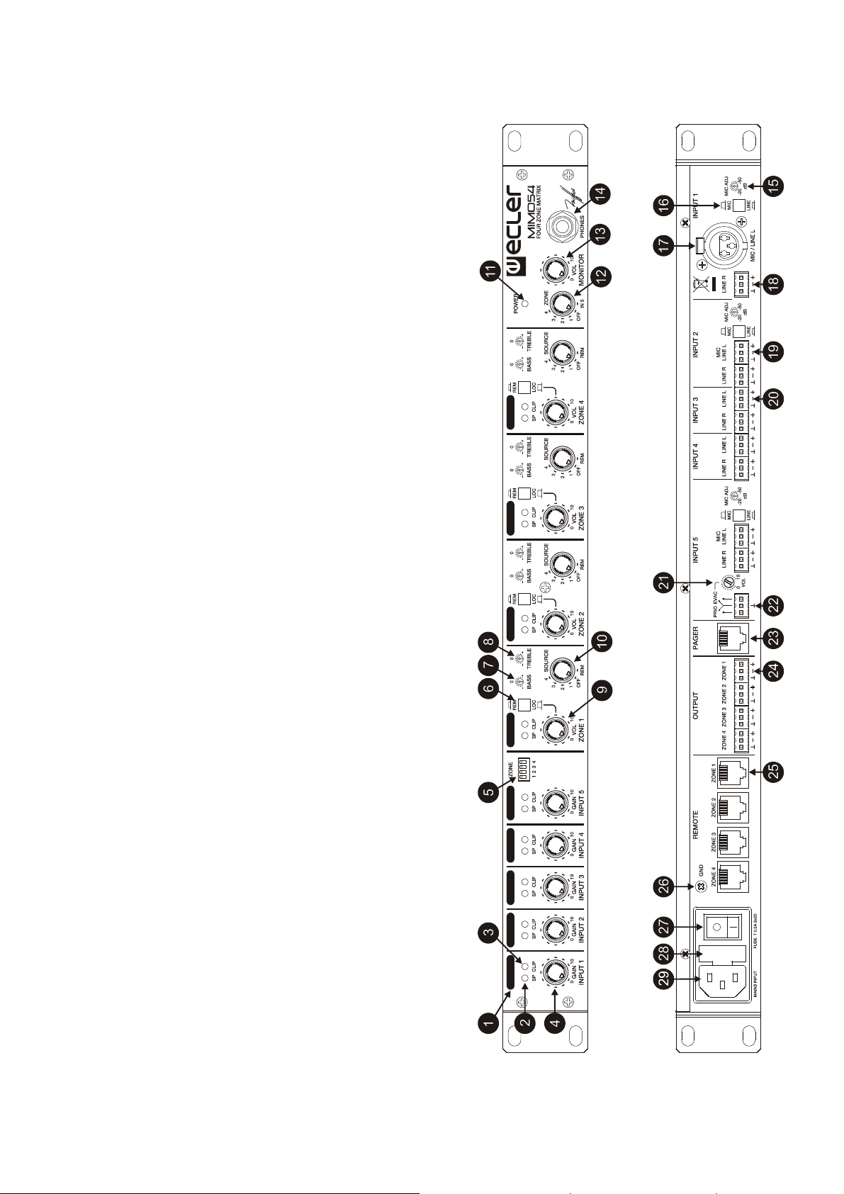
7. FUNCTION LIST 8. FUNCTION DIAGRAM
1. Space reserved for writing
2. Visual indication, SP
3. Visual indication, CLIP
4. Channel volume control, GAIN
5. Destination zone selector, ZONE
6. Local/Remote selector, LOC / REM
7. Bass control, BASS
8. Treble control, TREBLE
9. Volume control OUTPUT, VOL ZONE
10. Input selector, SOURCE
11. Visual indication, ON
12. Phones source selector, ZONE
13. Volume control for the headphones output, VOL
14. Headphones connection stereo jack, PHONES
15. Input sensitivity adjustment, MIC ADJ
16. Input selector, MIC / LINE
17. Signal input XLR3 connector, MIC / LINE L
18. Signal input screw terminal, LINE R
19. Signal input screw terminal, MIC / LINE L
20. Signal input screw terminal, LINE L
21. Volume control, EVAC
22. Screw terminal, PRIO / EVAC
23. RJ-45 connector, PAGER
24. Output screw terminal, OUTPUT ZONE
25. RJ-45 connector, REMOTE ZONE
26. Ground terminal, GND
27. Power switch
28. Fuse holder
29. Mains socket
10
Page 11

MANUAL DE INSTRUCCIONES
1. NOTA IMPORTANTE 12
1.1. Precauciones 12
2. INTRODUCCIÓN 12
3. REQUISITOS DE INSTALACIÓN 13
4. ENTRADAS 13
4.1. Entradas 1 a 4, programa 13
4.2. Entrada 5, prioridad 14
4.3. Alimentación Phantom 15
5. SALIDAS 15
5.1. Salidas de zona 15
5.2. Salida de auriculares 15
6. CONSIDERACIONES Y PUESTA EN MARCHA 15
6.1. Encendido 15
6.2. Ganancia de las entradas 15
6.3. Selección de destino entrada nº 5 / señal de micrófono de la MPAGE4 16
6.4. Ecualización 17
6.5. Ajuste de volumen de salidas 17
6.6. Conexión de controles remotos de pared y consola MPAGE4 17
6.7. Sistema de monitorización auditiva 18
6.8. Tapones de seguridad 18
6.9. Bucles de masa, ruido de fondo 18
6.10. Identificación de entradas y zonas 18
6.11. Limpieza 18
7. LISTA DE FUNCIONES 19
8. DIAGRAMA DE FUNCIONES 19
9. DIAGRAMA DE CONFIGURACIÓN 38
10. POSICIÓN DE LOS LATERALES 39
11. CARACTERÍSTICAS TÉCNICAS 40
12. DIAGRAMA DE BLOQUES 41
Todos los datos están sujetos a variación debida a tolerancias de producción. ECLER S.A. se reserva el derecho de
realizar cambios o mejoras en la fabricación o diseño que pudieran afectar las especificaciones.
11
Page 12

1. NOTA IMPORTANTE
Agradecemos su confianza por haber elegido nuestra matriz de audio MIMO54. Para conseguir
la máxima operatividad y rendimiento de su equipo es MUY IMPORTANTE, antes de su conexión, leer
detenidamente y tener muy presentes las consideraciones que en este manual se especifican.
Para garantizar el óptimo funcionamiento de este aparato recomendamos que su mantenimiento
sea llevado a cabo por nuestros Servicios Técnicos autorizados.
1.1. Precauciones
Este aparato debe ser conectado a tierra mediante su cable de alimentación.
No exponga el aparato a la caída de agua o salpicaduras, no ponga encima objetos con líquido
ni fuentes de llama desnuda, como velas.
Cualquier cambio en la configuración debe ser realizado por personal técnico cualificado.
En caso de requerir alguna intervención y/o conexión desconexión del aparato debe
desconectarse previamente de la alimentación.
En el interior del aparato no existen elementos manipulables por el usuario.
2. INTRODUCCIÓN
MIMO54 es una matriz de audio con 5 fuentes de entrada y 4 salidas de zona, especialmente
diseñada para aplicaciones de sonorización multizona con selección de fuente y ajuste de volumen
independientes. También integra la gestión de señales y mensajes con prioridad para la difusión de
avisos de tipo genérico y/o de evacuación. Los mensajes de voz de tipo genérico pueden enviarse
desde una consola MPAGE4 (opcional), con selección en tiempo real de las zonas de destino, o bien
desde un micrófono de sobremesa o de otro tipo, con selección de las zonas de destino desde el
conmutador ZONE del panel frontal.
Características principales:
4 entradas estéreo de programa (dos de ellas admiten señales micrófono / línea, las otras dos
sólo de línea).
4 salidas monofónicas de zona, con ajuste de tonos de 2 bandas por salida (accesibles en panel
frontal mediante destornillador).
Alimentación Phantom conmutable para las entradas de micrófono.
Quinta entrada de señal (micrófono / línea) con prioridad (modo de funcionamiento dual:
PRIORIDAD / EVACUACIÓN).
Selección de fuente y ajuste de volumen de salida independiente (por zona).
Conectividad con paneles de control remoto para selección de fuente y ajuste de volumen de
zonas.
Conectividad con consola de avisos MPAGE4 (opcional) para las funciones de envío de
mensajes de voz con selección de zona(s) de destino en tiempo real (“paging”)
Selección de modo de control de zonas local o remoto (desde el frontal del aparato o desde los
paneles de control remoto).
Sección de monitoraje mediante auriculares.
Conectores Euroblock en entradas y salidas (la entrada nº 1 incluye también conector tipo XLR
para la señal MIC / LINE L).
Controles de panel frontal reemplazables por tapones de seguridad (incluidos) para evitar
manipulaciones indeseadas.
12
Page 13

3. REQUISITOS DE INSTALACIÓN
MIMO54 ha sido especialmente diseñado para su ubicación en muebles rack de 19", ocupando
una unidad de altura.
Dos consideraciones deben tenerse muy presentes en el momento de buscar la ubicación de su
MIMO54: por un lado la máxima comodidad de utilización y por el otro permitir un fácil acceso en la
realización de las conexiones, de las que el equipo va a ser punto de llegada y partida.
Dado que el consumo del MIMO54 es muy bajo, éste no precisa ventilación forzada. Sin
embargo, debe evitarse que esté expuesto a una temperatura extrema y que la atmósfera del local en
que esté emplazado sea lo más seca y limpia de polvo posible.
Debe procurarse situar el equipo alejado de fuentes de ruido (variadores de tensión, motores,
etc...) así como de los cables de red.
El MIMO54 funciona con tensión alterna de 90 a 264V y 47 a 63 Hz. Este aparato equipa una
fuente de alimentación sobredimensionada capaz de adaptarse sin ningún tipo de ajuste a la tensión de
red de cualquier país del mundo.
Para protegerlo de eventuales sobrecargas, el MIMO54 está protegido con un fusible de red (28)
de 0,5A temporizado. En el caso de que éste se fundiera se sustituiría por otro de idénticas
características. EN NINGÚN CASO DEBE PONERSE UN FUSIBLE DE VALOR MÁS
ELEVADO.
PRECAUCIÓN: El cambio de fusibles debe ser realizado por personal técnico cualificado.
4. ENTRADAS
El MIMO54 admite dos tipos de entradas de audio balanceadas: micrófono (MIC) y línea (LINE)
estéreo.
4.1. Entradas 1 a 4, programa
Las vías de entrada 1 y 2 admiten señales de micrófono o línea. Las vías 3 y 4 admiten señales
de línea únicamente. Finalmente, la vía 5, reservada para las señales con prioridad, admite señales de
micrófono o línea.
Los conectores de las entradas son todos en formato Euroblock, excepto en el caso del conector
MIC / LINE L de la entrada 1, tipo XLR.
En el caso de los conectores Euroblock el conexionado es el siguiente:
Vivo o señal directa > Terminal +
Frío o señal invertida > Terminal Masa > Terminal
Y para el conector XLR:
Vivo o señal directa > Terminal 2
Frío o señal invertida > Terminal 3
Masa > Terminal 1
Los micrófonos deben ser de baja impedancia (de 200 a 600 ) y monofónicos. Para conexiones
NO balanceadas cortocircuitar a masa el terminal 3 o negativo.
En las entradas que disponen de selección MIC / LINE es preciso ajustar a la posición de trabajo
adecuada el conmutador correspondiente del panel posterior:
Pulsado: señal de línea
No pulsado: señal de micrófono
13
Page 14

NOTA: En el modo micrófono se habillita el ajuste de sensibilidad ubicado junto al pulsador posterior,
rotulado como MIC ADJ.
El ajuste de ganancia de cada fuente de entrada (1 a 5) se efectúa mediante el control giratorio
rotulado como GAIN en el panel frontal (uno por entrada). Consulte la sección 6. CONSIDERACIONES
para más información.
Las entradas LINE estéreo admiten señales de nivel de línea de 0 dBV (1 V) procedentes de
reproductores de CD, DVD, dispositivos multimedia, MP3, sintonizadores de radio, receptores de TV,
etc. NO PUEDEN CONECTARSE directamente a este equipo platos giradiscos, ya que ninguna de las
entradas del MIMO54 dispone de previo RIAA.
4.2. Entrada 5, prioridad
La señal conectada a la entrada nº 5 se procesa como señal prioritaria sobre el resto, trabajando
en dos posibles modos:
Modo Prioridad ó Talkover:
Atenúa la señal de programa presente en cualquier de las salidas de zona de destino,
superponiendo a ella la señal existente en la entrada nº 5. La selección de las zonas de
destino se puede realizar desde los microinterruptores del panel frontal (rotulados como
ZONE), o bien desde las teclas de selección de zonas de la consola opcional MPAGE4
(vea el apartado “6.3. Selección de destino entrada nº 5 / señal de micrófono de la
MPAGE4” para más información).
Nota: También es posible emplear una consola MPAGE4 y, simultáneamente, dejar
algunas zonas permanentemente seleccionadas como destino de los mensajes,
empleando para ello el conmutador ZONE del panel frontal. Dichas zonas (de selección
permanente) siempre recibirán los mensajes de voz enviados desde la unidad MPAGE4,
independientemente de si se han seleccionado o no mediante su botonera
La activación del modo de prioridad puede realizarse mediante detección automática de
presencia de señal en la 5ª entrada, o bien por cierre del contacto libre de potencial
rotulado como PRIO en el panel posterior.
La selección del modo de activación (por detección de señal o por cierre de contacto, por
defecto en modo detección de señal), atenuación (-20, -30 ó –80 dB, -30 dB por defecto)
y tiempo de recuperación (1, 2 ó 3 segundos, 2 segundos por defecto) se realizan
mediante puentes internos o jumpers. Consulte la sección 9. DIAGRAMA DE
CONFIGURACIÓN para más información.
Modo Emergencia / Evacuación:
Enmudece la señal de programa presente en TODAS las salidas de zona de la unidad,
reemplazándola por la señal existente en la entrada nº 5.
Adicionalmente, los ajustes de volumen de salida de las zonas, tanto los del panel frontal
como los de los paneles remotos, son ignorados, siendo la difusión de la señal realizada
a un volumen predefinido gracias al control rotulado como EVAC VOL del panel posterior.
La activación de este modo se realiza únicamente mediante cierre del contacto
libre de
potencial rotulada como EVAC en el panel posterior.
14
Page 15

4.3. Alimentación Phantom
El aparato dispone de un puente interno o jumper que actúa sobre la activación general de la
alimentación Phantom para todas las entradas de micrófono, y que posibilita el conexionado de
micrófonos de condensador. Consulte la sección 9. DIAGRAMA DE CONFIGURACIÓN para más
información.
5. SALIDAS
5.1. Salidas de Zona
El MIMO54 dispone de cuatro salidas principales o de zona, todas ellas balanceadas y con
conectores tipo Euroblock: ZONE 1, ZONE 2, ZONE 3 y ZONE 4.
Se realizará la conexión del conector Euroblock como se indica:
Vivo o señal directa > Terminal +
Frío o señal invertida > Terminal Masa > Terminal
En dichas salidas un circuito balanceador simula un transformador. En caso de querer usar una
salida en modo no balanceado debe cortocircuitarse a masa la patilla de salida no utilizada. De no
hacerlo así la señal de salida no tendrá el nivel ni la calidad adecuados.
5.2. Salida de auriculares
La salida de auriculares de la sección MONITOR, rotulada como PHONES, permite realizar una
escucha de la señal reproducida en cualquiera de las salidas de zona, de 1 a 4, así como de la señal
entrante en la quinta entrada del equipo, reservada para las señales prioritarias.
Para obtener el mejor rendimiento en su funcionamiento, los auriculares deberán ser de alta
impedancia (200 a 600). Se conectarán a la salida PHONES (14) del panel frontal mediante un
conector jack normalizado de 1/4" estereofónico, correspondiendo el aro central al canal derecho, la
punta al izquierdo y el aro posterior a la masa. El conmutador ZONE (12) permitirá realizar la selección
de la señal a escuchar, a un volumen definido por el control giratorio VOL.
6. CONSIDERACIONES Y PUESTA EN MARCHA
6.1. Encendido
Éste se realizará directamente mediante el interruptor de red (27). Aunque el ruido producido por
la puesta en marcha del MIMO54 es mínimo, es muy recomendable poner en marcha todos los aparatos
de acuerdo con la siguiente secuencia: fuentes de sonido, unidad de mezclas, procesadores y
ecualizadores y, finalmente, amplificadores de potencia. El apagado de los aparatos debe realizarse en
la secuencia inversa. Siguiendo este orden los transitorios producidos por el encendido o apagado de
los aparatos no afectarán a los siguientes en la cadena, permaneciendo inaudibles.
6.2. Ganancia de las entradas
La ganancia de cada entrada se regula mediante el control de volumen GAIN (4)
El indicador de presencia de señal SP (2) se ilumina para advertir de la existencia de la misma
en dicha entrada.
El indicador CLIP (3) advierte de la proximidad a la saturación de la vía. Como regla general
nunca debe iluminarse de forma permanente.
15
Page 16

La entrada número 5 dispone de un ajuste GAIN en el panel frontal que actúa como control
general del envío de dicha señal hacia las salidas de zona cuando se trabaja en el modo Prioridad (ver
4.2. Entrada 5, prioridad). Adicionalmente, existen 4 potenciómetros de ajuste en el interior de la unidad
que permiten atenuar la señal enviada desde la 5ª entrada hacia las 4 zonas de salida de forma
independiente, personalizando de esta forma el volumen al que se escuchará en las diferentes zonas el
contenido sonoro de dicha entrada en modo Prioridad. Consulte también la sección 9. DIAGRAMA DE
CONFIGURACIÓN para obtener información acerca de la ubicación y ajuste de estos potenciómetros.
6.3. Selección de destino entrada nº 5 / señal de micrófono de la MPAGE4
Use el conmutador de 4 vías rotulado como ZONE en el panel frontal, junto al ajuste de ganancia
INPUT 5, para definir las zonas de destino de dicha entrada cuando se trabaje en modo Prioridad (ver
sección 4.2. Entrada prioritaria). Las zonas de salida (de 1 a 4) se habilitan como destino de la entrada
nº 5 cuando su correspondiente interruptor se halla activado (posición hacia abajo).
Adicionalmente, puede emplearse una consola MPAGE4 para el envío de mensajes de voz con
selección de las zonas de destino en tiempo real. La MPAGE4 dispone en su panel de control de un
micrófono de cuello de cisne y 6 teclas de usuario:
ZONE 1 a 4: teclas de selección de zona(s) de destino de los mensajes. Disponen de un
indicador LED que se ilumina cuando la tecla se halla presionada, quedando
seleccionada la zona en cuestión. Se trata de teclas con enclavamiento mecánico (se
activan al pulsarlas una vez y se desactivan al pulsarlas de nuevo)
ALL: selecciona todas las zonas (1, 2, 3 y 4) como destino de los mensajes de voz.
También es con enclavamiento y también dispone de un indicador LED que se ilumina
cuando la tecla se halla presionada
PAGE: pulsador sin enclavamiento pero con indicador LED, que habilita el envío del
mensaje mientras se halla presionado, finalizando el envío cuando se libera la presión
sobre él (función “push to talk”). En caso de que la unidad MPAGE4 esté configurada
para la emisión de una melodía de carillón, éste se reproducirá en primer término en el
instante en que se pulsa la tecla PAGE
Al emplear una consola MPAGE4 con el MIMO54 es preciso tener en cuenta las siguientes
consideraciones:
El selector de sensibilidad MIC/LINE de la entrada 5 debe estar ajustado en la posición
LINE
El puente interno PRIO MODE que define el modo de actuación de la función
PRIO/EVAC es preferible que se halle en la posición CONTACT (activación por cierre de
contacto mediante las teclas de la MPAGE4). Por defecto se encuentra en la posición
VOICE (activación automática mediante detección de nivel de entrada)
También es posible emplear una consola MPAGE4 (opcional) y, simultáneamente, dejar algunas
zonas permanentemente seleccionadas como destino de los mensajes, empleando para ello el
conmutador ZONE del panel frontal. Dichas zonas (de selección permanente) siempre recibirán los
mensajes de voz enviados desde la unidad MPAGE4, independientemente de si se han seleccionado o
no mediante su botonera.
Si desea trabajar en modo Prioridad y activación por cierre de contacto externo, conecte dicho
contacto externo a los terminales PRIO del panel posterior. Consulte también la sección 9. DIAGRAMA
DE CONFIGURACIÓN para obtener información acerca de la configuración de puentes internos asociados
a este modo.
NOTA: Recuerde que en el otro modo de trabajo de la entrada nº 5 (Evacuación / Emergencia),
el selector de zonas de destino ZONE, así como las zonas seleccionadas en una unidad MPAGE4,
quedan inhabilitados, dado que en dicho modo siempre se enmudece la señal de programa presente en
TODAS las salidas de zona de la unidad, reemplazándola por la señal existente en la entrada nº 5
16
Page 17

6.4. Ecualización
Los controles de tono (7-8) proporcionan una ganancia / atenuación de ±15 dB para cada una de
las bandas BASS (graves) y TREBLE (agudos). Dada la filosofía de utilización del aparato, éste se ha
dotado de un sistema de tonos que requiere un ajuste mediante destornillador, impidiendo así la
manipulación indebida o por error de la unidad durante su utilización habitual.
6.5. Ajustes de volumen de salidas
El volumen de salida de cada zona se puede ajustar desde dos posibles controles:
Desde el control giratorio rotulado como VOL en el panel frontal (uno por zona de salida),
si el pulsador frontal asociado, y rotulado como REM / LOC, se halla en la posición local o
LOC (no pulsado)
Desde el control giratorio del mando de control remoto de pared rotulado como LEVEL
(en caso de estar éste instalado) si el pulsador frontal asociado, y rotulado como REM /
LOC, se halla en la posición remota o REM (pulsado)
La selección de la fuente de escucha para cada zona se puede efectuar desde dos posibles
controles:
Desde el selector giratorio rotulado como SOURCE en el panel frontal (uno por zona de
salida), pudiendo seleccionar una de las entradas 1 a 4 del equipo, o bien ninguna (OFF)
Desde el selector giratorio del mando de control remoto de pared rotulado como INPUT
(en caso de estar dicho mando de control remoto instalado) y siempre que el selector
rotatorio frontal asociado, y rotulado como SOURCE, se halle en la posición remota o
REM. Las opciones disponibles también son las fuentes de entrada 1 a 4, o bien ninguna
(OFF)
Finalmente, y si va a trabajar con la entrada nº 5 en modo Evacuación / Emergencia,
cortocircuite momentáneamente los terminales EVAC del panel posterior, mientras lanza un mensaje de
evacuación hacia la entrada 5 y procede al ajuste de su volumen mediante el control giratorio VOL,
situado junto a dichos terminales.
ATENCIÓN: debe tenerse especial precaución al manipular el nivel general de salida de cada
zona, de manera que nunca queden permanentemente encendidos los indicadores CLIP (saturación o
recorte), ni de las salidas de zona del MIMO54 ni de las etapas de potencia a las que se halle
conectado, sino que lo hagan como máximo al ritmo de las frecuencias más graves del pasaje sonoro.
De lo contrario la señal entregada a las etapas de potencia presentaría altos niveles de distorsión y una
baja calidad acústica e inteligibilidad.
6.6. Conexión de controles remotos de pared y consola MPAGE4
Los controles remotos de pared se conectan a la unidad MIMO54 mediante cable CAT5 estándar
terminado en ambos extremos mediante sendos conectores RJ-45: uno de ellos se introduce en uno de
los puertos REMOTE del panel posterior (ZONE 1, ZONE 2, ZONE 3 o ZONE 4) y el otro el puerto RJ45 del propio control remoto.
Cableado del conector RJ-45
Pin 1 a Pin 1 Blanco/Naranja GND
Pin 2 a Pin 2 Naranja REMOTE VOL (10V÷0V → MIN÷MAX)
Pin 3 a Pin 3 Blanco/Verde GND
Pin 4 a Pin 4 Azul N.C.
Pin 5 a Pin 5 Blanco/Azul N.C.
Pin 6 a Pin 6 Verde VCC (+10V)
Pin 7 a Pin 7 Blanco/Marrón GND
Pin 8 a Pin 8 Marrón REMOTE ZONE (0, 3, 5, 7, 10V → OFF, Z1, Z2, Z3, Z4)
El mismo tipo de cable se emplea para conectar una unidad MPAGE4 (opcional) al conector
PAGER del MIMO54 (23).
6.7. Sistema de monitorización auditiva
17
Page 18

Utilice la sección MONITOR para supervisar el volumen y el contenido sonoro de las zonas de
salida y de la entrada nº 5, tal y como se describe en la sección 5.2. Salida de auriculares.
6.8. Tapones de seguridad
La unidad se entrega con tapones de seguridad, accesorios de gran utilidad si se pretende evitar
manipulaciones indeseadas de los controles giratorios del panel frontal tras la puesta en marcha de la
instalación. Si se desean utilizar dichos tapones, extraiga los controles giratorios tirando de ellos
suavemente y reemplácelos por los tapones suministrados.
6.9. Bucles de masa, ruido de fondo
Debe procurarse en todo momento que las fuentes de señal que lleguen al equipo, así como
todos los aparatos que estén conectados a su salida, no tengan las masas interconectadas, es decir,
que nunca les lleguen las masas por dos o más caminos distintos. De lo contrario se podrían inducir
zumbidos y otros ruidos que degradarían la calidad de la reproducción sonora.
Los blindajes de los cables, de estar conectados a chasis, en ningún momento deberán estar
unidos entre sí. De esta forma evitaremos la formación de bucles de masa.
El equipo ha sido concebido para obtener el menor ruido de fondo posible. Independientemente
de su concepción electrónica, tenga siempre en cuenta que el ruido de fondo total obtenido es el
resultado de la correcta instalación y utilización de todos los equipos que forman parte de la cadena de
audio de la instalación.
6.10. Identificación de entradas y zonas
Existe en el panel frontal espacios reservados (1) para la escritura para poder identificar con
facilidad las entradas i las zonas asignadas.
6.11. Limpieza
La carátula no deberá limpiarse con sustancias disolventes o abrasivas, puesto que se corre el
riesgo de deteriorar la serigrafía. Para su limpieza se utilizará un trapo humedecido con agua y un
detergente líquido neutro, secándola a continuación con un paño limpio. En ningún caso se debe permitir
la entrada de agua por cualquiera de los orificios del aparato.
18
Page 19

7. LISTA DE FUNCIONES 8. DIAGRAMA DE FUNCIONES
1. Espacio reservado para escritura
2. Indicador luminoso, SP
3. Indicador luminoso, CLIP
4. Control de volumen de la vía, GAIN
5. Selector de envio a zonas, ZONE
6. Selector local / remoto, LOC / REM
7. Control de graves, BASS
8. Control de agudos, TREBLE
9. Control de volumen OUTPUT, VOL ZONE
10. Selector de entradas, SOURCE
11. Indicador luminoso, ON
12. Selector de señal auriculares, ZONE
13. Control de volumen auriculares, VOL
14. Jack estéreo conexión auriculares, PHONES
15. Ajuste de la sensibilidad de entrada, MIC ADJ
16. Selector de entradas, MIC / LINE
17. Conector XLR3 entrada de señal, MIC / LINE L
18. Terminales atornillables entrada de señal, LINE R
19. Terminales atornillables entrada de señal, MIC / LINE L
20. Terminales atornillables entrada de señal, LINE L
21. Control de volumen, EVAC
22. Terminales atornillables, PRIO /EVAC
23. Conector RJ-45, PAGER
24. Terminales atornillables de salida, OUTPUT ZONE
25. Conector RJ-45, REMOTE ZONE
26. Borne de toma de masa, GND
27. Interruptor de puesta en marcha
28. Portafusible
29. Base de toma de red
19
Page 20

NOTICE D’UTILISATION
1. NOTE IMPORTANTE 21
1.1. Précautions 21
2. INTRODUCTION 21
3. CONDITIONS D'INSTALLATION 22
4. ENTRÉES 22
4.1. Entrées 1 à 4, programme 22
4.2. Entrée 5, prioritaire 23
4.3. Alimentation fantôme 24
5. SORTIES 24
5.1. Sorties de zone 24
5.2. Sortie casque 24
6. CONSIDÉRATIONS ET MISE EN MARCHE 24
6.1. Mise sous tension 24
6.2. Gain des entrées 25
6.3. Sélection de destination pour l’entrée nº 5 / signal de microphone
de la MPAGE4 25
6.4. Égalisation 25
6.5. Réglages de volume des sorties 25
6.6. Connexion de télécommandes murales et console MPAGE4 26
6.7. Système d’écoute de contrôle (monitoring) 27
6.8. Bouchons de sécurité 27
6.9. Boucles de masse, bruit de fond 27
6.10. Identification des entrées et des zones 27
6.11. Entretien 27
7. LISTE DE FONCTIONS 28
8. SCHÉMA DE FONCTIONS 28
9. SCHÉMA DE CONFIGURATION 38
10. POSITION EQUERRES 39
11. CARACTÉRISTIQUES TECHNIQUES 40
12. SCHEMA DE BLOCS 41
Toutes les valeurs mentionnées dans ce document sont susceptibles d’être modifiées en raison des tolérances de
production. ECLER SA se réserve le droit de changer ou d’améliorer les processus de fabrication ou la présentation de
ses produits, occasionnant ainsi des modifications dans les spécifications techniques.
20
Page 21

1. NOTE IMPORTANTE
Nous vous remercions de la confiance que vous nous avez manifestée en choisissant notre
matrice audio MIMO54. Pour en tirer le meilleur rendement et un fonctionnement maximal, il est TRÈS
IMPORTANT de lire attentivement et de respecter les indications données dans ce manuel avant toute
connexion.
Pour obtenir le meilleur rendement de cet appareil, il est important que le entretien se réalisé par
notre Service Technique Ecler.
1.1. Précautions
Cet appareil doit être impérativement relié à la terre via son câble d'alimentation.
Eviter tout contact avec l'eau. L'appareil doit être installé à l'écart de tout objet contenant un
liquide ou de toute flamme nue, comme une bougie par exemple.
Seul un personnel technique qualifié est habilité à effectuer un changement de configuration.
Avant toute intervention et/ou de connexion/déconnexion, le cordon d'alimentation de
l'appareil doit être préalablement débranché.
Il n'existe aucun élément destiné à l'utilisateur à l'intérieur de l'appareil.
2. INTRODUCTION
La MIMO54 est une matrice audio avec 5 sources d’entrée et 4 sorties de zone, spécialement
conçue pour les applications de sonorisation multizone avec sélection de source et réglage de volume
indépendants. Elle intègre aussi la gestion des signaux et messages prioritaires pour la diffusion
d'annonces génériques et/ou d'évacuation. Les messages vocaux génériques peuvent être envoyés
depuis une console MPAGE4 (optionnelle), avec sélection en temps réel des zones de destination, ou
bien depuis un microphone de bureau ou d'un autre type, avec sélection des zones de destination
depuis le commutateur ZONE de la face avant.
Caractéristiques principales :
4 entrées stéréo de programme (deux d'entre elles admettent des signaux microphone/ligne, les
deux autres seulement des niveaux ligne).
4 sorties monophoniques de zone, avec réglage de tonalité à 2 bandes par sortie (accessible au
moyen d’un tournevis en face avant).
Alimentation fantôme commutable pour les entrées microphone.
Cinquième entrée de signal (microphone/ligne) prioritaire (mode de fonctionnement double :
PRIORITÉ/ÉVACUATION).
Sélection de source et réglage de volume de sortie indépendants (par zone).
Connectique pour panneaux de télécommande servant à la sélection de source et au réglage de
volume des zones.
La console d'annonces MPAGE4 (optionnelle) peut être connectée pour les fonctions d'envoi de
messages vocaux avec sélection de zone (s) de destination en temps réel
Sélection d’un mode de commande local ou distant des zones (depuis l’avant de l'appareil ou
depuis les panneaux de télécommande).
Section d’écoute de contrôle au casque.
Connecteurs Euroblock aux entrées et sorties (l'entrée nº 1 possède aussi un connecteur de type
XLR pour le signal MIC/LINE L).
Commandes de la face avant remplaçables par des bouchons de sécurité (fournis) pour éviter
les manipulations indésirables.
21
Page 22

3. CONDITIONS D'INSTALLATION
La MIMO54 a été spécialement conçue pour un montage en rack 19", occupant une unité de
hauteur.
Deux considérations doivent très être prises en compte pour le placement de votre MIMO54 :
d'une part le confort d'utilisation maximal et d’autre part permettre un accès facile pour les connexions
dont l'équipement sera l’arrivée et le départ.
La consommation de la MIMO54 étant très basse, il n’y a pas besoin de ventilation forcée.
Toutefois, évitez l’exposition à des températures extrêmes et veillez à ce que l'atmosphère du local
d’installation soit la plus sèche et la plus exempte de poussière possible.
Essayez de garder l'appareil à l’écart des sources de bruit (variateurs de tension, moteurs,
etc.…) ainsi que des câbles électriques.
Le MIMO54 fonctionne sur courant alternatif de 90 à 264 V (47 à 63 Hz). Tous les modèles sont
équipés d'une source d'alimentation capable de s'adapter sans aucun réglage spécifique à la tension
secteur en vigueur dans le pays concerné.
Pour la protéger de surcharges éventuelles, la MIMO54 possède un fusible d’alimentation (28)
temporisé de 0,5 A. Si celui-ci venait à fondre, il faudrait déconnecter l'appareil et le substituer par un
autre de même caractéristiques. NE JAMAIS LE REMPLACER PAR UN FUSIBLE DE
VALEUR SUPÉRIEURE.
PRÉCAUTION : Le changement de fusibles doit être effectué par des techniciens qualifiés.
4. ENTRÉES
La MIMO54 accepte deux types d'entrées audio symétriques : microphone (MIC) et ligne (LINE)
stéréo.
4.1. Entrées 1 à 4, programme
Les voies d'entrée 1 et 2 acceptent des signaux microphone ou ligne. Les voies 3 et 4 acceptent
des signaux ligne uniquement. Enfin, la voie 5, réservée aux signaux prioritaires, accepte des signaux
microphone ou ligne.
Les connecteurs des entrées sont tous au format Euroblock, excepté le connecteur MIC/LINE L
de l'entrée 1, de type XLR.
Dans le cas des connecteurs Euroblock, le brochage est le suivant :
Point chaud (signal direct) > Broche +
Point froid (signal inversé) > Broche Masse > Broche
Et pour le connecteur XLR :
Point chaud (signal direct) > Broche 2
Point froid (signal inversé) > Broche 3
Masse > Broche 1
Les micros raccordables sur les entrées doivent être de type mono et à faible impédance (200 à
600). Pour les connexions ASYMÉTRIQUES, raccordez la broche 3 (le négatif) à la masse.
22
Page 23

Pour les entrées qui disposent d’un sélecteur MIC/LINE, il est nécessaire de régler celui-ci sur la
position de fonctionnement adéquate en face arrière :
Enfoncé : signal ligne
Non enfoncé : signal microphone
NOTE: en mode microphone, le réglage de sensibilité MIC ADJ situé à côté du sélecteur arrière est
activé.
Le réglage de gain de chaque source d'entrée (1 à 5) se fait avec le bouton GAIN de la face avant
(un par entrée). Consultez la section 6. CONSIDÉRATIONS pour plus d'informations.
Les entrées LINE stéréo acceptent des signaux de niveau ligne de 0 dBV (1 V) venant de
lecteurs CD, de DVD, de MP3, d’appareils multimédias, de syntoniseurs de radio, de téléviseurs etc. Les
platines tourne-disques NE PEUVENT pas être connectées directement sur l'appareil. Aucune des
entrées du MIMO54 ne dispose d'un préamplificateur RIAA.
4.2. Entrée 5, prioritaire
Le signal envoyé à l'entrée nº 5 est traité comme signal prioritaire par rapport au reste, et cela de
deux façons possibles :
Mode prioritaire ou Talkover :
Atténue le signal de programme présent dans toutes les sorties de zone de destination,
lui superposant le signal arrivant à l'entrée nº5. La sélection des zones de destination
peut se faire depuis les microinterrupteurs de la face avant (intitulés ZONE), ou bien
depuis les touches de sélection de zones de la console optionnelle MPAGE4 (voir le
paragraphe « 6.3. Sélection de destination pour l’entrée nº 5 / signal de microphone de la
MPAGE4» pour plus d'informations)
NOTE: il est aussi possible d'employer une console MPAGE4 et, simultanément, de
laisser certaines zones sélectionnées de façon permanente comme destinations des
messages, en employant pour cela le commutateur ZONE de la face avant. Ces zones (à
sélection permanente) recevront toujours les messages vocaux envoyés depuis l'unité
MPAGE4, indépendamment de leur sélection par leurs touches.
L'activation du mode prioritaire peut être effectuée par détection automatique de la
présence d’un signal en entrée nº 5 ou bien par fermeture du contact libre de potentiel
intitulé PRIO en face arrière.
La sélection du mode d'activation (par détection de signal ou par fermeture de contact, par
défaut en mode détection de signal), de l’atténuation (- 20, -30 ou -80 dB, -30 dB par défaut)
et du temps de récupération (1, 2 ou 3 secondes, 2 secondes par défaut) se fait au moyen
de ponts ou cavaliers internes. Consultez la section 9. SCHÉMA DE CONFIGURATION
pour plus d'informations.
Mode Urgence/Évacuation :
Coupe le signal de programme présent dans TOUTES les sorties de zone de l'unité, le
remplaçant par le signal présent à l'entrée nº 5.
De plus, les réglages de volume de sortie des zones sont ignorés, aussi bien ceux de la
face avant que ceux des panneaux de télécommande, étant donné que la diffusion du
signal se fait à un volume prédéfini par la commande EVAC VOL de la face arrière.
L'activation de ce mode se fait uniquement par fermeture du contact libre
de potentiel
intitulé EVAC en face arrière.
23
Page 24

4.3. Alimentation fantôme
L'appareil dispose d'un pont interne ou cavalier qui agit sur l'activation générale de l'alimentation
fantôme pour toutes les entrées microphone, permettant le branchement de microphones à condensateur.
Consultez la section 9. SCHÉMA DE CONFIGURATION pour plus d'informations.
5. SORTIES
5.1. Sorties de zone
La MIMO54 dispose de quatre sorties principales ou de zone, toutes symétriques et avec des
connecteurs de type Euroblock : ZONE 1, ZONE 2, ZONE 3 et ZONE 4.
Le raccordement du connecteur Euroblock se fait comme indiqué :
Point chaud (signal direct) > Broche +
Point froid (signal inversé) > Broche Masse > Broche
Dans ces sorties, un circuit symétriseur simule un transformateur. Pour utiliser une sortie en
mode asymétrique, il faut court-circuiter à la masse la broche de sortie non utilisée. Sinon, le signal de
sortie n'aura pas ni le niveau ni la qualité adéquats.
5.2. Sortie casque
La sortie casque de la section MONITOR, intitulée PHONES, permet d'écouter le signal produit
par chaque sortie de zone, de 1 à 4, ainsi que le signal reçu par la cinquième entrée de l'équipement,
réservée aux signaux prioritaires.
Pour obtenir le meilleur rendement de fonctionnement, le casque devra être à haute impédance
(200 à 600 Ω). Il sera relié à la sortie PHONES (14) de la face avant au moyen d'un connecteur jack
stéréo normalisé 6,35 mm, la bague correspondant au canal droit, la pointe au canal gauche et le
manchon à la masse. Le commutateur ZONE (12) permettra de sélectionner le signal à écouter, à un
volume défini par le bouton VOL.
6. CONSIDÉRATIONS ET MISE EN MARCHE
6.1. Mise sous tension
Elle se fait directement au moyen de l'interrupteur d’alimentation (27). Bien que le bruit produit
par la mise en marche de la MIMO54 soit minimal, il est très recommandé d’allumer tous les appareils
selon la séquence suivante : sources sonores, unité de mixage, processeurs et égaliseurs, et enfin
amplificateurs de puissance. L’extinction des appareils doit se faire en ordre inverse. En suivant cet
ordre, les transitoires produites par l'allumage ou l’extinction des appareils resteront inaudibles et
n'affecteront pas les appareils suivants dans la chaîne.
24
Page 25

6.2. Gain des entrées
Le gain de chaque entrée est réglé par la commande de volume GAIN (4)
Le témoin de présence de signal SP (2) s’allume pour indiquer l'existence d’un signal à cette
entrée.
Le témoin CLIP (3) indique que la voie est proche de la saturation. En règle générale, il ne doit
jamais être allumé de façon permanente.
L'entrée numéro 5 dispose en face avant d'un réglage GAIN qui agit comme commande générale
de l'envoi de ce signal vers les sorties de zone en mode prioritaire (voir 4.2. Entrée 5, prioritaire). De plus, il
existe dans l'unité 4 potentiomètres de réglage qui permettent d'atténuer individuellement le signal envoyé
par la 5e entrée aux 4 zones de sortie, en personnalisant ainsi le volume d’écoute de cette entrée en mode
prioritaire dans les différentes zones. Consultez aussi la section 9. SCHÉMA DE CONFIGURATION pour
obtenir des informations sur l’emplacement et le réglage de ces potentiomètres.
6.3. Sélection de destination pour l’entrée nº 5 / signal de microphone de la MPAGE4
Utilisez le sélecteur ZONE à 4 positions de la face avant avec le réglage de gain INPUT 5 pour
définir les zones de destination de cette entrée en mode prioritaire (voir section 4.2. Entrée 5, prioritaire).
Les zones de sortie (de 1 à 4) sont choisies comme destination de l'entrée nº 5 quand l’interrupteur
correspondant est activé (position vers le bas).
De plus, on peut employer une console MPAGE4 pour l'envoi de messages vocaux avec
sélection des zones de destination en temps réel. La MPAGE4 dispose dans son panneau de
commande d'un microphone col de cygne et de 6 touches pour l'utilisateur :
ZONE 1 à 4 : touches de sélection de zone de destination des messages. Elles disposent
d'un voyant à DEL qui s’allume quand la touche est enclenchée, signifiant que la zone en
question est sélectionnée. Il s'agit de touches à verrouillage mécanique (activées quand
on les presse une fois et désactivées quand on les presse à nouveau)
ALL : sélectionne toutes les zones (1, 2, 3 et 4) comme destinations des messages
vocaux. Elle a aussi un verrouillage mécanique et et un voyant à DEL qui s’allume quand
la touche est pressée
PAGE : touche sans verrouillage mais avec voyant à DEL, qui permet l'envoi du message
tant qu’elle est pressée, l'envoi s’arrêtant quand on la relâche (fonction « presser pour
parler »). Si l'unité MPAGE4 est configurée pour l'émission d'une mélodie de carillon,
celle-ci se fera en premier quand on presse la touche PAGE
Pour utiliser une console MPAGE4 avec le MIMO54, il s'avère nécessaire de tenir compte des
considérations suivantes :
Le commutateur de sensibilité MIC/LINE de l'entrée 5 doit être réglé sur la position LINE.
Le cavalier interne PRIO MODE qui définit le mode d'action de la fonction PRIO/EVAC
doit de préférence se trouver dans la position CONTACT (activation par fermeture de
contact à l'aide des touches de la console MPAGE4). Par défaut, ce cavalier se trouve
dans la position VOICE (activation automatique à travers la détection de niveau d'entrée).
Il est aussi possible d'employer une console MPAGE4 (optionnelle) et, simultanément, de laisser
certaines zones sélectionnées de façon permanente comme destinations des messages, en employant
pour cela le commutateur ZONE de la face avant. Ces zones (à sélection permanente) recevront
toujours les messages vocaux envoyés depuis l'unité MPAGE4, indépendamment de leur sélection par
leurs touches.
Si vous désirez travailler en mode Prioritaire avec activation par fermeture de contact externe, reliez
ce contact externe aux prises PRIO de la face arrière. Consultez aussi la section 9. SCHÉMA DE
CONFIGURATION pour obtenir des informations sur la configuration des cavaliers internes associés à ce
mode.
NOTE: rappelez-vous que dans l'autre mode de fonctionnement de l'entrée nº 5
(Évacuation/Urgence), le sélecteur de zones de destination ZONE et les zones sélectionnées dans une
25
Page 26

unité MPAGE4, sont désactivés, puisque dans ce mode le signal de programme présent dans TOUTES
les sorties de zone de l'unité est toujours coupé et remplacé par le signal arrivant à l'entrée nº 5.
6.4. Égalisation
Les commandes de tonalité (7-8) fournissent un gain/atténuation de ±15 dB pour chacune des
bandes BASS (graves) et TREBLE (aigus). Vu la philosophie d'utilisation de l'appareil, celui-ci a été doté
d'un système de correction tonale nécessitant un tournevis pour les réglages, empêchant ainsi toute
manipulation illicite ou involontaire de l'unité pendant son fonctionnement normal.
6.5. Réglages de volume des sorties
Le volume de sortie de chaque zone peut être réglé à l’aide de deux commandes :
Le bouton VOL de la face avant (un par zone de sortie) pourvu que le commutateur
REM/LOC associé en face avant soit en position locale ou LOC (non enfoncé)
Le bouton LEVEL de la télécommande murale (s’il y en a une d’installée) pourvu que le
commutateur REM/LOC associé en face avant soit en position télécommande ou REM
(enfoncé)
La sélection de la source d'écoute pour chaque zone peut se faire depuis deux commandes :
Le sélecteur rotatif SOURCE en face avant (un par zone de sortie), permettant de choisir
une des entrées 1 à 4 de l'équipement ou bien aucune (OFF)
Le sélecteur rotatif INPUT de la télécommande murale (s’il y en a une d’installée), pourvu
que le sélecteur rotatif SOURCE associé en face avant se trouve en position
télécommande ou REM. Les options disponibles sont aussi les sources d'entrée 1 à 4 ou
bien aucune (OFF)
Finalement, avec l'entrée nº 5 en mode Évacuation/Urgence, les prises EVAC de la face arrière
sont momentanément court-circuitées tandis qu'un message d'évacuation est envoyé à l'entrée 5 et le
réglage de son volume se fait avec le bouton VOL, situé à côté de ces prises.
ATTENTION : faites particulièrement attention, en manipulant le niveau général de sortie de
chaque zone, que les témoins CLIP (saturation ou écrêtage) des sorties de zone de la MIMO54 et des
étages de puissance auxquels elle est reliée ne soient jamais allumés de façon permanente, mais
uniquement et au maximum au rythme des fréquences les plus graves du passage sonore. Dans le cas
contraire, le signal fourni aux étages de puissance présenterait de hauts niveaux de distorsion, une
faible qualité acoustique et une mauvaise intelligibilité.
6.6. Connexion de télécommandes murales et console MPAGE4
Les télécommandes murales sont reliées à l'unité MIMO54 par câble CAT5 standard terminé aux
deux extrémités par des connecteurs RJ-45 : un des deux s’introduit dans un des ports REMOTE de la
face arrière (ZONE 1, ZONE 2, ZONE 3 ou ZONE 4) et l'autre dans le port RJ-45 de la télécommande
elle-même.
Câblage du connecteur RJ-45
Broche 1 à broche 1 Blanc/Orange GND
Broche 2 à broche 2 Orange REMOTE VOL (10V÷0V → MIN÷MAX)
Broche 3 à broche 3 Blanc/Vert GND
Broche 4 à broche 4 Bleu N.C.
Broche 5 à broche 5 Blanc/Bleu N.C.
Broche 6 à broche 6 Vert VCC (+10V)
Broche 7 à broche 7 Blanc/Marron GND
Broche 8 à broche 8 Marron REMOTE ZONE (0, 3, 5, 7, 10V → OFF, Z1, Z2, Z3, Z4)
Le même type de câble est employé pour relier une unité MPAGE4 (optionnelle) au connecteur
PAGER du MIMO54 (23).
26
Page 27

6.7. Système d’écoute de contrôle (monitoring)
Utilisez la section MONITOR pour superviser le volume et le contenu sonore des zones de sortie
et de l'entrée nº 5, comme décrit dans la section 5.2. Sortie casque.
6.8. Bouchons de sécurité
L'unité est livrée avec des bouchons de sécurité, accessoires d’une grande utilité si l’on veut
éviter les manipulations indésirables des boutons de la face avant après la mise en service de
l'installation. Pour utiliser ces bouchons, retirez les boutons en tirant délicatement sur eux et remplacezles par les bouchons fournis.
6.9. Boucles de masse, bruit de fond
Il faut à tout moment veiller à ce que les sources de signal qui arrivent à l'équipement, ainsi que
tous les appareils qui sont connectés à la sortie, n'aient pas leurs masses interconnectées, c'est-à-dire
que la masse ne doit jamais leur arriver par deux chemins différents ou plus. Dans le cas contraire, cela
pourrait induire des ronflements et autres bruits qui dégraderaient la qualité de la reproduction sonore.
Les blindages des câbles, reliés au châssis, ne devront à aucun moment être réunis. Vous
éviterez ainsi la formation de boucles de masse.
L'équipement a été conçu pour générer le plus petit bruit de fond possible. Indépendamment de
sa conception électronique, prenez toujours en compte le fait que le bruit de fond total obtenu est le
résultat d'une installation et d’une utilisation correctes de tous les équipements faisant partie de la
chaîne audio de l'installation.
6.10. Identification des entrées et des zones
Il existe en face avant des espaces réservés (1) à l'écriture pour pouvoir facilement identifier les
entrées et les zones assignées.
6.11. Entretien
Il est interdit d’utiliser des substances dissolvantes ou abrasives pour nettoyer la face avant,
celles-ci détériorant la sérigraphie. Nettoyer uniquement avec un chiffon humide. Attention! Jamais de
l’eau ou tout autre liquide ne doit pénétrer par les orifices du panneau de commande.
27
Page 28
7. LISTE DE FONCTIONS 8. SCHÉMA DE FONCTIONS
1. Espace réservé pour l’écriture
2. Indicateur lumineux, SP
3. Indicateur lumineux, CLIP
4. Contrôle de volume, GAIN
5. Sélecteur d'envoi aux zones, ZONE
6. Sélecteur local/télécommande, LOC / REM
7. Contrôle des basses, BASS
8. Contrôle des aigus, TREBLE
9. Contrôle de volume OUTPUT, VOL ZONE
10. Sélecteur d'entrées, SOURCE
11. Indicateur lumineux, ON
12. Sélecteur du signal pour casque, ZONE
13. Contrôle de volume pour la sortie casque, VOL
14. Jack de connexion du casque, PHONES
15. Réglage de la sensibilité en entrée, MIC ADJ
16. Sélecteur d’entrée, MIC / LINE
17. Connecteur XLR3 d’entrée de signal, MIC / LINE L
18. Borniers vissables d’entrée de signal, LINE R
19. Borniers vissables d’entrée de signal, MIC / LINE L
20. Borniers vissables d’entrée de signal, LINE L
21. Commande de volume, EVAC
22. Borniers vissables, PRIO/EVAC
23. Connecteur RJ-45, PAGER
24. Borniers vissables de sortie, OUTPUT ZONE
25. Connecteur RJ-45, REMOTE ZONE
26. Prise de masse, GND
27. Interrupteur de mise sous tension
28. Porte-fusible
29. Embase secteur
28
Page 29

BEDIENUNGSANLEITUNG
1. WICHTIGE VORBEMERKUNG 30
1.1. Sicherheitsmaßnahmen 30
2. EINFÜHRUNG 30
3. ANFORDERUNGEN FÜR DIE INSTALLATION 31
4. EINGÄNGE 31
4.1. Eingänge 1 bis 4, Programm 31
4.2. Eingang 5, mit Vorrang 32
4.3. Phantomeinspeisung 33
5. AUSGÄNGE 33
5.1. Zonenausgänge 33
5.2. Kopfhörer-Ausgang 33
6. ZU BERÜCKSICHTIGENDE PUNKTE UND INBETRIEBNAHME 33
6.1. Einschalten 33
6.2. Eingangs-Gain 33
6.3. Wahl des Ziels für Eingang 5 / Mikrofonsignal der MPAGE4 34
6.4. Klangregelung (Equalizer) 35
6.5. Lautstärke-Einstellungen an den Ausgängen 35
6.6. Anschluss von Wandkonsolen für die Fernbedienung und
Konsole MPAGE4 35
6.7. Abhörsystem 36
6.8. Sicherheits-Bedienelemente 36
6.9. Erdungsschleifen, Hintergrundrauschen 36
6.10. Kennung von Eingängen und Zonen 36
6.11. Reinigung 36
7. FUNKTIONSBESCHREIBUNG 37
8. FUNKTIONSÜBERSICHT 37
9. KONFIGURATION 38
10. SEITENLAGE 39
11. TECHNISCHE DATEN 40
12. BLOCKSCHALTBILD 41
Alle Angaben sind ohne Gewähr. Messwerte können produktionsbedingten Schwankungen unterliegen. ECLER S.A.
nimmt sich das Recht heraus Veränderungen am Gerät vorzunehmen, die zur Verbesserung des Produktes beitragen.
29
Page 30

1. WICHTIGE VORBEMERKUNG
Wir bedanken uns für das Vertrauen, das Sie mit der Wahl unserer Audio Matrix MIMO54 in uns
gesetzt haben. Um eine optimale Handhabung und die maximale Leistung zu erhalten, ist es SEHR
WICHTIG, vor dem Anschluss des Geräts die in dieser Anleitung enthaltenen Hinweise aufmerksam
duchzulesen und zu berücksichtigen.
Eventuelle Reparaturen sollten nur von unserer technischen Service Abteilung durchgeführt
werden, um einen optimalen Betrieb sicherzustellen.
1.1. Sicherheitsmaßnahmen
Dieser Apparat muß mittels seines Netzkabels geerdet werden.
Es darf kein Regen oder andere Flüssigkeiten in das Gerät gelangen. Stellen Sie niemals
Flüssigkeitbehälter oder flammende Gegenstände wie z.B. Kerzen auf die Gerätoberfläche.
Überlassen Sie jede Änderung in der Konfiguration des Geräts stets qualifiziertem
Fachpersonal.
Bevor Sie den MIMO54 an andere Geräte anschließen, ziehen Sie immer den Netzstecker.
Im Inneren der Endstufe befinden sich keine für den Benutzer gedachte Bedienelemente.
2. EINFÜHRUNG
MIMO54 ist eine Audio Matrix mit 5 Eingangsquellen und 4 Zonenausgängen, die ganz speziell
für Multizonen-Beschallungsanwendungen entwickelt wurde mit Wahlmöglichkeit der Klangquelle und
unabhängigen Lautstärkeeinstellungen. Das Gerät beinhaltet ausserdem eine Vorrang-Signalverwaltung
für das Aussenden von Meldungen allgemeiner Art und/oder Evakuierungsalarmen. Generische
Sprachnachrichten können von einer MPAGE4-Konsole aus versandt werden (optional), wobei die
Zielzonen in Echtzeit ausgewählt werden können, oder von einem Sprechermikrofon oder ähnlichem,
wobei die Auswahl der Zielzonen mittels des Wahlschalters ZONE an der vorderen Bedientafel erfolgt.
Hauptsächliche Merkmale:
4 programmierbare Stereoeingänge (zwei davon für Mikrofon / Linie, die anderen beiden nur für
Linie),
4 Mono-Zonenausgänge mit 2-Band-Toneinstellung pro Ausgang (zugänglich am Frontpanel mit
Hilfe eines Schraubenziehers),
Umschaltbare Phantomeinspeisung für die Mikrofoneingaänge,
Fünfter Signaleingang (Mikro / Linie) mit Vorrang (Dualbetrieb: VORRANG / EVAKUIERUNG),
Unabhängige Auswahl der Klangquelle und der Ausgangslautstärke (pro Zone),
Anschlussmöglichkeit für Fernsteuerpulte für die Einstellung der Klangquelle und der Lautstärke
der Zonen,
Anschlussmöglichkeiten mit der MPAGE4 Meldungskonsole (optional) für die Sendung von
Sprachnachrichten mit Auswahl der Zielzonen in Echtzeit ("paging").
Wahlweise Bedienung direkt an der Frontseite des Geräts oder Fernbedienung über Fernsteuer-
Pulte,
Abhörsektion mit Kopfhörer-Ausgang,
Euroblock-Schalter an Ein- und Ausgängen (Eingang 1 hat auch einen XLR-Schalter für MIC /
LINE L –Signal),
Bedienelemente der Controller am Frontpanel ersetzbar durch Sicherheits-Abdeckungen
(mitgeliefert) zur Vermeidung von unerwünschten Betätigungen.
30
Page 31

3. ANFORDERUNGEN FÜR DIE INSTALLATION
Die MIMO54 wurde speziell für die Unterbringung in 19“-Racks konstruiert, wo sie eine HE
ausfüllt.
Bei der Suche nach einem geeigneten Ort für die Installation Ihrer MIMO54 sollten Sie zwei
Punkte ganz speziell berücksichtigen: Einerseits eine möglichst bequeme Bedienung des Geräts, und
zum anderen eine leichte Zugänglichkeit für alle vorzunehmenden Anschlüsse für die ein- und
ausgehenden Signale.
Da die MIMO54 sich durch einen äusserst niedrigen Verbrauch auszeichnet, ist eine
Zwangsventilation nicht erforderlich. Trotzdem ist es zu vermeiden, das Gerät extremen Temperaturen
auszusetzen, und die Atmosphäre, in der das Gerät zum Einsatz kommt, sollte so trocken und staubfrei
wie möglich sein.
Das Gerät sollte möglichst fern von Lärmquellen(Spannungswandler, Motoren usw.) und von
Netzkabeln installiert werden.
Der MIMO54 kann mit Wechselstrom zwischen 90 und 264V, 47 bis 63Hz betrieben werden.
Dieses Gerät benutzt ein überdimensioniertes Netzteil. Damit passt es sich ohne irgendwelche
Einstellungen an alle Weltweit auffindbaren Netzspannungen an.
Um das Gerät vor eventuellen Überspannungen zu schützen, ist die MIMO54 mit einer trägen
0,5A-Sicherung geschützt (28). Sollte diese Sicherung durchbrennen, darf sie nur mit einer identischen
Sicherung ersetzt werden. NIEMALS DARF EINE SICHERUNG MIT HÖHEREN WERTEN
EINGESETZT WERDEN.
VORSICHT: Den Wechsel der Sicherung sollte ein qualifizierter Techniker durchführen.
4. EINGÄNGE
Die MIMO54 lässt zwei Arten von symmetrischen Audioausgängen zu: Mikrofon (MIC) und
Stereo-Linie (LINE).
4.1. Eingänge 1 bis 4, Programm
Die Eingangswege 1 und 2 lassen Mikrofon- oder Liniensignale zu. Die Wege 3 und 4 lassen
lediglich Liniensignale zu. Der Kanal 5, letztendlich, ist reserviert für Vorrangssignale und lässt Mikrofonund Linie-Signale zu.
Die Anschlüsse der Eingänge sind alle im Format Euroblock, mit Ausnahme des MIC / LINE L –
Anschlusses von Eingang 1, dieser ist vom Typ XLR.
Die Anschlüsse im Falle der Euroblock-Stecker sind wie folgt:
Hot oder direktes Signal > Pin +
Cold oder Phasenverkehrtes Signal > Pin Masse > Pin
und für den XLR-Stecker:
Hot oder direktes Signal > Pin 2
Cold oder Phasenverkehrtes Signal > Pin 3
Masse > Pin 1
Die angeschlossenen Mikrophone sollten eine niedrige Impedanz (200-600) aufweisen und
monophon sein. Für asymmetrische Anschlüsse muss der Pin 3 mit Masse kurzgeschlossen werden.
31
Page 32

Bei den Eingängen mit Wahlmöglichkeit zwischen MIC und LINE muss der entsprechende
Umschalter an der Rückseite des Geräts auf die richtige Arbeitsposition eingestellt werden.
Schalter gedrückt: Liniensignal
Schalter nicht gedrückt: Mikrofonsignal
ANMERKUNG: In der Betriebsart MIC steht die Einstellung der Sensibilität zur Verfügung. Das
Bedienelement befindet sich neben dem Taster an der Rückseite und ist mit MIC ADJ bezeichnet.
Die Gain-Einstellung der einzelnen Eingangsquellen (1 bis 5) wird mittels Drehregler
(Beschriftung GAIN) an der Vorderseite des Geräts vorgenommen (ein Regler pro Eingang). Für weitere
Informationen siehe Abschnitt 6. ZU BERÜCKSICHTIGEN.
Die Stereo-LINE-Eingänge lassen Signale mit Linienpegel von 0 dBV (1 V) zu, die von CD- oder
DVD-Abspielgeräten kommen oder von Multimediageräten, MP3-Playern, Radioempfängern, TVEmpfängern usw. An den MIMO54 können Sie leider NICHT DIREKT Plattenspieler anschließen, da
kein Kanal über RIAA Vorverstärker verfügt.
4.2. Eingang 5, mit Vorrang
Das am Eingang 5 angeschlossene Signal wird als Vorrangssignal behandelt und arbeitet in zwei
verschiedenen Betriebsarten:
Vorrangsmode oder Talkover:
Dämpft das anliegende Programmsignal an jeglichem, mit Hilfe der Mikroschalter des
vorderen Bedienteils (bezeichnet als ZONE) eingestellten, Zonenausgang und legt das
am Eingang 5 anliegende Signal darüber. Die Auswahl der Zielzonen erfolgt über die
Mikroschalter an der vorderen Bedientafel (bezeichnet als ZONE) oder über die
Zonenwahltasten an der optionalen Konsole MPAGE4 (für nähere Information siehe
Abschnitt "6.3. Wahl des Ziels für Eingang 5 / Mikrofonsignal der MPAGE4").
ANMERKUNG: Es ist auch möglich, eine MPAGE4-Konsole zu verwenden und
gleichzeitig einige Zonen als permanente Empfängerzonen für Nachrichten ausgewählt zu
lassen. Hierfür ist der Wahlschalter ZONE an der vorderen Bedientafel zu verwenden.
Besagte Zonen (permanente Empfängerzonen) empfangen die von der MPAGE4-Konsole
versandten Nachrichten immer, unabhängig davon, ob sie mit den Bedienelementen der
Konsole ausgewählt wurden oder nicht.
Die Aktivierung des Vorrangsmodes kann über automatisches Feststellen des Anliegens
eines Signals am Eingang 5 erfolgen, oder aber über das Schliessen des potentialfreien
Kontakts an der Rückseite des Geräts, der mit PRIO beschriftet ist.
Die Einstellung der Aktivierung des Vorrangsmodes (über Feststellung eines anliegenden
Signals oder über Schliessen des Kontakts, wobei das Feststellen des anliegenden
Signals die Standardeinstellung ist), des Dämpfungsgrads (-20, -30 oder -80 dB,
Standardeinstellung -30 dB), sowie der Erholungszeit (1, 2 oder 3 Sekunden,
Standardeinstellung 2 Sekunden) geschieht über interne Brücken oder Jumper. Für
weitere Informationen siehe Abschnitt 9, KONFIGURATIONSDIAGRAMM.
Betriebsart Notfall / Evakuierung:
Bringt die an SÄMTLICHEN Zonenausgängen des Geräts anliegenden Signale zum
Verstummen und ersetzt diese durch das Signal, das am Eingang 5 anliegt.
Gleichzeitig werden sämtliche Lautstärkeeinstellungen der Zonenausgänge, sowohl an
der vorderen Bedientafel als auch an den Bedienkonsolen zur Fernbedienung, ausser
Kraft gesetzt und das Signal wird mit der Lautstärke ausgesendet, die an dem mit EVAC
VOL bezeichneten Regler an der Rückseite des Geräts voreingestellt ist.
Die Aktivierung dieser Betriebsart ist nur möglich über Schliessen des potentialfreien
Kontakts, bezeichnet als EVAC, an der Rückseite des Geräts.
32
Page 33

4.3. Phantomeinspeisung
Das Gerät verfügt über eine interne Brücke oder Jumper, welcher sich auf die allgemeine
Aktivierung der Phantom-Einspeisung für alle Mikrofon-Eingänge auswirkt und den Anschluss von
Kondensator-Mikrofonen ermöglicht. Für weitere Informationen siehe Abschnitt 9,
KONFIGURATIONSDIAGRAMM.
5. AUSGÄNGE
5.1. Zonenausgänge
Die MIMO54 hat vier Haupt- oder Zonenausgänge, alle vier sind symmetriert und mit Euroblock-
Anschlüssen ausgestattet: ZONE 1, ZONE 2, ZONE 3 und ZONE 4.
Der Anschluss des Euroblock-Steckers ist wie folgt auszuführen:
Hot oder direktes Signal > Pin +
Cold oder Phasenverkehrtes Signal > Pin Masse > Pin
An diesen Ausgängen simuliert ein Symmetrier-Schaltkreis das Verhalten eines Transformators.
Soll ein Ausgang asymmetrisch benutzt werden, so ist der nicht benutzte Ausgangspin mit Masse
kurzzuschließen. Geschieht dies nicht, so hat das Ausgangssignal weder den geeigneten Pegel noch
die geeignete Qualität.
5.2. Kopfhörer-Ausgang
Der Kopfhörer-Ausgang der Abhör-Sektion (MONITOR), bezeichnet als PHONES, erlaubt das
Abhören des reproduzierten Signals en jedem der Zonenausgänge (von 1 bis 4) sowie des eingehenden
Signals am fünften Eingang des Geräts, der für Vorrangssignale reserviert ist.
Um eine optimale Leistung zu erzielen, sollten Kopfhörer von hoher Impedanz (200 a 600) zur
Anwendung kommen. Die Kopfhörer werden am PHONES-Ausgang (14) der vorderen Bedientafel mit
Hilfe eines ¼” Stereo-Standard-Jacksteckers angeschlossen, wobei der mittlere Ring dem rechten Kanal
entspricht, die Spitze dem linken und der hintere Ring der Masse. Der Umschalter ZONE (12) erlaubt die
Einstellung des Signals, das abgehört werden soll. Die Lautstärke wird mit Hilfe des Drehreglers VOL
eingestellt.
6. ZU BERÜCKSICHTIGENDE PUNKTE UND INBETRIEBNAHME
6.1. Einschalten
Das Gerät wird direkt über den Netzschalter (27) eingeschaltet. Wenngleich die
Geräuschentwicklung beim Einschalten der MIMO54 minimal ist, ist es empfehlenswert, alle
angeschlossenen Geräte in der folgenden Reihenfolge einzuschalten: Tonquellen, Mixer, Prozessoren
und Equalizer, und zum Schluss die Verstärker. Das Ausschalten der Geräte sollte in umgekehrter
Reihenfolge erfolgen. Wird diese Reihenfolge eingehalten, so haben die durch den Ein-/oder
Ausschaltevorgang entstehenden Transienten keinen Einfluss auf die nachgeschalteten Geräte und
bleiben somit unhörbar.
6.2. Eingangs-Gain
Die Gains der Eingänge werden mit Hilfe des GAIN-Reglers (4) eingestellt.
Der Signalpräsenz-Anzeiger SP (2) leuchtet auf, um das Anliegen eines Signals am betreffenden
Eingang anzuzeigen.
Der CLIP-Anzeiger (3) warnt kurz bevor das Audiosignal im Kanal so stark ist, dass es zur
Verzerrung kommen kann. Generell darf diese Anzeige niemals dauerhaft aufleuchten.
33
Page 34

Der Eingang 5 hat eine GAIN-Einstellung an der vorderen Bedientafel, welche zur generellen
Kontrolle des zu den Zonenausgängen gesendeten Signals dient, wenn das Gerät im Vorrangs-Mode
arbeitet (siehe hierzu 4.2 Eingang 5, Vorrang) Zusätzlich gibt es noch 4 Lautstärkeregler im Inneren des
Geräts, mit denen das vom 5. Eingang zu den 4 Zonenausgängen geschickte Signal unabhängig
abgeschwächt werden kann. Auf diese Weise kann die Lautstärke, mit der der klangliche Inhalt dieses
Eingangs im Vorrangs-Mode in den verschiedenen Zonen gehört werden kann, individuell eingestellt
werden. Bezüglich der Anbringung und Einstellung dieser Lautstärkeregler siehe auch Abschnitt 9,
KONFIGURATONSDIAGRAMM.
6.3. Wahl des Ziels für Eingang 5 / Mikrofonsignal der MPAGE4
Benutzen Sie den 4-Wege-Umschalter ZONE an der vorderen Bedientafel, direkt neben dem
Gain-Regler INPUT 5, um die Zielzonen für diesen Eingang festzulegen, wenn das Gerät im VorrangsMode arbeitet (siehe Abschnitt 4.2, Eingang für Vorrangssignale) Die Ausgangszonen (1 bis 4) werden
als Ziele für den Eingang 5 geschaltet, wenn der ihnen entsprechende Schalter aktiviert ist (nach unten
umgelegt).
Des Weiteren kann die MPAGE4-Konsole zum Versenden von Sprachnachrichten auch mit
Anwahl der Zielzonen in Echtzeit verwendet werden. Die MPAGE4 verfügt an der vorderen Bedientafel
über ein Schwanenhalsmikrofon und 6 Benutzertasten.
ZONE 1 bis 4: zur Bestimmung der Zielzone(n) für die Nachrichten. Die Tasten verfügen
über eine LED-Anzeige, die aufleuchtet, wenn eine Taste gedrückt wird, wodurch die
entsprechende Zielzone ausgewählt wird. Die Tasten sind mit mechanischer Verriegelung
ausgestattet (diese wird durch einmaliges Drücken aktiviert und durch erneutes Drücken
wieder deaktiviert).ç
ALL: wählt alle Zonen (1, 2, 3 und 4) als Zielzonen für die Stimmnachrichten aus. Diese
Taste ist ebenfalls mit mechanischer Verriegelung und LED-Anzeige ausgestattet, die
aufleuchtet, wenn die Taste aktiviert ist.
PAGE: Taste ohne Verriegelung, aber mit LED-Anzeige, die das Senden der Nachricht
ermöglicht, während sie gedrückt gehalten wird. Das Senden endet sobald die Taste
losgelassen wird ("push to talk"-Funktion). Sollte die MPAGE4 Einheit für die Wiedergabe
einer Glockenspielmelodie konfiguriert sein, so wird diese als Erstes abgespielt, sobald
der Druck auf die PAGE -Taste erfolgt.
Bei Verwendung einer MPAGE4-Konsole mit dem MIMO54 ist auf folgende Punkte zu achten:
Der Sensibilitätsschalter MIC/LINE von Eingang 5 muss in Stellung LINE stehen.
Die interne Brücke PRIO MODE, die Wirkungsweise der Funktion PRIO/EVAC vorgibt,
sollte am besten in Stellung CONTACT (Aktivierung bei Schließen des Kontakts über die
Tasten von MPAGE4) gesteckt sein. Standardmäßig steckt sie in Position VOICE
(selbsttätige Aktivierung bei Erfassen des Eingangspegels).
Es ist auch möglich, (optional) eine MPAGE4-Konsole zu verwenden und gleichzeitig einige
Zonen als permanente Empfängerzonen für Nachrichten ausgewählt zu lassen. Hierfür ist der
Wahlschalter ZONE an der vorderen Bedientafel zu verwenden. Besagte Zonen (permanente
Empfängerzonen) empfangen die von der MPAGE4-Konsole versandten Nachrichten immer,
unabhängig davon, ob sie mit den Bedienelementen der Konsole ausgewählt wurden oder nicht.
Wollen Sie im Vorrangs-Mode arbeiten und soll dieser durch externen Kontaktschluss aktiviert
werden, so schliessen Sie bitte diesen externen Kontakt an die PRIO-Anschlüsse an der Rückseite des
Geräts an. Siehe hierzu auch Abschnitt 9, KONFIGURATIONSDIAGRAMM. Hier finden Sie
Informationen über die Konfiguration der internen Brücken für diese Betriebsart.
ANMERKUNG: Denken Sie daran, dass bei der anderen Betriebsart des Eingangs Nr. 5
(Evakuierung / Notfall) der Zielzonen-Wählschalter ZONE nicht zur Verfügung steht, da in dieser
Betriebsart grundsätzlich das anliegende Programmsignal ALLER Zonenausgänge des Geräts
stummgeschaltet und durch das Signal des Eingangs 5 ersetzt wird.
34
Page 35

6.4. Klangregelung (Equalizer)
Die Toneinstellungen (7-8) erlauben ein Gain / eine Dämpfung von +
15 dB für jedes BASS- und
TREBLE-Band. Im Einklang mit der Gebrauchsphilosophie des Geräts wurde dieses mit einem
Tonausgleichssystem ausgestattet, das nur mit Hilfe eines Schraubenziehers verstellt werden kann. Auf
diese Weise kann eine unsachgemässe oder irrtümliche Verstellung während des normalen Gebrauchs
des Gerätes vermieden werden.
6.5. Lautstärke-Einstellungen an den Ausgängen
Die Ausgangslautstärke einer jeden Zone kann von zwei verschiedenen Reglern
eingestellt werden:
Drehregler VOL an der Geräte-Vorderseite (ein Regler pro Ausgangszone), wenn der
damit verbundene vordere Taster mit der Bezeichnung REM / LOC auf Position LOC steht
(nicht gedrückt),
Drehregler mit der Bezeichnung LEVEL an der Wandkonsole für die Fernbedienung des
Geräts (sofern installiert), wenn der damit verbundene vordere Taster mit der
Bezeichnung REM / LOC auf Position REM steht (gedrückt).
Die Einstellung der Tonquelle für das Abhören der einzelnen Zonen kann mit zwei verschiedenen
Bedienelementen vorgenommen werden:
Drehwahlschalter mit der Bezeichnung SOURCE an der Vorderseite des Geräts (einer
pro Ausgangszone), wobei einer der vier Eingänge 1 bis 4 eingestellt werden kann oder
kein Eingang (OFF).
Drehwahlschalter mit der Bezeichnung INPUT an der Wandkonsole für die
Fernbedienung des Geräts (sofern installiert), vorausgesetzt, dass der damit verbundene
vordere Drehwahlschalter SOURCE sich in Position REM befindet. Als mögliche Quellen
stehen die Eingänge 1 bis 4 zur Verfügung oder kein Eingang (OFF).
Wollen Sie mit Eingang 5 in der Betriebsart „Evakuierung / Notfall“ arbeiten, so schliessen sie
bitte kurzfristig die Anschlüsse EVAC an der Rückseite des Gerätes kurz, senden sie einen
Evakuierungsbefehl zum Eingang 5 und stellen Sie die Lautstärke mit Hilfe des Drehreglers VOL, der
sich neben diesen Anschlüssen befindet, ein.
ACHTUNG: Bei der Einstellung der allgemeinen Ausgangslautstärke der einzelnen Zonen ist
besonders darauf zu achten, dass die CLIP-Anzeigen (zu hoher Pegel oder Verzerrung) niemals
dauerhaft aufleuchten dürfen, weder an den Zonenausgängen der MIMO54 noch an den Endstufen, an
den diese angeschlossen ist. Die Clip-Anzeigen dürfen maximal im Rhythmus der tiefsten Frequenzen
aufleuchten. Ist dies nicht garantiert, so wird das an die Endstufen übergebene Signal sehr stark verzerrt
sein und somit unverständlich und von schlechter akustischer Qualität.
6.6. Anschluss von Wandkonsolen für die Fernbedienung und Konsole MPAGE4
Die Wandkonsolen für die Fernbedienung werden mit einem Standardkabel der Kategorie 5, das
an beiden Enden mit RJ-45-Steckern versehen ist, mit der MIMO54 verbunden. Ein Stecker wird in eine
der REMOTE-Buchsen an der Rückseite des Geräts eingesteckt (ZONE 1, ZONE 2, ZONE 3 oder
ZONE 4), und der andere in der RJ-45 Buchse an der Konsole.
Verkabelung des RJ-45-Steckers
Pin 1 zu Pin 1 weiss/orange GND
Pin 2 zu Pin 2 orange REMOTE VOL (10V÷0V → MIN÷MAX)
Pin 3 zu Pin 3 weiss/grün GND
Pin 4 zu Pin 4 blau N.C.
Pin 5 zu Pin 5 weiss/blau N.C.
Pin 6 zu Pin 6 grün VCC (+10V)
Pin 7 zu Pin 7 weiss/braun GND
Pin 8 zu Pin 8 braun REMOTE ZONE (0, 3, 5, 7, 10V → OFF, Z1, Z2, Z3, Z4)
35
Page 36

Der gleiche Kabeltyp wird verwendet zum Anschluss einer MPAGE4 (optional) an den Stecker
PAGER des MIMO54 (23).
6.7. Abhörsystem
Machen Sie von der Abhör-Sektion (MONITOR) Gebrauch, um die Lautstärke und den
klanglichen Inhalt der Ausgangszonen und des Eingangs 5 zu überwachen, wie in Abschnitt 5.2,
Kopfhörerausgang, beschrieben.
6.8. Sicherheits-Bedienelemente
Das Gerät wird mit Sicherheits-Bedienelementen ausgeliefert. Dieses Zubehör ist sehr hilfreich,
wenn es darum geht, eine unerwünschte Betätigung der Drehregler an der Vorderseite nach
Inbetriebnahme des Geräts zu vermeiden. Möchten Sie von diesen Sicherheits-Bedienelementen
Gebrauch machen, so entfernen Sie durch leichten Zug die ursprünglich vorhandenen Drehregler und
ersetzen Sie diese durch die Sicherheits-Bedienelemente.
6.9. Erdungsschleifen, Hintergrundrauschen
Es ist stets darauf zu achten, dass die Massen der Apparate, die an Ein- und Ausgänge des
Mischpults angeschlossen sind, getrennt sind, so dass ein Gerät nie mehr als einen Masseweg besitzt.
Ist dies nicht sichergestellt, so kann es zu Brummtönen und anderen Geräuschen kommen, die die
Qualität der Klangwiedergabe beeinträchtigen.
Sollten die Kabelabschirmungen mit dem Gehäuse verbunden sein, so dürfen sie auf keinen Fall
untereinander verbunden sein. Auf diese Weise wird die Bildung von Masseschleifen verhindert.
Das Gerät wurde unter dem Gesichtspunkt der weitestgehenden Vermeidung von
Hintergrundrauschen konzipiert. Unabhängig von der elektronischen Konzeption des Geräts sollten Sie
aber immer bedenken, dass das Hintergrundrauschen in seiner Gesamtheit von einer korrekten
Installation und vom bestimmungsgemäßen Gebrauch sämtlicher angeschlossenen Audiogeräte
abhängt.
6.10. Kennung von Eingängen und Zonen
An der Vorderseite des Geräts sind bestimmte Plätze reserviert (1) für die Anbringung von
Bezeichnungen zur leichten Identifizierung der Eingänge und der zugewiesenen Zonen.
6.11. Reinigung
Die Frontplatte darf nicht mit lösungsmittelhaltigen oder scheuernden Substanzen gereinigt
werden, da hierbei die Oberfläche beschädigt werden könnte. Verwenden Sie zur Reinigung der
Frontplatte ein feuchtes Tuch und etwas milde Seifenlauge. Trocknen Sie danach die Oberfläche
sorgfältig ab. Lassen Sie niemals Wasser in die Öffnungen der Frontplatte gelangen.
36
Page 37

7. FUNKTIONSBESCHREIBUNG 8. FUNKTIONSÜBERSICHT
1. Platz reserviert für Schriftzug
2. LED-Anzeige, SP
3. LED-Anzeige, CLIP
4. Kanalpegel, GAIN
5. Zonenwählschalter, ZONE
6. Wählschalter lokale Bedienung / Fernbedienung,
LOC / REM
7. Tiefen-Regler, BASS
8. Höhen-Regler, TREBLE
9. Lautstärke-Regler OUTPUT, VOL ZONE
10. Wählschalter für Eingänge, SOURCE
11. LED-Anzeige, ON
12. Wählschalter für Kopfhörer-Signal, ZONE
13. Lautstärke-Regler für Kopfhörer-Ausgang, VOL
14. Stereo Kopfhörerbuchse, PHONES
15. Verstärkungsfaktor, MIC ADJ
16. Eingangswahlschalter, MIC / LINE
17. Stecker XLR3 Signaleingang, MIC / LINE L
18. Schraubbare Klemmleiste Signaleingang, LINE R
19. Schraubbare Klemmleiste Signaleingang, MIC / LINE L
20. Schraubbare Klemmleiste Signaleingang, LINE L
21. Lautstärkeregler, EVAC
22. Schraubbare Klemmleiste, PRIO / EVAC
23. RJ-45-Stecker, PAGER
24. Schraubbare Klemmleiste Ausgang, OUTPUT ZONE
25. RJ-45-Stecker, REMOTE ZONE
26. Masseanschluss, GND
27. Netzanschluß
28. Sicherungshalter
29. Netzanschlußbuchse
37
Page 38

9. CONFIGURATION DIAGRAM 9. DIAGRAMA DE CONFIGURACIÓN
9. SCHÉMA DE CONFIGURATION 9. KONFIGURATION
38
Page 39

10. SIDE POSITION 10. POSICIÓN DE LOS LATERALES
10. POSITION EQUERRES 10. SEITENLAGE
39
Page 40

11. TECHNICAL CHARACTERISTICS 11. CARACTERÍSTICAS TÉCNICAS
11. CARACTÉRISTIQUES TECHNIQUES 11. TECHNISCHE DATEN
Inputs Sensitivity nom(*)/Impedance MIC BAL -50(-20)dBV/>2k
LINE (1-2-5) -10dBV/2k
LINE (3-4) -10dBV/50k
Outputs Level/Minimum load OUTPUT BAL 0(+6)dBV*/6001(2)V
HEADPHONES 200mW/200 THD 1%
Remote Analog Control
Frequency response LINE 5Hz-40kHz -3dB
MIC BAL 5Hz-37kHz -3dB
Harmonic distortion LINE <0.08%
MIC BAL <0.1%
CMRR MIC >70dB@1kHz
Signal/Noise ratio LINE >110dB
MIC BAL >100dB
Tone control BASS 100Hz ±15dB
TREBLE 10kHz ±15dB
Talkover TIME 1 / 2 / 3 seg*
EFFECT -20 /-30 / -80 dB*
Phantom voltage +18VDC
Mains 90-264VCA 47-63Hz
Power consumption 29VA
Dimensions Panel 482.6x44mm
Depth 195mm
Weight 2.7kg
(*) Internally selectable
40
Page 41

12. BLOCK DIAGRAM 12. DIAGRAMA DE BLOQUES
12. SCHEMA DE BLOCS 12. BLOCKSCHALTBILD
41
Page 42

42 43
Page 43

Page 44

50.0190.01.02
ECLER Laboratorio de electro-acústica S.A.
Motors 166-168, 08038 Barcelona, Spain
INTERNET http://www.ecler.com e-mail: info@ecler.es
 Loading...