

Page 1

INSTRUCTION MANUAL
MANUAL DE INSTRUCCIONES
NOTICE D’EMPLOI
BEDIENUNGSANLEITUNG
IW6
Page 2

Page 3

3
INSTRUCTION MANUAL
1. IMPORTANT REMARK 04
2. WARNINGS 04
3. INTRODUCTION 04
4. CONNECTIONS 05
5. LOCATION AND ASSEMBLY 06
6. PAINTING 06
7. TECHNICAL CHARACTERISTICS 19
All numbers subject to variation due to production tolerances. ECLER, S.A. reserves the right to make
changes or improvements in manufacturing or design which may affect specifications.
Page 4

4
1. IMPORTANT REMARK
Congratulations! You are the owner of a carefully designed and manufactured equipment.
We thank you for the confidence you've placed in our company when choosing our IW6 loudspeaker
for wall/ceiling mounting.
In order to get the optimum operation and efficiency from this unit, it is VERY IMPORTANT
- before you plug anything - to read this manual very carefully and bear in mind all considerations
specified within it. We strongly recommend that its maintenance be carried out by our Authorized
Technical services.
2. WARNINGS
Never use this unit in the proximity of water. Do not expose the unit to water splashing, nor
place liquid containers on top of it.
Avoid placing the unit next to heat sources such as spotlights or heaters.
Use only the accessories specified by the manufacturer, employing the correct accessories
for each application.
3. INTRODUCTION
ECLER’s IW6 unit, a loudspeaker for wall/ceiling mounting, uses carefully selected
components integrated in a design which allows an easy handling and a fast installation. They also
provide excellent sound quality for high and low frequencies thanks to our infinite speaker philosophy
and to top-performance high frequency transducer.
Because we have included a transformer, the unit are extremely versatile and are easy to
use both in applications with low impedance and in applications running at 100V/70V. All you have to
do is shift the position of the built-in selector.
The transducer used to play low and medium frequencies are made of polypropylene,
giving them maximum, long-term stability and protecting them from environmental factors like heat
and humidity.
Technical specifications:
• 2 way speaker system for wall/ceiling mounting
• 6.5” polypropylene woofer
• 25mm tweeter
• Power: 40W RMS@8Ω
• Sensitivity (1W/1m): 87 dB SPL
• Built-in transformer
• Dimensions: 236x344x67mm
• Installation system: Six revolving fasteners
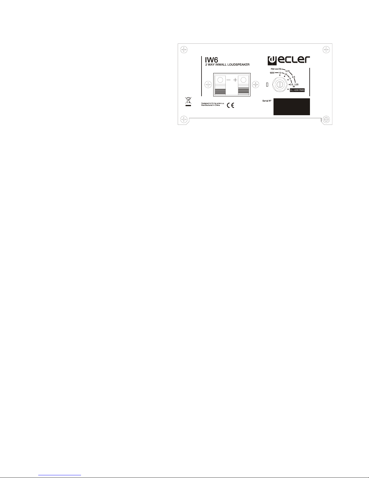
Note: If you use the speaker in 70V installations, the power for the 100V position will be half the
amount shown on the switch. When used in 50V installations, it will be a fourth of the amount.
The IW6 model comes with a protective grill that can be removed with a hook included in
the package. Be careful not to damage the speaker when removing the grill.
Page 5
5
4. CONNECTIONS
The connection terminals are
clamps for stripped wires. Once they are
connected, all you have to do is choose the
unit's power and mode of operation using a
simple screwdriver. Always pay attention to
the polarity.
The IW6 are shipped from
factory with the switch in 100V/70V
position. If it is connected to a lowimpedance amplifier, the speaker will not be damaged, but will perform way below its full
potential. If the speaker is accidentall y connected t o a 100V/70 V line in the 8Ω posi tion, it will
be severely damaged.
Use the 6 revolving fasteners included to easily install the units. For more information on
how to install the units, please see section 5 of this manual.
Page 6
6
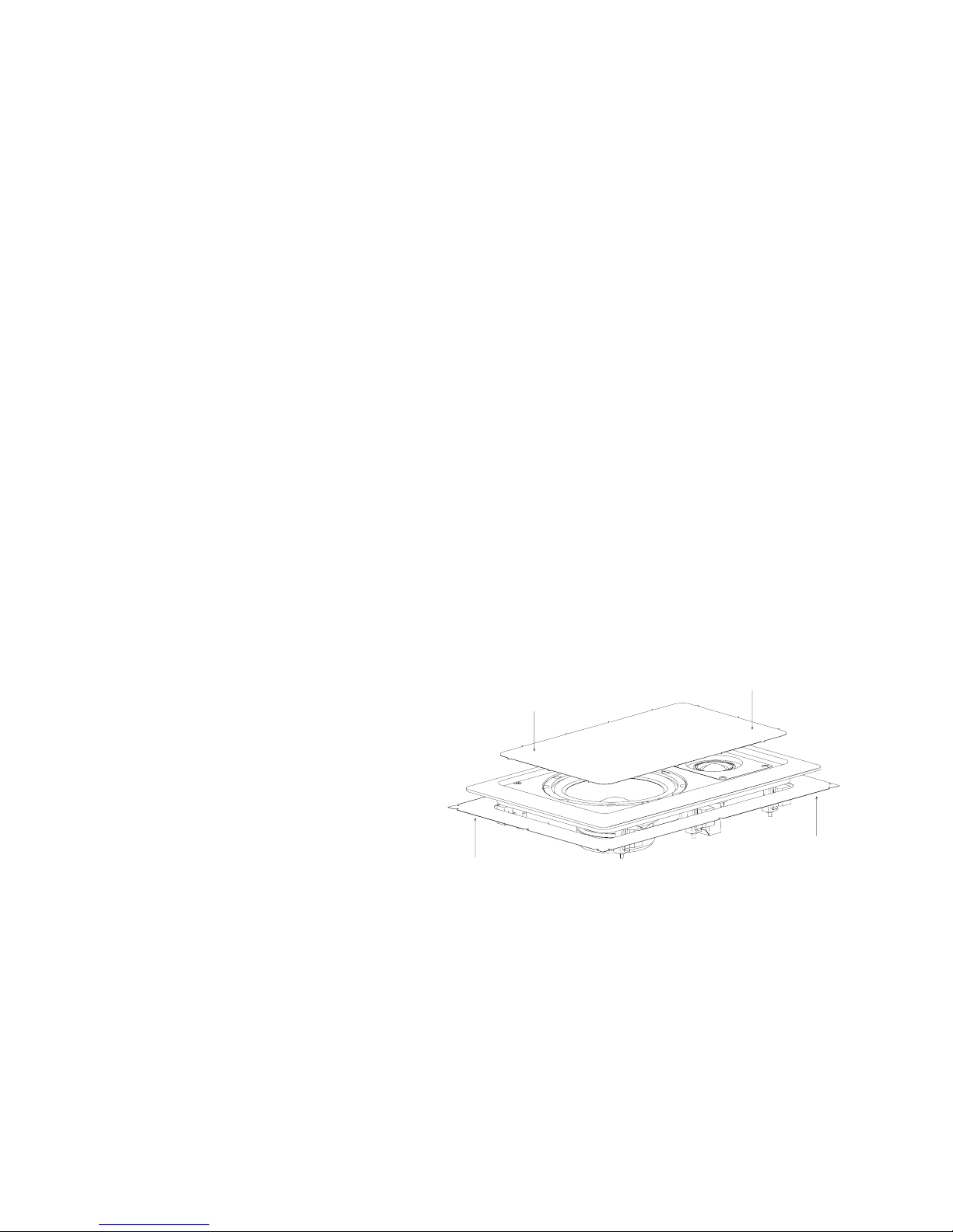
5. LOCATION AND ASSEMBLY
The correct installation of this speaker requires the execution of a rectangular hole at the
location where the speaker is going to be installed as well as the corresponding cables for each unit.
In order to install the speakers correctly:
1. Remove the protective grating from the speaker using the hook provided in the packaging.
2. It is necessary to execute a rectangular hole in the wall or false ceiling. The dimensions of
this hole have to be 193x302mm.
A template for cutting/painting is included with each unit to simplify this process. Once
divided into two, the outer part can be used as pattern to mark the hole on the wall or ceiling, while
the inner part can be used to protect the speaker cone in case of painting the plastic part in another
colour.
3. Use the clamps to connect the unit to the wiring of the system where the speaker is being
installed.
4. Place the speaker in the newly cut hole. Hold the unit with one h and and introduce it into
its location. The six rotary mounting tabs must be tangential to the cut-out.
5. Press each of the 6 screws that are accessible from the front side of the speaker. The
speaker is now fixed in its final position.
6. Reattach the protective grille.
6. PAINTING
The IW6 is designed to be painted, meaning it can be installed anywhere, regardless of
the aesthetic criteria of the place where it will be used.
The following instructions explain the details of painting the unit:
1. Remove the protective grille from
the speaker using the hook
provided in the packaging.
2. Once the cutting/painting pattern
is divided into two, use the inner
part to protect the speakers cone
placing over the cones and
making it fit as well as possible.
The tips that remain after splitting the pattern make it easy to fit this part. The outer part
can be placed on the back of the speaker fitting it to its shape, to protect the speaker’s
back from splashes if a spray is used to paint the unit.
3. Paint the protective grating and the speaker separ ately. Make sure that the small holes in
the grating are not blocked by paint. Use an appropriate air-dry paint.
4. When the paint is dry, remove the protectors. The unit is ready to be installed.
Page 7

7
MANUAL DE INSTRUCCIONES
1. NOTA IMPORTANTE 08
2. PRECAUCIONES 08
3. INTRODUCCIÓN 08
4. CONEXIONADO 09
5. UBICACIÓN Y MONTAJE 10
6 PINTADO 10
7. CARACTERÍSTICAS TÉCNICAS 19
Todos los datos están sujetos a variación debida a tolerancias de producción. ECLER S.A. se
reserva el derecho de realizar cambios o mejoras en la fabricación o diseño que pudieran afectar las
especificaciones.
Page 8

8
1. NOTA IMPORTANTE
Enhorabuena. Vd. posee el resultado de un cuidado diseño y de una esmerada fabricación.
Agradecemos su confianza por haber elegido nuestro altavoz de instalación en pared/techo IW6.
Para conseguir la máxima operatividad y su máximo rendimiento, es MUY IMPORTANTE
antes de su conexión, leer detenidamente y tener muy presentes las consideraciones que en este
manual se especifican. Para garantizar el óptimo funcionamiento, recomendamos que su
mantenimiento sea llevado a cabo por nuestros Servicios Técnicos autorizados.
2. PRECAUCIONES
No utilice este aparato cerca del agua. No exponga los equipos a salpicaduras.
Evite colocar los equipos cerca de fuentes de calor, focos o estufas.
Utilizar únicamente los accesorios especificados por el fabricante y adecuados a cada
cometido.
3. INTRODUCCIÓN
La unidad IW6, altavoz de instalación en pared o techo, de ECLER incorpora una cuidada
selección de componentes en un diseño de uso sencillo que busca la rapidez de instalación.
Además ofrecen una excelente reproducción sonora en graves y agudos gracias a la filosofía bafle
infinito y a un transductor de agudos de excelente comportamiento.
La incorporación de transformador permite la máxima versatilidad de la unidad,
pudiéndose usar de forma intuitiva tanto en aplicaciones de baja impedancia como en línea de
100V/70V, cambiando simplemente de posición el selector incorporado.
El transductor empleado para la reproducción de frecuencias bajas y medias está
realizado en polipropileno lo que asegura una excelente estabilidad del componente en el tiempo y
lo protegen de factores ambientales como el calor y la humedad.
Especificaciones técnicas:
• Altavoz de pared o falso techo 2 vías
• Woofer en polipropileno 6,5”
• Tweeter 25mm
• Potencia 40W RMS@8Ω
• Sensibilidad (1W/1m): 87 dB SPL
• Transformador incorporado
• Dimensiones: 236x344x67mm
• Sistema de instalación: 6 puntos mediante pestaña giratoria
Nota: en caso de utilizar el altavoz en instalaciones a 70V las potencias correspondientes para la
posición 100V se verán reducidas a la mitad de las indicadas en el conmutador. Para el caso de
instalaciones a 50V, a una cuarta parte.
El modelo IW6 incorpora una reja protectora desmontable mediante gancho suministrado.
Tenga precaución de no dañar el altavoz al extraer la reja.
Page 9

9
4. CONEXIONADO
Los terminales de conexión son
de tipo pinza de presión para cable
pelado. Una vez conectado, basta
seleccionar el modo y potencia de trabajo
de la unidad mediante un simple
destornillador. Respete siempre la
polaridad.
La unidad IW6 se sirve de
origen con el conmutador en posición
100V/70V. Si conecta el sistema accidentalmente en baja impedancia 8Ω, no producirá
ningún daño al altavoz pero éste rendirá muy por debajo de sus prestaci ones. En el caso de
conectar accidentalmente el altavoz a una red de 100V/70V en posición 8Ω lo dañará
gravemente.
La instalación de cada unidad se lleva a cabo fácilmente mediante las 6 pestañas
giratorias incorporadas. Para más información sobre el método de instalación consulte el apartado
5 del presente manual.
Page 10

10
5. UBICACIÓN Y MONTAJE
Para la correcta instalación del producto es preciso prever la realización de un orificio
rectangular en el lugar destinado a su ubicación así como el cableado pertinente para cada unidad.
A continuación de detallan los pasos a seguir para una correcta instalación:
1. Retire la reja protectora de la unidad mediante el gancho suministrado.
2. Realice un orificio rectangular en el fals o techo o pared. Las dimensiones necesarias de
dicho orificio son 193x302mm.
Para facilitar este cometido, se suministra con cada unidad una plantilla de corte/pintado. Una
vez separada en dos partes, la parte externa se puede utilizar como plantilla para marcar el orificio
en la pared / techo, mientras que la interna se podrá utilizar para proteger el cono del altavoz si se
desea pintar la parte de plástico de otro color.
3. Realizar la conexión de los cables existentes en la instalación con la unidad mediante las
pinzas de presión.
4. Insertar el altavoz en el orificio practicado. Sostener la unidad con una mano e introducirlo
en su posición teniendo cuidado de que las 6 pestañas giratorias queden en posición
tangencial al corte.
5. Apriete cada uno de los 6 tornillos accesibles desde el frontal de la unidad. El altavoz
quedará entonces fijado en su posición final.
6. Coloque la reja protectora.
6 PINTADO
La unidad IW6 está preparada para ser pintada, de modo que sea factible su instalación
sea cual sea el criterio estético del recinto al que esté destinado su uso.
A continuación se detalla el proceso a seguir para el pintado:
1) Retire la reja protectora de la
unidad mediante el gancho
suministrado
2) Una vez separada la plantilla de
corte/pintado en dos partes,
utilice la parte interna para
proteger el cono del altavoz
colocándola sobre él de manera
que quede ajustada. Las puntas
que han quedado después de la separación de la plantilla en dos partes facilitan el ajuste.
La parte exterior de la plantilla se puede colocar por la parte posterior del altavoz
ajustada a su contorno, para proteger la zona trasera de salpicaduras en caso de pintar
con spray.
3) Pinte la reja protectora y el altavoz por separado, cuidando que no queden obstruid os los
pequeños agujeros de la reja. Utilice pinturas adecuadas de secado al aire.
4) Una vez la pintura esté seca, retire las protecciones y la unidad está lista para ser
instalada.
Page 11

11
NOTICE D’EMPLOI
1. NOTE IMPORTANTE 12
2. PRÉCAUTIONS 12
3. INTRODUCTION 12
4. CONNEXIONS 13
5. MISE EN PLACE ET MONTAGE 14
6 PEINTURE 14
7. CARACTÉRISTIQUES TECHNIQUES 19
Le contenu de ce manuel peut être amené à changer, du fait de tolérances de production. La société
ECLER S.A. se réserve le droit d'apporter des modifications ou des améliorations à la fabrication ou
à la conception du produit, susceptibles d'affecter les spécifications de ce dernier.
Page 12

12
1. NOTE IMPORTANTE
Félicitations. Votre acquisition est le fruit d'une conception soignée et d'une fabrication
exper te. Merci de nous avoir fait confi ance et d'avoir choisi not re IW6, haut-parleur de paroi/plafond à
encastrer.
Pour exploiter au mieux toutes les fonctionnalités et obtenir un rendement maximal, il est
TRÈS IMPORTANT de lire attentivement et de suivre les recommandations de ce manuel avant
toute connexion. Pour garantir un fonctionnement optimal, nous recommandons que toute
maintenance soit effectuée par nos services techniques agréés.
2. PRÉCAUTIONS
N'utilisez pas cet équipement avec de l'eau à proximité. Ne l'exposez pas à des projections
et évitez de placer dessus des récipients qui contiennent des liquides.
Évitez de le placer près de sources de chaleur, foyers ou poêles.
N'utilisez que les accessoires préconisés par le fabricant et adaptés à chaque application.
3. INTRODUCTION
Le haut-parleur à encastrer en paroi ou plafond IW6 d'ECLER comprend une sélection
soigneuse de composants au coeur d'une conception d'utilisation simple ayant pour but la rapidité
d'installation. Grâce au concept baffle infini et à un transducteur d’aigus d’excellente qualité, ces
haut-parleurs permettent une excellente reproduction sonore des graves et des aigus.
Le transformateur incorporé permet une grande flexibilité, car les haut-parleurs peuvent
être utilisés intuitivement dans des applications de faible impédance ou sur une ligne de 100V/70V.
Pour cela, il suffit de changer la position de l’interrupteur correspondant.
Le transducteur employé pour la reproduction des fréque nces basses et moyennes est en
polypropylène pour assurer une excellente stabilité de ce composant dans le temps et le protéger de
facteurs environnementaux comme la chaleur et l'humidité.
Spécifications techniques :
• Haut-parleur 2 voies pour paroi ou faux plafond
• Haut-parleur de graves en polypropylène 6,5”
• Haut-parleur d’aigus 25mm
• Puissance 40 W RMS à 8Ω
• Sensibilité (1W/1m) : 87 dB SPL
• Transformateur incorporé
• Dimensions : 236x344x67mm
• Système d’installation : 6 languettes rotatives
Remarque : si vous utilisez le haut-parleur dans des installations à 70V, les puissances
correspondant à la position de 100V sont réduites à la moitié de celles indiquées sur le
commutateur et, dans le cas d’installations à 50V, à un quart.
Le modèle IW6 comprend une grille de protection démontable au moyen du crochet
fourni. Prenez garde à ne pas endommager le haut-parleur en enlevant la grille.
Page 13

13
4. CONNEXIONS
Les terminaux de connexion sont
de type pince à pression pour câble pelé.
Après avoir effectué la connexion,
sélectionnez le mode et la puissance de
travail de l’appareil au moyen d’un
tournevis. Respectez la polarité.
Le IW6 est fournie avec le
commutateur sur la position 100V/70V.
Si vous branchez accidentellement le
système en faible impédance de 8Ω, cela n’endommagera pas le haut-parleur, mais il
fonctionnera en dessous de ses capacités. Si vous branchez accidentellement le hautparleur à un réseau de 100V/70V en position 8Ω, vous risquez de l’endommager
sérieusement.
Pour installer un haut-parleur, utilisez les 6 languettes rotatives fournies. Pour des
informations complémentaires sur la méthode d’installation, consultez la section 5 de ce manuel.
Page 14

14
5. MISE EN PLACE ET MONTAGE
Pour l'installation correcte du produit, il est nécessaire de prévoir le perçage d'un orifice
rectangulaire à l'endroit voulu ainsi que le câblage adapté à chaque unité.
Suivez les étapes ci-dessous :
1. Retirez la grille protectrice au moyen du crochet fourni.
2. Percez un orifice rectangulaire dans le faux plafond ou la paroi. Les dimensions de cet
orifice doivent être de 193x302mm.
Pour faciliter l’installation, un modèle de coupe est fourni avec chaque appareil. Une fois les
deux parties séparées, la partie externe peut être utilisée comme gabarit pour marquer l'orifice sur
la paroi ou le plafond, tandis que la partie interne pourra servir de masque pour protéger le cône du
haut-parleur si on souhaite peindre la partie en plastique en une autre couleur.
3. Branchez les câbles de l’installation à l’appareil au moyen des pinces de pression.
4. Insérez le haut-parleur dans l’orifice réalisé. Soutenez l'unité d'une main et introduisez-la
dans son emplacement en ayant veillé à ce que les 6 languettes tournantes restent en
position tangentielle à la coupe.
5. Vissez les 6 vis accessibles sur l’avant de l’appareil. Le haut-parleur est fixé.
6. Remettez la grille protectrice en place.
6 PEINTURE
Le IW6 peuvent être peints pour pouvoir être installés dans tous types d’environnements.
Ci-dessous est détaillée la procédure à suivre pour la peinture :
1. Retirez la grille protectrice au
moyen du crochet fourni.
2. Une fois séparé le gabarit de
coupe/masque en deux parties,
utilisez la partie interne pour
protéger le cône du haut-parleur en
l'ajustant dessus. Les pointes
restées après la séparation du
gabarit en deux parties facilitent
l'ajustement. La partie extérieure du gabarit peut être placée sur la partie postérieure du
haut-parleur, adaptée à sa découpe, pour protéger la zone arrière de projections en cas de
peinture à la bombe.
3. Peignez séparément la grille protectrice et le haut-parleur en prenant soin de ne pas
obstruer les trous de la grille. Utilisez une peinture qui sèche à l’air.
4. Lorsque la peinture est sèche, retirez les protections. L’appareil est prêt à être installé.
Page 15

15
BEDIENUNGSANLEITUNG
1. WICHTIGE VORBEMERKUNG 16
2. SICHERHEITSMASSNAHMEN 16
3. EINFÜHRUNG 16
4. VERKABELUNG 17
5. AUFSTELLUNGSORT UND MONTAGE 18
6 LACKIEREN 18
7. TECHNISCHE DATEN 19
Alle angegebenen Werte unterliegen gewissen Schwankungen infolge Produktionstoleranzen.
ECLER S.A. behält sich das Recht zu Änderungen oder Weiterentwicklungen in Produktion oder
Design vor, die Abweichungen der technischen Daten zur Folge haben können.
Page 16

16
1. WICHTIGE VORBEMERKUNG
Herzlichen Glückwunsch! Sie besitzen hiermit ein hochwertiges Gerät als Ergebnis eines
hohen Entwicklungsaufwandes und sorgfältiger Fertigungsplanung. Wir danken Ihnen für das mit der
Auswahl unseres Wand-/Deckenlautsprechers IW6 in uns gesetzte Vertrauen.
Um die maximale Leistung und eine zuverlässige Funktion zu erreichen, ist es sehr
WICHTIG, vor dem Anschluß der Boxen alle Ausführungen in dieser Bedienungsanleitung genau zu
lesen. Eventuelle Reparaturen sollten nur von unserer technischen Service Abteilung durchgeführt
werden, um einen optimalen Betrieb sicherzustellen.
2. SICHERHEITSMASSNAHMEN
Es darf kein Regen oder andere Flüssigkeiten in das Gerät g elangen. Stellen Sie niemals
Flüssigkeitbehälter auf die Gerätoberfläche.
Halten Sie das Gerät von Hitzequellen wie Heizgeräte oder Scheinwerfer fern.
Benutzen Sie ausschließlich das von ECLER empfohlene Montagezubehör und
verwenden Sie das Zubehör immer zum richtigen Zweck.
3. EINFÜHRUNG
Der ECLER IW6 Lautsprecher zur Wand- oder Dachmontage überzeugt durch seine
sorgfältig ausgewählten Komponenten sowie sein Design, welches für eine problemlose Bedienung
und eine schnelle Montage ausgelegt ist. Der Lautsprecher besticht durch eine ausgezeichnete
Wiedergabequalität von Höhen und Tiefen dank der Philosophie der unendlichen Schallwand und
einem Höhenwandler mit exzellenter Performance.
Der bei integrierte Transformator sorgt für maximale Vielseitigkeit beim Einsatz der
Lautsprecher, die mit intuitiver Benutzerführung sowohl für Anwendungen mit Niedrigimpedanz als
auch mit 100V/70V-Leitungsspannung verwendet werden können. Die Leistungswahl erfolgt über
den eingebauten Wahlschalter.
Der verwendete Woofer zur Wiedergabe tiefer und mittlerer Frequenzen ist aus
Polypropylen, was ihn äusserst langlebig macht und ihn ausserdem vor Umgebu ngseinflüssen wie
Hitze und Feuchtigkeit schützt.
Technische Merkmale:
• 2-Wege-Lautsprecher zur Montage an der Wand oder an abgehängter Decke
• Woofer aus 6,5”-Polypropylen
• Tweeter 25mm
• Leistung 40W RMS@8Ω
• Empfindlichkeit (1W/1m): 87 dB SPL
• Integrierter Transformator
• Abmessungen: 236x344x67mm
• Einbausystem: 6 Drehverbinder
Hinweis: Wenn der Einbau-Lautsprecher in 70V-Installationen verwendet wird, halbieren sich die
auf dem Schalter für die Position 100V angegebenen Leistungswerte entsprechend. Für 50VInstallationen betragen sie ein Viertel.
Page 17

17
Das Modell IW6 verfügt über ein Schutzgitter, welches mit Hilfe des mitgelieferten Hakens
abgenommen werden kann. Achten Sie darauf, den Lautsprecher nicht zu beschädigen, wenn Sie
das Gitter abnehmen.
4. VERKABELUNG
Der Lautsprecher haben
Anschlussklammern, in die das nackte
Kabel eingeklemmt wird. Nach Anschluss
der Kabel werden mittels Schraubenzieher
der Modus und die Betriebsleistung
eingestellt. Achten Sie dabei auf die
richtige Polarität.
Die IW6 werden von werkseitig
mit dem Wahlschalter in Position
100V/70V geliefert. Wenn das System
versehentlich an Niedrigimpedanz 8Ω angeschlossen wird, werden die Lautsprecher nicht
beschädigt. Sollte ein auf Position 8Ω eingestellter Lautsprecher versehentlich an ein
100V/70V-Netz angeschlossen werden, würde dies jedoch zu einer ernsthaften
Beschädigung des Geräts führen.
Die Lautsprecher werden mit 6 Drehverbindern befestigt, die zum Lieferumfang gehören.
Ausführliche Informationen zum Einbau der Lautsprecher finden Sie in Kapitel 5 dieses Handbuchs.
Page 18

18
5. AUFSTELLUNGSORT UND MONTAGE
Für eine korrekte Montage des Geräts ist es notwendig, am vorgesehenen
Anbringungsort eine rechteckige Öffnung vorzubereiten sowie die entsprechende Verkabelung für
jedes Gerät vorzusehen.
Einbauschritte:
1. Schutzgitter mit dem mitgelieferten Haken abnehmen.
2. Bereiten Sie in der abgehängten Decke oder in der Wand eine rechteckige Öffnung mit
den Abmessungen 193x302mm vor.
Als Einbauhilfe wird eine Schablone zum Aufzeichnen der Einbauöffnung mitgeliefert.
Nachdem die beiden Hälften voneinander getrennt wurden, kann die äussere Hälfte als Schablone
zum Anzeichnen der rechteckigen Öffnung verwendet werden, während die innere Hälfte dazu
benutzt werden kann, den Lautsprecherkegel zu schützen, falls die Umlackierung des Plastikteils
gewünscht sein sollte.
3. Die Kabel an die Anschlussklemmen der Lautsprecher anschließen.
4. Den Lautsprecher in die Einbauöffnung einsetzen. Halten Sie das Gerät mit einer Hand
fest und führen Sie es in seine Montageposition ein, wobei darauf zu achten ist, dass die 6
drehbaren Montagelaschen tangential zum Montageausschnitt ausgerichtet sein müssen.
5. Die drei 6 Schrauben von der Vorderseite des Geräts aus festziehen. Der Lautsprecher
sitzt jetzt fest in seiner Einbauposition.
6. Zum Abschluss das Schutzgitter wieder anbringen.
6 LACKIEREN
Die Serie IC kann lackiert werden und ist so für jede Deckenoberfläche geeignet.
Nachfolgend wird die Vorgehensweise für das Lackieren des Geräts geschildert:
1. Schutzgitter mit dem
mitgelieferten Haken abnehmen.
2. Nachdem die Schablone für den
Montageausschnitt/Anstrich in
zwei Teile getrennt wurde,
verwenden Sie das innere Teil,
um den Lautsprecherkegel zu
schützen, indem Sie dieses Teil
eng anliegend um den Kegel
legen. Die Spitzen, die bei der Trennung der Schablone entstanden sind, erleichtern die
Anpassung. Die äussere Hälfte der Schablone kann, falls ein Farbspray verwendet wir,
dazu dienen, das rückwärtige Teil des Lautsprechers vor Farbspritzern zu schützen.
Hierzu muss die Schablone an den Umriss dieses Teils angepasst werden.
3. Das Schutzgitter und den Lautsprecher einzeln lackieren und darauf achten, dass die
kleinen Öffnungen des Gitters nicht verstopfen. Geeignete lufttrocknende Farbe
verwenden.
4. Wenn die Farbe trocken ist, können die Schutzvorrichtungen entfernt werden, und der
Lautsprecher ist bereit zum Einbau.
Page 19

19
7. TECHNICAL CHARACTERISTICS 7. CARACTERÍSTICAS TÉCNICAS
7. CARACTÉRISTIQUES TECHNIQUES 7. TECHNISCHE DATEN
Nominal low impedance 8Ω
RMS power 40W
100V Transformer Taps 1.25, 2.5, 3.75, 7.5W
70V Transformer Taps 2.5, 5, 7.5, 15W
Frequency response (-6dB) 70Hz – 20kHz
Sensitivity 1W/1m 87dB
Dimensions of the hole for installation 193x302mm
Required depth 68mm
Weight 2.1kg
Page 20

ECLER Laboratorio de electro-acústica S.A.
Motors 166-168, 08038 Barcelona, Spain
INTERNET http://www.ecler.com e-mail: info@ecler.es
50.0133.01.01
 Loading...