

Page 1

INSTRUCTION MANUAL
MANUAL DE INSTRUCCIONES
NOTICE D’EMPLOI
BEDIENUNGSANLEITUNG
IC SB10
Page 2

2
Page 3

3
INSTRUCTION MANUAL
1. IMPORTANT REMARK 04
2. WARNINGS 04
3. INTRODUCTION 04
4. CONNECTIONS 05
5. LOCATION AND ASSEMBLY 05
6. PAINTING 06
7. TECHNICAL CHARACTERISTICS 19
All numbers subject to variation due to production tolerances. ECLER, S.A. reserves the right to make
changes or improvements in manufacturing or design which may affect specifications.
Page 4

4
1. IMPORTANT REMARK
Congratulations! You are the owner of a carefully designed and manufactured equipment.
Thank you for choosing our IC SB10 model inceiling subwoofer.
In order to get the optimum operation and efficiency from this unit, it is VERY IMPORTANT
- before you plug anything - to read this manual very carefully and bear in mind all considerations
specified within it. We strongly recommend that its maintenance be carried out by our Authorized
Technical services.
2. WARNINGS
Never use this unit in the proximity of water. Do not expose the unit to water splashing, nor
place liquid containers on top of it.
Avoid placing the unit next to heat sources such as spotlights or heaters.
Use only the accessories specified by the manufacturer, employing the correct accessories
for each application.
3. INTRODUCTION
The IC SB10 model incorporates carefully selected components in an easy-to-use design
that is quick and reliable to install. It also provides excellent bass sound quality thanks to our infinite
baffle philosophy and a top-performance transducer.
The IC SB10 has a built-in transformer, making it extremely versatile and easy to use both
in applications with low impedance and in applications running at 100V/70V. All you have to do is
shift the position of the built-in selector switch.
The technical specifications of the IC SB10 include:
10” inceiling woofer
Power: 100W RMS @ 8Ω
Sensitivity (1W/1m): 96 dB SPL
Built-in transformer: 7.5 / 15 / 30 / 60 W @100V
3.75 / 7.5 / 15 / 30W @70V
Internal Low Pass Filter: fc = 150Hz
External diameter: 335mm
Cut-out diameter: 307mm
Installation system: four points fixed with a revolving fastener. Accessories included.
Page 5

5
4. CONNECTIONS
The connection terminals are of spring
clamp type for peeled cable. Once they are
connected, all you have to do is choose the unit's
power and mode of operation using a simple
screwdriver. Always pay attention to the polarity.
The IC SB10 is delivered with the switch in the 100V/70V position. If you
accidentally hook it up to a low-impedance system, no damage will be done to the speaker,
but it will perform far under its real capabilities. If you accidentally connect the speaker to a
100V/70V network in the 8Ω position, serious damage will be caused to the speaker.
It is easy to install the IC SB10 with the four revolving fasteners incorporated. For more
information on how to install the IC SB10, please see section 5 of this manual.
5. LOCATION AND ASSEMBLY
To install this product correctly, you must be prepared to cut circular holes where you would
like to place the speakers and have the wiring necessary for each unit.
In order to install the speakers correctly:
1. Remove the protective grating from the speaker using the hook provided in the packaging.
2. Cut a circular hole in the false ceiling.
A template for cutting/painting is included with each unit to simplify this process. Once the
unit is separated into two parts, the outside part can be used as a template to make the hole in the
ceiling, and the inner disk can be used to protect the speaker cone if you would like to paint the
plastic another colour.
3. Use the clamps to connect the unit to the wiring of the system where the speaker is being
installed.
4. Place the speaker in the newly cut hole. Hold it in place with your hand and push it into
place, all the while making sure that the 4 revolving fasteners are drawn back.
5. Press each of the 4 screws that are accessible from the front side of the speaker. The
speaker is now fixed in its final position.
6. Reattach the protective grille.
Each IC SB10 speaker comes with a set of accessories that make it easy to install in drop
ceilings, resulting in an installation that is even more solid and reliable.
- A C-shaped metal ring.
- Two brackets especially designed for use in 600mm ceiling grids.
Page 6
6
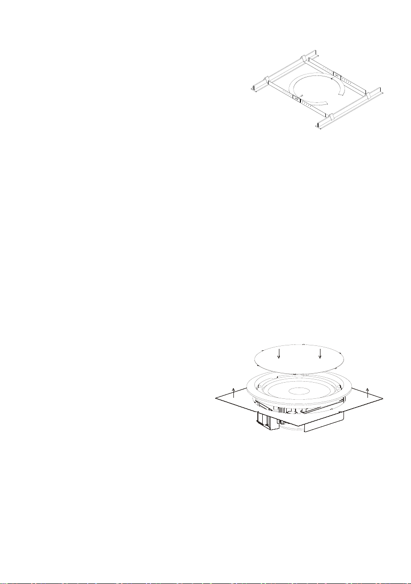
1. Insert the ring in the hole previously drilled in the
ceiling according to the procedure described on
the preceding page.
2. Place the ring in the hole as illustrated. It is
important that the tabs on the side of the ring are
placed exactly as shown.
3. Insert the brackets into the hole, fix them in place
on the tabs on the side of the metal ring and line
them up so that both V-shaped ends rest on the
ceiling’s existing grid.
4. Use the screws provided to attach the brackets to the ring.
The metal ring can also be use for non-drop ceilings, being as it distributes the weight
uniformly across the contact surface.
N.B.: The high performance of the IC SB10 speaker can result in substantial vibrations,
which may be transmitted to the existing materials and structures of the ceiling where it is installed.
Depending on the materials and structures in place, we recommend using shock absorbing
materials, such as neoprene, to eliminate undesired vibrations.
6. PAINTING
The IC SB10 is designed to be painted, meaning it can be installed anywhere, regardless
of the design and look of the place where it will be used.
Follow these instructions to paint the speaker:
1. Remove the protective grating from the speaker using the hook provided in the packaging.
2. Once the cut/paint template has been separated into two parts, use the inside disk to
protect the speaker cone. Place it tight on the cone. The points still on disk after it has
been separated help to fix it tight into place. The outside part of the template can be put
on the back part of the speaker, lining
it up with the plastic circle, to protect
the back part from splattering if you
are using spray paint.
3. Paint the protective grating and the
speaker separately. Make sure that
the small holes in the grating are not
blocked by paint. Use an appropriate
air drying paint.
4. When the paint is dry, remove the
protectors. The unit is ready to be
installed.
Page 7

7
MANUAL DE INSTRUCCIONES
1. NOTA IMPORTANTE 08
2. PRECAUCIONES 08
3. INTRODUCCIÓN 08
4. CONEXIONADO 09
5. UBICACIÓN Y MONTAJE 09
6. PINTADO 10
7. CARACTERÍSTICAS TÉCNICAS 19
Todos los datos están sujetos a variación debida a tolerancias de producción. ECLER S.A. se
reserva el derecho de realizar cambios o mejoras en la fabricación o diseño que pudieran afectar las
especificaciones.
Page 8

8
1. NOTA IMPORTANTE
Enhorabuena. Vd. posee el resultado de un cuidado diseño y de una esmerada fabricación.
Agradecemos su confianza por haber elegido nuestro subgrave de instalación en techo IC SB10.
Para conseguir la máxima operatividad y su máximo rendimiento, es MUY IMPORTANTE
antes de su conexión, leer detenidamente y tener muy presentes las consideraciones que en este
manual se especifican. Para garantizar el óptimo funcionamiento, recomendamos que su
mantenimiento sea llevado a cabo por nuestros Servicios Técnicos autorizados.
2. PRECAUCIONES
No utilice este aparato cerca del agua. No exponga los equipos a salpicaduras.
Evite colocar los equipos cerca de fuentes de calor, focos o estufas.
Utilizar únicamente los accesorios especificados por el fabricante y adecuados a cada
cometido.
3. INTRODUCCIÓN
El modelo IC SB10 incorpora una cuidada selección de componentes en un diseño de uso
sencillo que busca la rapidez y fiabilidad de instalación. Además ofrece una excelente reproducción
sonora en graves gracias a la filosofía bafle infinito y a un transductor de excelente comportamiento.
La incorporación de transformador permite la máxima versatilidad de la unidad,
pudiéndose usar de forma intuitiva tanto en aplicaciones de baja impedancia como en línea de
100V/70V, cambiando simplemente de posición el selector incorporado.
Se describen a continuación las características técnicas del IC SB10
Unidad de refuerzo en graves de instalación en techo de 10”
Potencia 100W RMS @ 8
Sensibilidad (1W/1m): 96dB SPL
Transformador incorporado: 7.5 / 15 / 30 / 60 W @100V
3.75 / 7.5 / 15 / 30W @70V
Filtro-paso-bajos interno: fc = 150Hz
Diámetro externo: 335mm
Diámetro de corte: 307mm
Sistema de instalación: cuatro puntos mediante pestaña giratoria. Accesorios incluidos.
Page 9

9
4. CONEXIONADO
Los terminales de conexión son de tipo
pinza de presión para cable pelado. Una vez
conectado, basta seleccionar el modo y potencia
de trabajo de la unidad mediante un simple
destornillador. Respete siempre la polaridad.
El IC SB10 se sirve de origen con el conmutador en posición 100V/70V. Si se
conecta accidentalmente a un sistema de baja impedancia no producirá ningún daño al
altavoz pero éste rendirá muy por debajo de sus prestaciones. En el caso de conectar
accidentalmente el altavoz a una red de 100V/70V en posición 8 lo dañará gravemente.
La instalación de cada unidad se lleva a cabo fácilmente mediante las 4 pestañas
giratorias incorporadas. Para más información sobre el método de instalación consulte el apartado
5 del presente manual.
5. UBICACIÓN Y MONTAJE
Para la correcta instalación del producto es preciso prever la realización de orificios
circulares en los lugares destinados a su ubicación así como el cableado pertinente para cada
unidad.
A continuación de detallan los pasos a seguir para una correcta instalación:
1. Retire la reja protectora de la unidad mediante el gancho suministrado.
2. Realice un orificio circular en el falso techo.
Para facilitar este cometido, se suministra con cada unidad una plantilla de corte/pintado.
Una vez separada en dos partes, la parte externa se puede utilizar como plantilla para marcar el
orificio en el techo, mientras que el disco interno se podrá utilizar para proteger el cono del altavoz
si se desea pintar la parte de plástico de otro color.
3. Realizar la conexión de los cables existentes en la instalación con la unidad mediante las
pinzas de presión.
4. Insertar el altavoz en el orificio practicado. Sostener la unidad con una mano e
introducirlo en su posición teniendo cuidado de que las 4 pestañas giratorias queden en
posición retraída.
5. Apriete cada uno de los 4 tornillos accesibles desde el frontal de la unidad. El altavoz
quedará entonces fijado en su posición final.
6. Coloque la reja protectora.
Cada modelo IC SB10 se suministra con un conjunto de accesorios que facilitan su
instalación en falso techo montado en perfilería, otorgando al conjunto solidez y fiabilidad
adicionales en la instalación.
- Un anillo metálico en forma de “C”.
- Dos puentes de anclaje preparados para su uso en perfilería de 600mm.
Page 10

10
1. Inserte el anillo a través del agujero practicado
en el techo según el procedimiento indicado en
la página anterior.
2. Sitúe el anillo en el orificio según se indica en
el gráfico siguiente. Es importante que las
aletas laterales del anillo queden posicionadas
tal y como se indica.
3. Introduzca los puentes de anclaje por el orificio
y encájelos en las aletas laterales del anillo
metálico previamente colocado y alinéelos de manera que ambos extremos en forma de
“V” descansen sobre la perfilería del techo existente.
4. Asegure al anillo los puentes así colocados mediante el uso de la tornillería suministrada.
El anillo metálico que se suministra puede ser útil incluso para uso en techos no
suspendidos, ya que distribuye el peso de la unidad uniformemente sobre la superficie de contacto.
Nota: dado su rendimiento, la unidad IC SB10 puede general vibración substancial que
puede darse el caso que se transmita a través de los materiales y estructuras del techo en que se
instale. Dependiendo de ellos, resulta recomendable el uso de materiales amortiguadores, como por
ejemplo neopreno, para eliminar vibraciones indeseadas.
6. PINTADO
El IC SB10 está preparado para ser pintado, de modo que sea factible su instalación sea
cual sea el criterio estético del recinto al que esté destinado su uso.
A continuación se detalla el proceso a seguir a tal efecto:
1. Retire la reja protectora de la unidad mediante el gancho suministrado
2. Una vez separada la plantilla de corte/pintado en dos partes, utilice el disco interno para
proteger el cono del altavoz colocándolo sobre él de manera que quede ajustado. Las
puntas que han quedado en el disco después de la separación de la plantilla en dos
partes facilitan el ajuste. La parte exterior de la plantilla se puede colocar por la parte
posterior del altavoz ajustada al círculo
de plástico, para proteger la zona
trasera de salpicaduras en caso de
pintar con spray.
3. Pinte la reja protectora y el altavoz por
separado, cuidando que no queden
obstruidos los pequeños agujeros de la
reja. Utilice pinturas adecuadas de
secado al aire.
4. Una vez la pintura esté seca, retire las
protecciones y la unidad está lista para
ser instalada.
Page 11

11
NOTICE D’EMPLOI
1. NOTE IMPORTANTE 12
2. PRÉCAUTIONS 12
3. INTRODUCTION 12
4. CONNEXIONS 13
5. MISE EN PLACE ET MONTAGE 13
6. PEINTURE 14
7. CARACTÉRISTIQUES TECHNIQUES 19
Le contenu de ce manuel peut être amené à changer, du fait de tolérances de production. La société
ECLER S.A. se réserve le droit d'apporter des modifications ou des améliorations à la fabrication ou
à la conception du produit, susceptibles d'affecter les spécifications de ce dernier.
Page 12

12
1. NOTE IMPORTANTE
Félicitations. Votre acquisition est le fruit d'une conception soignée et d'une fabrication
experte. Nous vous remercions de votre confiance pour avoir choisi notre enceinte d’installation sur
plafond IC SB10.
Pour exploiter au mieux toutes les fonctionnalités et obtenir un rendement maximal, il est
TRÈS IMPORTANT de lire attentivement et de suivre les recommandations de ce manuel avant
toute connexion. Pour garantir un fonctionnement optimal, nous recommandons que toute
maintenance soit effectuée par nos services techniques agréés.
2. PRÉCAUTIONS
N'utilisez pas cet équipement avec de l'eau à proximité. Ne l'exposez pas à des projections
et évitez de placer dessus des récipients qui contiennent des liquides.
Évitez de le placer près de sources de chaleur, foyers ou poêles.
N'utilisez que les accessoires préconisés par le fabricant et adaptés à chaque application.
3. INTRODUCTION
Le modèle IC SB10 intègre une sélection soignée des composants sur un design
d’utilisation simple qui recherche la rapidité et la fiabilité d’installation. De plus, il offre une excellente
reproduction sonore dans les graves grâce à la philosophie baffle infini et à un transducteur
d’excellente qualité.
Le transformateur incorporé permet une grande flexibilité de l’unité, car elle peut être
utilisée intuitivement dans des applications de faible impédance ou sur une ligne de 100V/70V. Pour
cela, il suffit de changer la position du sélecteur correspondant.
Les caractéristiques techniques de l’IC SB10 sont décrites ci-dessous.
Unité de renfort dans les graves de l’installation sur plafond de 10”
Puissance 100W RMS @ 8
Sensibilité (1W/1m) : 96 dB SPL
Transformateur incorporé : 7.5 / 15 / 30 / 60 W @100V
3.75 / 7.5 / 15 / 30W @70V
Filtre passe-bas interne : fc = 150Hz
Diamètre externe : 335 mm
Diamètre de coupe : 307 mm
Système d’installation : quatre points au moyen de l’onglet rotatif. Accessoires compris.
Page 13

13
4. CONNEXIONS
Les terminaux de connexion sont de
type pince étau pour câble pelé. Après avoir
effectué la connexion, sélectionnez le mode et la
puissance de travail de l’appareil au moyen d’un
tournevis. Respectez la polarité.
L’IC SB10 est fourni avec le commutateur sur la position 100V/70V. Si vous le
branchez accidentellement à un système de basse impédance, cela n’endommagera pas le
haut-parleur, mais il fonctionnera très en dessous de ses capacités. Si vous branchez
accidentellement le haut-parleur à une ligne de 100V/70V en position 8 , vous risquez de
l’endommager sérieusement.
L’installation de chaque unité est facilement effectuée à l’aide des 4 languettes rotatives
fournis. Pour des informations complémentaires sur la méthode d’installation, consultez la section 5
de ce manuel.
5. MISE EN PLACE ET MONTAGE
Pour installer correctement l’appareil, il faut percer des orifices circulaires aux
emplacements souhaités et effectuer les connexions nécessaires.
Suivez les étapes ci-dessous :
1. Retirez la grille protectrice au moyen du crochet fourni.
2. Percez un orifice circulaire dans le faux plafond.
Pour faciliter l’installation, un modèle de coupe est fourni avec chaque appareil. Ce modèle
comporte deux parties : la partie externe peut être utilisée comme modèle pour marquer
l’emplacement de l’orifice au plafond, et le disque interne permet de protéger le cône du hautparleur si vous souhaitez repeindre la partie en plastique.
3. Branchez les câbles de l’installation à l’appareil au moyen des pinces de pression.
4. Insérez le haut-parleur dans l’orifice réalisé. Tenir l’appareil d’une main et le mettre en
place en vérifiant que les languettes rotatives restent en retrait.
5. Vissez les 4 vis accessibles sur l’avant de l’appareil. Le haut-parleur est fixé.
6. Remettez la grille protectrice en place.
Chaque modèle IC SB10 est fourni avec un ensemble d’accessoires qui facilitent son
installation sur les faux plafonds montés sur rail, offrant solidité et fiabilité supplémentaires à
l’ensemble de l’installation.
- Un anneau métallique en forme de "C".
- Deux ponts de fixation préparés pour son utilisation sur rail de 600 mm.
Page 14

14
1. Insérez l’anneau au travers du trou pratiqué dans
le plafond selon la procédure indiquée à la page
précédente.
2. Placez l’anneau dans l’orifice comme indiqué sur
le dessin. Il est important que les ailettes latérales
de l’anneau soient placées comme indiqué.
3. Introduisez les ponts de fixation par l’orifice et
encastrez-les dans les ailettes latérales de
l'anneau métallique, préalablement placé, et
alignez-les de sorte que les deux extrémités en forme de "V" reposent sur les rails du
plafond existants.
4. Fixez les ponts à l’anneau en utilisant les vis fournies.
L’anneau métallique qui est fourni peut également être utile pour une utilisation sur des
plafonds non suspendus, car il répartit le poids de l’unité uniformément sur la surface de contact.
Remarque : étant donné son rendement, l’unité IC SB10 peut provoquer une vibration
substantielle qui peut se transmettre au travers des matériels et des structures du plafond où elle est
installée. En fonction de ceux-ci, il peut être recommandé d’utiliser des matériaux d’amortissement,
comme par exemple le néoprène, pour éliminer les vibrations inutiles.
6. PEINTURE
L’IC SB10 peut être peint pour pouvoir être installé quel que soit le critère esthétique de
l’enceinte pour laquelle son utilisation est prévue.
Le processus à suivre à cet effet est détaillé ci-dessous :
1. Retirez la grille protectrice au moyen du crochet fourni.
2. Séparez le modèle de coupe/peinture en deux et placez le disque interne sur le cône du
haut-parleur pour le protéger. Les pointes du disque facilitent sa mise en place. Placez la
partie extérieure du modèle sur l’arrière
du haut-parleur, sur le cercle en
plastique, afin de protéger l’arrière
d’éventuelles éclaboussures de
peinture.
3. Peignez séparément la grille protectrice
et le haut-parleur en prenant soin de ne
pas obstruer les trous de la grille.
Utilisez une peinture qui sèche à l’air.
4. Lorsque la peinture est sèche, retirez
les protections. L’appareil est prêt à
être installé.
Page 15

15
BEDIENUNGSANLEITUNG
1. WICHTIGE VORBEMERKUNG 16
2. SICHERHEITSMASSNAHMEN 16
3. EINFÜHRUNG 16
4. VERKABELUNG 17
5. AUFSTELLUNGSORT UND MONTAGE 17
6. LACKIEREN 18
7. TECHNISCHE DATEN 19
Alle angegebenen Werte unterliegen gewissen Schwankungen infolge Produktionstoleranzen.
ECLER S.A. behält sich das Recht zu Änderungen oder Weiterentwicklungen in Produktion oder
Design vor, die Abweichungen der technischen Daten zur Folge haben können.
Page 16

16
1. WICHTIGE VORBEMERKUNG
Herzlichen Glückwunsch! Sie besitzen hiermit ein hochwertiges Gerät als Ergebnis eines
hohen Entwicklungsaufwandes und sorgfältiger Fertigungsplanung. Vielen Dank für das in uns
gesetzte Vertrauen, das Sie mit der Wahl unseres Subwoofers IC SB10 für den Deckeneinbau
bewiesen haben.
Um die maximale Leistung und eine zuverlässige Funktion zu erreichen, ist es sehr
WICHTIG, vor dem Anschluß der Boxen alle Ausführungen in dieser Bedienungsanleitung genau zu
lesen. Eventuelle Reparaturen sollten nur von unserer technischen Service Abteilung durchgeführt
werden, um einen optimalen Betrieb sicherzustellen.
2. SICHERHEITSMASSNAHMEN
Es darf kein Regen oder andere Flüssigkeiten in das Gerät gelangen. Stellen Sie niemals
Flüssigkeitbehälter auf die Gerätoberfläche.
Halten Sie das Gerät von Hitzequellen wie Heizgeräte oder Scheinwerfer fern.
Benutzen Sie ausschließlich das von ECLER empfohlene Montagezubehör und
verwenden Sie das Zubehör immer zum richtigen Zweck.
3. EINFÜHRUNG
Das Modell IC SB10 zeichnet sich durch eine Reihe von sorgfältig ausgewählten Bauteilen
sowie durch ein benutzerfreundliches Design aus, das auf eine schnelle und zuverlässige Installation
ausgerichtet ist. Außerdem bietet der Subwoofer dank der so genannten unendlichen Schallwand
(infinite baffle) eine ausgezeichnete Klangwiedergabe im Tieftonbereich und verfügt über einen
Wandler mit einem hervorragenden Verhalten.
Die Aufnahme eines Transformators sorgt für höchste Flexibilität und Vielseitigkeit und die
Lautsprechereinheit kann auf Wunsch sowohl für niederohmige Anwendungen als auch in einer
100V/70V-Leitung verwendet werden. Die Leistungswahl erfolgt ganz einfach über den eingebauten
Wählschalter.
Nachfolgend werden die technischen Merkmale vom IC SB10 aufgeführt:
Schallverstärker für Tieftöner zum Deckeneinbau mit 10”
Leistung von 100 W RMS @ 8
Empfindlichkeit (1W/1m): 96 dB SPL
Integrierter Transformator: 7.5 / 15 / 30 / 60 W @100V
3.75 / 7.5 / 15 / 30W @70V
Interner Tiefpassfilter: fc = 150Hz
Außendurchmesser: 335 mm
Schnittdurchmesser: 307 mm
Einbauart: Vier-Punkt-Aufnahme mit Drehverbinder, einschließlich Zubehör
Page 17

17
4. VERKABELUNG
Die Endanschlussklemmen sind vom
Typ Quetschklemmen für abisolierte Kabel. Nach
Anschluss der Kabel werden mittels
Schraubenzieher der Modus und die
Betriebsleistung eingestellt. Achten Sie dabei auf
die richtige Polarität.
Der IC SB10 wird am Ausgangspunkt mit dem Wählschalter 100V/70V versorgt.
Wenn der Subwoofer ungewollt an eine niederohmige Anlage angeschlossen werden sollte,
entsteht am Lautsprecher kein Schaden, jedoch arbeitet dieser weit unter seiner Leistung. Im
Falle eines ungewollten Anschlusses an ein 100V/70V-Netz in Position 8 wird der
Lautsprecher schwer beschädigt.
Der Einbau einer jeden Lautsprechereinheit erfolgt ganz einfach und problemlos mithilfe
der 4 integrierten Drehverbinder. Weitere Angaben zum Einbauverfahren finden Sie im Abschnitt 5
dieser Anleitung.
5. AUFSTELLUNGSORT UND MONTAGE
Für die korrekte Installation der Lautsprecher müssen zuerst die entsprechenden runden
Einbauöffnungen an der Einbauoberfläche angebracht werden und die notwendigen Kabelleitungen
verlegt werden.
Einbauschritte:
1. Schutzgitter mit dem mitgelieferten Haken abnehmen.
2. Runde Öffnung in der Zwischendecke herstellen.
Als Einbauhilfe wird eine Schablone zum Aufzeichnen der Einbauöffnung mitgeliefert. Die
Schablone wird in zwei Teile getrennt. Das Außenteil dient als Schablone, um die Einbauöffnung
aufzuzeichnen. Die Innenscheibe kann zum Schutz des Lautsprecherkegels verwendet werden,
wenn das Kunststoffteil in einer anderen Farbe lackiert werden soll.
3. Die Kabel an die Anschlussklemmen der Lautsprecher anschließen.
4. Den Lautsprecher in die Einbauöffnung einsetzen. Das Gerät mit einer Hand abstützen
und in die richtige Position schieben. Die 4 Drehverbindungen müssen dabei in
eingezogener Position stehen.
5. Die 4 Schrauben von der Vorderseite des Geräts aus festziehen. Der Lautsprecher sitzt
jetzt fest in seiner Einbauposition.
6. Zum Abschluss das Schutzgitter wieder anbringen.
Jedes Modell IC SB10 wird mit einem Satz an Zubehörteilen ausgeliefert, die für den
Einbau als Profil in Zwischendecken bestimmt sind und der Installation zusätzliche Stabilität und
Zuverlässigkeit verleihen.
- Ein Metallring in C-Form.
- Zwei Verankerungsbrücken für den Einsatz bei Profilen mit 600 mm.
Page 18

18
1. Setzen Sie den Ring gemäß den auf der
vorhergehenden Seite aufgeführten Angaben in
die Deckenöffnung ein.
2. Platzieren Sie den Ring entsprechend der
grafischen Darstellung in der Öffnung. Die
Seitenflügel des Rings müssen dabei unbedingt
wie angegeben positioniert werden.
3. Führen Sie die Verankerungsbrücken durch die
Öffnung ein, lassen Sie sie an den Seitenflügeln
des zuvor eingesetzten Metallrings einrasten und richten Sie sie so aus, dass beide
Endstücke in V-Form auf dem Profil der vorhandenen Decke ruhen.
4. Sichern Sie die so eingesetzten Brücken mithilfe der mitgelieferten Schrauben am Ring.
Der mitgelieferte Metallring kann auch beim Einsatz an Nicht-Hängedecken von Nutzen sein,
da er das Gewicht der Lautsprechereinheit gleichmäßig auf der Kontaktfläche verteilt.
Hinweis: Aufgrund ihres Leistungsbereichs kann die Lautsprechereinheit IC SB10 stärkere
Schwingungen verursachen und diese können gegebenenfalls auf die Deckenstruktur und die
verarbeiteten Deckenmaterialien übertragen werden. In Abhängigkeit von der vorhandenen
Deckenstruktur und den Materialien wird der Einsatz von Dämpfungsmaterial wie Neopren
empfohlen, um unerwünschte Schwingungen zu vermeiden.
6 LACKIEREN
Der IC SB10 kann direkt gestrichen oder lackiert werden, so dass sein Einbau
unabhängig von den stilistischen Kriterien des Raums, in dem die Lautsprechereinheit eingesetzt
werden soll, erfolgen kann.
Nachfolgend wird der dazu einzuhaltende Verfahrensablauf beschrieben:
1. Schutzgitter mit dem mitgelieferten Haken abnehmen.
2. Die mitgelieferte Schablone wird in zwei Teile getrennt. Die Innenscheibe zum Schutz auf
den Lautsprecherkegel setzen. Die Spitzen, die nach dem Trennen der Schablone an der
Innenscheibe verblieben sind, helfen beim korrekten Aufsetzen. Der Außenring der
Schablone kann an der Rückseite des Lautsprechers über den Kunststoffkreis gesetzt
werden, um die Rückseite vor
Farbspritzern zu schützen, falls
Farbspray verwendet wird.
3. Das Schutzgitter und den Lautsprecher
einzeln lackieren und darauf achten,
dass die kleinen Öffnungen des Gitters
nicht verstopfen. Geeignete
lufttrocknende Farbe verwenden.
4. Wenn die Farbe trocken ist, können die
Schutzvorrichtungen entfernt werden,
und der Lautsprecher ist bereit zum
Einbau.
Page 19

19
7. TECHNICAL CHARACTERISTICS 7. CARACTERÍSTICAS TÉCNICAS
Nominal low impedance
8
RMS power
100W
100V Transformer Taps
7.5, 15, 30, 60W
70V Transformer Taps
3.75, 7.5, 15, 30W
Frequency response without LP filter (-10dB)
75Hz – 750Hz
LP passive filter cut off frequency
150Hz
Sensitivity 1W/1m (Filter off)
93dB
Sensitivity 1W/1m (Filter on, 80-200Hz)
91dB
External diameter
335mm
Internal diameter
305mm
Recommended cut out diameter
307mm
Required depth
126mm
Weight
5.3kg
7. CARACTÉRISTIQUES TECHNIQUES 7. TECHNISCHE DATEN
Page 20

20
50.0177.01.02
ECLER Laboratorio de electro-acústica S.A.
Motors 166-168, 08038 Barcelona, Spain
INTERNET http://www.ecler.com E-mail: info@ecler.es
 Loading...