


ACL II
Table of contents
 Loading...

SOREMEC - CEHESS
Department “ECLAIR INTERNATIONAL”
41-45, rue Galilee - 75116 Paris
Tel: 723.78.56 +
Telex: 610 663 F ECLAIRE
Cable: ECLAIRCAM PARIS
2

Technical Characteristics
Weight:
4.3 kg without lens
Overall dimensions:
275 x 180 x 160 mm, without lens (11" x 7" x
6" 1/2)
Capacity:
pre-loaded 60 meter (200ft) or 120 m (400ft)
snap-on magazine
16mm film:
• double or single perforation
• A winding (emulsion out)
• B winding (emulsion in)
• on 50 mm (2 in) core-120 meter rolls
• on 30 or 60 m (100 or 200 ft) daylight loading spools
Climatic conditions:
Temperature - 20° C (4° F) to + 60° C (140°
F)
Humidity: up to 95% RH
Film Transport:
claw movement controlled by an excentric
and a fixed cam.
Reflex veiwing:
by a half-speed oscillating mirror.
Shutter:
plane type with a 175° opening.
Viewfinder:
for left and/or right eye, rotatabhle through
360° with image re-erected, dioptry adjustment
and eyepiece shutter.
Gelatine holder:
built-in and positioned between the C mount
and the reflex mirror.
Lens Mounts:
in C mount, screwed directly on the camera,
in Cameflex, Arriflex or Nikon mounts,
adapted to the camera by means of intermediate
mount.
Exposure indicator:
by 7 LED (light emmitting diodes) in vertical
display seen in the viewfinder.
Motor:
12 volts multiduty type, brushless, Hall effect,
6 crystal controlled speeds 8, 12, 24, 25
50, 75 frames per second. Automatic stop
in viewing position.
Power consumption:
from 0.8 to 1.2 Amps at 12 volts (20 C to 68° F)
Batteries:
12 volts MIBAC type: weight 0.640 gr (1.5 lbs)
(capacity 1.2 ah); rechargeable in less than
30 minutes equivalent to eight to ten 60 m
magazines or 12 volts BAKEL type:
weight 1.650 kg, capacity 4 ah equivalent
to ten to fifteen magazines
Noise level:
Quiet functioning that permits sync, filming
without any blimp.
Flat base:
standard 3/8"x16 threads per inch taping
for using a tripod or a polo stick.
Hand-grip:
adjustable lateral type with "ON/OFF"
micro-switch.
Standard screw:
on top of the camera for attachment
of accessories such as handle, boost lighting
mike support, etc.
3
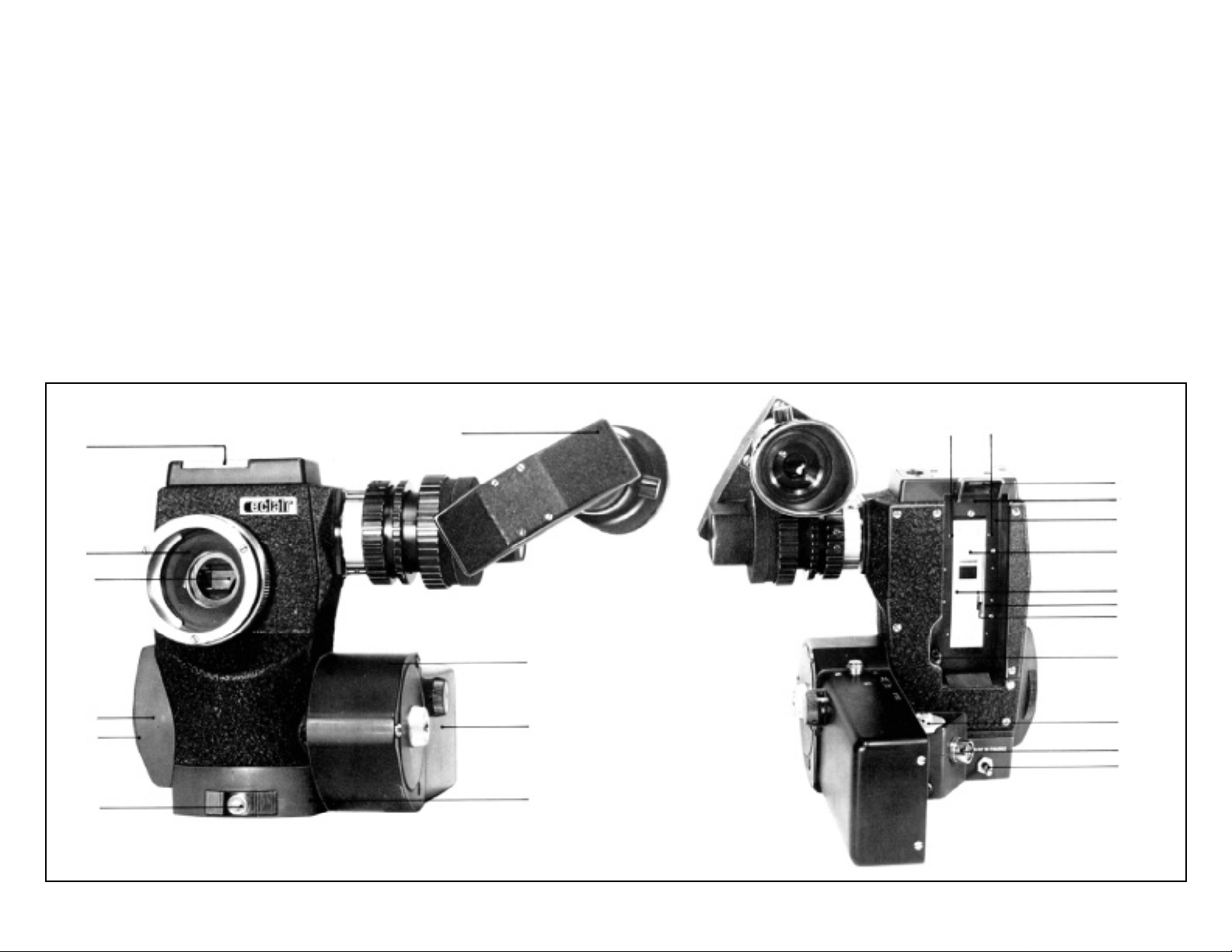
DESCRIPTION
THE CAMERA HEAD (Code MIPEX)
The camera head (Fig A) in special
aluminum alloy supports the lens mounts (1)
in stainless steel, the interchangeable gelatine-holder (2), the reflex viewfinder (3), the
motor (6) with its control for electronics (7),
the electronic base (8) incorporating the
sliding on/off switch (32), the lateral support
(75) of the hand-grip (36) with its micro-switch
(76), the magazine lock release lever (16)
with its safery catch (17) and the removable
hand-grip (36).
On the rear (Fig B): the mechanism
plate (9) on which are mounted film gate (10),
2
the fixed guide bar (11) and its side pressure bar
(12), the magazine drive shaft (18), the 4 pin
power supply socket (19) for connection with the
battery, the clapper switch (20) and the potentiometer (34) of the exposure indicator.
Inside: the claw mechanism (13), the
oscillating mirror (14), the plane shutter (15) and
the exposure indicator unit.
The snap-on 60m, or 120m magazine
are attached onto the camera head as well as
the fixed focal or zoom lenses.
3
NOTA. The above camera head can be supplied without Exposure indicator unit; its
commercial code is MITAN.
29
30
17
16
9
1
14
10
11
12
13
18
34
19
75
76
6
7
20
32
8
Fig. A
Camera head front view.
Viewfinder positioned
for the left eye.
Fig. B
Camera head rear view.
Viewfinder positioned
for the right eye.
4
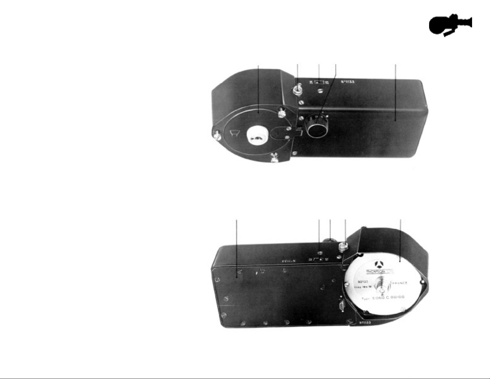
THE MULTIDUTY MOTOR (MIVAR)
This brushiess motor (6) has a very
high efficiency (from 0.8 to 1.2 amp. consumption at 12 volts to drive the camera at
20°C (68° F) and has permitted a weight
reduction not only in the camera but also in
the battery (37) - page 12 - which weighs only
640 grammes enabling one hour of filming
between recharges, i.e. eight to ten 60 m
magazines.
The incorporated electronics (7)
control the sync. speed by crystal ; changing
from 24 to 25 f.p.s. or vice-versa is made by
shifting switch (38) so that the white spot
mark is adjacent to the desired speed. Others
speeds : 8.12.50 and 75 are obtained by
setting the engraved button 35 accordingly.
The MIVAR will stop the camera
automatically in viewing position,
i.e. the mirror being in the aperture axis
allows the cameraman to frame and focus
without
loss of time. See pages 24 and 30.
The motor will only operate when it is
attached to the camera.
The lamp (47) on the motor lights up
until the marked speed is attained. In the
event of speed reduction (flat battery for
6
Fig. D. - Front part of the MIVAR.
7
47
38 35
38
35 47 6
7
Fig. E. - Rear part of the MIVAR.
5
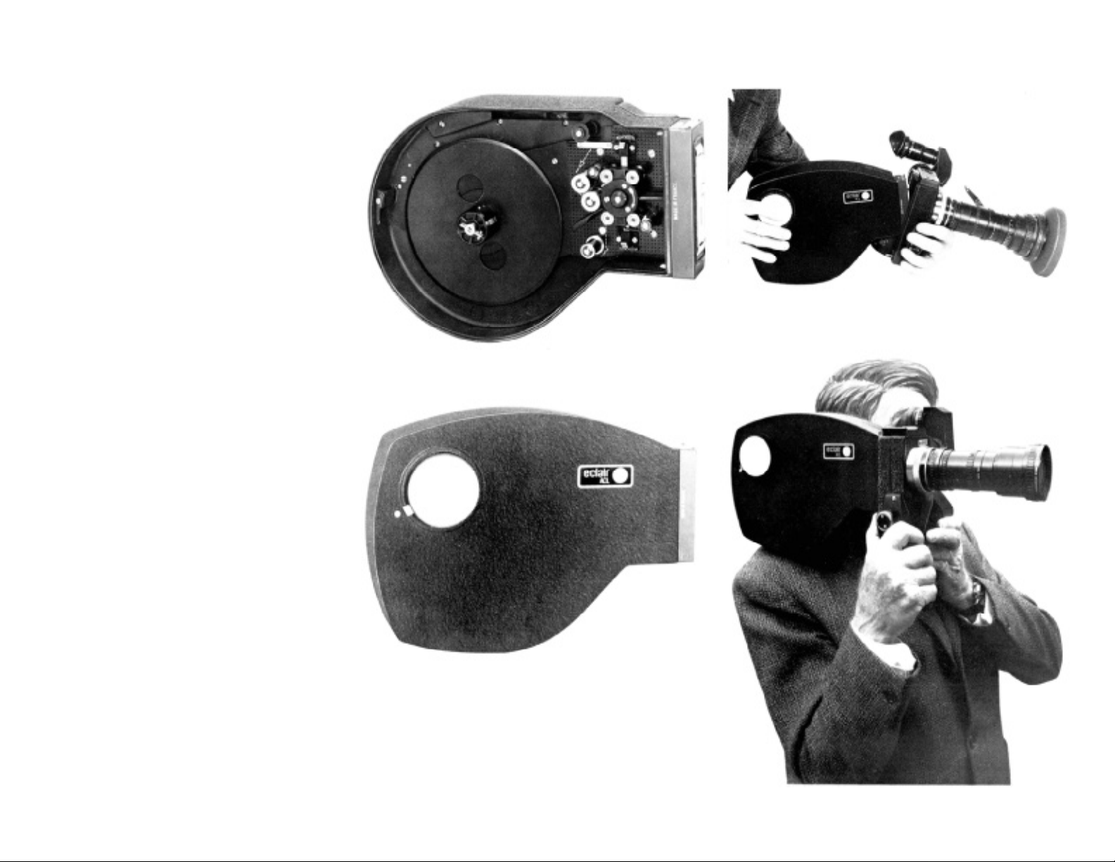
THE 60 m MAGAZI N E
The two chambers of this snap-on coaxial magazine are separated by a median
partition and are connected by a light tight
ramp for the passage of the film from the feed
side to the take-up side (Fig F).
THE 120 m MAGAZINE
Bearing in mind the versatility and light
weight of the 60 m magazine which can be
changed almost instantaneously, there are
occasions where a « long take » in excess of
60 m is required and for this purpose a 120 m
capacity magazine is available.
This co-axial magazine retains all the
characteristics of simple threading and snapon action for which the Eclair equipment is
famous.
Fig. G
Fig. F
Fig. H
Fig. I
6
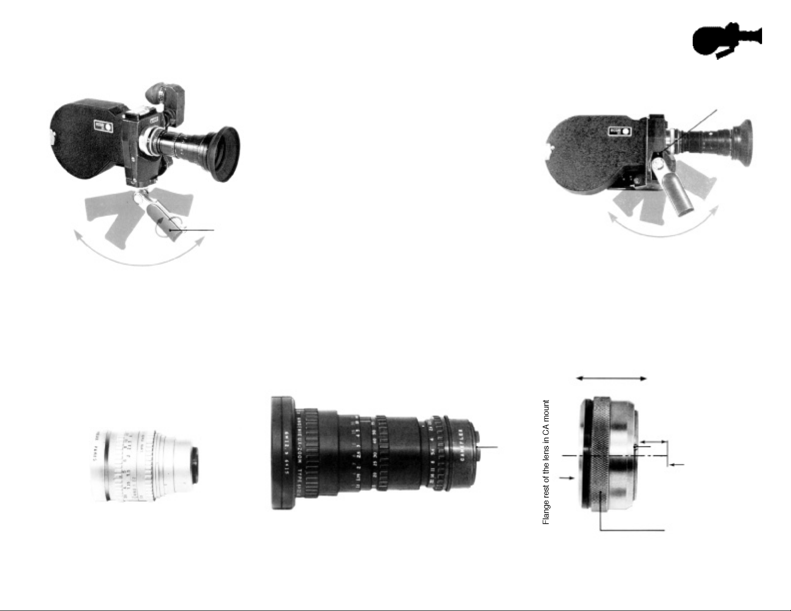
Fig. J
36
THE HAND-GRIP
The portability of the ACL is increased by
the use of the hand-grip (36) supplied with the
camera.
Adjustable in the horizontal and the
vertical plane, it permits the choice of the most
confortable position. It can be screwed either
under the camera base or on the right hand side
of the camera (fig K).
To carry the camera, the hand-grip (36)
with its knurled knob (79) - fig. QR - can also be
screwed on top of the camera head.
MOUNTS AND LENSES
The ACL has been designed to accept
« C » mount lenses (fig Q, the mechanical back
focal distance of which are 17.52 mm, and also
other professional mounts such as Eclair CA (fig
M) Arriflex, Nikon, etc... the mechanical back
focal distances of which are greater than 17.52
mm.
75
Fig. K
Fig. L
Lens in C mount
Fig. M
Lens in CA Eclair mount
26
48 mm
Ca mechanical back focal distance
C mechanical back focal distance
17.52 mm
24
Film plane
25
Fig. N
Intermediate mount
7
The mechanical back focal distances
(fig N) being different according to the professional equipment manufacturers 48 mm for
ECLAIR (Eclair CA), 52 mm for
Arriflex, 46 mm for Nikon, corresponding
intermediate Eclair TS mounts (Fig P-P’-P”-)
can be supplied for these different makes of
lenses for use with the ACL camera. For Arrif
lex, specify « normal mount » or « new steel
bayonet mount ».
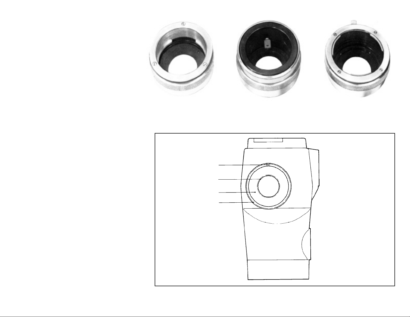
Hence, the ACL lens support (1)
comprises an internal threading (21) the
diameter and the thread pitch or which correspond to the C lenses standards and an
external threading (22) for the Eclair TS
mounts (Fig P-P’-P”); the orientation of the
lens is ensured by the slot (23) at tfie top of
the flange.
ACCESSORIES
The principal additional accessories of an
“ACL” equipment are :
• The 12 volts battery type VR 1,2
• The connection
cable camera/battery VR 1,2 .............
• The rapid charger ...............................
or
• 12 volts battery type VR 4 ..................
• The connection
cable Camera battery VR 4 ...............
• The compact charger .........................
• The connection
cable Charger/battery ........................
• The pilotone module ...........................
• The connection
cable Module/recorder
(according to the make of the recorder)
• The transport case ..............................
Code MIBAC
MIBLE
MIRAP
BAKEL
BABAC
CIBRE
COURE
MODUL
MALAC
Fig. P
Intermediate mount
for lenses in CA mount
23
21
22
Fig. O
Fig. P’
Intermediate mount
for lenses in Arriflex mount
Fig. P’’
Intermediate mount
for lenses in Nikon mount
1
8
GENERAL INFORMATION
REFLEX SIGHT
The reflex image is obtained with an
oscillating mirror (14) moving at half camera
speed, which transmits the image formed by
the lens onto the ground glass during the
descent of the film.
The viewf inder (focussing tube) is a
new mechanical /optical realization which
gives an exceptionally bright image.
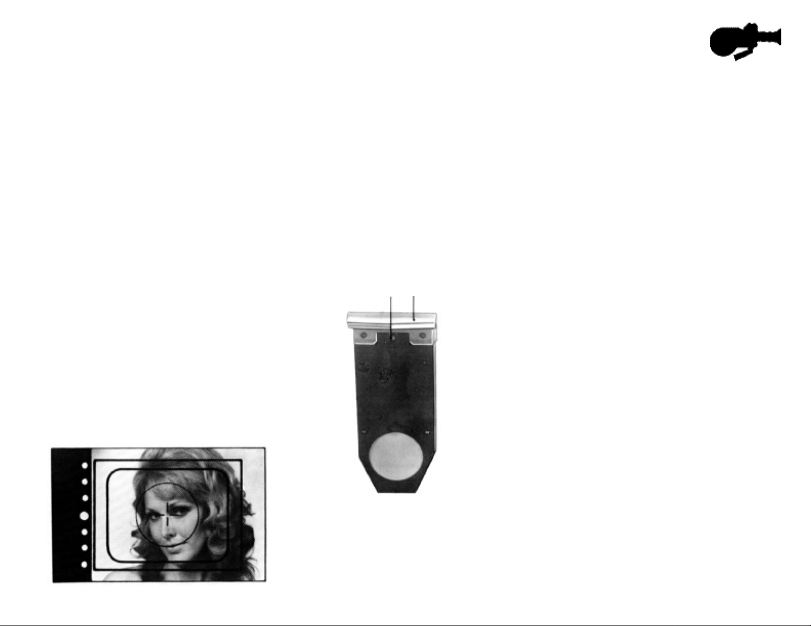
As on the Eclair 16, the ground glass
gives a field of view greater than the recorded
image, which eliminates the possible intrusion
of microphones, etc... into the recorded
picture. (Fig Q).
This viewfinder - 10 x enlargement can be used for left eye or right eye viewing it
can pivot through 360' parallel to the camera
thus allowing the cameraman to frame and to
focus in the most comfortable conditions
whatever the position of the camera; for
example, he can shoot with his back facing
the subject. The eyepiece is adjustable of ±
5dioptres.
The standard ground glass is engraved with the 16 mm frame (10,2
x 7,4 mm), the TV frame and a cross in the
centre (UER standard).
Gelatine filter holder
Each ACL is equipped with a gelatine
holder 2 (Fig A and R) which is located between
the C mount and the reflex mirror close to the
rear element of the taking lens. Its advantages
are :
• It is not necessary to change filter at each lens
change.
• It is possible to check the presence and type of
gelatine through the viewf inder.
• It eliminates the requirement for front glass
filters for each lens diameter, the price of which
is very high compared to that of gelatine filters
which are readily obtainable.
2
Fig. R
27
• Its position, away from the fi I m plane ensures any small dust or finger marks on the
gelatine that may occur are out of focus on the
final result and rarely visible.
Shutter
Contrary to reflex cameras in which the
mirror mounted at 45' acts as a shutter, the
ACL has a plane shutter of large diameter
completely independant of the mirror (14). It is
placed very close to the film plane with an
opening of 175'. Cutting the image in the
direction of the smallest dimension gives a
perfect exposure, maximum definition and
reduction of jerky effect on some panning
shots. The exposure time is 1 /51 of a second
at 25 frames per second and 1 / 49 of a second at 24 frames per second (page 33).
+
0
-
Fig. Q
9
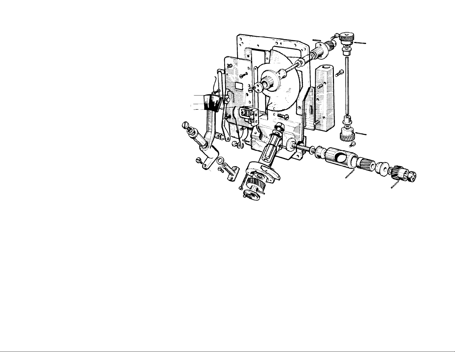
Mechanism
The complete silent mechanism is
mounted on the mechanism plate which
greatly reduces the time required for the
normal overhaul and cleaning which we
would strongly recommend to be carried out
by one of our agents.
The claw movement (13) is controlled
by an excentric and a fixed cam (39), the
security is ensured by a counter-cam.
The four drive shafts run in selflubrificated bearings and the camera mechanism should NEVER be oiled.
As already indicated page (4), the
aperture plate of hard chromium-plated steel
has, on the left, a fixed guide (11) which is the
edge reference for the film and a spring
loaded guide (12) on the right, which maintains the film against the fixed guide.
The two guides (29-30) fig B position
the magazine nose onto the mechanism
plate.
Fig. S
13
14
39
Exposure indicator
The ACL camera had to have a very
safe « Exposure Indicator device » because
of the professional work it must ensure. It
could not be question of an ordinary photocell system due to the fragility of moving
parts; on the other hand, a 100% automatic
device leaves the cameraman no change of
artistic creation.
The basic idea is to leave the cameraman freedom to determine the exposure of
the film and thus give him the possiblility of
working according to his own technique; in
other words he must have the possibility of
10
adjusting the diaphragm if he needs a special
effect by under or over exposure, e.g. contrast.
Before filming, the operator sets the
exposure indicator with the aid of his professional photo- cell exposure meter indicating the
diaphragm opening (stop) of the lens; it gives
him a reference lighting intensity « EO ». The
camera being connected to the battery, he
adjusts the sensitivity potentiometer (34) so that
only the middle diode EO, visible in the
viewfinder, lights up. Thus the camera is now
matched to the exposure meter.
During filming, if the lighting intensity of
the subject varies, the control diodes visible in
the viewf inder will be seen light up either + or . The operator wiII then correct the diaphragm
of his lens so as to maintain the lighting intensity on the film to a value of EO, if he deems it
necessary.
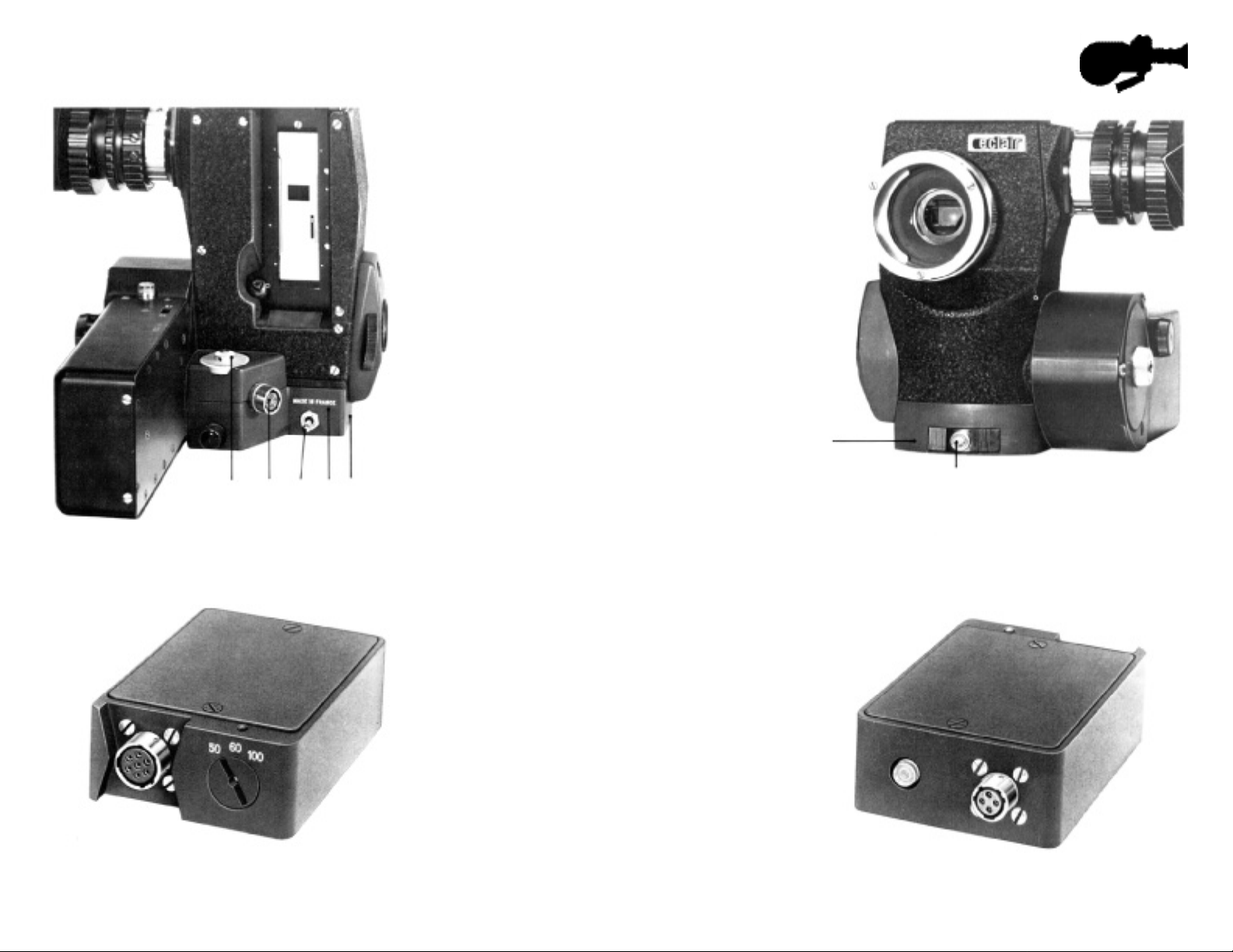
ELECTRONIC BASE 150 E
This unit (8) forms a flat base
for the camera body and consists of:
• 1 Jaeger socket (19) for power supply
to the camera.
• 1 Sliding on/off switch (32) at the front part.
• 1 Cannon socket (33) for the accessory
power supply.
• The stabilized 5 volt supply.
• 1 Souriau socket for electrical connections
with the camera head.
• 1 sensitivity potentiometer (34)
for adjustment of the exposure indicator.
• 1 Clapper switch (20).
This flat base is provided with the stan-
dard congress 3/8 tapped hole for tripod mounting or hand- grip mounting (36).
Fig. X
Magnetic recorder side
Fig. Y
34
19
20
PILOTONE MODULE
The ACL servo-control led crystal motor
33
8
allows the shooting of sync. sound without any
cable connection between the camera and the
tape recorder if the latter is equipped with a
crystal controlled motor (e.g. Nagra 4,
Perfectone E P 6 A2, Stellavox). Such a system
(diagram KL) does not permit the use of the
clapper.
If, however, the two units Camera and
recorder are connected by a cable, the clapper
will function (diagram L M). See additional
information page 29 for connection and use.
When the recorder has no crystal, the
synchronization can be ensured by using the
Eclair pilotone- module (option) which contains
its own signal.
THE ECLAIR PILOTONE MODULE is
contained in a metal cover. Its size: 92 x 66 x 23
mm is slightly larger than a packet of 20 cigarettes (fig. Y and Z). it is a crystal pilot f req
uency generator 50-60 and 100 H Z.
8
32
Fig. X’
Camera side
Fig. Z
11
Loading...