

Page 1

bear vac
MADE WITH PRIDE IN THE...
75050 - 5 HP HONDA PUSH
75060 - 6 HP INTEK PUSH
75350 - 5 HP HONDA 3 SPEED
75360 - 6 HP INTEK 3 SPEED
77060 - 6 HP KAWASAKI PUSH
77360 - 6 HP KAWASAKI 3 SPEED
owner's manual
PN: 13887-00S R0102
Companion to 13888-00S
Page 2

before You begin
MANUFACTURED BY CRARY INDUSTRIES
MANUFACTURED IN U.S.A.
XXXXXX
WEST FARGO, NORTH DAKOTA 58078 U.S.A.
SERIAL NUMBER
Dear crarY bear caT cusTomer
Thank you for purchasing a Crary Bear Cat product. The Crary Bear Cat line is designed, tested, and manufactured to give years of
dependable performance. To keep your machine operating at peak efciency, it is necessary to adjust it correctly and make regular
inspections. The following pages will assist you in the operation and maintenance of your machine. Please read and understand this
manual before operating your machine.
If you have any questions or comments about this manual, please call us toll-free at 1-800-247-7335.
If you have any questions or problems with your machine, please call or write your local authorized Crary Bear Cat Dealer.
This document is based on information available at the time of its publication. Crary Bear Cat is continually making improvements
and developing new equipment. In doing so, we reserve the right to make changes or add improvements to our product without
obligation for equipment previously sold.
Please senD us Your warranTY carD
A warranty card is included in your owner's kit packaged with your machine. Please take the time to ll in the information requested
on the card. When you send your completed card to us, we will register your machine and start your coverage under our limited
warranty.
ParTs orDerInG InFormaTIon
For service assistance or parts, contact your nearest authorized
Crary Bear Cat dealer or the factory. Your nearest authorized
dealer will need to know the serial number of your machine to
provide the most efcient service. See below for information on
how to identify and record the serial number for your machine.
if you need engine service or parts:
For engine service pr parts, contact your nearest authorized
engine dealer. An authorized engine dealer can handle all parts,
repairs, and warranty service concerning the engine.
serIal number locaTIon
Please record the serial number in the space provided and on
the warranty and registration card.
rePlacemenT ParTs
Only genuine Crary Bear Cat replacement parts should be used
to repair the machine. Replacement parts manufactured by oth-
ers could present safety hazards, even though they may t on
this machine. Replacement parts are available from your Crary
Bear Cat dealer.
Provide the following when ordering parts:
The SERIAL NUMBER of your machine.
The PART NUMBER of the part.
The PART DESCRIPTION.
The QUANTITY needed.
serIal number
How To conTacT crarY bear caT
address Phone e-mail hours
237 NW 12th Street
P.O. Box 849
West Fargo, ND 58078
800-247-7335
701-282-5520
FAX: 701-282-9522
opesales@crary.com
service@crary.com
© 2006, CRARY INDUSTRIES, ALL RIGHTS RESERVED. PRODUCED AND PRINTED IN THE U.S.A.
Monday - Friday,
8 am to 5 pm
Central Time
Page 3

LIMITED WARRANTY
This warranty applies to all AG and Outdoor Power Equipment manufactured by Crary Industries.
Crary Industries warrants to the original owner each new Crary Industries product to be free from defects
in material and workmanship, under normal use and service. The warranty shall extend 1 year from date of
delivery for income producing (commercial) applications and 2 years from date of delivery for non-income
producing (consumer) use of the product. The product is warranted to the original owner as evidenced by a
completed warranty registration on file at Crary Industries. Replacement parts are warranted for (90) days
from date of installation.
ThE WARRANTY REgIsTRATIoN MusT bE coMpLETED AND RETuRNED To cRARY INDusTRIEs
WIThIN 10 DAYs of DELIvERY of ThE pRoDucT To ThE oRIgINAL oWNER oR ThE WARRANTY
WILL bE voID.
In the event of a failure, return the product, at your cost, along with proof of purchase to the selling Crary
Industries dealer. Crary Industries will, at its option, repair or replace any parts found to be defective in material
or workmanship. Warranty on any repairs will not extend beyond the product warranty. Repair or attempted
repair by anyone other than a Crary Industries dealer as well as subsequent failure or damage that may occur
as a result of that work will not be paid under this warranty. Crary Industries does not warrant replacement
components not manufactured or sold by Crary Industries.
This warranty applies only to parts or components that are defective in material or workmanship.
1.
This warranty does not cover normal wear items including but not limited to bearings, belts, pulleys, filters
2.
and chipper knives.
This warranty does not cover normal maintenance, service or adjustments.
3.
This warranty does not cover depreciation or damage due to misuse, negligence, accident or improper
4.
maintenance.
This warranty does not cover damage due to improper setup, installation or adjustment.
5.
This warranty does not cover damage due to unauthorized modifications of the product.
6.
Engines are warranted by the respective engine manufacturer and are not covered by this warranty.
7.
Crary Industries is not liable for any property damage, personal injury or death resulting from the unauthorized
modification or alteration of a Crary product or from the owner’s failure to assemble, install, maintain or operate
the product in accordance with the provisions of the Owner’s manual.
Crary Industries is not liable for indirect, incidental or consequential damages or injuries including but not
limited to loss of crops, loss of profits, rental of substitute equipment or other commercial loss.
This warranty gives you specific legal rights. You may have other rights that may vary from area to area.
Crary Industries makes no warranties, representations or promises, expressed or implied as to the performance
of its products other than those set forth in this warranty. Neither the dealer nor any other person has any
authority to make any representations, warranties or promises on behalf of Crary Industries or to modify the
terms or limitations of this warranty in any way. Crary Industries, at its discretion, may periodically offer limited,
written enhancements to this warranty.
cRARY INDusTRIEs REsERvEs ThE RIghT To chANgE ThE DEsIgN AND/oR spEcIfIcATIoNs
of ITs pRoDucTs AT ANY TIME WIThouT obLIgATIoN To pREvIous puRchAsERs of ITs
pRoDucTs.
Page 4

Section Description Page
SAFETY ....................................................................................................................................1
BEFORE OPERA TING ................................................................................................................2
OPERA TION SAFETY .................................................................................................................2
MAINTENANCE AND STORAGE SAFETY..................................................................................2
SAFETY DECAL LOCA TIONS ..................................................................................................... 3
ASSEMBL Y ....................................................................................................................................4
ADDING MOTOR OIL TO ENGINE (ALL MODELS) ..................................................................... 4
ASSEMBL Y INSTRUCTIONS (ALL MODELS) ............................................................................. 5
FEA TURES AND CONTROLS............................................................................................................................ 6
DESCRIPTION OF OPERA TION .................................................................................................. 6
USE OF CONTROLS................................................................................................................... 7
OPERA TION ....................................................................................................................................9
FILLING THE T ANK ..................................................................................................................... 9
ST ARTING THE BEAR V AC.........................................................................................................9
STOPPING THE BEAR VAC ....................................................................................................... 9
ADJUSTING THE HANDLEBAR HEIGHT ................................................................................... 10
V ACUUMING GUIDE ................................................................................................................. 11
ATT ACHING AND EMPTYING THE BAG................................................................................... 12
SERVICE & MAINTENANCE............................................................................................................................ 13
MAINTENANCE SCHEDULE ..................................................................................................... 13
TIGHTENING THE BELT ............................................................................................................ 14
ADDITIONAL SERVICE AND MAINTENANCE TIPS .................................................................. 14
TROUBLESHOOTING .................................................................................................................................. 15
BOL T TORQUE REQUIREMENTS ................................................................................................................... 17
BearVac Operator’s ManualII
Page 5
INSERT
PRODUCT: Bear Vac
MODELS: All Models.
SUBJECT: Height Adjusting, Debris Bag,
New Handlebar Conguration, Handlebar
Height
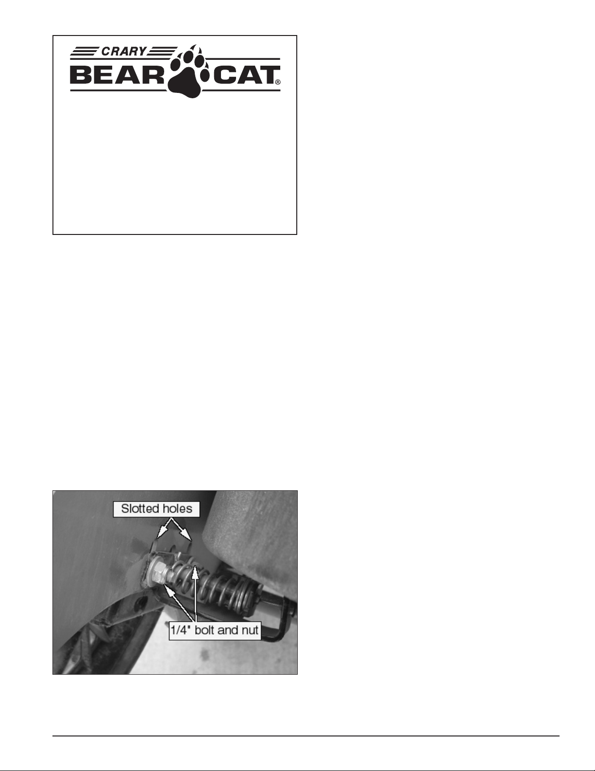
HEigHT aDJUSTing infORMaTiOn
The height of the nozzle can be set by adjusting the height adjust bracket. The bracket is located by the front wheel and is
mounted to the frame with (2) 1/4” carriage bolts. To adjust the
height of the nozzle slide the bracket in the slot to the desired
position.
DEBRiS Bag TiPS
The Bear Vac bag requires a break-in period to condition the
bag against premature blockage. During this time the debris bag
must be emptied frequently. The goal is to prevent dust from
becoming embedded in the bag. Embedded dust will cause
vacuum performance to suffer. To remove the dust remove the
bag from the machine, empty debris, and vigorously shake the
bag. If needed, the bag can be machine or pressure washed.
Thoroughly air dry the bag before use.
also:
- Do not leave debris in bag while in storage.
- Be sure to come to a complete stop before removing bag.
- Do not place the bag near hot surfaces, such as the engine.
To adjust:
Loosen the 1/4” nuts of the Bear Vac height adjust bracket.
1.
Make sure the bracket can slide on the frame.
Adjust the height of the Bear Vac nozzle to the desired posi-
2.
tion using the slotted holes. The recommended distance is
1/2” above ground level. In sandy conditions the nozzle can
be lowered further.
Once the position has been set tighten the bolts to a torque
3.
of 9 foot pounds.
Check the machine to ensure that it is level and at the proper
4.
height. Adjust if necessary using above procedure.
Fig. #1
Bear Vac Manual Insert
PN 74465-00 R0903
Page 6
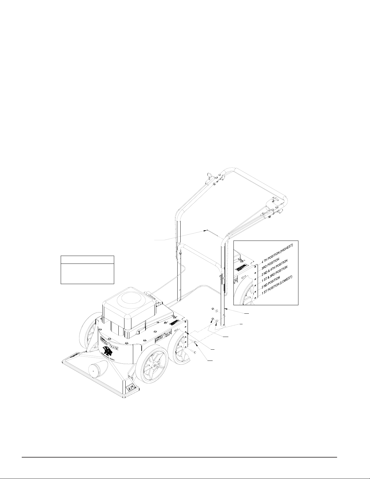
ATTACH TY-RAP
CLAMPS (QTY. 6) AFTER
DESIRED HANDLEBAR
HEIGHT IS ACHEIVED
The handlebars are shipped in
the lowest position. If desired
the handlebars can adjusted to
four different positions.
NOTE
5/16" X 1-3/4"
CARRIAGE BOLT
HANDLEBARS
ADJUSTMENT
HOLES
5/16" FLAT
WASHER
5/16" NYLOCK
LOCKNUT
nEw HanDLEBaR COnfigURaTiOn
The Bear Vac is now shipped with a upper handlebar connected to the lower handlebar. Both handlebars are connected to
the machine. Refer to the next section to adjust the handlebar
height.
aDJUSTing THE HanDLEBaR HEigHT
The handlebars of the Bear Vac can be mounted in four different
positions. The handlebar is shipped in its lowest position. If the
handlebar needs to be raised, follow the instructions below.
adjusting the handlebars:
Loosen the 5/16” bolts holding the lower handlebar onto the
1.
Bear Vac.
Remove the handlebar assembly from the frame of the
2.
Bear Vac.
Move the handlebar to the desired position on the frame.
3.
Reconnect the handlebar to the frame using the 5/16”
4.
hardware.
Bear Vac Manual Insert
Page 7
1
Safety
Section
THE SAFETY ALERT SYMBOL
This is the safety alert symbol. It is used in this Owner / Operator’s Manual and on your machine
to alert you to potential hazards.
Whenever you see this symbol, read and obey the safety message that follows it. Failure to obey
the safety message could result in personal injury, death or property damage
DANGER
WARNING
CAUTION
BEFORE OPERATING
1. Read this Owner / Operator’s
manual and the separate Engine
Owner’s manual carefully before
operating this equipment. Be completely familiar with the controls
and the proper use of this equipment.
2. Before inspecting or servicing any
part of the machine, stop engine,
wait for all parts to stop moving,
and disconnect spark plug wire.
Indicates an imminently hazardous situation that, if not avoided, will result in
death or serious injury.
Indicates a potentially hazardous situation that, if not avoided, could result in
death or serious injury.
Indicates a potentially hazardous situation that, if not avoided, may result in
minor or moderate injury.
4. Familiarize yourself with all of the
safety and operating decals on this
equipment and on any of it’s attachments or accessories.
5. Do not allow children or any person unfamiliar with the use of the
unit to use this machine.
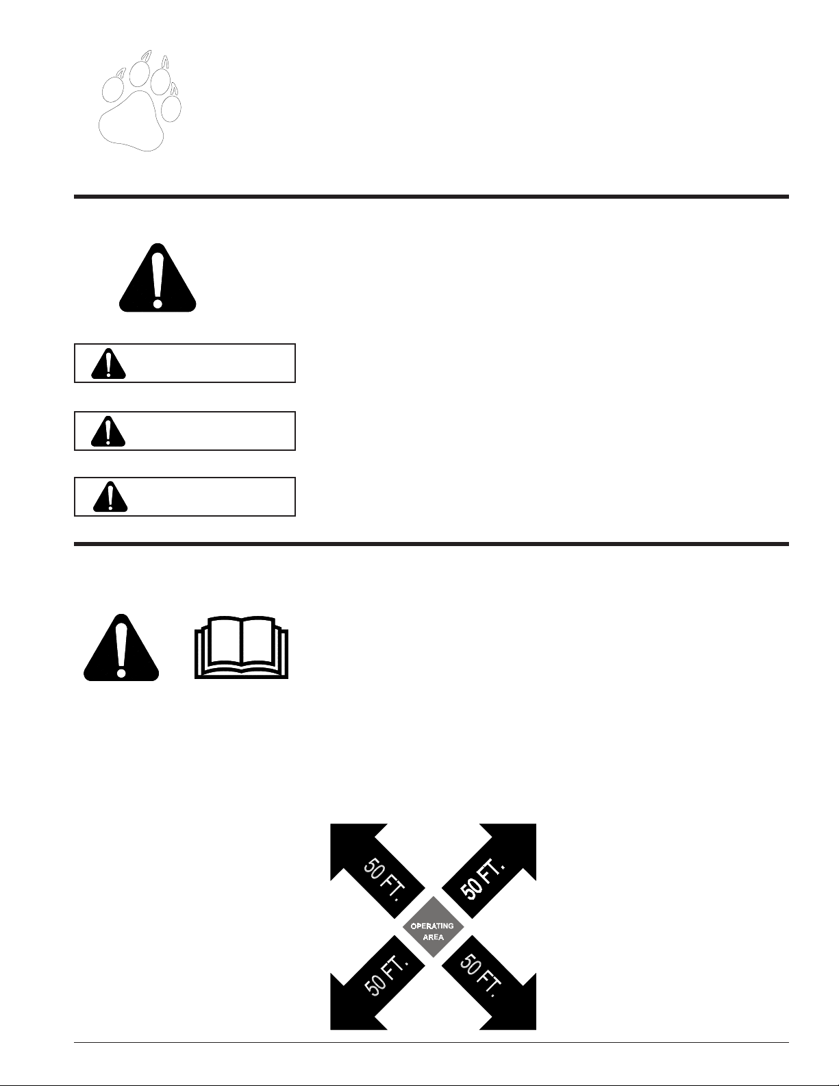
6. Keep the area of operation clear of
all persons, particularly small children. Keep bystanders at least
50 feet (15 meters) away from the
area of operation.
7. Do not run this equipment in an
enclosed area. Engine exhaust
contains carbon monoxide gas, a
deadly poison that is odorless,
colorless, and tasteless. Do not
operate this equipment in or near
buildings, windows, or air conditioners.
8. Always use an approved fuel container. Do not remove gas cap or
add fuel when engine is running.
Add fuel to a cool engine only.
9. Do not fill fuel tank indoors. Keep
open flames, sparks, smoking materials, and other sources of combustion away from fuel.
Be aware that rotating parts slow
down gradually after engine is shut
off.
3. Keep safety decals clean and legible. Replace missing or illegible
safety decals.
10. Do not operate this machine if you
are under the influence of alcohol,
medications, or substances that
can affect your vision, balance, or
judgement. Do not operate if tired
or ill. You must be in good health
to operate this machine safely.
Page 1Bear Vac Operator’s Manual
Page 8
Safety
BEFORE OPERATING
11. Use only in daylight or good artificial light.
12. Never use without proper guards
in place.
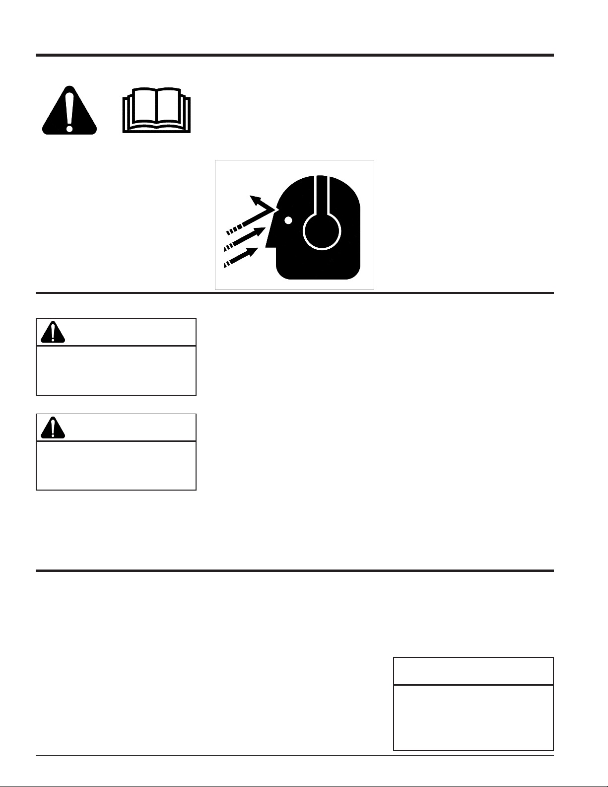
13. Wear safety glasses at all times
while operating this machine.
One pair of safety glasses is provided.
14. Wear ear protection at all times
OPERATION SAFETY
WARNING
Keep hands, feet and clothing out of
inlet opening while machine is operating to avoid personal injury.
WARNING
Wear eye, and hearing protection at
all times while operating the Bear
Vac.
while operating the Bear Vac.
14. Avoid wearing loose fitting clothing. Never operate this machine
wearing clothing with drawstrings that could wrap around
or get caught in the machine.
WRONG
1. Do not allow hands, or any part of
body or clothing near any moving
parts.
2. Shut off engine immediately if the
Bear Vac inhales any foreign object
or the machine starts vibrating. Allow the machine to stop completely.
After machine stops:
A. Shut off engine
B. Remove spark plug wire.
C. Inspect for damage.
D. Replace or repair any
damaged parts.
E. Check for and tighten any
loose parts.
3. Do not allow processed material to
build up in the discharge area; this
may prevent proper discharge and
can result in kickback of material
through the feed opening.
15. Check that all screws, nuts,
bolts, and other fasteners are
properly secured before starting
the machine. Check all screws,
nuts, bolts, and other fasteners
for proper tightness to ensure everything is in proper working condition once every 10 hours of operation.
16. Keep all guards, deflectors, and
shields in place and in good
working condition.
17. Do not transport or move machine while the machine is running.
4. Stand clear of the discharge area
when operating this machine.
5. Do not overreach. Keep proper bal-
ance and footing at all times.
6. Keep the engine clear of debris and
other accumulations.
7. Do not tamper with the engine gov-
ernor settings on the machine; the
governor controls the maximum safe
operating speed and protects the engine and all moving parts from damage caused by over speed.
8. Setting up your work site so you are
not endangering the public is critical for safety.
9. Shut off engine and allow machine
to stop completely before clearing
debris if the machine becomes
clogged.
MAINTENANCE AND STORAGE SAFETY
1. Shut off machine and disconnect the
spark plug wire when this equipment
is stopped for service, inspection,
storage, or to change an accessory.
2. Replace any missing or unreadable
safety decals. Refer to the parts
manual for part numbers when ordering safety decals from an area
Crary Bear Cat dealer.
3. Store the machine out of reach of
children and where fuel vapors will
Page 2 Bear Vac Operator’s Manual
not reach an open flame or spark.
Drain the fuel and dispose of it in a
safe manner for storage periods of
three months or more.
4. Allow machine to cool before storing in an enclosure.
5. Never store this machine with fuel
in the fuel tank inside a building
where fumes may reach an open
flame or spark, or where ignition
sources are present such as hot
water and space heaters, furnaces,
clothes dryers, stoves, electric motors etc.
NOTE
See engine owners manual or contact the engine manufacturer for
engine safety instructions and decals.
Page 9
Safety
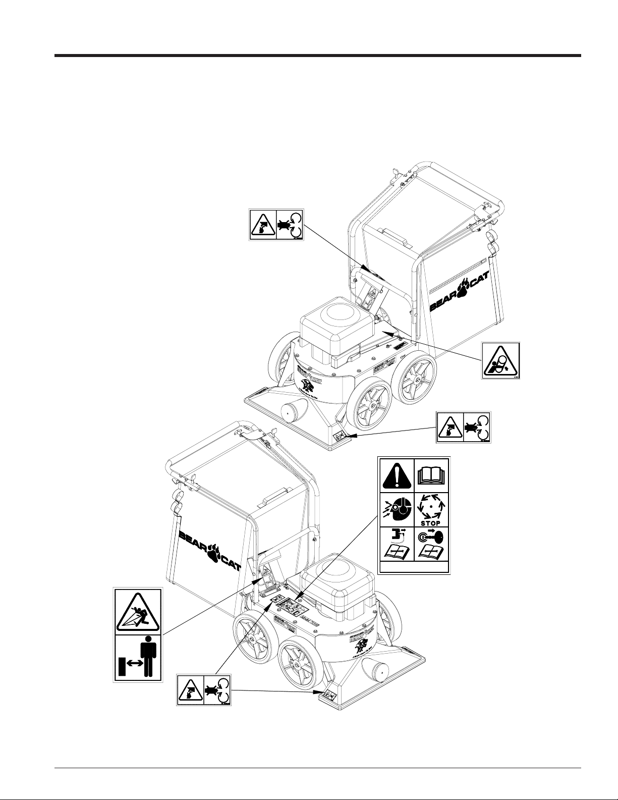
SAFETY DECAL LOCATIONS
Familiarize yourself with all of the safety and operational decals on the machine and the associated hazards. Make certain
that all safety decals and operational decals on this equipment are kept clean and in good condition. The decals are shown
below at reduced sizes. If you need a replacement decal, please refer to the parts catalog. Decals that need replacement
must be applied to their original locations.
P/N 13890-00
SAFETY DECAL IS UNDER GUARD
For replacement decals or operators manual, contact your Bearcat
dealer or Crary Co. P.O. Box 849 West Fargo, ND USA 58078-0849
P/N 12172
P/N 12174
P/N 13890-00
PN 12172
P/N 12252
P/N 13890-00
Fig. #1, Safety decal locations
Page 3Bear Vac Operator’s Manual
Page 10

2
Assembly
Section
Your Bear Vac may arrive totally or partially assembled. If your machine arrives partially assembled, you may need to
perform the steps in this section.
ADDING MOTOR OIL TO ENGINE (ALL MODELS)
IMPORTANT
Motor oil must be added
to the engine before it is
started.
1. The machine was shipped without
oil in the engine. Fill the engine
crankcase with the amount of oil
specified in the engine owners
manual.
2. To determine which type of oil to use,
refer to the engine owners manual
included in the owners kit of the Bear
Vac.
ASSEMBLY TORQUE CHART
UNIFIED INCH BOLT TORQUE VALUES (COARSE THREAD)
(unless otherwise specified in the manual)
Bolt
Diameter
"A"
1/4" 7.5 5.5 12 9 17 12.5
5/16”1511251835 26
3/8” 27 20 44 33 63 46
7/16” 44 32 70 52 100 75
1/2” 67 50 110 80 150 115
9/16” 95 70 155 115 225 160
5/8” 135 100 215 160 300 225
3/4” 240 175 375 280 550 400
7/8” 240 175 625 450 875 650
1” 360 270 925 675 1300 975
1-1/8” 510 375 1150 850 1850 1350
1-1/4” 725 530 1650 1200 2600 1950
1-3/8” 950 700 2150 1550 3400 2550
1-1/2” 1250 930 2850 2100 4550 3350
SAE 2
(N.m) (ft - lb) (N.m) (ft - lb) (N.m) (ft - lb)
Bolt Torque *
SAE 5 SAE 8
3. Remove the oil fill plug.
4. Checking as necessary, add oil to
the motor until the dipstick shows
the correct reading.
Page 4 Bear Vac Operator’s Manual
Page 11

ASSEMBLY INSTRUCTIONS (ALL MODELS)
Assembly
WARNING
To prevent personal injury or property damage: Shut off engine, disconnect spark plug wire, and make
sure that all moving parts have come
to a complete stop, before servicing, adjusting or repairing.
The Bear Vac is shipped with the upper handlebar draped over the front of
the machine.
Installing the handlebar:
1. Pick up the front handlebar and move
it to the rear of the machine.
2. Remove the 7/8” shipping caps on
the handlebar and discard.
3. Mount the upper handlebar to the
lower handlebar using the 5/16”
hardware provided in the owners kit.
4. Tighten bolts to proper torque.
5. Using ty-raps from the owners kit
secure the control cables to the machine.
BAG HANGER BRACKETS
Installing the bag:
1. Attach the the Bear Vac bag to
thebag handle/deflector.
2. Secure the bad to the bag handle/
deflector to the bag with the bag’s
strap.
3. Place the loops of the Bear Vac bag
into the bag hanger brackets.
4. Lift the exhaust door.
5. Attach the bag handle/deflector to
the fan housing of the Bear Vac.
TY-RAP
CLAMP
RAISE EXHAUST DOOR
ATTACH BAG HANDLE
/ DEFLECTOR
BEARVAC BAG
BAG HANDLE / DEFLECTOR
5/16" X 1-3/4"
CARRIAGE BOLT
NOTE: FOR SHIPPPING PURPOSES
ONLY, CAP CAN BE DISCARDED.
5/16" FLAT
WASHER
5/16" NYLOCK
LOCKNUT
Fig. #2, Assembly instructions
Page 5Bear Vac Operator’s Manual
Page 12

Features & Controls
g
FEATURES AND CONTROLS IDENTIFICATION
Learn the location of the features and controls on your machine before operating.
All Models
CLUTCH CONTROL
THROTTLE ASSEMBLY
EXHAUST DOOR
BAIL
HANDLEBARS
HEIGHT ADJUSTMENT
CONTROL
GEAR SHIFT CONTROL
VENTILATION OPENING
BEARVAC COLLECTION
BAG
BAG HANDLE / DEFLECTOR
TRANSMISSION
NOTE
All references to left, right, front,
and rear of the machine are determined by standing behind the
handlebars and facin
ion of forward travel.
the direct-
ENGINE
FAN HOUSING
INTAKE FOR OPTIONAL
HOSE KIT
FAN INTAKE HOUSING
Fig #3, Parts shown are not included on all models
DESCRIPTION OF OPERATION
Understanding how your machine works will help you achieve the best results when using your Bear Vac.
The Bear Vac vacuums in debris through the nozzle of the machine or the optional hose. The debris travels through the
length of the Bear Vac housing, and into the Bear Vac bag. The bag of debris is then dumped as needed.
Page 6 Bear Vac Operator’s Manual
Page 13

USE OF CONTROLS
Features & Controls
Model # 75050, 75060.
WARNING
To prevent personal injury or property damage: Shut off engine, disconnect spark plug wire, and make
sure that all moving parts have come
to a complete stop, before servicing, adjusting or repairing.
1. Engine Throttle: Changes engine
speed, turns the engine on and off,
and places the engine in choke on
the Honda engines. On Briggs
models the choke is not located
on the throttle (See Briggs owners
manual).
2. Height adjustment control: The
Bear Vac nozzle height is adjustable. Adjust the height as needed
to optimize vacuuming performance.
3. Recoil start: Bear Vacs are all
equipped with a recoil starter. To
start the engine with the recoil
starter follow starting instruction in
the operation section of the manual.
Model # 75350, 75360.
WARNING
To prevent personal injury or property damage: Shut off engine, disconnect spark plug wire, and make
sure that all moving parts have come
to a complete stop, before servicing, adjusting or repairing.
1. Engine Throttle: Changes engine
speed, turns the engine on and off,
and places the engine in choke on
the Honda engines. On Briggs
models the choke and is not located on the throttle (See Briggs
owners manual).
2. Height adjustment control: The Bear
Vac nozzle height is adjustable. Adjust the height as needed to optimize vacuuming performance.
3. Transmission shift control: This
control shifts the self-propelled
transmission between three gears.
Do not shift the machine with the
transmission turning.
4. Clutch bail: This control engages
the transmission to drive the Bear
Vac forward. Release the bail when
shifting the transmission.
3. Recoil start: Bear Vacs are all
equipped with a recoil starter. To
start the engine with the recoil
starter follow starting instruction in
the operation section of the manual.
Fig. #4, Throttle Fig. # 5, Height adjustment control
Page 7Bear Vac Operator’s Manual
Page 14

4
Operation
Section
WARNING
Before operating your machine, be
sure you read and understand all
safety, controls and operating instructions in this Owner/Operators
manual and on your machine.
Failure to follow these instructions
can result in serious injury or property damage.
As with any other piece of outdoor
power equipment, getting the “feel” for
how your machine operates and getting
to know the best techniques for
particular jobs are important to overall
good performance.
Read this section thoroughly before you
start the engine. The instructions given
here will help you become familiar with
your machine and have you operating
efficiently in a short time.
This section covers:
• Filling the tank
• Starting the machine
• Stopping the machine
• Adjusting handlebar height
• Engaging self propelled units
• Vacuuming
• Emptying the bag
• Optional equipment
Fig. #6, Bear Vac in action
Page 8 Bear Vac Operator’s Manual
Page 15

Operation
FILLING THE TANK
DANGER
Gasoline is highly flammable
and its vapors are explosive. To
prevent personal injury or property damage:
Store gasoline only in approved
containers, in well ventilated, unoccupied buildings, away from sparks
or flames. Do not fill the fuel tank
while the engine is hot or running,
since spilled fuel could ignite if it
comes in contact with hot parts or
sparks from ignition. Do not start
the engine near spilled fuel. Never
use gasoline as a cleaning agent.
FILLING THE FUEL TANK
Fuel Type:
For best results use only clean, fresh,
unleaded gasoline with a pump sticker
octane rating of 87 or higher. In countries using the Research method, it
should be 90 octane minimum.
Purchase gasoline in small quantities
and store in clean, approved containers. A container with a capacity of 2
gallons or less with a pouring spout is
recommended. Such a container is
easier to handle and helps eliminate
spillage during refueling. DO NOT MIX
OIL WITH GASOLINE.
Gasoline Alcohol blends
Gasohol (up to 10% ethyl alcohol, 90%
unleaded gasoline by volume) is approved as a fuel for Briggs and Honda
engines. Other gasoline/alcohol blends
are not approved.
Gasoline Ether blends
Methyl Tertiary Butyl Ether (MTBE) and
unleaded gasoline blends (up to a maximum of 15% MTBE by volume) are
approved as a fuel for Briggs and Honda
engines. Other gasoline/ether blends
are not approved.
To Add Gasoline.
1. Stop engine, wait for all parts to stop
moving, and disconnect spark plug
wire. Allow the engine and muffler
to cool for at least three minutes.
2. Clean area around fuel fill cap and
remove cap.
3. Using a clean funnel, fill fuel tank to
1/2” below bottom of filler neck to
provide space for any fuel expansion. Install fuel fill cap securely and
wipe up any spilled gasoline.
STARTING THE BEAR VAC
Move machine to a clear, level
area outdoors before starting. Do
not operate in the vicinity of bystanders. Make sure the chamber
is empty before starting. Also, do
not engage the bail while starting
self propelled models.
1. Reference the Briggs and Stratton
and Honda Owners Manuals.
2. Check engine oil level before starting.
3. Place the throttle control on Honda
4. On Briggand Stratton engines prime
5. Pull the recoil starter until the en-
STOPPING THE BEAR VAC
WARNING
Allow the machine to come to complete
stop before inspection or servicing.
engines into the run or choke position, depending upon engine temperature.
the engine three times, depending
upon temperature.
gine starts. Make sure the starting
cord retracts.
1. Reference the Briggs and Stratton and Honda Owners Manuals.
2. Move the throttle to the “slow” or “low” idle position.
3. Allow the engine to run at idle for 30-60 seconds; then stop the
engine by moving the throttle to the off position.
6. Move throttle to the desired position.
7. For a Cold Engine — Gradually
return the throttle control from the
choke position to the run position
as the engine warms up.
4. Allow machine to come to a complete stop.
Page 9Bear Vac Operator’s Manual
Page 16

p
j
p
Operation
ADJUSTING THE HANDLEBAR HEIGHT
The handlebars of the Bear Vac can
be mounted in four different positions.
The handlebar is shipped in its lowest
position. If the handlebar needs to be
raised, follow the instructions below.
Adjusting the handlebars:
1. Loosen the 5/16” bolts holding the
lower handlebar onto the Bear Vac.
2. Remove the handlebar assembly
from the frame of the Bear Vac.
3. Move the handlebar to the desired
position on the frame.
4. Reconnect the handlebar to the
frame using the 5/16” hardware.
NOTE
The handlebars are shipped in
the lowest
the handlebars can ad
four different
osition. If desired
usted to
ositions.
ATTACH TY-RAP
CLAMPS (QTY. 6) AFTER
DESIRED HANDLEBAR
HEIGHT IS ACHEIVED
HANDLEBARS
5/16" FLAT
WASHER
5/16" NYLOCK
LOCKNUT
ADJUSTMENT
HOLES
5/16" X 1-3/4"
CARRIAGE BOLT
Fig. #7, Handlebar Adjustment
Page 10 Bear Vac Operator’s Manual
Page 17

VACUUMING GUIDE
NOTE
Please read and follow all
safety instructions in this
manual. Failure to operate the
Bear Vac in accordance with
the safety instructions MAY RESULT IN PERSONAL INJURY!
IMPORTANT
Exclude pieces of metal, rocks,
bottles, and other foreign objects
when vacuuming.
Operating tips:
1. Avoid overfilling the vacuum nozzle.
This can lead to clogging, especially
if the material is wet and soggy.
Operation
2. Work from the outer edge of leaf
piles and gradually move inward with
the vacuum.
3. Before leaves fall, mow the lawn to
a shorter length to aid in vacuuming.
4. Check and empty the collection bag
frequently.
5. Avoid vacuuming twigs and sticks
that are likely to clog the vacuum
nozzle.
6. Use slower ground speeds if the materials vacuumed are wet or heavy.
7. Typically the Bear Vac works best
when operated at full throttle.
Fig. #8, Bear Vac vacuuming
Adjusting the height of the nozzle:
The nozzle can be adjusted between 5
settings. The height of the Bear Vac
nozzle can be adjusted by pulling the
height adjustment cable, adjusting the
Bear Vac to the desired position, and
releasing the height adjustment cable
to lock the Bear Vac in position.
Engaging self-propelled Bear Vacs:
The self propelled Bear Vac vacuums
are engaged with the clutch engagement bail located under the handlebar.
When the bail is brought up to the bar
the clutch is engaged and the machine
moves forward. When the bail is released the speed of the machine can
be adjusted between three settings
using the transmission shift control located on the left of the handlebar.
Page 11Bear Vac Operator’s Manual
Page 18

Operation
ATTACHING AND EMPTYING THE BAG
Emptying the bag:
1. Remove the bag handle/deflector
from the Bear Vac bag by lifting on
the handle (See fig. #9). The spring
loaded exhaust shield door will
close.
2. Remove the two loops of the Bear
Vac bag from the bag hanger brackets (See fig. #10).
3. The bag is removed from the machine.
4. Open the main zipper.
5. Remove the debris from the inside
of the bag to a larger container or
compose pile.
6. Close the zipper, being aware not to
let debris become lodged in the zipper teeth.
Attaching the bag:
1. Place the loops of the Bear Vac bag
into the bag hanger brackets.
2. Lift the exhaust door.
3. Attach the bag handle/deflector to
the fan housing of the Bear Vac.
Notes:
• Use bag at all times.
• Empty bag before it fills completely.
A full bag will cause performance to
decrease or stop completely.
Fig. #9, bag handle deflector (Shown with optional hose kit)
• Empty bag completely before storage.
• Keep bag clean by occasionally
washing it with mild soap and water. Do not wash in an automatic
washer.
Fig. #10, Removing bag straps from bag hanger brackets
Page 12 Bear Vac Operator’s Manual
Page 19

5
Service & Maintenance
Section
WARNING
To prevent personal injury or property damage: Shut
off engine, disconnect spark plug wire, and make sure
that all moving parts have come to a complete stop
before, servicing, adjusting or repairing.
SERVICE AND MAINTENANCE SCHEDULE
MAINTENANCE SCHEDULE
The following items listed in the service and maintenance
schedule are to be checked, and if necessary, corrective
action should be taken. This schedule is designed for units
operating under normal conditions. If the unit is operating in
adverse or severe usage conditions it may be necessary for
the items to checked and serviced more frequently.
See engine owners manual for further maintenance and
troubleshooting information.
FREQUENCY
COMPONENT
ENGINE OIL C HECK OIL LEVE L
FUEL TANK FILL
AIR CLEANER CHECK AND CLEAN¹
AIR INTAKE CLEAN¹
ENGINE OIL CHA NGE
FUEL FILTER REPLACE
SPARK PLUG
NUTS AND BOLTS CHECK
BEL T C ONDITION C HEC K
CHAIN LUBE
BELT TENSION CHECK
ENTIRE MACHINE CLEAN
MAINTENANCE
REQUIRED
CHECK CONDTION
AND GAP
Refer to Engine
Operator manual
•
BEFORE
EACH
USE
EVERY
8
HOURS
EVERY
25
HOURS
EVERY
50
HOURS
•
EVERY
100
HOURS
EVERY
200
HOURS
EVERY
500
HOURS
Page 13Bear Vac Operator’s Manual
Page 20

TIGHTENING THE BELT(SELF PROPELLED MODELS ONLY)
Service & Maintenance
Check the condition of the drive belts annually or every 25
hours of operation, whichever comes first. Check also to
make sure the belt is tightened to the proper tension. To
tighten belt:
1. Take off the belt guard by removing the 11/32” hardware.
2. Loosen the three 1/4” adjustment bolts connected to the
Bear Vac transmission.
3. Loosen the 1/4 bolts on the side of the machine connected to the 1/2” flange bearing.
4. With the five bolts loosened the belt is free to move.
5. Tighten the belt to the desired position (1/4” of deflection)
and by moving the transmission towards the rear of theunit.
Retighten all loosened bolts to proper torque.
6. The chain will need to be readjusted after the belt is tightened due to movement of the 1/2” bearing flange.
7. Tighten the chain by first loosening the four 1/4” bolts on
both sides of the axle assembly.
11/32" X 7/8"
BELT GUARD
WHEEL REMOVED
FOR CLARITY ONLY
Fig. #11, Adjusting the belt
SCREW
LOOSEN
BOLTS
DRIVE
PULLY
1/4" TO 1/2"
DEFLECTION
IS ACCEPTABLE
DRIVEN
PULLEY
LOOSEN
LOOSEN
BOLTS
DRIVE
BELT AND CHAIN
TENSION
8. After the bolts are loosened the axle is free to be lowered.
Lower the axle until the chain has 1/4” of deflection.
DRIVE BELT
9. Retighten the four 1/4” bolts to torque.
DRIVE CHAIN
10. Recheck the tension on the belt. Repeat procedure if
necessary.
NOTE: FOR SELF PROPELLED MODELS ONLY
11. Replace the belt guard on the machine and secure with
11/32” hardware.
ADDITIONAL SERVICE AND MAINTENANCE TIPS
1. Service engine according to engine owners manual.
2. Every 10 hours of operation, all bolts and other fasteners
should be checked for correct torque.
Fig. #12, Checking belt tension
Page 14 Bear Vac Operator’s Manual
Page 21

Service & Maintenance
g
g
g
g
g
g
gg
g
g
g
g
g
g
g
TROUBLESHOOTING
Before performing any of the correction in this troubleshooting chart, refer to the appropriate information contained in this
manual for the correct safety precautions and operating or maintenance procedures. Contact your nearest dealer or the
factory for service problems with the machine.
PROBLEM POSSIBLE CAUSE REMEDY
1. Engine will not start. 1. Improper control settings. 1. Use proper setting.
2. Lack of fuel. 2. Fill fuel tank.
3. Internal En
4. Spark plu
5. Dirty stale or contaminated
2. En
ine or rotor stalls or stops. 1. Obstructed discharge. 1. Use branch or similar object to clear
2. Plu
ine overheats. 1. Improper oil level. 1. Fill engine to the correct oil level. Refer
3. En
4. Excessive vibration while runnin
. 1. Drive system vibration. 1. Check rotor, belts, and pulleys for bad
ine Problems. 3. See your dealer.
disconnected. 4. Connect spark plug.
as. 5. Refill gas tank with fresh, clean
unleaded re
dischar
ed Rotor. 2. Clear Rotor.
to en
or worn areas.
ular gasoline.
e.
ine owners manual.
5. Excessive belt wear. 1. Not usin
2. Pulley(s) dama
3. Pulley(s) not in ali
4. Belt(s) tension too loose. 4. Ti
correct belt. 1. Contact your nearest authorized dealer
to order the correct belt for your Bear Vac.
ed or wore. 2. Replace pulley(s).
nment. 3. Align pulley(s) with straight edge.
hten belt(s) or replace.
Page 15Bear Vac Operator’s Manual
Page 22

Bear Vac Specifications
Specifications
27.00
38.27
LOWEST
HANDLEBAR
SETTING
24.08
Fig. #13, Specifications
SPECIFICATIONS
MODEL 75050 75060 75350 75360
INTAKE WIDTH 27" 27" 27" 27"
TIRE SIZE 12" X 2.5" 12" X 2.5" 12" X 2.5" 12" X 2.5"
ROTOR CONSTRUCTION 1/4" STEEL BLADES 1/4" STEEL BLADES 1/4" STEEL BLADES 1/4" STEEL BLADES
SELF PROPELLED NO NO YES - 3 SPEEDS YES - 3 SPEEDS
WEIGHT 108 LBS. 113 LBS 121 LBS 126 LBS
ENGINE HONDA 5 HP OHV B & S 6 HP INTEK OHV HONDA 5 HP OHV B & S 6 HP INTEK OHV
Page 16 Bear Vac Operator’s Manual
Page 23

Specifications
BOLT TORQUE REQUIREMENTS
The tables shown below give correct torque values for various bolts and capscrews. Tighten all bolts to the torques specified
in chart unless otherwise noted. Check tightness of bolts periodically, using this bolt torque chart as a guide. Fasteners
should be replaced with the same grade. Tighten serrated or center-lock nuts to the full torque value.
Do not use these values if a different torque value or tightening procedure is given for a specific application. Torque values
listed are for general use only.
SAE
Grade
and
Head
Markings
SAE - 8SAE - 2ASAE - 5
BOLT DIAMETER
UNIFIED INCH BOLT TORQUE VALUES (COARSE THREAD)
(unless otherwise specified in the manual)
Bolt
Diameter
"A"
1/4" 7.5 5.5 12 9 17 12.5
5/16”1511251835 26
3/8” 27 20 44 33 63 46
7/16” 44 32 70 52 100 75
1/2” 67 50 110 80 150 115
9/16” 95 70 155 115 225 160
5/8” 135 100 215 160 300 225
3/4” 240 175 375 280 550 400
7/8” 240 175 625 450 875 650
1” 360 270 925 675 1300 975
1-1/8” 510 375 1150 850 1850 1350
1-1/4” 725 530 1650 1200 2600 1950
1-3/8” 950 700 2150 1550 3400 2550
1-1/2” 1250 930 2850 2100 4550 3350
SAE 2
(N.m) (ft - lb) (N.m) (ft - lb) (N.m) (ft - lb)
Bolt Torque *
SAE 5 SAE 8
Torque figures indicated at left are
valid for non-greased or non-oiled
threads and heads unless otherwise specified. Therefore, do not
grease or oil bolts or capscrews
unless otherwise specified in this
manual. When using locking elements, increase torque values by
5%.
* Torque value for bolts and
capscrews are identified by their
head markings.
Page 17Bear Vac Operator’s Manual
Page 24

Declaration of Conformity
The undersigned manufacturer:
Crary Industries, Inc.
237 NW 12
P.O. Box 849
West Fargo, ND 58078-0849
Declares that hereunder specified:
WALK BEHIND VACUUM
Brand: Crary Bear Cat
Type: Engine driven Walk Behind Vacuum
Model Numbers: 77060S
Complies with the requirements of:
Machinery Directive 2006/42/EC
Emission of Gaseous and Particulate Pollutants Directive 2002/88/EC
Noise Emissions Directive 2000/14/EC
-Conformity Assessment Procedure: Annex V
(Use of harmonized standard EN ISO 3744:2010)
Sound Power Level: 84 dB L
Guaranteed Sound Power Level: 98 dB LWA
77060S Serial number 602202 and up
West Fargo, ND 58078-0849
June 29, 2011
CRARY INDUSTRIES, INC. The authorized representative in Europe who is authorized to
compile the technical file:
Company: Atlantic Bridge Limited
Address: Atlantic House, PO Box 4800
Earley, Reading RG5 4GB, United Kingdom
______________________________
Arlan Mathias Mr. Phillip Wicks
Senior Project Engineer
PA
th
Street
Data contained in this document pertains only to machines sold in areas that require CE compliance
standards. To identify if your machine is CE compliant, it will have the following CE mark decal:
Page 25

Declaration of Conformity
The undersigned manufacturer:
Crary Industries, Inc.
237 NW 12
P.O. Box 849
West Fargo, ND 58078-0849
Declares that hereunder specified:
WALK BEHIND VACUUM
Brand: Crary Bear Cat
Type: Engine driven Walk Behind Vacuum
Model Numbers: 75360S
Complies with the requirements of:
Machinery Directive 2006/42/EC
Emission of Gaseous and Particulate Pollutants Directive 2002/88/EC
Noise Emissions Directive 2000/14/EC
-Conformity Assessment Procedure: Annex V
(Use of harmonized standard EN ISO 3744:2010)
Sound Power Level: 84 dB L
Guaranteed Sound Power Level: 98 dB LWA
75360S Serial number 101908 thru 709647
West Fargo, ND 58078-0849
June 29, 2011
CRARY INDUSTRIES, INC. The authorized representative in Europe who is authorized to
compile the technical file:
Company: Atlantic Bridge Limited
Address: Atlantic House, PO Box 4800
Earley, Reading RG5 4GB, United Kingdom
______________________________
Arlan Mathias Mr. Phillip Wicks
Senior Project Engineer
PA
th
Street
Data contained in this document pertains only to machines sold in areas that require CE compliance
standards. To identify if your machine is CE compliant, it will have the following CE mark decal:
Page 26

Declaration of Conformity
The undersigned manufacturer:
Crary Industries, Inc.
237 NW 12
P.O. Box 849
West Fargo, ND 58078-0849
Declares that hereunder specified:
WALK BEHIND VACUUM
Brand: Crary Bear Cat
Type: Engine driven Walk Behind Vacuum
Model Numbers: 75060S
Complies with the requirements of:
Machinery Directive 2006/42/EC
Emission of Gaseous and Particulate Pollutants Directive 2002/88/EC
Noise Emissions Directive 2000/14/EC
-Conformity Assessment Procedure: Annex V
(Use of harmonized standard EN ISO 3744:2010)
Sound Power Level: 84 dB L
Guaranteed Sound Power Level: 98 dB LWA
75060S Serial number 101907 and up
West Fargo, ND 58078-0849
June 29, 2011
CRARY INDUSTRIES, INC. The authorized representative in Europe who is authorized to
compile the technical file:
Company: Atlantic Bridge Limited
Address: Atlantic House, PO Box 4800
Earley, Reading RG5 4GB, United Kingdom
______________________________
Arlan Mathias Mr. Phillip Wicks
Senior Project Engineer
PA
th
Street
Data contained in this document pertains only to machines sold in areas that require CE compliance
standards. To identify if your machine is CE compliant, it will have the following CE mark decal:
Page 27

Declaration of Conformity
The undersigned manufacturer:
Crary Industries, Inc.
237 NW 12
P.O. Box 849
West Fargo, ND 58078-0849
Declares that hereunder specified:
WALK BEHIND VACUUM
Brand: Crary Bear Cat
Type: Engine driven Walk Behind Vacuum
Model Numbers: 77360S
Complies with the requirements of:
Machinery Directive 2006/42/EC
Emission of Gaseous and Particulate Pollutants Directive 2002/88/EC
Noise Emissions Directive 2000/14/EC
-Conformity Assessment Procedure: Annex V
(Use of harmonized standard EN ISO 3744:2010)
Sound Power Level: 84 dB L
Guaranteed Sound Power Level: 98 dB LWA
77360S Serial number 602203 and up
West Fargo, ND 58078-0849
June 29, 2011
CRARY INDUSTRIES, INC. The authorized representative in Europe who is authorized to
compile the technical file:
Company: Atlantic Bridge Limited
Address: Atlantic House, PO Box 4800
Earley, Reading RG5 4GB, United Kingdom
______________________________
Arlan Mathias Mr. Phillip Wicks
Senior Project Engineer
PA
th
Street
Data contained in this document pertains only to machines sold in areas that require CE compliance
standards. To identify if your machine is CE compliant, it will have the following CE mark decal:
Page 28

crary bear cat
237 NW 12th Street, West Fargo, ND 58078-0849
Phone: 701.282.5520 • Toll free: 800.247.7335
fax: 701.282.9522 •
e-mail: service@crary.com • opesales@crary.com
www.bearcatProducts.com
 Loading...