

Page 1
OWNER
OPERATORS
MANUAL
For Bear Vac
Pro
Models
75011
75111
Crary Company
A Division of TerraMarc Industries
237 12th St. NW • P.O. Box 849
West Fargo, ND 58078-0849
(701)282-5520 • FAX: (701)282-9522
www.bearcatproducts.com
www.terramarc.com
Manual P/N 14032-00
Rev. 03/02
Companion to P/N 14031-00
Page 2

Before you Begin
DEAR BEAR CAT CUSTOMER,
Thank you for purchasing a Crary Bear Cat Bear Vac Pro. The Bear Vac Pro is designed,
tested, and manufactured to give years of dependable performance. To keep your Bear Vac
Pro operating at peak efficiency, it is necessary to adjust it correctly and make regular
inspections. The following pages will assist you in the operation and maintenance of your
machine. Please read and understand this manual before operating the Bear Vac Pro.
If you have any questions or comments about this manual, please call us toll-free at 1-800-247-
7335.
If you have any questions or problems with your Bear Vac Pro, please call or write your local
factory-authorized Bear Cat dealer.
PLEASE SEND US YOUR WARRANTY CARD
A warranty card is included in your owner's kit packaged with your Bear Vac Pro. Please take
the time to fill in the information requested on the card. When you send your completed card to
us, we will register your machine and start your coverage under our limited warranty.
How to Contact
Bear Cat
A
DDRESS
Crary Bear Cat
237 NW 12th Street
PO Box 849
West Fargo, ND 58078
P
HONE
800-247-7335
701-282-5520
Fax: 701-282-9522
E
MAIL
opesales@crary.com
service@crary.com
H
OURS
EMISSION INFORMATION
WARNING
WARNING TO ALL CALIFORNIA
AND OTHER STATES OPERATING
OUTDOOR POWER EQUIPMENT
Under California Law and under the
laws of several other states you are
not permitted to operate an internal
combustion engine using hydrocarbon
fuels on any forest covered, brush
covered or grass covered land or on
land covered with grain hay or other
flammable agricultural crop, without an
engine spark arrester in continuous
effective working order.
The engine on your power equipment,
like most outdoor power equipment, is
an internal combustion engine that
burns gasoline, a hydrocarbon fuel.
Therefore, your power equipment must
be equipped with a spark arrester
muffler in continuous effective working
order. The spark arrester must be
attached to the engine exhaust system
in such a manner that flames or heat
from the system will not ignite
flammable material.
Failure of the owner/operator of the
equipment to comply with this
regulation is a misdemeanor under
California law, and may also be a
M-F, 8 a.m. to 5
p.m. Central Time
violation of other state and or federal
regulations, laws, ordinances, or
codes. Contact your local fire marshal
or forest service for specific information
about what regulations apply in your
area.
The standard muffler installed on the
Bear Cat engines is not equipped with
a spark arrester. One must be added
before use if this machine is intended
to be used in an area where a spark
arrester is required by law. Contact
the local authorities if these laws apply
to you. See your authorized engine
dealer for spark arrester options.
Page 3
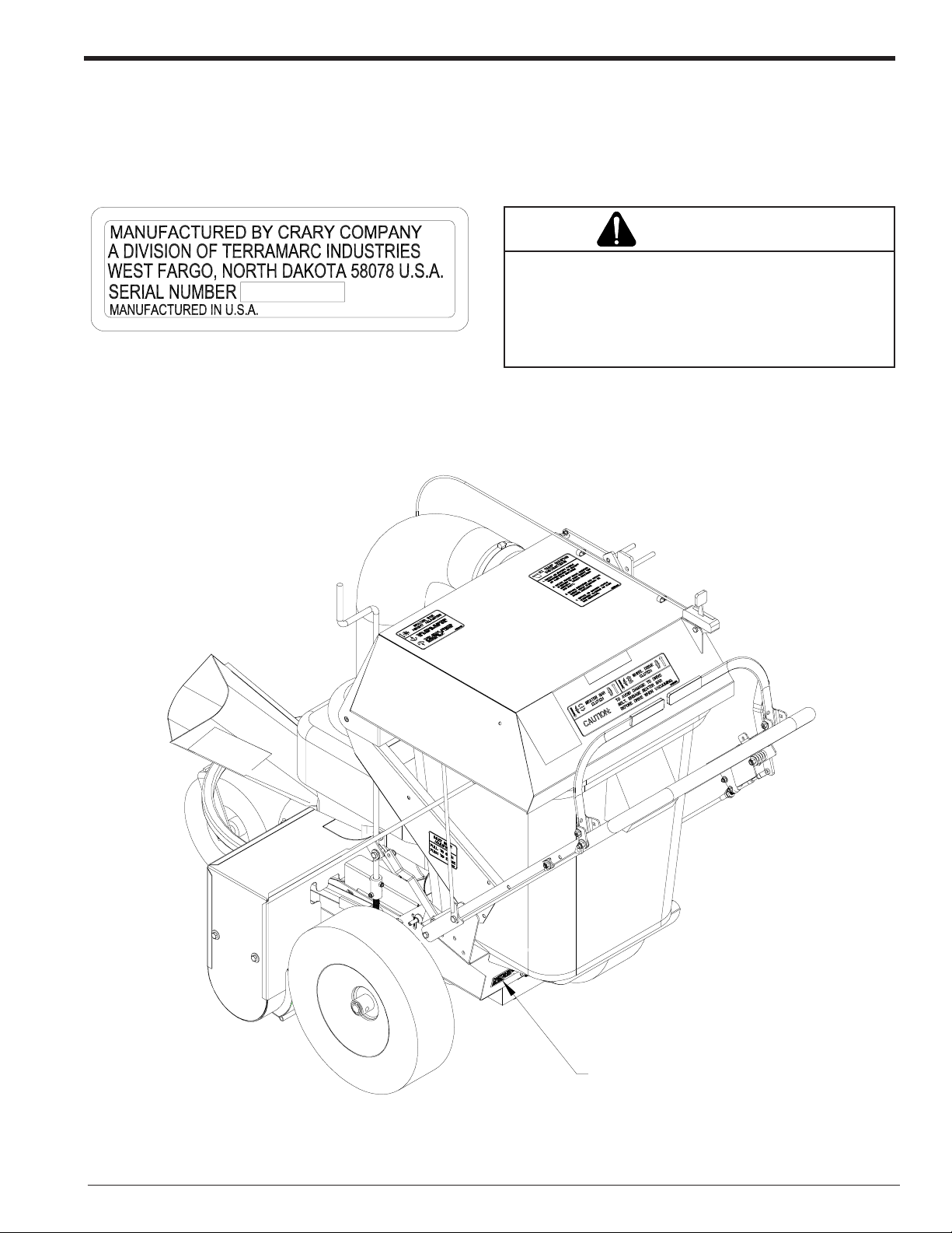
SERIAL NUMBER LOCATION
Always give your authorized Bear Cat dealer the serial number of your Crary Bear Cat Bear Vac when ordering parts,
requesting service or any other information. Please record the serial number in the space provided below and on the
warranty and registration card.
WARNING
To prevent personal injury or property damage: Shut
YXXXXX
Fig. # 1 Serial number decal
Serial Number ________________________
off engine, disconnect spark plug wire, make sure that
all moving parts have come to a complete stop, before
obtaining serial number, servicing, adjusting or repairing.
SERIAL NUMBER
DECAL
Fig. #1, Serial number decal
Bear Vac Pro Operator’s Manual
I
Page 4

Section Description Page
SAFETY .................................................................................................................................... 1
BEFORE OPERATING ................................................................................................................ 2
OPERATION SAFETY ................................................................................................................. 2
MAINTENANCE AND STORAGE SAFETY .................................................................................. 2
SAFETY DECAL LOCATIONS ..................................................................................................... 3
ASSEMBLY .................................................................................................................................... 4
ADDING MOTOR OIL TO ENGINE (ALL MODELS) ..................................................................... 4
ASSEMBLY TORQUE CHART .................................................................................................... 4
ASSEMBLY INSTRUCTIONS (ALL MODELS) ............................................................................. 5
FEATURES AND CONTROLS IDENTIFICATION .......................................................................... 6
DESCRIPTION OF OPERATION .................................................................................................. 6
OPERATION .................................................................................................................................... 9
USE OF CONTROLS ................................................................................................................... 7
FILLING THE TANK ..................................................................................................................... 9
STARTING THE BEAR VAC PRO ................................................................................................ 9
STOPPING THE BEAR VAC PRO ............................................................................................... 9
CHIPPING ................................................................................................................................. 10
VACUUMING ............................................................................................................................. 10
ENGAGING THE DRIVE ............................................................................................................ 11
BEATERBAR ADJUSTMENTS .................................................................................................. 11
EMPTYING THE TUB ................................................................................................................ 12
VACUUMING AND CHIPPING GUIDE ....................................................................................... 12
Contents
SERVICE & MAINTENANCE ............................................................................................................................ 12
MAINTENANCE SCHEDULE ..................................................................................................... 13
REPLACING THE DRIVE BELT ................................................................................................. 14
REPLACING THE BEATERBAR BELT ....................................................................................... 15
REMOVING THE CHIPPER BLADES ........................................................................................ 16
SHARPENING THE CHIPPER BLADES .................................................................................... 16
GREASING ............................................................................................................................... 17
TROUBLESHOOTING ................................................................................................................ 18
Bear Vac Pro Operator’s ManualII
Page 5

Bear Vac Pro Limited Warranty
Crary Bear Cat Bear Vacs are warranted for one year from date of sale for consumer and commercial or
rental operations.
Within the above stated period, Crary Co. will replace any part(s) found to be defective in material and/or
workmanship, after the receipt of the part in our plant. Labor costs to replace these defective parts will be
paid at a Crary established labor rate and time allowed (flat rate) for repair. All transportation charges
incurred in shipping part(s) are the responsibility of the purchaser.
This warranty is void in the case of accidents, failure to perform normal maintenance, or failure to follow
those instructions listed in the service manual. This warranty is also in lieu of all other expressed warranties
and voids any implied warranty as to the merchantability or fitness of the product for a particular purpose
and of any other obligation on the part of Crary Co. Some states do not allow limitations on how long the
implied warranty lasts, so the above limitation may not apply to you.
This warranty applies only to parts or components which are defective, and does not cover necessary
repair due to normal wear, misuse, accidents, or lack of proper maintenance. Components subject to
wear, such as filter bags, wheels, hoses, cables, fan housings, etc., are not included in the warranty.
Regular routine maintenance of the unit to keep it in proper operating condition is the responsibility of the
owner.
All warranty repair reimbursable under the Crary Co. warranty must be performed by an authorized Bear
Cat service dealer using Bear Cat approved replacement parts. Repair or attempted repair by anyone other
than an authorized Bear Cat service dealer is not reimbursable under the Crary Co. warranty. In addition,
these unauthorized repair attempts may result in additional malfunction, the correction of which is not
covered by warranty.
Crary Co. is not liable for indirect, incidental, or consequential damages in connection with the use of this
product including any cost or expense or providing substitute equipment or service during periods of
malfunction or non-use.
Some states do not allow the exclusion of incidental or consequential damages, so the above exclusion
may not apply to you. This warranty gives you specific legal rights. You may also have other rights which
vary from state to state.
Be sure to note the Bear Vac serial number in any correspondence with Crary Co. or any authorized Bear
Cat dealer.
Crary Company
A Division of TerraMarc Industries
237 12th St. NW • P.O. Box 849
West Fargo, ND 58078-0849
(701)282-5520 • FAX: (701)282-9522
www.bearcatproducts.com
www.terramarc.com
Bear Vac Pro Operator’s Manual
III
Page 6

NOTES
Page 7
1
Safety
Section
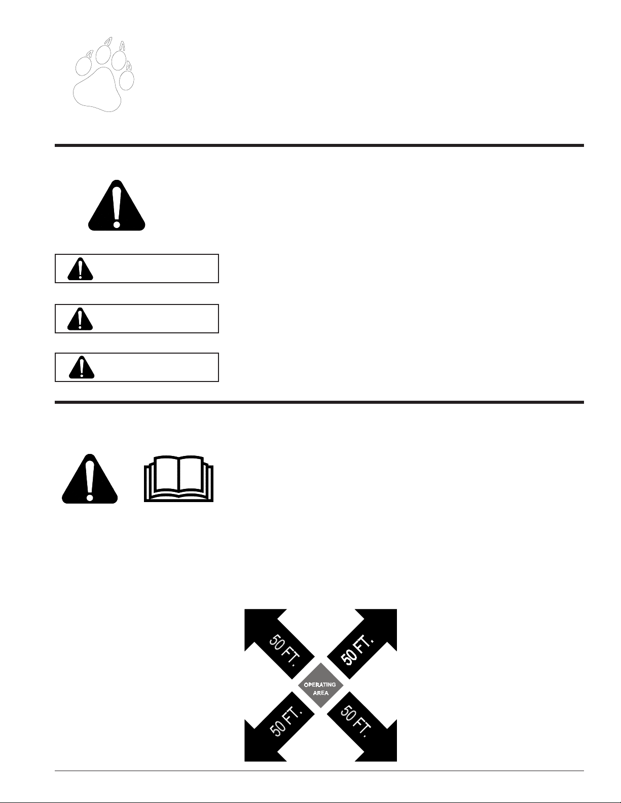
THE SAFETY ALERT SYMBOL
This is the safety alert symbol. It is used in this Owner / Operator’s Manual and on your machine
to alert you to potential hazards.
Whenever you see this symbol, read and obey the safety message that follows it. Failure to obey
the safety message could result in personal injury, death or property damage
DANGER
WARNING
CAUTION
BEFORE OPERATING
1. Read this Owner / Operator’s
manual and the separate Engine
Owner’s manual carefully before
operating this equipment. Be completely familiar with the controls
and the proper use of this equipment.
2. Before inspecting or servicing any
part of the machine, stop engine,
wait for all parts to stop moving,
and disconnect spark plug wire.
Indicates an imminently hazardous situation that, if not avoided, will result in
death or serious injury.
Indicates a potentially hazardous situation that, if not avoided, could result in
death or serious injury.
Indicates a potentially hazardous situation that, if not avoided, may result in
minor or moderate injury.
4. Familiarize yourself with all of the
safety and operating decals on this
equipment and on any of it’s attachments or accessories.
5. Do not allow children or any person unfamiliar with the use of the
unit to use this machine.
6. Keep the area of operation clear of
all persons, particularly small children. Keep bystanders at least
50 feet (15 meters) away from the
area of operation.
7. Do not run this equipment in an
enclosed area. Engine exhaust
contains carbon monoxide gas, a
deadly poison that is odorless,
colorless, and tasteless. Do not
operate this equipment in or near
buildings, windows, or air conditioners.
8. Always use an approved fuel container. Do not remove gas cap or
add fuel when engine is running.
Add fuel to a cool engine only.
9. Do not fill fuel tank indoors. Keep
open flames, sparks, smoking materials, and other sources of combustion away from fuel.
Be aware that rotating parts slow
down gradually after engine is shut
off.
3. Keep safety decals clean and legible. Replace missing or illegible
safety decals.
10. Do not operate this machine if you
are under the influence of alcohol,
medications, or substances that
can affect your vision, balance, or
judgement. Do not operate if tired
or ill. You must be in good health
to operate this machine safely.
Page 1Bear Vac Pro Operator’s Manual
Page 8
Safety
BEFORE OPERATING
11. Use only in daylight or good artificial light.
12. Never use without proper guards
in place.
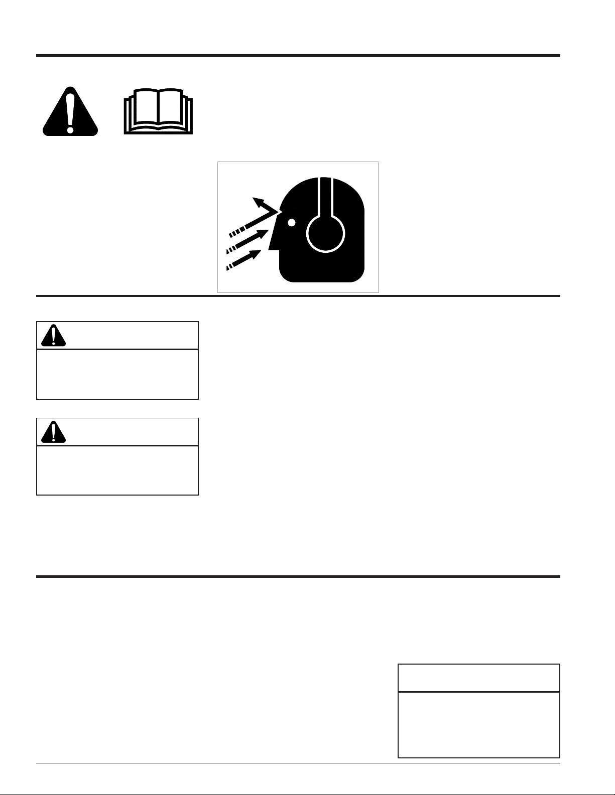
13. Wear safety glasses at all times
while operating this machine.
One pair of safety glasses is provided.
14. Wear ear protection at all times
OPERATION SAFETY
WARNING
Keep hands, feet and clothing out of
inlet opening while machine is operating to avoid personal injury.
WARNING
Wear eye, and hearing protection at
all times while operating the Bear Vac
Pro.
while operating the Bear Vac Pro.
15. Avoid wearing loose fitting clothing. Never operate this machine
wearing clothing with drawstrings that could wrap around
or get caught in the machine.
WRONG
1. Do not allow hands, or any part of
body or clothing near any moving
parts.
2. Shut off engine immediately if the
Bear Vac Pro strikes any foreign object or the machine starts vibrating.
Allow the machine to stop completely. After machine stops:
A. Shut off engine
B. Remove spark plug wire.
C. Inspect for damage.
D. Replace or repair any
damaged parts.
E. Check for and tighten any
loose parts.
3. Do not allow processed material to
build up in the discharge area; this
may prevent proper discharge and
can result in kickback of material
through the feed opening.
16. Check that all screws, nuts,
bolts, and other fasteners are
properly secured before starting
the machine. Check all screws,
nuts, bolts, and other fasteners
for proper tightness to ensure everything is in proper working condition once every 10 hours of operation.
17. Keep all guards, deflectors, and
shields in place and in good
working condition.
18. Do not transport or move machine while the machine is running.
4. Stand clear of the discharge area
when operating this machine.
5. Do not overreach. Keep proper bal-
ance and footing at all times.
6. Keep the engine clear of debris and
other accumulations.
7. Do not tamper with the engine gov-
ernor settings on the machine; the
governor controls the maximum safe
operating speed and protects the engine and all moving parts from damage caused by over speed.
8. Setting up your work site so you are
not endangering the public is critical for safety.
9. Shut off engine and allow machine
to stop completely before clearing
debris if the machine becomes
clogged.
MAINTENANCE AND STORAGE SAFETY
1. Shut off machine and disconnect the
spark plug wire when this equipment
is stopped for service, inspection,
or storage.
2. Replace any missing or unreadable
safety decals. Refer to the parts
manual for part numbers when ordering safety decals from an area
Bear Cat dealer.
3. Store the machine out of reach of
children and where fuel vapors will
Page 2 Bear Vac Pro Operator’s Manual
not reach an open flame or spark.
Drain the fuel and dispose of it in a
safe manner for storage periods of
three months or more.
4. Allow machine to cool before storing in an enclosure.
5. Never store this machine with fuel
in the fuel tank inside a building
where fumes may reach an open
flame or spark, or where ignition
sources are present such as hot
water and space heaters, furnaces,
clothes dryers, stoves, electric motors etc.
NOTE
See engine owners manual or contact the engine manufacturer for
engine safety instructions and decals.
Page 9
Safety
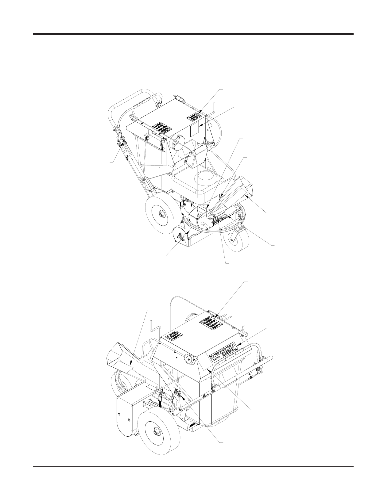
SAFETY DECAL LOCATIONS
Familiarize yourself with all of the safety and operational decals on the machine and the associated hazards. Make certain
that all safety decals and operational decals on this equipment are kept clean and in good condition. The decals are shown
below at reduced sizes. If you need a replacement decal, please refer to the parts catalog. Decals that need replacement
must be applied to their original locations.
DECAL,
BEATER BAR
DECAL,
F;YING DEBRIS
BLADE
DECAL,
ACCESS COVER
DECAL,
DECAL,
SHIFT LEVER
SHIELD DANGER
DECAL,
BLADE DANGER
DECAL,
SMALL DANGER
DECAL,
75111 MODEL
DECAL,
EZ DUMP
DECAL,
OPERATING
INSTRUCTIONS
DECAL,
SMALL BEARCAT
DECAL,
DRIVE
Fig. #2
DECAL,
REAR FLYING DEBRIS
DECAL,
INLET DOOR
Page 3Bear Vac Pro Operator’s Manual
Page 10

2
Assembly
Section
Your Bear Vac Pro may arrive totally or partially assembled. If your machine arrives partially assembled, you may need to
perform the steps in this section.
ADDING MOTOR OIL TO ENGINE (ALL MODELS)
IMPORTANT
Motor oil must be added
to the engine before it is
started.
1. The machine was shipped without
oil in the engine. Fill the engine
crankcase with the amount of oil
specified in the engine owners
manual.
2. To determine which type of oil to use,
refer to the engine owners manual
included in the owners kit of the Bear
Vac Pro.
ASSEMBLY TORQUE CHART
UNIFIED INCH BOLT TORQUE VALUES (COARSE THREAD)
(unless otherwise specified in the manual)
Bolt
Diameter
"A"
1/4" 7.5 5.5 12 9 17 12.5
5/16”1511251835 26
3/8” 27 20 44 33 63 46
7/16” 44 32 70 52 100 75
1/2” 67 50 110 80 150 115
9/16” 95 70 155 115 225 160
5/8” 135 100 215 160 300 225
3/4” 240 175 375 280 550 400
7/8” 240 175 625 450 875 650
1” 360 270 925 675 1300 975
1-1/8” 510 375 1150 850 1850 1350
1-1/4” 725 530 1650 1200 2600 1950
1-3/8” 950 700 2150 1550 3400 2550
1-1/2” 1250 930 2850 2100 4550 3350
SAE 2
(N.m) (ft - lb) (N.m) (ft - lb) (N.m) (ft - lb)
Bolt Torque *
SAE 5 SAE 8
3. Remove the oil fill plug.
4. Checking as necessary, add oil to
the motor until the dipstick shows
the correct reading.
Page 4 Bear Vac Pro Operator’s Manual
Page 11

ASSEMBLY INSTRUCTIONS (ALL MODELS)
Assembly
WARNING
To prevent personal injury or property damage: Shut off engine, disconnect spark plug wire, and make
sure that all moving parts have come
to a complete stop, before servicing, adjusting or repairing.
The Bear Vac Pro is shipped with the
handlebar not attached to the machine.
1. Thread the two tie rods into the pivot
pins located on the bucket crank
weldment. Make sure the rods are
threaded evenly -- they will adjust
how high the bucket top weldment
lifts.
2. Align the tie rod, handlebar clamp,
and handlebar with the bolt holes
called out on Fig. #3. Note: The bottom hole used will determine handlebar height.
3. Insert (4) 5/16” x 2” bolts through tie
rod, handlebar clamp, and Bear Vac
Pro frame.
4. Place washer and locknut onto ends
of bolts.
5. Check lift of bucket top weldment,
and handlebar height. Adjust as
necessary.
6. Tighten bolts to proper torque.
5/16 NUT
NYLOCK
Fig. #3
5/16 FLAT
WASHER
HANDLE BAR
CLAMP
5/16 X 2"
BOLT
TIE ROD
Page 5Bear Vac Pro Operator’s Manual
Page 12

Features & Controls
FEATURES AND CONTROLS IDENTIFICATION
Learn the location of the features and controls on your machine before operating.
HANDLEBARS
WHEEL DRIVE
CLUTCH
ENGINE
THROTTLE
GEAR SHIFT
CONTROL
EZ DUMP
HANDLES
BEATER BAR
CLUTCH
ELECTRIC START
BEATER BAR
HEIGHT ADJUSTOR
BATTERY HOUSING
CHIPPER INTAKE
ENGINE
BEATER BAR
HOUSING
Fig. #4, features and controls. (Note: Electric start and battery housing is found only on the 75111 model.)
DESCRIPTION OF OPERATION
Understanding how your machine works will help you achieve the best results when using your Bear Vac Pro.
The Bear Vac Pro vacuums in debris through the beater bar housing. Material can also enter through the chipper intake. The
debris then travels through the hose to the EZ dump container. When full, the container can be removed from the machine
and dumped.
Page 6 Bear Vac Pro Operator’s Manual
Page 13

USE OF CONTROLS
Model #75011
WARNING
To prevent personal injury or property damage: Shut off engine, disconnect spark plug wire, and make
sure that all moving parts have come
to a complete stop, before servicing, adjusting or repairing.
1. Handlebars: The height of the
handlebars is adjustable.
2. Chipper intake: Hard materials
such as branches and rolled newspaper can be chipped here.
3. Engine: Provides power for the
unit.
4. Engine Throttle: Changes engine
speed, turns the engine on and off,
and places the engine in choke.
5. Wheel Drive Clutch: This control
engages the transmission and
drives the Bear Vac. Release the
bail when shifting.
6. Gearshift control: This control shifts
the self-propelled transmission
between five forward gears and one
reverse gear. To avoid premature
transaxle failure use the clutch
when shifting the machine out of
neutral, or between the reverse and
forward setting. The clutch does
not need to be used when shifting
between forward gears, unless under heavy load.
7. Beater Bar Clutch: Engages and
disengages the beater bar.
8. Beaterbar height adjuster: Adjusts
the height of the beater bar.
9. EZ Dump handles: Used to open
the machine to allow the debris tub
to be removed and emptied. Make
sure the handles are locked before operating. Refer to the decal
(14036-00) for specific instructions
on using the air shut off and removing the tub.
10. Inlet Door Adjuster (not shown):
Adjusts how much debris enters
the beater bars, and thereby the
level of compaction.
Features & Controls
Model # 75111
WARNING
To prevent personal injury or property damage: Shut off engine, disconnect spark plug wire, and make
sure that all moving parts have come
to a complete stop, before servicing, adjusting or repairing.
The electric start model includes all the
features of the manual starting model.
The different features between the two
models are listed here.
1. Electric Start switch: On electric
start models only. This switch engages the starter. When starting
use short bursts. Long periods of
use can damage the starter.
2. Battery Housing: The battery is
nestled above the engine in this
housing.
Page 7Bear Vac Pro Operator’s Manual
Page 14

4
Operation
Section
WARNING
Before operating your machine, be
sure you read and understand all
safety, controls and operating instructions in this Owner/Operators
manual and on your machine.
Failure to follow these instructions
can result in serious injury or property damage.
As with any other piece of outdoor
power equipment, getting the “feel” for
how your machine operates and getting
to know the best techniques for
particular jobs are important to overall
good performance.
Read this section thoroughly before you
start the engine. The instructions given
here will help you become familiar with
your machine and have you operating
efficiently in a short time.
This section covers:
• Filling the tank
• Starting the Bear Vac Pro
• Stopping the Bear Vac Pro
• Chipping
• Vacuuming
• Engaging the drive
• Beaterbar adjustments
• Emptying the tub
Fig. #5, Bear Vac in action
Page 8 Bear Vac Pro Operator’s Manual
Page 15

Operation
FILLING THE TANK
DANGER
Gasoline is highly flammable
and its vapors are explosive. To
prevent personal injury or property damage:
Store gasoline only in approved
containers, in well ventilated, unoccupied buildings, away from sparks
or flames. Do not fill the fuel tank
while the engine is hot or running,
since spilled fuel could ignite if it
comes in contact with hot parts or
sparks from ignition. Do not start
the engine near spilled fuel. Never
use gasoline as a cleaning agent.
FILLING THE FUEL TANK
Fuel Type:
For best results use only clean, fresh,
unleaded gasoline with a pump sticker
octane rating of 87 or higher. In countries using the Research method, it
should be 90 octane minimum.
Purchase gasoline in small quantities
and store in clean, approved containers. A container with a capacity of 2
gallons or less with a pouring spout is
recommended. Such a container is
easier to handle and helps eliminate
spillage during refueling. DO NOT MIX
OIL WITH GASOLINE.
Gasoline Alcohol blends
Gasohol (up to 10% ethyl alcohol, 90%
unleaded gasoline by volume) is approved as a fuel for Honda engines.
Other gasoline/alcohol blends are not
approved.
Gasoline Ether blends
Methyl Tertiary Butyl Ether (MTBE) and
unleaded gasoline blends (up to a maximum of 15% MTBE by volume) are
approved as a fuel for Honda engines.
Other gasoline/ether blends are not
approved.
To Add Gasoline.
1. Stop engine, wait for all parts to stop
moving, then disconnect the spark
plug wire. Allow the engine and muffler to cool for at least three minutes.
2. Clean area around fuel fill cap and
remove cap.
3. Using a clean funnel, fill fuel tank to
1/2” below bottom of filler neck to
provide space for any fuel expansion. Install fuel fill cap securely and
wipe up any spilled gasoline.
STARTING THE BEAR
VAC PRO
Move machine to a clear, level
area outdoors before starting. Do
not operate in the vicinity of bystanders. Make sure the chamber
is empty before starting. Also, do
not engage the bail while starting
self propelled models.
1. Reference the Honda Owners
Manual.
2. Check engine oil level before starting. Do not overfill or underfill oil. The
Honda engine is equipped with an
oil level sensor and will not allow the
engine to start in either scenario.
3. Place the throttle control on Honda
engines into the run or choke position, depending upon engine temperature.
4. Pull the recoil starter until the engine starts. Make sure the starting
cord retracts.
5. On electric models turn the ignition
key to the right to engage starter.
Do not engage starter for long periods.
6. Move throttle to the desired position.
7. For a Cold Engine — Gradually
return the throttle control from the
STOPPING THE BEAR VAC PRO
1. Reference the Honda Owner Manual.
WARNING
Allow the machine to come to
complete stop before inspection
or servicing.
2. Move the throttle to the “slow” or “low” idle position.
3. Allow the engine to run at idle for 30-60 seconds; then stop the engine by
moving the throttle to the off position.
choke position to the run position
as the engine warms up.
Fig. #6, electric start key switch
4. Allow machine to come to a complete stop.
Page 9Bear Vac Pro Operator’s Manual
Page 16

Operation
CHIPPING
Fig. #7, Chipping
1. Shift transaxle into neutral.
2. Select limbs that are 1/2” to 3” in diameter.
3. Trim side branches that cannot be bent over enough to fit
into the chipper chute. Hold small branches together in
bundle and feed simultaneously.
4. Place limb, butt end first, into chipper chute until it contacts the chipping blades. The actual feed rate of the
limb into the chipper will depend upon the type of material fed, the sharpness of the cutting blades and the diameter of the branch.
5. Alternately insert and retract the limb or continuously
insert at a rate that will not kill the engine. Rotating the
branch as you feed it will improve cutting action.
Tips:
-- Avoid overfeeding into the chute.
VACUUMING
NOTE
Please read and follow all safety instructions in this
manual. Failure to operate the Bear Vac Pro in
accordance with the safety instructions MAY RESULT
IN PERSONAL INJURY!
IMPORTANT
Exclude pieces of metal, rocks, bottles, and other
foreign objects when vacuuming.
TIPS:
1. Vacuum heavy, soggy, or stringy material at a slow ground
speed. Feeding too much material into the vacuum will
likely lead to clogging.
2. Check the debris tub frequently and empty if necessary.
3. Avoid vacuuming sticks and other foreign objects -- they
will jam the beater bar.
4. Loosen matted or compacted material with a rake before
vacuuming.
5. Be careful when vacuuming around gravel, gardens, lawn
ornaments, etc. Never attempt to remove objects from
the beater bar when the machine is running.
6. Vacuum frequently to avoid excessive leaf buildup.
7. To obtain greater reduction in vacuumed material, install
the shredder grate. Note: The use of the shredder grate
is optional. The speed of the beaterbar will break and/or
reduce material quite well without it. However, when using the shredding grate, wet material will have a tendency
to wrap and plug easier. The Bear Vac Pro comes with
the shredder grate installed.
-- Whenever possible chip branches when they are fresh.
Green material chips better than dry material.
-- Keep the chipper blades sharp. Severe vibration or slow
feeding are signs the blades may be dull.
-- Do not point your arms into the chute; keep them perpendicular to the branch.
-- Keep your face and body safely away from the chipper
chute and branches.
Page 10 Bear Vac Pro Operator’s Manual
Fig. #8, Shredder Grate
Page 17

Operation
ENGAGING THE DRIVE
The self propelled Bear Vac Pros are engaged with the clutch
engagement bail located on the handlebar. When the bail is
brought to the bar the clutch is engaged and the machine
moves forward. When the bail is released the speed of the
machine can be adjusted between five forward settings using the transmission shift control located on the right of the
handlebar. To shift into reverse, first release wheel drive clutch.
Then pull the shift lever out and back. Engage the transaxle
by pulling the wheel drive clutch.
BEATERBAR ADJUSTMENTS
There are two adjustments that can be made on the
beaterbar. The first will set the height of the beaterbar, and
the second limits how much material enters the beaterbar.
Beaterbar height:
The height of the beaterbar in relation to the ground can be
changed by turning the Beaterbar Height Adjuster. Turning
the lever clockwise raises the beaterbar. Turning the lever
counterclockwise lowers the beaterbar.
Adjusting Inlet Door:
The inlet door can also be adjusted. Pulling on the lever
raises the door. Pushing on the lever lowers the door. The
door must be raised when vacuuming dense or deep material.
The door must be lowered when vacuuming sparse material
to achieve the same degree of compaction. This control is a
friction device and the tension can be adjusted. Tighten or
loosen the friction point as desired.
Fig. #9, Wheel Drive Clutch
Fig. #10, Transmission shift control
Fig. #11, Adjusting Beaterbar height
Fig. #12, Adjusting Inlet Door
Page 11Bear Vac Pro Operator’s Manual
Page 18

Operation
gg
g
g
g
g
g
g
g
g
EMPTYING THE TUB
1. Lower handle B. This is the air shut off handle and will
shut off air flow into the container.
2. Turn handle A counter clockwise. This will lift up the bucket
top of the Bear Vac Pro.
3. With the bucket top open remove the tub from the Bear
Vac Pro.
4. Dump the container into a suitable storage or collection
bin.
5. Place the tub back onto the Bear Vac Pro.
6. Lower the bucket top by turning handle A clockwise.
7. Raise handle B to lock the tub in place and open the shut
off valve.
Notes:
• Use tub at all times.
Fig. #13, Lifting the tub
• Empty tub before it fills completely. A full tub will cause
performance to decrease or stop completely.
• Empty tub completely before storage.
VACUUMING AND CHIPPING GUIDE
MATERIAL BEATER BAR/VACUUM CHIPPER
Dry Leaves YES NO
Damp Leaves YES NO
Wet, Matted Leaves
Pine Needles YES NO
Cornstalks NO
Half-Rotted Compost YES YES
Grass Clippin
Vines NO
Limp, Green Ve
Newspaper YES
ht Brush NO YES
Li
Lar
er Branches NO
s YES NO
etation
YES: Vacuum heavy or so
a slow
YES: Be sure to
wrap around beater bar
round speed
y material at
o slowly so vines don't
Fig. #14, Removing the tub
NO
YES: Be sure to clean dirt from roots as
this will cause blades to dull.
YES: Cut into shorter len
into chipper chute
YES: Drop into chipper chute, use stick to
tamp if necessary
YES: Roll up a couple sections at time
and drop into chute
YES: Re
if necessary
ulate feed rate and branch size
ths and drop
Page 12 Bear Vac Pro Operator’s Manual
Page 19

5
Service & Maintenance
Section
WARNING
To prevent personal injury or property damage: Shut
off engine, disconnect spark plug wire, and make sure
that all moving parts have come to a complete stop
before, servicing, adjusting or repairing.
MAINTENANCE SCHEDULE
The following items listed in the service and maintenance
schedule are to be checked, and if necessary, corrective
action should be taken. This schedule is designed for units
operating under normal conditions. If the unit is operating in
adverse or severe usage conditions it may be necessary for
the items to checked and serviced more frequently.
See engine owners manual for further maintenance and
troubleshooting information.
NOTE:
After using the Bear Vac Pro for three hours the beaterbar
and transaxle engagment may need to be adjusted. The
handlebar levers, when cycled, should engage fully and release completely, otherwise they need to be adjusted. For
adjustment locations see Fig. # 15 and #16.
Fig. #15, Adjusting transaxle engagement
SERVICE AND MAINTENANCE SCHEDULE
COMPONENT
FUEL TANK FILL
AIR CLEANER CHECK AND CLEAN¹
AIR INTAKE CLEAN¹
ENGINE OIL CHANGE¹
ENGINE OIL CHECK
FUEL FILTER REPLACE
SPARK PLUG
NUTS AND BOLTS CHECK
BELT CONDITION CHECK
BELT TENSION CHECK
GREASE ZERKS LUBE
ENTIRE MACHINE CLEAN
¹ PERFORM MORE FREQUENTLY UNDER EXTREMELY DUSTY CONDITIONS.
MAINTENANCE
REQUIRED
CHECK CONDTION AND
GAP
Refer to Engine
Operator manual
•
•
•
•
•
Fig. #16, Adjusting beaterbar engagement
FREQUENCY
BEFORE
EACH
USE
EVERY
8
HOURS
EVERY
25
HOURS
EVERY
HOURS
•
•
•
•
•
•
50
•
Page 13Bear Vac Pro Operator’s Manual
Page 20

Service & Maintenance
REPLACING THE DRIVE BELT
1. Remove the belt guard, following Fig. #15.
2. Remove the chipper blade access cover.
3. Remove chipper blades from the rotor.
4. Loosen the belt guide surrounding the rear of the transmission belt.
5. Remove the old belt. The easiest way is to cut the belt
and slide it out.
6. Insert the new belt into the rotor housing and hook into
one of the chipper slots in the rotor. Rotate the rotor to
move the belt above the fan. Be sure the belt goes under
the fan blades and on top of the fan.
7. Pull the excess new belt to the rear of the machine and
slide it onto the top pulley of the engine. If the beaterbar
belt is attached the new transmission belt will have to be
threaded through the beater bar belt.
8. Position the belt onto the transmission pulley, sliding it
between the belt guide.
REAR BELT
5/16" FLAT
5/16" NYLOCK
GUARD
BELT GUIDE
WASHER
NUT
5/16" NYLOCK
5/16" FLAT
NUT
WASHER
TRANSAXLE
LAWNVAC
Fig. #17, Belt guide removal
DRIVE
PULLEY
1/4" TO 1/2"
DEFLECTION IS
ACCEPTABLE
DRIVEN
PULLEY
DRIVE BELT
TENSION
9. Engage the bail and set the position of the transmission
belt guide. There should be 1/8” of clearance between
the belt guide and the top of the belt.
10. To set the proper tension of the belt, set the idler arm so
there is approximately 1/8” to 1/4” of deflection on the
belt.
10. Reattach the belt covers and operate the unit as instructed.
Page 14 Bear Vac Pro Operator’s Manual
Page 21

REPLACING THE BEATERBAR BELT
Service & Maintenance
1. Remove the belt guard covering the beater bar. Never run
the machine with the belt cover off.
2. Remove the chipper blade access cover.
3. Remove chipper blades from the rotor.
4. Loosen the three belt guides.
5. Remove the idler pivot bolt.
6. Insert the new belt into the rotor housing and hook into
one of the chipper slots in the rotor. Rotate the rotor to
move the belt above the fan. Be sure the belt goes under
the fan blades and on top of the fan.
7. Remove the old belt. The easiest way is to cut the belt
and slide it out.
8. Pull the excess new belt to the rear of the machine and
slide it onto the bottom pulley.
9. Position the belt correctly. Slide it under the belt guides,
around the idler pulleys, and over the beaterbar pulley.
10. Engage the bail and set the position of the beaterbar
belt guide. There should be 1/8” of clearance between
the belt guide and the belt.
11. Reinstall the idler pivot bolt.
12. Reattach the belt covers and operate the unit as instructed.
DRIVE PULLEY
BEATER BAR
BELT
BEATER BAR
IDLER PULLEY
PULLEY
Fig. #18, Proper beaterbar belt orientation
Page 15Bear Vac Pro Operator’s Manual
Page 22

Service & Maintenance
REMOVING THE CHIPPER BLADES
Chipper blades must always be kept sharp! It is
recommended they are sharpened approximately every 8
hours of chipping operation, or when branches no longer
self feed. If the blades aren’t sharp severe vibration and
difficulty in chipping will develop.
To remove the chipper blades:
1. Start by removing the chipper blade access cover by removing the 5/16” bolt and washer.
2. Using a block of wood, or a screwdriver, secure the rotor
so it is not able to spin.
3. From the bottom, remove the 5/16” bolts holding the chipper blades onto the rotor.
4. Replace, reverse, or sharpen the blades.
5. Reinstall the 5/16” bolts and tighten to 20 ft/lbs of torque.
SHARPENING THE CHIPPER BLADES
Flip the blade or regrind the angled edge of the chipping
blades to 45 degrees. (refer to figure below) The blades can
be ground on a bench grinder or by a professional. Make
sure some type of fixture is used to correctly hold the blade
at the proper angle. Be careful when grinding so that the
blade does not become overheated and change color. (This
will remove the heat-treated properties) Use short grinding
times and cool with water or some type of liquid coolant.
Try to remove an equal amount off of each blade to maintain
rotor balance.
Never sharpen or back grind the flat side of the chipping
blade. This will cause the edge to roll and the chipper blade
will be damaged, resulting in poor chipping performance.
Small imperfections such as nicks, burrs, etc. on the flat
side of the blade will not affect the chipping performance of
the machine.
45°
5/16" FLAT
WASHER
5/16" X 3/4"
BOLT
ACCESS COVER
Fig. #19, Access panel removal
CHIPPER BLADE
5/16" FLAT
WASHER
5/16" NYLOCK
NUT
NEVER SHARPEN OR BACK GRIND THIS SIDE -
POOR FEEDING AND CHIPPING WILL RESULT.
FLAT SIDE
Fig. #20, Chipper blade sharpening
SHARPEN TO A 45° ANGLE.
Page 16 Bear Vac Pro Operator’s Manual
Page 23

GREASING
There are four grease zerks on the Bear Vac Pro. Three are
located on the castor wheel weldment, and one on the
beaterbar belt. The pictures below show the exact locations
of the zerks. They should be greased every 25 hours,
depending upon conditions.
Service & Maintenance
Fig. #21, Grease every 25 hours
Fig. #22, Grease every 25 hours
Fig. #23, Grease every 25 hours
Fig. #24, Grease every 25 hours
Page 17Bear Vac Pro Operator’s Manual
Page 24

Service & Maintenance
p
g
j
j
g
g
pty
p
TROUBLESHOOTING
Before performing any of the correction in this troubleshooting chart, refer to the appropriate information contained in this
manual for the correct safety precautions and operating or maintenance procedures. Contact your nearest dealer or the
factory for service problems with the machine.
PROBLEM POSSIBLE CAUSE CORRECTION
Chipper does not chip. Poor
performance.
Loss of vacuum.
Vacuum not functioning or beater bar
not turning.
Dull chipping blades. Sharpen or replace.
Drive belts loose or worn. Re
Too lar
e of branch. Limit branch size.
Solid object jammed in the unit. Check and remove.
Broken or missing chipper blade. Replace blade.
Intake clogged. Raise inlet door and remove obstruction.
Collection bag full. Remove and empty bag.
Processing chamber clogged. Remove front side access cover and clean area.
Engine not reaching full RPM. Refer to Engine Owners Manual.
Vacuum shut off door closed. Open vacuum shut off door.
Belts slipping or burning. Ensure beater bar is engaged before beginning to
Beater bar jammed. Remove material and revacuum at slower speed.
Beater bar chamber clogged. Remove material and revacuum at slower speed.
Solid object jammed in the unit. Check and remove obstruction.
lace drive belts.
vacuum.
Unusual vibration or noise.
Loss of traction.
Gearshift lever does not shift
properly.
Engine runs poorly.
Chipper blade loose or damaged. Tighten or replace.
Engine cylinder shaft or crankshaft is bent or
damaged.
Loose or missing bolts on unit. Tighten or replace bolts.
Cracked or broken beater bar knives. Replace cracked or broken knives.
Wheels not turning. Check key in axle and wheel assembly.
Stretched or broken drive belt. Replace drive belts.
Wheel drive bail cable not tensioned correctly. Adjust or replace spring.
Malfunction in transaxle. Contact Bear Cat dealer or call factory.
Loose gearshift lever cable. Reconnect cable to bail.
Broken gear shift lever cable. Replace gear shift lever cable.
Clevis not attached to shift arm. Reattach cable to shift arm.
Malfunction in transaxle. Contact Bear Cat dealer or call factory.
Cable not ad
Bad spark plug. Inspect spark plug and replace if necessary.
Incorrect choke settin
Dirty air filter. Clean or replace.
Stale gasoline. Drain gasoline and add fresh fuel.
Dirt or water in fuel tank. Contact engine service dealer.
usted properly.Check ad
.Chan
See Engine Service Dealer.
ustment points.
e choke setting.
Engine won't start or is hard to start.
Gas tank is em
Spark plug wire is disconnected. Connect loose wire to spark plug.
S
ark plug is defective. Replace spark plug.
Gas line is obstructed. Remove gas line at carburetor and check for
Dirty, stale, water-contaminated gas. Drain tank and fill with fresh gasoline.
Flooded engine. Put throttle control in run position and crank
Dirty or plugged air cleaner. Clean air cleaner and replace.
. Fill gas tank.
Page 18 Bear Vac Pro Operator’s Manual
obstruction. Drain gas tank and refill with fresh,
clean gasoline.
engine several times to clear out excess gas.
Page 25

Manual Improvement Program
If you have a suggestion on how to improve this manual, send it to us. Participants whose ideas are
implemented will receive a free pair of Crary genuine leather gloves.
Send your suggestions to:
Crary Company
C/O Technical Writer
237 NW 12th St. Box 849
West Fargo, ND 78078
Suggestions:
Name:
Address:
Phone Number:
Email (if applicable):
Product purchased:
Manual part number:
Page 19Bear Vac Pro Operator’s Manual
Page 26

Page 27

Manual Improvement Program
If you have a suggestion on how to improve this manual, send it to us. Participants whose ideas are implemented will
receive a free pair of Crary genuine leather gloves. The form is located after the torque chart in the manual.
HEALTH WARNING
GASOLINE, DIESEL, AND
OTHER PETROLEUM PRODUCTS
Harmful or fatal if swallowed.
Long-term exposure to vapors has caused cancer in laboratory animals.
• Avoid prolonged breathing of vapors.
• Keep face away from nozzle and gas tank/container
opening.
• Never siphon by mouth.
Failure to use caution may cause serious injury or illness.
CHEMICALS KNOWN TO THE STATE OF CALIFORNIA TO CAUSE CANCER, BIRTH DEFECTS, OR
OTHER REPRODUCTIVE HARM ARE FOUND IN
GASOLINE, DIESEL, CRUDE OIL, AND MANY OTHER
PETROLEUM PRODUCTS AND THEIR VAPORS, OR
RESULT FROM THEIR USE.
READ AND FOLLOW LABEL DIRECTIONS AND USE
CARE WHEN HANDLING OR USING ALL PETROLEUM
PRODUCTS.
ENGINE EXHAUST FROM THIS PRODUCT CONTAINS
CHEMICALS KNOWN TO THE STATE OF CALIFORNIA TO CAUSE CANCER, BIRTH DEFECTS, OR
OTHER REPRODUCTIVE HARM.
Crary Company
A Division of TerraMarc Industries
237 12th St. NW • P.O. Box 849
West Fargo, ND 58078-0849
(701)282-5520 • FAX: (701)282-9522
www.bearcatproducts.com
WARNING
www.terramarc.com
Manufactured in the
United States of America
by Crary Company
 Loading...