

Page 1

Page 2

Before you Begin
DEAR BEAR CAT CUSTOMER,
Thank you for purchasing a Crary Bear Cat product. The Bear Cat line is designed, tested,
and manufactured to give years of dependable performance. To keep your machine
operating at peak efficiency, it is necessary to adjust it correctly and make regular
inspections. The following pages will assist you in the operation and maintenance of your
machine. Please read and understand this manual before operating.
If you have any questions or comments about this manual, please call us toll-free at 1-800247-7335.
If you have any questions or problems with your machine, please call or write your local
factory-authorized Bear Cat dealer.
PLEASE SEND US YOUR WARRANTY CARD
A warranty card is included in your owner's kit packaged with your machine. Please take
the time to fill in the information requested on the card. When you send your completed card
to us, we will register your machine and start your coverage under our limited warranty.
How to Contact
Bear Cat
A
DDRESS
Crary Bear Cat
237 NW 12th Street
PO Box 849
West Fargo, ND
58078
P
HONE
800-247-7335
701-282-5520
Fax: 701-282-9522
E
MAIL
opesales@crary.com
service@crary.com
H
OURS
EMISSION INFORMATION
WARNING
WARNING TO ALL CALIFORNIA
AND OTHER STATES OPERATING
OUTDOOR POWER EQUIPMENT
Under California Law and under the
laws of several other states you are
not permitted to operate an internal
combustion engine using
hydrocarbon fuels on any forest
covered, brush covered or grass
covered land or on land covered with
grain hay or other flammable
agricultural crop, without an engine
spark arrester in continuous effective
working order.
The engine on your power equipment,
like most outdoor power equipment,
is an internal combustion engine that
burns gasoline, a hydrocarbon fuel.
Therefore, your power equipment
must be equipped with a spark
arrester muffler in continuous
effective working order. The spark
arrester must be attached to the
engine exhaust system in such a
manner that flames or heat from the
system will not ignite flammable
material.
M-F, 8 a.m. to 5 p.m.
Central Time
Failure of the owner/operator of the
equipment to comply with this
regulation is a misdemeanor under
California law, and may also be a
violation of other state and or federal
regulations, laws, ordinances, or
codes. Contact your local fire
marshal or forest service for specific
information about what regulations
apply in your area.
The standard muffler installed on the
engine is not equipped with a spark
arrester. One must be added before
use if this machine is intended to be
used in an area where a spark
arrester is required by law. Contact
the local authorities if these laws
apply to you. See your authorized
engine dealer for spark arrester
options.
I
74520 & 74554 Chipper Operator’s Manual
Page 3

Crary Company
A Division of TerraMarc Industries
237 12th St. NW • P.O. Box 849
West Fargo, ND 58078-0849
(701)282-5520 • FAX: (701)282-9522
www.bearcatproducts.com
74520 & 74554 Chipper Operator’s Manual II
Page 4

Contents
Section Description Page
1.0 SAFETY .................................................................................................................................... 2
1.1 BEFORE OPERATING .......................................................................................................... 2
1.2 OPERATION SAFETY ........................................................................................................... 3
1.3 MAINTENANCE AND STORAGE SAFETY ............................................................................ 4
1.4 BATTERY SAFETY ............................................................................................................... 4
1.5 SAFETY DECALS ................................................................................................................. 5
2.0 ASSEMBLY .................................................................................................................................... 6
2.1 GENERAL ASSEMBLY ......................................................................................................... 6
3.0 OPERATION .................................................................................................................................... 7
3.1 GENERAL STARTING INSTRUCTIONS ................................................................................. 7
3.2 STARTING ELECTRIC MODELS ............................................................................................ 7
3.3 TRIMMING ............................................................................................................................. 8
3.4 SELF PROPELLED OPERATION .......................................................................................... 8
3.5 OFF CENTER TILT FEATURE (OCT) ..................................................................................... 8
4.0 SERVICE AND MAINTENANCE ................................................................................................................... 8
4.1 PARALLEL TRIMMING (MODELS 73265, 73350, & 73455) ................................................... 9
4.2 PARALLEL TRIMMING (MODELS 73050, 73450) .................................................................. 8
4.3 OFF CENTER TILT FEATURE (MODELS 74050, 74450, 74455, 74065, 74060) ..................... 9
4.4 ALL MODELS CUTTING HEIGHT ADJUSTMENT ................................................................. 10
4.5 DRIVE BELT CHECKING AND REPLACEMENT .................................................................. 10
4.6 CUTTING STRING REPLACEMENT ..................................................................................... 11
4.7 SELF PROPELLED MODEL CHAIN ADJUSTMENT ............................................................ 12
4.8 ENGINE MAINTENANCE ..................................................................................................... 12
4.9 DEBRIS FILTER CLEANING/REPLACEMENT (MODEL 73050, 74050, 73350) .................... 12
4.10 TROUBLESHOOTING ........................................................................................................ 13
5.0 SPECIFICATIONS .................................................................................................................................. 14
5.1 SPECIFICATIONS................................................................................................................ 14
5.2 BOLT TORQUE .................................................................................................................... 16
Page 5

SERIAL NUMBER LOCATION
Always give your dealer the serial number of your Crary Bear Cat product when ordering parts, requesting service or any
other information.
Please record the serial number in the space provided below and on the warranty and registration card. The serial number
is located on the trimmer frame.
WARNING
To prevent personal injury or property damage: Disengage the source providing power to the machine and
make sure that all moving parts have come to a complete stop, before obtaining serial number, servicing,
adjusting or repairing.
YXXXXX
Fig. #1, Serial number decal
Serial Number ___________________
REPLACEMENT PARTS
Only genuine Bear Cat replacement parts should be used to repair the machine. Bear Cat replacement parts are available
from your Bear Cat dealer. To obtain prompt, efficient service, remember to give the dealer the correct part description and
serial number of the machine.
Please be sure to provide the following information:
1. The SERIAL NUMBER of your machine.
2. The PART NUMBER of the part.
3. The PART DESCRIPTION.
4. The QUANTITY needed.
EZ Trim Mower Owners Manual
Page 1
Page 6
Safety
1
Section
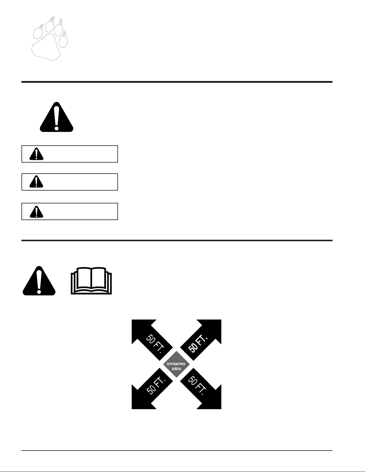
THE SAFETY ALERT SYMBOL
This is the safety alert symbol. It is used in this Owner / Operator’s Manual and on your machine
to alert you to potential hazards.
Whenever you see this symbol, read and obey the safety message that follows it. Failure to obey
the safety message could result in personal injury, death or property damage.
Indicates an imminently hazardous situation that, if not avoided, will result in
DANGER
WARNING
death or serious injury.
Indicates a potentially hazardous situation that, if not avoided, could result in
death or serious injury.
CAUTION
1.1 BEFORE OPERATING
1. Read this Owner / Operator’s
manual. Be completely familiar
with the controls and the proper
use of this equipment.
2. Before inspecting or servicing any
part of the machine, wait for all
parts to stop moving. Be aware that
rotating parts slow down gradually
after power is stopped.
3. Keep safety decals clean and legible. Replace missing or illegible
safety decals.
Indicates a potentially hazardous situation that, if not avoided, may result in
minor or moderate injury.
4. Familiarize yourself with all of the
safety and operating decals on this
equipment and on any of it’s attachments or accessories.
5. Do not allow children or any person unfamiliar with the use of the
unit to use this machine.
6. Keep the area of operation clear of
all persons, particularly small children. Keep bystanders at least
50 feet (15 meters) away from the
area of operation.
7. Do not run this equipment in an
enclosed area. Do not operate this
equipment in or near buildings,
windows, or air conditioners.
8. If needed, always use an approved
fuel container. Keep open flames,
sparks, smoking materials, and
other sources of combustion away
from fuel.
9. Do not operate this machine if you
are under the influence of alcohol,
medications, or substances that
can affect your vision, balance, and
judgement. Do not operate if tired
or ill. You must be in good health
to operate this machine safely.
Page 2
EZ Trim Mower Owners Manual
Page 7
BEFORE OPERATING
10. Use only in daylight or good artificial light.
11. Wear safety glasses at all times
while operating this machine.
1.2 OPERATION SAFETY
12. Never use without proper guards
in place.
13. Avoid wearing loose fitting clothing. Never operate this machine
wearing clothing with drawstrings
that could wrap around or get
caught in the machine.
14. Check that all screws, nuts, bolts,
and other fasteners are properly secured before starting the machine.
Check all screws, nuts, bolts, and
other fasteners for proper tightness
Safety
to ensure everything is in proper
working condition once every 10
hours of operation.
15. Keep all guards, deflectors, and
shields in place and in good working condition.
16. Do not transport or move machine
while the machine is running.
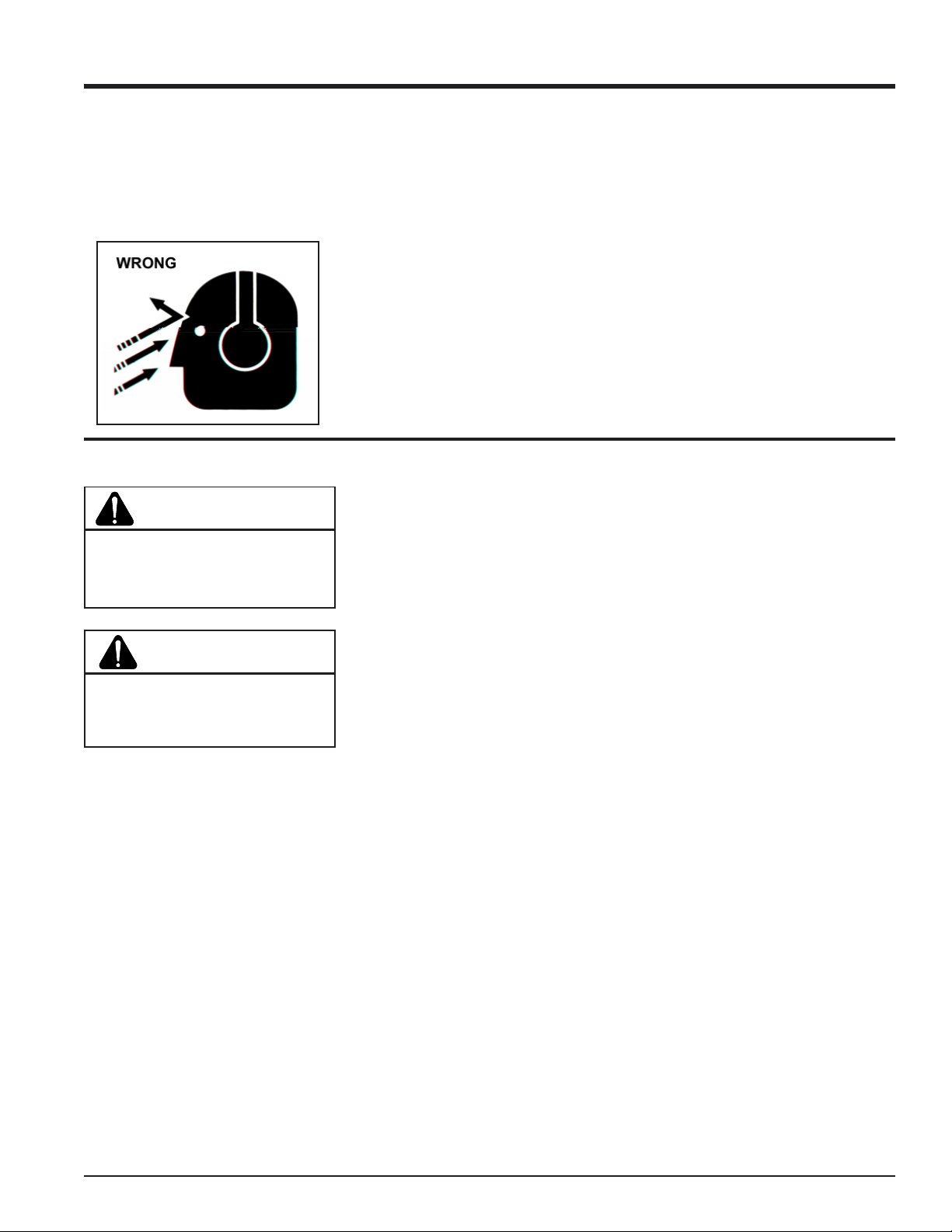
WARNING
Material can kickup or shift suddenly
and cause serious injury or death.
Wear eye and hearing protection.
DANGER
Keep hands, feet and clothing out of
the way of moving parts to avoid serious personal injury.
1. Do not allow hands or any part of
body or clothing near any moving
part.
2. Shut off machine immediately if the
cutting mechanism strikes any foreign object or the machine starts
making an unusual noise or vibrating. Allow the machine to stop
completely. After machine stops:
A. Inspect for damage.
B. Replace or repair any
damaged parts.
C. Check for and tighten any
loose parts.
3. Keep proper balance and footing
at all times.
4. Keep the machine clear of debris
and other accumulations.
5. Ensure debris does not blow into
traffic, parked cars, or pedestrians.
6. Check the bolts for correct torque
every 10 hours of operation.
7. Shut off engine and allow machine
to stop completely before clearing
debris if the machine becomes
clogged.
EZ Trim Mower Owners Manual
Page 3
Page 8

1.4 BATTERY SAFETY
1. Improper use and care of the battery on electric start models can
result in serious personal injury or
property damage. Always observe
the following safety precautions:
A- Poison/Danger - Causes Severe
Burns. The battery contains sulfuric acid. Avoid contact with skin,
eyes or clothing. Keep out of
reach of children.
ANTIDOTE-External Contact:
Flush immediately with lots of water.
ANTIDOTE-Internal: Drink large
quantities of water or milk. Follow
with milk of magnesia, beaten egg
or vegetable oil. Call a physician
immediately.
ANTIDOTE-Eye Contact: Flush
with water for 15 minutes. Get
prompt medical attention.
B- The battery produces explosive
gases. Keep sparks, flame or
cigarettes away. Ventilate area
when charging battery. Always
wear safety goggles when working near battery.
C- The battery contains toxic materi-
als. Do not damage battery case.
If case is broken or damaged,
avoid contact with battery contents.
Neutralize acid spills with a baking soda and water solution. Properly dispose of a damaged or wornout battery. Check with local authorities for proper disposal methods.
D- Do not short circuit battery. Se-
vere fumes and fire can result.
E- Before working with electrical wires
or components: disconnect battery ground (negative) cable first.
Disconnect positive cable second.
Reverse this order when reconnecting battery cables.
Page 4
EZ Trim Mower Owners Manual
Page 9

Safety Decals
1.5 SAFETY DECALS
Safety and instruction decals are located on the chipper frame and engine. Replace any decal that is damaged or
unreadable.
Part # 12254
Part # 12172
Part # 12545
Part # 12252
Part # 16702
EZ Trim Mower Owners Manual
Page 5
Page 10

CAUTION
Remove spark plug wire from spark plug before assembling.
1. Remove units and parts from shipping crate.
2. Stand handlebar upright. Secure the bottom of the
handlebar by inserting bolts to the bottom hole on the
handle support channel. Do not tighten bolts at this
time. Refer to Fig. #2.
3. Adjust the handlebar height. The handlebar height is
set by choosing one of the available three holes on
the handle support channel towards the bottom of the
handlebar’s lower portion.
4. Align the holes on the bottom portion of the handlebar
with the selected holes on the handle support channel. Thread bolts through the holes with the bolt head
facing out.
5. Tighten all bolts by turning counterclockwise while
holding the locknut stationary with the other wrench.
6. Add oil to the engine. Refer to Fig. #3 and to the
engine owners manual for recommended SAE 30
engine oil types and amounts. No special additives
are used with recommended oil types; do not mix oil
with gasoline. Ensure the machine is level when
adding oil. Oil capacity is approximately 20 oz.
Dipstick
Oil Fill
5/16" FLAT WASHER
5/16" X 1" HEX HD BOLT
Fuel Fill
Fig. # 3, Adding oil and gasoline
5/16" NYLOCK NUT
5/16" FLAT WASHER
7. Check oil level. Remove dipstick and wipe with clean
cloth. Reinsert dipstick and tighten. Remove again
to check oil level; oil should be at the full mark.
8. Fill gas tank with fresh, clean, unleaded gasoline. Do
not use fuel that contains methanol or is mixed with
oil. Ensure the machine is level when adding fuel.
Refer to engine owners manual for additional information.
WARNING
Handle fuel with care. Use an approved container and
fill outdoors. Do not add fuel to a running or hot engine.
It is extremely flammable.
Page 6
EZ Trim Mower Owners Manual
Page 11

4
Operation
Section
3.1 GENERAL STARTING INSTRUCTIONS
CAUTION
Move machine to a clear, level area outdoors before starting. Do not operate in the vicinity of bystanders.
Read the safety instructions. Familiarize yourself with
the safety instructions in this manual and the engine owners
manual before starting the EZ Trim Mower.
Fill engine with oil. Do not start before adding oil to the
engine. See engine manual for the type and amount of oil
to use. Machine should be level when filling.
1. Check engine oil level and fill if necessary before
each use. See engine manual for filling and maintenance instructions.
2. Fill fuel tank with fresh, clean unleaded gasoline. DO
NOT MIX OIL WITH GASOLINE.
3.2 STARTING ELECTRIC MODELS
1. Turn the ignition key to ON position.
2. Move the throttle control to the run position.
3. Firmly push the primer bulb 5 times for first time
starting. Firmly push the primer bulb 3 times
thereafter.
4. Pull trimmer bail back.
5. Turn ignition key clockwise to start electric start
engine.
• Use recoil start procedure if the battery is not
charged. Grasp the recoil starter cord handle and
slowly pull until resistance is felt. After resistance
is felt, pull the cord quickly to start the engine and
prevent kickback. Repeat if necessary.
• Use 1 AMP trickle charger to charge battery. Do
not exceed 1.4 AMP initial charge.
6. If engine does not start after 3 tries, push the primer
bulb 3 times, or adjust the choke and engage
ignition again.
WARNING
Handle fuel (gasoline) with care. It is highly flammable.
Always use an approved container and fill tank outdoors.
Never add fuel to a running or hot engine.
3. Move the throttle control to the run position. If the
engine is equipped with a engine fuel valve, turn it to
the on position.
4. If starting for the first time, firmly push the primer bulb
5 times. Thereafter push the primer bulb 3 times
before starting. Or if equipped with a choke, place the
engine in choke.
5. Pull trimmer bail back. Grasp the recoil starter cord
handle and slowly pull until resistance is felt. After
resistance is felt, pull the cord quickly to start the
engine and prevent kickback. Repeat if necessary.
6. If engine does not start after 3 pulls, push the primer
bulb 3 times, or adjust the choke and repeat step 5.
NOTE
Some oil usage is normal. Check level before each use.
See engine operators manual for the type and amount of
oil to use.
NOTE
Continue to hold the bail after the engine is started.
Releasing will stop the engine.
NOTE
A throttle cable is not included on some Briggs &
Stratton powered EZ Trim Mowers (Models 73050,
73350, 73265). On models without a throttle cable,
the throttle is adjusted on the engine.
EZ Trim Mower Owners Manual
Page 7
Page 12

Operation
3.3 TRIMMING
WARNING
Wear safety glasses during operation. Wear proper
clothing to protect feet, legs, and other exposed body
parts.
WARNING
Inspect and clean engine before each use. Debris
accumulation around the muffler can cause a fire.
The intended use of the EZ Trim Mower is trimming, mowing,
and edging. It can be used as a mower or trimmer and
edger after mowing with a lawn mower.
To begin trimming, with the engine running, place the trimmer
head on the ground and begin walking slowly. The wheels
should remain grounded at all times to prevent undue
pressure on the trimmer head. The cutting radius is
dependent on the amount of cutting string used and type of
application. For difficult conditions and edging, using less
than the full cutting radius is recommended.
3.5 OFF CENTER TILT FEATURE
(OCT)
On models 74050, 74060, 74065, 74450, 74455 the OCT
feature is used to edge and trim in hard to reach places.
This features enables both the trimmer head and body to tilt
for trimming close to the ground. The degree of tilt is
dependent on the setting selected on the tilt control grip
located on the right side of the EZ Trim Mower.
Four settings are available:
1. Level. The tilt control grip is set in the position
closest to the rear of the trimmer.
2. 5.4 degrees. The tilt control handle is set in the
second position from the rear of the trimmer.
3. 10.3 degrees. The tile control handle is set in the third
position from the rear of the trimmer.
4. 13 degrees. The tilt control grip is set in the position
closest to the front of the machine for maximum tilt.
3.4 SELF PROPELLED OPERATION
The Self Propelled EZ Trim Mower is used in either push or
self propelled mode.
1. Pull up the self propelled bail located under the
handlebar to start the self propelled mode.
2. Adjust trimmer speed with the shift lever. Position 1
is the slowest and position 3 is the quickest. (The
ground speed ranges from 1 mph in 1st gear to 2
mph in 3rd gear).
3. Operate EZ Trim Mower safely and as intended.
4. To stop the mower release the bail.
Page 8
EZ Trim Mower Owners Manual
Page 13

4.1 PARALLEL TRIMMING (MODELS
73265, 73350, & 73455)
The EZ Trim Mower trimmer body can be adjusted to mow
at an angle. The trimmer body will move up to 2" to the left
or the right. This allows the machine to edge and trim in
hard to reach places. To adjust the parallel trimming setting:
1. Loosen two nuts on the bottom of the trimmer called
out in Fig. #4; the first (A) is located behind the
trimmer spindle, while the other (B) is in the center of
the back of the transmission support plate. Do not
adjust parallel trimming with the trimmer axle. This
will cause the drive chains to fall out of adjustment.
2. Pivot the trimmer body, on the slotted holes, to the
left or right. The trimmer body can pivot either left or
right up to 2".
3. Tighten the nuts loosened in step #1.
4. When finished using the parallel trimming feature
loosen bolts A & B and place the trimmer body in the
original position.
5. Tighten the bolts and resume regular trimming or
mowing.
A
B
EZ Trim Mower Owners Manual
Page 9
Page 14

Service and Maintenance
4.4 ALL MODELS CUTTING HEIGHT
ADJUSTMENT
The EZ Trim Mower standard cutting height is 2-3/4 inches.
Figure number five, below, depicts the trimmer head
assembly when purchased and set at the standard cutting
height.
The cutting height will adjust down approximately 3/4 inch
by turning the trimmer head disk over, see Fig. # 6 & 7). To
adjust the cutting height down, remove the trimmer head
weldment before turning the trimmer head disk.
Fig. #7
1. Insert a 9/16” open end wrench into trimmer frame.
2. Rotate trimmer head until wrench engages with
trimmer shaft.
3. Twist the trimmer head weldment counterclockwise
to remove. Use channel lock or pipe wrench if
necessary.
4. Turn trimmer head disk over and replace on trimmer
spindle.
5. Return trimmer head weldment and turn clockwise to
tighten.
9/16" WRENCH
TRIMMER DISC
TRIMMER HEAD
Fig. #5
OPTIONAL
BEAVER BLADE
4.5 DRIVE BELT CHECKING AND REPLACEMENT
Check the condition of the drive belt annually or after 30
hours of operation, whichever comes first. If the belts are
cracked, frayed, or worn, replace them by following the steps
below.
1. Shut off the engine. Disconnect the spark plug wire.
2. Remove the front cover weldment (requires loosening
and removing three bolts).
3. Loosen the four bolts fastening the spindle hub to the
trimmer bottom frame. This will allow the spindle hub
with the attached trimmer pulley to move freely.
4. Remove the handle support channel (back cover with
tabs to adjust the handlebar). Requires loosening
and removing four bolts.
5. Remove worn or broken belt. If the belt is badly worn
and will not be used again, cut for ease of removal.
6. Install new belt from the front to the back. Feed belt
above the front trimmer pulley and below the rear
pulley.
7. Move the spindle hub by inserting a screwdriver in the
slot on the rear side of the spindle hub and applying
70 lbs. pressure forward until belt is tight. Tighten
bolts.
Page 10
8. Replace front cover and secure with bolts.
9. Replace the handle support channel (back cover with
handlebar adjustment tabs). The bolts should be
secured with the bolt head beneath and the nuts and
washer above the trimmer body.
Fig. #6
EZ Trim Mower Owners Manual
Page 15

Service and Maintenance
4.6 CUTTING STRING REPLACEMENT
WARNING
Before inspecting or servicing any part of the machine,
disconnect the spark plug wire from the spark plug and
make sure all moving parts have come to a complete
stop.
1. Feed the cutting string through the second hole on
either end of the trimmer head leaving approximately
8 inches for the cutting surface. Total recommended
string length is 20-1/2 inches.
2. Continue by weaving the cutting string through the
first hole directly beside the second hole used in Step
1. Pull the cutting string tight.
3. Loop the cutting string back and feed through the first
hole on the opposite end of the trimmer head.
4. Feed through the remaining second hole and pull the
cutting string tight. The cutting strings in the middle
two holes should be the same length. If the length
differs, cut to an even length.
The cutting string can also be wrapped in a variety of ways.
Refer to Fig. #9 and Fig. #10 for examples.
Cutting string is available in two thicknesses, .130 mil
(standard) and .155 mil (heavy duty). The type of string
selected is dependent on the conditions and material being
cut.
Heavier string than .155 mil can be use by making the holes
in the trimmer head larger. The decision to drill the holes
bigger shortens the life of .130 mil and .155 mil string if used
again.
The wrapping method and cutting string thickness chosen
is ultimately based on what is determined the best for the
operator.
When completed, the trimmer head should resemble Fig.
#8.
Fig. #8
Fig. #9
Fig. #10
EZ Trim Mower Owners Manual
Page 11
Page 16

Service and Maintenance
4.7 SELF PROPELLED MODEL CHAIN
ADJUSTMENT
Self propelled models 73265, 73350, & 73455 are driven
with a drive chain. Periodically, this chain will need to be
adjusted. To adjust:
1. Loosen two (2) 5/16” nuts located under the trimmer
axle.
2. Slide the trimmer axle back to tighten the chains.
Slide the trimmer forward to loosen the chains.
3. Retighten 5/16” nuts.
4.8 ENGINE MAINTENANCE
IMPORTANT
Clean grass and buildup from the engine periodically.
Dusty conditions will require frequent cleaning.
Maintenance is essential in preserving engine life. The engine
should be cleaned periodically to remove grass and buildup.
The engine owners manual addresses cleaning the air filter
and changing the oil. Service engine according to the
maintenance schedule in your engine owners manual.
4.9 DEBRIS FILTER CLEANING/REPLACEMENT (MODEL 73050, 74050,
73350)
1. Shut off the engine. Disconnect the spark plug wire.
2. Remove o-ring. Refer to Fig. #12.
3. Remove debris filter from filter base.
4. Clean debris filter or replace if needed.
5. Reinstall debris filter by performing above steps in
reverse order.
O-RING
DEBRIS FILTER
Remember to inspect and clean engine cooling fins as
needed.
DEBRIS FILTER
BASE
Page 12
EZ Trim Mower Owners Manual
Page 17

g
y
y
y
4.10 TROUBLESHOOTING
Problem Probable Cause Suggested Remedies
Cutting strings do not
turn
Broken off or damaged belts Replace belts
Broken spindle Repair spindle
Failed bearings Repair bearings
Cutting string is too weak
Service and Maintenance
Replace with heavier cutting string
(.155)
Cutting is slow or rough
Trimmer requires
excessive power or stalls
Drive belts squealing or
smoking
Engine won't start or is
hard to start
Drive belt rolling or falling
off of pulleys
Chain Falling off Self
Propelled Model
Growth is too thick or heavy
Engine not running at full RPM Speed up engine to full throttle
Cutting string is too weak
Drive belts are loose or worn Replace drive belts
Growth is too thick or heavy
Belts too tight
Drive belts are loose or worn Replace drive belts
Worn or damaged pulley Replace pulley
Gas tank is empt
Spark plug wire is disconnected Connect loose wire to the spark plug
Spark plug is defective Replace spark plug
Gas line is obstructed (bail
disconnected)
Dirty, stale, water-contaminated gas Drain tank and fill with fresh gasoline
Flooded engine
Dirty or plugged air cleaner or engine
cooling fins
Engine brake control open Replace engine brake control
Pulley not aligned Align pulleys
Belt not tensioned properl
Spindle bearing failed Replace bearing
Loose chain Tighten chain
Worn chain Replace chain
Worn sprocket Replace sprocket
Sprocket not aligned
Reduce trimming area by half or raise
the trimmer head off the ground
Replace with heavier cutting string
(.155)
Reduce the size of trimming area in
half or raise the trimmer head off the
round slightl
Move spindle hub assembly towards
the rear of the trimmer
Fill gas tank
Remove gas line at carburetor and
check for obstruction. Drain gas tank
and refill with fresh gasoline.
Put throttle control in run position and
crank engine several times to clear
out excess gas
Clean air cleaner or replace. Clean
cooling fins and shroud area of
engine.
Tension belt with 70 lbs of force
Align drive sprocket and wheel clutch
assembly with washers
EZ Trim Mower Owners Manual
Page 13
Page 18

5.1 SPECIFICATIONS
Page 14
EZ Trim Mower Owners Manual
Page 19

74050 74450 74455 74065 74060
g
Briggs and
Stratton
Quantrum
Honda OHV Honda OHC
Briggs and
Stratton InTek
OHV
Stratton InTek
5HP 5HP 5.5HP 6HP 6HP
Push Push Push Push Push
24" 24" 24" 24" 24"
Ball Bearin
s Ball Bearings Ball Bearings Ball Bearings Ball Bearings
Specifications
Briggs and
OHV
1 7/8" & 2 3/4" 1 7/8" & 2 3/4" 1 7/8" & 2 3/4" 1 7/8" & 2 3/4" 1 7/8" & 2 3/4"
Heavy Duty
.130
Heavy Duty
.130
Heavy Duty
.130
Heavy Duty
.130
Heavy Duty
.130
Standard Standard Standard Standard Standard
Mechanical Mechanical Mechanical Mechanical Mechanical
77 lbs 81 lbs 82 lbs 82 lbs 82 lbs
50" 50" 50" 50" 50"
38" 38" 38" 38" 38"
21" 21" 21" 21" 21"
Solid Steel Solid Steel Solid Steel Solid Steel Solid Steel
Powder Baked
Foam with
Foam Grip
Powder Baked
Foam with
Foam Grip
Powder Baked
Foam with
Foam Grip
Powder Baked
Foam with
Foam Grip
Powder Baked
Foam with
Foam Grip
Recoil Recoil Recoil Electric Recoil
1.5 qt 1.2 qt 1.2 qt 1.5 qt 1.5 qt
2 year
consumer, 90
day
commericial
2 year
consumer, 90
day
commericial
2 year
consumer, 90
day
commericial
2 year
consumer, 90
day
commericial
2 year
consumer, 90
day
commericial
EZ Trim Mower Owners Manual
Page 15
Page 20

Specifications
5.2 BOLT TORQUE
CHECKING BOLT TORQUE:
The tables shown below give correct torque values for various bolts and capscrews. Tighten all bolts to the torques specified
in chart unless otherwise noted. Replace hardware with the same strength bolt.
SAE - 8SAE - 2ASAE - 5
ENGLISH TORQUE
Bolt
Diameter
1/4" 7.5 5.5 9.5 9 17 12.5
5/16"151125183526
3/8" 27 20 44 33 63 46
7/16" 44 32 70 52 100 75
1/2" 67 50 110 80 150 115
9/16" 95 70 155 115 225 160
5/8" 135 100 215 160 300 225
3/4" 240 175 375 280 550 400
7/8" 240 175 625 450 875 650
1" 360 270 925 675 1300 975
1-1/8" 510 375 1150 850 1850 1350
1-1/4" 725 530 1650 1200 2600 1950
SAE 2SAE 5SAE 8
A
Bolt Torque*
METRIC TORQUE SPECIFICATIONS
Bolt
Diameter
M30.50.4-----M432.2-----M554-----M6 6 4.5 11 8.5 17 12 19 14.5
M8 15 11 28 20 40 30 47 35
M102921554080609570
M12 50 37 95 70 140 105 165 120
M14 80 60 150 110 225 165 260 190
M16 125 92 240 175 350 255 400 300
M18 175 125 330 250 475 350 560 410
M20 240 180 475 350 675 500 800 580
M22 330 250 650 475 925 675 1075 800
M24 425 310 825 600 1150 850 1350 1000
M27 625 450 1200 875 1700 1250 2000 1500
4.8 8.8 10.9 12.9
Bolt Torque *
Torque figures indicated above are valid for non-greased or non-oiled threads and heads unless otherwise specified. Therefore, do not grease or
oil bolts or capscrews unless otherwise specified in this manual. When using locking elements, increase torque values by 5%.
* Torque value for bolts and capscrews are identified by their head markings.
Page 16
EZ Trim Mower Owners Manual
Page 21

Manual Improvement Program
If you have a suggestion on how to improve this manual, send it to us. Participants whose ideas are
implemented will receive a free pair of Crary genuine leather gloves.
Send your suggestions to:
Crary Company
C/O Technical Writer
237 NW 12th St. Box 849
West Fargo, ND 78078
Suggestions:
Name:
Address:
Phone Number:
Email (if applicable):
Product purchased:
Manual part number:
EZ Trim Mower Owners Manual
Page 17
Page 22

Crary Company
A Division of TerraMarc Industries
237 12th St. NW • P.O. Box 849
West Fargo, ND 58078-0849
(701)282-5520 • FAX: (701)282-9522
www.bearcatproducts.com
Manufactured in the
United States of America
by Crary Company
 Loading...