

Page 1

Chipper/Shredder
I
nstruction & Owners Manual
Chipper/Shredder Models:
71020, 71014 (Towable)
70554,70520 (PTO)
Crary Company
Box 849
West Fargo, ND 58078
(701) 282-5520 (800) 247-7335
FAX: (701) 282-9522
Manufactured in the
United States of America
by Crary Company
Cat. No. 16023
Manual No. 297
Page 2
B
EARCAT
Dear Bear Cat Customer,
Thank you for purchasing a Crary Bear Cat Chipper. The Bear Cat Chipper is
designed, tested, and manufactured to give years of dependable performance.
To keep your chipper operating at peak efficiency, it is necessary to adjust it
correctly and make regular inspections. The following pages will assist you in
the operation and maintenance of your machine. Please read and understand
this manual before operating the chipper.
If you have any questions or comments about this manual, please call us tollfree at 1-800-247-7335.
If you have any questions or problems with your chipper, please call or write
your local factory-authorized Bear Cat dealer.
Please Send Us Your Warranty Card
A warranty card is included in your owner's kit packaged with your chipper.
Please take the time to fill in the information requested on the card. When you
send your completed card to us, we will register your machine and start your
coverage under our limited warranty.
How to
Contact
Bear Cat
A
DDRESS
Crary Bear Cat
237 NW 12th Street
PO Box 849
West Fargo, ND 58078
P
HONE
800-247-7335
701-282-5520
Fax: 701-282-9522
H
OURS
M-F, 8 a.m. to 5 p.m.
Central Time
Owner's Record
Please take a moment to record the following
information about your chipper. If you need to
call for assistance, please be ready to provide
your model and serial numbers. This
information will allow us (or your dealer) to
help you more quickly when you call.
Model Number
Serial Number
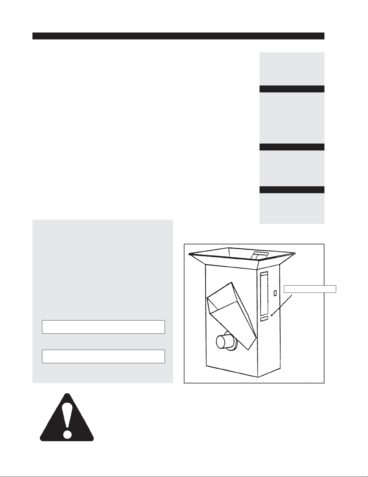
This safety alert symbol identifies important safety messages in this manual.
When you see this symbol, be alert to the possibility of personal injury and
carefully read the message that follows.
Serial Number Decal Location
Serial Number Decal
Be alert! Your Safety is Involved.
Page 3

W
ARRANTY
Chipper and Hydraulic Feed Limited Warranty
Crary Bear Cat products are warranted for two years from the date of sale to the original cumsumer purchaser
and 90 days from the date of sale to a commercial or rental operation. On models 70380, 70500, 70520,
70554, 70580, 71014, 71020, 71620, 71825, 71854, there is a 90 day warranty for commercial business or
rental use, and a two year warranty when sold to a consumer for private use. The engine is warranted by the
original manufacturer with the terms and limitations listed in the manufactures manual.
Within the above stated period, Crary Co. will replace any part(s) found to be defectiv e in material and/or
workmanship, after the receipt of the part in our plant. Labor costs to replace these defective parts will be paid
at a Crary established labor rate and time allowed (flat rate) for repair. All transportation char ges incurred in
shipping part(s) are the responsibility of the purchaser.
This warranty is void in the case of accidents, failure to perform normal maintenance, or failure to follow
those instructions listed in the service manual. This warranty is also in lieu of all other expressed warranties
and voids any implied warranty as to the merchantability or fitness of the product for a particular purpose and
of any other obligation on the part of Crary Co. Some states do not allow limitations on how long the implied
warranty lasts, so the above limitation may not apply to you.
This warranty applies only to parts or components which are defective, and does not cover necessary repair
due to normal wear, misuse, accidents, or lack of proper maintenance. This includes belts, pulleys, and
chipper blades. Regular routine maintenance of the unit to keep it in proper operating condition is the
responsibility of the owner .
All warranty repair reimbursable under the Crary Co. warranty must be performed by an authorized Bearcat
service dealer using Bearcat approved replacement parts. Repair or attempted repair by anyone other than an
authorized Bearcat service dealer is not reimbursable under the Crary Co. warranty. In addition, these
unauthorized repair attempts may result in additional malfunction, the correction of which is not covered by
warranty.
Crary Co. is not liable for indirect, incidental, or consequential damages in connection with the use of this
product including any cost or expense or providing substitute equipment or service during periods of
malfunction or non-use.
Some states do not allow the exclusion of incidental or consequential damages, so the above exclusion may not
apply to you. This warranty gi ves you specific legal rights. You may also have other rights which vary from
state to state.
Be sure to note the Chipper serial number in any correspondence with Crary Co. or any authorized Bearcat
dealer. The serial number is located on the rotor assembly cover.
Warranty
Page 4

Contents
Section 1: Safety Instructions ................................... 2
1.2 Safety Decals...................................................................................4
Section 2: Assembly, Controls, and Operation ........ 6
2.1 Assembly ......................................................................................... 5
2.1.1 Assembly, Towable Models........................................................... 5
2.1.2 Assembly, PTO Models ................................................................ 5
2.1.3 Controls & Operation..................................................................... 6
2.1.4 Starting.......................................................................................... 8
2.1.5 Specifications & Recommendations ............................................... 8
2.2 Operation..........................................................................................9
2.2.1 Shredding ...................................................................................... 9
2.2.2 Chipping ........................................................................................ 9
2.2.3 Stopping Instructions..................................................................... 9
Section 3: Service and Maintenance ....................... 10
Service & Maintenance Chart ............................................................... 10
3.1 Changing Discharge Screens ........................................................11
3.2 Sharpening Chipper Blades............................................................11
3.2.1 Chipping Blade Sharpening Tips.................................................. 11
3.2.2 Setting Chipping Blade Clearance ............................................... 12
3.3 Replacing Shredder Kit ...............................................................13
3.3.1 Clearing Plugged Rotor(Towable) ................................................ 13
3.3.2 Clearing Plugged Rotor (PTO)..................................................... 14
3.3.3 Removing Rotor .......................................................................... 14
3.3.4 Replacing Drive Belts (Towable) ................................................. 14
3.3.5 Replacing Drive Belts (PTO) ....................................................... 1 4
3.3.6 Trailer Service Tips ..................................................................... 15
3.3.7 Additional Service Tips ............................................................... 15
C
ONTENTS
Service Accessories.................................................. 15
Troubleshooting......................................................... 16
Warranty
1
Page 5

S
ECTION
1
Safety Instructions
Your safety and the safety of others is very important.
We have provided important safety messages in this
manual and on the machine. Please read these messages
carefully.
A safety message alerts you to potential hazards that
could hurt you or others. Each safety message is
preceeded by one of three words: DANGER,
WARNING, or CAUTION.
You WILL be KILLED or
DANGER
WARNING
CAUTION
SERIOUSL Y HUR T if you don't
follow instructions
You CAN be KILLED or
SERIUOLSY HUR T if you don't
follow instructions.
Y ou CAN be HUR T or DAMAGE
machine if you don't follow
instructions.
Before Operating
1. Become familiar with the owner's manual before
attempting to operate this equipment. See engine
owner's manual for additional safety information.
2. Do not allow children to operate this equipment.
3. Do not operate this equipment in the vicinity of
bystanders.
4. Carbon monoxide can be extremely dangerous in
enclosed areas; do not run the machine in an enclosed area. The exhaust from the engine contains
carbon monoxide, which is colorless, odorless, and
tasteless.
this machine wearing loose clothing particularly if it
has drawstrings which could wrap around or get
caught in the machine.
3. Operate the machine only on a level surface. Do not
operate the machine on a paved, concrete, or hard
gravel surface. Operating on a hard surface may
cause discharged material to rebound and kickback.
It will also cause increased machine vibration.
Increased vibration may cause the machine to move
and will promote premature wear of parts or loosening of fasteners.
4. Before starting the machine, visually check that all
screws, nuts, bolts, and other fasteners are properly
secured. Once every 10 hours of operation, all
screws, nuts, bolts, and other fasteners should be
checked for proper tightness to insure everything is
in proper working condition.
Operation
1. Before starting the machine, make certain that the
cutting chamber is empty .
2. When feeding chipable material into the machine, be
extremely careful to exclude pieces of metal, rocks,
bottles, cans, and other foreign objects.
3. If the cutting mechanism strikes any foreign object
or if the machine should start making an unusual
noise or vibration, immediately shut off the engine,
and allow the machine to come to a complete stop.
After machine stops:
a) Inspect for damage.
5. Do not allow hands, or any part of body or clothing,
inside the feeding chamber, dischar ge chute, or near
any moving part.
6. Before inspecting or servicing any part of the
machine, shut off the engine, and make sure all
moving parts have come to a complete stop.
Preparation
1. Obtain and wear safety glasses at all times while
operating the machine. One pair of safety glasses is
provided with each chipper .
2. A v oid wearing loose-fitting clothing. Ne v er operate
2
b) Replace or repair any damaged parts.
c) Check for and tighten any loose parts.
4. Every 10 hours of operation, check the bolts on the
following for correct torque (75 ft. lbs.):
• Chipper rotor bearing
• Chipper blades (use 5/16" bolts (20 ft lbs))
Failure to maintain proper fastening torque (75 ft.
lbs.) on bolts for the components listed above may
result in severe damage to the chipper and/or
personal injury!
Page 6

S
ECTION
1
5. Do not allow processed material to build up in the
discharge area; this may prevent proper discharge
and can result in kickback of material through the
feed opening.
6. Do not attempt to operate the chipper with any of
the guards, deflectors, or shrouds removed. Keep
away from moving parts.
7. Keep all guards, deflectors, and shrouds in good
working condition.
8. Always stand clear of the discharge area when
operating this machine.
9. Keep your face and body back from the feed opening.
10. Do not overreach. Keep proper balance and footing
at all times.
11. Do not transport or move machine while the machine is running.
12. If the machine becomes clogged, shut off engine.
Allow machine to come to a complete stop before
clearing debris.
13. On electric start models, disconnect cables from
battery before doing any inspection or service.
14. Do not tamper with the engine governor settings on
the machine; the governor controls the maximum
safe operating speed and protects the engine and all
moving parts from damage caused by over-speed.
Additional Safety Rules for PTO
Models
1. Connect 3 pt. hitch pins and snap pins, connect PTO
shaft and have leg stands downa and secure when in
use.
2. To move the unit: shut off the PTO, lift 3 pt. hitch,
and adjust leg stands if needed.
3. Keep guards and shields in place at all times while
operating. Al ways disengag e tractor PTO and shut
off engine before removing guards or shields.
4. Keep hands, feet, and clothing away from all PTO
drive parts.
5. Never clean, lubricate, or adjust the chipper/shredder when it is running.
pants when working around PTO.
7. Before starting tractor always make sure transmission is in neutral or park and PTO is disengaged.
WARNING! Recommended tractor PTO horsepower is 15
HP to 30 HP. Use of these units on tractors above 30 PTO
horsepower may cause belt and machine damage in overload
conditions.
Additional Safety Rules for Towing
1. Always connect hitch safety chains. Make sure
trailer hitch bolts are tight and secure. Do not
attempt to tow the trailer if vehicle is not equipped
with a 2" ball.
2. Maximum towing speed should not exceed 55
M.P.H. Inflate tires to manufactures specs. as stated
on the tire sidewall. Check wheel lug bolts periodically to be sure they are tight and secure.
3. Make sure that the jack stand on trailer is in the UP
position to clear the ground during towing. Place the
jack stand on a level surface and secure it in the
DOWN position before use.
4. Shut off fuel supply to engine when towng.
5. Disconnect spark plug wire when towing.
Maintenance and Storage
1. When this equipment is stopped for servicing,
inspection, storage, or to change an accessory , mak e
sure that the spark plug or PTO is disconnected.
2. Store the machine out of the reach of children and
where fuel vapors will not reach an open flame or
spark. For storage periods of three months or more,
drain the fuel and dispose of it in a safe manner.
Always allow the machine to cool before storing.
Torque Chart
Standard minimum
tightening torque for
normal assembly
applications.
Bolts (SAE GR5)
Size Ft. Lbs.
5/16" 20
3/8" 35
Size Ft. Lbs.
5/16" Set 15
#10-24 Set 3
Screws
6. Never wear loose jackets, shirts, shirt sleeves or
3
Page 7
S
ECTION
1
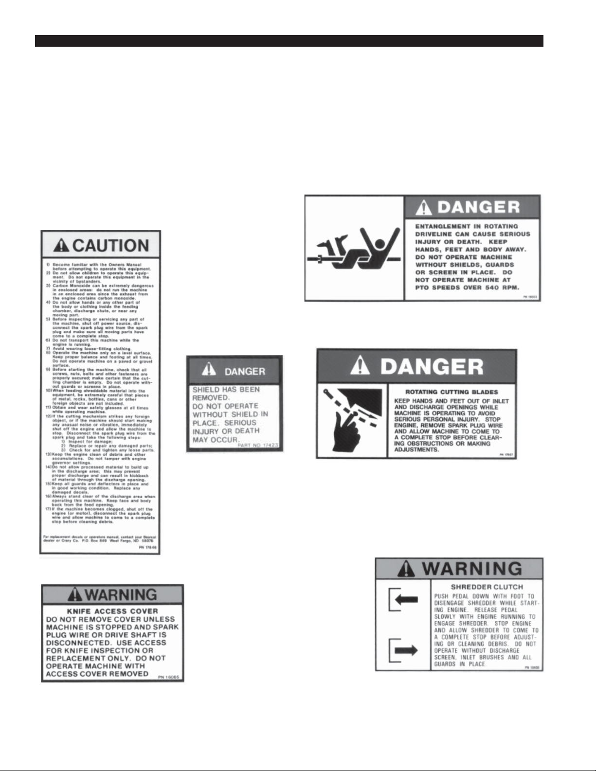
1.2 Safety Decals
Safety and instruction decals are located on the chipper frame and engine. Replace any decal that is damaged or
unreadable. For location of safety decals on the chipper frame, see parts drawings and lists in section 4.
NOTE: For engine safety and instruction decals, see engine owner's manual or contact the engine manufacturer.
Part #16033
PN 17846
Part #16085
Part #17423
Part #17837
Part #16408
4
Page 8

Assembly
S
ECTION
2
Your chipper/shredder may arrive totally or partially
assembled. If your machine arrives partially assembled,
you may need to perform the steps in this section.
2.1.1 Assembly Towable Models
1. Remove the chipper/shredder and hopper assembly
from shipping crate.
2. Place hopper assembly on top of shredder frame.
The tabs on the bottom of the hopper should be
placed inside of the shredder frame. Secure with 11
5/16" x 3/4" Bolts, washers and locknuts. Insert the
bolts from the inside of the hopper outwards.
3. Install rims and wheels onto trailer frame, using the
wheel bolts supplied.
4. Using three 5/16" x 1" bolts, six 5/16" washers, and
three 5/16" locknuts, install the fender onto the
existing fender bracket on the chipper chute side of
the unit. A washer is used on both the bolt head and
the nut in this application. Torque bolts and nuts to
20 ft. lbs.
1. Remove from crate.
2. Place hopper assembly on top of shredder frame.
The tabs on the bottom of the hopper should be
placed inside of the shredder frame. Secure with 11
5/16" x 3/4" Bolts, washers and locknuts. Insert the
bolts from the inside of the hopper outwards.
3. Connect 3 pt. mounts on chipper/shredder and
tractor (a special bushing kit is needed for category
2 & 3 hitches). Secure connection with snap rings.
4. Adjust leg stands so that the PTO drive shaft runsa
as straight as possible. PTO shaft angle should not
o
exceed 7
.
5. Connect PTO shaft between Chipper/Shredder and
tractor. Mak e sure you are using the correct RPM
machine, there are two models, 540 rpm and 2000
rpm. Do not operate machine at speeds different
than specified on shield.
5. Using three 5/16" washers and three 5/16" nylock
nuts, mount the left side fender onto the large belt
guard. There are three weld stubs on the belt guard
to which the fender is attached. Torque to 20 ft. lbs.
6. Insert trailer hitch into track on the bottom of the
trailer frame and secure with three 3/8" bolts,
washers and nuts that connect under the trailer
frame. Tighten to 35 ft. lbs. torque
7. Read and become familiar with the Engine Owners
Manual. Be sure to fill the engine oil before starting
the machine.
8. Install 12 volt battery (not supplied) into tray on
hitch assembly. Connect cables, be sure black cable
is attached to negative battery terminal and red cable
to positive terminal. Secure battery with angle and
bolt. (NOTE: Battery size-Group U1 12 v olt 32
amp-250 cold cranking amps.)
9. Connect spark plug wire.
2.1.2 Assembly PTO Model
NOTE: Minimum & maximum telescoping on the PTO shaft
is 18" to 26". This will leave a 4 inch overlap at maximum
telescoping distance.
NOTE: The maximum distance between the chipper/
shredder and the tractor should not exceed 22-1/2 inches.
2
5
Page 9

S
ECTION
2
6. Never inspect or work on PTO drive area without
first disengaging PTO and shutting off the tractor
engine.
7. Start tractor engine and engage PTO drive clutch
(refer to the tractors owner's manual). Increase
engine speed to rated PTO rpm position.
2000 RPM PTO Models
NOTE: When the tractor used has an electric PTO clutch
and brake, a different PTO shaft should be used.
1. Remove existing PTO shaft shield
2. Remove existing PTO shaft from Chipper/
Shredder.
3. Install new PTO shaft onto Chipper/Shredder.
4. Install new PTO shaft shield onto Chipper/Shredder.
5. Check slip clutch adjustment while the machine is
running to ensure it is operating correctly. Adjust if
needed.
2.1.3 Controls and Operation
Towable Models
1. Engine Throttle. Changes engine speed. (20 hp
A
There are two different
types of unclutched
PTO shaft kits available
for the 2000 RPM units.
Check the PTO end of
your tractor to determine
if you need a Male Drive
Shaft Kit (P/N 70912)
or a Female Drive Shaft
Kit (P/N 70913). There
is a Clutched PTO shaft
Kit (P/N 70885) for
tractors with electric
brake on the PTO.
1,2,3
B
D
C
4
5
7
6
6
Page 10

S
ECTION
2
engine)Turn knob clockwise for full throttle operation. T urn knob counter clockwise for idle on w arm
up. Turn knob all the way down to shut engine off.
(14 hp engine) Pull lever up for full throttle operation. Push lever down for idle on warm up. Push
lever all the down to shut engine off. Refer to
engine owners manual for further engine operating
instructions.
2. Engine Choke. Use when starting cold engine. Pull
to on position when starting. Push lever to of
position when engine is running. Refer to engine
owners manual for further operating instructions.
3. Key Switch. (Not Shown) located above recoild
starter on engine case. Activate starter switch,
release switxh as soon as the engine is running. Do
not crank starter for more than 10 seconds or
damage may result.
4. Engine Fuel Tank. Use unleaded fuel only.
DONOT MIX OIL AND GASOLINE.
5. T r ailer Hitch. Always use 2" ball and hook safety
chains to towing vehicle.
6. Jack Stand. Always have up and clear from the
ground when moving the unit. When the in use,
be sure jack stand is down and locked in position
with the snap pin.
7. Foot Pedal. Used to engage rotor drive belt.
PTO Models
1. 3 pt. Hitch Connections. Mount Chipper/Shred-
der to tractor. Connect direct for categorys 0 & 1. A
bushing kit must be installed on 3 pt. connections
for category 2 hitches.
2. PTO Shaft. Connects tractor PTO to Chipper/
Shredder Drive Shaft. Avoid angle greater than 20
0
up or down when unit is in use.
3. Leg Stands. Adjustable to allow proper driveshaft
angle. Don not move machine unless the legs clear
the ground.
4. Jackshaft. Used for correct belt tension adjustment.
Common Parts
A. Shredder Hopper. Material to be shredded are fed
through the hopper to the shredding knives.
B. Chipper Chute. Material to be chipped are fed
through the chipper chute to the chipper blades.
C. Drive Belt Shield. Never remove shield while
the unit is running.
D. Rotor Access Cover . Used to remove chipper blades
and service rotor assembly.
A
C
1
B
D
4
2
3
7
Page 11

S
ECTION
2
2.1.4 Starting(Towable Model)
Caution: Move machine to a clear, level area outdoors
before starting. do not operate machine on a paved,
concrete, or gravel surface. do not operate in the vicinity of
bystanders. Make sure cutting chamber is empty before
starting.
1. Before starting, check engine oil level and fill if
necessary. See engine owners manual for operation and maintenance instructions.
NOTE: Some oil usage is normal. Check oil level with each
use.
4
WARNING: Handle fuel (gasoline) with care. It is
highly flamable. Always use an approved
container and fill tank outdoors. Never add fuel
to a running or hot engine.
2. Before starting, fill fuel tank with fresh, clean
unleaded regular gasoline. DO NO T MIX OIL
WITH GASOLINE.
3. Disengage clutch lever by pressing foot clutch
pedal.
4. Place engine throttle lever at 3/4 - full open position.
Place engine choke lever to choke position.
NOTE: When restarting a warm engine after a short shut down
period, it may not be necessary to use full choke. If engine fails
tostart, move lever to run or partial choke.
5. Activate the starter switch. Release the key as soon
as the engine starts. Do not crank for more than 10
seconds. Repeat if necessary.
6. Move choke lever to run position after engine starts.
Some choke may be needed until engine is fully
warmed up.
7. Once engine is running and no choke is needed,
slowly let foot clutch pedal up. This will engage
the drive belt and the rotor will turn.
NOTE: If engine kills when engaging foot clutch pedal, either
use more choke or increase engine RPM. When the clutch is
engaged the foot pedal may vibrate or chake until the engine
and rotor have increased to full operating RPM.
2.1.5 Specifications &
Recommendations
The Bear Cat chipper/shredder is designed to gind,
shred, and chip a variety of materials into a more readily
decomposing or handled condition. The following
guidelines can be used to help get you started.
1. Shredding/Grinding. Small materials such as
leaves, grass clippings, and garden
debris(cornstalks, plants, vines, etc.) can easily be
processed through the shredder. Sticks and branches
should be limited to 1-/2 inches in diameter and no
longer than 24 inches long to avoid excess whipping
and wrapping. Wet materials may require use of the
coarse (large hole) or wet debris discharge screen to
avoid plugging. The processed material can be
placed in a compost pile or spread on the ground as
a mulch. The shredder can also be used to process
such materials as newspapers, plastics, aluminum
cans, milk cartons, etc. It may be necessary to use a
branch, cardboard tube, leaf tamper or similar object
to help push material through the inlet guard. When
grinding small dry matrial, use the optional fine
(small hole) discharge screen.
WARNING! Do not reach into either feeding
chamber or discharge area until engine is
stopped, spark plug wire disconnected and the
rotor has stopped turning.
2. Chipping. The chipper can be used to make chips
from branches up to 5 inches in diameter. Lar ger
branches may have to be trimmed so that the limb
will fit into the chipper chute. Several small
branches can be grouped together and fed into the
chipper chute at one time. Changing to the optional
medium discharge screen will make smalled sized
chips. The processed chips can be used as a decorative mulch or placed in a compost pile.
2.2 Operation
2.1.4 Starting(PTO Model)
1. Start tractor engine and engage PTO drive clutch
(See tractor owners manual). Increase engine speed
to reated PTO RPM position.
5
8
2.2.1 Shredding (See Figure 4)
WARNING! Always stand clear clear of the
discharge opening when operating the machine.
Keep hands or any other part of the body or
clothing out of inlet and discharge openings.
WARNING!! DUE TO THE AGRESSIVENESS OF THE
Page 12

S
ECTION
2
MACHINE'S SHREDDING CAPABILITY, DO NOT ATTEMPT
TO HOLD ON TO MATERIAL INTENDED FOR SHREDDING
ONCE IT HAS BEEN PLACED IN THE HOPPER.
1. Place materials to be shredded (grass, leaves, garden
refuse, sticks and branches less the 1-1/2 inches in
diameter and 24 inches long, etc.) into the hopper. If
necessary,
use a leaf
tamper,
branch or
other similar
object to
push material
through the
inlet guards.
Feed material evenly
into the
shredder so
that the
engine does
not lug down
or the
shredder
Figure 4
becomes
plugged.
Attempting
to use the clutch to clear a plugged rotor will cause
belt damage. Refer to Section 3, Clearing Plugged
Rotor, for instructions. Branches or items that plug
or cause the machine to stall should be fed in more
evenly or put through the chipper chute.
2.2.2 Chipping (See Figure 5)
The actual feed rate of the limb into the chipper will
depend on the type of material being fed, the
sharpness of the cutting blades and the size of the
machine. Alternately insert and retract the limb or
insert continuously at a rate that will not kill the
engine. Rotating the branch as it is being fed will
improve cutting action.
The chipping blades will dull with use and require
periodic sharpening. Refer to Section 3, Sharpening
Chipper Blades, for instructions.
Figure 5
2.2.3 Stopping(Towable Models)
To stop the machine, proceede as follows:
1. Move throttle to slow position.
2. Disengage rotor clutch by pressing foot pedal.
3. Move throttle to stop position or turn off ignition
switch and remove spark plug wire from spark plug.
4. Allow machine to come to a complete stop.
WARNING! Keep face and body away from the feed
opening. Do not overreach. Keep proper balance and
footing at all times.
1. Select limbs that are between 3/4 and 5 inches in
diameter; trim side branches off that cannot be bent
over enough to fit into the chipper chute. Some
small branches can be broken off on the chipper
chute transport handle. Small diameter branches
can be held together in a bundle and fed in
simultaneously.
2. Place limb, butt end first, into the chipper chute
until it contacts the chipping blades (See figure 5).
2.2.4 Stopping(PTO Models)
1. Move the tractor throttle to slow position.
2. Disengage the PTO lever and shut off the tractor
engine.
3. Allow the machine to come to a complete stop.
Note: The rotor is heavy and has inertia that will make the rotor
continue to turn for some time after the clutch has been
disengaged. You can tell that the rotor has come to a complete
stop when there is no noise, machine vibration, or the exposed
end of the rotor shaft is not rotating. The stopping time can be
shortened by inserting a branch into the chipper chute so it
contacts the blades and slows the rotor.
9
Page 13

S
ECTION
3
Service and Maintenance
Inspection Items
Check Nuts & Bolts(Including Wheels &
Tire Pressure)
Check
Engine Oil
Replace
Replace Spark Plug
Check
Air Filter Element
Replace Fuel Filter
Clean
Replace
Before
Each
Use
Every
10
Hours
Every
25
Hours
Every
50
Hours
*
Interval
Every
100
Hours
Every
200
Hours
Every
300
Hours
Every
800
Hours
Every
1
years
Check Sharpness of Chipper Blades
Grease Bearings and Pivots
Check Bolts: Chipper Blades
Check Drive Belt
Clean Machine
Note: (*) Service more frequently when used in dusty conditions
Before inspecting or repairing any part of the machine, shut off the engine and make sure all
moving parts have come to a complete stop.
Indicates first hours of use.
10
Page 14

Service and Maintenance
S
ECTION
3
Before inspecting or servicing any part of the
machine, shut off the engine, and make sure all
moving parts have come to a complete stop. The
chipping blades are sharp! Use care when working
on machine to avoid injury.
3.1 Removing Discharge Screen
1. Remove the discharge screen by removing the two
5/16 inch retaining bolts from the bottom of the
screen.
2. Pull the bottom of the screen outward. This will
cause the screen to rotate off the lip on top and fall.
3. To reinstall the discharge screen, place the top lip of
the screen into the slot under the top slope.
4. Rotate the screen so that the bolt holes align with
the holes in the chipper base and the plate butts
against the kicker bar.
5. Reinstall bolts and torque to proper specs.
3.2 Sharpening Chipper
Blades
The chipper blades will eventually become dull, making
chipping difficult. It is recommended that the chipper
blades are sharpened every 5-15 hours of chipper
operation. To remove the chipping blades for
sharpening:
1. Remove the discharge screen by removing the 5/16
inch retaining bolt and pulling the screen outward.
2. Romove the access cover on the chipper chute side
of the machine.
3. Rotate the rotor so that the bolts holding the chipper
blade are most accessable.
heat treated properties. Use short grinding times and
cool with water . Try to remove an equal amount off each
blade to maintain balance. Replace the chipping blades
and tighten bolts to 20 ft. lbs.
NOTE: Never sharpen or grind on the back side of the
chipper blade. This will cause the edge to roll and the
chipping blade will be damaged, causing poor chipping and
feeding of material. Small imperfections, nicks, burrs, etc.
on the flat side of the blade will not affect performance of
the machine.
3.2.1 Chipping Blade Sharpening
Tips
Poor chipping performance is usually a result of dull
chipping blades. If your chipper's performance has
decreased, check for the following symptoms:
• Severe vibration when feeding material into the
chipper.
• Small diameter branches do not self-feed.
• Chips discharge unevenly or have stringy tails–
especially when chipping green branches.
Before you sharpen the chipping blades, check for
permanent damage. Replace the blade if:
• The blade is cracked (especially around the bolt
holes) or the edges are too deeply chipped to be
ground smooth.
• The base of the cutting edge is worn or has been
re-sharpened so that it is too close to the rotor
chipping slot.
4. Remove the two hex head bolts holding the blade
itself. Repeat for all four blades.
Grind the angled edge of the chipping blade to 45
degrees (see figure 6): Grind the blades on a slow-speed
wet grinder if possible, or have them sharpened by a
professional. If you use a bench grinder, be careful when
grinding so that the blade material does not get too hot
and change color–this will remove the blade's special
6
45
0
11
Page 15

S
ECTION
3
3.2.2 Setting Chipping Blade
Clearance
The chipping blades should clear the chipper block
located directly under the chipper chute by 1/16 inch to
1/8 inch. To adjust the blade clearance, proceede as
follows:
1. Remove the lower belt guard, the discharge screen
and the access cover.
2. Loosen the bushing bolts holding the pulley to the
rotor shaft on the front side.
3. Remove the cover cap on rotor shaft rear side.
4. Use a punch and hammer to to tap the lock collars in
a direction opposite of normal rotation so that they
rotate and can be removed.
5 . Using a rubber mallet tap the end of the rotor
shaft to obtain 1/16 to 1/8 of an inch clearance (See
figure 7). The blade clearance can be viewed
through the discharge opening. Rotate the rotor and
check the cleanance on both chipping blades.
6. Once clearance has been set, the lock collars must
be replaced to retain setting. Slip the lock collars
over the eccentric hub on the bearings. Using a
punch and a hammer, rotate the lock collars in the
direction of shaft rotation (i.e. clockwise on the rear
bearing and counter-clockwise on the front bearing)
and "set" them with a positive hammer tap. Tighten
the lock collar set screws.
7. Loosen the bushing holding the belt pulley on the
rotor shaft. Move the pulley on the shaft so it is
aligned directly below the similar pulley on the
engine shaft (the pulley should be moved an
equal but opposite amount the rotor was moved).
8. Replace the lower belt guard, discharge screen, and
rotor shaft cover.
12
7
Page 16

S
ECTION
3
3.3 Replacing Shredder Kit
Care must be taken to insure knives and spacers are
installed properly to maintain rotor balance.
1. Remove discharge screen cov er , dischar ge screen
and rear side access cover.
2. Remove #10-24 nuts and bolts from the knife shafts.
3. Align shaft with access hole in rear of frame.
4. Using a small punch or rod, drive the shaft towards
the access hole.
5. Remove spacers and shredder knives. Be carefull to
keep track of the order the spacers were installed on
the shafts so they can be returned to the original
locations. Reverse or replace knives and reassemble
back onto the rotor. Install a ne w #10-24 nut and
bolt.
6. Repeat steps #3 through #5 to assemble the other
three shafts.
NOTE: Never reuse rotor shafts or bolts and nuts if they
show signs of wear or abuse. Install new ones.
3.3.1 Cleaning Plugged Rotor
(Towable Models)
WARNING! If the machine becomes plugged, shut off the
engine, disconnect the spark plug wire and allow the
machine to come to a complete stop before clearing debris.
Do not operate machine without proper guards and
screens in place.
1. Stop engine, disengage rotor clutch and allow
machine to come to a complete stop. Remove the
spark plug wire.
2. Remove the discharge screen in place.
3. Clean the debris out of the shredding rotor. Turn the
rotor by hand to be sure it is free to rotate.
4. Replace discharge screen.
8
13
Page 17

S
ECTION
3
5. Replace spark plug wire, restart engine and resume
operation.
3.3.2 Cleaning Plugged Rotor (PTO
Models
Do not operate machine without proper guards and
screens in place.
1. Disengage PTO and shutoff tractor engine.
2. Remove the discharge screen.
3. Clean the debris out of the shredding rotor. Turn
the rotor by hand to be sure it is free to rotate.
4. Replace discharge screen.
5. Start tractor, engage PTO and resume operation.
3.3.3 Removing Rotor
Do not operate machine without proper guards and
screens in place.
1. Remove the discharge screen, belt guards and the
rotor shaft end cover.
Models)
Check the condition of the drive belts annually or every
30 hours of operation, whichever comes first. If the belt
is cracked, frayed or worn, it should be replaced. To
replace the belt, proceed as follows:
1. Depress the foot clutch pedal. Shut off the engine
and remove the spark plug wire.
2. Remove the large belt guard.(4-5/26" Bolts)
3. Remove the inner belt guide from under the drive
belt.
4. Disconnect and plug the fuel line from the fuel tank.
Remove the fuel tank from the frame assembly.
5. Adjust for correct belt tension by loosening the four
bolts the mount the engine to the frame and slidding
the engine forward as much as possible.
6. T o rque engine mount bolts, replace fuel tank and
reconnect fuel line.
7. Install lower belt guide and start the engine to test if
belt is tensioned correctly. If the belt continues to be
loose, it will have to be replaced.
2. Loosen the bushing bolts holding the drive pulley to
the shaft and remove the pulley.
3. Loosen the set screw in the lock collars. Using a
punch and hammer, tap the lock collars in a direction opposite of normal rotation so that they can be
removed.
4. Loosen the set screw in the center of the rotor
assembly.
5. Remove the two 3/8x2-1/2" bolts running through
the rotor shaft.
6. Using a rubber mallet or other soft hammer, drive
the shaft towards the chipper chute side of the
machine.
7. Once the shaft has been removed, the rotor assembly
can be taken from the chamber through the discharge opening.
8. To ease reinstallation, smooth any divots or marks in
the shaft caused by the set screws. Clean shaft as
much as possible before installing into machine.
3.3.4 Replacing Drive Belts (Towable
8. Replace large belt guard and resume operation.
9. To replace the drive belt,
1. Remove the large belt guard and lower belt guide.
2. Lift belt idler pulley off the belt and remove the
belt from the pulleys.
3. Install a new belt onto the pulleys and lower belt
idler. Check belt tension before start-up. Install the
lower belt guide.
4. Install the large belt guard and resume oepration.
3.3.5 Replacing Drive Belts (PTO
Models)
Check the condition of the drive belts annually or
every 30 hours of operation, whichever comes first.
If the belt is cracked, frayed or worn, it should be
replaced. To replace the belt, proceed as follows:
1. Disengage PTO and shut off tractor engine.
2. Remove PTO shaft from tractor and disconnect
machine from 3 pt. hitch.
14
Page 18

S
ECTION
3
3. Remove the round shield connected to the belt guard
the covers the PTO shaft by removing the two 5/16"
nuts.
4. Remove the PTO shaft from the chipper/shredder by
loosening the two set screws and pulling the shaft
off.
5. Loosen the bolts mounting the jack shaft pillow
blockand move the shaft towards the frame so belts
can be removed.
6. Install new belts and make sure pulleys are alligned
to within 1/16". If not adjust pulleys.
7. Slide jack shaft away from frame. Tighten bolts so
that 1/4" deflection at center of belt span is obtained
with 10 lb. force applied at the center of the span.
Make sure the jack shaft is aligned parallel to the
rotor shaft before tightening the pillow block bolts.
8. Reinstall belt shields and guards. Install PTIO shaft
and tighten the two set screws. install pTO shield.
Never run PTo without all sjields in place.
3.3.6 Trailer Service Tips
1. Check wheel bolt torque every 10 hours of towing
use.
2. Check air pressure in tire every 10 hours. Fill to 60
PSI.
3. Check and repack wheel bearings with grease every
year.
3.3.7 Additional Service and
Maintenace Tips.
1. Service engine according to engine owners manual.
2. Every 10 hours of operation, all bolts and other
fasteners should be checked for correct torque.
3. The PTO model has 2 greasable bearings on the
rotor shaft. There are also two greasable bearings
on the main jack shaft under the small belt guard.
These bearing need only to be greased once per year
under normal working conditions. Be carefull not to
damage seals on the brearing by over greasing.
4. The PTO shaft also has 4 grease zerks that can be
lightly greased every 50 hours of use.
5. Remove the discharge screen (all models) daily to
avoid material buildup under normal mounting
surfaces. Clean away material and reinstall screen.
3.4 Service Accessories
Description Part Number
Towable PTO
Discharge Screens
Fine 70703 70703
Medium 70531 70531
Coarse 70332 70332
Wet Debris Screen 70559 70559
Goggles (One pair supplied with machine) 17842 17842
Maintenance Kit (Includes spark plug, air filer, oil filter, v-belt) 14 hp 70452
Maintenance Kit (Includes spark plug, air filer, oil filter, v-belt) 20 hp 71043
Leaf Tamper 70649 70649
Tool Steel Chipper Blades (Set of 4) 70453 70453
Shredder Kit 70972 70456
Light Kit 70454 70454
Collection Bag 17854 17854
Spark Plug 16069
2000 PTO Male Chuted Drive Shaft 70885
2000 PTO Male Drive Shaft 70912
2000 PTO female Drive Shaft 70913
3 pt. Hitch Bushing Kit, Category 2 16022
15
Page 19

Troubleshooting
T
ROUBLESHOOTING
Problem
1. Engine will not start
2. Engine or rotor stalls
or stops
3. Hard to feed Chipper
requires
excessive power
required
4. Shredder requires
excessive power or
stalls
Probable Cause
a) Improper control
settings
b) Lack of fuel
c) Internal Problems
a) Obstructed
discharge
b) Plugged Rotor
a) Obstructed
discharge
b) Improper blade
clearance
c) Dull chipper blades
a) Obstructed
discharge
b) Plugged rotor
c) Green material will
not discharge
Suggested
Remedies
a) Use proper setting
b) Fill fuel tank
c) See your dealer
a) Use branch or
similar object to
clear discharge
b) Clear Rotor
a) Use branch or
similar object to
clear discharge
b) Adjust clearance
c) Sharpen blades
a) Use branch or
similar object to
clear discharge
b) Clear rotor, feed
material into
shredder more
evenly.
c) Alternately feed dry
material, or install
coarse discharge
screen or wet debris
screen.
Reference
Engine Manual
Section 3
Section 3
Section 3
5. Engine stalls or belt
squeals when
engaging clutch
6. Material from
chipper wraps
around rotor shaft
16
a) Engaging clutch too
fast
b) Plugged Rotor
a) Stringy, green
material bypasses
chipper blades
b) Improper blades
clearance
c) Plugged discharge
screen
a) Lift clutch lever
more slowly
b) Clear rotor
a) Rotate branch or
material when
feeding to cut
completely
b) Adjust clearance
c) Install wet debris
discharge screen
Section 3
Section 3
Page 20

Declaration of Conformity
The undersigned manufacturer:
Crary Industries, Inc.
237 NW 12
P.O. Box 849
West Fargo, ND 58078-0849
Declares that hereunder specified unit:
CHIPPER SHREDDER
Brand: Crary Bear Cat
Type: PTO driven Chipper/Shredder
Model Number: 70554S
Complies with the requirements of:
Machinery Directive 2006/42/EC
Garden equipment-Integrally power shredders/chippers-Safety EN13683:2003 + A3 2009
EN ISO 12,100, Part 1-Safety of Machinery-Basic Conce pt s, General Principles for Design
Noise Emissions Directive 2000/14/EC
-Conformity Assessment Procedure: Annex V
(Use of harmonized standard EN ISO 3744:2010)
Sound Pressure Level: 99 dB L
Guaranteed Sound Power Level: 113 dB LWA
70554S Serial number X00117 and up
West Fargo, ND 58078-0849
June 29, 2011
CRARY INDUSTRIES, INC. The authorized representative in Europe who is authorized to
compile the technical file:
Company: Atlantic Bridge Limited
Address: Atlantic House, PO Box 4800
Earley, Reading RG5 4GB, United Kingdom
______________________________
Arlan Mathias Mr. Phillip Wicks
Senior Project Engineer
PA
th
Street
Data contained in this document pertains only to machines sold in areas that require CE compliance
standards. To identify if your machine is CE compliant, it will have the following CE mark decal:
Page 21

HEALTH WARNING
GASOLINE, DIESEL, AND
OTHER PETROLEUM PRODUCTS
Harmful or fatal if swallowed.
Long-term exposure to vapors has caused cancer in
laboratory animals.
• Avoid prolonged breathing of vapors.
• Keep face away from nozzle and gas tank/container
opening.
• Never siphon by mouth.
Failure to use caution may cause serious injury or illness.
WARNING
CHEMICALS KNOWN TO THE STATE OF CALIFORNIA TO CAUSE CANCER, BIRTH DEFECTS, OR
OTHER REPRODUCTIVE HARM ARE FOUND IN
GASOLINE, DIESEL, CRUDE OIL, AND MANY O THER
PETROLEUM PRODUCTS AND THEIR V APORS, OR
RESULT FROM THEIR USE.
READ AND FOLLOW LABEL DIRECTIONS AND USE
CARE WHEN HANDLING OR USING ALL PETROLEUM PRODUCTS.
ENGINE EXHAUST FROM THIS PRODUCT CONT AINS CHEMICALS KNO WN T O THE ST ATE OF CALIFORNIA TO CAUSE CANCER, BIRTH DEFECTS, OR
OTHER REPRODUCTIVE HARM.
Box 849
West Fargo, ND 58078
(701) 282-5520 (800) 247-7335
FAX: (701) 282-9522
 Loading...