

Page 1
OWNER
OPERATORS
MANUAL
Crary Company
A Division of TerraMarc Industries
237 12th St. NW • P.O. Box 849
West Fargo, ND 58078-0849
(701)282-5520 • FAX: (701)282-9522
www.bearcatproducts.com
3 Inch Chipper
Shredders
Models
70050 & 70050S
3 Chipper Shredder
w/ 5.5 HP Briggs & Stratton
Intek Engine
70080 & 70080S
3 Chipper Shredder w/ 8 HP
Briggs & Stratton Engine
70085
3 Chipper Shredder w/ 8 HP
Briggs & Stratton Engine &
Electric Start
70180 & 70180S
3
Chipper Shredder w/ 8 HP
Briggs & Stratton Industrial
Commercial Engine
70380 &70380S
3 Chipper Shredder
w/ 8 HP Honda Engine
70385
3 Chipper Shredder w/ 8 HP
Electric Start Honda Engine
70580 & 70580S
3 Towable Chipper
Shredder
www.terramarc.com
Manual P/N 14846-00
Rev. 01/04
Companion to P/N 14849-00
Page 2
Before you Begin
DEAR BEAR CAT CUSTOMER,
Thank you for purchasing a Crary Bear Cat Chipper Shredder. The Bear Cat Chipper Shredder
is designed, tested, and manufactured to give years of dependable performance. To keep your
Chipper Shredder operating at peak efficiency, it is necessary to adjust it correctly and make
regular inspections. The following pages will assist you in the operation and maintenance of
your machine. Please read and understand this manual before operating the chipper.
If you have any questions or comments about this manual, please call us toll-free at 1-800-247-
7335.
If you have any questions or problems with your chipper, please call or write your local factoryauthorized Bear Cat dealer.
PLEASE SEND US YOUR WARRANTY CARD
A warranty card is included in your owner's kit packaged with your chipper shredder. Please
take the time to fill in the information requested on the card. When you send your completed
card to us, we will register your machine and start your coverage under our limited warranty.
How to Contact
Bear Cat
A
DDRESS
Crary Bear Cat
237 NW 12th Street
PO Box 849
West Fargo, ND 58078
P
HONE
800-247-7335
701-282-5520
Fax: 701-282-
9522
E
MAIL
opesales@crary.com
service@crary.com
EMISSION INFORMATION
WARNING
WARNING TO ALL CALIFORNIA
AND OTHER STATES OPERATING
OUTDOOR POWER EQUIPMENT
Under California Law and under the
laws of several other states you are
not permitted to operate an internal
combustion engine using hydrocarbon
fuels on any forest covered, brush
covered or grass covered land or on
land covered with grain hay or other
flammable agricultural crop, without an
engine spark arrester in continuous
effective working order.
The engine on your power equipment,
like most outdoor power equipment, is
an internal combustion engine that
burns gasoline, a hydrocarbon fuel.
Therefore, your power equipment must
be equipped with a spark arrester
muffler in continuous effective working
order. The spark arrester must be
attached to the engine exhaust system
in such a manner that flames or heat
from the system will not ignite
flammable material.
Failure of the owner/operator of the
equipment to comply with this
regulation is a misdemeanor under
California law, and may also be a
H
OURS
M-F, 8 a.m. to 5
p.m. Central Time
violation of other state and or federal
regulations, laws, ordinances, or
codes. Contact your local fire marshal
or forest service for specific information
about what regulations apply in your
area.
The standard muffler installed on the
Bear Cat engines is not equipped with
a spark arrester. One must be added
before use if this machine is intended
to be used in an area where a spark
arrester is required by law. Contact
the local authorities if these laws apply
to you. See your authorized engine
dealer for spark arrester options.
Page 3
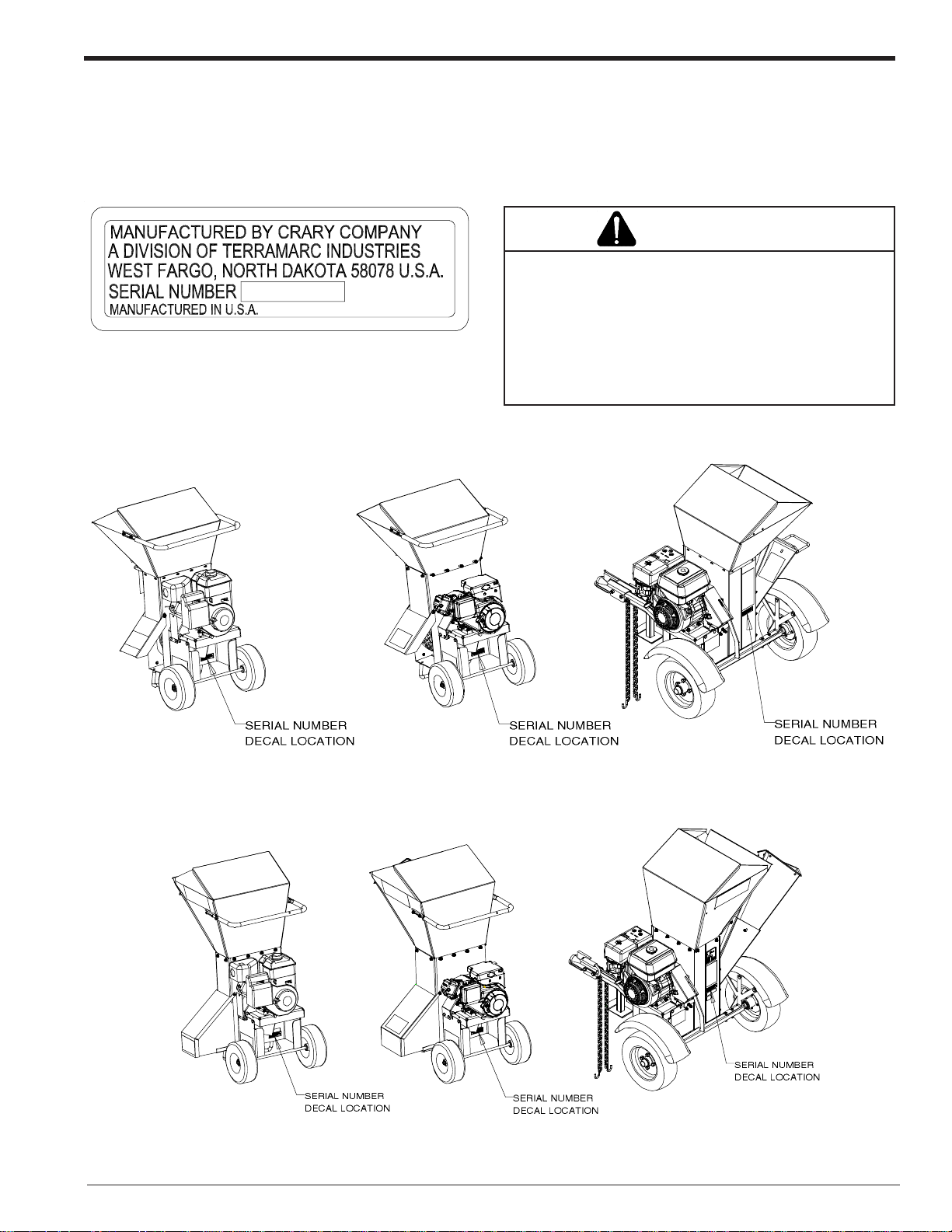
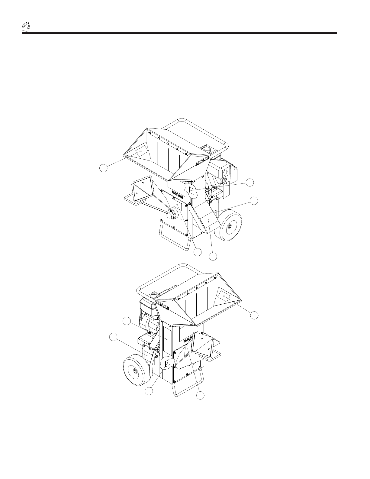
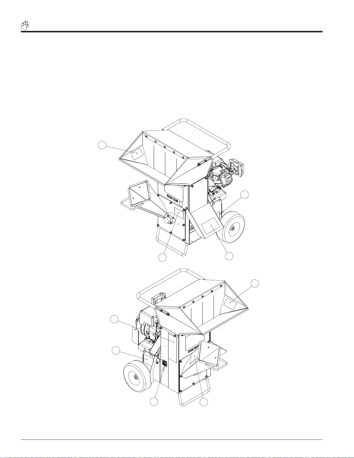
SERIAL NUMBER LOCATION
Always give your authorized Bear Cat dealer the serial number of your Crary Bear Cat Chipper Shredder when ordering
parts, requesting service or any other information. The serial number decal for Model # 70050(S) is located at the rear of the
machine (See Fig. # 2). The serial number decal for Model # 70080(S), 70085, 70180(S), 70380(S) & 70385 is located at the
rear of the machine (See Fig. # 3). The serial number decal for Model # 70580(S) is located at the left, rear of the machine
(See Fig. # 4). Please record the serial number in the space provided below and on the warranty and registration card.
WARNING
T o prevent personal injury or property damage: Shut
YXXXXX
Fig. # 1 Serial number decal
Serial Number ________________________
off engine, disconnect spark plug wire, remove ignition
key, disconnect the PTO driveline from the source
providing power or disconnect the driveline from the
chipper shredder and make sure that all moving parts
have come to a complete stop, before obtaining serial
number, servicing, adjusting or repairing.
Fig. # 2 Serial number decal location (Model
# 70050)
Fig. # 5 Serial number decal location
(Model # 70050S)
Fig. # 3 Serial number decal location (Model
# 70080, 70085, 70180, 70380 & 70385)
Fig. # 6 Serial number decal location
(Model # 70080S, 70180S, 70380S)
Bear Cat Chipper Shredder Operator’s Manual
Fig. # 7 Serial number decal location (Model
Fig. # 4 Serial number decal location (Model
# 70580)
# 70580S)
I
Page 4

Contents
Section Description Page
SAFETY ....................................................................................................................................2
BEFORE OPERA TING ................................................................................................................ 2
OPERA TION SAFETY .................................................................................................................3
TOWING SAFETY (MODEL 70580 & 70580S)............................................................................. 4
BA TTERY SAFETY (MODEL 70385 & 70085) .............................................................................5
MAINTENANCE AND STORAGE SAFETY.................................................................................. 5
SAFETY DECAL LOCA TIONS (MODEL 70050) ...........................................................................6
SAFETY DECAL LOCA TIONS (MODEL 70080, 70085, 70180, 70380, 70385) .............................8
SAFETY DECAL LOCA TIONS (MODEL 70580) ......................................................................... 10
SAFETY DECAL LOCA TIONS (70050S) .................................................................................... 12
SAFETY DECAL LOCA TIONS (70080S, 70180S, 70380S) ........................................................ 14
SAFETY DECAL LOCA TIONS (70580S) .................................................................................... 16
ASSEMBLY ..................................................................................................................................18
ASSEMBL Y INSTRUCTIONS INST ALLING THE HANDLE.......................................................... 18
ASSEMBL Y INSTRUCTIONS INST ALLING THE HOPPER......................................................... 19
INST ALLING THE CHIPPER CHUTE EXTENSION .....................................................................20
INST ALLING THE WIDE AND NARROW DISCHARGE ASSEMBL Y..........................................21
INST ALLING THE WHEELS, JACK AND HITCH ........................................................................ 22
ADDING MOTOR OIL TO ENGINE (ALL MODELS) ...................................................................23
INST ALL THE BA TTERY (MODELS 70385 & 70085).................................................................. 23
FEA TURES & CONTROLS ........................................................................................................................ 24
FEA TURES AND CONTROLS IDENTIFICATION (70050(S) - 70385(S))...................................... 24
DESCRIPTION OF OPERA TION ................................................................................................ 24
USE OF CONTROLS................................................................................................................. 25
FEA TURES AND CONTROLS IDENTIFICATION (70580 - 70580S)............................................. 26
DESCRIPTION OF OPERA TION ................................................................................................ 26
USE OF CONTROLS................................................................................................................. 27
OPERATION ..................................................................................................................................28
FILLING THE T ANK ...................................................................................................................28
ST ARTING ELECTRIC MODELS................................................................................................ 29
ST ARTING RECOIL MODELS.................................................................................................... 29
STOPPING THE CHIPPER/SHREDDER ................................................................................... 29
CHIPPING GUIDE...................................................................................................................... 30
SHREDDING GUIDE ................................................................................................................. 30
CHANGING THE DISCHARGE SCREEN................................................................................... 31
CLEARING THE MACHINE OF A PLUGGED ROTOR ............................................................... 31
SERVICE & MAINTENANCE .....................................................................................................................32
MAINTENANCE SCHEDULE ..................................................................................................... 32
SHARPENING CHIPPER BLADES............................................................................................ 33
SETTING CHIPPING BLADE CLEARANCE ............................................................................... 34
GREASING ...............................................................................................................................35
REPLACING THE SHREDDER KNIVES.................................................................................... 36
BEL T GUIDE ADJUSTMENTS ...................................................................................................37
REMOVING ROTOR.................................................................................................................. 38
REPLACING DRIVE BEL TS....................................................................................................... 38
TRAILER SERVICE TIPS........................................................................................................... 38
ADDITIONAL SERVICE AND MAINTENANCE TIPS ..................................................................38
TROUBLESHOOTING................................................................................................................39
SPECIFICATIONS ..................................................................................................................................41
BOL T TORQUE REQUIREMENTS............................................................................................. 44
SPECIAL TORQUE REQUIREMENTS....................................................................................... 45
Bear Cat Chipper Shredder Operator’s ManualII
Page 5
Chipper Limited Warranty
Crary Bear Cat Chipper Shredders are warranted for two years from date of sale for consumers and 90 days
from the date of sale for commercial or rental operations.
Within the above stated period, Crary Co. will replace any part(s) found to be defective in material and/or
workmanship, after the receipt of the part in our plant. Labor costs to replace these defective parts will be
paid at a Crary established labor rate and time allowed (flat rate) for repair. All transportation charges
incurred in shipping part(s) are the responsibility of the purchaser.
This warranty is void in the case of accidents, failure to perform normal maintenance, or failure to follow
those instructions listed in the service manual. This warranty is also in lieu of all other expressed warranties
and voids any implied warranty as to the merchantability or fitness of the product for a particular purpose
and of any other obligation on the part of Crary Co. Some states do not allow limitations on how long the
implied warranty lasts, so the above limitation may not apply to you.
This warranty applies only to parts or components which are defective, and does not cover necessary
repair due to normal wear, misuse, accidents, or lack of proper maintenance. This includes, but is not
limited to, belts, pulleys, bearings, shredder knives, and chipper blades. Regular routine maintenance of
the unit to keep it in proper operating condition is the responsibility of the owner.
All warranty repair reimbursable under the Crary Co. warranty must be performed by an authorized Bear
Cat service dealer using Bear Cat approved replacement parts. Repair or attempted repair by anyone other
than an authorized Bear Cat service dealer, or repairs using parts not approved by Bear Cat are not
reimbursable under the Crary Co. warranty. In addition, these unauthorized repair attempts may result in
additional malfunction, the correction of which is not covered by warranty.
Crary Co. is not liable for indirect, incidental, or consequential damages in connection with the use of this
product including any cost or expense or providing substitute equipment or service during periods of
malfunction or non-use.
Some states do not allow the exclusion of incidental or consequential damages, so the above exclusion
may not apply to you. This warranty gives you specific legal rights. You may also have other rights which
vary from state to state.
Be sure to note the chipper serial number in any correspondence with Crary Co. or any authorized Bear
Cat dealer.
Crary Company
A Division of TerraMarc Industries
237 12th St. NW • P.O. Box 849
West Fargo, ND 58078-0849
(701)282-5520 • FAX: (701)282-9522
www.bearcatproducts.com
www.terramarc.com
Bear Cat Chipper Shredder Operator’s Manual
III
Page 6

NOTES
Page 7
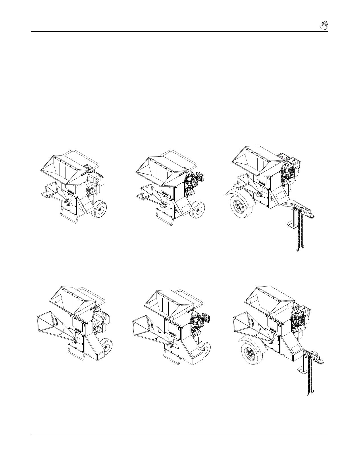
Models
70050/70050S - 3 Chipper Shredder w/ 5.5 HP Briggs & Stratton Intek Engine
70080/70080S - 3 Chipper Shredder w/ 8 HP Briggs & Stratton Engine
70085 - 3 Chipper Shredder w/ 8 HP Briggs & Stratton Engine & Electric Start
70180 /70180S - 3 Chipper Shredder w/ 8 HP Briggs & Stratton Industrial Engine
70380/70380S - 3 Chipper Shredder w/ 8 HP Honda Engine
70385 - 3 Chipper Shredder w/ 8 HP Electric Start Honda Engine
70580/70580S - 3 Towable Chipper Shredder w/ 8 HP Honda Engine
MODEL 70050 MODEL 70080
MODEL 70085
MODEL 70180
MODEL 70380
MODEL 70385
MODEL 70050S
MODEL 70080S
MODEL 70180S
MODEL 70380S
MODEL 70580
MODEL 70580S
Page 1Bear Cat Chipper Shredder Operator’s Manual
Page 8
1
Safety
Section
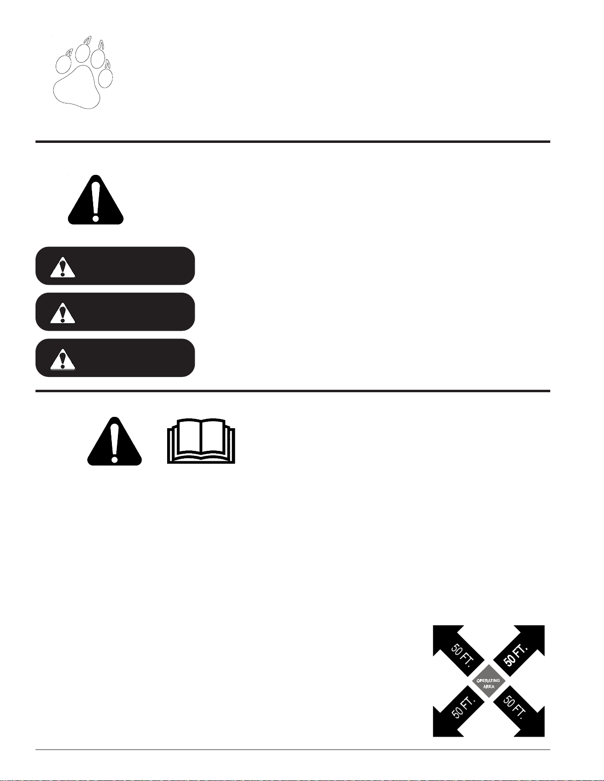
THE SAFETY ALERT SYMBOL
The Owner / Operator’s Manual and your machine uses this symbol to alert you of potential
hazards. Whenever you see this symbol, read and obey the safety message that follows it.
Failure to obey the safety message could result in personal injury, death or property damage.
Indicates an imminently hazardous situation that, if not avoided, will result in
DANGER
WARNING
death or serious injury.
Indicates a potentially hazardous situation that, if not avoided, could result in
death or serious injury.
CAUTION
Indicates a potentially hazardous situation that, if not avoided, may result in
minor or moderate injury.
BEFORE OPERATING
1. Read this Owner / Operator’s manual and the separate
Engine Owner’s manual carefully before operating this
equipment. Be completely familiar with the controls
and the proper use of this equipment.
2. Before inspecting or servicing any part of the machine,
stop engine, wait for all parts to stop moving, and disconnect spark plug wire.
Be aware that rotating blades slow down gradually after
shutting off the engine.
3. Keep safety decals clean and legible. Replace missing
or illegible safety decals.
4. Familiarize yourself with all of the safety and operating
decals on this equipment and on any of it’s attachments
or accessories.
5. Do not allow children or any person unfamiliar with the
use of the unit to use this machine.
ence of alcohol, medications, or substances that can
affect your vision, balance, and judgement. Do not operate if tired or ill. You must be in good health to operate this machine safely.
7. Do not run this equipment in an enclosed area. Engine
exhaust contains carbon monoxide gas, a deadly poison that is odorless, colorless, and tasteless. Do not
operate this equipment in or near buildings, windows,
or air conditioners.
8. Always use an approved fuel container. Do not remove
gas cap or add fuel when engine is running. Add fuel to
a cool engine only.
9. Do not fill fuel tank indoors. Keep open flames, sparks,
smoking materials, and other sources of combustion
away from fuel.
10. Keep the area of operation clear of all persons,
particularly small children. Keep bystanders
at least 50 feet (15
meters) away from the
area of operation
6. Do not operate this machine if you are under the influ-
Page 2 Bear Cat Chipper Shredder Operator’s Manual
Page 9
Safety
BEFORE OPERATING
11. Use only in daylight or good artificial light.
12. Never use without proper guards in place.
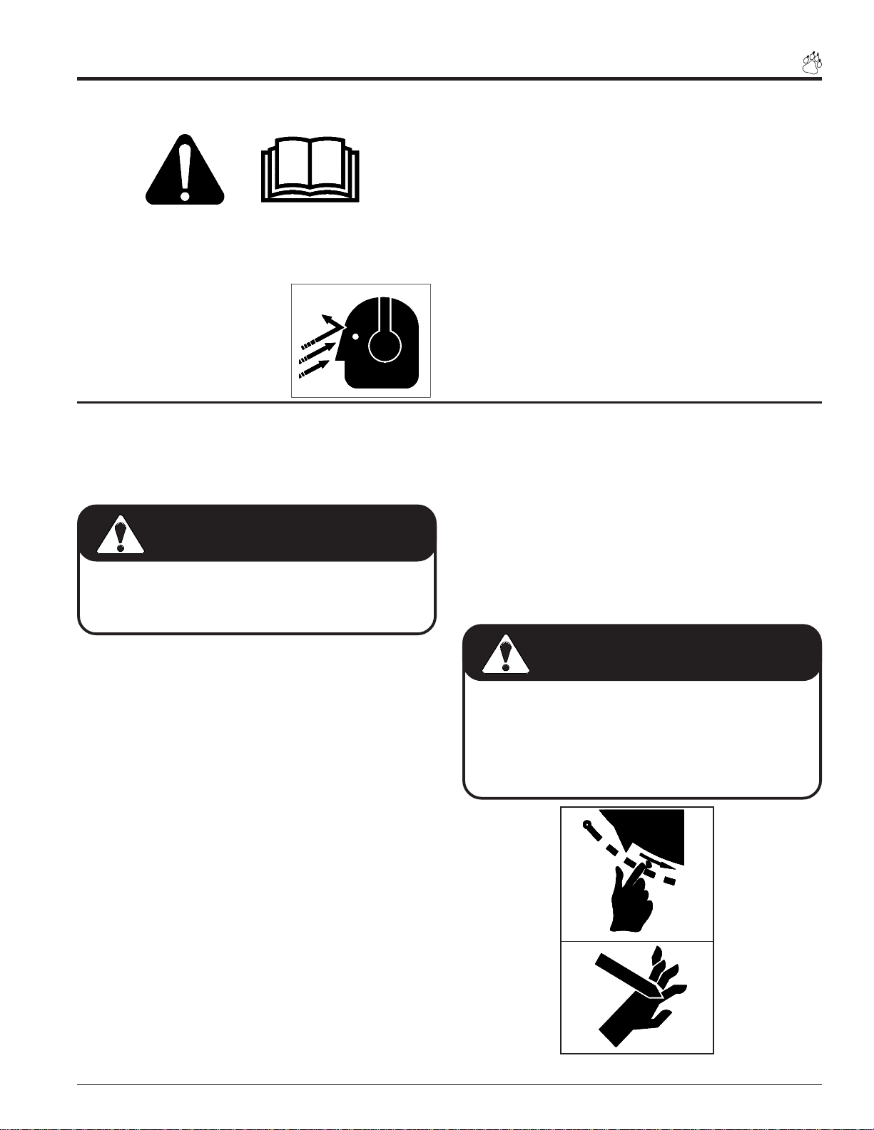
13. Wear safety glasses at all
times while operating this
machine. One pair of safety
glasses is provided.
14. Avoid wearing loose fitting
WRONG
OPERATION SAFETY
1. Do not allow hands, or any part of body or clothing,
inside the feeding chamber, discharge chute, or near
any moving parts (see Figure #8).
clothing. Never operate this machine wearing clothing with drawstrings that could wrap around or get
caught in the machine.
15. Check that all screws, nuts, bolts, and other fasteners are properly secured before starting the machine.
Check all screws, nuts, bolts, and other fasteners for
proper tightness to ensure everything is in proper working condition once every 10 hours of operation.
16. Keep all guards, deflectors, and shields in place and
in good working condition.
17. Do not transport or move machine while it runs.
6. Stand clear of the discharge area when operating this
machine.
7. Keep your face and body back from the feed opening.
DANGER
Keep hands, feet and clothing out of inlets and discharge
openings while operating this machine to avoid serious
personal injury.
2. Check the cutting chamber to verify it is empty before
starting the machine.
3. Exclude pieces of metal, rocks, bottles, cans, and other
foreign objects when feeding chipable material into the
machine.
4. Shut off engine immediately if the cutting mechanism
strikes any foreign object or the machine starts making
an unusual noise or vibrating. Allow the machine to stop
completely. After machine stops:
A. Shut off engine
B. Remove spark plug wire.
C. Inspect for damage.
D. Replace or repair any damaged parts.
E. Check for and tighten any loose parts.
8. Do not climb onto chipper shredder feed chutes or frame
when operating. Do not overreach. Keep proper balance
and footing at all times.
9. Keep the engine clear of debris and other accumulations.
WARNING
Material can kickup or shift suddenly and cause serious
injury or death.
• Wear eye, and hearing protection.
• Stand to the side of the feed chute.
• Release and stand away from the material after feed
roller starts pulling material into chipper or shredder.
WRONG
5. Do not allow processed material to build up in the discharge area; this may prevent proper discharge and can
result in kickback of material through the feed opening.
WRONG
Figure #8
Page 3Bear Cat Chipper Shredder Operator’s Manual
Page 10

Safety
10. Do not tamper with the engine governor settings on
the machine; the governor controls the maximum safe
operating speed and protects the engine and all moving parts from damage caused by over speed.
11. Set up your chipping site so as to not endanger the
public.
12. Check the bolts correct torque every 10 hours of operation (See torque chart in rear).
13. Shut off engine and allow machine to stop completely
before clearing debris if the machine becomes
clogged.
14. On electric start models, disconnect cables from battery before doing any inspection or service.
TOWING SAFETY (MODEL 70580/70580S)
15. Rotate the discharge tube to face the opposite direc-
WARNING
Failure to maintain proper fastening torque (20 ft. lbs.)
on chipper blade bolts may result in severe damage to
the chipper and / or personal injury.
tion of the towing vehicle before towing. This prevents
the discharge tube from projecting over the trailer wheels
and striking foreign objects.
1. Connect hitch safety chains. Tighten and secure trailer
hitch bolts. Do not attempt to tow the trailer if vehicle is
not equipped with a 2” ball.
2. Maximum towing speed is 45 MPH. Inflate tires to manu-
facturers specs as stated on the tire sidewall. Check
wheel lug bolts periodically to ensure they are tight and
secure.
3. Place the jack stand on the trailer in the UP position to
clear the ground while towing. Place the jack stand on a
level surface and secure it in the DOWN position before
use.
4. Never allow passengers to ride on the chipper chute while
moving the vehicle, whether the chipper is running or not.
5. Shut off fuel supply to engine when towing.
6. Disconnect spark plug wire when towing.
Page 4 Bear Cat Chipper Shredder Operator’s Manual
Page 11
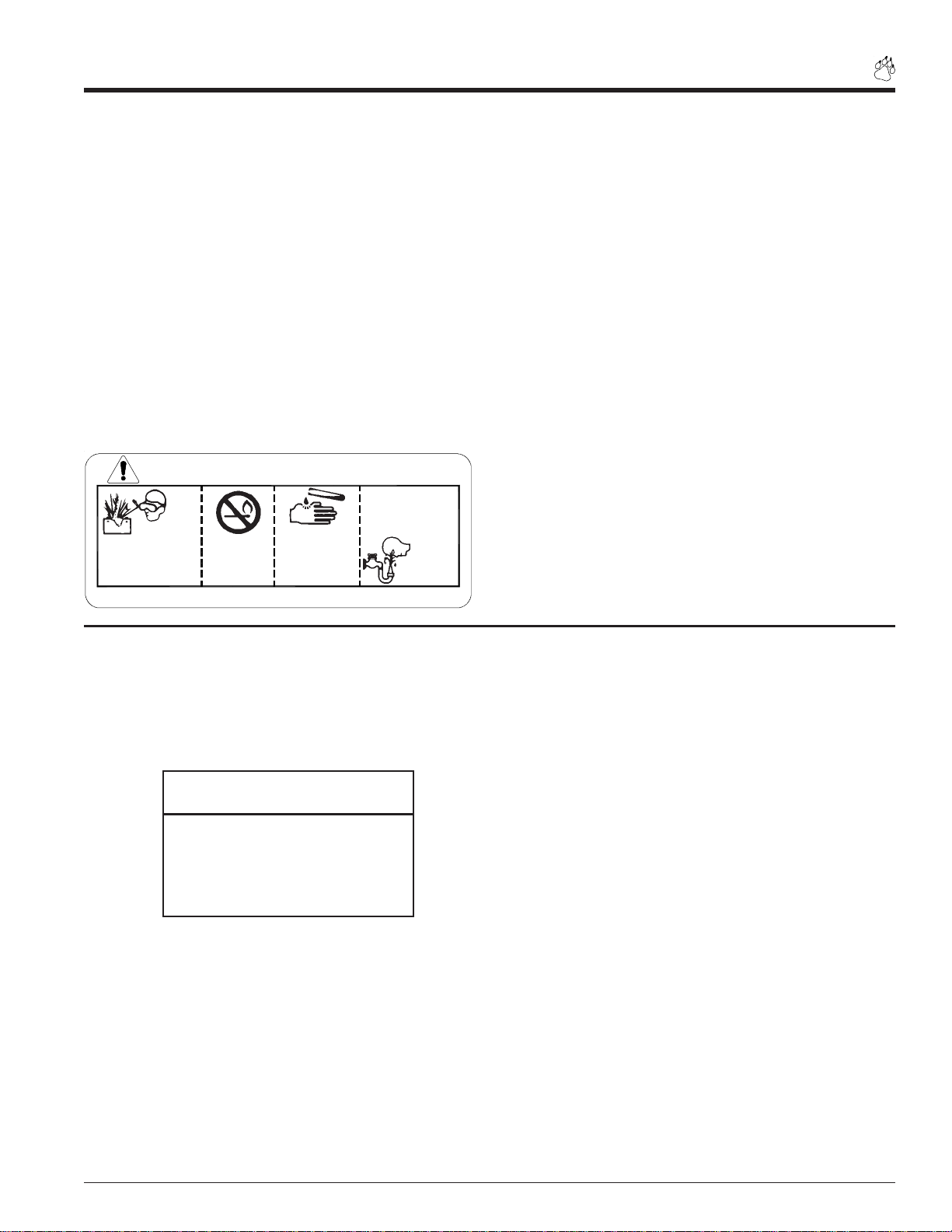
BATTERY SAFETY (MODEL 70385 & 70085)
1. Improper use and care of the battery on electric start
models can result in serious personal injury or property
damage. Always observe the following safety precautions:
• Poison/Danger - Causes Severe Burns. The battery contains sulfuric acid. Avoid contact with skin, eyes or clothing. Keep out of reach of children.
ANTIDOTE-Eye Contact: Flush with water for 15 minutes. Get prompt medical attention.
• The battery produces explosive gases. Keep sparks,
flame or cigarettes away. Ventilate area when charging
battery. Always wear safety goggles when working near
battery.
Safety
ANTIDOTE-External Contact: Flush immediately with lots
of water.
ANTIDOTE-Internal: Drink large quantities of water or
milk. Follow with milk of magnesia, beaten egg or vegetable oil. Call a physician immediately.
DANGER / POISON
FLUSH EYES
IMMEDIATELY
SHIEL D EYES
EXPLOSIVE GASES
CAN CAUSE
BLINDNESS OR
INJURY
KEEP OUT O F THE REACH OF CHI LDREN. DO NO T TIP. KEEP VEN T CAPS TIGHT AN D LEVEL.
NO
• SPARKS
• FLAMES
• SMOKING
SULFURIC
ACID
CAN CAUSE
BLINDNESS OR
SEVERE BURNS
MAINTENANCE AND STORAGE SAFETY
1. Shut off machine and disconnect the spark plug wire when
this equipment is stopped for service, inspection, storage, or to change an accessory. Disconnect battery.
WITH WATER
GET
MEDICAL
HELP
FAST
• The battery contains toxic materials. Do not damage
battery case. With a broken or damaged case, avoid
contact with battery contents. Neutralize acid spills with
a baking soda and water solution. Properly dispose of a
damaged or worn-out battery. Check with local authorities for proper disposal methods.
• Do not short circuit battery. Severe fumes and fire can
result.
• Before working with electrical wires or components: disconnect battery ground (negative) cable first. Disconnect positive cable second. Reverse this order when reconnecting battery cables.
3. Store the machine out of reach of children and where fuel
vapors will not reach an open flame or spark. Drain the
fuel and dispose of it in a safe manner for storage periods
of three months or more.
NOTE
See engine owners manual or contact the engine manufacturer for
engine safety instructions and decals.
2. Replace any missing or unreadable safety decals. Refer
to the parts manual for part numbers when ordering safety
decals from an area Bear Cat dealer.
4. Allow machine to cool before storing in an enclosure.
5. Never store this machine with fuel in the fuel tank inside
a building where fumes may reach an open flame or spark,
or where ignition sources are present such as hot water
and space heaters, furnaces, clothes dryers, stoves, electric motors etc.
Page 5Bear Cat Chipper Shredder Operator’s Manual
Page 12
Safety
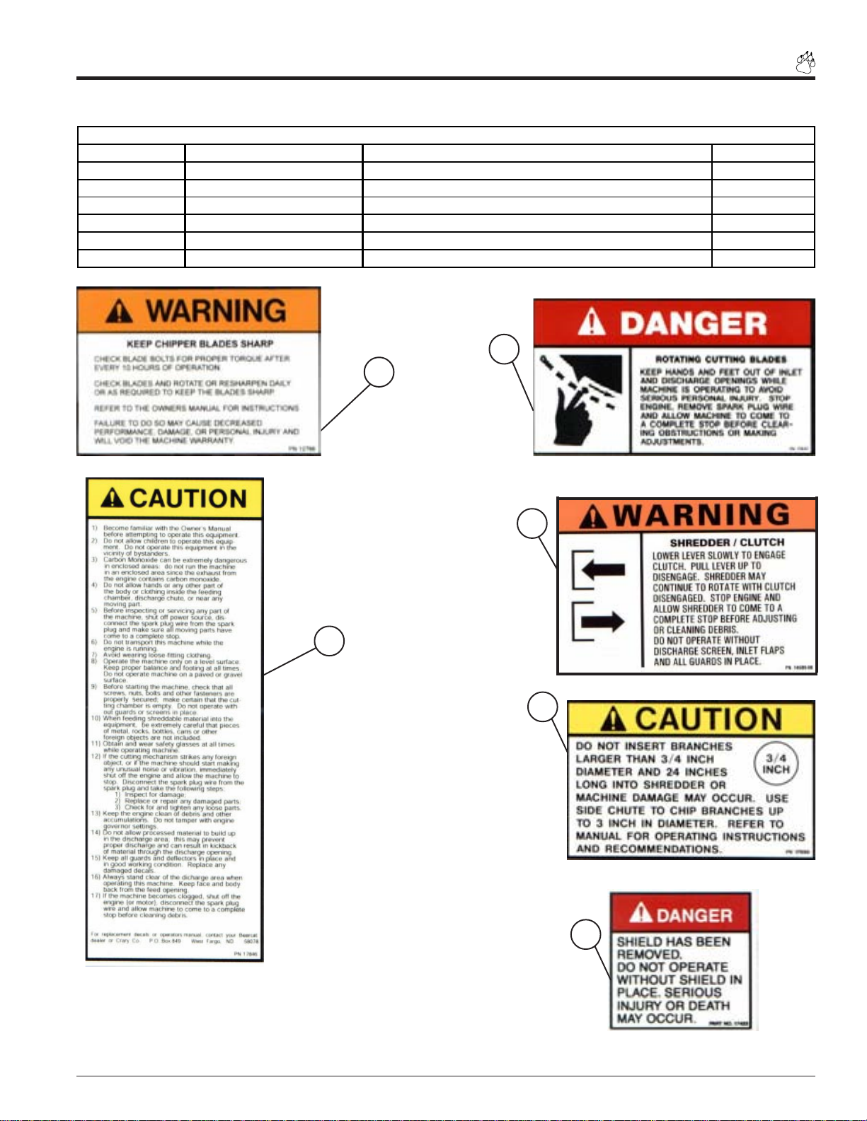
SAFETY DECAL LOCATIONS (MODEL 70050)
Familiarize yourself with all of the safety and operational decals on the machine and the associated hazards. Make certain
that all safety decals and operational decals on this equipment are kept clean and in good condition. The decals are shown
below at reduced sizes. If you need a replacement decal, please refer to the parts catalog. Decals that need replacement
must be applied to their original locations.
2
6
2
1
2
3
4
6
2
5
Fig. #9 70050 decal locations .
Page 6 Bear Cat Chipper Shredder Operator’s Manual
Page 13

SAFETY DECALS
DESCRIPTION AND PART NUMBER
ITEM PART NUMBER DESCRIPTION QTY
1
2 17837 DECAL, BLADE DANGER 4
3 17846 DECAL, OPERATING INSTRUCTIONS 1
4 14699 DECAL, SHREDDER/CLUTCH 1
5 17999 DECAL, SHREDDER SIZE 1
6 17423 DECAL, SHIELD DANGER 2
12766
DECAL, KEEP BLADES SHARP 1
2
1
Safety
4
3
5
6
Page 7Bear Cat Chipper Shredder Operator’s Manual
Page 14
Safety
SAFETY DECAL LOCATIONS (MODEL 70080, 70085, 70180, 70380, 70385)
Familiarize yourself with all of the safety and operational decals on the machine and the associated hazards. Make certain
that all safety decals and operational decals on this equipment are kept clean and in good condition. The decals are shown
below at reduced sizes. If you need a replacement decal, please refer to the parts catalog. Decals that need replacement
must be applied to their original locations.
2
2
1
3
4
2
5
6
Fig. #10, 70080-70385 decal locations.
2
Page 8 Bear Cat Chipper Shredder Operator’s Manual
Page 15
SAFETY DECAL
DESCRIPTION AND PART NUMBER
ITEM PART NUMBER DESCRIPTION QTY
1
2 17837 DECAL, BLADE DANGER 4
3 17846 DECAL, OPERATING INSTRUCTIONS 1
4 14699 DECAL, SHREDDER/CLUTCH 1
5 17999 DECAL, SHREDDER SIZE 1
6 17423 DECAL, SHIELD DANGER 2
12766
DECAL, KEEP BLADES SHARP 1
2
1
Safety
4
3
5
6
Page 9Bear Cat Chipper Shredder Operator’s Manual
Page 16
Safety
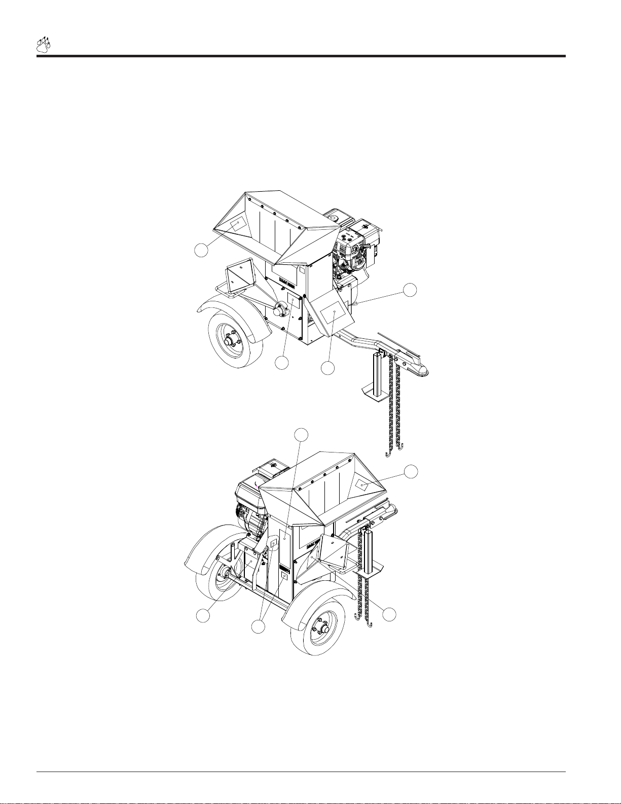
SAFETY DECAL LOCATIONS (MODEL 70580)
Familiarize yourself with all of the safety and operational decals on the machine and the associated hazards. Make certain
that all safety decals and operational decals on this equipment are kept clean and in good condition. The decals are shown
below at reduced sizes. If you need a replacement decal, please refer to the parts catalog. Decals that need replacement
must be applied to their original locations.
2
2
1
4
6
2
3
5
2
Fig. #8, 70580 decal locations.
Page 10 Bear Cat Chipper Shredder Operator’s Manual
Page 17

SAFETY DECAL
DESCRIPTION AND PART NUMBER
ITEM PART NUMBER DESCRIPTION QTY
1
2 17837 DECAL, BLADE DANGER 4
3 17846 DECAL, OPERATING INSTRUCTIONS 1
4 14699 DECAL, SHREDDER/CLUTCH 1
5 17999 DECAL, SHREDDER SIZE 1
6 17423 DECAL, SHIELD DANGER 2
12766
DECAL, KEEP BLADES SHARP 1
2
1
Safety
4
3
5
6
Page 11Bear Cat Chipper Shredder Operator’s Manual
Page 18

Safety
SAFETY DECAL LOCATIONS (MODEL 70050S)
Familiarize yourself with all of the safety and operational decals on the machine and the associated hazards. Make certain
that all safety decals and operational decals on this equipment are kept clean and in good condition. The decals are shown
below at reduced sizes. If you need a replacement decal, please refer to the parts catalog. Decals that need replacement
must be applied to their original locations.
3
3
4
5
1
2
7
3
4
6
2
Fig. #12, 70050S decal locations .
Page 12 Bear Cat Chipper Shredder Operator’s Manual
Page 19

Safety
SAFETY DECALS
EUROPEAN SAFETY DECAL (70050S)
ITEM PART NUMBER DESCRIPTION QTY
1 12172 DECAL, PROTECTION 1
2 12174 DECAL, SHIELD DANGER 2
3 12175 DECAL, INLET AND DISCHARGE 3
4 12176 DECAL, SHREDDER SIZE 1
5 12766 DECAL, KEEP BLADES SHARP 1
6 14703-00 DECAL, CLUTCH ENGAGEMENT 1
7 17837 DECAL, BLADE DANGER 1
1
2
3
4
5
Page 13Bear Cat Chipper Shredder Operator’s Manual
Page 20

Safety
SAFETY DECAL LOCATIONS (MODEL 70080S, 70180S, 70380S)
Familiarize yourself with all of the safety and operational decals on the machine and the associated hazards. Make certain
that all safety decals and operational decals on this equipment are kept clean and in good condition. The decals are shown
below at reduced sizes. If you need a replacement decal, please refer to the parts catalog. Decals that need replacement
must be applied to their original locations.
2
3
8
6
5
1
7
3
4
2
Fig. #13, 70080S-70380S decal locations.
Page 14 Bear Cat Chipper Shredder Operator’s Manual
Page 21

Safety
SAFETY DECALS
EUROPEAN SAFETY DECAL (70080S , 70180S, 70380S)
ITEM PART NUMBER DESCRIPTION QTY
1 12172 DECAL, P ROTECTION 1
2 12174 DECAL, S HIELD DANGER 2
3 12175 DECAL, INLET AND DISCHARGE 3
4 12176 DECAL, S HREDDER SIZE 1
5 12766 DECAL, KEEP BLADES SHARP 1
6 14703-00 DECAL, CLUTCH ENGAGEMENT 1
7 17837 DECAL, B LADE DANGER 1
1
2
3
4
5
Page 15Bear Cat Chipper Shredder Operator’s Manual
Page 22

Safety
SAFETY DECAL LOCATIONS (MODEL 70580S)
Familiarize yourself with all of the safety and operational decals on the machine and the associated hazards. Make certain
that all safety decals and operational decals on this equipment are kept clean and in good condition. The decals are shown
below at reduced sizes. If you need a replacement decal, please refer to the parts catalog. Decals that need replacement
must be applied to their original locations.
2
3
8
3
5
6
7
2
4
1
Fig. #14, 70580S decal locations.
Page 16 Bear Cat Chipper Shredder Operator’s Manual
Page 23

Safety
SAFETY DECALS
EUROPEAN SAFETY DECAL (70580S)
ITEM PART NUMBER DESCRIPTION QTY
1 12172 DECAL, P ROTECTION 1
2 12174 DECAL, S HIELD DANGER 2
3 12175 DECAL, INLET AND DISCHARGE 3
4 12176 DECAL, S HREDDER SIZE 1
5 12766 DECAL, KEEP BLADES SHARP 1
6 14703-00 DECAL, CLUTCH ENGAGEMENT 1
7 17837 DECAL, B LADE DANGER 1
1
2
3
4
5
Page 17Bear Cat Chipper Shredder Operator’s Manual
Page 24

2
Assembly
Section
Your chipper/shredder may arrive totally or partially assembled. If your machine arrives partially assembled, you may need
to perform the steps in this section.
ASSEMBLY INSTRUCTIONS (ALL MODELS EXCEPT MODEL 70580 & 70580S)
STEP # 1: INSTALLING THE HANDLE
WARNING
To prevent personal injury or property damage: Shut off
engine, disconnect spark plug wire, remove ignition key
and make sure that all moving parts have come to a
complete stop, before servicing, adjusting or repairing.
Tools Needed:
ITEM PART NUMBER DESCRIPTION QTY
A 15003 BOLT, 5/16" X 3/4" HEX HEAD 4
(2) 1/2" Open end wrench
or adjustable wrench
(1) 13/16 Socket and
ratchet
B 15250 WASHER, 5/1 6" FLAT 4
C 15356 N UT, 5/16" N YL OCK 4
D 71717 HANDLE, REN TAL HOPPER 1
E
1. Remove the chipper/shredder and hopper assembly from
the shipping box and pallet.
2. Install the hopper handle to the hopper assembly using
(4) 5/16” X 3/4” bolts, (4) 5/16” nylock nuts and (4) 5/16”
flat washers as shown below. (The hopper handle is not
used on model 70580 & 70580S).
PART S LIST
71788 ASSEMBLY, NARROW HOPPER (M ODEL 70050 ONLY) 1
70982 ASSEMBLY, WIDE HOPPER (ALL OTHER MODELS) 1
D
E
C
A
B
Fig. #15
ABC
(Parts not shown actual size)
ITEM PART NUMBER DESCRIPTI ON QTY
A 15003 BOLT, 5/16" X 3/4 " HEX HEAD 4
B 15250 WA SHER, 5/ 16" FL AT 4
C 15356 NUT , 5/16" N YLOCK 4
D 71718 HANDLE, RENTAL HOPPER 1
71769 ASSEMBLY, NAR ROW EUROPEAN HOPPER (MOD EL 70050S ONLY) 1
E
71775 ASSEMBLY, WID E EUROPEAN HOPPER (ALL OTHER MODELS) 1
EUROPEAN HANDLE INSTALL
E
A
Fig. #16
Page 18 Bear Cat Chipper Shredder Operator’s Manual
D
C
B
Page 25

ASSEMBLY INSTRUCTIONS (ALL MODELS)
Assembly
WARNING
To prevent personal injury or property damage: Shut off
engine, disconnect spark plug wire, remove ignition key
and make sure that all moving parts have come to a
complete stop, before servicing, adjusting or repairing.
STEP # 2: INSTALLING THE HOPPER
3. Assemble the hopper assembly to the frame so the handle
is located above the engine and the opening is toward
the chipper chute.
4. Install (Qty. 12) 5/16” X 3/4” bolts so the head of the bolt
is inside the hopper. Fasten bolts with the provided (Qty.
12) 5/16” flat washers and (Qty. 12) 5/16” nylock nuts.
5. Inspect the entire machine to insure all bolts, nuts, and
screws are tight. Refer to the torque chart for correct
settings. Read and understand all decals and instructions.
IMPORTANT
If any bolts or nuts are dropped in the shredder be sure to
remove them before starting the machine. Remove items
from the shredder area by removing the discharge screen.
HARDWARE
HGF
(Parts not shown actual size)
G
F
H
ITEM PART NUMBER DESCRIPTION QTY
J 15010 BOLT, 3/8" X 3-1/2" GR5 HHCS ZP 2
K 15031 WASHER, 3/8" FLAT ZP 2
L 15388 NUT, 3/8" NE NYLOCK ZP 2
M 16008 TIRE AND WHEEL ASSEMBLY 4.80 - 8 2
N 16264 BOLT, WHEEL .500-20 UNF X 1.437 8
O 17879 PIN, SNAP 3/8" X 1-1/8" USABLE LGH 1
P 70372 WELDMENT, HITCH JACK 1
Q NPN HITCH POLE 1
PARTS LIST
Figure #17
I
I
G
F
H
ITEM PART NUMBER DESCRIPTION QTY
F 15003 BOLT, 5/16" X 3/4" HEX HEAD 12
G 15250 WASHER, 5/16" FLAT 12
H 15356 NUT, 5/16" NYLOCK 12
I NPN EUROPEAN HOPPER W/HANDLE 1
EUROPEAN HOPPER INSTALLATION
Figure. # 18
Page 19Bear Cat Chipper Shredder Operator’s Manual
Page 26

Assembly
(
)
ASSEMBLY INSTRUCTIONS (ALL “S” MODELS)
WARNING
To prevent personal injury or property damage: Shut
off engine, disconnect spark plug wire, remove ignition
key and make sure that all moving parts have come to
a complete stop, before servicing, adjusting or repairing.
STEP # 3: INSTALLING THE CHIPPER
CHUTE EXTENSION
6. Place the chipper chute extension onto the chute. Line up
the four holes located on the bottom of the extension and
the top of the chute.
7. Place a 5/16” X 3/4” bolt into each hole. Secure bolt by
screwing on a 5/16” nut. Tighten nut until snug against
the chute extension.
IMPORTANT
If any bolts or nuts are dropped in the shredder be sure to
remove them before starting the machine. Remove items
from the shredder area by removing the discharge screen.
ITEM PART NUMBER DESCRIPTION QTY
CHIPPER CHUTE EXTENSION ASSEMBLY
1 12175 DECAL, INLET AND DISCHARGE 1
2 14199-00 DECAL, CHIPPER SIZE 1
3 70684-35 WELDMENT, CHUTE EXTENSION 1
MISCELLANEOUS CHIPPER CHUTE EXTENSION PARTS
ITEM PART NUMBER DESCRIPTION QTY
4 15003 BOLT, 5/16" X 3/4" GR5 HEX 4
5 15356 NUT, 5/16" NE NYLOCK ZP 4
71771
3
1
2
4
5
Figure #19 Chipper Chute Extension
Page 20 Bear Cat Chipper Shredder Operator’s Manual
Page 27

ASSEMBLY INSTRUCTIONS (ALL “S” MODELS)
)
)
)
)
Assembly
WARNING
To prevent personal injury or property damage: Shut off
engine, disconnect spark plug wire, remove ignition key
and make sure that all moving parts have come to a
complete stop, before servicing, adjusting or repairing.
STEP # 4: INSTALLING THE WIDE AND
NARROW DISCHARGE ASSEMBLY
8. Place the respective discharge weldment onto the chip per. The holes on the weldment should line up with holes
on the chipper as shown in Figures #20 and #21.
9. Place the 5/16” X 7 1/2” (Narrow) or the 5/16” X 10”
(Wide) bolt through the corresponding holes that attach
the top of the weldment to the chipper. Secure with a
5/16” nut tighten to the proper torque.
10.To secure the bottom of the weldment to the chipper,
place a 5/16” X 3/4” bolt into each hole. Secure with a
5/16” nut tighten to the proper torque.
IMPORTANT
If any bolts or nuts are dropped in the shredder be sure to
remove them before starting the machine. Remove items
from the shredder area by removing the discharge screen.
ITEM PART NUMBER DESCRIPTION QTY
1 12175 DECAL, INLET AND DISCHARGE 1
2 71389 WELDMENT, NARROW EUROPEAN DISCHARGE 1
ITEM PART NUMBER DESCRIPTION QTY
3 15003 BO LT, 5/16" X 3/4" GR5 HEX CAPSCR EW ZP (LOCATED IN OWNERS KIT)2
4 15356 N UT, 5/16" NE NYLOCK ZP (LOCATED IN OWNERS KIT
5 15407 BO LT, 5/16" X 7-1 /2" HHCS NC GR 5 ZP (LOCATED IN OWNERS KIT
ITEM PART NUMBER DESCRIPTION QTY
1 12175 DECAL, INLET AND DISCHARGE 1
2 71386 WELDMENT, WIDE EURO DISCHARGE 1
ITEM PART NUMBER DESCRIPTION QTY
3 15003 BOLT, 5/16" X 3/4" G R5 HEX CAPSCREW ZP (LOCATED IN OWNERS KIT)2
4 15356 NUT, 5 /16" NE NYLOC K ZP (LOCATED IN OWNERS KIT
5 15408 BOLT, 5/16" X 10 " HHCS NC GR5 ZP (LOCATED IN OWNERS KIT
NARROW EUROPEAN DISCHARGE ASSEMBLY (71773)
MISCELLANEOUS NARROW EUROPEAN DISCHARGE ASSEMBLY PARTS
WIDE EUROPEAN DISCHARGE ASSEMBLY (71776)
MISCELLANEOUS WIDE EUROPEAN DISCHARGE ASSEMBLY PARTS
3
1
3
1
3
4
5
Figure # 20 Wide Discharge Assembly
4
1
4
2
3
5
4
2
1
Figure # 21 Narrow Discharge Assembly
Page 21Bear Cat Chipper Shredder Operator’s Manual
Page 28

Assembly
ASSEMBLY INSTRUCTIONS (MODEL 70580 & 70580S ONLY)
10. Install hitch pole assembly to chipper shredder frame
and secure using (2) 3/8” X 2-1/2” bolts, (2) 3/8” flat
WARNING
washers and (2) 3/8” nylock nuts.
To prevent personal injury or property damage: Shut off
engine, disconnect spark plug wire, remove ignition key
and make sure that all moving parts have come to a
complete stop, before servicing, adjusting or repairing.
STEP # 5: INSTALLING THE WHEELS,
JACK AND HITCH
6. Hold one wheel to a hub and align the wheel lug holes
with the hub lug holes.
7. Thread the wheel bolts into the holes and tighten to the
proper torque. Follow an alternating cross pattern when
tightening wheel bolts.
8. Repeat for the remaining wheel.
9. Install hitch jack onto hitch pole and install snap pin.
HARDWARE
(Parts not shown actual size)
ITEM PART NUMBER DESCRIPTION QTY
J 15010 BOLT, 3/8" X 3-1/2" G R5 HHCS ZP 2
K 15031 W ASHER, 3/8" FLAT ZP 2
L 15388 NUT, 3/8" NE NY LOCK ZP 2
M 16008 TIRE AND W HEEL ASSEMBLY 4.80 - 8 2
N 16264 BOLT, WH EEL .500-20 UNF X 1.437 8
O 17879 PIN, SNA P 3/8" X 1-1/8" USABLE LGH 1
P 70372 W ELDMENT, HITCH JACK 1
Q NPN HITCH P OLE 1
PARTS LIST
L
M
K
Q
J
N
O
P
M
N
Fig. #22
Page 22 Bear Cat Chipper Shredder Operator’s Manual
L
K
Q
J
O
P
Fig. #23
Page 29

ADDING MOTOR OIL TO ENGINE (ALL MODELS)
IMPORTANT
Motor oil must be
added to the engine
before it is started.
1. The machine was shipped without
oil in the engine. Fill the engine
crankcase with the amount of oil
specified in the engine owners
manual.
INSTALL THE BATTERY (MODELS 70385 & 70085)
1. The machine may or may not have been shipped with a
battery depending on your area. If you did not receive a
battery with your machine, you will need to purchase
one.
To avoid sparks and a possible explosion or fire due to a
Use a battery that meets or exceeds the following specifications:
Battery Category, Lawn and Garden
BCI Group Size U1
200-250 CCA
7-3/4” X 5-3/16” X 7-5/16”
Suggested Source:
Exide Cutting Edge, Type GT-H
short circuit:
• Do not touch the positive (+) battery terminal and any
surrounding metal with tools, jewelry or other metal objects.
• When installing battery cables, connect positive (+)
cable first and negative (-) cable last.
5. Place charged battery in battery box on chipper shredder.
Assembly
Fig. #25 Honda oil fillFig. #24 Briggs oil fill
WARNING
NOTE
The battery that was shipped with your machine was shipped dry. Service the battery
before installation.
If you received a battery with your machine, proceed to the
next step.
2. Remove or destroy any sealing device which may have
been used to close or restrict the vent openings.
3. Remove battery vent caps and fill cells until baffle plate
is covered with 1.25” of electrolyte at 80° F. Battery and
electrolyte must be at a temperature above 60° F, but
preferably not above 100° F.
4. After filling, charge the battery and put into service immediately.
Charging Times:
Temperature over 60° F
3 amperes for 4 Hours.
6. Remove key from engine ignition.
7. Install the positive (+) battery cable to the positive (+)
battery terminal using a 5/16 X 1” hex head bolt and 5/
16 nylock nut. An insulating boot is loosely installed
on this cable. Slide the insulating boot over the terminal, making sure to cover the terminal completely.
8. Install the negative (-) cable on the negative (-) battery
terminal using a 5/16 X 1” hex head bolt and 5/16
nylock nut. No insulating boot exists for this terminal.
9. Secure battery box with bolt and clamp.
IMPORTANT
DO NOT ATTEMPT TO START THE ENGINE AT THIS
TIME. Wait until you have read the complete starting
instructions in the Operation Section of this Manual.
Temperature under 60° F
3 amperes for 6 Hours.
Page 23Bear Cat Chipper Shredder Operator’s Manual
Page 30

3
Features & Controls
Section
FEATURES AND CONTROLS IDENTIFICATION
Learn the location of the features and controls on your machine before operating.
MODEL # 70050, 70080, 70085, 70180, 70380, 70385
TRANSPORT
HANDLE
SHREDDER
HOPPER
ENGINE
SHREDDER
KNIVES
CHIPPER BLADE
ROTOR ASSEMBLY
DISCHARGE
COVER
SHREDDER
HOPPER
DEFLECTOR
CHIPPER
CHUTE
CLUTCH
ENGAGEMENT
ARM
DISCHARGE
DEFLECTOR
MODEL # 70050S, 70080S, 70180S, 70380S
SHREDDER
HOPPER
CLUTCH
NGAGEMENT
ARM
CHIPPER
BLADE
ROTOR
ASSEMBLY
DISCHARGE
COVER
TRANSPORT
HANDLE
SHREDDER
KNIVES
DISCHARGE
DEFLECTOR
SHREDDER
HOPPER
DEFLECTOR
ENGINE
TRANSPORT
HANDLE
Fig #26 70050-70385 features and controls.
Fig #27, 70050S-70380S features and controls.
CHIPPER CHUTE
EXTENSION
DESCRIPTION OF OPERATION
Understanding how your machine works will help you achieve the best results when using your Chipper Shredder. The
following descriptions define the operation of your machine.
CHIPPING OPERATION
The chipping operation takes place on the front side of the machine, where hardened steel chipper blades are mounted on
a rotating rotor assembly. Material fed into the chipper chute is sliced into small chips and propelled out through a
discharge screen. The chips can be diverted into a container or onto the ground.
SHREDDING OPERATION
In this operation hardened steel shredder knives grind up material fed into the shredder chute. The shredded material then
leaves the shredder area by traveling through the discharge screen. The shredded material can be diverted into a container
or onto the ground.
Page 24 Bear Cat Chipper Shredder Operator’s Manual
Page 31

Features & Controls
USE OF CONTROLS
Model # 70050, 70080, 70085,
70180, 70380, 70385, 70050S,
70080S, 70180S, 70380S.
1. Engine Throttle: Changes engine
speed. Push lever to fast for starting and operating. Push lever to
slow for idle and warm-up. Push
throttle lever to 1/2 throttle to shut
engine off. Refer to engine manual
for further engine operating instructions.
2. Engine Choke: Use when starting cold engine. Move lever to
choke position when starting.
Move lever to run position when
engine is running. Refer to engine
manual for further engine operating instructions
3. Clutch Lever: During engine startup, clutch must be in the disengaged
position (see Fig #30). With engine at
half throttle, carefully engage the rotor
by slowly pushing the clutch down, allowing the rotor to speed up gradually.
Engaging the clutch too quickly with
the engine at full or half throttle will
bog down the engine and will shorten
the life of the belt. To disengage the
rotor, first idle the engine down, then
lift the clutch up.
4. Key Switch: The key switch is
used to start or kill the engine.
Refer to the engine manual for further operating instructions.
Fig. #32 Honda on/off switch
Fig. #28 Briggs throttle and choke
Fig. #29 Honda throttle and control
locations
Fig #30 Disengaged Clutch
Fig # 31 Engaged Clutch
WARNING
To prevent personal injury or property damage: Shut off engine, disconnect spark plug wire, remove ignition key and make sure that all
moving parts have come to a complete stop, before servicing, adjusting or repairing.
Fig. #33 Honda electric key switch
Fig. #34 Briggs electric on/off switch
5. Shredder Chute: Materials to be
shredded are fed through the shredder chute to the shredder knives.
6. Chipper Chute: Materials to be
chipped are fed through the chipper chute to the chipper blades.
7. Chipper Blades: The chipper
blades chip material that is fed into
the chipper chute.
8. Shredder Knives: The shredder
knives shred material that is fed
into the shredder chute.
Page 25Bear Cat Chipper Shredder Operator’s Manual
Page 32

Features & Controls
FEATURES AND CONTROLS IDENTIFICATION
Learn the location of the features and controls on your machine before operating.
ASSEMBLY
CLUTCH
ENGAGEMENT
ARM
SHREDDER
HOPPER
ROTOR
MODEL # 70580
CHIPPER
BLADE
DISCHARGE
SCREEN
ENGINE
SHREDDER
KNIVES
DISCHARGE
DEFLECTOR
SHREDDER
HOPPER
DEFLECTOR
HITCH
COUPLER
CHIPPER
CHUTE
JACKSTAND
SAFETY
CHAINS
SHREDDER
HOPPER
ROTOR
ASSEMBLY
CLUTCH
ENGAGEMENT
MODEL # 70580S
ARM
CHIPPER
BLADE
SHREDDER
DEFLECTOR
HOPPER
DISCHARGE
SCREEN
ENGINE
SHREDDER
KNIVES
DISCHARGE
DEFLECTOR
CHIPPER
CHUTE
EXTENSION
Fig. #35 70580 features and controls
WHEEL & TIRE
ASSEMBLY
WHEEL & TIRE
ASSEMBLY
Fig. #36, 70580S features and controls
JACKSTAND
DESCRIPTION OF OPERATION
Understanding how your machine works will help you achieve the best results when using your Chipper Shredder. The
following descriptions define the operation of your machine.
CHIPPING OPERATION
The chipping operation takes place on the right side of the machine, where hardened steel chipper blades are mounted on
a rotating rotor assembly. Material fed into the chipper chute is sliced into small chips and propelled out through a
discharge screen. The chips can be diverted into a container or onto the ground.
SHREDDING OPERATION
In this operation hardened steel shredder knives grind up material fed into the shredder chute. The shredded material then
leaves the shredder area by traveling through the discharge screen. The shredded material can be diverted into a container
or onto the ground.
Page 26 Bear Cat Chipper Shredder Operator’s Manual
Page 33

USE OF CONTROLS
Model # 70580 & 70580S.
WARNING
To prevent personal injury or property damage: Shut
off engine, disconnect spark plug wire and make sure
that all moving parts have come to a complete stop
before, servicing, adjusting or repairing.
1. Engine Throttle: Changes engine speed. Push lever
to fast for starting and operating. Push lever to slow for
idle and warm-up. Push throttle lever to 1/2 throttle to
shut engine off. Refer to engine manual for further engine operating instructions.
2. Engine Choke: Use when starting cold engine. Move
lever to choke position when starting. Move lever to run
position when engine is running. Refer to engine manual
for further engine operating instructions.
Features & Controls
Fig. # 39 Engaged Clutch
4. Key Switch: The key switch allows the engine to be
turned on or off. Refer to engine manual for further engine operating instructions.
Fig. #37 Throttle and Choke Locations
3. Clutch Lever: During engine start-up, clutch must be
in the disengaged position (see Fig #38). With engine
at half throttle, carefully engage the rotor by slowly pushing the clutch down, allowing the rotor to speed up gradually. Engaging the clutch too quickly with the engine at
full or half throttle will bog down the engine and will
shorten the life of the belt. To disengage the rotor, first
idle the engine down, then lift the clutch up.
Fig #38 Disengaged Clutch
Fig. #40 On/Off Switch
5. Shredder Chute: Materials to be shredded are fed
through the shredder chute to the shredder knives.
6. Chipper Chute: Materials to be chipped are fed through
the chipper chute to the chipper blades.
7. Jack Stand: Always have the jack stand retracted from
the ground when moving the unit. When in use, be sure
the jack stand is down and locked in position with the
snap pin.
8. Safety Switch: This machine is equipped with a en-
gine kill safety switch which prevents the engine from
starting unless the knife access cover is closed.
9. Chipper Blades: The chipper blades chip material that
is fed into the chipper chute.
10. Shredder Knives: The shredder knives shred material
that is fed into the shredder chute.
Page 27Bear Cat Chipper Shredder Operator’s Manual
Page 34

4
Operation
Section
WARNING
Before operating your machine, be
sure you read and understand all
safety, controls and operating instructions in this Owner/Operators
manual and on your machine.
Read this section thoroughly before you start the engine. The instructions given
here will help you become familiar with your machine and have you operating
efficiently in a short time.
This Section explains how to:
• Fill the tank
• Start Electric models
Failure to follow these instructions
can result in serious injury or property damage.
As with any other piece of outdoor
power equipment, getting the “feel” for
how your machine operates and getting
to know the best techniques for
particular jobs are important to overall
good performance.
FILLING THE TANK
DANGER
Gasoline is highly flammable
and its vapors are explosive. To
prevent personal injury or property damage:
Store gasoline only in approved
containers, in well ventilated, unoccupied buildings, away from sparks
or flames. Do not fill the fuel tank
while the engine is hot or running,
since spilled fuel could ignite if it
comes in contact with hot parts or
sparks from ignition. Do not start
the engine near spilled fuel. Never
use gasoline as a cleaning agent.
• Start recoil models
• Stop the machine
• Chip
• Shred
• Change the discharge screen
• Clear the machine of a plugged rotor
FILLING THE FUEL TANK
Fuel Type:
For best results use only clean, fresh,
unleaded gasoline with a pump sticker
octane rating of 87 or higher. In countries using the Research method, it
should be 90 octane minimum.
Purchase gasoline in small quantities
and store in clean, approved containers. A container with a capacity of 2
gallons or less with a pouring spout is
recommended. Such a container is
easier to handle and helps eliminate
spillage during refueling. DO NOT MIX
OIL WITH GASOLINE.
Gasoline Alcohol blends
Gasohol (up to 10% ethyl alcohol, 90%
unleaded gasoline by volume) is approved as a fuel for Briggs and Honda
engines. Other gasoline/alcohol blends
are not approved.
Gasoline Ether blends
Methyl Tertiary Butyl Ether (MTBE) and
unleaded gasoline blends (up to a maximum of 15% MTBE by volume) are
approved as a fuel for Briggs and Honda
engines. Other gasoline/ether blends
are not approved.
To Add Gasoline.
1. Stop engine, wait for all parts to stop
moving, and disconnect spark plug
wire. Remove Key/Tool from key
switch. Allow the engine and muffler to cool for at least three minutes.
2. Clean area around fuel fill cap and
remove cap.
3. Using a clean funnel, fill fuel tank to
1/2” below bottom of filler neck to
provide space for any fuel expansion. Install fuel fill cap securely and
wipe up any spilled gasoline.
Page 28 Bear Cat Chipper Shredder Operator’s Manual
Page 35

STARTING ELECTRIC MODELS
Operation
Move machine to a clear, level
area outdoors before starting. Do
not operate in the vicinity of bystanders. Make sure cutting chamber is empty before starting.
1. Check engine oil level before starting.
2. Place the throttle control midway
between the “slow” and “fast” positions. Place the choke control into
the “on” position.
3. Start the engine by activating the
key switch. Release the switch as
soon as the engine starts.
4. Move throttle to full position.
5. Slowly engage the hand lever to start
the chipper shredder.
NOTE
Do not crank the engine continuously for more than 10 seconds at
a time. If the engine does not start,
allow a 60 second cool down period
between starting attempts. Failure
to follow these guidelines can burn
out, or permanently damage, the
starter motor.
NOTE
If the engine develops sufficient
speed to disengage the starter but
does not keep running (a false start),
the engine rotation must be allowed
to come to a complete stop before
attempting to restart the engine. If
the starter is engaged while the flywheel is rotating, damage to the
starter may result.
NOTE
If the starter does not turn the engine over, shut off starter immediately. Do not make further attempts
to start the engine until the condition is corrected. Do not jump start
using another battery.
6. For a Cold Engine — Gradually
return the choke control to the “off”
position after the engine starts and
warms up.
The engine/equipment may be
operated during the warm up period,
but it may be necessary to leave the
choke partially on until the engine
warms up.
7. For a Warm Engine — Return choke
to “off” position as soon as engine
starts.
STARTING RECOIL MODELS
Move machine to a clear, level
area outdoors before starting. Do
not operate in the vicinity of bystanders. Make sure cutting chamber is empty before starting.
1. Check engine oil level before starting.
2. Place the throttle control midway
between the “slow” and “fast” positions. Place the choke control into
the “on” position.
3. Turn the key switch to “on” (if
equipped). Pull the recoil starter
until the engine starts. Make sure
the starting cord retracts.
4. Move throttle to full position.
5. Slowly engage the hand lever to start
the chipper shredder.
6. For a Cold Engine — Gradually
return the choke control to the “off”
STOPPING THE CHIPPER/SHREDDER
1. Move the throttle to the “slow” or “low” idle position.
WARNING
Allow the machine to come to complete stop
before inspection or servicing. The rotor is
heavy and has inertia built up that will allow the
rotor continue to turn for some time after the clutch
has been disengaged. You can distinguish when
the rotor has come to a complete stop when there
is no noise, vibration, or by reengaging the clutch
to slow the rotor to a stop.
2. Disengage the clutch engagement arm.
3. Allow the engine to run at idle for 30-60 seconds; then stop the
4. Allow machine to come to a complete stop.
position after the engine starts and
warms up.
The engine/equipment may be operated during the warm up period,
but it may be necessary to leave
the choke partially on until the engine warms up.
7. For a Warm Engine — Return choke
to “off” position as soon as engine
starts.
engine by moving the throttle to the off position or turn off ignition.
Page 29Bear Cat Chipper Shredder Operator’s Manual
Page 36

Operation
CHIPPING GUIDE
The Bear Cat chipper chips a variety of materials into a more readily decomposing or handled
condition. The following guidelines can help you get started.
• Run unit at full operating speed before starting to chip material.
• Select limbs that are up to 3 inches in diameter. Trim side branches that cannot be bent
NOTE
Please read and
follow all safety
instructions in this
manual. Failure
to operate the
chipper in accordance with the
safety instructions
MAY RESULT IN
PERSONAL INJURY!
IMPORTANT
Exclude pieces of
metal, rocks,
bottles, cans, and
other foreign objects when feeding chipable material into the machine.
• Feed brush from the side of the chipper chute, rather than from the front. Then, step aside to
• Do not lean over the chipper chute to push objects into the cutting device. Use a push stick or
• Never use shovels or forks to feed brush. They can be chipped, are expensive to replace, and
• Never feed brush into the chipper chute with your feet.
• Place limb, butt end first, into the chipper chute until it contacts the chipper blades. The actual
• Stop the material feeding and allow the engine to recover if the engine slows to where it may
• Remove the branch and rotate it before reinserting it into the chute if the chipper jams.
• Alternately insert and retract the limb or insert continuously at a rate that will not kill the engine.
• Chipping dead, dry material will create heat and dull the chipping blades quickly.
enough to feed into the chipper chute. Hold small diameter branches together in a bundle and
feed in simultaneously.
avoid being hit by the brush moving into the chipper.
brush paddle.
cause extensive damage. In addition, metal pieces can come back to injure or kill.
feed rate of the limb into the chipper will depend on the type of material fed and sharpness of the
cutting blades.
stall.
• Alternate greener material with dry material to lubricate the chipping blades for longer life and
better performance.
• The chipping blades will become dull and will require periodic sharpening. Refer to Service and
Maintenance, "Sharpening Chipper Blades."
WARNING
Do not leave machine unattended, or attempt any inspection or service unless
the engine is stopped and the key removed from key switch.
SHREDDING GUIDE
1. Place materials to be shredded (grass, leaves, garden refuse, sticks and branches less then
3/4 inch diameter and 24 inches long, etc.) into the hopper. Feed material evenly into the
shredder so that the engine does not lug down or the shredder become plugged. Attempting to
use the clutch to clear a plugged rotor will cause belt damage. Refer to the section, Clearing
Plugged Rotor, for instructions. Branches or items that plug or cause the machine to stall
should be fed in more evenly or put through the chipper chute.
Page 30 Bear Cat Chipper Shredder Operator’s Manual
Page 37

CHANGING THE DISCHARGE SCREEN
Operation
WARNING
To prevent personal injury or property damage: Shut off engine, disconnect spark plug wire, remove ignition key, and make sure that all
moving parts have come to a complete stop, before, servicing, adjusting or repairing.
The most common reason to remove
the discharge screen is for sharpening
the chipper blades. Removal is also
necessary for optional discharge
screens.
A standard coarse (1-1/2 inch diameter hole) discharge screen is supplied
with your machine. Optional discharge
screens may be purchased for your
machine which include:
• Fine (3/8 inch diameter holes)
• Medium (3/4 inch diameter holes)
• Coarse (1-1/2 inch diameter holes
shipped standard)
• Wet Debris screen (1-1/2 inch diameter slots)
To remove change the discharge
screen follow this procedure.
1. Lift discharge door to gain access
to the discharge screen.
2. Using a 1/2” wrench, remove the
5/16” bolt and nut securing the discharge screen to the chipper shredder frame.
3. Pull discharge screen out from the
bottom and rotate the top down.
4. Clean any trash or debris out from
the screen area.
To sharpen or replace the chipper
blades, see the Maintenance section
of this manual.
5. Select replacement screen option
and insert the top of the screen into
the slot in the chipper body and push
the bottom of the screen inward so
bolt holes align.
6. Install the bolt from the underside
upward through the frame and
screen, attach nut and tighten to
specified torque.
DANGER
SHARP KNIVES,
KEEP OUT!
Consult your local Bear Cat Dealer for
optional equipment.
BOLT,
5/16" X 1-3/4"
DISCHARGE
SCREEN
Fig. #41
CLEARING THE MACHINE OF A PLUGGED ROTOR
WARNING
3. Remove shredder screen.
If the machine becomes plugged, shut off the engine, disconnect the spark plug wire and allow the machine to
come to a complete stop before clearing debris. Do not
operate machine without proper guards and screens in
place.
1. Stop engine, disengage rotor clutch and allow machine
to come to a complete stop. Remove the spark plug wire.
2. Loosen and remove the bolt securing the discharge
screen.
4. Clean the debris out of the shredding rotor and or chipper
top discharge area and tube. Turn the rotor by hand to be
sure it is free to rotate.
5. Install shredder screen and retaining bolt.
6. Replace spark plug wire, restart engine and resume operation.
NUT, 5/16"
NYLOCK
Page 31Bear Cat Chipper Shredder Operator’s Manual
Page 38

5
Service & Maintenance
Section
MAINTENANCE SCHEDULE
The following items listed in the service and maintenance
WARNING
To prevent personal injury or property damage: Shut
off engine, disconnect spark plug wire and make sure
that all moving parts have come to a complete stop
before, servicing, adjusting or repairing.
SERVICE AND MAINTENANCE SCHEDULE
COMPONENT
ENGINE OIL CHECK OIL LEVEL
FUEL TANK FILL
AIR CLEANER CHECK AND CLEAN¹
AIR INTAKE CLEAN¹
NUTS AND BOLTS CHECK
PRE-CLEANER
ELEMENT
ENGINE OIL C HANGE¹
COOLING SHROUDS CLEAN¹
SPARK PLUG
STARTER DRIVE SERVICE²
SOLENOID SHIFT
STARTER
FUEL FILTER REPLACE
CHIPPER BLADES
SHREDDER KNIVES CHECK CONDITION OF
BATTERY
CONNECTIONS
B E LT C O ND ITIO N C H E C K
BELT/PULLEY
ALIGNMENT
SAFETY SWITCH CHECK FUNCTION
TIRE PRESSURE CHECK
ENTIRE MACHINE CLEAN
¹ PERFORM MORE FRE QUENTLY UNDER EXTREMELY DUSTY CONDITIONS.
² HAVE A KOHLER ENGINE SERVICE DEALER PERFORM THIS SERVICE.
³ IT IS A GOOD SIGN THAT YOUR CHIPPER BLADES WILL NEED SHARPENING WHEN MATERIAL STOPS SELF FEEDING.
*Grease rotor bearing every 50 hrs of operation.
MAINTENANCE
REQUIRED
CLEAN¹
CHECK CONDITION
AND GAP
DISASSEMBLE AND
CLEAN²
CHECK, SHARPEN IF
NEED ED ³
CHECK
CHECK
BEFOR
E EACH
USE
•
EVERY
HOURS
schedule are to be checked, and if necessary, corrective
action should be taken. Probably the most important maintenance is to keep the chipper blades sharp. This schedule
is designed for units operating under normal conditions. If
the unit is operating in adverse or severe usage conditions it
may be necessary for the items to be checked and serviced
more frequently.
See engine owners manual for further maintenance and
troubleshooting information.
FREQUENCY
EVERY
200
HOURS
8
EVERY
25
HOURS
EVERY
50
HOURS
EVERY
100
HOURS
•
•
•
•
•
EVERY
500
HOURS
•
•
EVERY
1500
HOURS
•
Page 32 Bear Cat Chipper Shredder Operator’s Manual
Page 39

SHARPENING CHIPPER BLADES
The chipper blades will eventually become dull, making chipping difficult and adding extra strain on the machine. Sharpen
the chipper blades every 5-15 hours of chipper operation. To remove the chipping blades for sharpening, follow
the procedure below:
Removing The Blades:
WARNING
To prevent personal injury or property damage: Shut off
engine, disconnect spark plug wire, remove ignition key
(if applicable), disconnect the driveline from the source
providing power and make sure that all moving parts have
come to a complete stop, before servicing, adjusting or
repairing.
The chipping blades are sharp! Use care when working
on machine to avoid injury.
Service & Maintenance
2. Be sure to use short grinding times and cool with water
between grinding.
3. Try to remove an equal amount off each blade to maintain
balance.
NOTE
Never sharpen or grind on the back side of the chipper
blade. This will cause the edge to roll and damage will
occur to the chipping blade, causing poor chipping and
feeding of material. Small imperfections, nicks, burrs, etc.
on the flat side of the blade will not affect performance of
the machine.
4. The maximum that can be ground off the blades is .30
inches, after this the blades must be replaced. For refer
ence, new blades are 2”.
Reinstalling the blades:
1. Place a blade back on the rotor and attach with 5/16”
bolt. Repeat for the second blade.
1. Flip the discharge cover up.
2. Remove the 5/16” bolt and nylock nut holding the shredder screen.
3. Disconnect and remove the shredder screen from the
machine.
4. Remove the two 5/16” hex head bolts holding the chipper
blade itself. Repeat for the second blade.
5. Inspect blades to see if cracks or nicks are visible. If
cracks are present, replace the blades. If nicks can not
be removed by sharpening blade, replace the blade.
Sharpening the Blades:
1. When sharpening the blades grind the angled edge of the
chipping blade to 45 degrees. This is best accomplished
on a slow-speed wet grinder. If you use a bench grinder
be careful when grinding so that the blade material does
not get too hot and change color–this will remove the
blade's special heat treated properties.
MOUNTING
SHARPENED
SURFACE
MOUNTING
SURFACE
DO NOT GRIND
Fig. #42 Blade Sharpening diagram
SURFACE
DO NOT GRIND
CHIPPER
BLADE
SHARPENED
SURFACE
45°
IMPORTANT
Do not exceed the recommended torque value of 20 ft.
lbs. when tightening the bolts for the chipper blades.
2. Reinstall the shredder screen on the unit.
3. Attach the shredder screen to the machine with the 5/16”
bolt and nylock nut.
4. Place the discharge cover in the normal operating position.
Tips
Poor chipping performance is usually a result of dull chipping blades. If your chipper's performance has decreased,
check for the following symptoms. If the machine shows
these symptoms, sharpen the blades.
1. Severe vibration when feeding material into the chipper.
2. Small diameter branches do not self-feed.
3. Chips discharge unevenly or have stringy tails–especially
when chipping green branches.
Before you sharpen the chipping blades, check for permanent damage. Replace the blade if:
1. The blade is cracked (especially around the bolt holes)
or the edges are too deeply chipped to be ground smooth.
2. The base of the cutting edge is worn or has been resharpened so that it sits too close to the rotor chipping
slot.
Page 33Bear Cat Chipper Shredder Operator’s Manual
Page 40
Service & Maintenance
SETTING CHIPPING BLADE CLEARANCE
WARNING
To prevent personal injury or property damage: Shut off
engine, disconnect spark plug wire, remove ignition key
(if applicable), and make sure that all moving parts have
come to a complete stop, before servicing, adjusting or
repairing.
The chipping blades are sharp! Use care when working
on machine to avoid injury.
The chipping blades should clear the chipper block located
directly opposite the chipper chute intake by 1/16 inch to 1/
8 inch. To adjust the blade clearance, proceed as follows:
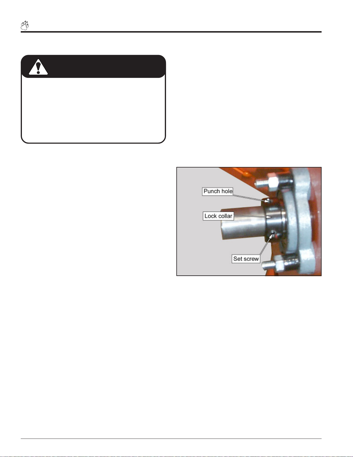
1. Loosen the set screws holding the lock collars on the
2-bolt flange bearings.
2. Use a punch and hammer to tap the lock collars directly opposite of normal rotation.On the front side
tap punch in a CW rotation. On the rear side tap
punch in a CCW rotation
mer, rotate the lock collars in the direction of shaft rotation (i.e. counterclockwise on the rear bearing and
clockwise on the front bearing) and "set" them with
a positive hammer tap. Tighten the lock collar set
screws.
5. Loosen the set screws holding the belt pulley on the
rotor shaft. Move the pulley on the shaft so it is aligned
with the engine drive pulley. The pulley should be moved
the same amount the rotor was moved, only in the opposite direction.
6. Insure the pulley drive key is completely seated under
the pulley and tighten the set screws.
7. Check pulley alignment by laying a straightedge across
the pulley faces. Pulley faces should line up. If not,
repeat steps 9 and 10 until the pulley is lined up.
3. Using a rubber mallet tap the end of the rotor shaft to
obtain 1/16” to 1/8” of an inch clearance. Rotate the
rotor and check the clearance on all chipping blades.
4. Once clearance has been set, the lock collars must be
replaced and retightened. Using a punch and a ham-
Fig. #43 lock collar
Page 34 Bear Cat Chipper Shredder Operator’s Manual
Page 41

GREASING
Service & Maintenance
Use an SAE multi-purpose high temperature grease with
extreme pressure (EP) performance meeting or exceeding
the NLGI # 2 rating for all requirements. Also acceptable is
an SAE multi-purpose lithium based grease.
Care should be taken when re-greasing bearings to not overfill the bearing. Over greasing can lead to overheating and/
or unsealing the bearing seals.
WARNING
To prevent personal injury or property damage: Shut
off engine, disconnect spark plug wire and make sure
that all moving parts have come to a complete stop
before, servicing, adjusting or repairing.
1. Use a hand-held grease gun for all greasing.
2. Wipe grease fitting with a clean cloth before greasing,
to avoid injecting dirt and grit.
3. Replace and repair broken fittings immediately.
4. If fittings will not take grease, remove and clean thoroughly. Also clean lubricant passageway. Replace fitting if necessary.
Fig. #44
Fig. #45
Page 35Bear Cat Chipper Shredder Operator’s Manual
Page 42

Service & Maintenance
REPLACING THE SHREDDER KNIVES
The Rectangular Shredder Knife Kit is a replacement kit to
replace existing dull or damaged knives. The serrated shredder knives are designed to offer long life and can be reversed
if they become dull. To remove the knives or to install a
complete new shredder kit proceed as follows.
WARNING
To prevent personal injury or property damage: Shut
off engine, disconnect spark plug wire and make sure
that all moving parts have come to a complete stop
before, servicing, adjusting or repairing.
IMPORTANT
The serrated edge of the shredder knives should face the
same direction as the cutting edge of the chipper blades.
Never reuse the #10-24 nut and bolt, always install new
parts when repairing. Never reuse shafts or spacers if
they show signs of wear or abuse. Install new ones.
RECTANGULAR SHREDDER KNIFE KIT
TYPICAL SETUP FOR ALL 8 HP MODELS
SHAFT
FOUR
SHAFT
ONE
SHAFT
THREE
SHAFT ONE AND SHAFT THREE ARE SYMMETRICAL
SHAFT TWO AND SHAFT FOUR ARE SYMMETR ICAL
IMPORTANT
SHAFT
TWO
SHAFT THREE
SHAFT FOUR
10
SHAFT ONE
SHAFT TWO
11
8
4
12
7
Fig. #46
SHREDDER KIT PARTS LIST
5
4
9
6
8
11
7
6
1
2
9
5
3
4
12
4
NOTE
This shredder kit uses an improved knife pattern to provide more complete shredding, durability, and easier feeding. Insure the knives and spacers are installed properly
to maintain rotor balance.
INSTALLATION STEPS:
1. Remove belt guards from under engine frame, remove
discharge cover and screen.
2. Remove #10-24 nuts and bolts from knife shafts.
3. Align shaft with 5/8” hole in rear of frame and small hole
in front of machine by the chipper chute.
4. Using a small punch or rod drive the shaft towards and
out the rear 5/8” hole.
5. To assemble, insert shaft through the 5/8” hole in rear of
frame and slide knives and spacers in their proper order
(see drawing) onto the shaft. Install a new # 10-24 nut
and bolt.
6. Repeat steps 3 through 6 to assemble the other three
shafts.
7. When completed install discharge screen, and discharge cover, torque all 3/8” bolts to 33 ft lbs. and test
run machine.
RECTANGULAR SHREDDER KNIFE KIT
TYPICAL SETUP FOR MODEL 70050
SHAFT
SHAFT
FOUR
ONE
SHAFT
TWO
SHAFT
THREE
SHAFT O NE AND SHAF T THREE ARE SY MMETRICAL
SHAFT T WO AND SHAF T FOUR ARE SYMM ETRICAL
IMPORTANT
Fig. #47
8
SHAFT ONE
5
SHAFT TWO
4
SHAFT THREE
6
SHAFT FOUR
7
4
6
7
12
4
3
5
4
ITEM # PART # DESCRIPTION QTY
1 15397 NUT, 10/24 NYLOCK TYPE NM, ZP 4
2 15 459 SKT HD C AP SCW #10- 24 X 1-3/8"PL 4
3 70064 C/S KNIFE SHAFT 4
4 70533 SPACER, 0.75 X 2.170 4
5 70534 SPACER, 0.75 X 0.620 2
6 70535 SPACER, 0.75 X 1.850 2
7 70536 SPACER, 0.75 X 1.240 2
8 70537 SPACER, 1.00 X 1.700 (W/HOLE) 2
9 70538 SPACER, 1.00 X 1.240 (W/HOLE) 2
10 70856 SHREDDING KNIFE, RECTANGULAR 12
11 7096 7 KNIF E, ROTOR BALANCE 2
12 7096 8 S PACER, .81 X .620 2
13 70976 INSTRUCTIONS, WIDE SHRED KIT (THIS INST. SHEET) 1
ITEM # PART # DESCRIPTION QTY
1 15397 NUT, 10/24 NYLOCK TYPE NM, ZP 4
2 15 459 SKT HD C AP SCW #10- 24 X 1-3/8" PL 4
3 70031 KNIFE SHAFT 4
4 70533 SPACER, 0.75 X 2.170 4
5 70534 SPACER, 0.75 X 0.620 2
6 70537 SPACER, 1.00 X 1.700 (W/HOLE) 2
7 70538 SPACER, 1.00 X 1.240 (W/HOLE) 2
8 70856 SHREDDING KNIFE, RECTANGULAR 8
9 71382 KNIFE, ROTOR BALANCE 2
10 71383 INSTRUCTIONS, SHREDDER KIT (THIS INST. SHEET) 1
SHREDDER KIT PARTS LIST
Page 36 Bear Cat Chipper Shredder Operator’s Manual
Page 43

BELT GUIDE ADJUSTMENTS
The 70050 is equipped with a belt guide. The guide aids in
disengaging the chipper/shredder. If problems arise with
engaging and disengaging the unit, follow the instructions
below. These instructions also adjust the lower belt guard.
WARNING
To prevent personal injury or property damage: Shut
off engine, disconnect spark plug wire and make sure
that all moving parts have come to a complete stop
before, servicing, adjusting or repairing.
1. Remove upper belt guard to expose the belt and pulleys.
2. Check to ensure that the engine mounts square to the
chipper body.
Service & Maintenance
3. Loosen set screws and align engine pulley with idler pulley. Using a straight edge, align rotor pulley with engine
pulley. Tighten all set screws.
4. Engage the clutch with the belt in place and check idler
engagement. The idler pulley should impact the belt in
the center of the pulley. All pulleys must be in perfect
alignment. All set screws must be tight.
If idler pulley will not remain in alignment with engine and
rotor pulleys it may be necessary to replace the idler
bracket bushings. Contact the Bear Cat service department for more information.
5. Check the alignment of the belt guide so the finger is
orientated approximately 1/8” from the belt when the clutch
is engaged (see Figure #48). Adjust by loosening the
mounting bolts and repositioning the guide. Retighten
mounting bolts.
6. Reinstall upper belt guard.
7. From underneath, check the alignment of lower belt guard
with a post card (See Fig. #48). With the clutch engaged,
there should be enough room between the belt and the
side of the guard for the card to slide along the belt. With
the clutch disengaged, the card should not be able to
slide. Adjust if necessary.
BELT GUIDE
BELT
LOWER
BELT GUARD
Figure # 48 Belt Guide and Lower Belt Guard
Page 37Bear Cat Chipper Shredder Operator’s Manual
Page 44

Service & Maintenance
REMOVING ROTOR
1. Remove discharge cover, screen and rotor shaft end cap.
2. Loosen the set screws holding the lock collar on the chipper chute side rotor bearing.
3. Using a punch and hammer , tap the lock collar in a direction opposite of normal rotation until loose and remove.
4. Remove guards to allow access to the engine side rotor
bearing.
5. Remove the drive belt.
REPLACING DRIVE BELTS
Check the condition of the drive belts annually or every 30
hours of operation, whichever comes first. Replace the belt
if cracked, frayed or worn. To replace the belt, proceed as
follows:
1. Remove the spark plug wire.
2. Remove all belt guards
6. Loosen the set screws holding the belt pulley on the rotor shaft and remove the pulley .
7. Repeat steps 2 and 3 on the motor side rotor bearing.
8. Remove chipper chute cover bolts and remove chipper
chute with rotor bearing.
9. Remove rotor.
5. Inspect pulleys for wear . Replace the pulleys if they are
cracked or worn so that the belt contact area is not smooth
and flat.
6. Place new belt over pulleys. Do not force or pry the belt
over pulleys as this may cause cord breakage.
7. Reinstall the idler pulley .
8. Check alignment.
3. Remove idle pulley .
4. Slip the drive belt off the pulleys.
TRAILER SERVICE TIPS
1. Check wheel bolt torque every 10 hours of towing use.
2. Check air pressure in tire every 10 hours. Fill to the recommended PSI located on the tire sidewall.
ADDITIONAL SERVICE AND
MAINTENANCE TIPS
1. Service engine according to engine owners manual.
9. Replace belt guards.
3. Check and repack wheel bearings with grease every year.
2. Every 10 hours of operation, all bolts and other fasteners
should be checked for correct torque. .
Page 38 Bear Cat Chipper Shredder Operator’s Manual
Page 45

Service & Maintenance
g
TROUBLESHOOTING
Before performing any of the correction in this troubleshooting chart, refer to the appropriate information contained in this
manual for the correct safety precautions and operating or maintenance procedures. Contact your nearest dealer or the
factory for service problems with the machine.
PROBLEM POSSIBLE CAUSE REMEDY
1. Engine will not start. 1. Improper control settings. 1. Use proper setting.
2. Lack of fuel. 2. Fill fuel tank.
3. Internal Engine Problems. 3. See your dealer.
4. Spark plug disconnected. 4. Connect spark plug.
5. Dirty stale or contaminated gas. 5. Refill gas tank with fresh, clean
unleaded regular gasoline.
2. Engine or rotor stalls or stops. 1. Obstructed discharge. 1. Use branch or similar object to clear
discharge.
2. Plugged Rotor. 2. Clear Rotor.
3. Feeding material too large into shredder. 3. Reduce size of material being fed into
shredder.
3. Engine overheats. 1. Cooling system plugged. 1. Clean cooling fan and fins.
2. Improper oil level. 2. Fill engine to correct oil level. Refer to
the engine owners manual.
5. Hard to feed Chipper requires
excessive power to chip.
6. Shredder requires excessive power
or stalls.
1. Dull chipper blades. 1. Reverse or sharpen blades.
2. Obstructed discharge. 2. Use branch or similar object to clear
dischar
3. Improper blade clearance. 3. Adjust clearance.
1. Obstructed discharge. 1. Use branch or similar object to clear
discharge.
e.
7. Engine stalls or belt squeals when
engaging clutch.
8. Material from chipper wraps
around rotor shaft.
2. Plugged rotor.
3. Wet or green material will not discharge.
1. Engaging clutch too fast. 1. Lift clutch lever more slowly.
2. Plugged Rotor. 2. Clear rotor.
3. Belt tension too loose. 3. Tighten or replace belt.
1. Stringy, green material bypasses chipper
blades.
2. Dull chipper blades 2. Sharpen blades
3. Improper blades clearance.
2. Clear rotor, feed material into shredder
more evenly.
3. Alternately feed dry material or open
shredder adjuster.
1. Rotate branch or material when feeding
to cut completely.
3. Adjust clearance between chipper block
and chipper blades.
Page 39Bear Cat Chipper Shredder Operator’s Manual
Page 46

Service & Maintenance
TROUBLESHOOTING (CONTD.)
PROBLEM POSSIBLE CAUSE REMEDY
9. Excessive vibration while running. 1. Drive system vibration. 1. Check drive belts and pulleys for bad or
worn areas. Check PTO shaft for wear.
Dull chipper blades or shredder knives.
2. Rotor out of balance. 2. Inspect rotor for broken or missing
chipper blades and shredder knives, repair
or replace if needed. Check rotor to see if
it wobbles. Check to see if rotor is
assembled correctly.
3. Chipper blade to anvil clearance is
incorrect.
10. Rotor will not turn. 1. Drive belt too loose or broken. 1. Adjust or replace.
2. Obstructed discharge. 2. Use branch or similar object to clear
3. Plugged rotor. 3. Clear rotor.
11. Cannot engage clutch. 1. Improper belt installation, belt not under
belt guide.
2. Binding of the push rod and clutch spring. 2. Rotate clutch spring.
3. Set chipper blade to anvil clearance to
recommended distance (1/16" to 1/8").
discharge.
1. Install belt properly, install belt under
belt guide.
3. Improper belt tension. 3. Tighten or loosen belt as needed.
12. Excessive belt wear. 1. Not using correct belt. 1. Contact your nearest authorized dealer
to order the correct belt for you chipper
shredder.
2. Pulley(s) damaged or wore. 2. Replace pulley(s).
3. Pulley(s) not in alignment. 3. Align pulley(s) with straight edge.
4. Belt(s) tension too loose. 4. Tighten belt(s) or replace.
13. Trailer sways during towing. 1. Tire air pressure not correct. 1. Check tire sidewall for inflation limits.
Page 40 Bear Cat Chipper Shredder Operator’s Manual
Page 47

5.5 HP 3” Chipper/Shredder (Model 70050 & 70050S)
BEARCAT MODEL 70050
5.5 HP
5 HP CHIPPER/SHREDDER
SPECIFICATIONS
22.75
[577.85]
Specifications
41.46
[1052.96]
[961.80]
37.87
21.72
[551.59]
22.16
[562.94]
[238.96]
[508.89]
MAX. MATERIAL
DIA. ALLOWED
3 INCHES [76]
9.41
20.04
HOPPER SIZE
12 X 22 INCHES
[305 X 560]
28.12
[714.17]
15.50
[393.70]
25.28
[642.04]
70050 - 3" CHIPPER SHREDDER W/ 5 HP BRIGGS & STRATTON ENGINE
1.) 3" [76 mm] CAPACITY CHIPPER.
2.) 2 REVERSABLE TOOL STEEL CHIPPER BLADES.
3.) CAN ACCEPT 4 SIZES OF DISCHARGE SCREENS:
FINE, (.375" DIA. [9.5MM] HOLES)
MEDIUM, (.75" DIA. [19 MM] HOLES)
COARSE, (1.50" DIA. [38 MM] HOLES)
WET DEBRIS SCREEN, (QTY. 2 - Ø1.50 [38 MM] X
3.25 [82 MM] SLOTS, QTY. 2 - Ø1.50 [38 MM] X 7.38
[187 MM SLOTS, AND QTY. 1 - Ø1.50 [38 MM] X
9.50 [241 MM] SLOT).
5.5 HP
4.) 8 SERRATED REVERSABLE SHREDDER KNIVES.
5.) HEAVY DUTY WELDED STEEL CONSTRUCTION FRAME.
6.) 12" [304 MM] X 22" [558 MM] SHREDDER THROAT
OPENING.
ENGINE SPECIFICATIONS:
SEE THE ENGINE OWNER / OPERATORS MANUAL THAT
CAME WITH YOUR MODEL OF CHIPPER SHREDDER.
7.) 70050 - IS EQUIPPED WITH A 5 HP BRIGGS &
STRATTON ENGINE
INTEK ENGINE
5.5 HP
Page 41Bear Cat Chipper Shredder Operator’s Manual
Page 48

Specifications
8 Hp 3” Chipper/Shredder (Models 70080(S), 70085, 70180(S), 70380(S), 70385)
BEARCAT MODELS:
70080
70085
70180
70380
70385
8 HP CHIPPER/SHREDDER
SPECIFICATIONS
22.16
[562.94]
37.87
[961.80]
22.75
[577.85]
HOPPER SIZE
12 X 22 INCHES
[305 X 560]
MAX. MATERIAL
DIA. ALLOWED
3 INCHES [76]
15.50
[393.70]
41.46
[1052.96]
9.27
[235.51]
21.72
20.04
[508.89]
[551.59]
3" CHIPPER SHREDDER W/ 8 HP ENGINE
1.) 3" [76 mm] CAPACITY CHIPPER.
2.) 2 REVERSABLE TOOL STEEL CHIPPER BLADES.
3.) CAN ACCEPT 4 SIZES OF DISCHARGE SCREENS:
FINE, (.375" DIA. [9.5MM] HOLES)
MEDIUM, (.75" DIA. [19 MM] HOLES)
COARSE, (1.50" DIA. [38 MM] HOLES)
WET DEBRIS SCREEN, (QTY. 2 - Ø1.50 [38 MM] X
3.25 [82 MM] SLOTS, QTY. 2 - Ø1.50 [38 MM] X 7.38
[187 MM SLOTS, AND QTY. 1 - Ø1.50 [38 MM] X
9.50 [241 MM] SLOT).
4.) 12 SERRATED REVERSABLE SHREDDER KNIVES.
5.) HEAVY DUTY WELDED STEEL CONSTRUCTION FRAME.
28.12
[714.17]
25.28
[642.04]
6.) 12" [304 MM] X 22" [558 MM] SHREDDER THROAT
OPENING.
ENGINE SPECIFICATIONS:
SEE THE ENGINE OWNER / OPERATORS MANUAL THAT
CAME WITH YOUR MODEL OF CHIPPER SHREDDER.
7.) 70080 - IS EQUIPPED WITH A 8 HP BRIGGS &
STRATTON ENGINE
8.) 70085 - IS EQUIPPED WITH A 8 HP BRIGGS &
STRATTON ENGINE W/ ELECTRIC START
9.) 70180 - IS EQUIPPED WITH A 8 HP BRIGGS &
STRATTON INDUSTRIAL COMMERCIAL ENGINE
10.) 70380 - IS EQUIPPED WITH A 8 HP HONDA
ENGINE
11.) 70385 - IS EQUIPPED WITH A 8 HP HONDA
ENGINE W/ ELECTRIC START
Page 42 Bear Cat Chipper Shredder Operator’s Manual
Page 49

8 Hp 3” T owable Chipper/Shredder (Model 70580 (S))
BEARCAT MODEL 70580
8 HP TOWABLE CHIPPER/SHREDDER
SPECIFICATIONS
24.64
[625.73]
Specifications
54.74
[1390.40]
8.76
[222.48]
16.79
[426.34]
HOPPER SIZE
12x22 INCHES
[305 X 560]
24.00
[609.60]
MAX. MATERIAL
DIA. ALLOWED
3 INCHES [76]
33.45
[849.60]
10.31
[261.98]
45.30
58.12
[1476.20]
33.67
[855.29]
[1150.52]
70580 - 3" TOWABLE CHIPPER SHREDDER W/ 8 HP HONDA ENGINE
1.) 3" [76 mm] CAPACITY CHIPPER.
2.) 2 REVERSABLE TOOL STEEL CHIPPER BLADES.
3.) CAN ACCEPT 4 SIZES OF DISCHARGE SCREENS:
• FINE, (.375" DIA. [9.5MM] HOLES)
• MEDIUM, (.75" DIA. [19 MM] HOLES)
• COARSE, (1.50" DIA. [38 MM] HOLES)
• WET DEBRIS SCREEN, (QTY. 2 - Ø1.50 [38 MM] X
3.25 [82 MM] SLOTS, QTY. 2 - Ø1.50 [38 MM] X 7.38
[187 MM SLOTS, AND QTY. 1 - Ø1.50 [38 MM] X
9.50 [241 MM] SLOT).
4.) 12 SERRATED REVERSABLE SHREDDER KNIVES.
5.) HEAVY DUTY WELDED STEEL CONSTRUCTION FRAME.
6.) 12" [304 MM] X 22" [558 MM] SHREDDER THROAT
OPENING.
ENGINE SP ECIFICATIO NS:
SEE THE ENGINE OWNER / OPERATORS MANUAL THAT
CAME WITH YOUR MODEL OF CHIPPER SHREDDER.
7.) 70580 - IS EQUIPPED WITH A 8 HP HONDA ENGINE
Page 43Bear Cat Chipper Shredder Operator’s Manual
Page 50

BOLT TORQUE
CHECKING BOLT TORQUE:
The table shown below is for reference purposes only and its use by anyone is entirely voluntary , unless otherwise noted.
Reliance on its contents for any purpose is at the sole risk of that person. BearCat Co. is not responsible for any loss claim
or damage arising therefrom. In developing these tables, BearCat has made a determined effort to present the contents
accurately.
SAE - 8SAE - 2ASAE - 5
ENGLISH TORQUE SPECIFICATION
Bolt
Diameter
"A"
1/4" 7.5 5.5 11 8 16 12
5/16" 15 11 23 17 34 25
3/8" 27 20 41 30 61 45
7/16" 41 30 68 50 95 70
1/2" 68 50 102 75 149 110
9/16" 97 70 149 110 203 150
5/8" 122 90 203 150 312 230
3/4" 217 160 353 260 515 380
7/8" 230 170 542 400 814 600
1" 298 220 786 580 1220 900
1-1/8" 407 300 1085 800 1736 1280
1-1/4" 570 420 2631 1940 2468 1820
SAE 2 SAE 5 SAE 8
N.m Ft-lb N.m Ft-lb N.m Ft-lb
A
Bolt Torque* (UNC)
METRIC TORQUE SPECIFICATION
Bolt
Diameter
"A"
4.8 8.8 10.9
Bolt Torque*
12.9
N.m Ft-lb N.m Ft-lb N.m Ft-lb N.m Ft-lb
M30.50.4 - - - - - M432.2 - - - - - M554 - - - - - M6 6 4.5 11 8.5 17 12 19 14.5
M8 15 11 28 20 40 30 47 35
M102921554080609570
M1250379570140105165120
M14 80 60 150 110 225 165 260 190
M16 125 92 240 175 350 255 400 300
M18 175 125 330 250 475 350 560 410
M20 240 180 475 350 675 500 800 580
M22 330 250 650 475 925 675 1075 800
M24 425 310 825 600 1150 850 1350 1000
M27 625 450 1200 875 1700 1250 2000 1500
Torque figures indicated above are valid for non-greased or non-oiled threads and heads unless otherwise specified. Therefore, do not grease or
oil bolts or capscrews unless otherwise specified in this manual. When using locking elements, increase torque values by 5%.
* Torque value for bolts and capscrews are identified by their head markings.
Page 44 Bear Cat Chipper Shredder Operator’s Manual
Page 51

)
(
)
SPECIAL TORQUE REQUIREMENTS
SPECIAL TORQUE REQUIREMENTS
LOCATION ON MACHINE HARDWARE DESCRIPTION
ON ROTOR PLATE, BLADE MOUNTING BOLTS 5/16" X 1" HEX HD. GRADE 8 BOLTS (QTY 8
ON ROTOR KNIVE SHAFTS 10-24 X 1-1/8" SCREW
B
A
QTY 6
Specifications
TORQUE
(UNIFIED INCH))
20 ft-lbs 27 N.m
36 in-lbs 4 N.m
TORQUE
(METRIC)
A
B
A
B
Page 45Bear Cat Chipper Shredder Operator’s Manual
Page 52

HEALTH WARNING
GASOLINE, DIESEL, AND
OTHER PETROLEUM PRODUCTS
Harmful or fatal if swallowed.
Long-term exposure to vapors has caused cancer in laboratory animals.
• Avoid prolonged breathing of vapors.
• Keep face away from nozzle and gas tank/container
opening.
• Never siphon by mouth.
Failure to use caution may cause serious injury or illness.
WARNING
CHEMICALS KNOWN TO THE STATE OF CALIFORNIA TO CAUSE CANCER, BIRTH DEFECTS, OR
OTHER REPRODUCTIVE HARM ARE FOUND IN
GASOLINE, DIESEL, CRUDE OIL, AND MANY OTHER
PETROLEUM PRODUCTS AND THEIR VAPORS, OR
RESULT FROM THEIR USE.
READ AND FOLLOW LABEL DIRECTIONS AND USE
CARE WHEN HANDLING OR USING ALL PETROLEUM
PRODUCTS.
ENGINE EXHAUST FROM THIS PRODUCT CONTAINS
CHEMICALS KNOWN TO THE STATE OF CALIFORNIA TO CAUSE CANCER, BIRTH DEFECTS, OR
OTHER REPRODUCTIVE HARM.
Crary Company
A Division of TerraMarc Industries
237 12th St. NW • P.O. Box 849
West Fargo, ND 58078-0849
(701)282-5520 • FAX: (701)282-9522
www.bearcatproducts.com
Manufactured in the
United States of America
by Crary Company
www.terramarc.com
 Loading...