

Page 1

Layla
by
®
Owner’s Manual Version 1.6 for PC
Layla is designed and manufactured in the U.S. by Echo Corporation
1
Page 2

Important Safety Instructions
1. Read Instructions
instructions before operating this product.
2. Retain Instructions
be retained for future reference.
3. Heed Warnings
should be followed.
4. Follow Instructions
followed.
5. Moisture
- Water and moisture are detrimental to the continued good
health of Layla. Do not install or operate Layla near sources of water or
moisture such as sinks, damp basements, leaky roofs, etc.
6. Heat
- Layla should be situated away from sources of heat such as heaters
or radiators.
7. Power Sources
power source indicated in this documentation or on Layla. If you are unsure
about the type of power at your location, contact your local power company.
8. Grounding
- Precautions should be taken so that the grounding
capabilities of the Layla are not undermined. This equipment is provided
with a cord having an equipment grounding conductor and grounding plug.
This plug must be plugged into an outlet that is properly installed and
grounded in accordance with all local rules and ordinances. Do not modify
the plug provided with the equipment. If the plug will not fit into your
outlet, have a proper outlet installed by a qualified electrician.
9. Power Cord Protection
they are unlikely to be walked on or pinched by items placed upon or
against them. Pay particular attention to protecting the plugs, outlets, and
the point at which the cord exits Layla.
- Be sure to read all of the safety and operating
- The safety instructions and owner's manual should
- All warnings on Layla and in the Owner's Manual
- All operating and use instructions should be
- This unit should be operated only from the type of
- Power supply cords should be routed so that
2
Page 3

10. Servicing
- Do not attempt to service this unit yourself, as opening the
case will expose you to hazardous voltage or other dangers. All servicing
should be referred to qualified service personnel.
11. Damage Requiring Service
- Unplug this unit and refer it to a qualified
service technician when any of the following occur:
a) Objects have fallen or liquid has spilled into the unit
b) The product has been exposed to rain or water
c) The product does not operate normally or when a marked change
in performance is noticed
d) The product has been dropped or damaged in any way
3
Page 4

Sending in your registration card – or registering online at
allows us to register key information so that we may handle problems faster and inform you of advance
information on upgrades and other news. Thanks in advance for filling out your registration card and
sending it to us. We hope you enjoy your Echo product.
http://www.echoaudio.com/register.html
-
Limited Warranty
Echo Corporation warrants this product, when purchased at an Authorized Echo Dealer in the United States
of America, to be free of defects in materials and manufacturing workmanship for a period of one year from
the date of original purchase. During the warranty period Echo shall, at its option, either repair or replace
any product that proves to be defective upon inspection by Echo. Final determination of warranty coverage
lies solely with Echo. Echo reserves the right to update any unit returned for repair, and reserves the right
to change or improve the design of the product at any time without notice.
This is your sole warranty. Echo does not authorize any third party, including any dealer or sales
representative, to assume any liability on behalf of Echo or to make any warranty for Echo.
Service and repairs of Echo products are to be performed only at the factory (see below) unless otherwise
authorized in advance by the Echo Service Department. Unauthorized service, repair or modification will
void this warranty.
To obtain factory service:
Contact Echo Corporation at (805) 684-4593, 9AM to 5PM Monday through Friday (Pacific Time). If
necessary, you will be given a return authorization number. Products returned without an RA number will
be refused. Echo may, at its option, require proof of the original date of purchase in the form of a dated
copy of the original authorized dealer’s invoice or sales receipt.
Pack the product in its original shipping carton and attach a description of the problem along with your
name and a phone number where Echo can contact you if necessary. Ship the product insured and freight
prepaid to:
Echo Corporation
6460 Via Real
Carpinteria, CA 93013
DISCLAIMER AND LIMITATION OF WARRANTY
Echo Corporation makes no other warranties, express, implied, or otherwise, regarding Echo products, and
specifically disclaims any warranty for merchantability or fitness for a particular purpose. The exclusion of
implied warranties is not permitted in some states and the exclusions specified herein may not apply to you.
This warranty provides you with specific legal rights. There may be other rights that you have which vary
from state to state.
In no event will Echo Corporation be liable for any lost profits, or for any consequential, direct or indirect
damages, however caused and on any theory of liability, arising from this warranty and sale.
©1999 by Echo Corporation
6460 Via Real
Carpinteria, CA 93013
Echo® is a registered trademark of Echo Corporation
®
, Gina® and Darla® are trademarks of Echo Corporation
Layla
Windows
®
, Windows ‘95®, Windows ‘98®, and Windows NT® are registered trademarks of Microsoft, Inc.
4
Page 5

Table of Contents
Introduction
What You Should Have Received in the Layla Box 7
System Requirements 7
Layla Installation
8
7
Running the Echo Reporter Software 8
The ECHODEL Program 12
System Sounds 13
Installing the Layla Hardware 14
Connecting to Layla’s Rack-mount Interface 16
Installing the Layla Software Drivers 21
Layla Audio Input & Output Devices 24
The Echo Console
The File Menu 27
The Edit Menu 27
The Session Menu 28
The Monitors Menu 30
Console Controls 30
EasyTrim Automatic Gain Control 31
Monitor Controls 32
Output Controls 33
26
Adjusting Record and Playback Levels 34
Setting Clock Sources and Destinations 34
Synchronizing Multiple Devices 35
Console Keyboard and Mouse Shortcuts 37
Additional Configuration Settings 38
The Monitor During Playback Control 39
Selecting The S/PDIF Output Mode 39
SAW Compatibility Mode 40
Show Echo Console on the Taskbar 40
MIDI Time Code Settings 41
The Clocks Settings 43
ASIO Driver Installation
44
5
Page 6

Table of Contents
Installing Cool Edit Pro
Cool Edit Pro: Assigning Layla’s Inputs & Outputs
Cool Edit Pro: Optimizing Multitrack Performance
Contacting Customer Service
Appendix A:
Appendix B:
Appendix C:
Appendix D:
Appendix E:
The Reporter Troubleshooting Guide 50
General Troubleshooting Guide
Resolving Interrupt Conflicts 55
Introduction to Digital Recording 60
Specifications 64
Index
Special Edition
45
46
47
49
52
65
6
Page 7

Introduction
Thank you for choosing the Layla 20-bit Multitrack Digital Audio Recorder.
We think you’ll find Layla to be an extremely flexible, high-performance
tool for your computer-based hard disk recording system.
What You Should Have Received in the Layla Box
When you opened the Layla box, you should have found the following:
•
•
•
•
•
•
System Requirements
In order to use Layla you’ll need the following:
A Layla PCI card wrapped in an anti-static cover
A Layla rack-mount audio interface box
A Layla digital control connector cable
A compact disc containing the Layla Windows 95/Windows 98
Drivers, the Echo Reporter
Software’s Cool Edit Pro
and editing software, and demo versions of digital audio recording,
editing, and processing software from a variety of manufacturers
The Layla Owner’s Manual
Four adhesive backed rubber feet and four mounting screws with
collars.
system analysis software, Syntrillium
Special Edition multitrack recording
• An IBM-PC or compatible computer with PCI architecture
expansion slots (version 2.1 PCI BIOS), a genuine Intel Pentium or
faster CPU, a motherboard with an Intel chipset, and minimum
64Mb RAM (more highly recommended) running Windows 95 or
Windows 98
• A fast, high-capacity IDE or SCSI hard disk drive
• Peripheral audio equipment, such as a mixer, power amplifier, DAT
recorder, musical instruments, etc.
7
Page 8

Layla Installation
Complete Layla installation consists of performing a system check using the
Echo Reporter
software, installing the Layla PCI card, connecting the
rack-mount audio interface to the card, installing the Layla Windows drivers
into your system and, if necessary, installing a multitrack audio
recording/editing application.
Running the Echo Reporter Software
The Reporter is designed to provide you with an analysis of your computer
system’s audio capabilities and its ability to work successfully with Layla.
The program looks at such things as your BIOS version, your interrupt
assignments, and your hard disk’s transfer rate. The Reporter will perform a
limited series of compatibility tests.
will work with Darla.
The only way to be sure is to install the card in your
system and see if it works. Please note that we only support Intel CPUs and
motherboards with an Intel chipset. Your system may or may not work with
other CPUs or chipsets.
Be sure to run the Reporter before attempting to install Layla
help you avoid installation problems down the road. To run the Reporter,
simply double-click on the
Install Reporter
of the Layla CD-ROM. This will install the program onto your hard disk.
The Reporter will then show up under the
Audio Utilities
. Select The
Echo Reporter
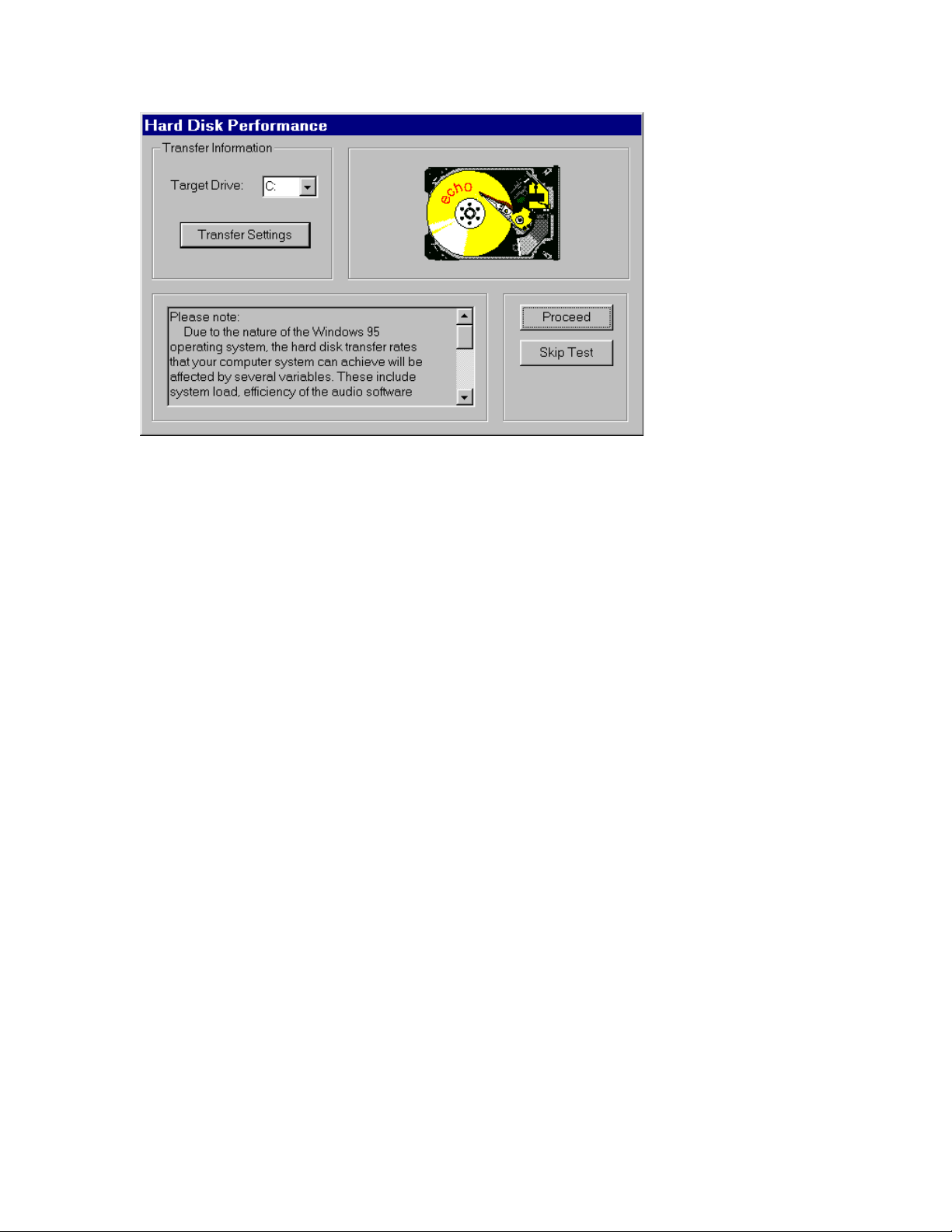
Once the program launches, you’ll see the
screen. Press the
Proceed
button to initiate the disk speed test. This test will
tell you if your hard disk is fast enough to support multitrack digital audio
and, if so, approximately how many tracks of record and playback you’ll be
able to achieve.
It cannot guarantee that your system
as it can
icon in the
Start
menu,
Reporter
directory
Programs, Echo
to launch the program.
Hard Disk Performance
test
8
Page 9
After the test is completed you’ll see a results screen. Many of the
parameters on the screen are interactive; you can change them to see how
your disk performs under different conditions.
For example, in the upper right corner of the screen you can see how large
your hard disk is and how many minutes of recording time it will provide
for a mono track recorded at 44.1kHz with 16-bit resolution. (Times are
expressed in Hours: Minutes: Seconds.) Change the
Number of Tracks
field to “2” and you’ll see the maximum length available for a stereo track.
Change the field to “8” and you’ll see the maximum length you’ll have for
an eight-track opus. Naturally, these multitrack readouts presume
uninterrupted, linear tracks. Your music is likely to contain numerous
snippets of data (e.g., the background vocals will only appear at specific
moments in time, not continuously throughout the whole tune), so, generally
speaking, you’ll be able to create longer pieces than the readout indicates.
9
Page 10
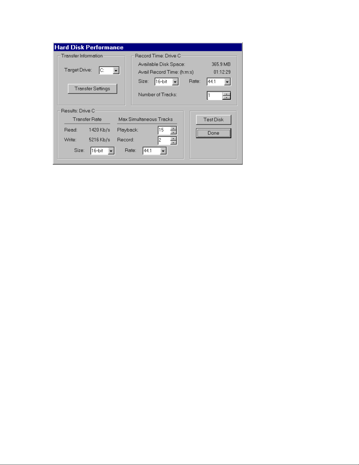
You can adjust the parameters on the Hard Disk Performance
screen to view your disk’s record and playback capabilities at
various sample rates and bit-resolutions.
You can also change the
Number of Tracks
fields. Though the original test was performed with
Size
(bit-resolution),
Rate
(sample rate), and
default values of 16-bit 44.1kHz, you can easily see your disk’s
performance reading and writing, say, 24-bit 48kHz data simply by selecting
those values in the appropriate fields.
About the
Tracks
heading:
Playback:
Record:
and
fields under the
Max Simultaneous
•
At the basic level, these two fields show you how many simultaneous
tracks of playback and recording your system will support. For example, if
the readout was “15” for the
Playback:
field and “8” for the
Record:
field, that means your system is capable of playing back 15 tracks while
simultaneously recording 8 tracks. Note, however, that the Playback: and
Record: fields are interrelated: as you change the value in one field, the
value in the other field is affected. In other words, the values are dynamic.
You can get a feel for how much overall read/write bandwidth you have by
adjusting the values in the two fields. By lowering the number of record
tracks, you’ll see the number of simultaneous playback tracks increase.
10
Page 11

Similarly, by lowering the number of playback tracks, you’ll see the
number of record tracks increase.
•
The readouts will generally show that you have fewer record tracks
available than playback tracks. This is because writing data to a hard disk
is a slower process than reading it back (due to the verify routines used
when writing to disk).
•
The values you see should not be taken as absolute. There are numerous
conditions that come into play when determining overall performance,
from operating system overhead to the audio application you’re running
(different programs use different file management schemes, with some
more efficient than others). The readouts you get from the Reporter are
meant to be taken as general guidelines. When you’re actually running
your audio software, you may get better results than the Reporter tells
youso don’t run out and buy new hardware just because the Reporter
tells you your system seems a bit on the weak side. Use your audio
application in real-world conditions, then make the determination if your
system can keep up with your needs.
(Conversely, if the Reporter tells you things look really bad, don’t waste
your time trying to do any serious work. If your hard disk is too slow or too
small, you’ll save yourself a lot of frustration by upgrading to a big fast disk
right out of the chutethat is, unless you like random skipping and hiccups
in your music. And don’t skimp on RAM: we suggest a minimum of 64 MB,
and load up from there. When it comes to multitrack digital audio, there’s
no such thing as too much RAM.)
When you’re finished playing around with the disk test parameters, click
Done
to get to the Summary screen. There you’ll see a complete analysis of
the results of the tests, an explanation of those results, and recommended
actions (if any are required). If the Reporter alerted you to any problems,
you should check the appendixes at the back of the Layla Owner’s Manual
for help in isolating the cause of your difficulty and finding a solution.
11
Page 12
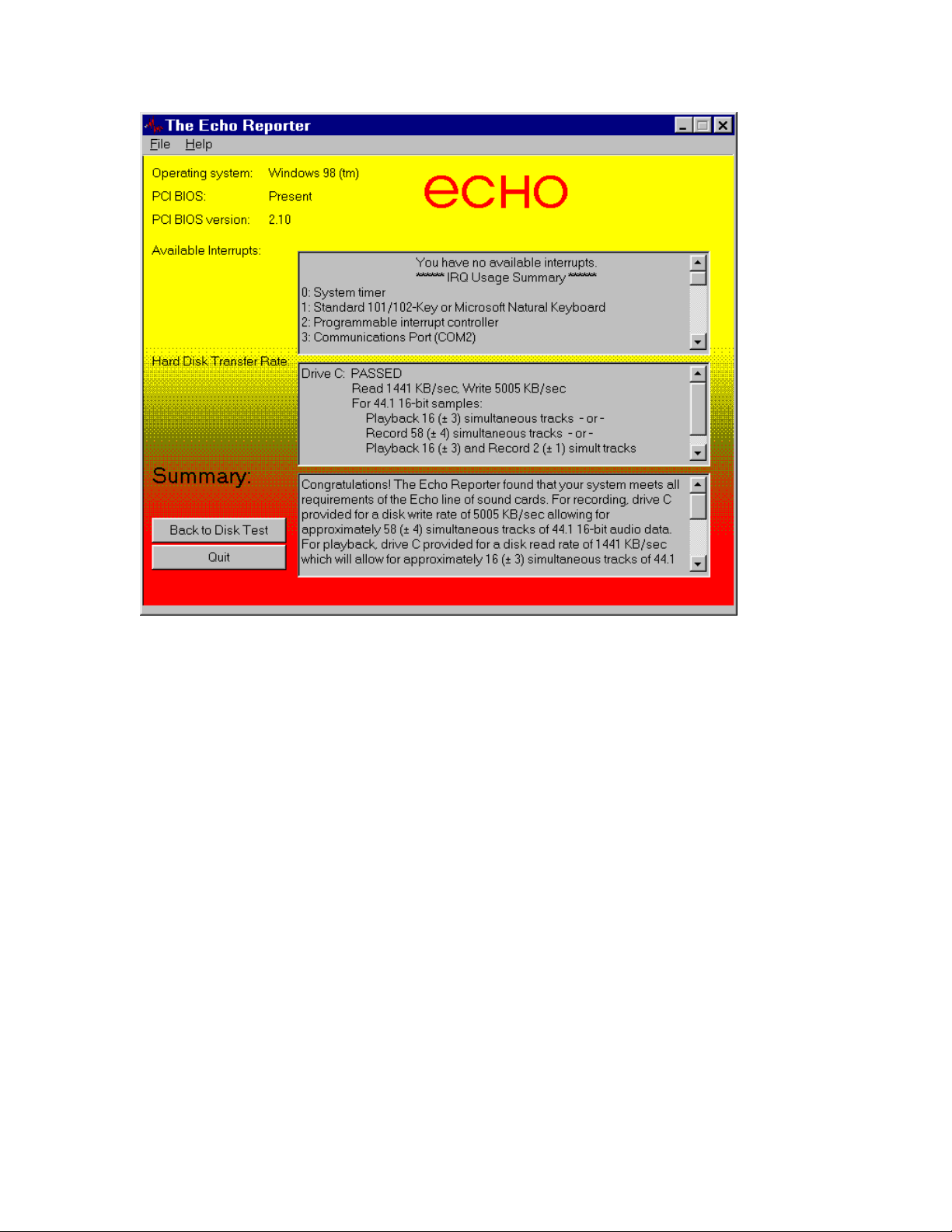
The Summary screen tells you if your system can support multitrack audio
recording as well as alerting you to potential problems.
If your system passed the Echo Reporter test, it’s time to move on to the
next phase of installation.
The ECHODEL Program
If you have previously installed an Echo audio card, such as a Gina, Darla,
or Layla, it will be necessary to remove the old drivers before adding your
Layla. If you are uncertain as to whether any of these cards have ever
previously been installed in your computer, it might be wise to go ahead and
perform the remainder of this step anyway. It will not harm any of your
existing system files, and doing so will ensure that you are performing a
“clean” installation. On the CD that accompanied your Layla is a program
called ECHODEL.EXE. Simply run this program, following the program’s
instructions. It will make the appropriate deletions and update your
Windows system files. (NOTE: It is necessary to run the ECHODEL
12
Page 13

program anytime you add an Echo audio card to your system, even if you
are merely exchanging one card for an identical one (such as during a
warranty exchange). Be sure to restart Windows after you run the
ECHODEL program.
System Sounds
There is one final step to perform before installing the Layla hardware. We
suggest that you turn off your Windows system sounds prior to installing
Layla. Because most system sounds are sampled at very low sample rates,
typically 8 to 11 KHz, each time they are played it will cause the sample
rate clock on Layla to reset to the slower speed
To turn off the system sounds, first go to the Windows
which can be found under
panel you will find an icon titled “
Settings
from the
Sounds
icon, you will see a window labeled “
Schemes
Start
”. After double clicking on this
” near the bottom of the
Control Panel
,
button. On the control
screen. Click on the small down arrow to the right of the combo-box and
select the “
No Sounds
” option. Then click on the Ok button.
13
Page 14

Installing the Layla Hardware
Once you have run the Reporter software, have verified that there are no
problems with your system, and have removed any old driver software with
the ECHODEL program, it is time to install Layla into your computer.
IMPORTANT - Unplug your computer and detach all peripherals before
proceeding with the following steps.
1. Remove your computer’s cover. This operation differs from computer to
computer. Refer to your computer’s manual for a further explanation of
this step if necessary.
2. Select the slot into which you will install the Layla card. The Layla card
is PCI architecture. Inside your computer you will likely find two types of
expansion slots, ISA and PCI. The PCI slots will be shorter and have a
higher connector pin density than the ISA slots. You may use any of the
available PCI slots in your computer for Layla. Unscrew and remove the
bracket covering the expansion slot where you would like to install Layla.
Put the screw in a safe place, as you will need it later to complete the
installation.
3. Insure that you have fully discharged all static electricity from your body
before handling the Layla card. This can be done through the use of a
grounding strap or, more simply, by touching your bare hand to the metal
casing of the computer’s power supply. (For this latter method to work,
the computer must be plugged in, though not turned on. After you’ve
discharged your static, unplug the computer before proceeding to the next
step.)
4. Remove the Layla card from its protective anti-static bag. Handle the card
carefully by its edges and insert it into the selected expansion slot. Insure
that the card’s edge connector (the protruding edge with the gold leads) is
seated firmly into the slot. Centering the card over the slot and using a
gentle rocking motion while pushing downward into the slot generally
works well. Be careful not to force the card into the slot, or bend or twist
it while it is being inserted, as this could result in the card being damaged.
14
Page 15

5. Use the screw removed earlier from the protective backplate to attach the
metal bracket at the back of the Layla card to the computer’s rear panel.
6. Replace the computer’s cover and secure it. Reattach its power supply
cord and reconnect any peripherals that you may have removed prior to
beginning the Layla installation.
7. Locate the Layla rack-mount interface and the 25-pin audio connector
cable. Securely mount the interface into your equipment rack. If you will
not be mounting the box in a rack, remove the backing from the four
rubber feet and place one in each bottom corner of the interface unit.
Then be sure to locate the rack-mount box in a secure location.
Plug one end of the cable into the 25-pin connector on the Layla card that
now protrudes through the back panel of your computer, and secure the
cable using the built-in screws located on both sides of the connector.
Attach the other end of the cable to the rear of the interface and fasten the
cable securely with the screws.
Caution: Never connect the rack-mount interface to the computer while
either the interface or your computer is turned on.
8. You can now attach external audio devices to the rack-mount box. Layla
can accommodate eight analog input signals and can generate ten
independent analog output signals. In addition, Layla provides word
clock/superclock sync, MIDI in/out/through, and stereo S/PDIF digital
input and output. Additional information on attaching external devices to
Layla may be found in the
Interface
section. (NOTE: When connecting devices to the S/PDIF jacks
Connecting to Layla’s Rack-mount
on Layla, do not use standard RCA audio cables. For reliable S/PDIF
operation, 75ohm coaxial video cables are recommended).
All of the analog and digital inputs and outputs on Layla are simultaneously
active, allowing you to record up to 10 channels of audio (eight analog and
two digital) while playing back twelve channels (ten analog and two
digital).
15
Page 16
Connecting to Layla’s Rack-mount Interface
The back panel of Layla’s rack-mount interface contains a wide variety of
connections that allow great flexibility in the operation of Layla. To achieve
the optimal performance with Layla, it is critical that the appropriate cabling
and connectors are used.
Analog Inputs and Outputs
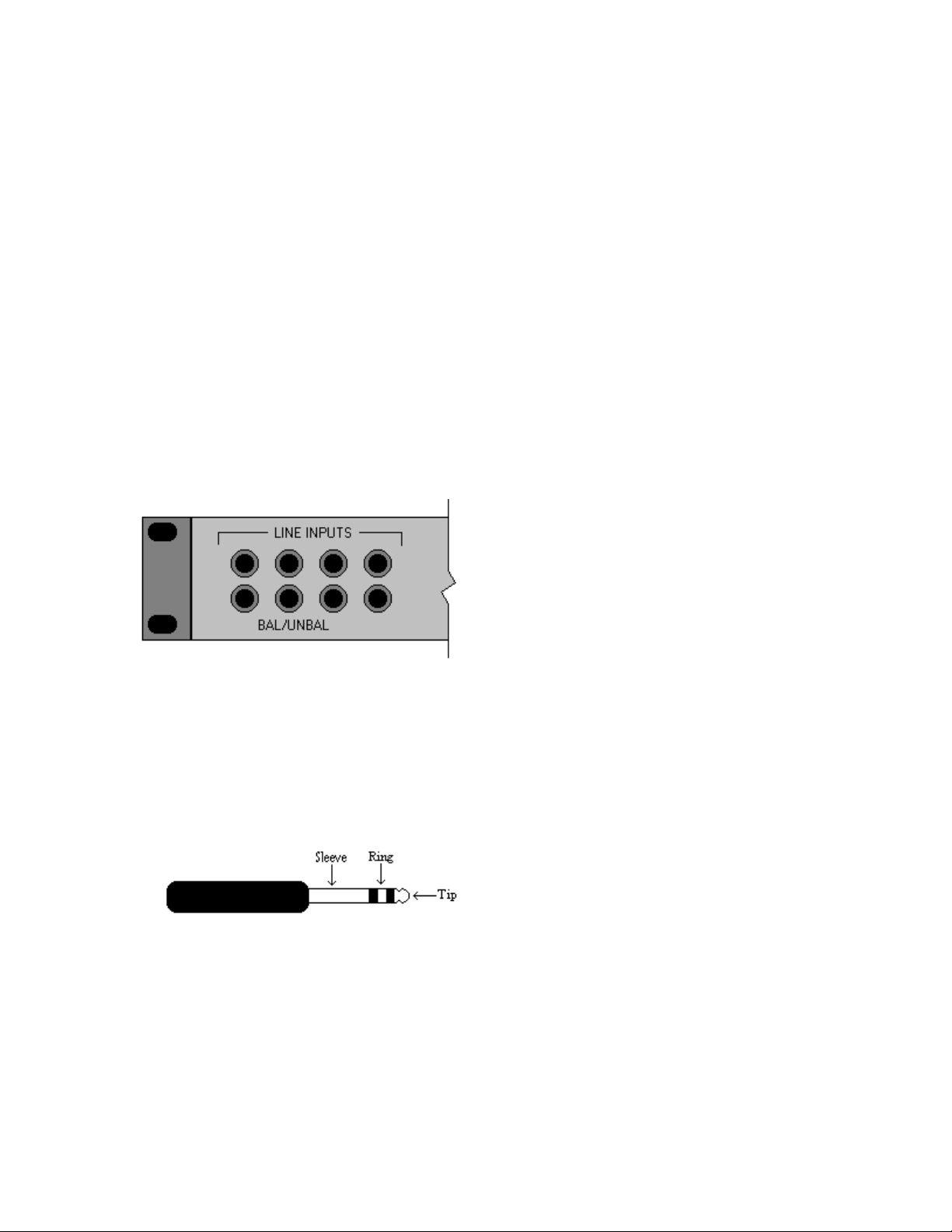
Layla has eight analog inputs and ten analog outputs on the back panel, as
well as two inputs on the front (the two inputs on the front are alternate
connectors for channels 7 and 8 on the back of Layla. When you plug into
the front panel inputs, the corresponding back panel inputs are disabled).
These connections can accept balanced or unbalanced signals.
An unbalanced signal contains two components, a ground signal and a “hot”
or active signal. A balanced signal contains these two components with the
addition of a second active channel that is 180 degrees out of phase from the
primary signal. In this way, a balanced signal can eliminate any noise that
may be introduced into the audio signal during transmission. The connectors
used for the analog inputs and outputs on Layla are TRS (tip, ring sleeve).
The three sections of a TRS connector are used to transmit the three
components of a balanced signal. Layla will also accommodate the two
conductor unbalanced style connector.
16
Page 17
The Host Connector
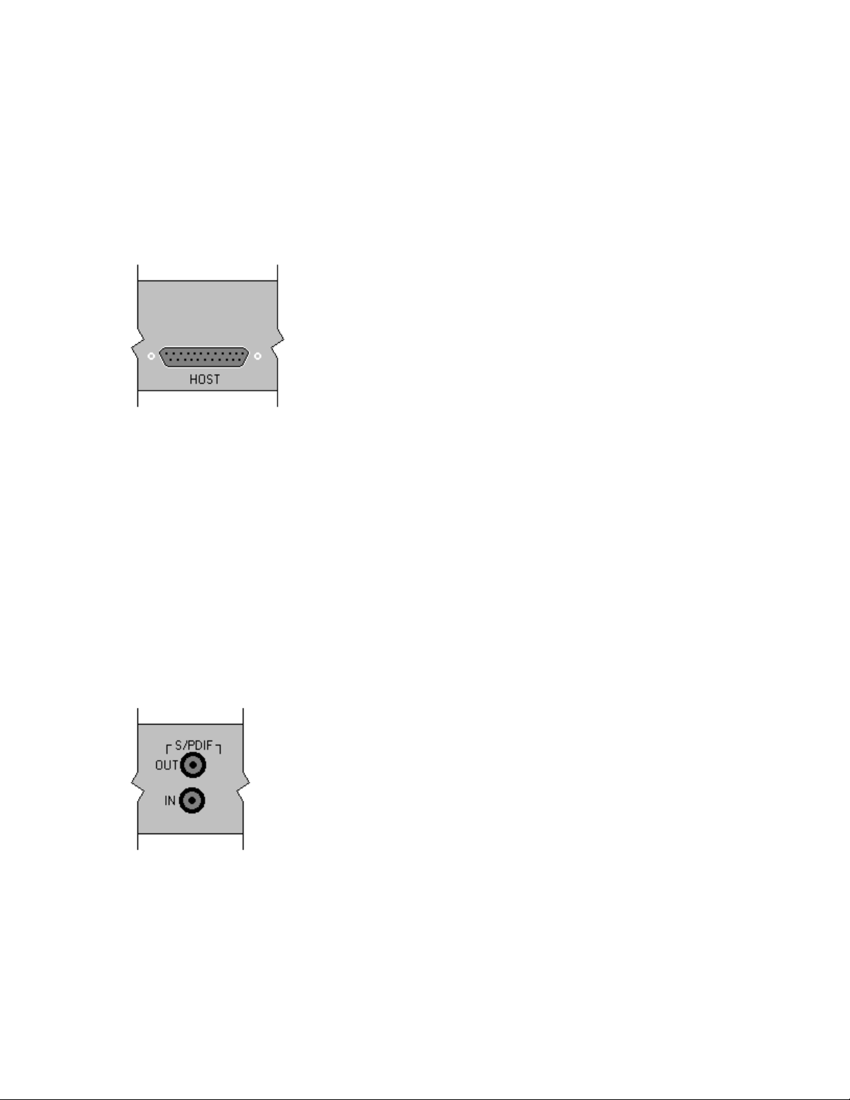
Next to the analog inputs and outputs is a connector labeled
HOST
. This
connector is known as a DB-25, and is commonly used on PCs for the
printer port. It is the point at which the audio interface connects to the Layla
PCI card inside your computer.
A cable was supplied with your Layla for this purpose. This cable is
manufactured to certain specifications, and if necessary, should only be
replaced with a cable that meets specification IEEE-1284. Layla is designed
for use with cables of up to 15 feet in length. Cables in excess of 15 feet
may cause loss of data and/or diminished system performance.
S/PDIF
Next to the
out
. S/PDIF is used to transmit digital data among digital audio devices.
Host
connector is a pair of connectors labeled
S/PDIF in
and
S/PDIF data can use the full 24-bit sample width used internally on Layla.
When connecting devices to the S/PDIF jacks on Layla, the use of standard
RCA audio cables is not recommended. For reliable S/PDIF operation,
75ohm coaxial (RG59) video cables are recommended.
17
Page 18
Word Clock
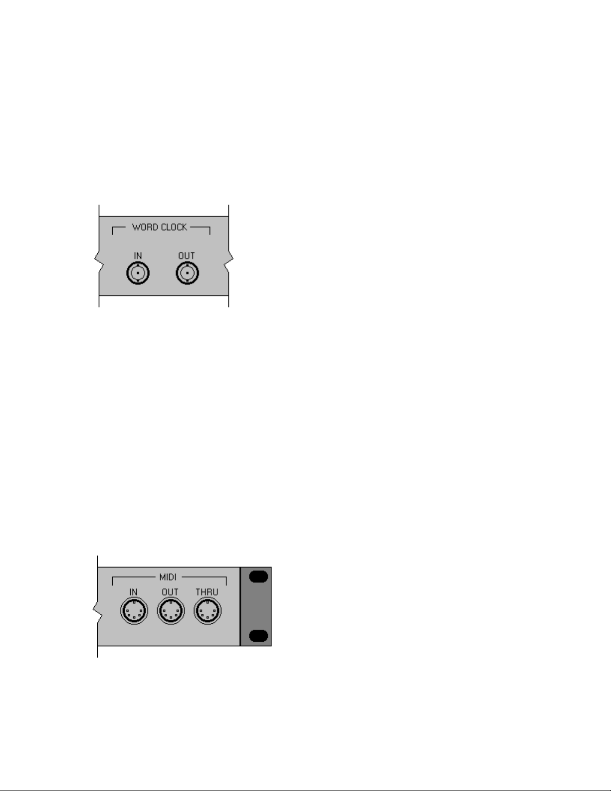
Next to the S/PDIF ports are the
Word Clock
connectors. These connectors
allow you to synchronize one Layla to another Layla or to other digital
audio devices. In addition to a standard word clock signal, these connectors
also allow you to synchronize using the superclock format, which is 256x
the selected sample rate.
The word clock I/O uses a BNC connector. As with the S/PDIF I/O, a
shielded 75 ohm (RG-59) coaxial video cable should be used. BNC
connectors are widely used in the electronics industry for both video and
computer networking. However computer networks use 50 ohm (RG-58)
coaxial cables and not the 75 ohm (RG-59) cable used by video. For reliable
word clock operation, use only video cables with Layla.
MIDI
The last set of connections to the Layla interface is for MIDI. The MIDI
ports can be used for receiving MIDI time code (MTC), sending MIDI
signals from your digital audio/MIDI sequencing software to external sound
modules, etc.
MIDI cabling is highly standardized and widely available.
18
Page 19
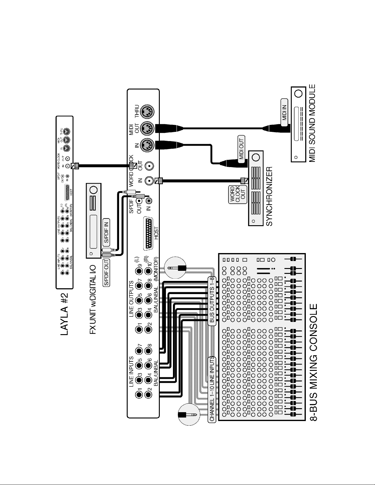
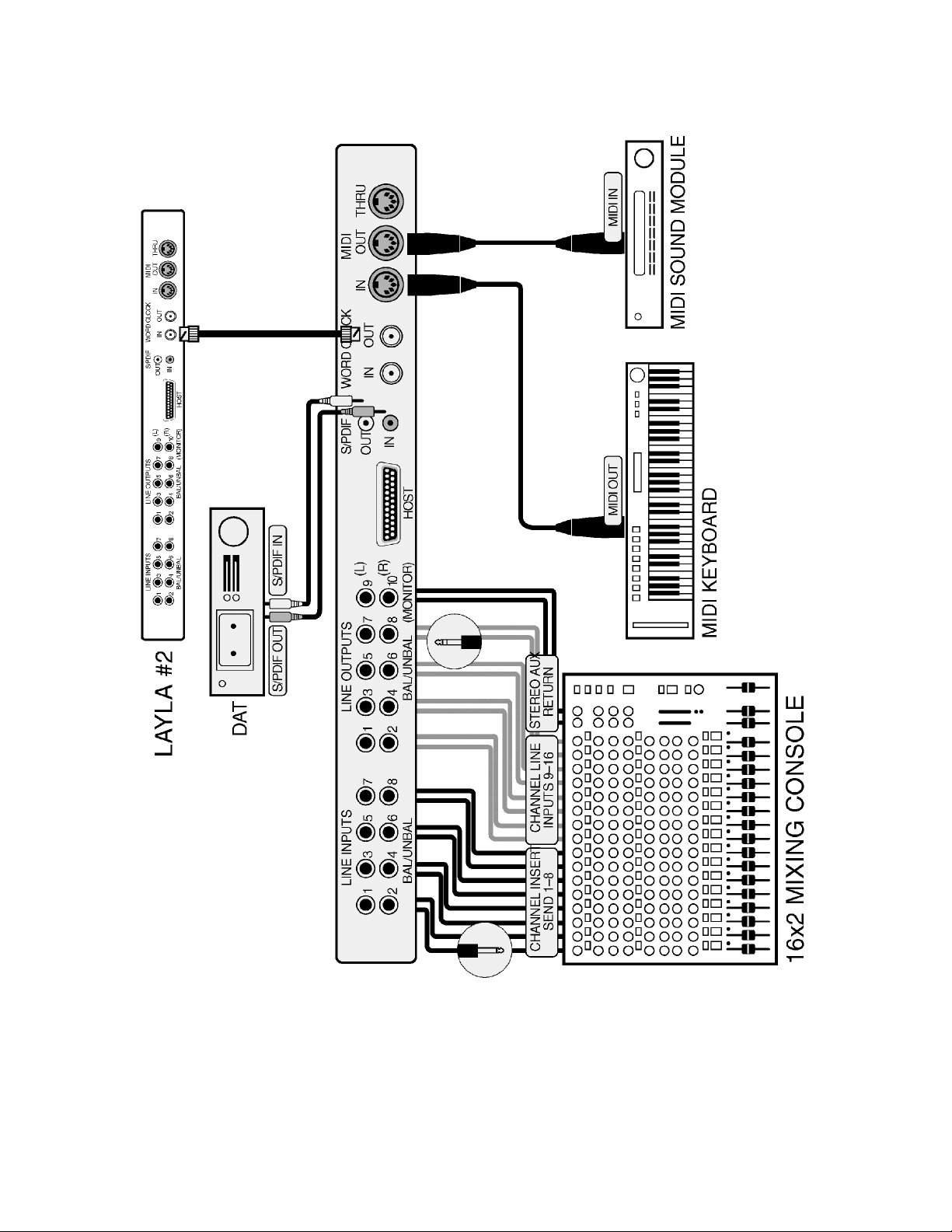
The diagrams on the following two pages illustrate sample configurations
using Layla and external audio equipment:
19
Page 20
20
Page 21

Installing the Layla Software Drivers
Now that you have completed the hardware installation, you need to install
the software drivers that allow Layla to interact properly with Windows
95/98 and your audio recording application.
Turn on the power to your computer’s CPU. After Windows 95/98 starts up,
it will automatically sense the newly installed Layla card and indicate, via a
pop-up Install Wizard window, that new hardware has been found. At this
point, you should insert the Layla CD-ROM disc.
If you are using the original Windows 95:
Within the Install Wizard window are several options. Select the option
Driver from disk provided by hardware manufacturer
. The computer
will now prompt you for the location of the driver files. These files are
located in the root directory of the Layla CD-ROM. Click the
button in the Install Wizard; this will cause the
window to appear. In the field labeled
enter the path
D:\
(depending on your system configuration, your CD-ROM
“Copy manufacturer’s files from:”,
drive may use a letter other than “D”). Click on
“Install From Disk”
OK
to complete the
Browse
installation. Now turn to page 22.
If you are using Windows 95 OSR2:
After you have inserted the Layla CD-ROM disc and clicked
next
, you’ll
see the message, “Windows found the following updated driver for this
device, Layla by Echo.” Click on the
Finish
button and Windows will
attempt to locate the drivers on a disk labeled “Echo Install Disk.”
Unfortunately, no such disk exists. So what you’ll see is a not-so-nice error
message marked with a big red X. Ignore Windows’ rude behavior and click
on the OK button. This will bring you to the
Within the window is a field labeled
Copy Files From:
Copying Files . . .
into which you’ll
window.
need to enter the path name for the Layla drivers. Type in the letter name of
your CD-ROM drive followed by :\ (for example,
D:\
). Click on
OK
, and
Windows will complete the driver installation routine. Now turn to page 22.
21
Page 22

If you are using Windows 98:
After you have inserted the Layla CD-ROM disc and clicked
next
, you’ll
see the message, “What do you want Windows to do?” Below that are two
radio buttons. If it isn’t already selected, select the one labeled “Search for
the best driver for your device (Recommended)”. Click on the
Next
button
and a dialog will appear with several check boxes indicating places where
Windows will look. If you are installing from a CD-ROM drive or from a
floppy disk, click on the appropriate box. Be sure all others are unchecked.
Click on the
disk and show you the
installation.
Next
button and Windows will locate the drivers on the install
Copying Files . . .
window as it completes the driver
22
Page 23
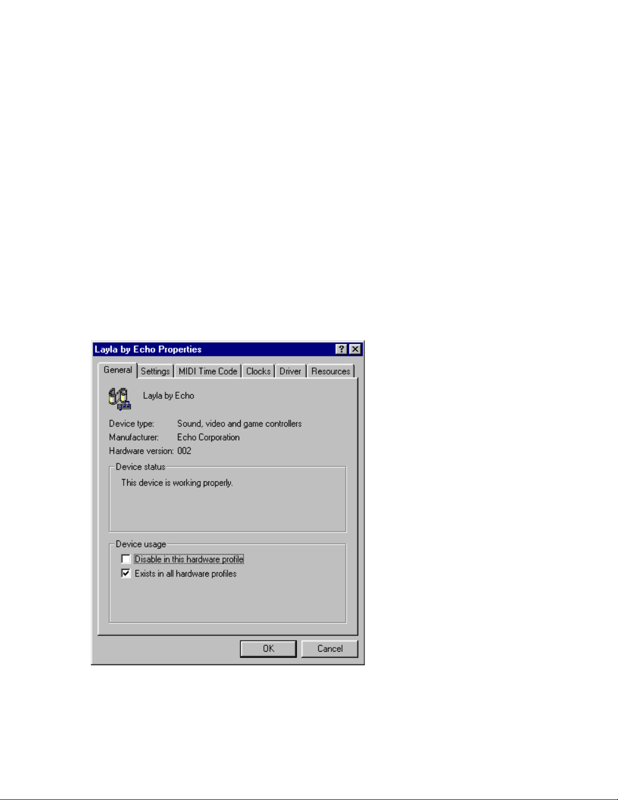
After the drivers are installed, you should verify that Windows recognizes
them. You can do this by checking in the Windows Control Panel as
follows:
Begin by clicking on the Windows
followed by
At the top of the
Manager
Game Controllers
Control Panel
System
. Now double-click on the icon labeled
window, you will see a tab labeled
; click on the tab. Now locate the line labeled
. Double-clicking on the “+” to the left of the line’s
Start
associated icon should reveal the line
button. Then select
Layla by Echo
; double-click on that
Sound, Video, and
Settings
Device
,
System
.
line. The “Holy Grail” that we’re searching for is a message that, if
everything is in working order, should now appear on your screen. In the
center of the Layla Properties window will be a section called “Device
Status.” Look for a message that reads “This device is working properly.” If
you see it, give yourself a hearty pat on the back for a job well done!
Proper installation of the Layla drivers will result in the
message, “The device is working properly.”
23
Page 24

If the message does not appear, check Appendices A, B and C for help in
isolating the cause of your difficulties.
You can now exit back to the
audio input and output devices that are available. In the
window, locate the
bring the multimedia
Multimedia
Properties
to see a list of available playback and recording devices in the
Device
fields.
Control Panel
window to check the Layla
Control Panel
icon and double-click on it. This will
window into view. Select the
Audio
Preferred
Layla Audio Input & Output Devices
The Layla driver installs into your computer as a series of stereo .WAV
devices. Pulling down the
Panels/Multimedia/Audio Playback
Preferred Device
section will reveal the available Layla
devices. You will be able to select from:
Layla 1/2 Analog Playback
Layla 3/4 Analog Playback
Layla 5/6 Analog Playback
Layla 7/8 Analog Playback
Layla 9/10 Analog Playback
Layla S/PDIF Playback
In the
Recording
section, the following choices will be available:
Layla 1/2 Analog Record
Layla 3/4 Analog Record
Layla 5/6 Analog Record
Layla 7/8 Analog Record
Layla S/PDIF Record
menu in the
Control
tab
24
Page 25
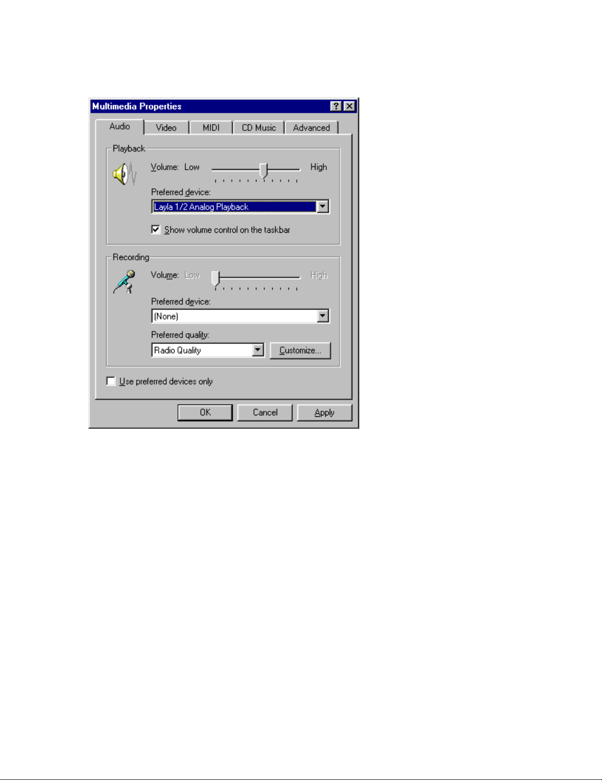
You can view the Layla input and output devices in
the Multimedia Properties/Audio window
.
You’ll find these same input and output options available when using your
audio record/editing software, with the devices assignable on a per-track
basis. See your software owner’s manual for details on how to make these
device assignments. Instructions for making these assignments in Cool Edit
Pro
Special Edition can be found on page 44 of this manual.
This completes the installation of the Layla hardware and software.
25
Page 26
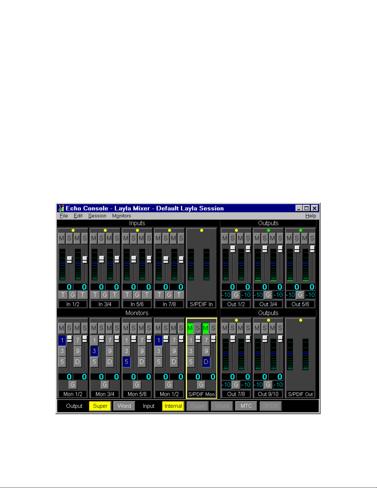
The Echo Console
Included with your Layla is a “virtual control surface” application called
The Echo Console. The Console allows you to control the audio I/O and
clocking functions of Layla, and it brings these controls to a single easy-touse location. From the console you can control input and output levels,
select synchronization clocks, adjust input monitoring, and activate the
EasyTrim
The Echo Console software was automatically installed at the same time
that you installed the Layla drivers for Windows 95/98. If installation was
successful, you should see a capital letter L in your Windows ‘95/98 taskbar
(typically in the bottom right-hand corner of your screen). Clicking on the
“L” will activate the console program. It should look like this:
automatic input gain adjustment circuitry.
26
Page 27

The console functions are grouped into three areas: inputs (in the upper left
corner), monitors (directly below the inputs that are being monitored), and
outputs (on the right hand side). The controls for a particular function/stereo
pair are then further grouped into a box that contains selection buttons, a
slider, and other controls and displays as determined by the function.
The File Menu
At the top left of the Console window you will find the
selecting the File menu, several configuration options become available to
you. The first menu option is “
New Console”
. The
allows you to create an additional iteration of the console program. In this
way, multiple devices (Laylas, Ginas or Darlas) may be controlled using
their own dedicated console.
The second option under the File menu is “
Exit”
which closes the current
instance of the console.
File
menu. By
New Console
option
The Edit Menu
“Appearance”
The
look of your console. You can change the color of each of the console
elements, change the fonts used, or choose to abbreviate labels. You may
even want to produce multiple color schemes to help recognize the device
that is being controlled. A number of preset color schemes are included.
The second option on the Edit menu is
produces the following window:
option, first on the Edit menu, lets you customize the
“Input Levels.”
This option
27
Page 28
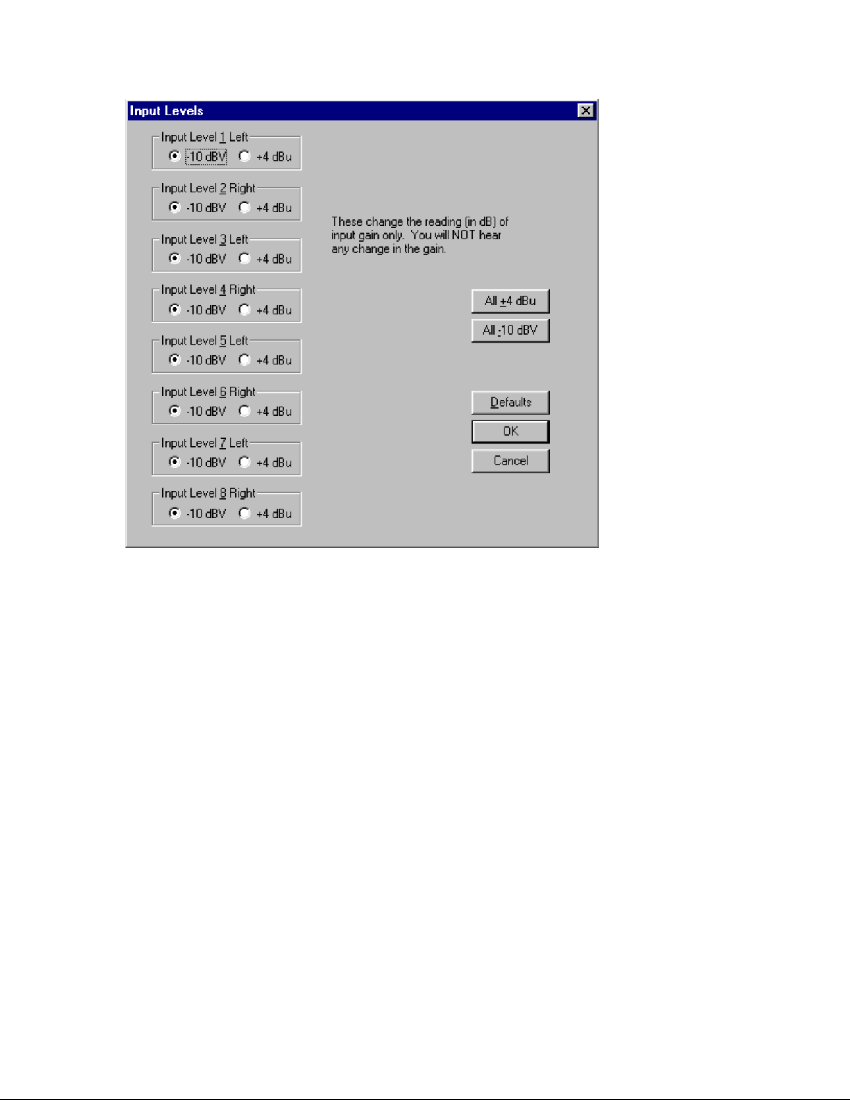
Input Levels
The
window lets you choose the gain level for each of the
analog inputs on Layla. In this way devices with differing nominal operating
levels are easily accommodated, and their input gain levels properly
displayed on the Echo Console.
The third option under the Edit menu is “
Mixer Device.”
Mixer Device
The
option lets you choose the device that the current iteration of the Console
program controls. So, if you have more than one device (Layla, Gina or
Darla) attached to your system, you can use the same console to control
them all using the
Mixer Device
option to control which device is currently
selected.
The Session Menu
Users now have the ability to save and restore any number of different
console states. A console state contains the state of each user-selectable
console setting excluding color scheme and font.
28
Page 29
“Open”
The
option, first on the Session menu, lets you open a previously
saved session.
“Save”
The
option, second on the Session menu, lets you save any changes
made to the current session.
“Save As..”
The
option, third on the Session menu, lets you save any
changes made to the current session under a different name.
“Delete..”
The
option, fourth on the Session menu, lets you delete any
session.
“Select Default Settings”
The
option, fifth on the Session menu, lets you
change to default session settings. This is not the same as opening the
default session! Rather it is a set of pre-defined settings.
“Auto Save Default Session”
The
option, sixth on the Session menu,
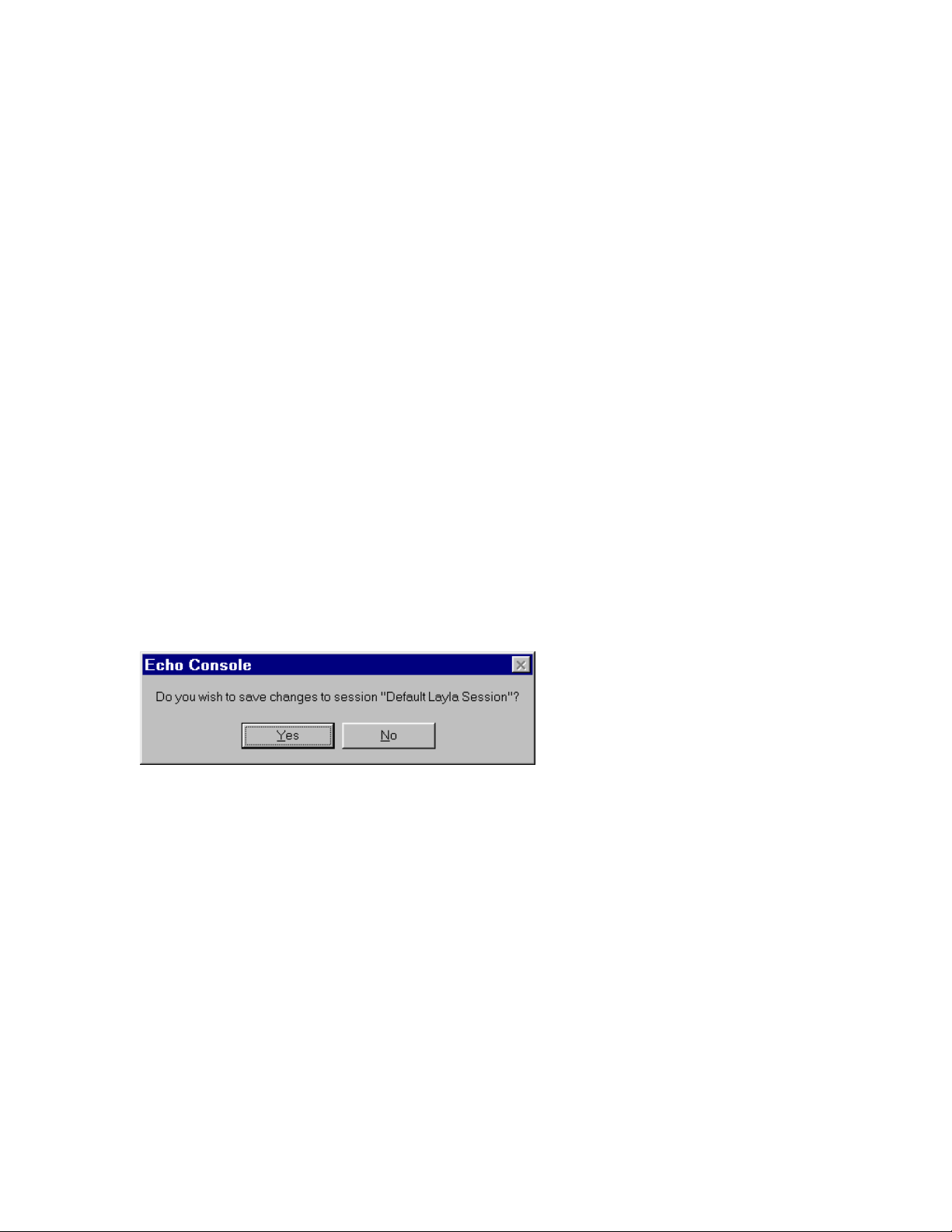
automatically saves any changes made to the default session whenever the
console is closed or a new session opened without prompting the user with:
This option insures that any changes you make to the default session will
never be lost. When a check appears on this menu item, the feature is
enabled.
The last option on the Session menu is a list of the last sessions opened.
You can quickly open a previous session by simply clicking on its name in
the list. For those who like using the keyboard, pressing the corresponding
number (displayed with an underline before the session name) also works.
29
Page 30
The Monitors Menu
“Group Mode”
The
group mode on and off. See the
option, first on the Monitors menu, lets you toggle
Monitor Controls
section below for a
description of how this feature works.
“In-Line”
The
option, second on the Monitors menu, cascades the monitors
so there is a one to one correspondence between input and output channels.
In other words, input channel 1/2 is monitored by output channel 1/2, input
channel 3/4 is monitored by output channel 3/4, etc. See the
Controls
section below for a complete description of how the monitor
Monitor
feature works.
Console Controls
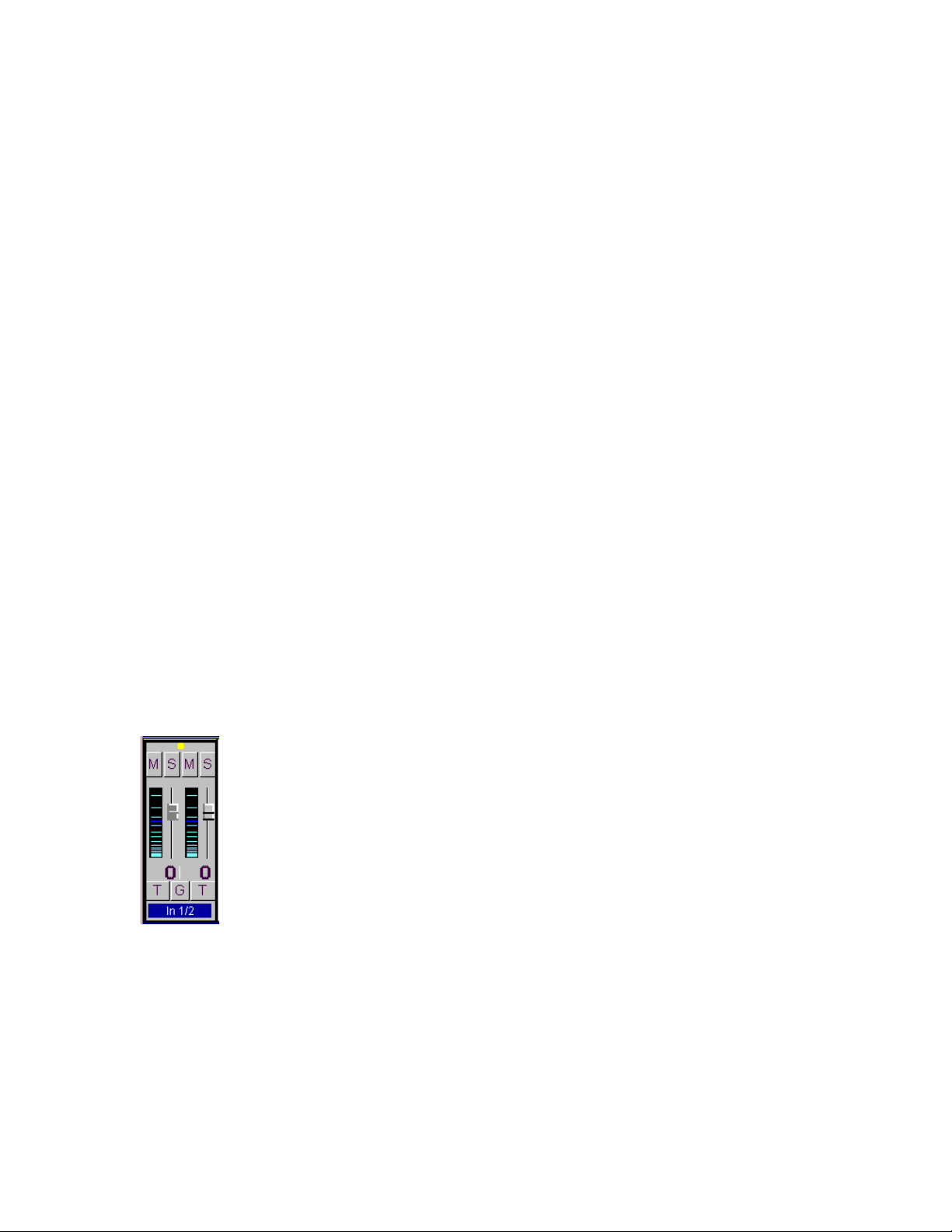
Let’s take a look at the control surface. The input controls are located in the
upper left portion of the console surface. In the center of each input control
is a pair of sliders for input gain attenuation. You will also find a pair of
level meters. Below each meter/slider pair is a display that shows the
currently selected level of attenuation or gain. One note about this display:
You will notice that the colors used to draw the gain display vary depending
on the input levels that are selected from the
from the
Edit
menu.
Input Levels
selection window
Above the meters are buttons that allow you to selectively mute (M) or solo
(S) each channel. The “LED” at the top of each input control is a button as
well. It is used to enable (green) or disable (yellow) the level meter for this
channel pair. At the bottom of the control you may choose to “gang” the
sliders (G). Ganging the sliders ties them together so that they will maintain
30
Page 31

their relative placement with regard to each other. You can also activate the
EasyTrim function (T).
EasyTrim
Automatic Input Gain Adjustment Circuitry
EasyTrim is a feature that monitors the peak level of the input signal and
automatically adjusts the input gain for maximum performance, i.e., the
point that offers the greatest signal-to-noise ratio for the material being
recorded. This allows you to take full advantage of Layla’s 20-bit dynamic
range, as it eliminates the need to leave a few dB of extra headroom, “just in
case”, while recording.
To enable EasyTrim, simply push the desired input channel’s EasyTrim
button (labeled “T” on the console). Now begin playing the material you
plan to record. In order for the EasyTrim function to work properly, it is
important that you play the loudest material you will be recording on that
channel. EasyTrim is going to optimize the input level based on the loudest
signal detected during this monitoring process. If you exceed that level
during the actual recording process, you could introduce clipping distortion.
Note that while you have EasyTrim enabled, the volume
level for the enabled channel(s) is significantly reduced.
This is a normal function of EasyTrim, allowing this
feature enough headroom to accommodate a wide variety
of input levels. When EasyTrim is deactivated, the volume
level(s) will return to normal.
Once you have played the loudest passage, deselect the EasyTrim button to
exit the EasyTrim modethe slider will jump to the correct input gain
position. Layla is now set to provide the widest possible dynamic range for
the material you will be recording. It is recommended that you repeat the
EasyTrim level-setting process for each successive track you plan on
recording. That way you can always be assured of getting the maximum
dynamic range out of your Layla system.
31
Page 32
Monitor Controls
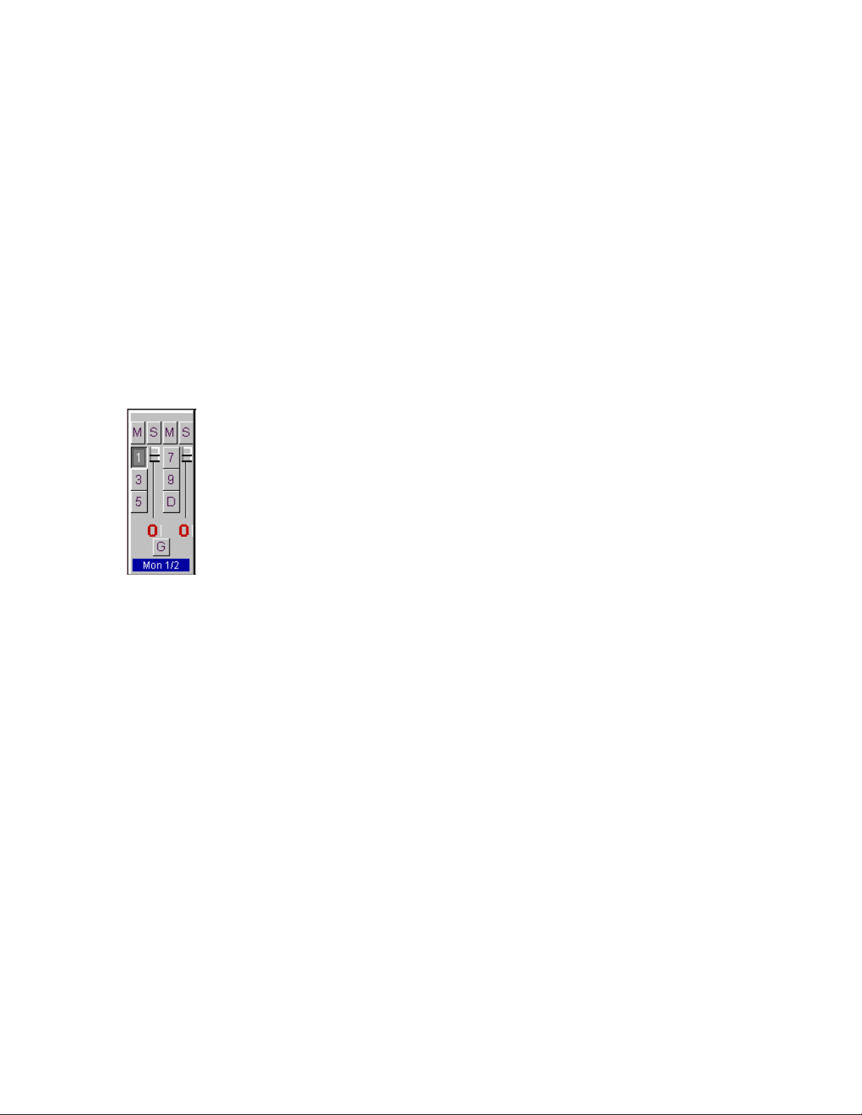
Below the input channels are the input monitor controls. The input monitor
controls allow you to monitor the record input signal via any of the
available outputs on your Layla. Each input channel pair has a
corresponding monitor output pair directly below it on the console. The
monitor controls look similar to the controls for input. The same mute and
solo buttons are found at the top, and the gang selection button is at the
bottom. In addition, a pair of slider controls is available for setting the
levels of the monitor signals. Instead of level meters, the monitor control
has a series of numbered buttons. These buttons allow you to select which
output channel pair controls are displayed, so you can adjust them.
The monitors are one of the most powerful functions of the console. When
you are recording, these controls allow you to set the level at which each
input signal will be monitored at each of the outputs, independent of the
main output level control.
When setting a monitor level, you must first select the input that will be
monitored, and then select the output for which you will set the monitor
level. Selection of the input is really just a matter of using the correct
monitor control box. A monitor setting will always affect the input pair that
is directly above it. To set the monitor for inputs 3/4, for example, simply
go to the monitor control directly below inputs 3/4 and click on one of the
six buttons found in the center of the control.
Let’s say you want to set the level at which input pair 1/2 is monitored for
each of the five stereo analog output pairs on Layla. You would first find
the monitor control that corresponds to inputs 1/2 (the control on the far left,
directly below the input control for channels 1/2). Clicking on the button
32
Page 33

within this box labeled “1/2” causes the control box to display the currently
selected levels at which inputs 1/2 are being monitored at outputs 1/2.
Clicking on the button labeled “3/4” would cause the control box to display
the currently selected levels at which inputs 1/2 were being monitored at
outputs 3/4. You can move through the remaining buttons, setting the level
at which inputs 1/2 are monitored at each of the six output pairs. The
console program remembers any settings that you make, and all settings for
all outputs are maintained independently.
In the “
Monitors - Group Mode
” menu, you can select the group mode
function which lets you easily move through the output pairs on Layla,
building the monitor mix that you want for each output. Let’s say you have
five musicians, each one listening to their own discrete output pair.
Clicking “Group Mode,” then clicking on output button “1/2” on any of the
monitor panels would cause all of the monitor controls to become active for
outputs 1/2. You could make adjustments for each input pair as necessary.
Clicking on “3/4” in any of the panels would then switch all of the monitor
controls to the levels for output pair 3/4, so you could set the levels for the
next musician, and so on.
Remember that all of the inputs are continuously monitored by all of the
outputs at some level. The degree of attenuation (or muting) of that level is
set by the monitor controls. The console program constantly maintains a
level setting for each of the 60 monitor paths it controls. Clicking on an
output selection button simply selects the settings that are displayed.
Output Controls
The right hand side of the console is dedicated to the controls for output
channels one through ten (an output meter is included for the two S/PDIF
output channels, but these levels are not adjustable). Here again, the
available controls mirror those found on the input controls: (Gang, Mute,
Solo, meter on/off, etc.)
33
Page 34
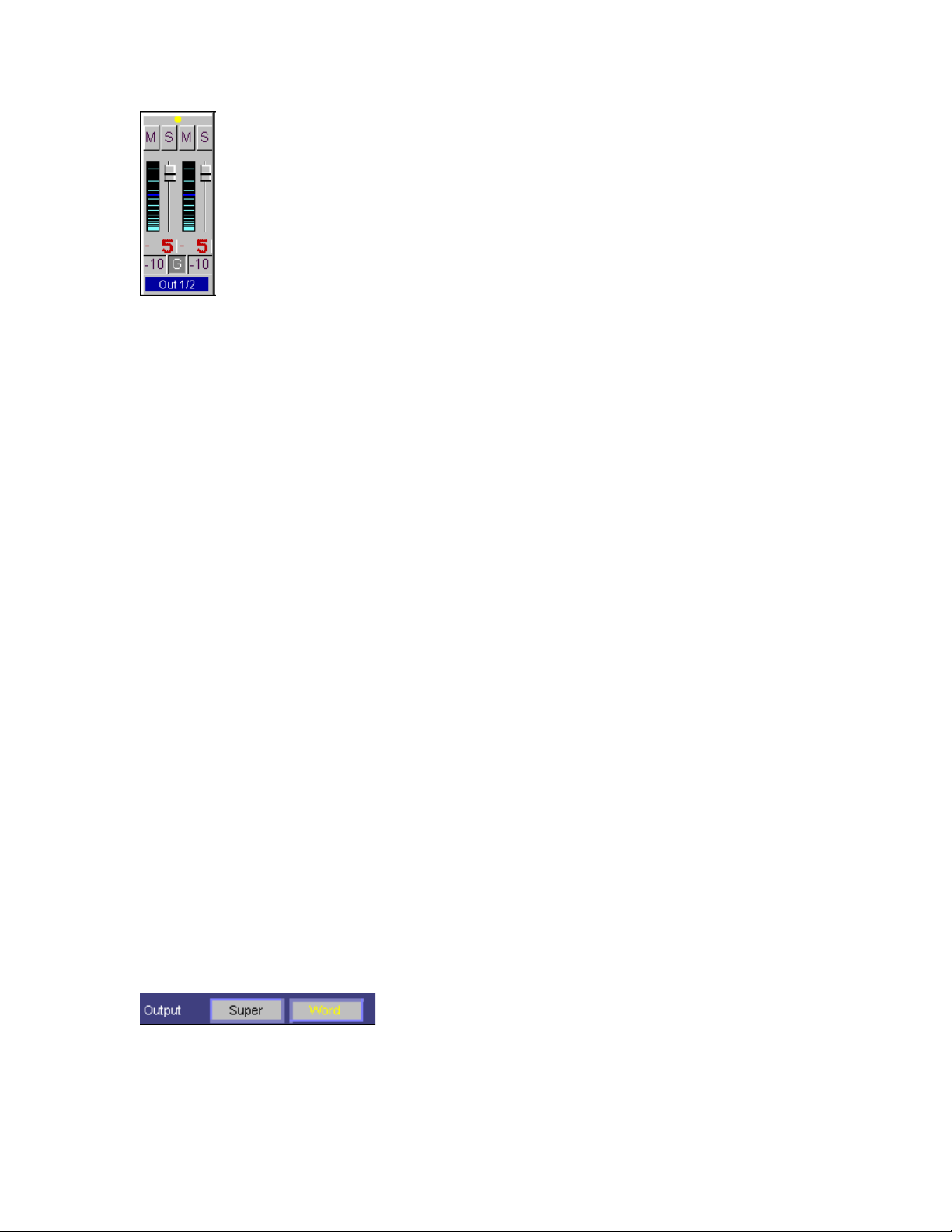
Where the EasyTrim buttons are located on the input controls, you will
instead find buttons that allow you to select each channel’s output level
(much as you can set input levels from the File menu option described
above). These buttons toggle Layla’s outputs between +4dBu and –10dBV
levels. These toggles should be set to the level that is appropriate for the
devices that are being connected to the Layla output channels.
Adjusting Record and Playback Levels
Layla’s output volume adjustments are made in the digital domain. When
you lower a volume slider, you are actually decreasing the number of
available bits, thereby taking away from the potential dynamic range of the
system. To avoid this, we suggest that whenever possible you leave the
output sliders set to their maximum positions, and perform any necessary
attenuation on your external mixer. When the Layla playback volume
controls are set to maximum and the input signal approaches the maximum
pre-clipping level, you can achieve the full 20-bit dynamic range of the
system.
Setting Clock Sources and Destinations
At the very bottom of the Console there are buttons that allow you to select
the synchronization clocks that are used by Layla. The console program will
sense which input clocking options are available, and automatically disable
those that are unavailable. On the left are the output clock options.
Here you can select from standard word clock or super clock (word clock x
256) output. To the right of the output clock selections are the input clock
34
Page 35

options. Depending on what external devices you have connected to Layla,
you may have as many as five options here.
If you are unsure which clock synchronization selections are appropriate for
your installation, be sure to read the next section, which deals with the types
of clocks that Layla supports.
Synchronizing Multiple Devices
Layla is designed to work alongside other audio equipment within a
complete Windows system. If you are planning on using Layla with other
audio equipment, please note the following:
The Layla Windows drivers (echogals.drv and echogals.inf) included in this
package supports multiple Laylas within the same system. In addition, your
new Layla will operate with Gina and Darla. Layla can also peacefully
coexist with audio equipment from other manufacturers, but be aware that
operating
alongside
order for accurate synchronization to occur, the other audio product(s) in
your system must support a synchronization mode (word clock, super clock,
etc.) that is compatible with Layla. Without such synchronization, the
individual pieces of equipment will act independently of each other. This
scenario may be fine for some musical applications; however, it is not
appropriate for situations where sample-accurate synchronization is
required.
For this reason, Layla supports many synchronization modes. Layla can
slave to word clock, super clock, S/PDIF, and MIDI Time Code (MTC). In
addition, Layla can also generate these synchronization signals, as well as
perform translation of one clock to another, such as transmitting super clock
while reading MTC.
Let’s take a brief look at the various synchronization types.
Word Clock –
connector labeled
clock runs at the selected sample rate. Think of it as a kind of electronic
another product is not the same as operating
with
it. In
This is a synchronization signal that connects to the BNC
Word Clock
on Layla’s back panel. This synchronization
35
Page 36
metronome, which can click back and forth at speeds surpassing 48,000
times a second. It is one of the most widely used forms of synchronization
in digital audio.
Super clock
– This signal comes from Layla’s
Word Clock
connector too.
Its signal runs at 256 times the sample rate. A lot of equipment, including
Layla, uses a 256x word clock internally. Using super clock allows the
equipment to synchronize more accurately and adjust more rapidly to
different sample rates.
Note
: A lot of equipment, including many “clock synchronizers”, generate
super clock using a “phase lock loop” or PLL circuit. This can produce a
super clock with a lot of “jitter,” which can cause noise on Layla’s (and
other) analog converters. Layla has a “low-jitter” clock generated using
digital synthesis techniques. It is recommended that word clock be used
when slaving Layla to other external equipment, reserving super clock for
synchronizing multiple Laylas together.
S/PDIF
– The Sony/Phillips Digital Interchange Format is a serial bitstream that has a clock signal embedded in the data stream. When recording
from a S/PDIF source, Layla will utilize the synchronization clock that is
embedded in the S/PDIF while it decodes the bitstream.
Note:
When recording from an S/PDIF port, you must select S/PDIF as the
input clock. For greater flexibility, this is not done automatically. If you
find that your S/PDIF recordings contain pops or skips, be sure that you
have selected S/PDIF as your input clock.
MIDI Time Code (MTC)
– MIDI time code differs from the preceding
synchronization methods. Instead of simply providing the rate at which
things should proceed, it transfers information in an elapsed time format
(HH:MM:SS.) In addition, MTC also transmits a frame number to give the
fine definition that is needed. This longitudinal format has the benefit of
including positional information; however, over time it tends not to
maintain as tight a sync as sample based synchronization techniques.
Now let’s take a look at some possible configurations and how you might
set them up from a synchronization standpoint.
36
Page 37

Let’s start simple. Suppose that Layla is the only audio device used in your
system. Since you have no other devices to synchronize with, simply select
“Internal” for Layla’s input clock. Layla will then use its own clock to
control its operation.
Now a little more complicated set-up: You have two Laylas connected.
Simply set Layla #1 to “Internal” for its input clock and super clock for
output. Now connect the first Layla to the second one via a BNC cable
running from Word Clock Out on Layla #1 to Word Clock In on Layla #2.
Now select super clock for Layla #2’s input synch. Your Laylas will now
operate in unison.
No matter how many devices you are synchronizing, the concept is
essentially the same. You are merely “daisy-chaining” devices together
using compatible clocks. One device will operate as the source of the master
clock, with each successive device using that clock to sync.
Console Keyboard and Mouse Shortcuts
To navigate between control groups:
Ctrl + Tab
Ctrl + Shift + Tab
To navigate between controls within a control group:
Tab
Move to next control.
Shift + Tab
Ctrl + S
Ctrl + M
Ctrl + A
Ctrl + T
Ctrl + G
Enter
Toggles the state of any selected control.
To control volume sliders:
Right mouse click
Ctrl + left mouse click
Ctrl +
Raise volume of selected control about 1 dB.
↑↑↑↑
↑↑↑↑
Move to next control group.
Move to previous control group.
Move to previous control.
Toggles between left & right Solo buttons.
Toggles between left & right Mute buttons.
Toggles between left & right Trim buttons.
Toggles between left & right +10/-4 buttons.
Select the Gang button.
Allows user to type in the desired level.
Set volume level to zero.
Raise volume of selected control about 5 dB.
37
Page 38

Ctrl + Alt +
Ctrl +
Lower volume of selected control about 1 dB.
↓↓↓↓
Lower volume of selected control about 5 dB.
↓↓↓↓
Ctrl + Alt +
Raise volume of selected control about 0.004 dB.
↑↑↑↑
Lower volume of selected control about 0.004 dB.
↓↓↓↓
Individual channel titles are customizable. To change the text of a channel
title (i.e., In 1/2, Mon 3/4, Out 5/6, etc.),
right mouse click
on the channel
title and type in the desired text.
Additional Configuration Settings
In addition to those settings that can be made using the Console program,
there are a number of other configuration options you can access. These are
found on the Windows Control Panel. To access these controls, begin by
pressing the Windows
Start
button. Select
the Control Panel window, locate the icon for
it. Click on the tab titled
Sound, video and game controllers
Echo
, and double-click. This will bring up the Layla Properties window,
Device Manager
. Finally, locate the line titled
which we saw briefly at the conclusion of Layla installation.
We have previously seen the “General” screen, so let’s move on to the
“Settings” screen by clicking on the tab labeled
Settings
System
, then
Control Panel
, and double-click on
. Now locate the line titled
Layla by
Settings
.
. In
38
Page 39
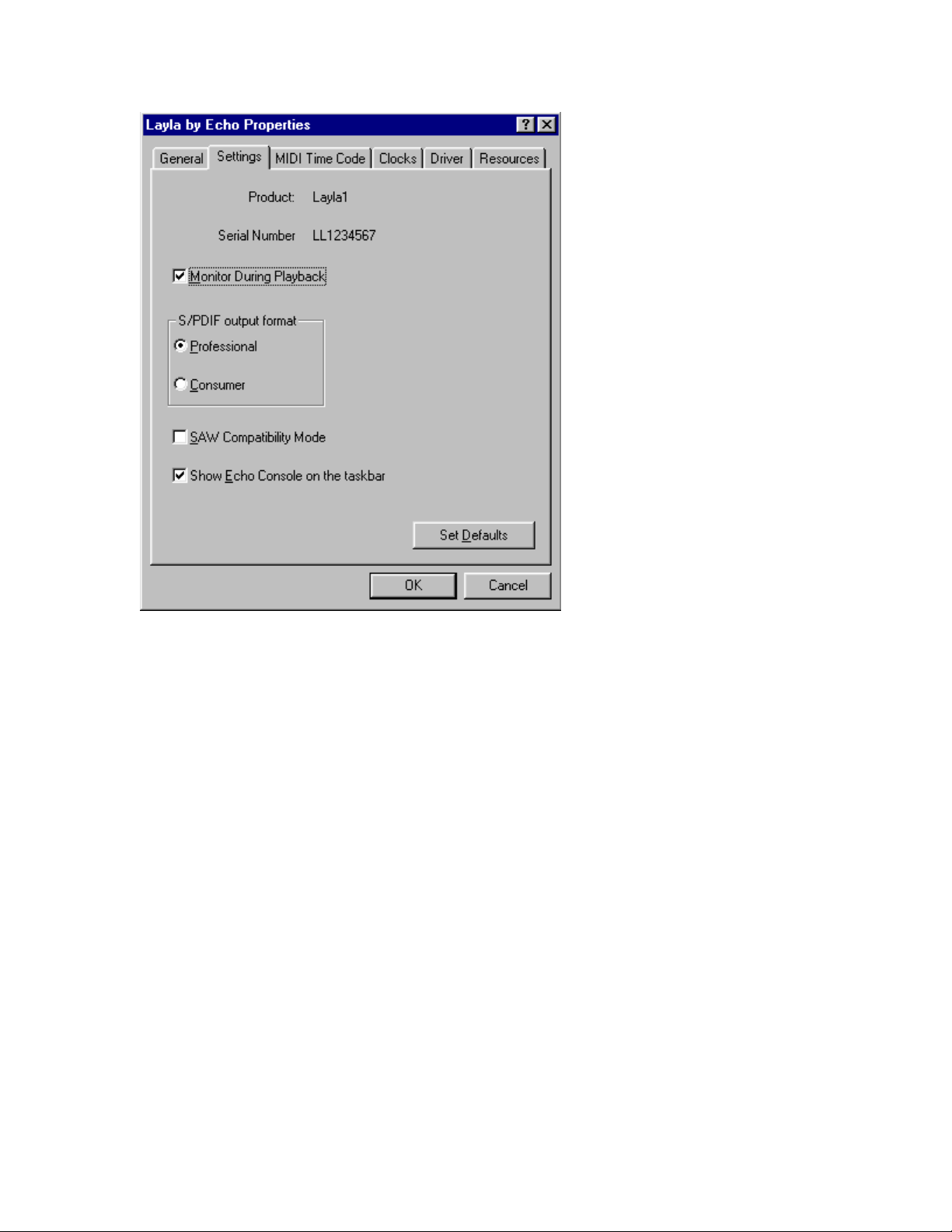
The “Monitor During Playback” Control
In the default mode, Layla allows you to monitor your input signal whether
you are recording, playing back, or simply idle. In some situations, such as
when performing punch-in recording, it may be desirable to have the input
signal muted until Record is enabled. In the
appears you’ll see a checkbox labeled
Monitor During Playback
Layla Properties
window that
. Uncheck
the box to disable input monitoring; recheck it to once again enable input
monitoring. Monitoring controls are also available on the Echo Console.
Selecting the S/PDIF Output Mode
Layla can transmit digital information in either of two modes,
“professional” or “consumer.” The primary difference between the two is in
the implementation of the SCMS copy-protection bit, which, in the
consumer format, prevents the user from making digital copies of a digital
copy.
39
Page 40

Layla’s S/PDIF output defaults to the Professional mode. If you are
recording from Layla into a consumer DAT deck, the deck may not be able
to recognize the signal until you switch Layla’s output to Consumer mode.
We have provided a software switch in the Layla driver that allows you to
select which mode Layla transmits. In the window that appears you’ll see a
pair of check boxes in an area labeled
labeled
Consumer
and the other
S/PDIF Output
Professional
Setting: one box is
. Select the appropriate
mode for your DAT (if you don’t know which one to use and are having
difficulties, simply try the one that is not currently checked).
Important note: Layla never transmits the SCMS bit, regardless of which
mode is selected.
SAW Compatibility Mode
When using Layla with the Software Audio Workshop (SAW) program
from Innovative Quality Software, there are some special considerations
that must be accommodated by the Layla driver. SAW expects an equal
number of inputs and outputs on Layla. For SAW compatibility, the driver
creates a non-functional mirror of input channels 7 and 8 (making an equal
number of ins and outs). To insure that Layla will operate properly with
SAW, check the box labeled
option should
be checked when Layla is being used with the SAW
only
SAW Compatibility Mode
. (Note: This
application.)
Show Echo Console on the Taskbar
The last selection on the
the Echo Console program will occupy a space on the Windows taskbar (the
“L” in the bottom right-hand corner of the Windows desktop).
Settings
screen allows you to determine whether
Checking this option enables this feature, unchecking it disables it.
40
Page 41
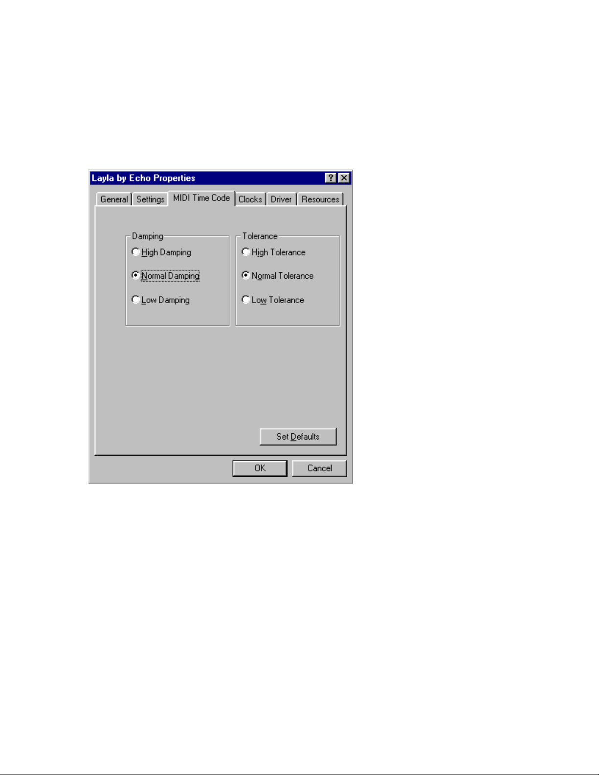
MIDI Time Code Settings
Now let’s take a look at settings that affect performance reading MTC.
Click on the tab labeled MIDI Time Code. The Properties window should
now look like this:
Because of the somewhat coarse resolution of MIDI Time Code, and its
ability to exhibit “wow and flutter” (fluctuations in timing and consistency),
the sync signal may sometimes stray from optimal. The Layla driver will
automatically correct for these inconsistencies. When and how these
corrections are made is configurable.
Tolerance
The
setting lets you select how far you want to allow the
synchronization to stray before a correction is made. Many times, if left
alone, the sync may correct itself by first straying in one direction and then
going back the other way. If the tolerance is set too low, Layla will correct
the synchronization too frequently. This produces frequent jumps to correct
the clock, introducing jitter. If the tolerance is too high, the synchronization
41
Page 42

will shift too far before a correction is made, which will also yield
unsatisfactory results.
Damping
The
setting lets you configure how quickly the corrections
described above take place. Once Layla has determined that a correction is
needed, a low damping level will effect the correction rapidly. A high level
of damping causes the correction to occur in a more gradual nature.
If you feel that a change is needed in the defaults for these settings because
of poor MTC synchronization, it is generally wise to adjust the
setting first. Use the
satisfactory results with the
Damping
Tolerance
adjustment if you are unable to obtain
setting.
Tolerance
42
Page 43
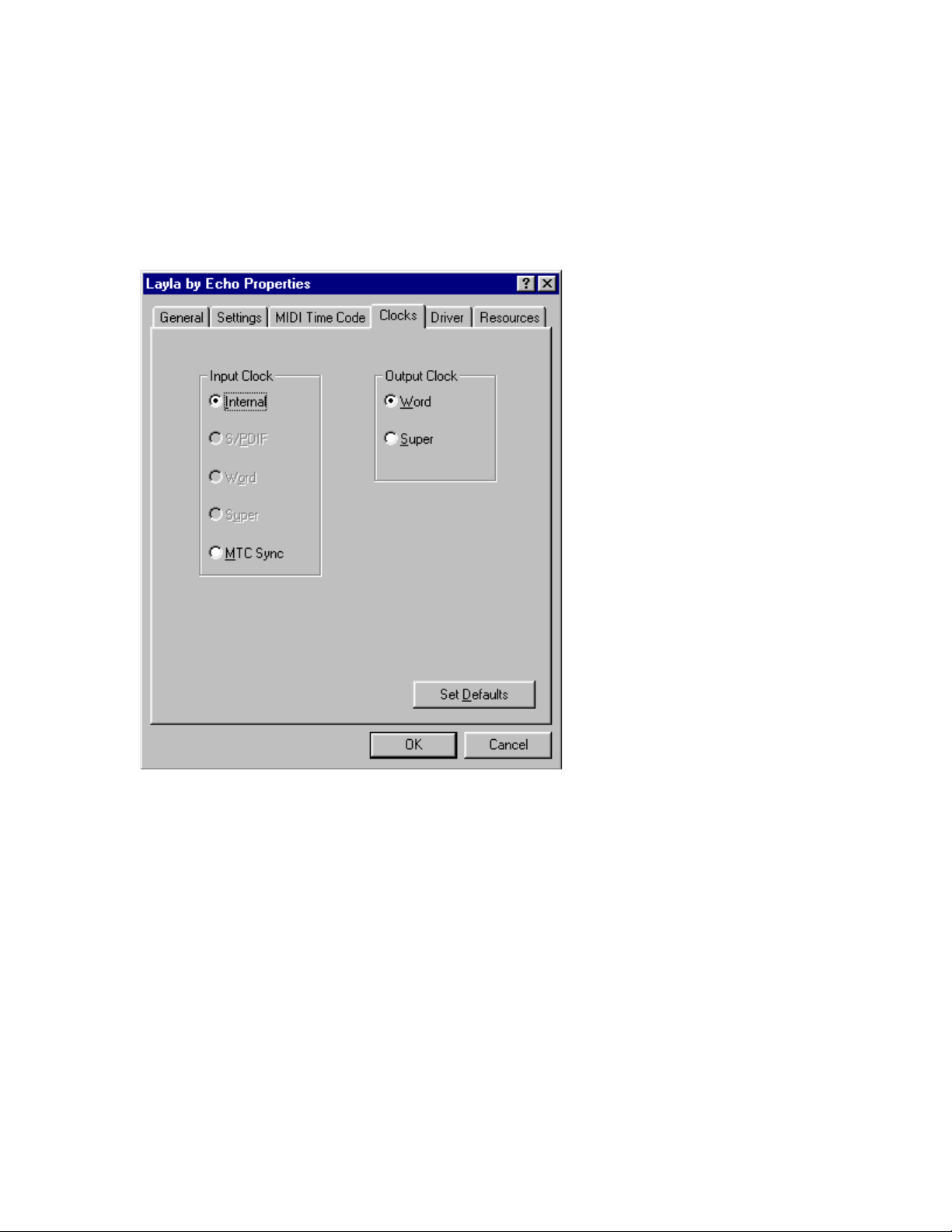
The Clocks Settings
Although you can set the synchronization clocks from the Echo Console,
these settings are also available from the Layla Properties menu. Click on
Clocks
the
tab. The window will change to look like this:
Only those clock sources that Layla determines to be available will be
enabled for selection.
ASIO Driver Installation
The ASIO driver is automatically installed on your system at the same time
the Echo Layla/Gina/Darla driver is installed. To use it:
1. If you already own a copy of Steinbergs’ VST program, skip to step 3.
2. On the installation CD, run the program:
\Audio Software Demos\Steinberg\CubaseVST demo\VSTdemo.exe
43
Page 44

which will install a fully functional demo of this program. What fully
functional means is that all of the features are in place so you can really
put the program through its paces. The only thing disabled is the ability
to save. If you want save your work, you must buy the program. That's
the way it works.
3. Start CubaseVST or CubaseVST demo
4. Go into menu
Gina/Darla/Layla
Audio - System
" option in the
. Select the "
ASIO device
ASIO Echo
combobox.
5. Click the OK button.
6. It is best to load or create a song and verify that the driver is functioning.
7. The default latency is about 187 milliseconds using an 8k buffer. This
may be changed in the dialog box found in menu
select the
ASIO Control panel
button. Choose a buffer size between 1K
Audio - System
then
and 64K. The smaller the buffer, the lower the latency. At 1K, the
latency is 25 milliseconds.
8. You can change the data and buffer sizes in the ASIO Control panel
without leaving VST provided you respond consistently to the dialog
boxes. In other words, if you change the buffer size in the ASIO Control
panel and select the Ok button, you must also press the Ok button in the
next dialog which says:
"
Change ASIO Device: All Fx and Bus Settings will be lost!
".
Choosing the Cancel button will result in no more sound until you exit
VST and restart it.
9. When using the ASIO driver with more than one card, you must be sure
they are synched using either the Word Clock (Layla only) or S/PDIF
(Layla & Gina). This involves the appropriate cabling and enabling the
clocks in the console(s). See section “
The Clocks Settings
” in this
manual for details. If you fail to do this, the driver will now display a
warning dialog. You will not be able to continue until the problem has
been corrected.
10. When running VST selecting menu
Options - Reset
pressing the Play button results in no sound. Simply press the
Devices followed by
Stop
button twice to reset the position pointer to the beginning of the buffer.
Then press Play and sound will resume.
44
Page 45

Installing Cool Edit Pro
Included with your Layla system is a special version of Syntrillium
Software’s Cool Edit Pro, a powerful multitrack audio recording and editing
application. To install the software:
1. Insert the Layla CD-ROM.
2. Press the
Browse…
labeled
drives to appear. Select your CD-ROM drive. On the CD-ROM is a
folder called Syntrillium; double-click on this directory to open it. Now
locate the file in the Syntrillium directory called SETUP. Select this
program and run it.
Start
button, and select
At the top of the window that appears, you will see a box
Look In:
. Clicking on this box will result in a list of your disk
Run…
Special Edition
from the menu. Now select
The SETUP program will copy all of the necessary files to your hard drive.
It will also add a program group called “Cool Edit Pro – Special Edition” to
Program
the
Cool Edit Pro – Special Edition comes with very thorough on-line
manual/help, so you’ll be able to get up and running with a minimum of
hassles (hopefully none at all!). We do, however, suggest that you
familiarize yourself with the items under the
the program’s Help menu.
listings available from the
Start
button menu.
Quick Reference
heading in
45
Page 46

Cool Edit Pro: Assigning Layla’s Inputs & Outputs
Layla’s inputs and outputs are assigned to tracks in two different ways,
depending on the viewstereo waveform or multitrackin which you are
working. In the stereo waveform view, select
the window that appears you can define the
Waveform Recor
d devices. Simply highlight the Layla inputs and outputs
you wish to use in the appropriate fields. These settings will apply for all
files that you play or record when in the stereo waveform view. These
device settings are saved as Cool Edit Pro preferences; as such, they will be
used for all subsequent sessions until you change them.
In the multitrack view, the inputs and outputs are assigned on a per-track
basis. Before making assignments, however, you’ll need to set up the
Preferred Multitrack Devices
. To do this, click on either of the small
numeral 1s at the far left of the track display; doing so will bring up the
Playback Device
Preferred Multitrack Devices
of
window. Click on the
. In the
Device List
analog playback devices 1/2, 3/4, 5/6, 7/8, and 9/10 into the 1
th
4
, and 5th fields, respectively. Assign the S/PDIF playback device into the
th
field. In the Record fields, assign
6
3/4, 5/6, and 7/8 to the 1
Layla S/PDIF Record
st
, 2nd, 3rd, and 4th fields respectively. Assign
into the 5
Layla Analog Record
th
field. Click
back out to the multitrack view screen. These device assignments are
saved as Cool Edit Pro preferences, and will be used each time you open a
new session.
To make the playback and record device assignments for a specific track,
click anywhere in the track’s blue-gray area at the far left of the track
display. This will open the
Playback Device
outputs
.
and
Track Info
Record Device
window. Click on the arrows in the
fields to select the desired inputs and
Options/Settings/Devices
Waveform Playback
button; you’ll see a list
Playback
fields, assign Layla
devices 1/2,
Okay
on each window to
and
st
, 2nd, 3rd,
; in
46
Page 47

Cool Edit Pro: Optimizing Multitrack Performance
Background mixingthe process Cool Edit Pro uses to allow a large
number of tracks to play simultaneouslyrequires significant processing
power from your computer. With larger sessions, your computer may
become so occupied with mixing that you experience audio dropouts in
multitrack playback. This will usually happen because the background
mixing is not sufficiently complete (watch the
is initiated. There are a few things you can do to help remedy this; however,
be aware that you may still have to wait for a time before hitting the
button when working with very large sessions.
The settings in
Options/Settings/Multitrack
the background mixing processes. In particular, pay attention to the
Playback Buffer Size
and the
Background Mixing Priority Level
key to determining how to adjust these settings is to watch the
As a general guideline, if you notice dropouts occurring even though the
Mix Gauge
filled), try reducing the
Mixing Priority Level
seems reasonably complete (the meter is beyond ¾ of the way
Playback Buffer Size
(higher values reduce the priority level).
Conversely, if you notice dropouts and see that the
around the bottom “empty”), try increasing the
lowering the
Background Mixing Priority Level
The goal in adjusting these settings is to achieve a balance between values
large enough for the program to work properly and low enough to conserve
the computer’s resources. The
Background Mix Priority
enough (lower settings produce a higher priority) to keep the mix ahead of
playback, but not be so high as to adversely affect performance (by
consuming too much of your computer’s resources). In short, the lower you
can keep this setting while still keeping the
the better. Raising the buffer size consumes more of your computer’s
memory, so setting this too high can negatively affect performance.
When adjusting these settings, do so by small amounts, using decimal
increments/decrements. Also, note that the settings will produce different
results from session to session. As the number of tracks and the number of
Mix Gauge
) before playback
Play
play a big part in optimizing
. The
Mix Gauge
, and raising
Mix Gauge
Playback Buffer Size
the Background
is hovering
and
.
must be high
Mix Gauge
reasonably filled,
.
47
Page 48
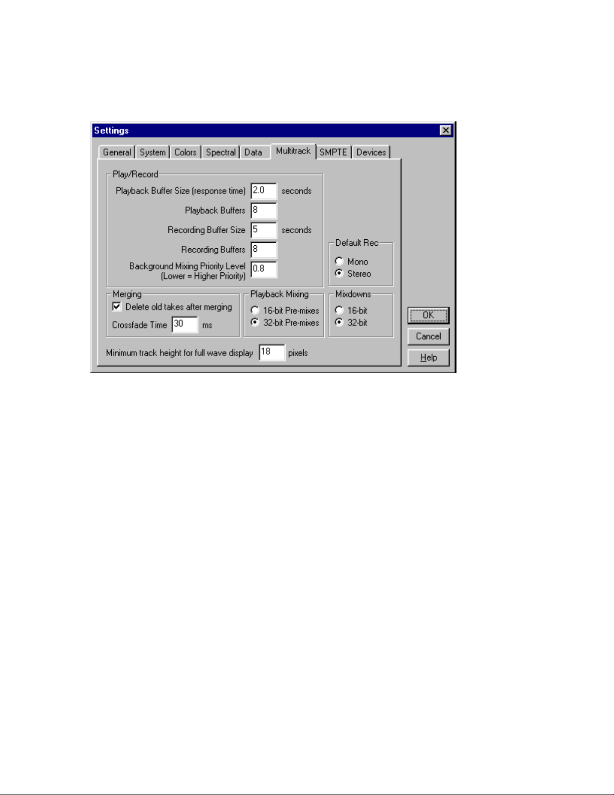
output devices vary, so may the settings you’ll need to use to maximize
performance.
Use the Multitrack Settings shown above as a starting place when
adjusting your system to optimize the performance of Cool Edit Pro.
Cool Edit Pro will take more time performing background mixing when you
have your tracks assigned to multiple sets of Layla’s outputs. In this
scenario, Cool Edit Pro creates a separate mix for each output device (each
Layla channel-pair). This additional mixing demands more processing
power from your computer, resulting in longer mix times and possible
skipping during playback. If your system is performing sluggishly, you can
temporarily assign all tracks to a single channel-pair while monitoring to
speed things up. When doing so, it is recommended that you check
Pre-mixes
mode in the
multiple output devices,
Settings/Multitrack
16-bit Pre-mixes
is the recommended mode.
screen. When monitoring to
32-bit
Note that the 16-bit and 32-bit modes are playback settings only; that is, the
data on your disk remains at the resolution at which it was recorded.
48
Page 49

Contacting Customer Service
If you experience any trouble with your Layla system please go to the
support area of our website at www.echoaudio.com
and check out the
troubleshooting FAQ’s we have there. If you can’t find a solution to your
problem there, please fill out the provided technical support email form.
This form will be sent to our technical support staff and they will respond to
you quickly.
Please fill out the form completely.
We will not respond to
you unless you fill out the form in its entirety. We cannot help you unless
you give us the required information.
We do ask you to please read through this manual and the support area of
our website before contacting us. You may find an answer to your problem
using the Appendices in the Layla owner’s manual and/or Cool Edit Pro’s
on-screen help.
Thank you for buying Layla!
Note, too, that all Cool Edit Pro Special Edition support issues are
handled solely by Echo Corporation.
Software for technical support.
Please do not call Syntrillium
If you do, they will simply refer you to
Echo Corporation for help.
49
Page 50

Appendix A: The Echo Reporter Troubleshooting Guide
After you run the Reporter program, your summary may contain one or
more of the following problem/error messages. Consult the table below for
suggestions on interpreting the messages and finding solutions.
Message...
Problem... What to do...
* The Echo line of sound
cards require Windows 95
or Windows 98
* The Echo Reporter has
found that your system does
not have a PCI BIOS. To
alleviate this problem,
please purchase a PCI
system, version 2.1 or later
* The Echo line of sound
cards requires PCI version
2.1 or later. To alleviate
this problem, please
purchase a PCI system,
version 2.1 or later.
*The Echo Reporter has
determined that your
system has no free
interrupts. The Echo line
of sound cards requires
one interrupt to be
available for use. To
alleviate this problem, try
removing unnecessary or
infrequently-used
peripheral devices
*The Echo Reporter has Your computer has no First, verify that 32-bit disk
Your computer is using a
Windows 3.xx or Windows
NT operating system
Your computer does not
have an operational PCI
Bios
Your computer has a PCI
BIOS, but it is version 2.0
or earlier
Your computer has no free
interrupts. Interrupts 0-15
are either being used or are
reserved by other
applications or drivers
The Echo Reporter and
Layla will only operate in
Windows 95 or Windows
98. You must update to one
of these operating systems.
Upgrade to a PCI computer
with BIOS version 2.1 or
higher
Upgrade to a PCI BIOS
version 2.1 or higher
There is no single direct
solution to this problem.
Generally, you will need to
free an interrupt by
eliminating a peripheral
device. Consult Appendix C
for suggestions on making
an interrupt available for
Layla
50
Page 51

found that none of the hard
drives that were tested meet
minimum performance
standards with respect to
transfer rate. Though your
system supports the Echo
line of sound cards, we
recommend that you
upgrade your hard drive(s),
as your existing drive(s) are
not capable of sustaining
the minimum transfer rates
required for reasonable
performance
*The Echo Reporter has
found that your system may
not be equipped with a
Pentium (or faster)
processor. The algorithm
we are using for processor
detection is known to return
faulty values for many of
the AMD, Cyrix, and other
non-Intel chips, so be sure
to double-check this
warning against processor
identification that your
machine displays each time
you boot up. It is essential
that your machine be
equipped with an Intel
Pentium or Pentium II
processor.
physical hard drives that test
at a transfer rate better than
500Kb/second. This will
seriously hinder the
performance of Layla and
will greatly limit the
activities that you can
perform.
Your computer appears to
have a microprocessor that
is not fast enough to
properly carry out the
necessary operations. If
your computer’s
microprocessor is
characterized as “Pentiumclass,” you may want to go
ahead and try working with
Layla to see if your results
are satisfactory.
access is enabled. This is
done under the heading
Performance
Properties
in
System
. The only other
solution is to add a faster
hard disk to your system.
The only way to fix this
problem is to upgrade your
microprocessor to an Intel
Pentium or Pentium II
processor.
51
Page 52

Appendix B: General Troubleshooting Guide
Problem:
After installing Layla, one or more of your peripheral devices no
longer functions properly.
Solution
interrupt conflict was created. Please see
Interrupt Conflicts
: During the installation of your Layla, it is possible that an
Appendix C: Resolving
for more information on this topic.
Problem
: You installed Layla and restarted Windows. Now Windows
indicates that it has found new hardware and wants you to install a driver
for it. This hardware was working perfectly well before you installed Layla
and the driver for this hardware was already installed.
Solution:
It is possible that during the installation process you moved an
existing card from one slot to another. Windows keeps track of installed
devices, not only by peripheral type, but also by physical location. In
moving a card from one slot to another, Windows will no longer recognize
the card as one for which a driver is installed. You must re-install the driver
for the card that was moved.
Problem
: You are unable to get your DAT recorder to recognize Layla’s
S/PDIF output.
Solution:
Digital information is transmitted in either of two modes,
“professional” or “consumer.” The professional mode is usually
implemented in devices that are likely to be used in professional recording
environments, whereas the consumer mode is commonly implemented on
equipment designed for home use in the consumer market. The primary
difference between the two modes is in the implementation of the SCMS
copy-protection bit, which, in the consumer format, prevents the user from
making digital copies of a digital copy. In most professional equipment, this
copy-protection bit can be turned off or on according to the user’s needs. In
consumer products, the SCMS bit is always enabled.
52
Page 53

Unfortunately there is no way for the transmitting device to automatically
detect which format the receiving device is able to accept. If you have a
DAT deck that is not able to read the S/PDIF output from Layla, chances are
Layla is transmitting in the mode that the deck is not equipped to handle.
We have provided a software switch in the Layla driver that allows you to
select which mode Layla transmits. To access this switch go to the Windows
Start
button and select
System
the
icon, and select the
small plus sign to the left of the line labeled
Controllers
line that says
. To view the settings for Layla’s driver, double-click on the
Layla by Echo
Settings
and select the tab entitled
. Select the
Control Panel
Device Manager
Sound, Video, and Game
, double-click on
tab. Now click on the
Settings
. In the
window that appears you’ll see a pair of check boxes in an area labeled
S/PDIF Output Setting
Professional
. Select the appropriate mode for your DAT (if you don’t know
; one box is labeled
Consumer
and the other
which one to use, simply select the one that is not currently checked). Now
exit from the
Control Panel
and again try recording to your DAT.
Important note: Layla never transmits the SCMS bit, regardless of which
mode is selected.
Problem:
When the Windows start-up sound plays, it plays at an altered
pitch.
Solution
: When Layla is set to sync with an external device, it will playback
at the rate generated by that device. If the startup sound you are using was
sampled at 8 kHz, but you are synchronized with a device running at
44.1 kHz, the startup sound will play back at this faster rate. You have three
choices - ignore the altered pitch, switch to Layla’s internal clock, or use a
different device for the startup sound playback. We suggest that you never
use Layla for playback of any of Windows’ system sounds.
Problem:
Layla doesn’t seem to recognize the synchronization clock to
which it is connected.
Solution
: Although it may seem obvious, the first thing to check is that
there is a physical connection between the device generating the clock and
53
Page 54

Layla’s rack mount interface. Just because multiple devices are connected to
the same computer doesn’t mean they are synchronized. Next, be sure that
you have selected the desired input clock source in the Console program, or
made the selection on the Clocks menu in the Control Panel.
Problem:
When trying to run sound editor software, such as Cool Edit or
Cubase, the program consistently hangs, and a general protection fault error
is displayed.
Solution
: We have rarely seen this problem, but in those few instances, the
installation included two or more Laylas as well as a MIDI Time piece from
Mark of the Unicorn. The problem is a limitation in the maximum number
of MIDI devices that Windows will allow to be installed and used
concurrently. Windows 95/98 places a limitation of ten such devices.
To cure your problem, you must disable those additional MIDI devices that
are being added by Layla. To do this, double-click on the “Multimedia”
icon on the Windows control panel. Now select the window titled
“Advanced”. Locate the line titled “MIDI Devices and Instruments” and
click on the small plus sign “+” to the left. You should now see the MIDI
devices that are currently installed. To disable those MIDI devices that are
added by Layla, simply double-click on a Layla MIDI device (MIDI for
Layla by Echo), then select the option “Do not use the MIDI features on this
device”. You will need to disable the MIDI functionality on any remaining
Layla MIDI devices that are installed.
Problem:
Recordings made using the S/PDIF port contain occasional pops
or skips.
Solution
: When recording with the S/PDIF port, you must manually select
the S/PDIF clock as the input clock. This can be done using the Console
program or from the Layla Properties screen in the Windows control panel.
54
Page 55

Appendix C: Resolving Interrupt Conflicts
While Plug-and-Play is often called “Plug-and-Pray,” it actually works
quite well most of the time. We estimate that 95% of Layla installations will
go without a hitchthat Plug-and-Play will properly assign resources to
your card without any conflicts. The other 5% of you will likely experience
interrupt problems caused by older, non-Plug-and-Play cards that are
installed in your system. These problems can manifest themselves by
causing your new Layla to not function properly; in some instances, devices
will fail that were previously working just fine.
If you are having problems with your computer after installing a new Layla
card (or if you are unable to successfully install the card at all), please read
the sections below describing what interrupts are, how they are assigned,
and how to work around interrupt conflicts. Hopefully, we’ll be able to help
you solve your problem without too much trouble.
What is an Interrupt?
A computer has two ways of telling when a device, such as an audio card, is
ready to exchange data with a program. One way is to have the computer
periodically ask or “poll” the device to see if it’s ready to transfer new data.
Since it is important to do the transfer as soon as it is ready, the program
must poll the card quite often, which wastes the computer’s resources.
The other method is to have the card “interrupt” the program when it is
ready to transfer data. It does this by sending a signal over one of the many
interrupt wires connected to the slot into which it is plugged. PC’s have 16
possible interrupts (0 to 15), five of which are reserved by the motherboard
for the keyboard, system timer, etc.
ISA and PCI Interrupts
There are two types of expansion connectors found on today’s computers.
The older style connectors are called ISA (for Industry Standard
Architecture) connectors. ISA connectors have 11 of the 16 PC interrupts
55
Page 56

wired to them. Older ISA cards (also called “legacy” cards) have you select
which interrupt is used by configuring jumpers on the card. Newer Plugand-Play ISA cards have their interrupts selected by either the computer’s
BIOS (the built-in program that starts the computer) or by Windows 95/98.
The newer PCI (Peripheral Connect Interface) bus transfers data faster than
ISA and was designed to support Plug-and-Play from the start. PCI
connectors have only four interrupts wired to them (A, B, C, and D).
However, these interrupts can be shared by more than one PCI connector
slot and each connector’s interrupt can be assigned or “steered” to one of
the 11 available PC interrupts by either the BIOS or Windows 95/98. As far
as the user is concerned, PCI interrupts use the same numbers and are
assigned the same way as Plug-and-Play ISA interrupts. Note, however, that
a PCI card can share an interrupt with another PCI card but not with an ISA
card.
Plug-and-Play and Interrupts
When your computer first starts up, the BIOS will check each connector slot
to see if a Plug-and-Play card is installed. Each Plug-and-Play card has built
into it a list of what resources it requires including how many interrupts it
needs and which ones it can use. The BIOS will then configure each card
and, if needed, assign an appropriate interrupt. It does this for both ISA and
PCI Plug-and-Play cards. Windows 95/98 will also check for and configure
Plug-and-Play cards, possibly changing some of the settings to suit its
needs.
Legacy Cards and Interrupt Conflicts
Problems can arise when the system contains older “legacy” cards with their
jumper-configured (or possibly hard-wired) interrupts. The computer’s
BIOS and Windows 95/98 have no automatic way to detect these cards and
determine which interrupts, if any, are being used. For example, you may
have a MIDI card installed with its jumpers configured to use IRQ 9. Since
the BIOS cannot detect the legacy card it will consider IRQ 9 to be a free
interrupt. Consequently, it may assign IRQ 9 to Layla. The next time you try
56
Page 57

and use your MIDI card or play back audio via Layla, neither device will
function properly.
Or, maybe you have a SCSI card that had previously been assigned to IRQ
10. The BIOS may now decide to assign IRQ 10 to Layla, and move the
SCSI card to IRQ 9. An interrupt conflict now exists between the SCSI card
and the older MIDI card. In this case, you’re probably cursing at your new
card (and possibly us) for messing with your SCSI interfaceafter all,
everything worked fine before the new card was installed. Since we’re quite
sensitive about being yelled at, we want to help you resolve any conflicts (of
the interrupt variety) you may be having.
Resolving Interrupt Conflicts
Although there is no way to automatically detect legacy interrupts,
Windows 95/98 and some BIOS’s allow you to reserve specific interrupts
for legacy use. Once an interrupt is reserved it will not be assigned by Plugand-Play to another card.
The first thing to do if you think you have an interrupt conflict is to
determine which interrupt and which legacy card is causing the problem. To
do this, run the Reporter software that came with your Layla card. For now,
you can skip over the hard disk performance test since it has nothing to do
with interrupts. Once the Reporter has finished the diagnostic routine, it will
provide you with a list of all of the interrupts that Windows 95/98
recognizes are in use and the cards or resources to which they are assigned.
Write down the interrupts that are listed and the devices that are assigned to
them. Pay particular notice to the interrupt to which Layla is assigned.
Once you know which interrupt your Layla is trying to use, you need to
locate which legacy card is potentially causing the conflict. To do this you
will need to dig out the manuals for whatever cards are installed and
examine the jumper settings to determine which interrupts, if any, are used.
Hopefully, at this point you will find an offending card that was not listed
by the Reporter software but is using an interrupt assigned by Windows to
another device.
57
Page 58

If you have lost your manuals and are having trouble figuring out which
card may be causing a problem, you can try the brute force approach.
Remove all legacy ISA cards from your system and then re-install them one
at a time until the system quits working. The card that makes the computer
stop working correctly will be the one that needs to be dealt with.
Once the offending card has been identified you have a few different
options. One option is to simply remove the card from your system.
However, you’ve likely got the card in there for a reason, so unless it’s an
old sound card you don’t care about keeping, you’ll probably want to use an
approach to remedying the problem that allows the card to remain in the
system.
Another option is to change the IRQ on the legacy card to an IRQ that isn’t
currently being used as reported by the Reporter program. While this may
fix the problem at hand, the next time you add another new Plug-and-Play
card you may wind up with another conflict. If you choose this option it is
still a good idea to reserve the IRQ as described below.
Reserving an IRQ within the BIOS
Other than removing the offending legacy card, the next most effective
method is to reserve the IRQ for legacy use within your BIOS. To do this
you will need to enter the BIOS configuration screen when your computer
first starts up. This is usually done by pressing the
right after the memory test during the boot-up routine. Once you’re in the
BIOS control panel, check to see if you are given the option of manually
configuring your interrupts. Some BIOS’s, such as those from Award, allow
you to choose between “Plug-and-Play” and “legacy ISA” for each interrupt.
If you select “legacy ISA” for the interrupt that is being used by your legacy
card, the BIOS will know not to assign that interrupt to a Plug-and-Play
card.
Unfortunately, many BIOS’s don’t support this capability. If your BIOS is
one of those, don’t worry: You still have another option.
Delete
key or F1 key
58
Page 59

Reserving an IRQ within Windows 95/98
Windows 95/98 also allows you to reserve interrupts for legacy use. In most
cases this works just as well as reserving the IRQ in the BIOS. However,
you may still have problems if you boot up an older version of DOS from a
floppy where Windows 95/98 can’t do its Plug-and-Play magic. To reserve
an IRQ within Windows 95/98 do the following:
1. Click on the
Start
button and select
option.
2. Double click on the icon labeled
3. Select the tab labeled
4. Select the tab labeled
Request
5. Click on the
legacy card.
is selected.
Add
Device Manager
Reserve Resources
button and enter the IRQ that is being used by your
6. Windows may prompt you that the IRQ is currently in use by another
device. Click on
Details
to see which device Windows currently thinks is
using this IRQ. It should be Layla or whatever device is currently
conflicting with your legacy card. If that is the case, go ahead and
reserve the IRQ.
7. When Windows asks, reboot your machine. When Windows restarts your
Plug-and-Play cards will not be assigned to the reserved IRQ.
Hopefully, your system will now be functioning properly. If not, please refer
to the “Contacting Customer Service” section of this manual. We’ll do our
best to help you solve your problem.
Control Panel
System.
and click the
and make sure that
under the
Properties
Settings
button.
Interrupt
59
Page 60

Appendix D: An Introduction to Digital Recording
Converting Sound into Numbers
In a digital recording system, sound is represented as a series of numbers,
with each number representing the voltage, or amplitude, of a sound wave at
a particular moment in time. The numbers are generated by an
digital converter
, or ADC, which converts the signal from an analog audio
source (such as a guitar or a microphone) connected to its input into
numbers. The ADC reads the input signal several thousand times a second,
and outputs a number based on the input that is read. This number is called a
sample.
The number of samples taken per second is called the
On playback, the process happens in reverse: The series of numbers is
played back through a
digital-to-analog converter
, or DAC, which converts
the numbers back into an analog signal. This signal can then be sent to an
amplifier and speakers for listening.
In computers,
binary numbers
are used to store the values that make up the
samples. Only two characters, 1 and 0, are used. The value of a character
depends on its place in the number, just as in the familiar decimal system.
Here are a few binary/decimal equivalents:
BINARY
DECIMAL
0000000000000000 0
0000000000000001 1
0000000000000010 2
0000000000000100 4
0000000000001000 8
1111111111111111 65,535
Figure A. Binary numbers and their decimal equivalents
Each digit in the number is called a
, so the numbers in
bit
sixteen bits long, and the maximum value which can be represented is
65,535.
analog-to-
sample rate
Figure A
.
are
60
Page 61
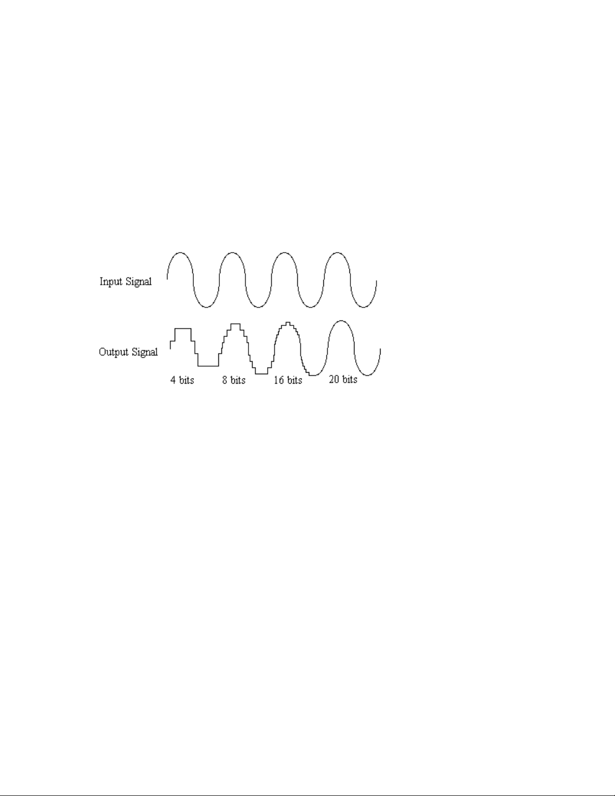
Sample Size
The more bits that are used to store the sampled value, the more closely it
will represent the source signal. In an 8-bit system, there are 256 possible
combinations of zeroes and ones, so 256 different analog voltages can be
represented. A 16-bit system provides 65,535 possible combinations. A 16bit signal is capable of providing far greater accuracy than an 8-bit signal.
Figure B
shows how this works.
Figure B. The more bits there are available, the more accurate
the representation of the signal and the greater the dynamic
range.
Layla’s analog inputs use 20-bit ADCs, which means that the incoming
signal can be represented by any of 1,048,576 possible values. The output
DACs are also 20-bit; again, 1,048,576 values are possible. The S/PDIF
inputs and outputs support signals with up to 24-bit resolution (16,777,216
possible values). Layla processes signals internally with 24-bit resolution to
insure that there is no degradation to the audio signal as it is processed
through the system.
The number of bits available also determines the potential dynamic range.
Moving a binary number one space to the left multiplies the value by two
(just as moving a decimal number one space to the left multiplies the value
by ten), so each additional bit doubles the maximum value that may be
represented. Each available bit provides 6dB of dynamic range. For
example, a 20-bit system can theoretically provide 120dB of dynamic range.
61
Page 62
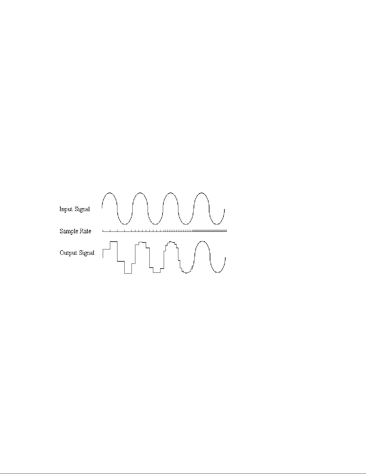
Sample Rate
The rate at which the ADC generates the numbers is equally important in
determining the quality of a digital recording. To get a high level of
accuracy when sampling, the sample rate must be greater than twice the
frequency being sampled. The mathematical statement of this is called the
Nyquist Theorem. When dealing with full-bandwidth sound (20Hz−20kHz),
you should sample at greater than 40,000 times per second (twice 20kHz).
Layla allows you to sample at rates up to 48,000 times per second.
If the sampling rate is lower than the frequency you are trying to record,
entire cycles of the waveform will be missed, and the result will not
resemble the proper waveform. When the sample rate is too low, the
resulting sound has diminished high frequency content.
Figure C. Increased sample rates yield a more accurate
reproduction of the source signal.
By the way, the circuits that generate the sample rate must be exceedingly
accurate. Any difference between the sample rate used for recording and the
rate used at playback will change the pitch of the recording, just as with an
analog tape playing at the wrong speed. Also, any unsteadiness, or jitter, in
the sample clock will distort the signal as it is being converted from or to
analog form.
62
Page 63

Storing Digital Data
Once the waveform has been transformed into digital bits, it must be stored.
When sampling in stereo at 48kHz using a 20-bit word size, the system has
to accommodate 1,920,000 bits per second. Though this is a lot of data, it is
well within the capabilities of personal computers.
Most computer-based digital recording systems record the data directly to
the computer’s hard disk. Today’s hard disks are capable of storing large
amounts of data, though the performance of hard drives can vary
substantially. The Echo Reporter program (included on the Layla CD-ROM)
will give you a general idea what the capabilities of your hard disk are and
how much information it can successfully store and retrieve. The speed and
size of your hard drive will be a major determining factor in how many
tracks of audio you will be able to simultaneously record and playback.
63
Page 64
Appendix E:
Specifications
Audio Performance
Analog in to analog out
Frequency Response: 10Hz – 22kHz,
Dynamic Range: 98dB
THD+n: <0.005%, 20Hz–22kHz, A-weighted
±
Hardware
Eight ¼
oversampling analog-to-digital converters
Ten ¼
"
TRS balanced analog inputs with precision 20-bit 128x
"
TRS balanced analog outputs with high-performance 20-bit 128x
0.5dB
oversampling digital-to-analog converters
Outputs individually switchable between +4dBu and –10dBV
S/PDIF digital I/O with up to 24-bit resolution
On-board 24-bit Motorola 56301 DSP (80 MIPS)
24-bit data resolution maintained throughout internal signal path
Word clock/superclock I/O
Support for continuous sample rates with single-Hertz resolution
64
Page 65
Index
A
adjusting record and playback
levels
analog resolution
analog-to-digital converter
appearance command
ASIO
audio connector cable
available devices
B
Background Mixing
· 34, 37
· 61
· 60
· 27, 29, 30
· 5, 43, 44
· 7
· 24
· 47
Background Mixing Priority Level
· 47
BIOS version
C
compact disk, contents
consumer mode
consumer output setting
contacting customer service
contents
Cool Edit Pro installation
· 8, 50
· 7
· 39, 52
· 40, 53
· 49
· 7
· 45
Echo Reporter
ECHODEL.EXE
H
hardware installation
I
input controls
interrupt conflicts
L
Layla installation
legacy
· 59
legacy cards
M
MIDI time code
MIDI time code settings
mixer device command
monitor controls
Monitor During Playback
N
· 7, 8, 50, 51, 63
· 12, 14
· 14
· 30
· 52, 55, 56, 57
· 8
· 56, 57, 58
· 36
· 41
· 27, 28
· 32
· 39
D
damping setting
· 42
digital-to-analog converter
driver installation
E
EasyTrim
· 31
Echo Console
Echo Console controls
· 21
· 26
· 30
· 60
new console command
O
output controls
P
PCI card, installation
PCI slots
· 14
Playback Buffer Size
65
· 27
· 33
· 14
· 47
Page 66

Playback Device
Plug-and-Play
· 46
· 55, 56, 57, 58, 59
Preferred Multitrack Devices
Priority
professional mode
professional output setting
R
rack mount box, cable
rack-mount box, installing
Record Device
· 47
· 39, 52
· 40, 53
· 7
· 15
· 46
REPORTER program errors
resolving interrupt conflicts
· 46
· 50
· 55
S/PDIF resolution
sample rate
sample size
· 60, 62
· 61
SAW compatibility mode
SCMS copy-protection
selecting a slot
software Installation
· 61
· 40
· 39, 52
· 14
· 21
static electricity, discharging
summary screen
superclock
synchronization clocks
system requirements
T
· 11
· 36
· 34, 43
· 7
· 14
S
S/PDIF
S/PDIF cabling
· 36
· 15, 17
S/PDIF output mode
S/PDIF output setting
S/PDIF recording
· 52
· 39
· 40, 53
tolerance setting
· 41
troubleshooting guide
W
word clock
· 35
· 50, 52
66
 Loading...