

Page 1

Operator’s
Manual
SRM-2620
Grass Trimmer /
Brushcutter
The engine exhaust from this product contains chemicals
known to the State of California to cause cancer, birth defects,
or other reproductive harm.
Read and understand all provided literature before
use. Failure to do so could result in serious injury.
Note:This product complies with CAN ICES-2/NMB-2.
X7502341703
© 07/2020 ECHO Incorporated
Page 2

TABLE OF CONTENTS SRM-2620
TABLE OF CONTENTS
Introduction................................................................................................................. 3
Servicing Information.................................................................................................. 3
Parts/Serial Number........................................................................................... 3
Service ............................................................................................................... 4
ECHO Consumer Product Support .................................................................... 4
Product Registration........................................................................................... 4
Additional Literature ........................................................................................... 4
Safety ......................................................................................................................... 5
Manual Safety Symbols and Important Information ........................................... 5
International Symbols......................................................................................... 6
Personal Condition and Safety Equipment ........................................................ 8
Equipment ........................................................................................................ 13
Emission Control . (Exhaust & Evaporative) ............................................................ 14
CARB And EPA Emissions Control Information ............................................... 14
Description ............................................................................................................... 16
Contents................................................................................................................... 17
Assembly.................................................................................................................. 18
Support Handle Installation .............................................................................. 18
Operation.................................................................................................................. 18
Operation With Blades ..................................................................................... 19
Blade Selection ................................................................................................ 20
Fuel .................................................................................................................. 22
Starting Cold Engine ........................................................................................ 25
Starting Warm Engine ...................................................................................... 26
Stopping Engine............................................................................................... 27
Applications...................................................................................................... 28
Operating Techniques - Nylon Line Head: ....................................................... 28
Operating Techniques - metal or plastic blade ................................................. 29
Reaction Forces ............................................................................................... 29
Blade Cutting Problems ................................................................................... 31
Maintenance............................................................................................................. 32
Skill Levels ....................................................................................................... 32
Maintenance Intervals ...................................................................................... 33
Air Filter............................................................................................................ 34
Fuel Filter ......................................................................................................... 35
Spark Plug........................................................................................................ 36
Cooling System ................................................................................................ 36
Exhaust System ............................................................................................... 38
Carburetor Adjustment ..................................................................................... 39
Lubrication........................................................................................................ 41
Nylon Line Head Disassembly Instructions...................................................... 42
Nylon Line Replacement .................................................................................. 42
Sharpening Metal Blades ................................................................................. 44
Troubleshooting........................................................................................................ 45
Storage..................................................................................................................... 47
Specifications ........................................................................................................... 48
Product Registration................................................................................................. 50
2 X7502341703
© 07/2020 ECHO Incorporated
Page 3
SRM-2620
INTRODUCTION
Specifications, descriptions and illustrative material in this literature are as
accurate as known at the time of publication, but are subject to change
without notice. Illustrations may include optional equipment and
accessories, and may not include all standard equipment.
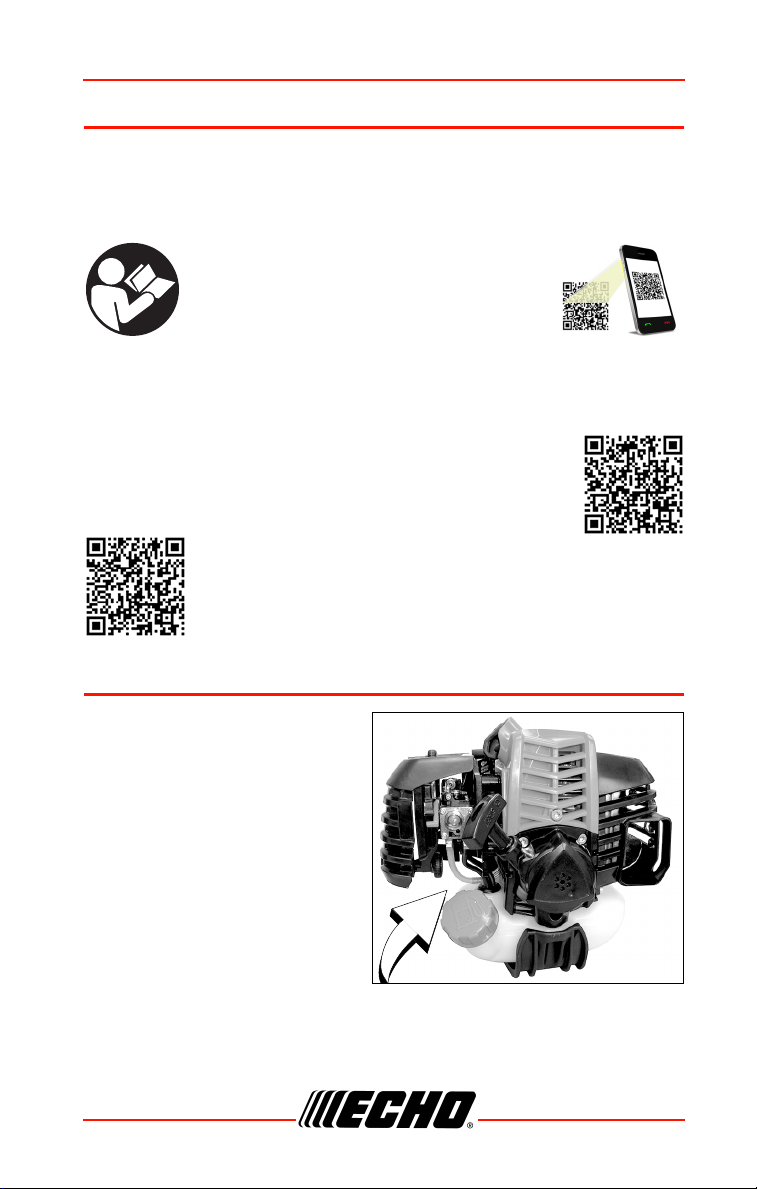
Read and understand all provided literature.
Literature contains specifications and
information for safety, operation,
maintenance, storage, and assembly
specific to this product. Scan QR codes for
more information.
For additional literature, including safety manuals where applicable, or
questions regarding terms used in this manual, visit:
https://www.echo-usa.com/manuals
OR
https://www.shindaiwa-usa.com/manuals
SERVICING INFORMATION
Parts/Serial Number
Genuine ECHO Parts and
Assemblies for your ECHO
products are available only from
an Authorized ECHO Dealer.
When you do need to buy parts
always have the Model Number
and Serial Number of the unit with
you. For future reference write
them in the space provided below.
Model No. _______________ Serial No. _______________
X7502341703 3
© 07/2020 ECHO Incorporated
Page 4

SERVICING INFORMATION SRM-2620
Service
Service of this product during the warranty period must be performed by an
Authorized ECHO Service Dealer. For the name and address of the
Authorized ECHO Service Dealer nearest you, ask your retailer or call:
1-800-432-ECHO (3246). Dealer information is also available on our Web
Site www.echo-usa.com. When presenting your unit for Warranty service/
repairs, proof of purchase is required.
ECHO Consumer Product Support
If you require assistance or have questions concerning the application,
operation, or maintenance of this product, call the ECHO Consumer
Product Support Department at 1-800-432-ECHO (3246) from 8:00 am to
5:00 pm (Central Standard Time) Monday through Friday. Before calling,
please know the model and serial number of your unit.
Product Registration
Register your ECHO equipment on-line at www.echo-usa.com or by filling
out the product registration sheet included in this manual. Registering your
product confirms warranty coverage and provides a direct link to ECHO if
we find it necessary to contact you.
Additional Literature
In addition to finding information online, information is available from your
Authorized ECHO Service Dealer, or by contacting ECHO Inc., 400
Oakwood Road, Lake Zurich, IL 60047 1-800-432-ECHO (3246).
4 X7502341703
© 07/2020 ECHO Incorporated
Page 5
SRM-2620
SAFETY
Manual Safety Symbols and Important Information
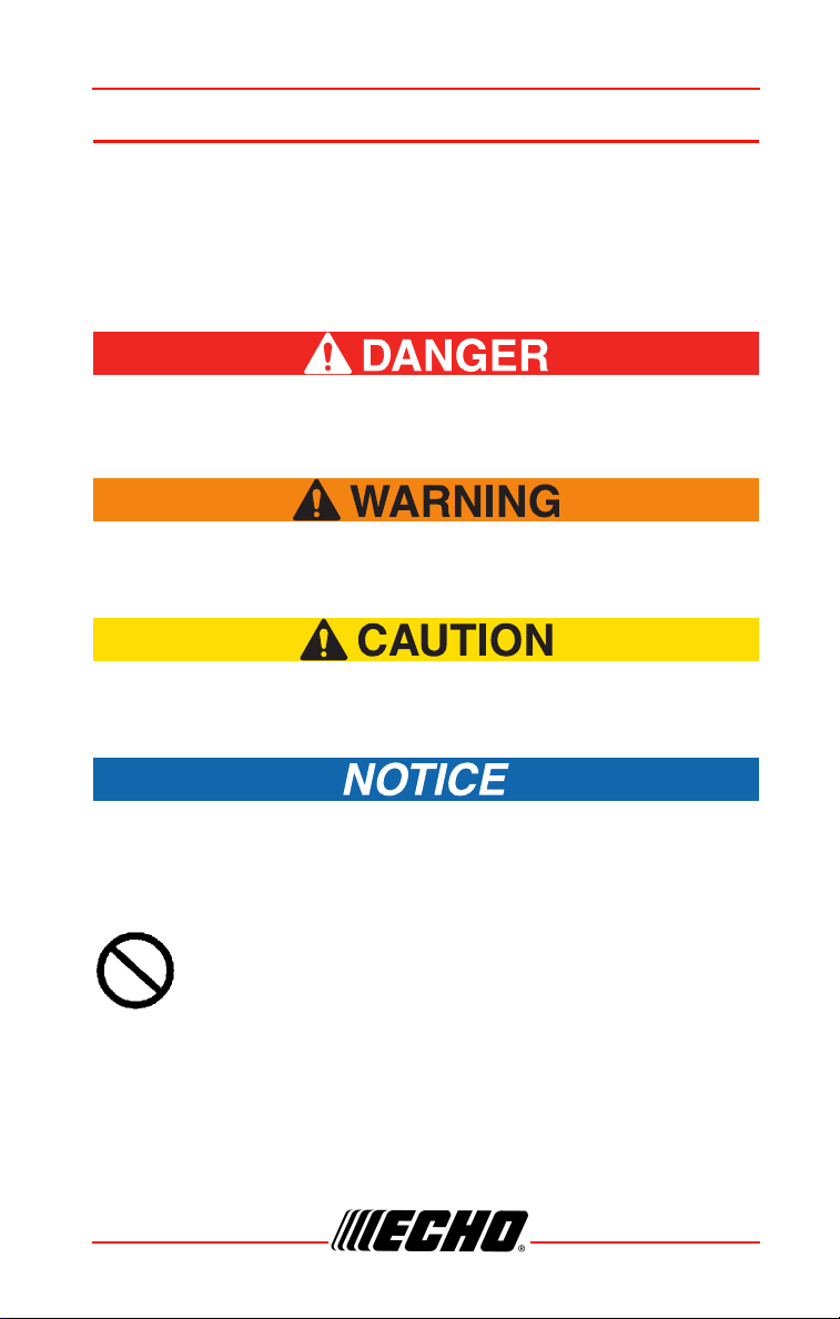
Throughout this manual and on the product itself, you will find safety alerts
and helpful, informational messages preceded by symbols or key words.
The following is an explanation of those symbols and key words and what
they mean to you.
The safety alert symbol accompanied by the word “DANGER”
calls attention to an act or condition which WILL lead to serious
personal injury or death if not avoided.
The safety alert symbol accompanied by the word “WARNING”
calls attention to an act or condition which CAN lead to serious
personal injury or death if not avoided.
The safety alert symbol accompanied by the word “CAUTION”
calls attention to an act or condition which might lead to minor
or moderate personal injury if not avoided.
The enclosed message provides information necessary for the
protection of the unit.
Note: This enclosed message provides tips for use, care and
maintenance of the unit.
CIRCLE AND SLASH SYMBOL
This symbol means the specific action shown is prohibited.
Ignoring these prohibitions can result in serious or fatal injury.
X7502341703 5
© 07/2020 ECHO Incorporated
Page 6
SAFETY SRM-2620
H
T
L
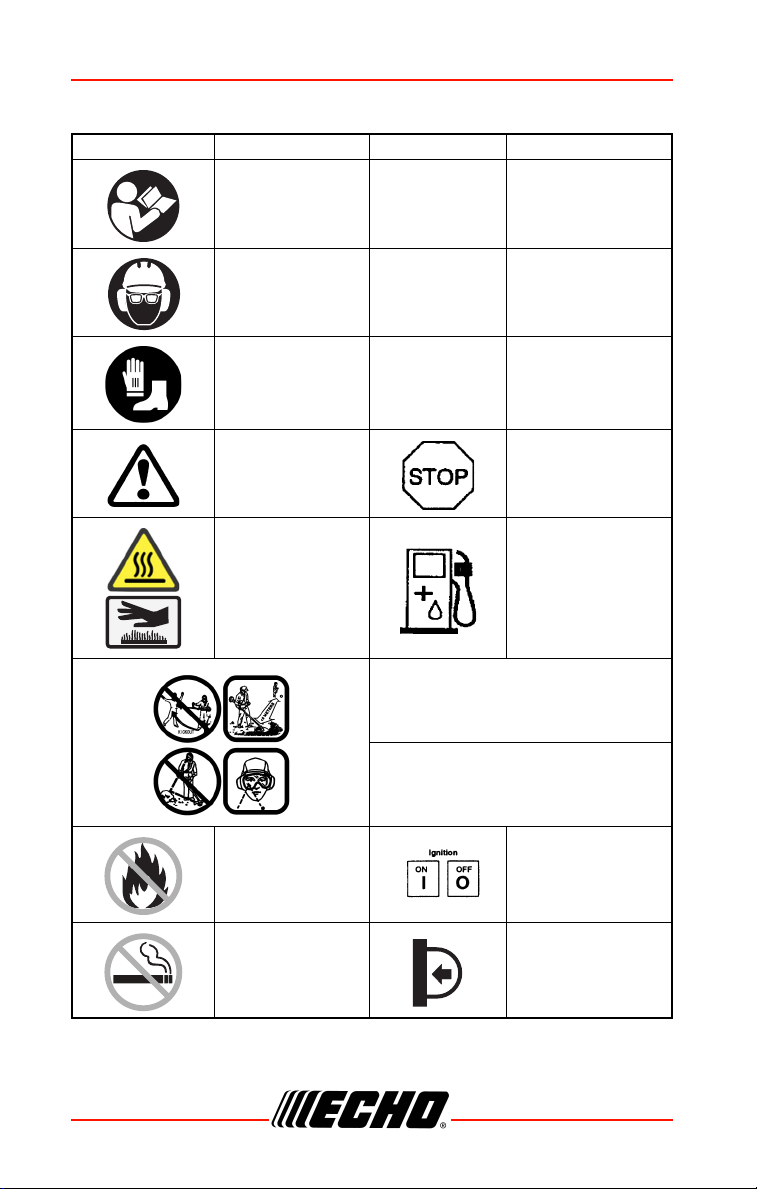
International Symbols
Symbol Description Symbol Description
Warning, See
Operator’s Manual
Wear Eye, Ear
and Head
Protection
Wear Hand and
Foot Protection
Safety/Alert STOP Switch
Hot Surface Fuel and Oil Mixture
AVOID KICKOUT
Keep Bystanders At Least 15 m (50
ft.) Away
Carburetor
Adjustment - High
Speed Mixture
Carburetor
Adjustment - Idle
Speed
Carburetor
Adjustment - Low
Speed Mixture
Beware Thrown Objects Wear Eye
DO NOT Allow
Flames or Sparks
Near Fuel
DO NOT Smoke
Near Fuel
6 X7502341703
Protection
Ignition
ON / OFF
Purge Bulb
© 07/2020 ECHO Incorporated
Page 7
SRM-2620
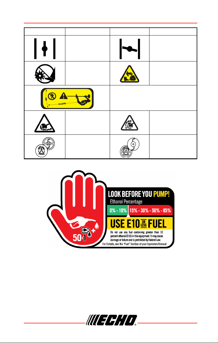
Symbol Description Symbol Description
Choke Control
“RUN” Position
(Choke Open)
Choke Control
“COLD START”
Position (Choke
Closed)
Keep Feet Away
From Blade
Keep Bystanders and Helpers
Away 15 m (50 ft.)
Thrown Objects Direction of Blade
DO NOT USE
LINE HEADS -
Blades Only
Note: Not all symbols will appear on your unit.
Rotating Cutting
Attachment
DO NOT USE
BLADES - Line
Heads Only
X7502341703 7
© 07/2020 ECHO Incorporated
Page 8
SAFETY SRM-2620
Personal Condition and Safety Equipment
Cancer and Reproductive Harm
www.P65Warnings.ca.gov
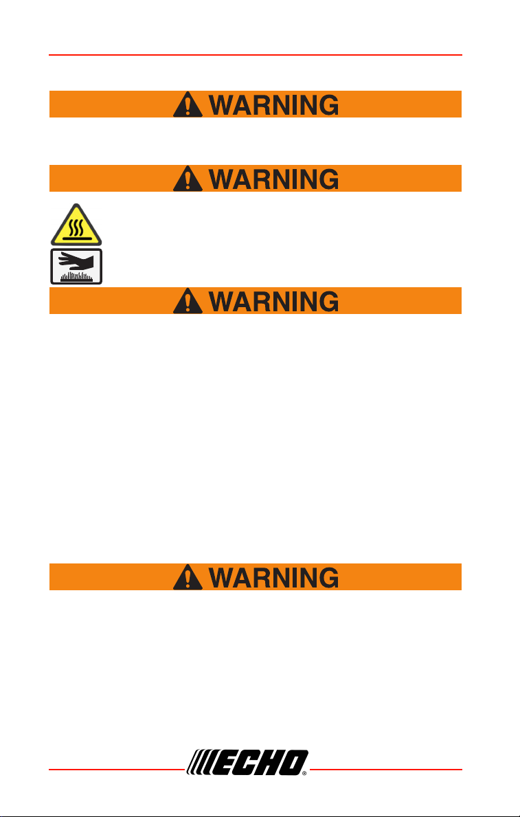
The muffler or catalytic muffler and surrounding cover
may become extremely hot. Always keep clear of
exhaust and muffler area, otherwise serious personal
injury might occur.
Users of this product risk injury to themselves and others if the
unit is used improperly and/or safety precautions are not
followed. Proper clothing and safety gear must be worn when
operating unit.
Physical Condition
Your judgment and physical dexterity may not be good:
• If you are tired or sick
• If you are taking medication
• If you have taken alcohol or drugs
Operate unit only if you are physically and mentally well.
Eye Protection
◆ Eye protection that meets ANSI Z87.1 or CE requirements
must be worn whenever you operate the unit.
◆ For additional safety, a full-face shield can be worn over
safety glasses or goggles to provide protection from sharp
branches or flying debris.
8 X7502341703
© 07/2020 ECHO Incorporated
Page 9

SRM-2620
Hand Protection
Wear sturdy, no-slip, rubber work gloves to improve your grip on the
handles. Gloves also provide protection against cuts and scratches, cold
environments, and reduce the transmission of machine vibration to your
hands.
Hearing/Ear Protection
ECHO recommends wearing personal protective equipment whenever unit
is used.
Breathing Protection
Operators who are sensitive to dust or other common airborne allergens
may need to wear a dust mask to prevent inhaling these materials while
operating unit. Dust masks can provide protection against dust, plant debris,
and other plant matter such as pollen. Make sure the mask does not impair
your vision, and replace the mask as needed to prevent air restrictions.
Proper Clothing
Wear snug-fitting, durable clothing:
• Pants should have long legs, shirts should have long sleeves.
• DO NOT WEAR SHORTS.
• DO NOT WEAR TIES, SCARVES, JEWELRY, or clothing with loose or
hanging items that could become entangled in moving parts or
surrounding growth.
• Keep clothing buttoned or zipped, and keep shirt tails tucked in.
• Wear sturdy work shoes with nonskid rubber soles.
• DO NOT WEAR OPEN TOED SHOES.
• DO NOT OPERATE UNIT WITH BARE FEET.
Keep long hair away from engine and air intake. Retain hair with cap or net.
Heavy protective clothing can increase operator fatigue, which may lead to
heat stroke. Schedule heavy work for early morning or late afternoon hours
when temperatures are cooler.
X7502341703 9
© 07/2020 ECHO Incorporated
Page 10
SAFETY SRM-2620
The components of this machine generate an electromagnetic
field during operation, which can interfere with some
pacemakers. To reduce the risk of serious or fatal injury,
persons with pacemakers should consult with their physician
and the pacemaker manufacturer before operating this
machine. In the absence of such information, ECHO does not
recommend the use of this machine by anyone who has a
pacemaker.
Extended Operation / Extreme Conditions
Prolonged exposure to cold and/or vibration can result in injury.
Read and follow all safety and operation instructions to
minimize risk of injury. Failure to follow instructions can result
in painful wrist/hand/arm injuries.
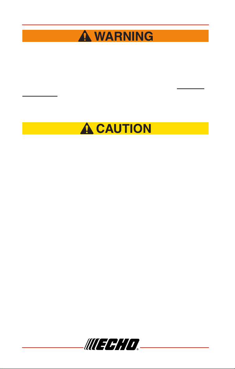
It is believed that a condition called Raynaud’s Phenomenon, which affects
the fingers of certain individuals, may be brought about by exposure to
vibration and cold. Exposure to vibration and cold may cause tingling and
burning sensations, followed by loss of color and numbness in the fingers.
The following precautions are strongly recommended, because the
minimum exposure, which might trigger the ailment, is unknown.
• Keep your body warm, especially the head, neck, feet, ankles, hands, and
wrists.
• Maintain good blood circulation by performing vigorous arm exercises
during frequent work breaks, and also by not smoking.
• Limit the hours of operation. Try to fill each day with jobs where operating
the unit or other hand-held power equipment is not required.
• If you experience discomfort, redness, and swelling of the fingers
followed by whitening and loss of feeling, consult your physician before
further exposing yourself to cold and vibration.
10 X7502341703
© 07/2020 ECHO Incorporated
Page 11
SRM-2620
Repetitive Stress Injuries (RSI)
It is believed that overusing the muscles and tendons of the fingers, hands,
arms, and shoulders may cause soreness, swelling, numbness, weakness,
and extreme pain in those areas. Certain repetitive hand activities may put
you at a high risk for developing a Repetitive Stress Injury (RSI). An
extreme RSI condition is Carpal Tunnel Syndrome (CTS), which could occur
when your wrist swells and squeezes a vital nerve that runs through the
area. Some believe that prolonged exposure to vibration may contribute to
CTS. CTS can cause severe pain for months or even years.
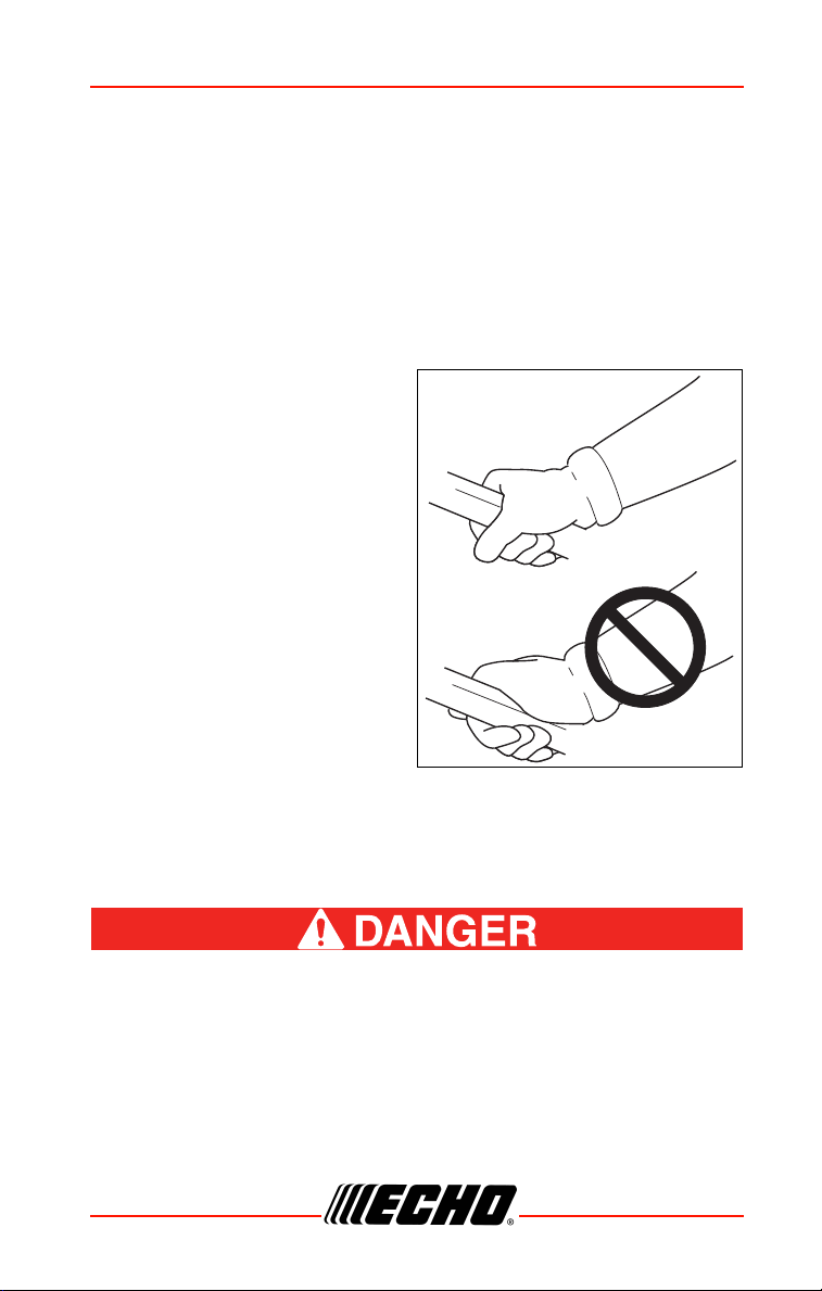
To reduce the risk of RSI/CTS, do
the following:
• Avoid using your wrist in a bent,
extended, or twisted position.
Instead try to maintain a straight
wrist position. Also, when
grasping, use your whole hand,
not just the thumb and index
finger.
• Take periodic breaks to minimize
repetition and rest your hands.
• Reduce the speed and force with
which you do the repetitive
movement.
• Do exercises to strengthen the
hand and arm muscles.
• Immediately stop using all power equipment and consult a doctor if you
feel tingling, numbness, or pain in the fingers, hands, wrists, or arms. The
sooner RSI/CTS is diagnosed, the more likely permanent nerve and
muscle damage can be prevented.
All over head electrical conductors and communications wires
can have electricity flow with high voltages. This unit is not
insulated against electrical current. Never touch wires directly
or indirectly, otherwise serious injury or death can result.
X7502341703 11
© 07/2020 ECHO Incorporated
Page 12

SAFETY SRM-2620
Do not operate this product indoors or in inadequately
ventilated areas. Engine exhaust contains poisonous emissions
and can cause serious injury or death.
Read Manuals
• Provide all users of this equipment with literature for instructions on safe
operation.
Clear The Work Area
• Always clear the work area of foreign objects such as rocks, broken
glass, nails, wire, or string,, and check for any hidden hazards. Spectators
and fellow workers must be warned, and children and animals prevented
from coming nearer than 50 ft. (15 m) while the unit is in use.
• Outside the 15 m (50 ft) zone, there is still a risk of injury from thrown
objects.
• Bystanders should be encouraged to wear eye protection.
• If you are approached, stop the engine and cutting attachment.
• When a bladed unit is used, there is the added risk of injury to bystanders
being struck with the moving blade in the event of a blade thrust or other
unexpected reaction of the blade.
Keep A Firm Grip
• Always hold throttle handle and support handle with thumbs and fingers
tightly encircling the handles.
Keep A Solid Stance
• Maintain footing and balance at all times. Do not stand on slippery,
uneven or unstable surfaces. Do not work in odd positions or on ladders.
Do not over reach.
• Keep cutting attachment below waist.
• Keep all body parts away from rotating cutting attachment
Avoid Hot Surfaces
• Keep exhaust area clear of flammable debris. Avoid
contact during and immediately after operation.
12 X7502341703
© 07/2020 ECHO Incorporated
Page 13

SRM-2620
Equipment
Use only approved attachments. Serious injury may result from
the use of a non-approved attachment combination. ECHO INC.
will not be responsible for the failure of cutting devices,
attachments or accessories which have not been tested and
approved by ECHO INC. Read and comply with all safety
instructions.
◆ Do not attempt to modify this product. Serious injury can
result from the use of any modified product.
◆ Check unit for loose or missing nuts, bolts, and screws.
Tighten or replace as needed.
◆ Inspect shield for damage and ensure that shield is
properly installed, and that the cut-off knife is securely in
place. Replace if either is damaged or missing.
◆ Check that the cutting attachment is firmly attached and in
safe operating condition.
◆ Manufacturer recommended flexible non-metallic line is
installed in the trimmer head.
◆ Assure that throttle trigger, throttle trigger lockout, and
stop switch all work properly.
◆ Check that handle and harness (if included) are installed
and adjusted for safe, comfortable operation. See
Assembly Section for proper adjustment.
Moving parts can amputate fingers or cause severe injuries.
Keep hands, clothing and loose objects away from all openings.
◆ ALWAYS stop engine, disconnect spark plug, and make
sure all moving parts have come to a complete stop before
assembling unit, removing obstructions, clearing debris,
or servicing unit.
◆ Do not connect spark plug lead to spark plug unitl unit is
ready for use.
◆ DO NOT start or operate unit unless all guards and
protective covers are properly assembled to unit.
◆ NEVER reach into any opening while the engine is running.
Moving parts may not be visible through openings.
X7502341703 13
© 07/2020 ECHO Incorporated
Page 14
EMISSION CONTROL SRM-2620
◆ Position wiring safely to prevent snagging, separation of
connectors, or breakage during operation. Gather excess
wire, and secure with wiring clamp if provided on
equipment, or tuck behind the air filter area. Do not place
wiring directly against hot engine components.
◆ Check wiring and connectors for nicks, cuts, exposed wire,
or other damage, and repair or replace as needed. Exposed
wire or connectors can cause shocks, sparks, and risk of
fire or explosion, resulting in serious injury.
◆ Check wire terminals for secure connections.
Periodically Check fuel system (fuel lines, vent, grommet, fuel
tank, and fuel cap) for leaks especially if the unit is dropped. If
damage or leaks are found, do not use unit, otherwise serious
personal injury or property damage may occur. Have unit
repaired by an authorized servicing dealer before using.
EMISSION CONTROL (EXHAUST &
EVAPORATIVE)
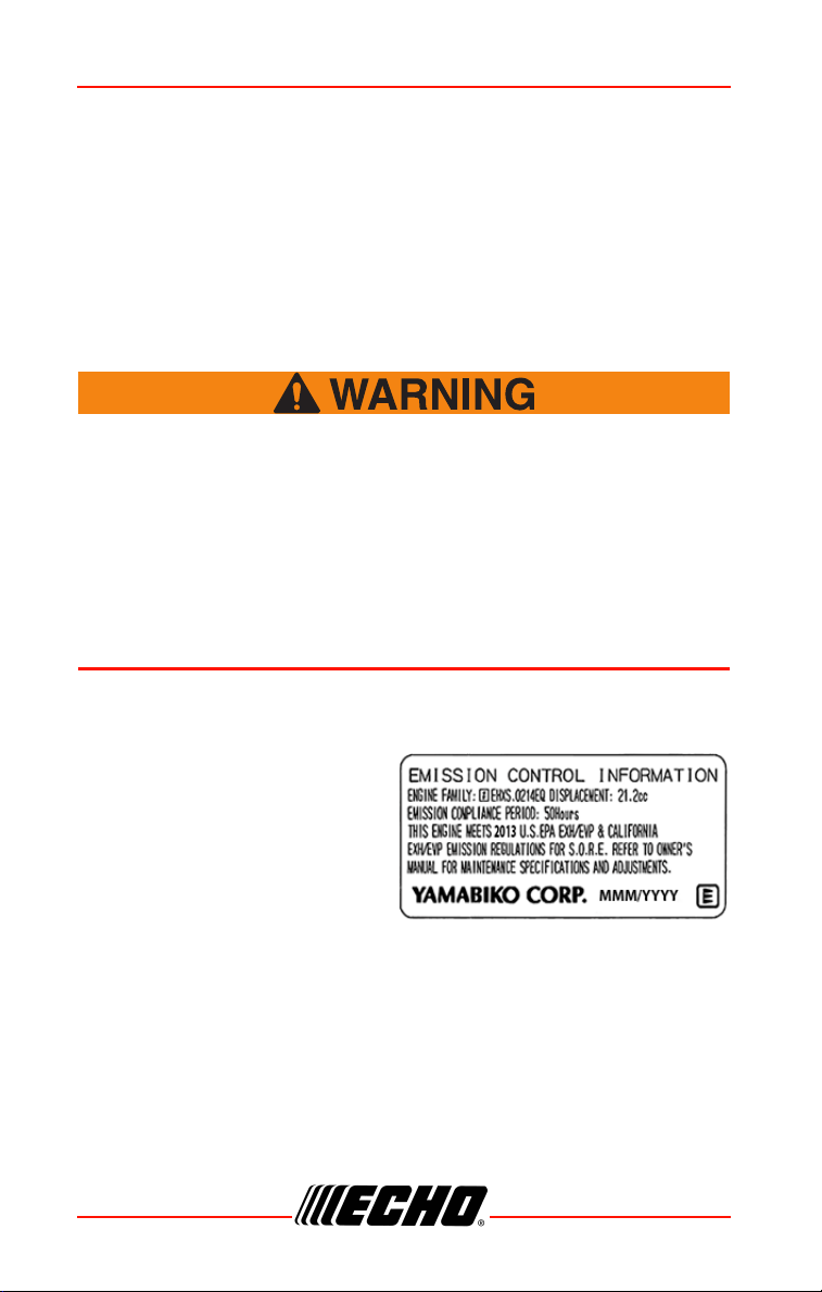
CARB And EPA Emissions Control Information
The emission control system for
the engine is EM (engine
modification) and, if the second to
last character of the Engine Family
on the Emission Control
Information label (sample below) is
“B”, “C”, “K”, or “T”, the emission
control system is EM and TWC (3way catalyst). The fuel tank/fuel
line emission control system is EVAP (evaporative emissions). Evaporative
emissions for California models are only applicable to fuel tanks and fuel
feed lines.
14 X7502341703
© 07/2020 ECHO Incorporated
Page 15

SRM-2620
An Emission Control Label is
located on the engine. (This is an
EXAMPLE ONLY, information on
label varies by engine FAMILY).
Product Emission Durability (Emission Compliance Period)
The 50 or 300 hour emission compliance period is the time span selected by
the manufacturer certifying the engine emissions output meets applicable
emissions regulations, provided that approved maintenance procedures are
followed as listed in the Maintenance Section of this manual.
X7502341703 15
© 07/2020 ECHO Incorporated
Page 16
DESCRIPTION SRM-2620
DESCRIPTION
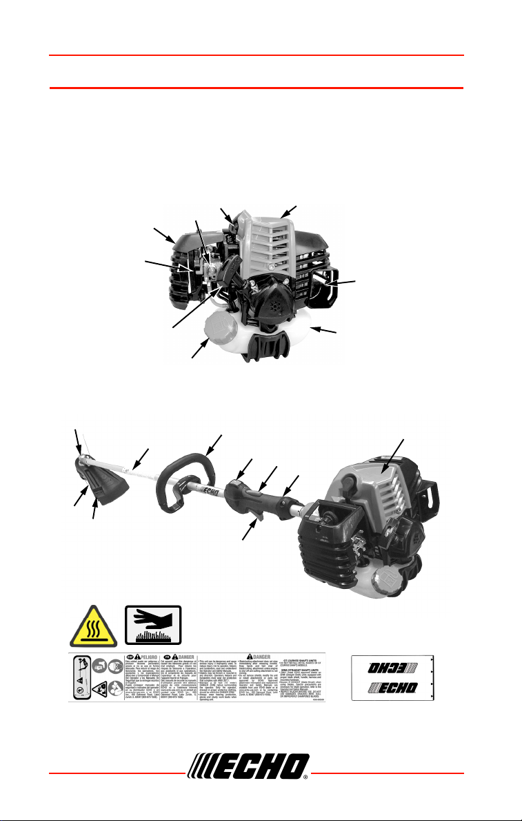
Locate the safety decal(s) on your unit. Make sure the decal(s) is legible
and that you understand and follow the instructions on it. If a decal cannot
be read, a new one can be ordered from your ECHO dealer. Safety label is
for example only. Your label my appear slightly different.
17
10
18
14
5
6
7
16
15
4
11
3
9
8
12
13
19
2
1
16 X7502341703
© 07/2020 ECHO Incorporated
Page 17

SRM-2620
1. Choke
2. Air Cleaner
3. Purge Bulb
4. Spark Plug
5. Arm Rest
6. Spark Arrestor Muffler Or Spark Arrestor Muffler With Catalyst
7. Fuel Tank
8. Fuel Tank Cap
9. Recoil Starter Handle
10. Nylon Cutter Head
11. Drive Shaft Assembly
12. Support Handle - For Left Hand
13. Stop Switch
14. Throttle Trigger Lockout
15. Throttle Handle - For Right Hand
16. Power Head
17. Debris Shield With Cut-off Knife
18. Cut-off Knife
19. Throttle Trigger
CONTENTS
The ECHO product you purchased has been factory pre-assembled for your
convenience. Due to packaging restrictions, some assembly may be
necessary.
After opening the carton, check for damage. Immediately notify your retailer
or ECHO Dealer of damaged or missing parts. Use the contents list to check
for missing parts.
1 Power Head / Drive Shaft Assembly
1 Quick Start Guide
1 Warranty Statement
X7502341703 17
© 07/2020 ECHO Incorporated
Page 18
ASSEMBLY SRM-2620
MINIMUM
SPACING
ASSEMBLY
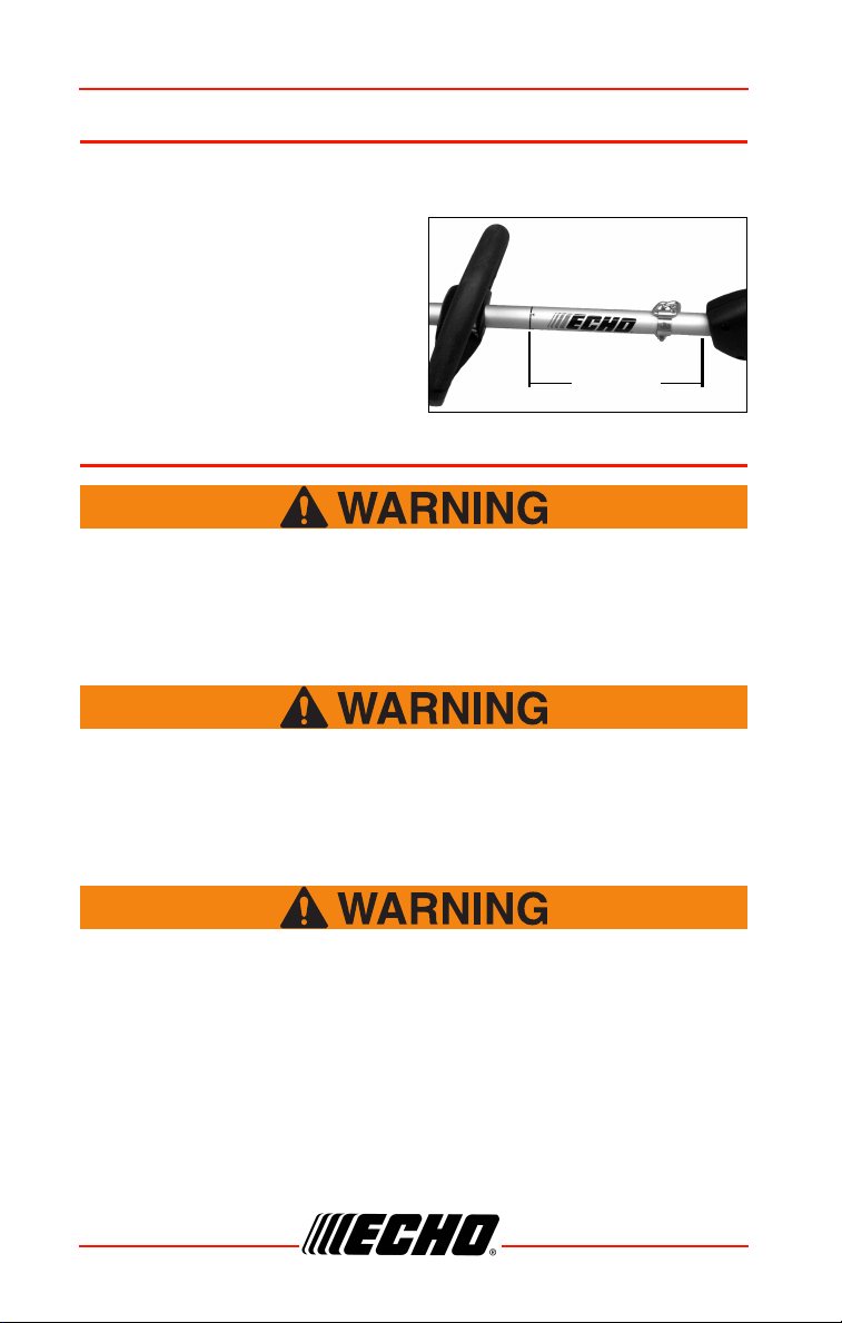
Support Handle Installation
Note: Label shows minimum
spacing for support handle
location.
1. If necessary, position support
handle for comfortable operation
and securely tighten screws.
OPERATION
Moving parts can amputate fingers or cause severe injuries.
Keep hands, clothing and loose objects away from all openings.
Always stop engine, disconnect spark plug, and make sure all
moving parts have come to a complete stop before removing
obstructions, clearing debris, or servicing unit.
Engine exhaust IS HOT, and contains Carbon Monoxide (CO), a
poison gas. Breathing CO can cause unconsciousness, serious
injury, or death. Exhaust can cause serious burns. ALWAYS
position unit so that exhaust is directed away from your face
and body.
Operation of this equipment may create sparks that can start
fires around dry vegetation. This unit is equipped with a spark
arrestor to prevent discharge of hot particles from the engine.
Metal cutters can also create sparks if the cutter strikes rocks,
metal, or other hard objects. Contact local fire authorities for
laws or regulations regarding fire prevention requirements.
18 X7502341703
© 07/2020 ECHO Incorporated
Page 19
SRM-2620
Operation With Blades
Metal blades are very sharp and can cause severe injuries, even
if engine is off and blades are not moving. Avoid contact with
blades. Wear gloves to protect hands.
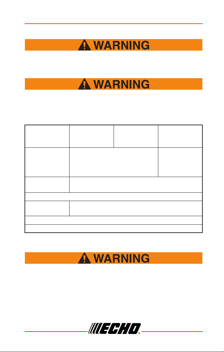
Blade use demands specific brush cutter configuration.
Operation without specified shield, barrier bar or U-handle, and
harness can result in serious personal injury. Follow installation
instructions.
Pro Maxi-Cut
Grass/Weed
Blade
Tri-Cut Grass/
Weed Blade
Metal Grass /
Weed Blade
Metal Brush /
Clearing
Blades
Support
Handle, with or
without Barrier
U-Handle or Support Handle with
Barrier Bar
U-handle*
Bar
Shield with
cutoff knife
Shield without cutoff knife
Harness
Upper Plate &
Flat Washer
Upper/Lower Blade Plates
Hex Nut
New Cotter Pin
*ANSI standards require brush cutters be equipped with a barrier bar or
restrictive harness. U-Handle ensures a higher safety factor.
Do Not install blades on GT (Curved Shaft) model trimmers.
• Use only ECHO approved parts. Failure to use the correct parts can
cause the blade to fly off. Seriously injury to the operator and / or
bystanders can occur.
• Arbor diameter of upper blade plate must match arbor diameter of blades.
X7502341703 19
© 07/2020 ECHO Incorporated
Page 20
OPERATION SRM-2620
• For barrier bar or u-handle, follow instructions supplied with either blade
conversion kit or U-handle kit, and verify blade is secured properly.
• A new cotter pin is required each time a blade is installed.
• Shoulder harnesses may be used on all trimmers and brushcutters to
reduce operator fatigue. Brushcutters over 7.5 kg (16.5 lbs.) dry weight
(without fuel) and u- handle brushcutters REQUIRE a double shoulder
harness.
Note: The barrier bar is used to restrict rearward movement
of the unit. The barrier bar is not a handle and should
not be gripped when using or carrying the unit.
Blade Selection
The type of blade used MUST be matched to the type and size of
material cut. An improper or dull blade can cause serious
personal injury. Blades MUST be sharp. Dull blades increase the
chance of kick-out and injury to yourself and bystanders. Never
use an edging blade, circular saw blade, or any other type of
unapproved blade.
3-Tooth Grass/Weed Blades may be used wherever the nylon line head is
used. DO NOT use this blade for heavy weeds or brush.
8 Tooth Weed/Grass Blade is designed for grass, garden debris and thick
weeds up to 19 mm (0.75 in.) diameter. DO NOT use this blade for brush or
heavy woody growth.
80 Tooth Brush Blade is designed for cutting brush and woody growth up
to 13 mm (0.5 in.) diameter.
22 Tooth Clearing Blade is designed for dense thickets and saplings up to
64 mm (2.5 in.) diameter.
A trimmer-brushcutter with a metal blade can cause serious
injuries if handled improperly.
20 X7502341703
© 07/2020 ECHO Incorporated
Page 21
SRM-2620
Always use extreme care when
carrying or handling the equipment
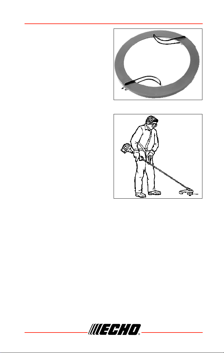
to avoid contact with the cutting
edges of the blade. Use the optional
blade cover when unit is not in use.
Keep blades in protective packaging
until ready to install. Store blades
safely after removal to prevent injury
from accidental contact.
Use blade protectors to protect
blade teeth during unit
transportation.
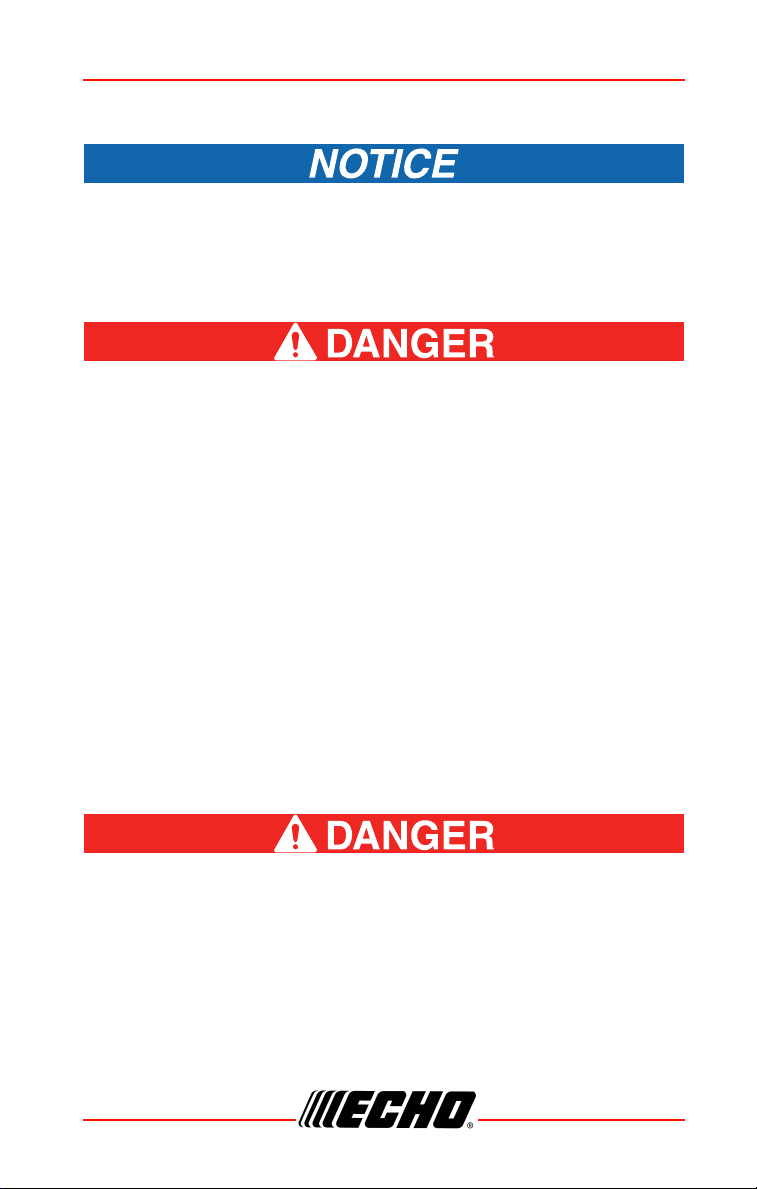
Use Shoulder/Waist Harness
Use of the shoulder/waist harness is
recommended for ALL trimmer/
brushcutter use, not just blade
operation. The shoulder/waist
harness when used in a trimming
operation with nylon line head
suspends the trimmer from the
operator's shoulder and reduces
operator fatigue.
During blade operation, the same
fatigue reduction is achieved. Safety
to the operator is also enhanced by
reducing the possibility of blade
contact with the operator's hands and feet by restricting trimmer movement.
Make sure the warning sign on the back of the shoulder harness can be
read easily.
Note: In case of Emergency, disconnect the trimmer from the
harness.
X7502341703 21
© 07/2020 ECHO Incorporated
Page 22

OPERATION SRM-2620
Fuel
Diesel fuels and alternative fuels, such as E-15 (15% ethanol),
E-85 (85% ethanol) or any fuels not meeting ECHO requirements
are NOT approved for use in ECHO 2-stroke gasoline engines.
Use of diesel or alternative fuels can cause performance
problems, loss of power, overheating, fuel vapor lock, and
unintended machine operation, including, but not limited to,
improper clutch engagement. Diesel or alternative fuels can
also cause premature deterioration of fuel lines, gaskets,
carburetors and other engine components.
Fuel Requirements
Gasoline - Use fresh (purchased within the last 30 days from the pump) 89
Octane [R+M/2] (mid grade or higher) gasoline known to be good quality.
Gasoline may contain up to 10% Ethanol (grain alcohol) or 15% MTBE
(methyl tertiary-butyl ether). Gasoline containing methanol (wood alcohol) is
NOT approved. Use of ECHO branded fuel is recommended to extend
engine life in all air-cooled 2-stroke and 2/4-stroke hybrid engines.
Two Stroke Oil - A two-stroke engine oil, such as ECHO branded 2-stroke
oils, meeting ISO-L-EGD (ISO/CD 13738) and J.A.S.O. FD Standards must
be used. ECHO branded 2-stroke oils meet these standards. Engine
problems due to inadequate lubrication caused by failure to use an ISO-LEGD (ISO/CD 13738) and J.A.S.O. M345-FD certified oil will void the twostroke engine warranty.
2-Stroke engine oil contains petroleum distillates and other
additives that may be harmful if swallowed. Heated oil can
release vapors that can cause flash fire, or ignite with explosive
force. Read and follow the oil manufacturer’s instructions, and
observe all safety warnings and precautions for handling
flammable liquids. For more detailed safety and first aid
information, visit www.echo-usa.com for a copy of the Material
Safety Data Sheet.
◆ KEEP OUT OF REACH OF CHILDREN.
◆ If swallowed, do not induce vomiting. CALL PHYSICIAN OR
A POISON CONTROL CENTER IMMEDIATELY.
◆ WEAR SAFETY GLASSES when mixing or handling.
22 X7502341703
© 07/2020 ECHO Incorporated
Page 23
SRM-2620
◆ AVOID repeated or prolonged skin contact.
◆ AVOID inhaling oil mists or vapors.
ECHO branded 2-stroke oils may be mixed at 50:1 ratio for
application in all ECHO engines sold in the past regardless of ratio
specified in those manuals.
Handling Fuel
Fuel is VERY flammable. Use extreme care when mixing, storing
or handling, or serious personal injury will result.
◆ Use an approved fuel container. Mark fuel containers as
containing 2-stroke mixture fuel.
◆ DO NOT smoke near fuel.
◆ DO NOT allow flames or sparks near fuel.
◆ Fuel tanks/cans may be under pressure. Always loosen
fuel caps slowly allowing pressure to equalize.
◆ NEVER refuel a unit when the engine is HOT or RUNNING!
◆ DO NOT fill fuel tanks indoors. ALWAYS fill fuel tanks
outdoors over bare ground.
◆ DO NOT overfill fuel tank. Wipe up spills immediately.
◆ Securely tighten fuel tank cap and close fuel container
after refueling.
◆ Inspect for fuel leakage. If fuel leakage is found, do not
start or operate unit until leakage is repaired.
◆ Move at least 3 m (10 ft.) from refueling location before
starting the engine.
Gasoline vapor is heavier than air, and can travel along the
ground to nearby sources of ignition such as electrical motors,
pilot lights, and hot or running engines. Vapors ignited by an
ignition source can flash back to the fuel container, resulting in
an explosion, fire, serious or fatal injuries, and extensive
property damage.
X7502341703 23
© 07/2020 ECHO Incorporated
Page 24
OPERATION SRM-2620
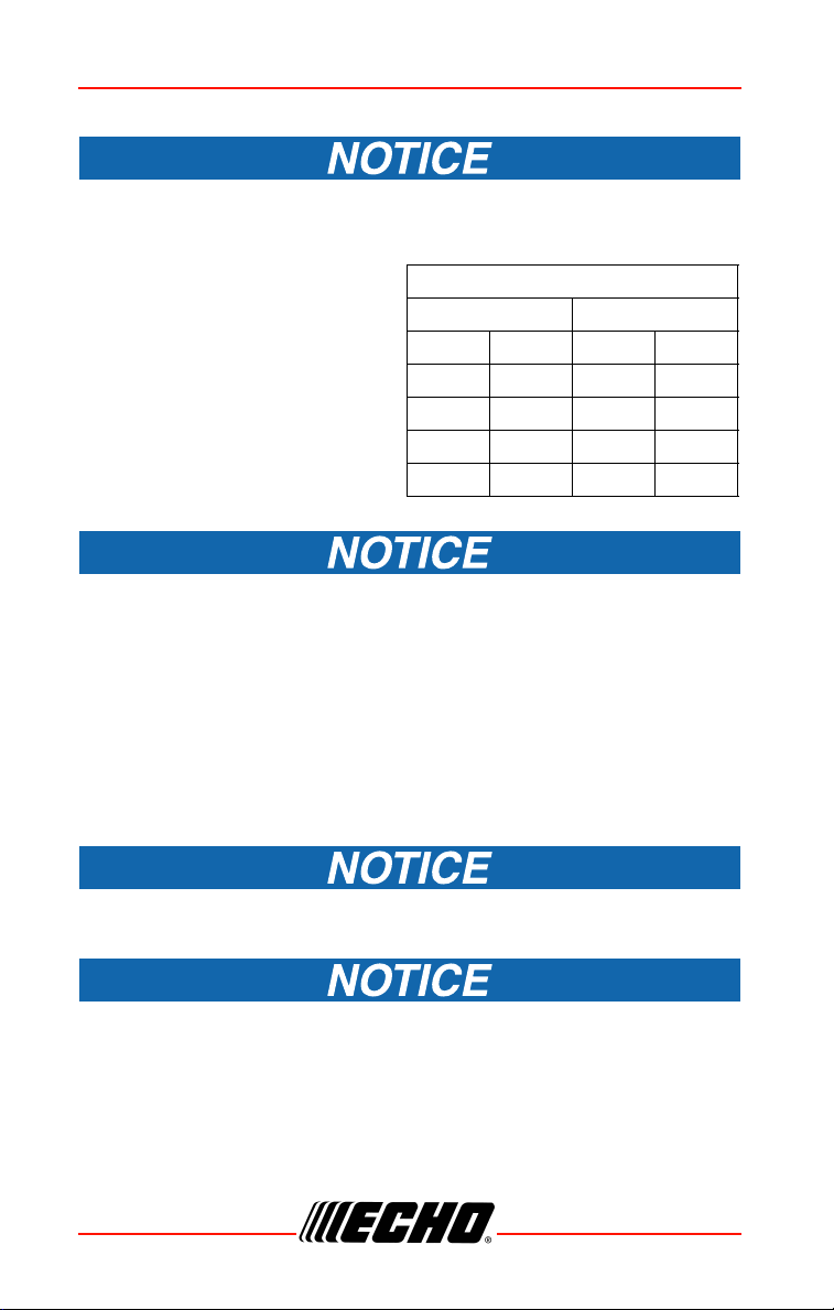
Fuel to Oil Mix – 50:1 Ratio
US Metric
Gas Oil Gas Oil
gal. fl.oz. L cc
12.65100
2 5.2 10 200
51325500
Mixing Instructions
Stored fuel ages. Do not mix more fuel than you expect to use in 30
days, 90 days when a fuel stabilizer is added.
1. Fill an approved fuel container
with half of the required
amount of gasoline.
2. Add the proper amount of
2-stroke oil to gasoline.
3. Close container and shake to
mix oil with gasoline.
4. Add remaining gasoline, close
fuel container, and remix.
Spilled fuel is a leading cause of hydrocarbon emissions. Some
locations may require the use of automatic fuel shut-off containers to
reduce fuel spillage.
Storage - Fuel storage laws vary by locality. Contact your local government
for the laws affecting your area. As a precaution, store fuel in an approved,
airtight container. Store in a well-ventilated, unoccupied building, away from
sparks and flames.
• Empty the fuel tank prior to storing the unit. Return unused fuel to an
approved fuel storage container.
Stored two-stroke fuel can separate. ALWAYS shake fuel container
thoroughly before each use.
Used oil and gasoline, and soiled towels are hazardous waste
materials. Disposal laws vary by locality.
24 X7502341703
© 07/2020 ECHO Incorporated
Page 25
SRM-2620
A
B
C
D
Starting Cold Engine
The attachment will operate immediately when the engine
starts, and could result in possible serious injury. Keep
movable parts of the attachment away from objects that could
become entangled or thrown, and surfaces that could cause
loss of control.
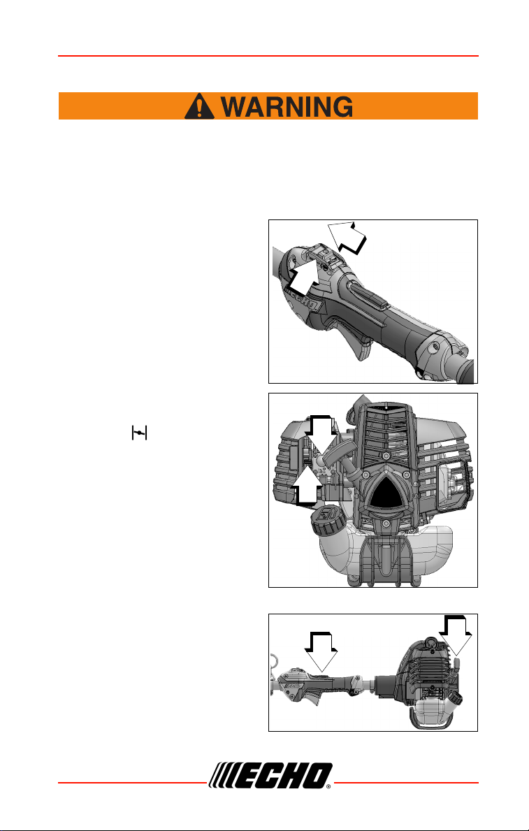
1. Stop Switch
Move stop switch button (A)
forward, away from the STOP
position.
2. Choke
Move choke lever (B) to COLD
START ( ) position.
3. Purge Bulb
Pump purge bulb (C) until fuel is
visible and flows freely in the
clear fuel tank return line. Pump
bulb an additional 4 or 5 times.
4. Recoil Starter
Lay the unit on a flat area and
keep movable attachment parts
clear of all obstacles. Firmly
grasp throttle handle and throttle
trigger lockout with left hand and
fully depress throttle trigger to
wide open position. Rapidly pull
recoil starter handle/rope (D)
until engine fires (or maximum 2-3 pulls).
X7502341703 25
© 07/2020 ECHO Incorporated
Page 26

OPERATION SRM-2620
A
5. Choke
After engine fires (or two to three pulls), move choke to the RUN ( )
(open) position. Firmly grasp throttle handle and throttle trigger lockout
with left hand and fully depress throttle trigger to wide open position. Pull
starter handle/rope (D) until engine starts and runs. Release throttle
trigger and allow unit to warm up at idle for several minutes.
Note: If engine does not start with choke in “RUN” position after 2-3
pulls, repeat instructions 2 - 5.
6. Throttle Trigger
After engine warm-up, grip throttle handle and support handle. Depress
the throttle trigger lockout, and gradually depress throttle trigger to
increase engine RPM to operating speed.
Starting Warm Engine
The starting procedure is the same as Cold Start except DO NOT close the
choke, and do not hold throttle trigger fully depressed.
The attachment should not move at idle, otherwise serious
personal injury may result.
Note: If attachment moves, readjust carburetor according to
“Carburetor Adjustment” instructions in this manual or see
your ECHO Dealer.
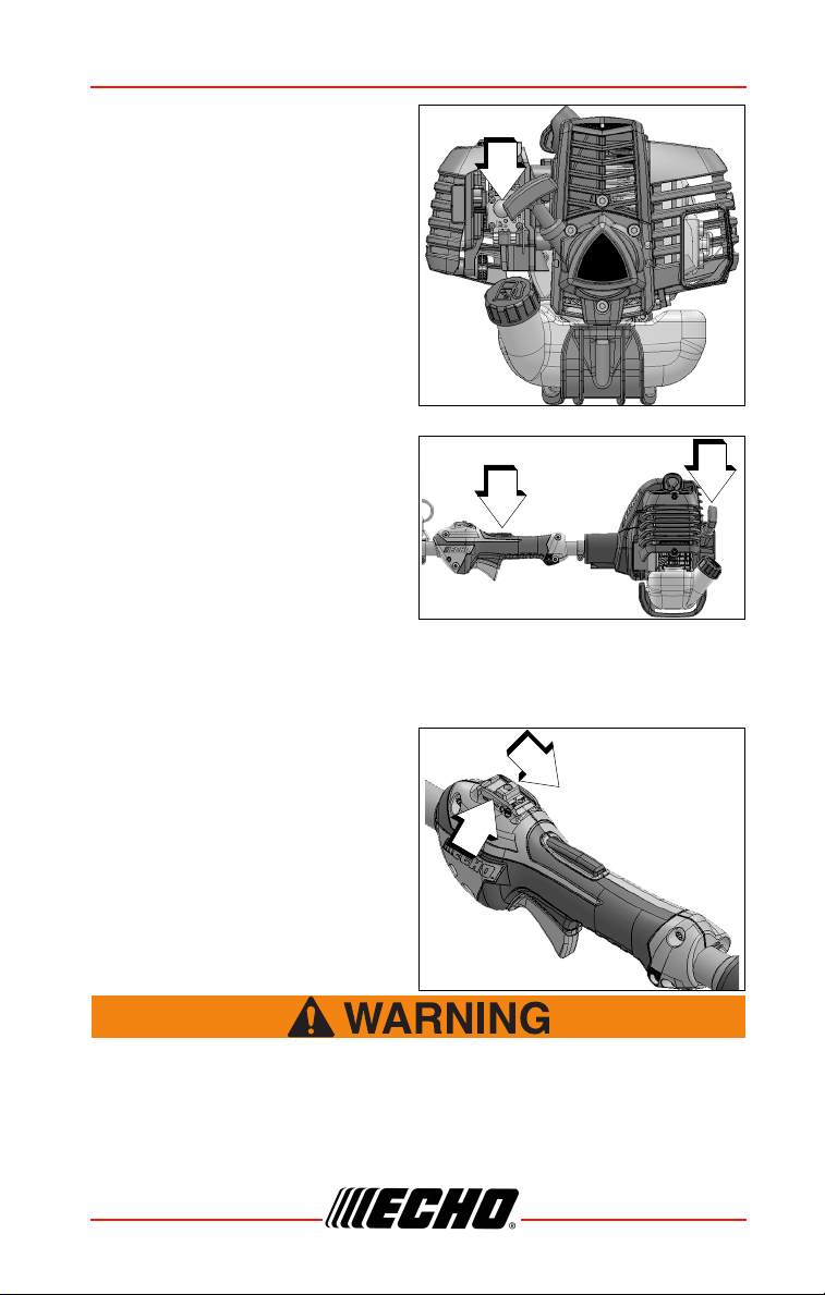
1. Stop Switch
Move stop switch button (A)
forward away from the STOP
position.
26 X7502341703
© 07/2020 ECHO Incorporated
Page 27
SRM-2620
B
D
A
2. Purge Bulb
Pump purge bulb (B) until fuel is
visible in the “Clear” fuel return
line. Pump bulb an additional 4
or 5 times.
3. Recoil Starter
Lay the unit on a flat area and
keep movable attachment parts
clear of all obstacles. Firmly grip
throttle handle and throttle
trigger lockout with left hand.
Rapidly pull recoil starter
handle/rope (D) until engine
fires.
Note: If engine does not start after 2-3 pulls, use Cold Start
Procedure.
Stopping Engine
1. Throttle
Release throttle trigger and
allow engine to return to idle
before shutting off engine.
2. Stop Switch
Move stop switch button (A)
backward to STOP position.
If engine does not stop when stop switch is moved to STOP
position, close choke - COLD START position - to stall engine.
Have your ECHO dealer repair stop switch before using unit
again.
X7502341703 27
© 07/2020 ECHO Incorporated
Page 28

OPERATION SRM-2620
Applications
Do Not install blades on GT (Curved Shaft) or T model trimmers.
Operating Techniques - Nylon Line Head:
Nylon line heads may be used for trimming, scything, edging, and scalping
of grass and light weeds.
Trimming
Feed the spinning line into the material to be cut. Tilt the line head to one
side to direct cutting debris away from you:
• Model SRM/PAS/SB/TX/C/T (Straight shaft, counter-clockwise line head
rotation) - Tilt the cutting head down on the right side (muffler side) while
cutting to direct cutting debris away from operator. Feed the line gradually
into the material you wish to cut, avoiding contact with fences or other
barriers.
• GT models: Tilt cutting head to the left while cutting to direct debris away
from the operator.
Scything
Scything - Swing the cutting head in a level arc, gradually feeding the line
into the material being cut. Move forward with each arc to cut a swath.
Width of cutting swath depends on arc. Use a larger arc for a wider swath,
or a smaller arc for a narrow swath. Keep line head tilted to direct cutting
debris forward or away from you.
Edging and Scalping
Both of these are done with the nylon line cutting head tilted at a steep
angle. Scalping is removing top growth, leaving the earth bare. Edging is
trimming the grass back where it has spread over a pavement or driveway.
During both edging and scalping, hold the unit at a steep angle in a position
where the debris, and any dislodged dirt and stone, will not come back
towards you even if it ricochets off the hard surface.v
General
• Debris flows in direction of line head rotation. Change line head position
to assure debris flow is directed away from operator.
• Keep cutting line away from wire fences to avoid entanglement.
• Operate trimmer only with cutting head below knee height.
28 X7502341703
© 07/2020 ECHO Incorporated
Page 29
SRM-2620
Operating Techniques - metal or plastic blade
Brush cutter blades may be used to cut and trim a wide variety of
matereials, refer to the blade selection section for determining the correct
blade for the application.
Scything (3, 8, and 80 tooth weed/grass, and brush blades)
• To cut large sections of field grass and weeds swing the cutting head in a
level arc, gradually feeding the blade into the material being cut. Adjust
throttle speed according to your work.
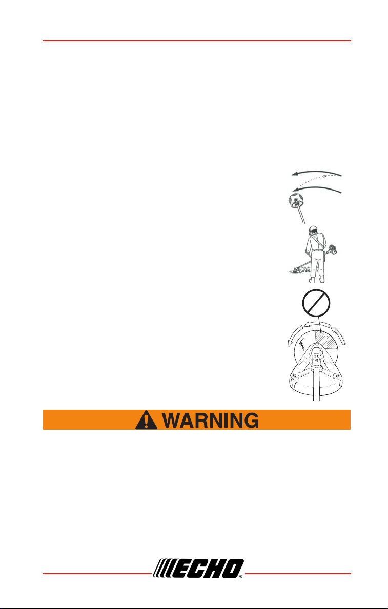
• Do not swing the main pipe with arms. Turn hips to
swing the blade horizontally from right to left, and cut
weeds on the left side of the blade.
• Do not scythe back and forth as the grass may scatter
and kickback may occur easily.
• Tilt blade left by 5 to 10 degrees so that cut grasses will
push left, making progress easier.
• Move forward with each arc to cut a swath.
• Width of cutting swath depends on arc. Use a larger arc
for a wider swath, or a smaller arc for a narrow swath.
Suggested cutting width is about 1.5 m (4.9 ft).
• When scything large brush up to 0.5" diameter from
right to left, avoid cutting with highlighted section.
Reaction Forces
◆ The cutting attachment will continue to rotate even after
the throttle is released, maintain control of the unit until it
has come to a complete stop.
◆ Blade thrust may occur when the spinning blade contacts
an object that it does not immediately cut. Following
proper cutting techniques will prevent blade thrust.
◆ Blade thrust can be violent enough to cause the unit and/or
operator to be propelled in any direction, and possibly lose
control of the unit.
X7502341703 29
© 07/2020 ECHO Incorporated
Page 30
OPERATION SRM-2620
◆ Blade thrust can occur without warning if the blade snags,
stalls or binds.
◆ Blade thrust is more likely to occur in areas where it is
difficult to see the material being cut.
Push or Pull - Kickout
During normal use, operating a brushcutter with a circular metal blade can
produce sudden strong reaction forces that are difficult to control. Strong
reaction forces can cause a loss of balance or loss of control of the
equipment, resulting in serious injury to operator and bystanders.
Understanding what causes these reactive forces may help you to avoid
them, and can help you to maintain control of the equipment if you
experience a sudden reaction during cutting. Reactive forces occur when
the force being applied by the cutting teeth of a blade meet resistance, and
some of the cutting force is directed back toward the equipment. The
greater the cutting force or the amount of resistance, the greater the
reactive force.
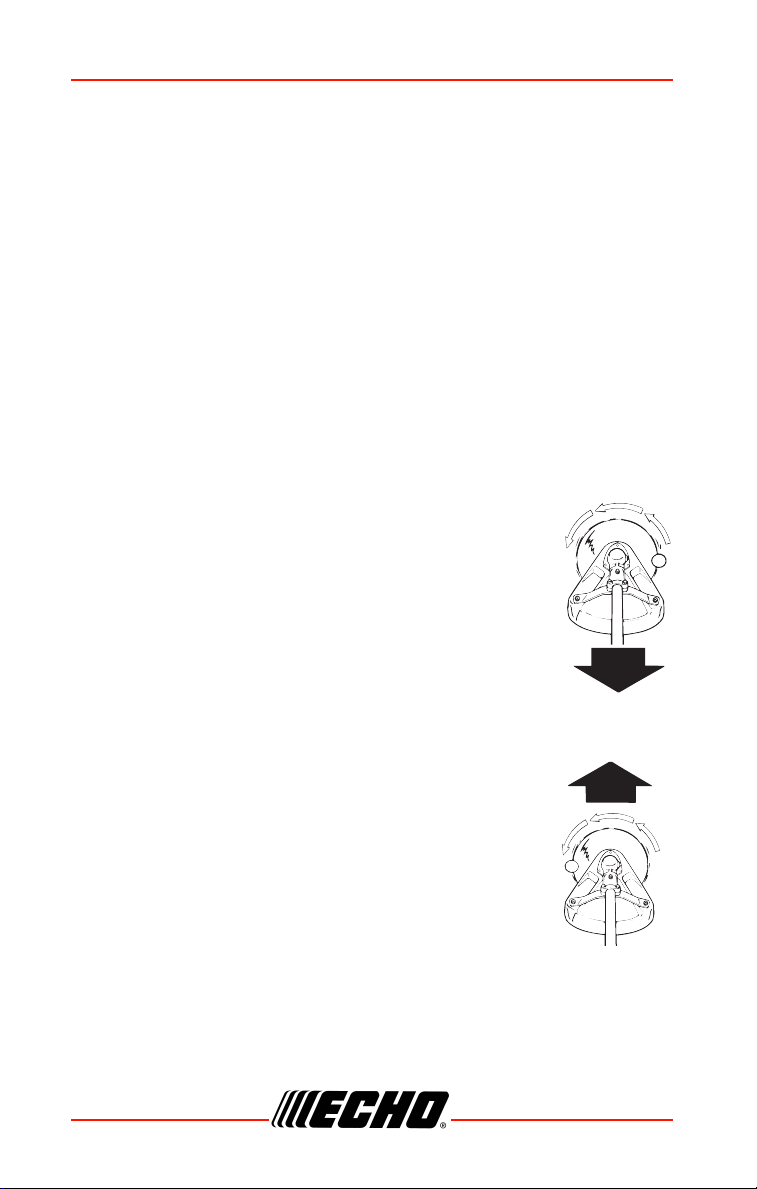
Push and Pull Forces
Push and pull forces are reactive forces that push the
equipment directly toward the operator, or that pull the
equipment directly away from the operator. These forces are
the result of cutting on the sides of the blade. The direction of
the force depends on the side of the blade being used, and
the direction of blade rotation at the point of contact. The
reactive force is in the opposite direction of blade rotation at
the contact point, regardless of where the contact is being
made. These types of reactive forces are also called “Blade
Thrust.”
As shown in the illustration, a blade turning
counterclockwise will cause the equipment to pull away
from the operator if the point of cutting resistance is on the
left side of the blade. If the point of cutting resistance is on
the right side of the blade, the equipment will push back
toward the operator. In both examples, the reactive force is
in the opposite direction of blade rotation at the contact
point where resistance occurs.
30 X7502341703
© 07/2020 ECHO Incorporated
Page 31
SRM-2620
Kickout
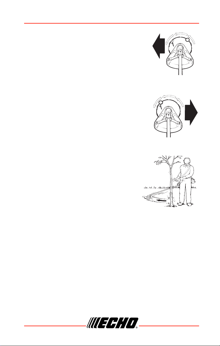
Kickout is also a reactive force caused by resistance
to cutting, but the direction of blade thrust is lateral (to
the left or right of the blade), instead of forward or
back toward the operator. In most cases, Push, Pull,
and Kickout can be reduced or eliminated by:
• Using the correct blade for the cutting job
• Using properly sharpened blades
• Applying consistent, even force to the blade during
the cut
• Avoiding obstacles and ground hazards
• Using extra care when cutting harder materials
such as extremely dry brush, saplings, and small
trees
• Cutting from a stable, secure position
Blade Cutting Problems
Binding - Blades may bind in the cut if dull or
forced. Binding can damage blade, and result in
blade breakage or injury from fragments and
flying debris. If a blade binds in a cut, don’t try to
get it out by applying “up and down” force to pry
the cut open. Applying prying force to the blade
can bend the blade, and result in blade failure
and injury.
To free a blade that is bound in the cut, stop the engine, and support the
trimmer or brushcutter to keep stress off the blade. Push the tree away from
the entry point of the cut to open the cut, and pull the blade directly away
from the cut in a straight-line motion. Use caution when releasing the tree to
avoid being struck by spring-back or falling.
Inspect the blade for damage before proceeding. Sharpen teeth if dull, or
replace blade if cracked, bent, missing teeth, or otherwise damaged.
To prevent binding:
• Keep blades sharp
• Avoid excessive pressure during cuts
• Don’t exceed cutting capacity of blade
• Don’t use blades with damaged or missing cutting teeth
X7502341703 31
© 07/2020 ECHO Incorporated
Page 32
MAINTENANCE SRM-2620
• Don’t rock blades in cut
MAINTENANCE
Moving parts can amputate fingers or cause severe injuries.
Keep hands, clothing and loose objects away from all openings.
Always stop engine, disconnect spark plug, and make sure all
moving parts have come to a complete stop before removing
obstructions, clearing debris, or servicing unit. Allow unit to
cool before performing service. Wear gloves to protect hands
from sharp edges and hot surfaces.
Operating a poorly maintained unit can result in serious injuries
to operator or bystanders. Always follow all maintenance
instructions as written, otherwise serious personal injury can
result.
Your unit is designed to provide many hours of trouble free service. Regular
scheduled maintenance will help your unit achieve that goal. If you are
unsure or are not equipped with the necessary tools, we recommend that
you take your unit to a Servicing Dealer for maintenance. To help you
decide whether you want to DO-IT-YOURSELF or have the Dealer do it,
each maintenance task has been graded. If the task is not listed, see your
Dealer for repairs.
The use of emission control components other than those specifically
designed for this unit is a violation of federal law.
Skill Levels
Level 1 = Easy to do. Common tools may be required.
Level 2 = Moderate difficulty. Some specialized tools may be required.
Level 3 = See your dealer.
Click HERE or go to http://www.echo-usa.com/products/maintenance-kit
or
32 X7502341703
© 07/2020 ECHO Incorporated
Page 33
SRM-2620
HERE https://www.shindaiwa-usa.com/you-can.aspx
For information about maintenance kits.
Maintenance Intervals
COMPONENT/SYSTEM
MAINTENANCE
PROCEDURE
SKILL
LEVEL
Daily or Before Use
Air Filter
Choke Shutter
Fuel System
Cooling System
Recoil Starter Rope
Screws/Nuts/Bolts
Inspect/Clean *
3
Inspect
Inspect/Clean 2
Inspect/Clean *
Inspect/Tighten/Replace *
1
1
Blade Inspect/Replace * 1
Every Refuel
Fuel System
Inspect
3
1
3 Months
Air Filter
Fuel Filter
Fuel Cap Gasket
Replace *
Inspect *
1
Spark Plug
Muffler Spark Arrestor
Cylinder Exhaust Port
Drive Shaft (Flex Cable Models)
Gear Housing (Some Models)
Inspect/Clean/Replace *
Inspect/Clean/De-carbon
1
Grease
2
Grease
2
Yearly
Fuel Filter
Fuel Cap Gasket
Inspect/Replace *
Replace *
1
IMPORTANT NOTE - Time intervals shown are maximum. Actual use and
your experience will determine the frequency of required maintenance.
MAINTENANCE PROCEDURE NOTES:
1
Apply lithium based grease every 25 hours of use.
2
Apply lithium based grease every 50 hours of use.
X7502341703 33
© 07/2020 ECHO Incorporated
Page 34
MAINTENANCE SRM-2620
A
B
C
3
Low evaporative fuel tanks DO NOT require regular maintenance to
maintain emission integrity.
* Replacement is recommended based on the finding of damage or wear
during inspection.
Air Filter
Level 1
Parts Required: Tune Up Kit.
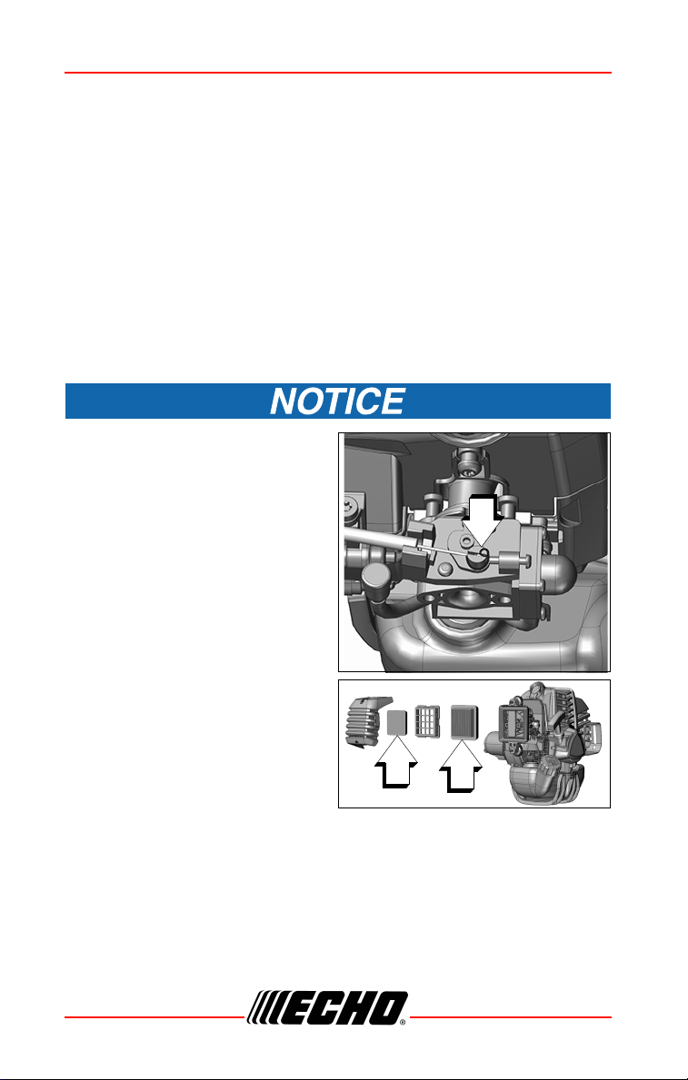
1. Close choke (COLD START position). This prevents dirt from entering
the carburetor throat when the air filter is removed. Brush accumulated
dirt from air cleaner area.
2. Remove air filter cover. Brush dirt from inside cover.
Assure throttle wire retaining clip
(A) remains in place as shown
when removing or installing air
filter cover.
3. Remove foam pre-filter (B) and
air filter (C) and clean as
indicated below:
4. Foam Pre-filter.
• Clean foam filter in water/
detergent solution and rinse
with clean water.
• Wrap the filter in a clean, dry cloth and squeeze (do not wring) dry.
Allow to dry completely before reuse. Do not oil.
Air Filter
• Lightly brush debris from filter. Replace filter if it is damaged, fuel
soaked, very dirty, or the rubber sealing edges are deformed.
5. Assemble components in reverse order.
34 X7502341703
© 07/2020 ECHO Incorporated
Page 35
SRM-2620
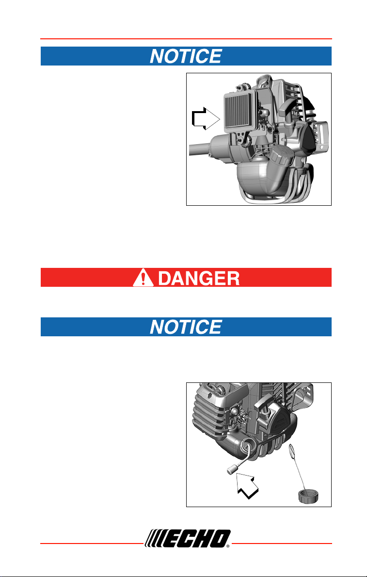
Assure air filter is assembled
with pleats oriented vertically.
Fuel Filter
Level 1.
Parts Required: Tune Up Kit.
Fuel is VERY flammable. Use extreme care when mixing, storing
or handling, or serious personal injury may result.
Do not damage fuel line while removing Fuel Filter from tank.
1. Use a clean rag to remove loose dirt from around fuel cap and empty
fuel tank.
2. Pull fuel filter out through gas
port, and inspect fuel filter.
3. When the fuel filter is dirty,
replace it as follows:
a. Do not remove the wire coil
clamp to remove the fuel
filter. Pinch the fuel filter
with the fingers on one
hand and the fuel line with
the other hand. Pull and
twist slightly to separate.
b. Install the new fuel filter
with the reverse action.
X7502341703 35
© 07/2020 ECHO Incorporated
Page 36
MAINTENANCE SRM-2620
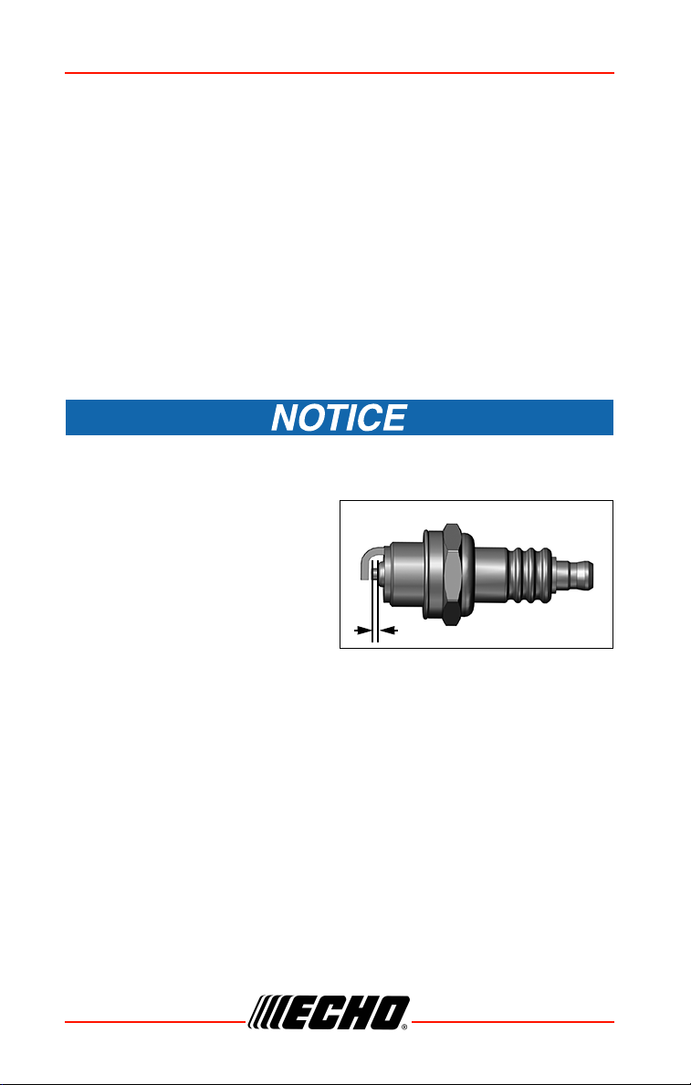
0.65 mm (0.026 in.)
c. When the inside of the fuel tank is dirty, rinse the tank out with
gasoline to clean it.
Note: Federal EPA regulations require all model year 2012 and
later gasoline powered engines produced for sale in the
United States to be equipped with a special low permeation
fuel supply hose between the carburetor and fuel tank. When
servicing model year 2012 and later equipment, only fuel
supply hoses certified by EPA can be used to replace the
original equipment supply hose. Fines up to $37,500 may be
enforced for using an un-certified replacement part.
Spark Plug
Level 2.
Parts Required: Tune Up Kit.
Use only NGK CMR7H spark plug otherwise severe engine damage
may occur.
1. Remove spark plug and check
for fouling, worn and rounded
center electrode.
2. Clean the plug or replace with a
new one. DO NOT sand blast to
clean. Remaining sand will
damage engine.
3. Adjust spark plug gap by
bending outer electrode.
4. Tighten spark plug to 102- 153 kgf•cm (89 - 133 in•lbf).
Cooling System
Level 2.
36 X7502341703
© 07/2020 ECHO Incorporated
Page 37
SRM-2620
A
B
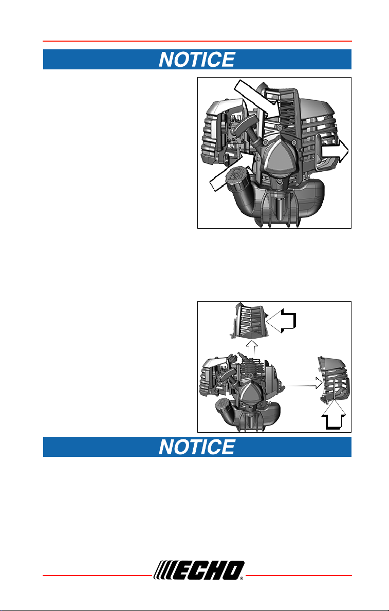
To maintain proper engine
operating temperatures, cooling
air must pass freely through the
cylinder fin area. This flow of air
carries combustion heat away
from the engine.
Overheating and engine seizure can
occur when:
• Air intakes are blocked,
preventing cooling air from
reaching the cylinder.
• Dust and grass build up on the
outside of the cylinder. This build
up insulates the engine and prevents the heat from leaving.
Removal of cooling passage blockages or cleaning of cooling fins is
considered “Normal Maintenance”. Any failure attributed to lack of
maintenance is not covered by the warranty.
1. Remove spark plug lead.
2. Remove muffler cover (A).
3. Remove engine cover (B).
DO NOT use a metal scraper to remove dirt from the cylinder fins.
X7502341703 37
© 07/2020 ECHO Incorporated
Page 38
MAINTENANCE SRM-2620
C
A
B
C
D
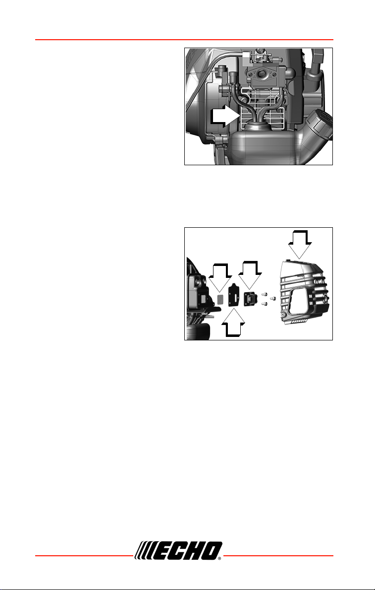
4. Use brush to remove dirt from
the cylinder fins.
5. Remove grass and leaves from
the grid (C) between the recoil
starter and fuel tank.
6. Assemble components in
reverse order.
Exhaust System
Spark Arrestor Screen
Level 2.
Parts Required: Spark Arrestor Screen, Gasket
1. Remove spark plug lead.
2. Remove muffler cover (A).
3. Place piston at Top Dead
Center (TDC) to prevent carbon
or dirt from entering cylinder.
4. Remove spark arrestor screen
cover (B), gasket (C), and
screen (D), from muffler body.
5. Clean carbon deposits from
muffler components.
Note: When cleaning carbon deposit, be careful not to damage the
catalytic element inside muffler.
6. Replace screen if it is cracked, plugged, or has holes burned through.
7. Assemble components in reverse order.
Exhaust Port Cleaning
Level 2.
Parts Required: Heat Shield (as needed)
38 X7502341703
© 07/2020 ECHO Incorporated
Page 39
SRM-2620
B
A
C
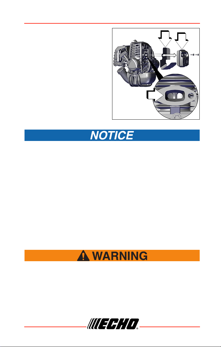
1. Remove spark plug lead from
spark plug, and remove muffler
cover.
2. Place piston at top dead center.
Remove muffler (A) and heat
shield (B).
3. Use a wood or plastic scraping
tool to clean deposits from
cylinder exhaust port (C).
Never use a metal tool to scrape carbon from the exhaust port. Do
not scratch the cylinder or piston when cleaning the exhaust port. Do
not allow carbon particles to enter the cylinder.
4. Inspect heat shield, and replace if damaged.
5. Install heat shield and muffler.
6. Tighten muffler mounting bolts (or nuts) to 90- 110 kgf•cm (80- 95
in•lbf).
7. Install muffler cover and attach spark plug lead.
8. Start engine, and warm to operating temperature.
9. Stop engine, and re-tighten mounting bolts (or nuts) to specifications.
Carburetor Adjustment
Level 2.
When carburetor adjustment is completed, the cutting
attachment should not move at idle, otherwise serious personal
injury may result.
X7502341703 39
© 07/2020 ECHO Incorporated
Page 40

MAINTENANCE SRM-2620
Engine Break-In
New engines must be operated a minimum duration of two tanks of fuel
break-in before carburetor adjustments can be made. During the break-in
period your engine performance will increase and exhaust emissions will
stabilize. Idle speed can be adjusted as required.
High Altitude Operation
This engine has been factory adjusted to maintain satisfactory starting and
durability performance up to 330 m (1100 ft.) above sea level (ASL) (96.0
kPa). To maintain proper engine operation above 330 m (1100 ft.) ASL the
carburetor may
If the engine is adjusted for operation above 330 m (1100 ft.) ASL, the
carburetor must be re-adjusted when operating the engine below
330 m (1100 ft.) ASL, otherwise severe engine damage may result.
Note: Every unit is run at the factory and the carburetor is set in
compliance with emission regulations. Carburetor
adjustments, other than idle speed, must be performed by an
authorized dealer.
◆ The cutting attachment may be moving during carburetor
adjustments.
◆ Wear your protective equipment and observe all safety
instructions.
◆ For units equipped with a clutch, be sure the cutting
attachment stops moving when the engine idles.
◆ When the unit is turned off, make sure the cutting
attachment has stopped before the unit is set down.
need to be adjusted by an authorized service dealer.
40 X7502341703
© 07/2020 ECHO Incorporated
Page 41
SRM-2620
A
A
A
B
C
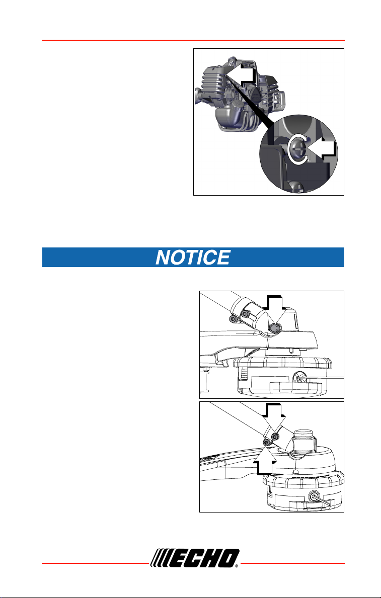
1. Check idle speed and reset if
necessary. If a tachometer is
available, idle speed screw (A)
should be set to the
specifications found on
“Specifications” page of this
manual. Turn idle screw (A)
clockwise to increase idle
speed; counterclockwise to
decrease idle speed.
Lubrication
Level 1.
Parts Required: Lithium Based
Grease.
Gear Case
Gear cases without grease plug (A) do not require lubrication.
1. Clean all loose debris from gear
case.
2. Remove plug (A) and check level
of grease.
3. Add grease if necessary. DO
NOT over-fill.
Drive Shaft (flex cable only)
1. Loosen screw (B) and remove
locating screw (C). Pull gear
case and shield from drive shaft
housing.
X7502341703 41
© 07/2020 ECHO Incorporated
Page 42
MAINTENANCE SRM-2620
D
B
A
C
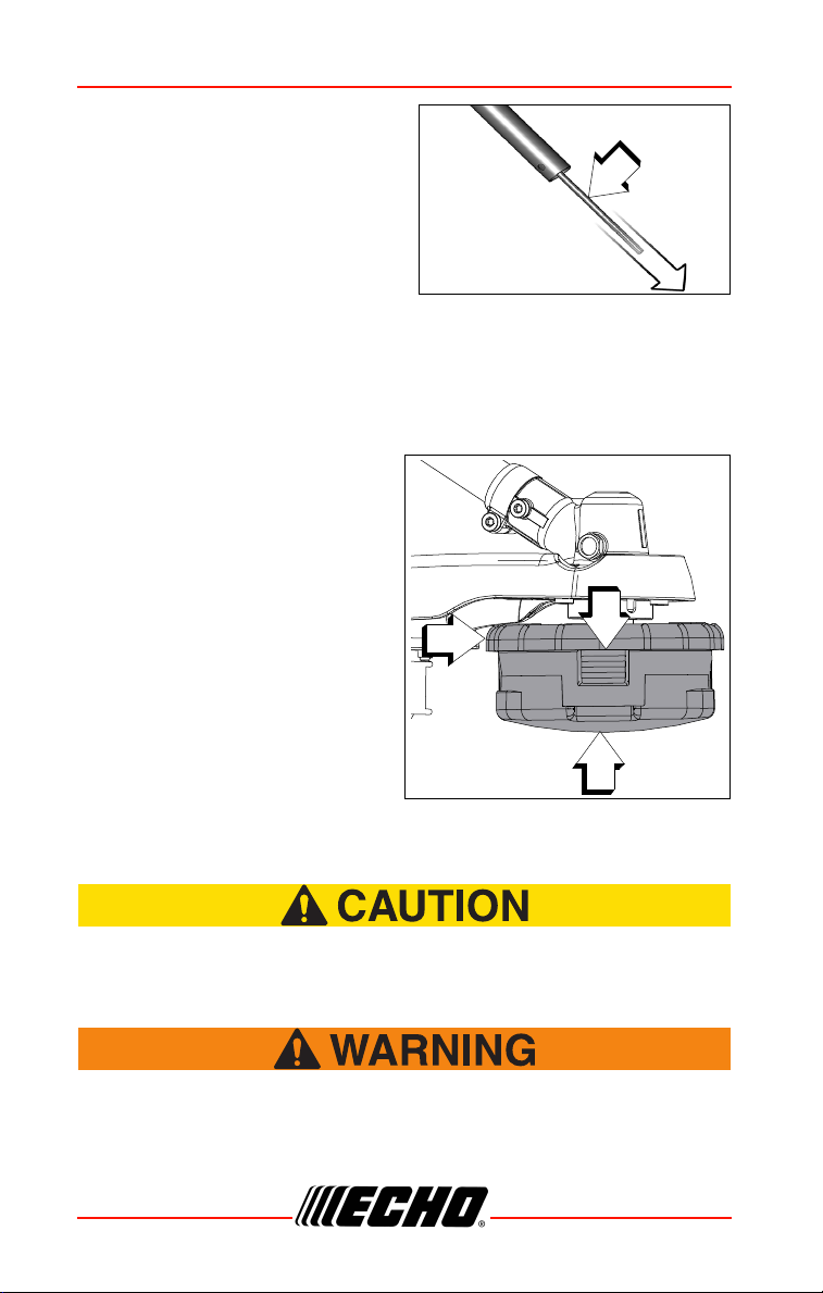
2. Pull flexible cable (D) from the
drive shaft housing, wipe clean
and re-coat with 15 ml (0.5 oz.) of
grease.
3. Slide the flexible cable (D) back
in the drive housing. DO NOT get
dirt on the flex cable.
4. Install the gear housing and
shield assembly.
Nylon Line Head Disassembly Instructions
Note: For normal use, Speed Feed® head disassembly is not
necessary. However, if circumstances require disassembly,
follow these instructions.
1. Press top of locking tabs (A) on
both sides of Speed Feed®
head to release cover (B) from
eyelet carrier (C).
2. Remove cover from eyelet
carrier.
Nylon Line Replacement
Wear gloves or personal injury may result:
◆ Cutoff knife is sharp.
◆ Gearcase and surrounding area may be hot.
Never use wire or wire-rope that can break off and become a
dangerous “projectile”. Serious injury can occur.
42 X7502341703
© 07/2020 ECHO Incorporated
Page 43
SRM-2620
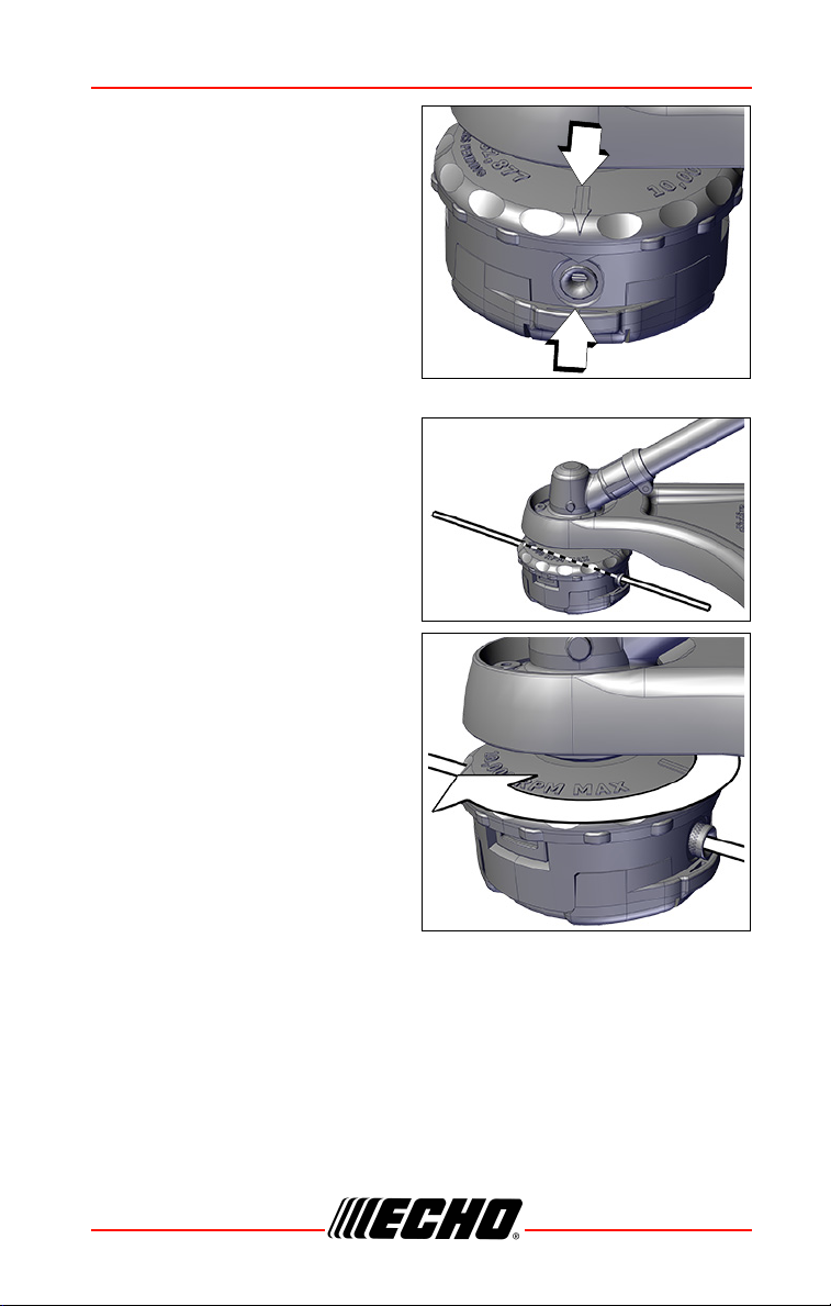
1. Cut one piece of line to
recommended length.
2.0 mm (0.080 in.) diameter
6 m (20 ft.).
2.4 mm (0.095 in.) diameter
6 m (20 ft.).
2. Align arrows on top of knob with
openings in eyelets.
3. Insert one end of trimmer line
into an eyelet, and push line
equal distance through trimmer
head.
4. Hold trimmer head while turning
knob clockwise to wind line
onto spool until about 13 cm
(5 in.) of each line remains
exposed.
Trimmer head is now fully loaded
and ready for operation.
X7502341703 43
© 07/2020 ECHO Incorporated
Page 44
MAINTENANCE SRM-2620
30º
30º
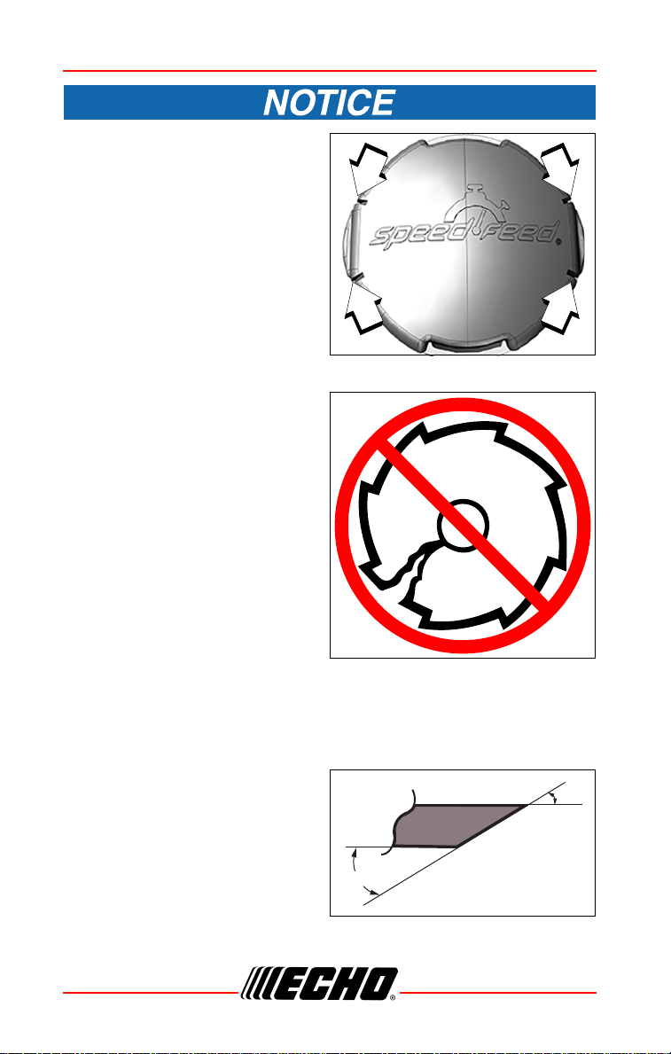
When the wear indicators
located at the bottom of the
Speed-Feed® head are worn
smooth, or if holes appear,
replacement of the cover or the
entire Speed-Feed® head is
required.
Sharpening Metal Blades
Several styles of metal blades are
approved for use on the
Brushcutter. The 8-tooth blade can
be sharpened during normal
maintenance. The clearing blade
and 80-tooth blade require
professional service.
Before sharpening, CLOSELY
inspect blade for cracks (look at the
bottom of each tooth and the center
mounting hole closely), missing
teeth and bending. If ANY of these
problems are discovered, replace
the blade.
When sharpening a blade, always remove the same amount of materials
from each tooth to maintain balance. A blade that is not balanced will cause
unsafe handling due to vibration and can result in blade failure.
1. File each tooth at a 30° angle a
specific number of times, e.g.,
four strokes per tooth. Work
your way around the blade until
all teeth are sharp.
2. DO NOT file the ‘gullet’ (radius)
of the tooth with the flat file. The
radius must remain. A sharp
corner will lead to a crack and
blade failure.
44 X7502341703
© 07/2020 ECHO Incorporated
Page 45
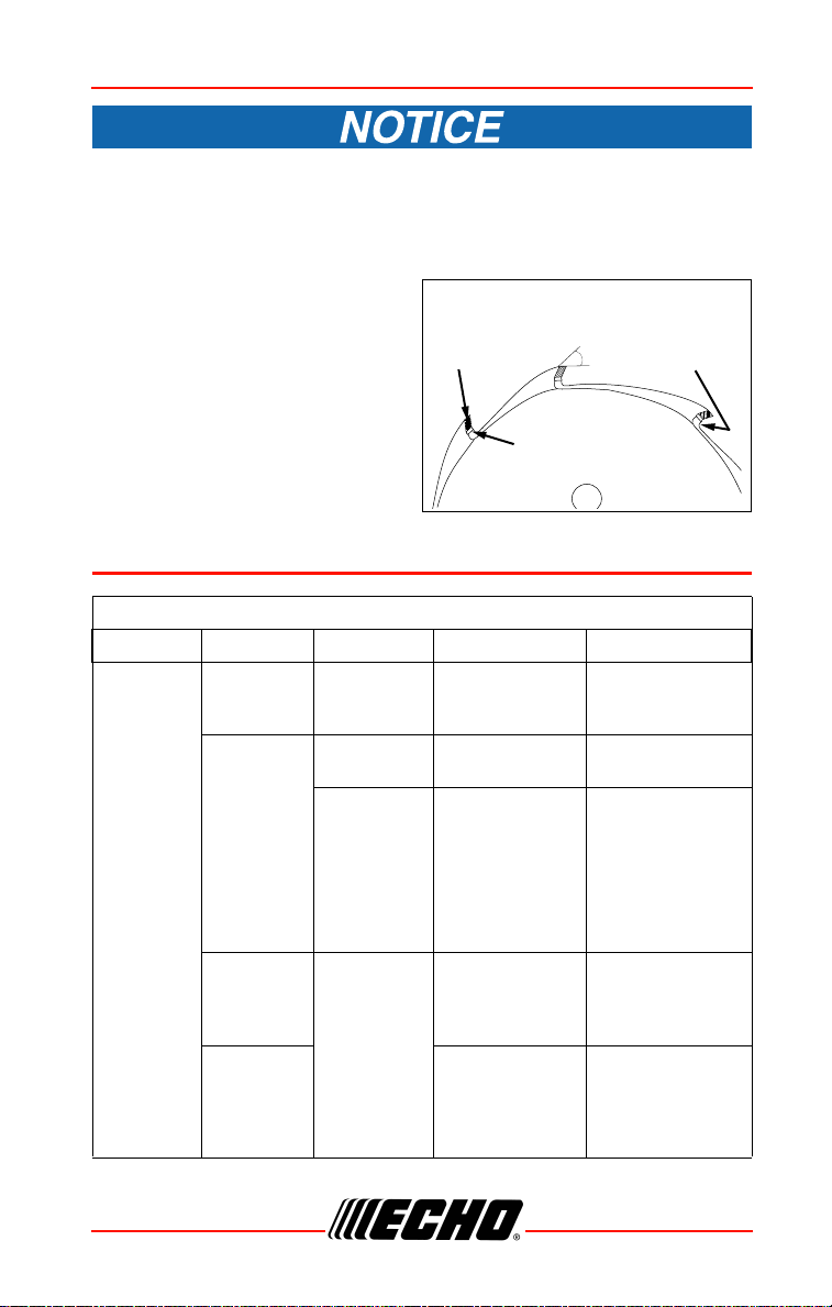
30º
CUTTING
TOOTH
AREA
CUTTING
TOOTH
RADIUS
GULLET
(RADIUS)
SRM-2620
If an electric grinder is used, use care not to overheat teeth, do not
allow tips/tooth to glow red or turn blue. DO NOT place blade in
cooling water. This will change the temper of the blade and could
result in blade failure.
3. After sharpening teeth, check
each tooth radius for evidence
of a square (sharp) corner. Use
the round (rat tail) file to renew
the radius.
TROUBLESHOOTING
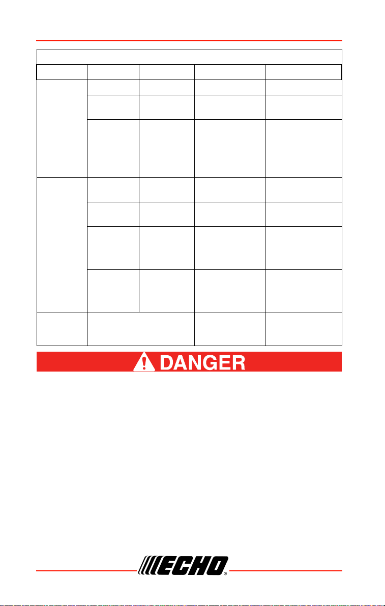
ENGINE PROBLEM TROUBLESHOOTING CHART
Problem Check Status Cause Remedy
Engine
starts hard
or
Engine
does not
start
Fuel at
carburetor
Fuel at
cylinder
Spark at
end of plug
wire
Spark at
plug
No fuel at
carburetor
No fuel at
cylinder
Muffler wet
with fuel
No spark
Fuel strainer or
fuel line
obstructed
Carburetor See your dealer
Fuel mixture too
rich
STOP switch
OFF - Electrical
problem Interlock switch
Incorrect gap Covered with
carbon - Fouled
with fuel - Plug
defective
Clean or replace
See your dealer
OPEN choke
Clean or replace
air filter
Adjust carburetor
See your dealer
Turn switch to
ON
See your dealer
Adjust to 0.65mm
(0.026 in.)
Clean or replace
plug
X7502341703 45
© 07/2020 ECHO Incorporated
Page 46
TROUBLESHOOTING SRM-2620
ENGINE PROBLEM TROUBLESHOOTING CHART
Problem Check Status Cause Remedy
Engine
runs, but
dies
or
Air filter Air filter dirty Normal wear Clean or replace
Fuel filter
Fuel filter
dirty
Contaminants
or residue in fuel
Replace filter or
replace fuel
Engine
does not
accelerate
properly
Engine
runs, but
dies
or
Engine
does not
accelerate
properly
Engine
does not
crank
Fuel vent
Spark plug
Carburetor
Cooling
system
Spark
arrestor
screen
Fuel vent
plugged
Plug dirty or
worn
Improper
adjustment
Cooling
system dirty
or plugged
Spark
arrestor
screen
plugged
N/A
Contaminated
fuel
Normal wear
Vibration Adjust
Extended
operation in
dirty or dusty
locations
Normal wear Replace
Internal engine
problem
Clean or replace
Clean and adjust
or replace
Clean
See your dealer
Fuel vapors are extremely flammable and can cause fire and/or
explosion. Never test for ignition spark by grounding spark plug
near cylinder plug hole, otherwise serious personal injury can
result.
46 X7502341703
© 07/2020 ECHO Incorporated
Page 47
SRM-2620
STORAGE
During operation the muffler or catalytic muffler and
surrounding cover become hot. Always keep exhaust area clear
of flammable debris during transportation or when storing,
otherwise serious property damage or personal injury may
result.
Long Term Storage (Over 30 Days)
Do not store your unit for a prolonged period of time (30 days or longer)
without performing protective storage maintenance which includes the
following:
1. Store unit in a dry, dust free place, out of the reach of children.
Do not store in enclosure where fuel fumes may accumulate or
reach an open flame or spark.
2. Place the stop switch in the “OFF” position.
3. Remove accumulation of grease, oil, dirt and debris from exterior of
unit.
4. Perform all periodic lubrication and services that are required.
5. Tighten all the screws and nuts.
6. Drain fuel tank completely. Press purge bulb 6-7 times to remove
remaining fuel from carburetor then drain the tank again. Close choke,
start and run the engine until it stops due to lack of fuel.
7. Allow engine to cool. Remove the spark plug lead from the spark plug.
Remove the spark plug. Pour 7 cc (0.25 oz.) of fresh, clean, two-stroke
engine oil into the cylinder through the spark plug hole.
8. Pull the recoil starter handle 2-3 times to distribute the oil inside the
engine.
9. Observe the piston location through the spark plug hole. Pull the recoil
handle slowly until the piston reaches the top of its travel and leave it
there.
10. Install the spark plug. Connect the spark plug lead to the spark plug.
X7502341703 47
© 07/2020 ECHO Incorporated
Page 48
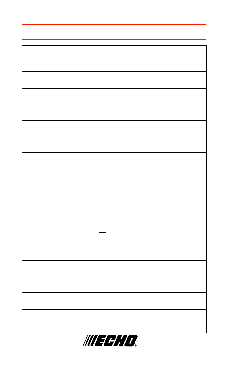
SPECIFICATIONS SRM-2620
SPECIFICATIONS
MODEL SRM-2620
Length w/o cutter head 1799 mm (70.8 in.)
Width 273mm (10.7 in.)
Height 336mm (13.2 in.)
Weight (dry) w/o cutter head 5.1 kg (11.2 lb.)
Engine Type
Bore 34 mm (1.34 in.)
Stroke 28 mm (1.10 in.)
Displacement 25.4cc (1.55 cu. in.)
Exhaust
Carburetor Diaphragm w/purge pump
Ignition System
Spark Plug NGKCMR7H Gap 0.6 mm (0.026 in.)
Fuel Mixed (Gasoline and Two-stroke Oil)
Gasoline/Oil Ratio 50 : 1
Gasoline
Oil
Fuel Tank Capacity 0.61 L (20.6 US fl. oz.)
Starter System Automatic Rewind Starter
Clutch Centrifugal Type
Vibration Isolated System
Operating Rod 25.0 mm aluminum Tube
Drive Shaft 6.15 mm flexible shaft (.24 in)
Gear Case Ratio 1.62 Reduction
Rotating Direction Counterclockwise; viewed from top
Cutter Head
Handle Front - loop, Rear handle
Air cooled, two-stroke, single cylinder gasoline
engine
Spark arrestor muffler or spark arrestor muffler
with catalyst
Flywheel magneto, capacitor discharge ignition
type
Use 89 Octane unleaded. Do not use fuel
containing methyl alcohol, more than 10% ethyl
alcohol or 15% MTBE. Do not use alternative
fuels such as E15 or E85.
ISO-L-EGD (ISO/CD 13738) and J.A.S.O. M345FD
, two-stroke, air-cooled engine oil.
Rubber cushion on engine mount (heavy duty).
Rubber grip on front handle.
®
Speed Feed
capacity 6.0 m (20 ft.)
400 LH Nylon line head, Line
48 X7502341703
© 07/2020 ECHO Incorporated
Page 49

SRM-2620
MODEL SRM-2620
Shoulder Harness Optional
Idle Speed 3,000 RPM
Clutch Engagement Speed 4,100 RPM
Wide Open Throttle Speed
(W.O.T.)
10,300 RPM
X7502341703 49
© 07/2020 ECHO Incorporated
Page 50

PRODUCT REGISTRATION SRM-2620
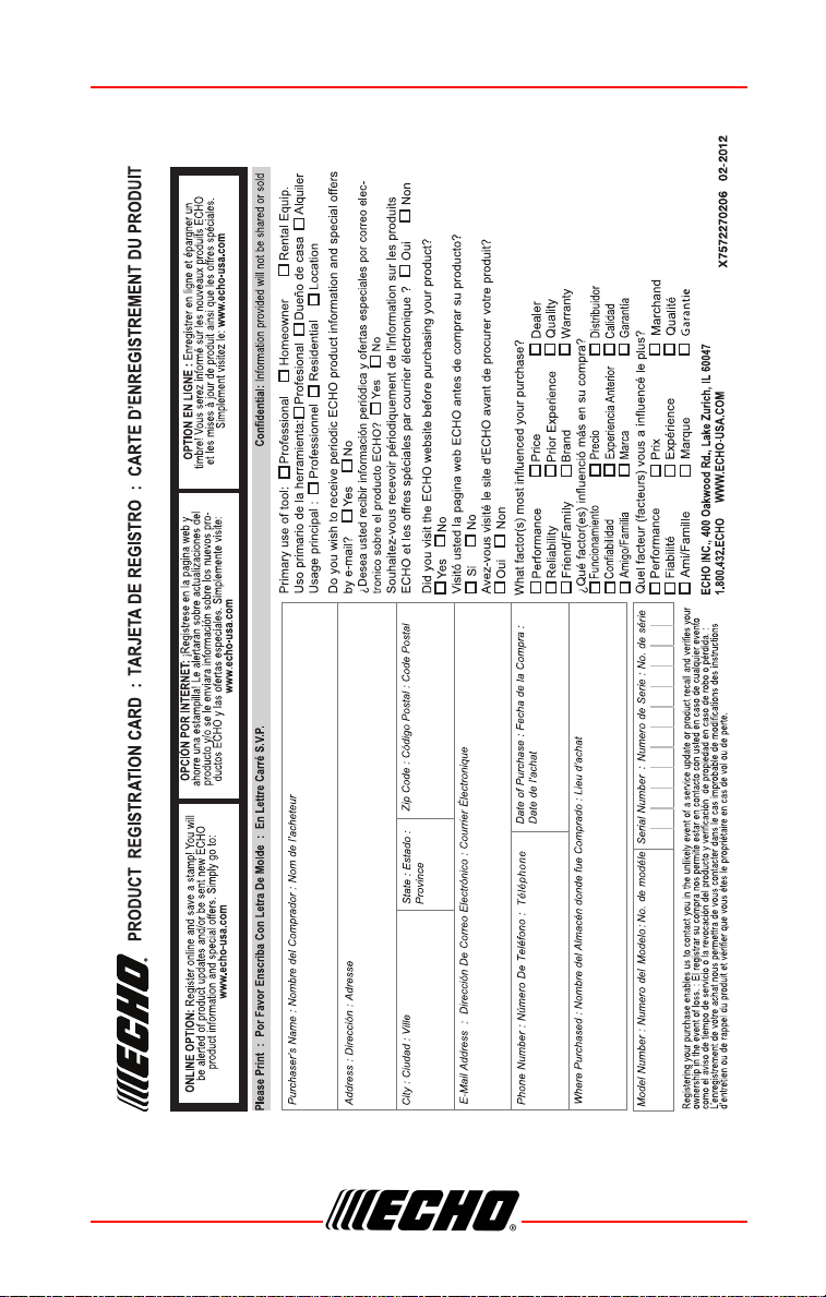
PRODUCT REGISTRATION
Thank you for choosing ECHO Power Equipment
Please go to http://www.echo-usa.com/Warranty/Register-Your-ECHO to
register your new product on-line. It's FAST and EASY! NOTE: your
information will never be sold or misused by ECHO, Incorporated.
Registering your purchase enables us to contact you in the unlikely event of
a service update or product recall, and verifies your ownership for warranty
consideration.
If you do not have access to the Internet, you can complete the form below
and mail to:
ECHO Incorporated, Product Registration, PO Box 1139, Lake Zurich
IL 60047.
50 X7502341703
© 07/2020 ECHO Incorporated
Page 51
SRM-2620
X7502341703 51
© 07/2020 ECHO Incorporated
Page 52

T94215001001 - T94215999999
U42615001001 - U42615999999
ECHO INCORPORATED
400 Oakwood Road
Lake Zurich, IL 60047
www.echo-usa.com
 Loading...