

Page 1
Grass Trimmer/Brush Cutter
Operator's Manual
MODELS SRM - 260
SRM - 260S
Serial Number 03001001 - 03999999
X7502095601
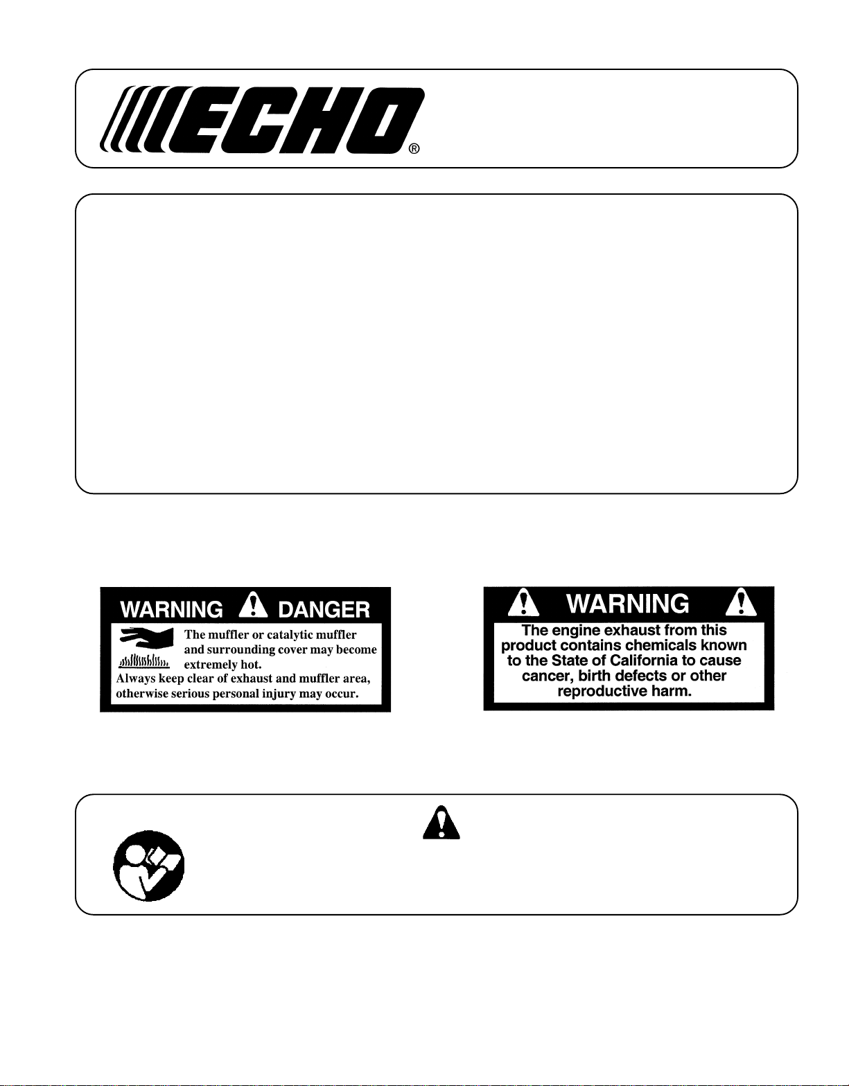
W ARNING DANGER
Read rules for safe operation and instructions carefully. ECHO provides an
Operator's Manual and a Safety Manual. Both must be read and understood for
proper and safe operation. Failure to do so could result in serous injury.
X750001841
07/01
Page 2
Page 3
GRASS TRIMMER/BRUSH CUTTER
OPERATOR'S MANUAL
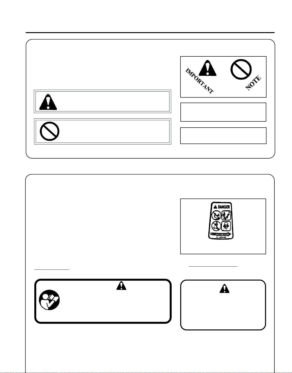
MANUAL SAFETY SYMBOLS AND IMPORTANT INFORMATION
Throughout this manual and on the product itself, you will find safety
alerts and helpful, information messages preceded by symbols or key
words. The following is an explanation of those symbols and key words
and what they mean to you.
This symbol accompanied by the words WARNING and
DANGER calls attention to an act or condition that can lead
to serious personal injury to operator and bystanders.
The circle with the slash symbol means whatever is shown
within the circle is prohibited.
IMPORTANT The enclosed message
provides information necessary for the
protection of the unit.
NOTE This enclosed message provides tips for
use, care and maintenance of the unit.
3
SAFETY
DECALS
Locate these safety decals on your unit. The complete unit illustration,
found in the "DESCRIPTION" section, will help you locate them. Make
sure the decals are legible and that you understand and follow the
instructions on them. If a decal cannot be read, a new one can be
ordered from your ECHO dealer. See PARTS ORDERING instructions
for specific information.
Shaft Decal
Spanish Decal
ADVERTENCIA PELIGRO
Esta unidad puede ser peligrosa y producir lesiones
personales graves si no se usa en forma adecuada.
Para reducir el riesgo de lesionarse, los operadores,
los ayudantes y los espectadores deben leer y
89017740630
comprender el Manual Del Operador y los Manuales
De Seguridad que se entregan escritos en español.
Debris Shield Decal
Metal Debris
Shield
English Translation
WARNING DANGER
This unit can be dangerous and cause
serious injury if improperly used. To
reduce injury risk to operator, helpers
and bystanders, read and understand
the Operator's and Safety Manuals,
which are provided in Spanish.
Page 4
4
Shaft Decal
W ARNING DANGER
• This unit can be dangerous and cause serious injury if improperly
used. To reduce injury risk to operator, helpers and bystanders, read
and understand the Operator's and Safety manuals.
• Blindness can occur from objects that are thrown or ricocheted even
with shield in place. Operators, helpers and bystanders must wear
ANSI Z87.1 approved eye protection.
• Always wear hearing protection when operating unit.
• Prevent accidental contact with unit and any cutting attachment.
Maintain a 15 m (50 ft.) radius, DANGER ZONE surrounding the
operator. ONLY the operator, dressed in proper protective clothing
should be in the DANGER ZONE.
• Beware of KICKOUT (blade thrust) when using blades. Special
precautions are necessary for blade operation, see your Operator's
and Safety Manuals. ONLY install ECHO approved blades on Brush
Cutters (SRM) models equipped with proper blade shield, U-handles,
harness, blade collar, nut and cotter pin.
• Blade/Cutting attachment does not stop immediately after releasing
throttle. Keep hands and feet clear of blade/cutting attachment unless
engine is shut off and cutting attachment is not moving.
• INSPECT BLADES BEFORE USE.
• DO NOT USE DAMAGED, CRACKED, BENT, DULL, OR IMPROPERLY SHARPENED BLADES.
• Do not remove shields, modify the unit or install attachments or parts
not approved by ECHO. Approved attachment information and
replacement Operator's and Safety Manuals are available from your
ECHO dealer or by writing: ECHO, INCORPORATED, 400 OAK-
WOOD RD., LAKE ZURICH, IL 60047.
P/N 89016844830
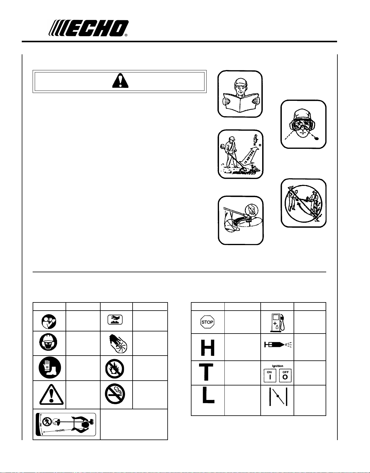
INTERNATIONAL SYMBOLS
Symbol form/shape
Symbol
description/application
"WARNING, SEE
OPERATOR'S
MANUAL
Wear eyes, ears and
head protection
Wear hand and
foot protection
Safety/Alert
Symbol form/shape
Keep bystanders and helpers
away 15 m (50 ft.).
Symbol
description/application
Hot
Surface
Finger Severing
DO NOT allow
flames or sparks
near fuel.
DO NOT smoke
near fuel.
Symbol form/shape
Symbol
description/application
Emergency stop
Carburetor adjustment
- High speed mixture
Carburetor adjustment
- Idle speed
Carburetor adjustment
- Low speed mixture
Symbol form/shape
Symbol
description/application
Fuel and oil mixture
Primer Bulb
Ignition
ON/OFF
Engine choke
control.
Page 5
GRASS TRIMMER/BRUSH CUTTER
OPERATOR'S MANUAL
SAFETY INSTRUCTIONS
PERSONAL
Trimmer/Brush Cutter users risk injury to themselves and others if the trimmer/brush cutter is used improperly and or
safety precautions are not followed. Proper clothing and safety gear must be worn when operating a trimmer.
CONDITION AND SAFETY EQUIPMENT
W ARNING DANGER
5
Physical Condition --
Your judgment and physical dexterity may not be good:
• if you are tired or sick,
• if you are taking medication,
• if you have taken alcohol or drugs.
Operate unit only if you are physically and mentally well.
Hearing Protection --
ECHO recommends wearing hearing protection whenever
unit is used.
Proper Clothing --
Wear snug fitting, durable clothing;
• Pants should have long legs, shirts with long sleeves.
• DO NOT WEAR SHORTS,
• DO NOT WEAR TIES, SCARVES, JEWELRY.
Eye Protection --
Wear eye protection that meets ANSI Z87.1 or CE
requirements whenever you operate the trimmer.
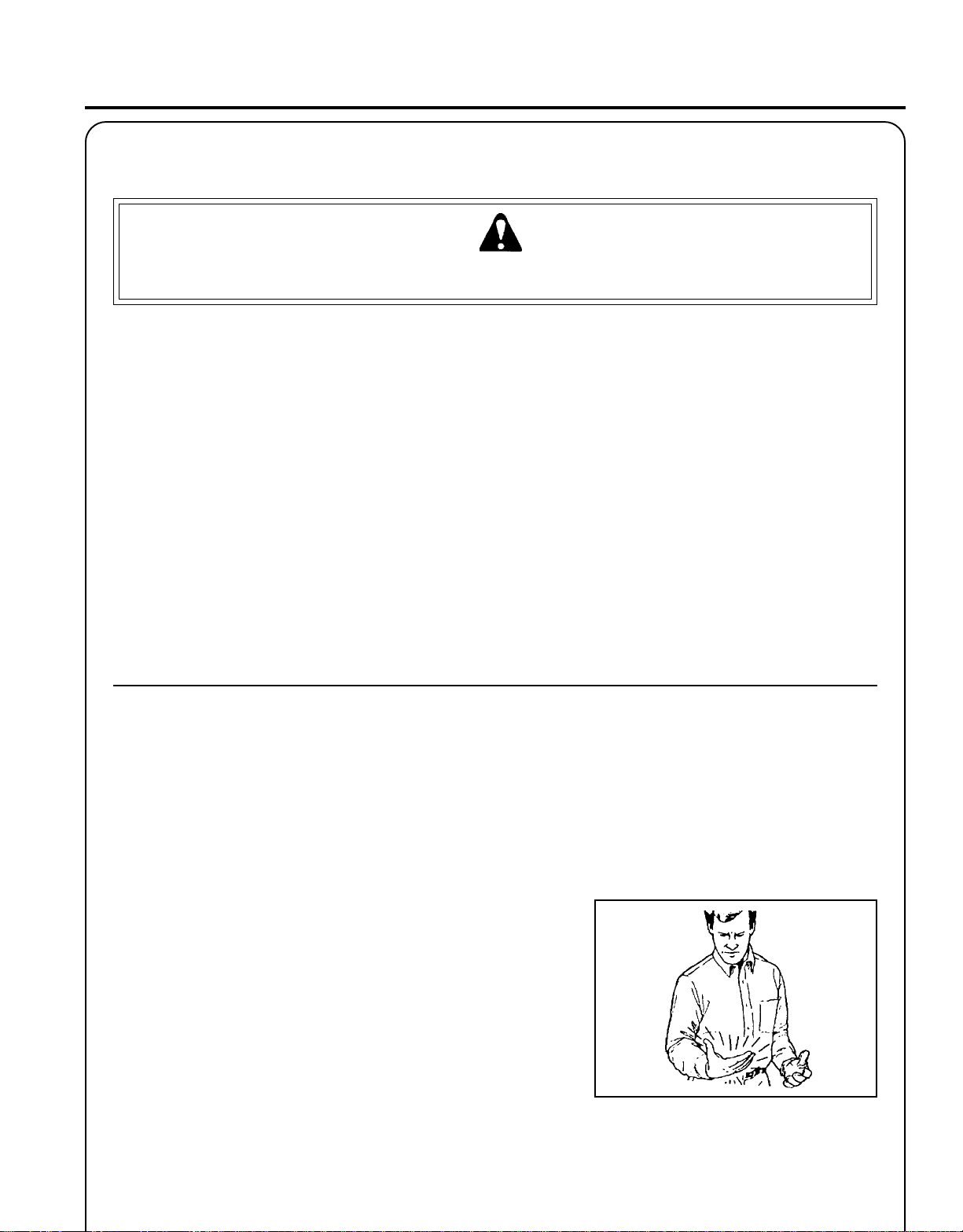
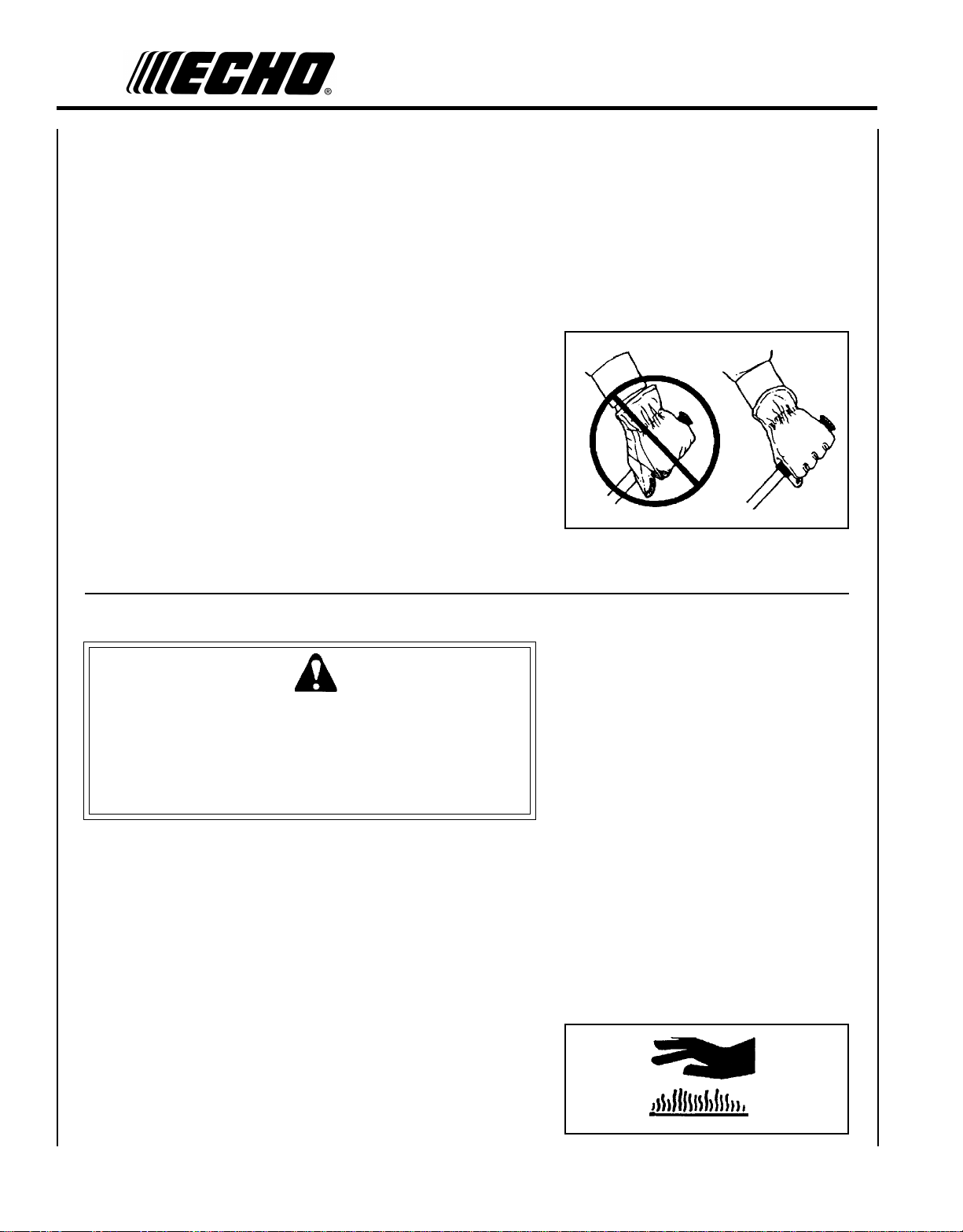
Hand Protection --
Wear no-slip, heavy duty work gloves to improve your
grip on the Trimmer/Brush Cutter handles. Gloves also
reduce the transmission of machine vibration to your
hands.
Wear sturdy work shoes with non-skid soles;
• DO NOT WEAR OPEN TOED SHOES,
• DO NOT OPERATE UNIT BAREFOOTED.
Hot Humid Weather --
Heavy protective clothing can increase operator fatigue
which may lead to heat stroke. Schedule heavy work for
early morning or late afternoon hours when temperatures
are cooler.
EXTENDED OPERATION/EXTREME CONDITIONS
Vibration and Cold
It is believed that a condition called Raynaud’s Phenomenon, which
affects the fingers of certain individuals may be brought about by
exposure to vibration and cold. Exposure to vibration and cold may
cause tingling and burning sensations followed by loss of color and
numbness in the fingers. The following precautions are strongly
recommended because the minimum exposure which might trigger the
ailment is unknown.
• Keep your body warm, especially the head, neck, feet, ankles, hands
and wrists.
• Maintain good blood circulation by performing vigorous arm exercises during frequent work breaks and also by not smoking.
• Limit the hours of operation. Try to fill each day with jobs where
operating the trimmer or other hand-held power equipment is not
required.
• If you experience discomfort, redness and swelling of the fingers
followed by whitening and loss of feeling, consult your physician
before further exposing yourself to cold and vibration.
Page 6
6
Repetitive Stress Injuries
It is believed that overusing the muscles and tendons of the fingers,
hands, arms and shoulders may cause soreness, swelling, numbness,
weakness and extreme pain in those areas. Certain repetitive hand
activities may put you at a high risk for developing a Repetitive Stress
Injury (RSI). An extreme RSI condition is Carpal Tunnel Syndrome
(CTS), which could occur when your wrist swells and squeezes a vital
nerve that runs through the area. Some believe that prolonged exposure
to vibration may contribute to CTS. CTS can cause severe pain for
months or even years.
To reduce the risk of RSI/CTS, do the following:
• Avoid using your wrist in a bent, extended or twisted position.
Instead try to maintain a straight wrist position. Also, when grasping, use your whole hand, not just the thumb and index finger.
• Take periodic breaks to minimize repetition and rest your hands.
• Reduce the speed and force with which you do the repetitive movement.
• Do exercises to strengthen the hand and arm muscles.
• Immediately stop using all power equipment and consult a doctor if
you feel tingling, numbness or pain in the fingers, hands, wrists or
arms. The sooner RSI/CTS is diagnosed, the more likely permanent
nerve and muscle damage can be prevented.
EQUIPMENT
W ARNING DANGER
Use only ECHO approved attachments. Serious injury may result
from the use of a non approved attachment combination. Read and
comply with all safety instructions listed in this manual and safety
manual. ECHO, INC. will not be responsible for the failure of
cutting devices, attachments or accessories which have not been
tested and approved by ECHO.
• Check unit for loose/missing nuts, bolts and screws. Tighten and/or
replace as needed.
• Inspect fuel lines, tank and area around carburetor for fuel leaks. DO
NOT operate unit if leaks are found.
• Inspect shield for damage and ensure that the cut-off knife is
securely in place. Replace if either is damaged or missing.
• Check that the cutting attachment is firmly attached and in safe
operating condition.
• Check that front (loop) handle and optional shoulder/waist harness
are adjusted for safe, comfortable operation. See Assembly for proper
adjustment.
• Keep exhaust area clear of flammable debris. Avoid contact during
and immediately after operation.
Page 7
GRASS TRIMMER/BRUSH CUTTER
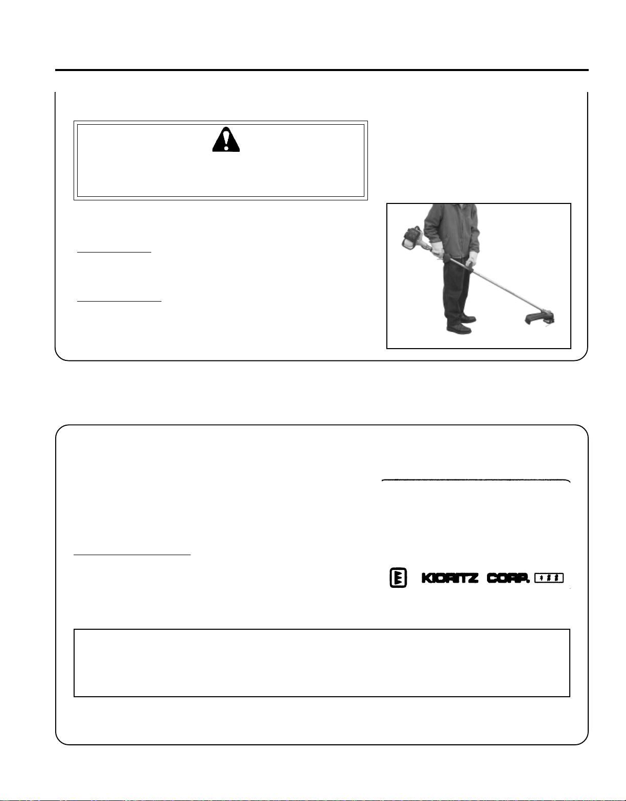
SAFE OPERATION
W ARNING DANGER
Do not operate this product indoors or in inadequately ventilated
areas. Engine exhaust contains poisonous emissions and can
cause serious injury or death.
• Provide all operators of this equipment with the Operator's Manual
and instructions for safe operation.
Keep A Firm Grip
• Hold the front and rear handles with both hands with thumbs and
fingers encircling the handles
Keep A Solid Stance
• Maintain footing and balance at all times. Do not stand on slippery,
uneven or unstable surfaces. Do not work in odd positions or on
ladders. Do not over reach.
OPERATOR'S MANUAL
7
EMISSION CONTROL
EPA Phase II
The emission control system for these engines is
EM (Engine Modification).
An Emission Control Label is located on the engine.
(This is an EXAMPLE ONLY, information on label
varies by engine FAMILY).
PRODUCT EMISSION DURABILITY
The 300 hour emission durability period is the time span selected by the manufacturer certifying the engine emissions output meets applicable California emissions regulations, provided that approved maintenance procedures are
followed as listed in the Maintenance Section of this manual.
IMPORTANT ENGINE INFORMATION
ENGINE FAMILY: YEHXS.0254CA
DISPLACEMENT: 25.4 CC
THIS ENGINE MEETS U.S. EPA PAHSE II EMISSION
REGULATIONS FOR S.O.R.E. REFER TO OWNER'S
MANUAL FOR MAINTENANCE SPECIFICATIONS AND
ADJUSTMENTS. EMISSION COMPLIANCE PERIOD :
300 HRS.
Page 8
8
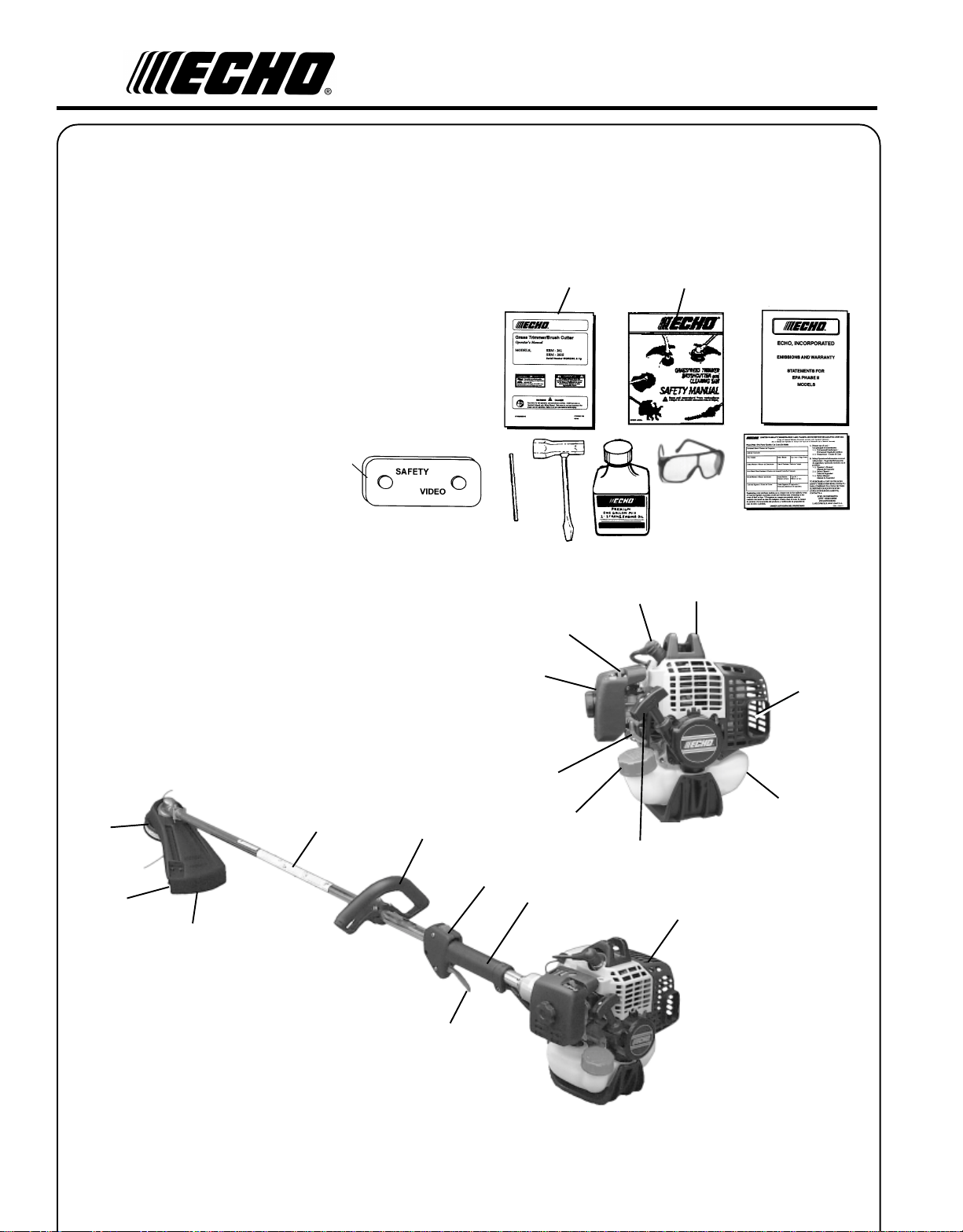
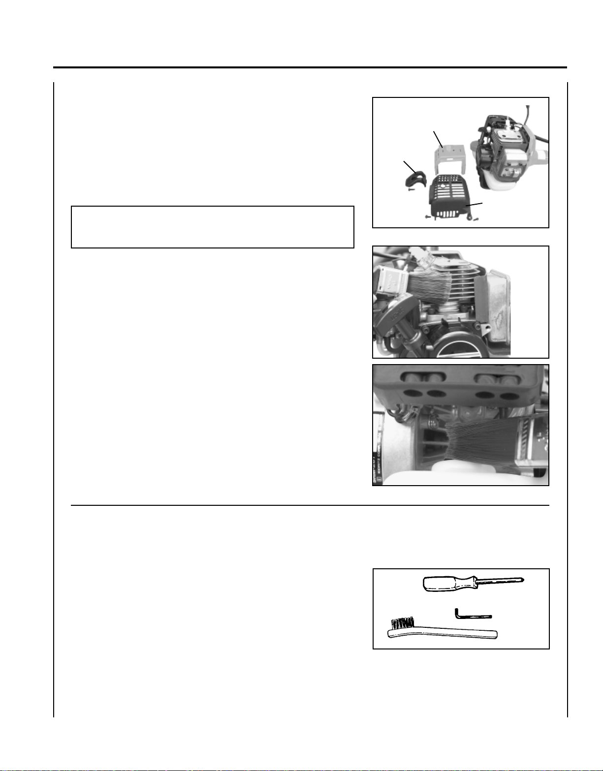
DESCRIPTION
The ECHO product you purchased has been factory pre-assembled for your convenience. Due to packaging restrictions,
shield installation and other assembly may be necessary.
After opening the carton, check for damage. Immediately notify your retailer or ECHO Dealer of damaged or missing parts.
Use the contents list to check for missing parts.
CONTENTS
1 - Power Head / Drive Shaft Assembly
1 - Plastic Bag (co-pack)
- 1, Operator's Manual
- 1, Safety Manual
- 1, Warranty Registration Card
- 1, Limited Warranty Statement
- 1, Plastic shield
- 1, Tool Bag
--1, T-wrench
--1, Locking tool
- 1, Nylon Trimmer Head
- 1, Safety Glasses
- 1, 2-Stroke Oil Sample, 2.6 oz.
- 1, Plastic Bag
--1, shield plate
--3, 5mm x 15mm screws (shield mtg.)
21
20
1
12
2
13
19
18
8
9
10
7
6
5
11
17
16
4
3
14
15
Page 9

GRASS TRIMMER/BRUSH CUTTER
OPERATOR'S MANUAL
1. OPERATOR'S MANUAL - Included in plastic bag (co-pack). Read before operation and keep in a safe place for
future reference, i.e., operation, maintenance, storage and specifications.
2. SAFETY MANUAL - Included in plastic bag (co-pack). Read before operation and keep in a safe place for future
reference to learn proper, safe operating techniques.
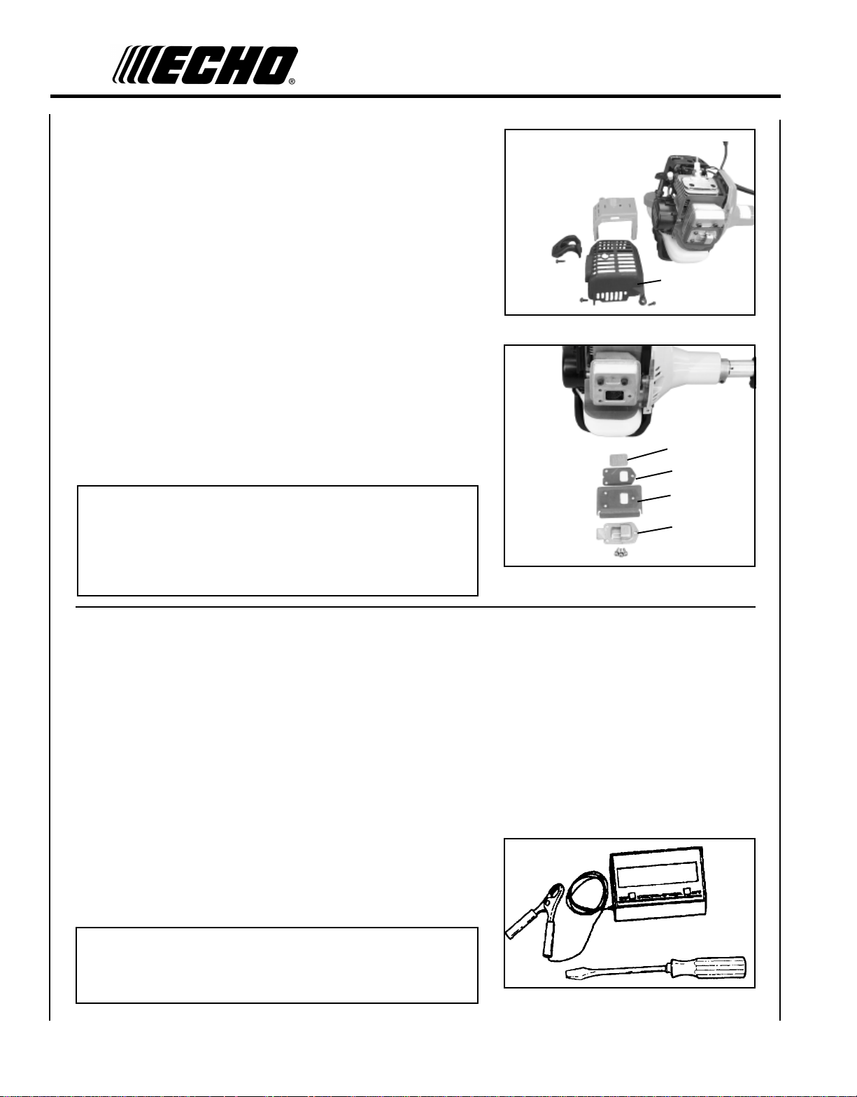
3. POWER HEAD - Includes the Engine, Clutch, Fuel System, Ignition System and Recoil Starter.
4. GRIP - Rear (right hand) handle.
5. STOP SWITCH - "SLIDE SWITCH" mounted on top of the Throttle Trigger Housing. Move switch FORWARD to
RUN, BACK to STOP.
6. FRONT HANDLE - The Front (loop) handle is loosely assembled to the Drive Shaft assembly and must be posi-
tioned for proper cutting attitude and operator comfort.
7. DRIVE SHAFT ASSEMBLY - Includes the Rear (right hand) Handle assembly, Gear Housing assembly, Front (loop,
left hand) Handle assembly, steel drive shaft and Safety Decal.
8. NYLON CUTTER HEAD - Contains replaceable nylon trimming line that advances when the trimmer head is tapped
against the ground while the head is turning at normal operating speed.
9. CUT-OFF KNIFE - Automatically trims line to the correct length: 5" after head is tapped on the ground. If trimmer is
operated without a cut-off knife, the line will become too long, the engine will overheat, and engine damage may
occur.
10. PLASTIC DEBRIS SHIELD ASSEMBLY - Included in plastic bag (co-pack). MUST be installed on unit before use,
see Assembly Instructions. Shield assembly includes the Cut-Off Knife. Mounts on the Gear Housing Assembly just
above the cutting attachment. Helps protect the operator by deflecting debris produced during the trimming operation. This shield must be replaced with the steel shield for blade use.
11. THROTTLE TRIGGER - Spring loaded to return to idle when released. During acceleration, press trigger gradually
for best operating technique.
12. SPARK PLUG - Provides spark to ignite fuel mixture.
13. ARM REST - Provides arm rest during operation and protects arm from the hot engine.
14. SPARK ARRESTOR - CATALYTIC MUFFLER / MUFFLER -The muffler or catalytic muffler controls exhaust noise
and emission. The spark arrestor screen prevents hot, glowing particles of carbon from leaving the muffler. Keep
exhaust area clear of flammable debris.
15. FUEL TANK - Contains fuel and fuel filter.
16. RECOIL STARTER HANDLE - Pull handle slowly until starter engages, then quickly and firmly. When engine
starts, return handle slowly. DO NOT let handle snap back or damage to unit will occur.
17. FUEL TANK CAP - Covers and seals fuel tank opening.
18. PRIMER BULB - Pumping primer bulb before starting engine draws fresh fuel from the fuel tank priming the carbure-
tor for starting. Pump primer bulb until fuel is visible and flows freely in the clear fuel tank return line. Pump bulb an
additional 4 or 5 times.
19. AIR CLEANER - Contains replaceable filter element.
20. CHOKE - The choke control is located on the top of the air filter case. Move choke lever to "Cold Start" to close
choke for cold start. Move choke lever to "Run" position to open choke.
21. SAFETY VIDEO - (Not included with unit) P/N 99922202540 English version only is available at a cost of $5.00 from
ECHO, INC. or any authorized ECHO dealer. The video overviews safety precautions and proper operating techniques and is supplemental to the Safety Manual. Read and understand the Safety Manual for complete information
on safe operation.
9
Page 10

10
ASSEMBLY
SPECIFICA TIONS
LEDOM062-MRSS062-MRS
daehrettuco/whtgneL
htdiW
thgieH
daeHrettuC/w)yrd(thgieW).bl9.11(gk93.5).bl5.11(gk2.5
epyTenignE enigneenilosagrednilycelgnis,ekorts-owt,deloocriA
eroB
ekortS
tnemecalpsiD
tsuahxE relffuMrotserrAkrapS
roterubraC pmupegrup/wJYWledommgarhpaidorblaW
metsySnoitingI egrahcsidroticapac,otengamleehwylF
gulPkrapS
leuF )liOekorts-owTdnaenilosaG(dexiM
oitaRliO/leuF lioenignedeloocriaekorts-owt,ecnamrofrePhgiHOHCE1:05
enilosaG
liO lioenignedeloocriaekorts-owt,ecnamrofrePhgiHOHCE1:05
).ni7.07(mm5971
).ni48.9(mm052
).ni48.9(mm052
).ni43.1(mm0.43
).ni01.1(mm0.82
).ni.uc55.1(cc4.52
).ni620.0(mm56.0paG(Y7-MPBKGN
.EBTM%51rolohoclalyhte%01
nahterom,lohoclalyhtemgniniatnocleufesuTONOD.dedaelnuenatcO98
yticapaCknaTleuF
metsySretratS retratSdniweRcitamotuA
hctulC epyTlagufirtneC
metsySdetalosInoitarbiV
doRgnitarepO
tfahSevirD tfahselbixelf).ni4/1(mm53.6tfahsleetsenilpsmm0.7
oitaResaCraeG noitcudeR4.1:1
noitceriDgnitatoR potmorfdeweiv;esiwkcolCretnuoC
daeHrettuC :lanoitpO).tf04(m31yticapaceniL™erifssorC590.htiw)enil-2(daehenilnolyN
*eldnaH spirgrebbur/weldnaHraeRthgiRdnapooL-tnorF
ssenraHredluohS lanoitpO
deepSeldI MPR0023-0082
daeHeniLnolyNhtiw
edalBhtiw
).T.O.W(deepSelttorhTnepOediW
).T.O.W(deepSelttorhTnepOediW
* Install and use U-Handle when operating any model with blade.
).zo.lfSU6.91(.til85.0
eldnahtnorfnopirgrebbuR.)ytudyvaeh(tnuomenignenonoihsucrebbuR
ebuTmunimulamm0.52
).ni8(wasralucriC;).ni8(edalbhtoot-22;).ni8(edalbrettuc8,tiKeldnaH-U
naelKknirpS,daeHredaoLdipaR,SDAEHLASREVINU,TUC-IRT,TUC-IXAM
MPR0069-0088
MPR00021-0059
Page 11
GRASS TRIMMER/BRUSH CUTTER
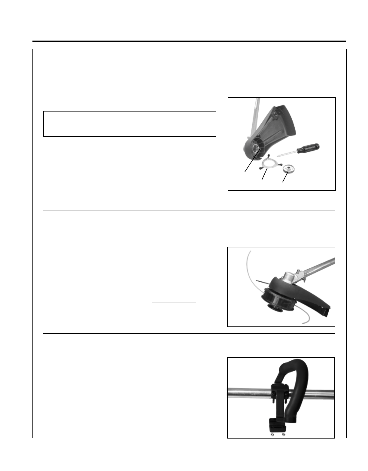
PLASTIC SHIELD INSTALLATION
(for Nylon Line Operation)
Tools Required: Screwdriver.
Parts Required: Plastic Shield, Shield Plate, three (3) 5mm x 15mm
screws.
NOTE
The plastic shield is for use with the Nylon Line Head only.
Install Metal Shield when using plastic or metal blades.
1 . Remove plastic threaded shaft sleeve and adapter plate (C) from
PTO shaft (A).
2. Place the shield on the bottom of the bearing housing flange.
OPERATOR'S MANUAL
11
3 . Place shield plate (B) on shield, align holes. Install three (3) screws
from bottom through plate and shield into gear case.
4 . Assemble adapter plate (C) onto PTO shaft.
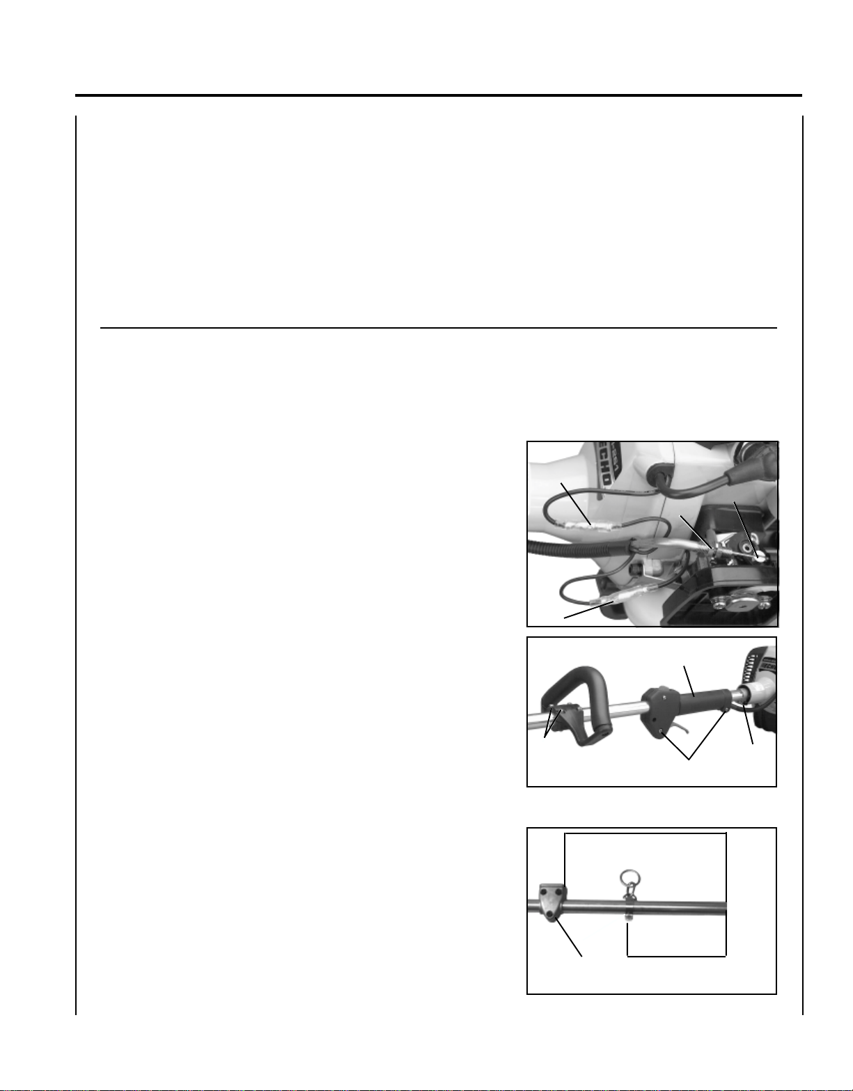
NYLON LINE HEAD INSTALLATION
Tools Required: Head Locking Tool.
Parts Required: Nylon Line Head.
1 . Be sure adapter plate (C) remains on PTO shaft.
2 . Align locking hole in upper plate with notch in edge of gear
housing and insert head locking tool (D).
3 . Thread line head onto shaft by turning it counter-clockwise until
head is tight against adapter plate (C).
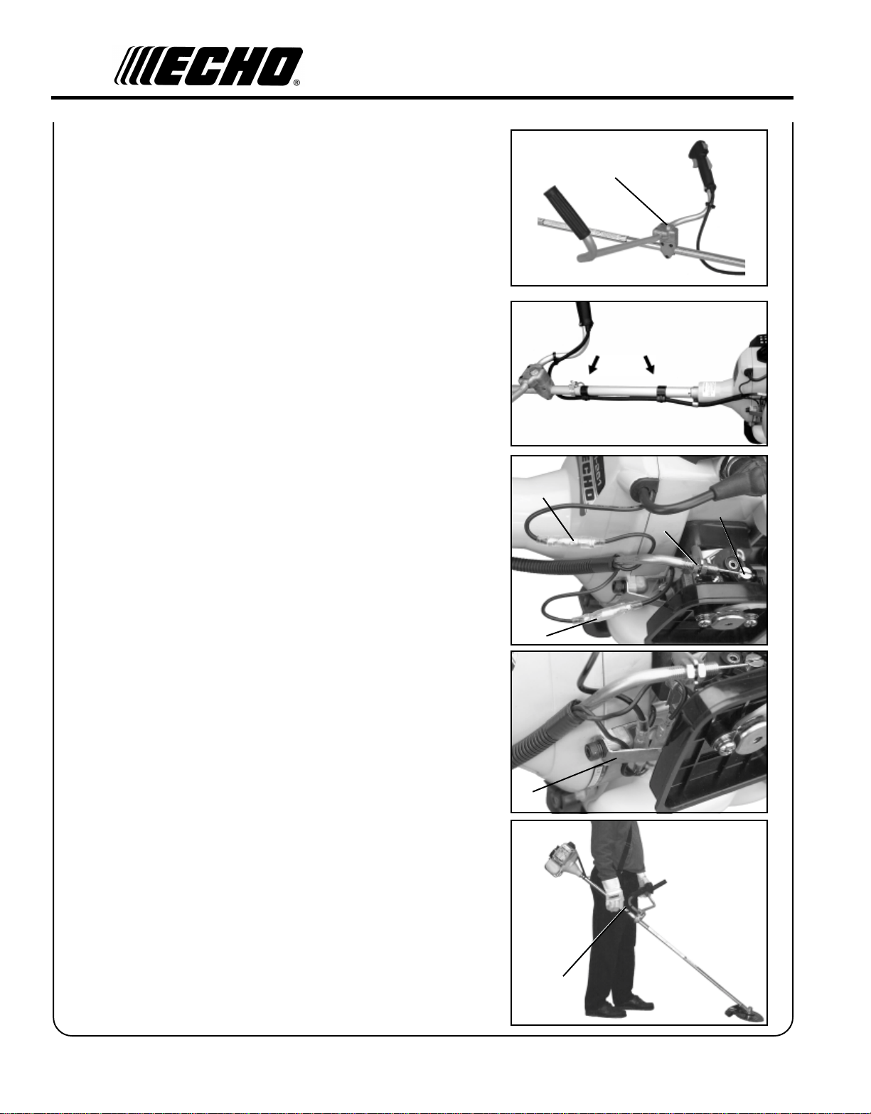
FRONT HANDLE INSTALLATION
A
B
D
C
Tools Required: Screwdriver.
Parts Required: Front Handle Assembly
1 . Position front handle for comfortable operation and secure screws.
Page 12

12
OPERATION WITH BLADES
Preparing the Trimmer/Brush Cutter for Blade Use
W ARNING DANGER
Blade use DEMANDS specific Brush Cutter configuration. Operation without specified shield and harness can result
in serious personal injury.
Plastic and Nylon Blades Require "Blade Conversion Kit,"
P/N 99944200415
(TRI-CUT [A] and shoulder harness [B]).
A
B
or U-Handle/Blade Conversion Kit P/N 99944200561
(metal blade [C] and shoulder harness [B]).
C
B
Choosing the Correct Blade
W ARNING DANGER
The type of Blade used MUST be matched to the type and size of material cut. An improper or dull blade can cause
serious personal injury. Blades MUST be sharp. Dull blades increase the chance of kick out and injury to yourself
and bystanders.
Plastic/Nylon Blades may be used where ever the nylon line head
is used. DO NOT use this blade for heavy weeds or brush!
Page 13

GRASS TRIMMER/BRUSH CUTTER
8 Tooth Weed/Grass Blade (P/N 69600120331) is designed for grass,
garden debris, and thick weeds. DO NOT use this blade for brush or
heavy woody growth, 19 mm (3/4 in.) diameter or larger.
Brush/Clearing Blade (P/N 69500120330) is designed for cutting brush
and woody growth up to 76 mm (3 in.) diameter.
Use Shoulder/Waist Harness (P/N 30100052131) Use of the Shoulder/
Waist Harness reduces operator fatigue and the possibility of blade
contact with the operator's hands and feet by restricting trimmer
movement.
OPERATOR'S MANUAL
13
HARNESS CLAMP INSTALLATION
(Plastic or Nylon Blade Use)
Tools Required: Screwdriver, 8mm x 10mm Open-End Wrench.
1. Remove shield and gear housing as an assembly.
a. Loosen two (2) screws (A) that clamp the gear housing to the
drive shaft housing.
b. Remove locating screw (B) found at the top of the gear
housing. Pull shield and gear housing assembly from the drive
shaft assembly.
IMPORTANT
Prevent drive shaft from sliding from drive shaft housing. If shaft
does slide free, clean dirt from shaft and re-assemble.
B
A
A
Page 14

14
2 . Remove front handle.
a. Remove four (4) screws and nuts and handle support from
handle.
b. Remove handle.
3 . Install clamp and front handle.
4 . Install gear housing with metal shield and blade. (See Metal Shield
and Blade Installation Instructions below.)
5 . Balance unit.
a. Put on harness and attach unit to harness.
b. Slide harness clamp (C) up or down until unit balances with
cutting attachment approximately 2 - 3 in. from the ground.
c. Tighten harness clamp screw.
MET AL SHIELD INSTALLATION
Tools Required: 8mm x 10mm Open End Wrench, Screwdriver.
Parts Required: Metal Shield, Bracket, 3 - 5mm x 15mm screws
w/captivated flat and lockwasher (metal shield to gear
housing), 2 - 5mm x 8mm screws, 4 - 5mm nuts,
4 - 5mm lockwashers (bracket to shield and bracket to
gear housing).
1 . If necessary, remove nylon line head and plastic shield.
2 . Loosely attach bracket (A) to shield (B) and attach to bottom of
gear housing (C) with screws and nuts provided. Tighten all
attaching hardware.
Install Blade
Tools Required: Locking Tool, T-wrench.
C
NYLON HEAD UPPER PLATE
D
SRM-260/260S
BLADE UPPER PLATE
Parts Required: 1 - 20mm Upper Fixing Plate, Grass Blade
(69600120330), Brush Blade (69500120330) or Tri-Cut
Blade w/Glide Cup (99944200030), 1 - Lower Fixing
Plate, 1 - 10mm L.H. Nut, 1 - 2x22mm Split Pin.
Page 15
GRASS TRIMMER/BRUSH CUTTER
3 . Install upper plate (D) on splined shaft. Blade installation requires
use of Upper Plate (D) with 20mm pilot. Upper plate with 37mm pilot
of the SRM-260/260S should be retained for use with nylon line
head.
4 . Place Blade (E) over upper plate pilot, install the Lower Plate (F)
and 10mm LH nut (G). Tri-Cut Blade (H) is installed with Glide
Cup (J).
5 . Insert Locking Tool (K) through hole in upper plate and notch in
gear housing to prevent splined shaft from turning. Tighten nut
and secure with Split Pin (L).
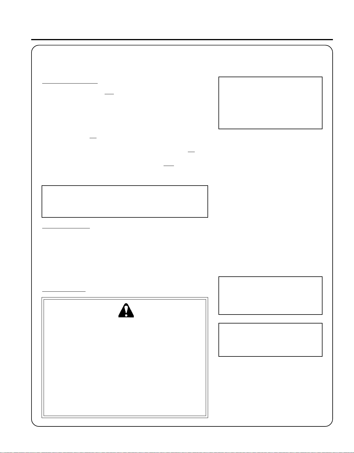
U-HANDLE INSTALLATION
Tools Required: 8mm x 10mm Open End Wrench, Screwdriver, 3mm
and 4mm Hex Wrench, Pliers
Parts Required: U-Handle/Blade Conversion Kit P/N 99944200451.
OPERATOR'S MANUAL
15
1 . Close choke and remove air filter cover.
2 . Disconnect ignition stop leads (A) and (B).
3 . Remove inner throttle linkage from carburetor swivel (C).
4 . Loosen nut (D) and remove throttle linkage from bracket.
5 . Loosen bolt (E) and pull drive shaft assembly from clutch case.
6 . Loosen two (2) rear handle screws (F) and pull rear handle (G) from
the drive shaft assembly.
7 . Loosen four (4) screws (H) and remove front handle.
8 . Position lower U-Handle bracket (J) 400mm (15-3/4 in.) from
engine end of drive shaft. Secure with three (3) 5mm x 30mm
bolts.
A
C
D
B
G
H
F
400 mm (15-3/4 in.)
E
9 . Position harness hook 220mm (8-5/8 in.) from engine end of drive
shaft assembly. DO NOT tighten at this time.
ENGINE
END
J
220 mm
(8-5/8 in.)
Page 16
16
10. Install upper U-Handle and bracket on lower bracket and secure
with one (1) 8mm x 55mm bolt (K) and large circular washer.
11. Install power head and align gear box, power head and U-Handles.
Tighten all screws.
12. Route throttle linkage and ignition lead assembly behind U-Handle
bracket, and clip to drive shaft as shown.
13. Place throttle linkage in slot in bracket. One nut on each side of
bracket. Finger tighten both nuts (D).
14 . Attach inner cable to swivel (C). Check throttle for freedom of
movement and that wide open throttle / low idle extremes are
adjusted properly. If adjustment cannot be achieved with adjusting
nuts, consult with your Echo Dealer for correct adjustment
procedure.
K
A
C
D
15. Connect ignition leads (A) and (B).
16. Secure ignition leads against engine housing with clip (L).
17 . Install air filter and cover.
18 . Balance unit.
a. Put on harness and attach unit to harness.
b. Slide harness clamp (M) up or down until unit balances with
cutting attachment approximately 2 - 3" from ground.
c. Tighten harness clamp screw.
B
L
M
Page 17
PRE - OPERATION
FUEL
GRASS TRIMMER/BRUSH CUTTER
OPERATOR'S MANUAL
17
Fuel Requirements
Gasoline - Use 89 Octane [ ] (mid grade or higher) gasoline known
to be good quality. Gasoline may contain up to 15% MTBE (methyl
tertiary-butyl ether). Gasohol containing methyl (wood) alcohol is NOT
approved.
Two Stroke Oil - A two-stroke engine oil meeting ISO-L-EGD (ISO/CD
13738) and J.A.S.O. FC Standards, must be used. Echo brand Premium
50:1 oil meets these standards. Engine problems due to inadequate
lubrication caused by failure to use an ISO-L-EGD and J.A.S.O. FC
certified oil, such as Echo Premium 50:1 Two-stroke Oil, will void the
two-stroke engine warranty. (Emission related parts only are covered
for two years, regardless of two-stroke oil used, per the statement listed
in the EPA Emission Defect Warranty Explanation.)
IMPORTANT
Echo Premium 2-Stroke Oil may be mixed at 50:1 ratio for application
in all Echo engines sold in the past regardless of ratio specified in
those manuals.
Mixing Instructions
1 . Fill an approved fuel container with half of the required amount of
gasoline.
2 . Add 2-stroke oil to gasoline.
3 . Close container and shake to mix oil with gasoline.
4 . Add remaining gasoline and remix.
5 . Install fuel container cap and wipe any spilled fuel from container
and surrounding area.
R + M
2
Handling Fuel
W ARNING DANGER
Fuel is VERY flammable. Use extreme care when mixing, storing or
handling, otherwise serious personal injury may result.
• Use an approved fuel container.
• DO NOT smoke near fuel.
• DO NOT allow flames or sparks near fuel.
• Fuel tanks/cans may be under pressure. Always loosen fuel
capsslowly allowing pressure to equalize.
• NEVER refuel a unit when the engine is HOT!
• NEVER refuel a unit with the engine running.
• DO NOT fill fuel tanks indoors. ALWAYS fill fuel tanks outdoors
over bare ground.
• Securely tighten fuel cap after refueling.
• Inspect for fuel leakage. If fuel leakage is found, do not start or
operate unit until leakage is repaired.
IMPORTANT
Spilled fuel is a leading cause of
hydrocarbon emissions. Some states
may require the use of automatic fuel
shut-off containers to reduce fuel
spillage. Contact your ECHO dealer for
ordering information.
After Refueling
• Wipe any spilled fuel from the unit.
• Move at least 3 m (10 ft.) from refueling
location before starting.
After Use
• DO NOT store a unit with fuel in its tank.
Leaks can occur. Return unused fuel to an
approved fuel storage container.
Storage
Fuel storage laws vary by locality. Contact
your local government for the laws affecting
your area. As a precaution, store fuel in an
approved, air tight container. Store in a well
ventilated, unoccupied building, away from
sparks and flames. Do not store fuel longer
than 30 days.
IMPORTANT
Stored fuel ages. Do not mix more fuel
than you expect to use in thirty (30)
days, ninety (90) days when a fuel
stabilizer is added.
IMPORTANT
Stored two-stroke fuel may separate.
ALWAYS shake fuel container
thoroughly before each use.
Page 18
18
OPERATION
STARTING
COLD ENGINE
W ARNING DANGER
The cutting attachment should not rotate at idle. If attachment
rotates, readjust carburetor according to "Carburetor Adjustment"
instructions in this manual or see your ECHO Dealer, otherwise
serious personal injury may result.
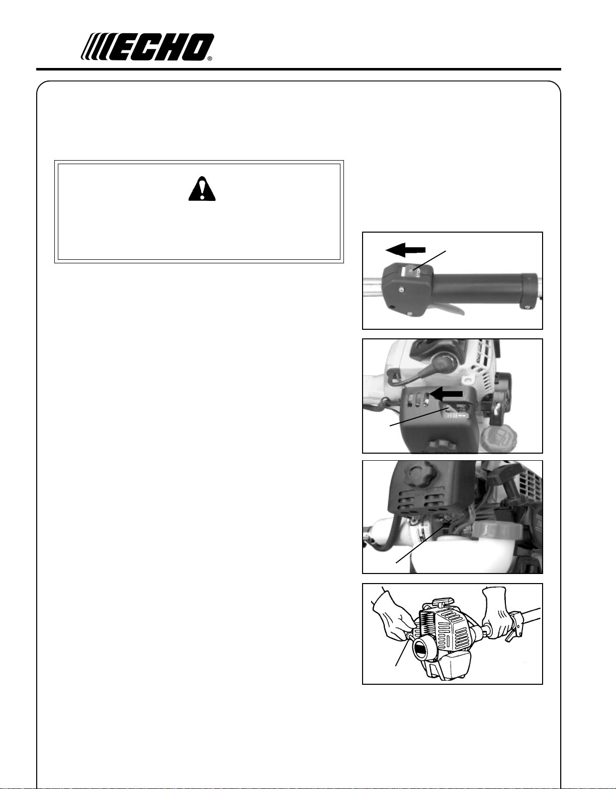
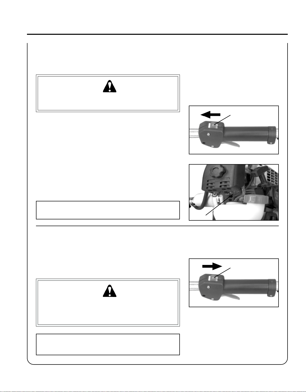
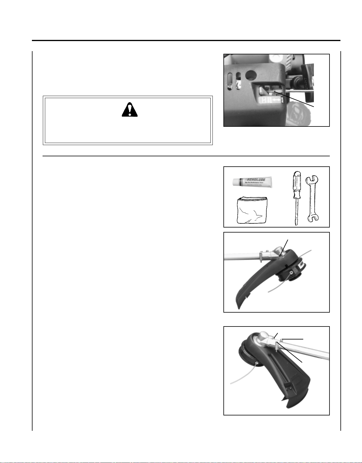
1. Stop Switch
Move stop switch button (A) forward away from the STOP
position.
2. Close Choke
Move choke lever (B) to Cold Start Position.
A
B
3. Primer
Pump primer bulb (C) until fuel is visible and flows freely in the
clear fuel tank return line. Pump bulb an additional 4 or 5 times.
4. Start
Lay the trimmer on a flat clear area and pull the recoil starter handle
(D) until engine fires (5 or 6 pulls).
5. Open Choke
Move the choke lever to the OPEN - RUN position. Restart engine
if necessary and allow to warm up running at idle for several
minutes.
C
D
Page 19
GRASS TRIMMER/BRUSH CUTTER
STARTING WARM ENGINE
The starting procedure is the same as Cold Start except DO NOT close
the choke.
W ARNING DANGER
When engine starts, the cutting attachment may rotate even with
the throttle trigger in idle (released) position.
1. Stop Switch
Move stop switch button (A) forward away from the STOP
position.
2. Primer
Pump primer bulb (C) until fuel is visible in the "Clear" fuel return
line.
OPERATOR'S MANUAL
A
19
3. Start
Lay the trimmer on a flat clear area and pull the recoil starter handle
(D) until the engine fires.
NOTE
If engine does not start after 5 pulls, use Cold Start Procedure.
STOPPING ENGINE
1. Release Throttle.
Allow engine to idle for a minute.
2. Stop Switch
Move stop switch button (A) backward to STOP position.
W ARNING DANGER
If engine does not stop when stop switch is moved to STOP
position, close choke - COLD START position - to stall engine.
Have your ECHO dealer repair stop switch before using trimmer
again.
C
A
NOTE
Refer to Grass Trimmer/Brush Cutter Safety Manual for proper and
safe trimming techniques.
Page 20

20
MAINTENANCE
Your ECHO unit is designed to provide many hours of trouble-free service. Regular scheduled maintenance will help your
unit achieve that goal. If you are unsure or are not equipped with the necessary tools, you may want to take your unit to
an ECHO Service Dealer for maintenance. To help you decide whether you want to DO-IT-YOURSELF or have the ECHO
Dealer do it, each maintenance task has been graded. If a task is not listed, see your ECHO Dealer for repairs.
SKILL LEVELS
Level 1 = Easy to do. Most required tools come with unit.
Level 2 = Moderate difficulty. Some specialized tools may be required.
Level 3 = Experience required. Specialized tools are required. ECHO recommends
that the unit be returned to your ECHO dealer for service.
ECHO offers REPOWER
TM
Maintenance Kits and Parts to make your maintenance job easier. Below each task heading
are listed the various part numbers required for that task. See your ECHO dealer for these parts.
MAINTENANCE INTERVALS
/TNENOPMOC
METSYS
ECNANETNIAM
ERUDECORP
D'QER
LLIKS
LEVEL
troPtsuahxErednilyCnobraceD/naelC/tcepsnI 3 C/I
etniaMflesruoY-tI-oD
retliFriAecalpeR/naelC/tcepsnI 1 C/I*R
ekohCnaelC/tcepsnI 2 C/I
retliFleuFecalpeR/tcepsnI 1 I*
skael,metsySleuFecalpeR/tcepsnI 1 *III
metsySgnilooCnaelC/tcepsnI 2 C/I
ROYLIAD
EROFEB
ESU
YREVE
LEUFER
serudecorPecnanetniaMrelaeDohcEdednemmoceR
serudecorPecnan
3
SHTNOM
09RO
SRUOH
6
SHTNOM
072RO
SRUOH
YLRAEY
006
SRUOH
R/I
rotserrAkrapSrelffuMecalpeR/tcepsnI 2 *
xelF(tfahSevirD
esaerG 2 )1(I
R/I
)sledoMelbaC
gnisuoHraeGesaerG 2 )2(I
epoRretratSlioceRnaelC/tcepsnI 1 *C/I
gulPk
rapSnaelC/tcepsnI 2 C/I*R
stloB/stuN/swercSecalpeR/nethgiT/tcepsnI 1 *R/I
SEDOCRETTELERUDECORPECNANETNIAM NAELC=C,ECALPER=R,TCEPSNI=I:
cA.mumixameranwohsslavretniemiT
:SETONERUDECORPECNANETNIAM
.esufosruoh52yreve
.esufosruoh05yreve
* ..noitcepsnignirudraewroegamadfognidnifehtnodesaberaecalperotsnoitadnemmocerllA
)1( OHCEylppA
)2( OHCEylppA
-ETONTNATROPMI deriuqerfoycneuqerfehtenimretedlliwecneirepxeruoydnaesulaut
.ecnanetniam
MT
EBUL
®
MT
EBUL
®
Page 21
GRASS TRIMMER/BRUSH CUTTER
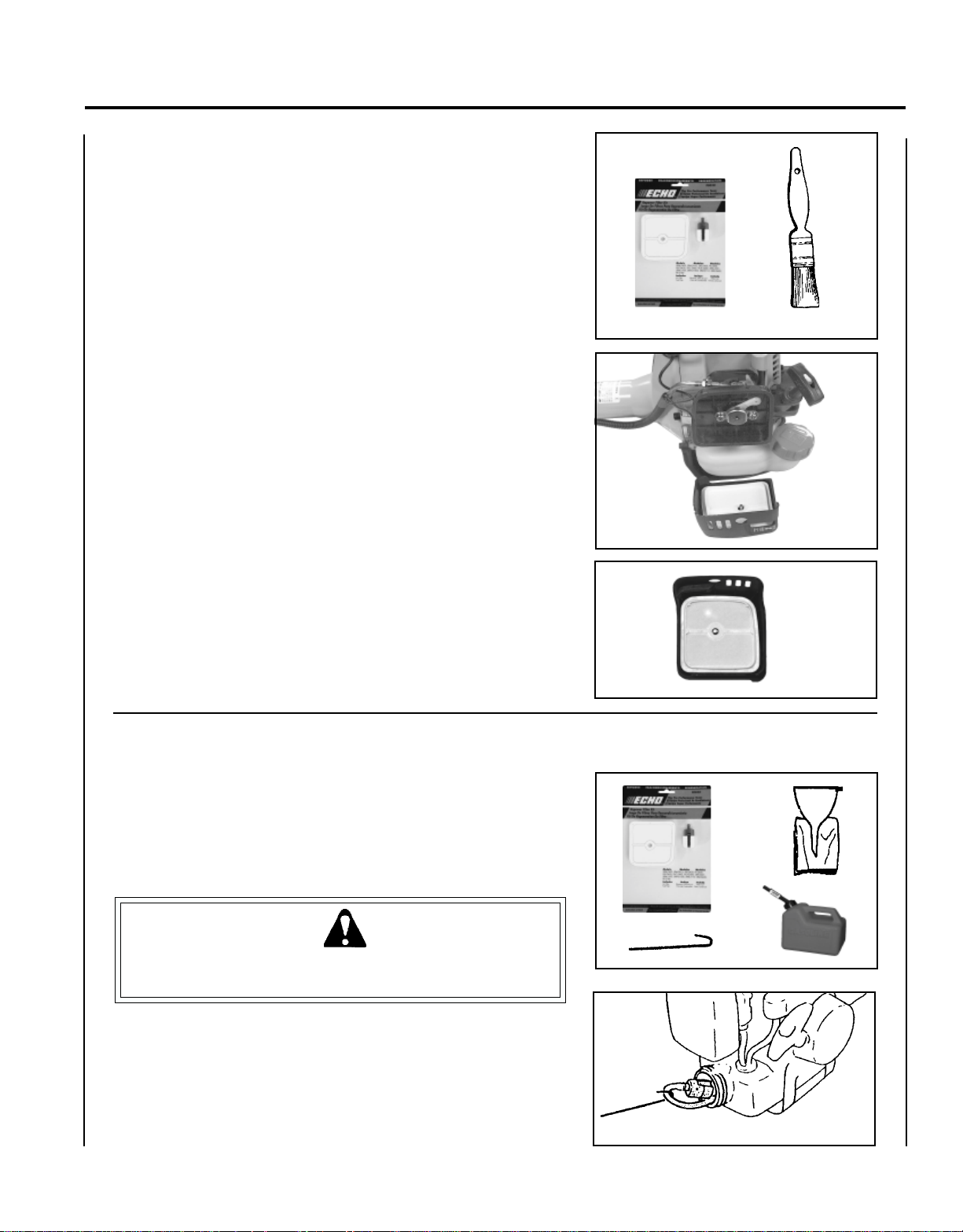
AIR FILTER
Level 1.
Tools required: Cleaning brush, 25 or 50 mm (1 or 2 in.) medium bristle
paint brush.
Parts required: 90030 REPOWERTM AIR & FUEL FILTER KIT.
1 . Close choke (Cold Start Position). This prevents dirt from
entering the carburetor throat when the air filter is removed.
Brush accumulated dirt from the air cleaner area.
2 . Remove the air cleaner cover. Clean and inspect the element for
damage. If element is fuel soaked and very dirty, replace.
OPERATOR'S MANUAL
21
3 . If element can be cleaned and reused, be certain it:
-still fits the cavity in the air cleaner cover.
-is installed with the original side out.
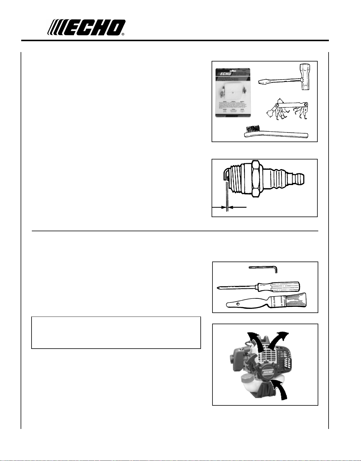
FUEL FILTER
Level 1.
Tools required: Fuel line hook, 200 - 250 mm (8 - 10 in.) length of wire
with one end bent into a hook. Clean rag, funnel, and
an approved fuel container.
Parts required: 90030 REPOWERTM AIR & FUEL FILTER KIT.
W ARNING DANGER
Fuel is VERY flammable. Use extreme care when mixing, storing or
handling.
1 . Use a clean rag to remove loose dirt from around fuel cap and
empty fuel tank.
2 . Use the “fuel line hook” to pull the fuel line and filter from the
tank.
3 . Remove the filter from the line and install the new filter.
Page 22
22
SPARK PLUG
Level 2.
Tools Required: T-Wrench (combination socket wrench and screw
driver supplied with unit), Feeler gauge, preferably a
wire gauge, Soft Metal Brush.
Parts Required: REPOWERTM TUNE-UP KIT 90065
1 . Remove spark plug and check for fouling, worn and rounded
center electrode.
2 . Clean the plug or replace with a new one. DO NOT sand blast to
clean. Remaining sand will damage engine.
3. Adjust spark plug gap by bending outer electrode.
4 . Tighten spark plug to 145-155 kg/cm (125-135 in. lb.).
COOLING SYSTEMS CLEANING
Level 2.
Tools required: Cross Head Screwdriver, 4 mm Hex Wrench, Cleaning
Brush, 25 - 50 mm (1 - 2 in.) medium bristle paint
brush.
Parts Required: None if you are careful.
IMPORTANT
To maintain proper engine operating temperatures, cooling air
must pass freely through the cylinder fin area. This flow of air
carries combustion heat away from the engine.
Overheating and engine seizure can occur when:
• Air intakes are blocked, preventing cooling air from reaching the
cylinder.
• Dust and grass build up on the outside of the cylinder. This build up
insulates the engine and prevents the heat from leaving.
0.65 mm
(0.026 in.)
Removal of cooling passage blockages or cleaning of cooling fins is
considered “Normal Maintenance.” Any failure attributed to lack of
maintenance is not warranted.
Page 23
1 . Remove spark plug lead.
GRASS TRIMMER/BRUSH CUTTER
OPERATOR'S MANUAL
23
2 . Remove two (2) muffler cover screws and muffler cover (A).
3 . Remove screw and arm rest (B).
4 . Remove engine cover (C).
IMPORTANT
DO NOT use a metal scraper to remove dirt from the cylinder fins.
5 . Use brush to remove dirt from the cylinder fins.
6 . Remove grass and leaves from the grid between the recoil starter
and fuel tank.
C
B
A
EXHAUST SYSTEM
Spark Arrestor Screen
Level 2.
Tools Required: Cross Head Screwdriver, Soft Metal Brush, 4 mm Hex
Wrench
Parts Required: Spark Arrestor Screen P/N 14586251030.
Page 24
24
1 . Remove engine cover (A). See “Cleaning Cooling System” pages
22 & 23 for step by step instructions.
2 . Place piston at Top Dead Center (TDC) to prevent carbon/dirt from
entering cylinder.
3 . Remove spark arrestor screen cover (B), screen holder (C), gasket
(D), and screen (E), from muffler body.
4 . Clean carbon deposits from screen and muffler components.
5 . Replace screen if it is cracked, plugged, or has holes burned
through.
6. Assemble components in reverse order.
Cylinder Exhaust Port
Level 3.
IMPORTANT
The cylinder exhaust port must be inspected and cleaned of excess
carbon every 3 months or 90 hours of operation in order to maintain
this engine within the emissions durability period. ECHO strongly
recommends that you return your unit to your ECHO dealer for this
important maintenance service.
CARBURETOR ADJUSTMENT
Engine Break-In
New engines must be operated a minimum of two tanks of fuel before
carburetor adjustments can be made. During the break-in period your
engine performance will increase and exhaust emissions will stabilize.
Idle speed can be adjusted as required.
A
E
D
C
B
High Altitude Adjustment
High altitude adjustment is not required for proper operation of this
engine.
Level 2.
Tools required: Screwdriver, Tachometer (ECHO P/N 99051130017).
Parts required: None.
NOTE
Every unit is run at the factory and the carburetor is set in compliance with EPA Emission Regulations. This carburetor does not
have acceleration and high speed adjustment needles.
Page 25
GRASS TRIMMER/BRUSH CUTTER
1 . Check idle speed and reset if necessary. If a tachometer is avail-
able, idle speed screw (A) should be set to the specifications found
on page 10 "Specifications" of this manual. Turn idle screw (A)
clockwise to increase idle speed; counter clockwise to decrease idle
speed.
W ARNING DANGER
When carburetor adjustment is completed, the cutting attachment
should not turn at idle, otherwise serious personal injury may
result.
LUBRICA TION
Level 1.
OPERATOR'S MANUAL
25
A
Tools Required: 8 mm Open End Wrench, Screwdriver, Clean Rag.
Parts Required: ECHO® LUBETM 8 oz. (P/N 91014) or Lithium Base
Grease.
Gear Housing
1 . Clean all loose debris from gear box.
2 . Remove plug (A) and check level of grease.
3 . Add grease if necessary. DO NOT over-fill.
Drive Shaft
1 . Loosen two (2) screws (B) and remove center locating screw (C).
Pull gear box and shield from drive shaft housing.
2 . Pull flexible cable from the drive shaft housing, wipe clean and
re-coat with a thin coating [15 ml (1/2 oz.)] of grease.
A
A
C
B
B
3 . Slide the flexible cable back in the drive housing. DO NOT get
dirt on the flex cable.
4. Install the gear housing and shield assembly.
Page 26

26
NYLON LINE REPLACEMENT
Level 1.
Tools Required: Head locking tool (if head is to be removed)
Parts Required: ECHO 0.095" Nylon Trimmer Line 12 m (40 feet) long.
1 . Hold drum (A) and turn spool (B) CW (clockwise) until it stops.
Pull spool from drum. DO NOT push in on spool when turning.
2 . Use one piece of new nylon line (C) 12 m (40 ft.) long and thread
through the molded loop (D) on the spool. Pull line tight and
adjust so one end is 15 cm (6 in.) longer than the other.
3 . Hold the spool, opening toward you. Place index finger between
the two strands and wind line, tightly and evenly, in direction of
arrow marked "CC".
4 . Stop when approximately 15-20 cm (6 - 8 in.) line (C) remains and
place ends of line in notches (E) in spool (B).
5. Feed ends of lines through housing eyelets (F), and place spool (B)
over drive (G). Align pegs (H) on drive with notches in spool and
push spool into drum.
6 . Pull on both lines until they come free from notches (E) in spool.
7 . Hold drum (A) firmly and turn spool (B) CCW (counterclockwise)
until it stops. DO NOT push in on spool when turning.
8 . Pull both lines out and trim to cut-off knife length.
Page 27

GRASS TRIMMER/BRUSH CUTTER
SHARPENING METAL BLADES
Three styles of metal blades are approved for use on the ECHO Brush
Cutter. The 8-tooth blade can be sharpened during normal maintenance.
The clearing blade and 80 tooth blade require professional service.
Before sharpening, CLOSELY inspect blade for cracks (look at the
bottom of each tooth and the center mounting hole closely), missing
teeth and bending. If ANY of these problems are discovered, replace
the blade.
When sharpening a blade, always remove the same amount of materials
from each tooth to maintain balance. A blade that is not balanced will
cause unsafe handling due to vibration and can result in blade failure.
8-tooth Blade
Tool required: Flat file (preferred). Electric grinder if special care is
used. Round (rat tail) file for gullet (radius).
OPERATOR'S MANUAL
27
1 . File each tooth at a 30 degree angle a specific number of times,
eg. 4 strokes per tooth. Work your way around the blade until
all teeth are sharp.
2 . DO NOT file the 'gullet' (radius) of the tooth with the flat file.
The radius must remain. A sharp corner will lead to a crack and
blade failure.
IMPORTANT
If an electric grinder is used, use care not to overheat teeth. DO
NOT allow tips/tooth to glow red or turn blue. DO NOT place blade
in cooling water. This will change the temper of the blade and could
result in blade failure.
3. After sharpening teeth, check each tooth radius for evidence of a
square (sharp) corner. Use the round (rat tail) file to renew the
radius.
Page 28

28
TROUBLESHOOTING
melborPkcehCsutatSesuaCydemeR
TRAHCGNITOOHSELBUORTMELBORPENIGNE
roterubractaleuF
enignE
-sknarc
/drahstrats
t'nseod
trats
enignE
,snur
roseidtub
tonseod
etarelecca
ylreporp
rednilyctaleuF
dnetakrapS
eriwgulpfo
gulptakrapSkrapsoN
retlifriAytridretlifriAraewlamroNecalperronaelC
retlifleuFytridretlifleuF
tnevleuFdeggulptnevleuF
gulPkrapSnrow/ytridgulPraewlamroNecalperrotsujdadnanaelC
roterubraC
taleufoN
roterubrac
rednilyctaleufoNroterubraCrelaedohcEruoyeeS
leufhtiwtewrelffuMhcirooterutxiMleuF
krapsoN
reporpmI
tnemtsujda
roterubraC
evitcefedgulP
leufni
leufni
noitarbiVtsujdA
deggolcreniartsleuF
deggolcenilleuF
ffohctiwspotS
melborplacirtcelE
hctiwskcolretnI
tcerrocnipagkrapS
nobrachtiwderevoC
leufhtiwdeluoF
seudiser/stnanimatnoC
seudiser/stnanimatnoC
ecalpeR
ecalperronaelC
ecalperronaelC
relaedohcEruoyeeS
ekohcnepO
retlifriaecalper/naelC
roterubractsujdA
relaedohcEruoyeeS
NOothctiwsnruT
relaedohcEruoyeeS
relaedohcEruoyeeS
).ni620.0(mm56.ottsujdA
ecalperronaelC
ecalperronaelC
gulpecalpeR
ecalperronaelC
metsySgnilooC
rotserrAkrapS
neercS
enignE
d
seo
n
to
c
knar
A/NA/NmelborpenignelanretnIrelaedohcEruoyeeS
evissecxE
sirbed/trid
,dekcarcneercS
ro,deggulp
detarofrep
raewlamroNecalpeR
ninoitarepodednetxE
snoitacolytsud/ytrid
naelC
W ARNING DANGER
Fuel vapors are extremely flammable and may cause fire and/or explosion. Never test for ignition spark near an open
spark plug opening, otherwise serious personal injury may result.
Page 29

STORAGE
Long Term Storage (over 30 days)
GRASS TRIMMER/BRUSH CUTTER
OPERATOR'S MANUAL
29
W ARNING
During operation the muffler or catalytic muffler and surrounding cover become hot. Always keep exhaust area clear
of flammable debris during transportation or when storing, otherwise serious property damage or personal injury may
result.
Do not store your unit for a prolonged period of time (30
days or longer) without performing protective storage
maintenance which includes the following:
1 . Store unit in a dry, dust free place, out of the reach of
children.
W ARNING DANGER
Do not store in enclosure where fuel fumes may
accumulate or reach an open flame or spark.
2. Place the stop switch in the "OFF" position.
3 . Remove accumulation of grease, oil, dirt, and debris
from exterior of unit.
4 . Perform all periodic lubrication and services that are
required.
DANGER
6. Drain the fuel tank completely and pull the recoil
starter handle several times to remove fuel from the
carburetor.
7 . Remove the spark plug and pour 7 cc (1/4 oz.) (1/2
tablespoon) of fresh, clean, two-stroke engine oil into
the cylinder through the spark plug hole.
A. Place a clean cloth over the spark plug hole.
B . Pull the recoil starter handle 2-3 times to
distribute the oil inside the engine.
C. Observe the piston location through the spark
plug hole. Pull the recoil starter handle slowly
until the piston reaches the top of its travel and
leave it there.
8. Install the spark plug (do not connect ignition cable).
5. Tighten all the screws and nuts.
Page 30

30
NOTES
Page 31

GRASS TRIMMER/BRUSH CUTTER
OPERATOR'S MANUAL
NOTES
31
Page 32
SERVICING INFORMATION
P ARTS
Genuine ECHO Parts and ECHO REPOWER™ Parts and Assemblies for
your ECHO products are available only from an Authorized ECHO
Dealer. When you do need to buy parts, always have the Model
Number and Serial Number of the unit with you. You can find these
numbers on the engine housing. For future reference, write them in the
space provided below.
Model No. _____________ SN. ____________
SERVICE
Service of this product during the warranty period must be performed
by an Authorized ECHO Service Dealer. For the name and address of
the Authorized ECHO Service Dealer nearest you, ask your retailer or
call: 1-800-432-ECHO (3246). Dealer information is also available on our
Web Site. When presenting your unit for Warranty service/repairs,
proof of purchase is required.
www.echo-usa.com
DEALER?
CALL
1-800-432-ECHO
OR
ECHO CONSUMER PRODUCT SUPPORT
If you require assistance or have questions concerning the application,
operation or maintenance of this product, you may call the ECHO
Consumer Product Support Department at 1-800-673-1558 from 8:30 am
to 4:30 pm (Central Standard Time) Monday through Friday. Before
calling, please know the model and serial number of your unit to help
your Consumer Product Support Representative.
CONSUMER PRODUCT
SUPPORT
1-800-673-1558
8:30 - 4:30 MON - FRI C.S.T.
WARRANTY REGISTRATION
You may register your Echo equipment using the warranty registration
card or register on-line at www.echo-usa.com. Registering provides a
direct link between you and ECHO if we find it necessary to contact
you.
ADDITIONAL OR REPLACEMENT MANUALS
Safety Manuals in English/Spanish or English/French are available, free of charge, from your ECHO dealer or at
www.echo-usa.com.
Operator's and Parts Manuals are available by:
• Downloading free from www.echo-usa.com
• Purchasing from your Echo Dealer.
• Sending a check or money order for $2.00 per Parts Catalog or $1.50 per Operator's Manual made payable to ECHO,
INCORPORATED. State on a sheet of paper the model number and serial number of the ECHO unit you have, part
number of the manual (if known), your name and address, and mail to address below.
Safety Videos are available from your Echo dealer. A $5.00 shipping charge is required for each video.
Available Parts Catalog Parts Lists
SRM-260/260S S/N 003001001 & UP PART NUMBER 99922203286
ECHO, INCORPORATED
400 OAKWOOD ROAD
LAKE ZURICH, IL 60047
www.echo-usa.com
Page 33

SUPPLEMENT TO OPERATOR'S
MANUAL
* Some Echo units may be factory pre-assembled. The nylon line head, plastic debris shield, and mounting hardware shown in the
contents list are pre-assembled to the unit. No assembly tools are needed. The front handle may need to be re-positioned for
comfortable operation.
GT CONTENT LIST
*_ - Rapid Loader
TM
2-line Head
*_ - Shield Assembly
*_ - Line Head Mount Hardware
*_ - 1, 3/8-24 Locknut
*_ - 1, Small Washer
*_ - 1, Large Washer
*_ - 12, 8 in. x .080 Pre-cut Nylon Line
*_ - 1, Locking Tools, P/N 89751801131
SRM CONTENT LIST
* ___ - 1, Nylon Trimmer Head
* ___ - 1, wrench 17x19, P/N 89541008030
* ___ - 1, locking tool, P/N 89751801131
* ___ --1, Plastic shield
* ___ --1, shield plate
* ___ --3, 5mm x 15mm screws (shield mtg.)
SUPLEMENTO DEL MANUAL DEL OPERADOR
* Algunas unidades pueden venir ya montadas de fábrica. La cabeza del hilo de nilón, proyector de plástico contra residuos y la
tornilleria de montaje, mostrados en la lista del contenido, vienen ya montados en la unidad. No se necesita ninguna herramienta de
montaje. Tal vez sea necesario volver a ubicar solamente la empuñadura delantera para facilitar la operación.
LISTA DE CONTENIDO DE GT
*_ - Cabeza Rapid Loader
*_ - Conjunto de protector
*_ - Tornilleria de montaje de la cabeza de línea
*_ - 1, tuerca de traba de 3/8-24
*_ - 1, arandela pequeña
*_ - 1, arandela grande
*_ - 12, hilo de nilón precortado de 8 pulg. x 0,080
*_ - 1, herramientas de traba, P/N 89751801131
TM
de 1 hilo
LISTA DE CONTENIDO DE SRM
* ___ - 1, cabeza recortadora de nilón
* ___ - 1, llave 17x19, N/P 89541008030
* ___ - 1, herramienta de traba, N/P 89751801131
* ___ —1, protector de plástico
* ___ —1, placa protectora
* ___ —3 ,tornillos de 5 mm x 15 mm (de montaje del protector)
SUPPLÉMENT AU MANUEL DE L’OPÉRATEUR
* Certains modèles sont assembles en usine. La tête de coupe à ligne nylon, le pare-débris en plastique et la boulonnerie de montage
illustrée dans la liste des pièces sont installés sur l’outil. Aucun outil d’assemblage n’est requis. Il peut toutefois être nécessaire
d’ajuster la poignée avant pour assurer le confort d’utilisation.
LISTE DU CONTENU - GT
*__ - Tête 2 lignes Rapid Loader
*__ - Pare-débris
*__ - Boulonnerie de montage de la tête à ligne
*__ - Écrou de blocage de 3/8-24
*__ - 1 petite rondelle
*__ - 1 grosse rondelle
*__ - 12 lignes nylon précoupées de 8 x 0,080 po
*__ - 1, outils de blocage réf. 89751801131
SUP22203624
TM
LISTE DU CONTENU - SRM
* ___ - 1 tête de coupe à ligne nylon
* ___ - (1) joints, réf. 89541008030
* ___ - 1 outil de blocage, réf. 89751801131
* ___ —1 pare-débris en plastique
* ___ —1 plaque de pare-débris
* ___ — 3 vis 5 mm x 15 mm (pare-débris)
99922203624
09/02
 Loading...