

Page 1

1
INTRODUCTION
We are constantly working on technical
improvement of our products. For this reason,
technical data, equipment and design are subject to
change without notice. All specifications,
illustrations and directions in this SERVICE DATA
are based on the latest products information
available at the time of publication.
For further information about the engine to service
these models, please refer to ECHO SERVICE
MANUAL Ord. No. 402-18.
ENGINE DRILL
EDR-2100 EDR-2100/1E
EDR-2400 EDR-2400/1E
Reference No. 19-21A-02
REVISED: 199807
SERVICE DATA
1
19-21A-02
CONTENTS
page
1 SERVICE INFORMATION ............................ 2
1-1 Specifications ............................................ 2
1-2 Technical data .......................................... 3
1-3 Torque limits ............................................. 4
1-4 Special repairing materials ....................... 4
1-5 Service limits ............................................. 5
1-6 Special tools ............................................. 6
2 SERVICE HINT ............................................. 7
2-1 Transmission construction ........................ 7
2-2 Clutch function .......................................... 8
ISSUED: 199609
EDR-2100 EDR-2400
Remarks:
Please use this revised edition (Reference No. 19-21A-02)
and discard all previous issues.
INDEX
Page 2
1 SERVICE INFORMATION
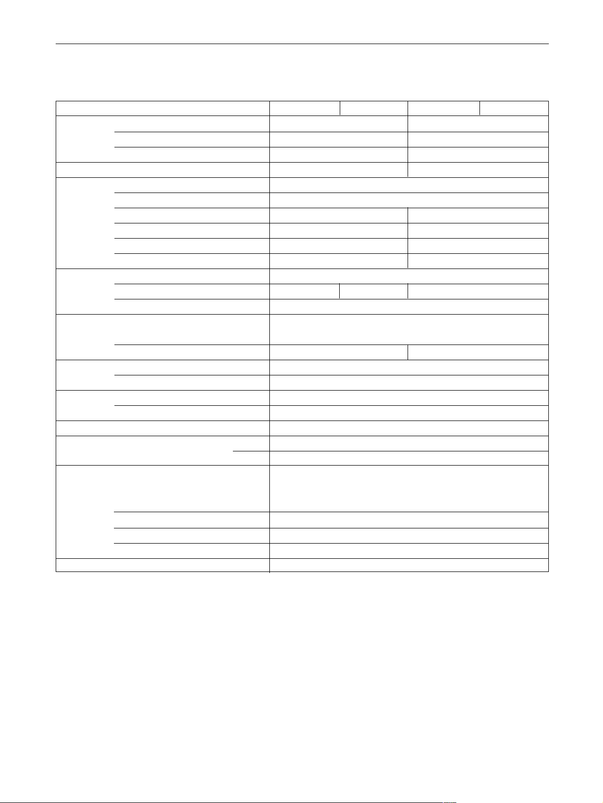
1-1 Specifications
Models EDR-2100 EDR-2100/1E EDR-2400 EDR-2400/1E
Dimensions Length mm(in) 430 (16.9) 430 (16.9)
Width mm(in) 320 (12.6) 320 (12.6)
Height mm(in) 255 (10.0) 255 (10.0)
Dry weight (without drill) kg(lb) 4.6 (10.1) 4.7 (10.3)
Engine Type KIORITZ, air-cooled, two-stroke, single cylinder
Rotation Counterclockwise as viewed from the output end
Displacement cm
3
(in3) 21.2 (1.294) 23.6 (1.440)
Bore mm(in) 32.2 (1.268) 34.0 (1.339)
Stroke mm(in) 26.0 (1.024) 26.0 (1.024)
Compression ratio 6.5 6.3
Carburetor Type
Walbro diaphragm, horizontal-draught, with primer (purge pump)
Model WYL-23 WYL-53 WYL-56
Venturi size-Throttle bore mm(in) 9.0 - 9.0 (0.354 - 0.354)
Ignition Type CDI (Capacitor discharge ignition) system
in a single integrated piece
Spark plug BPM7Y, RCJ-8Y BPM7Y, BPMR7A
Starter Type Automatic rewind
Rope diameter x length mm(in) 3.0 x 1000 (0.12 x 39.4)
Fuel Type Premixed two-stroke fuel (Refer to Operator's manual.)
Tank capacity cm
3
(U.S.fl.oz.) 420 (14.2)
Clutch Type Centrifugal, 2-shoe slide
Handle Type Front Bar with rubber grip
Rear Rubber grip with throttle trigger
Transmission
Reduction ratio 17.1 (Regular)
18.6 (Reverse)
Gear tooth Spur
Lubrication Grease
Chucking capacity(dia. max)
mm(in) 13.0 (0.51)
Drill Maximum diameter mm(in) 30.0 (1.18)
2
SERVICE INFORMATION
EDR-2100 EDR-2100/
1E
EDR-2400 EDR-2400/
1E
Page 3

1-2 Technical data
Models EDR-2100 EDR-2100/1E EDR-2400 EDR-2400/1E
Engine
Idling speed rpm 2500 - 3500
Engine speed at maximum power rpm 7000
Maximum speed rpm 9000
Clutch-in speed rpm 4000
Compression pressure kgf/cm
2
(psi) 9.5 (135) 8.5 (120)
Carburetor
Main jet #37 #38
Metering needle initial setting turns in 12* - - - - - Test pressure, minimum kgf/cm
2
(psi) 0.5 (7.0)
Metering lever height mm(in) 1.5 (0.06) lower than diaphragm seat
Ignition system
Spark plug gap mm(in) 0.6 - 0.7 (0.024 - 0.028)
Minimum secondary voltage
at 1000 rpm
kV 15
Secondary coil resistance kΩ 1.0 - 2.0
Pole shoe air gaps mm(in) 0.3 - 0.4 (0.012 - 0.016)
Ignition timing °BTDC ( 33 ) 28 28
* Screw in metering needle from initial threads engagement.
BTDC: Before top dead center.
3
EDR-2100 EDR-2100/
1E
EDR-2400 EDR-2400/
1E
SERVICE INFORMATION
Page 4

1-3 Torque limits
Descriptions Size kgf•cm in•lbf
Starter Pawl carrier M 8 160 - 200 140 - 175
system
Ignition Ignition coil (CDI module) M 4 30 - 50 26 - 45
system
Spark plug M14 150 - 170 130 - 150
Fuel Carburetor insulator M 5 * 25 - 40 22 - 35
system
Carburetor M 5 30 - 40 26 - 35
Throttle wire housing nut M 6 25 - 35 22 - 30
Fuel tank M 5 * 30 - 45 26 - 40
Clutch Clutch M 8 160 - 200 140 - 175
Clutch case M 4 15 - 28 13 - 24
Engine Crankcase M 5 170 - 110 60 - 95
Cylinder M 5 170 - 110 60 - 95
Cylinder cover (fan side) M 4 15 - 28 13 - 24
Cylinder cover M 4 10 - 20 19 - 17
(starter side)
Muffler M 5 60 - 90 52 - 78
Handle Rear handle (gear case) M 5 60 - 80 52 - 70
Rear handle (supporter) M 5 30 - 45 26 - 40
Rear handle supporter M 4 * 30 - 50 26 - 45
w/stand & starter case
Gear Shaft for small spur gear M 6 * 170 - 110 60 - 95
case PTO shaft M12 350 - 450 300 - 390
Chuck M12 350 - 450 300 - 390
Chuck center bolt M 6 * 150 - 180 130 - 155
Gear case M 5 60 - 80 52 - 70
Regular bolt, nut, and screw M 3 16 - 10 5 - 9
M 4 15 - 25 13 - 22
M 5 25 - 45 22 - 40
M 6 45 - 75 40 - 65
M 8 110 - 150 995 - 130
Material Location Remarks
Grease Rewind spring
Starter center shaft Lithium based grease
Gear case bearing collar
PTO shaft press-in
Gear case 15g in each gear case Total 45g
Thread locking sealant Carburetor insulator screws
Fuel tank screws
Rear handle supporter Loctite #222, ThreeBond #1342 or equivalent
w/stand & starter case bolts
Shaft for small spur gear bolt
Clutch case bearing press-in Loctite #675
1-4 Special repairing materials
* Apply thread locking sealant. (See below.)
4
SERVICE INFORMATION
EDR-2100 EDR-2100/
1E
EDR-2400 EDR-2400/
1E
Page 5

1-5 Service limits
Description EDR-2100 EDR-2400
A Cylinder bore When plating is worn and aluminum can be seen
B Piston outer diameter Min. mm(in) 32.10 (1.264) 33.90(1.335)
C Piston pin bore Max. mm(in) 8.030 (0.3161)
D Piston ring groove Max. mm(in) 1.6 (0.063)
E Piston ring side clearance Max. mm(in) 0.1 (0.004)
F Piston pin outer diameter Min. mm(in) 7.98 (0.3142)
G Piston ring width Min. mm(in) 1.45 (0.057)
H Piston ring end gap Max. mm(in) 0.5 (0.02)
K Crankshaft runout Max. mm(in) 0.05 (0.002)
L Clutch drum bore Max. mm(in) 51.5 (2.03)
5K193 5K228 5K229 5K230
5K231 5K016
5K042 5K194
0
1
2
3
4
5
6
7
8
9
1
0
1
1
1
2
0
5
1
0
5K171
5K232
ABCD
EFGH
KL
5
EDR-2100 EDR-2100/
1E
EDR-2400 EDR-2400/
1E
SERVICE INFORMATION
Page 6

1-6 Special tools
a
1
7
11
15
2
8
12
16
3 4: a=4mm
5: a=3mm
9
13
17
6
10
14
Key Part Number Description Used for:
1 Tachometer Measuring engine speed
2 363018-00310 Washer Installing crankcase oil seal of starter side
3 433019-12330 Flange nut Removing magneto rotor (flywheel)
4 895610-79920 L-hex wrench (4 mm) Removing and installing hex. socket bolts (M5)
5 895612-79920 L-hex wrench (3 mm) Removing and installing hex. socket bolts (M4)
6 897701-06030 Bearing wedge Removing ball bearings on crankshaft
7 897701-14732 Bearing tool Removing and installing crankcase ball bearings
8 897702-30131 Piston pin tool Removing and installing piston pin (Use 8 mm dia. adapter.)
9 897705-11520 Bearing tool Removing and installing con-rod small end needle bearing
10 897712-04630 2-pin wrench Removing and installing pawl carrier
11 897714-22830 Bearing and seal tool Installing ball bearing in gear case
12 897714-24330 Oil seal tool Installing crankcase oil seals
13 897726-09130 Bearing and seal tool Removing clutch drum and installing clutch drum ball bearing
14 897800-79931 Spark tester Checking ignition system
15 897803-30130 Pressure tester Checking carburetor and crankcase leakages
16 897835-16131 Pressure connector Checking crankcase and cylinder leakages
17 900100-08008 Bolt Removing magneto rotor (flywheel)
6
SERVICE INFORMATION
EDR-2100 EDR-2100/
1E
EDR-2400 EDR-2400/
1E
Page 7

7
EDR-2100 EDR-2100/
1E
EDR-2400 EDR-2400/
1E
SERVICE HINT
2 SERVICE HINT
2-1 Transmission construction
Clutch drum
Gear 1
Gear 6
Gear 5
Gear 2
Gear 3
Gear 4
Clutch nail
Chuck
PTO shaft
Gear 7
Clutch lever
Gear 6
Gear 3
Page 8

2-2 Clutch function
8
SERVICE HINT
EDR-2100 EDR-2100/
1E
EDR-2400 EDR-2400/
1E
Clutch drum
Gear 1
Gear 6
Gear 5
Gear 2
Gear 3
Gear 4
Clutch nail
Chuck
Gear 7
Clutch lever
PTO shaft
Gear 3
Gear 6
1. Gear 2 engages with Gear 1 on Clutch drum shaft.
Gear 3 engages with Gear 7 and Gear 7 engages
with Gear 6. Gear 4 engages with Gear 5.
2. When engine speed goes up and centrifugal clutch
engages, the clutch drum(Gear 1) drives Gear 2.
Gear 2, Gear 3 and Gear 4 are one solid part.
Gear 5 is driven by Gear 4 to turn clockwise.
Gear 7 is driven by Gear 3.
Gear 6 is driven by Gear 7 to turn counterclockwise.
3. In the neutral position, Gear 5 and Gear 6 rotate
freely on PTO shaft. When clutch nail is moved by
clutch lever to engage with Gear 5, PTO shaft turns
clockwise. When clutch nail is moved by clutch lever
to engage with Gear 6, PTO shaft turns counterclockwise.
Gear 6
Clutch nail
Key
Gear 5
Neutral Regular rotation Reverse rotation
 Loading...