

Page 1
Earth Auger
Operator's Manual
MODELS EA-400
EA-500
X7504220301
W ARNING DANGER
Read rules for safe operation and instructions carefully. ECHO provides this Operator's
Manual, which must be read and understood for proper and safe operation. Failure to
do so could result in serious injury.
X750006081
10/05
Page 2
2
INTRODUCTION
Welcome to the ECHO family. This ECHO product was designed and
manufactured to provide long life and on-the-job dependability. Read
and understand this manual . You will find this manual easy to use, and
full of helpful operating tips and SAFETY messages.
THE OPERATOR'S MANUAL
Read and understand this manual before operation. Keep it in a safe
place for future reference. It contains specifications and information for
operation, starting, stopping, maintenance, storage, and assembly
specific to this product.
TABLE OF CONTENTS
Introduction ...............................................................2
- The Operator's Manual ......................................2
Safety .........................................................................3
- Manual Safety Symbols and Important
Information ........................................................3
- International Symbols ........................................ 3
- Personal Condition and Safety Equipment ........3
- Equipment ..........................................................6
Emission Control........................................................ 6
Description ................................................................7
Contents ....................................................................9
Assembly ................................................................... 9
- Throttle Handle Assembly.................................9
- Auger Installation ............................................ 10
- Auger Extension Installation ........................... 10
Operation ................................................................. 11
- Fuel .................................................................. 11
- Starting Cold Engine ........................................ 1 2
- Starting Warm Engine ...................................... 13
- Stopping Engine ..............................................1 3
- Drilling ............................................................. 14
Copyright© 2005 By Echo, Incorporated
All Rights Reserved.
Maintenance ............................................................ 15
- Skill Levels ....................................................... 15
- Maintenance Intervals ..................................... 15
- Air Filter ........................................................... 16
- Fuel Filter ......................................................... 16
- Spark Plug ........................................................ 17
- Cooling System Cleaning................................. 1 7
- Exhaust System................................................ 1 8
- Carburetor Adjustment .................................... 19
Troubleshooting ...................................................... 20
Storage..................................................................... 21
Specifications........................................................... 22
Auger Accessories .................................................. 23
Servicing Infor mation............................................... 2 4
- Parts................................................................. 24
- Service .............................................................24
- ECHO Consumer Product Support................... 2 4
- Warranty Card .................................................2 4
- Additional or Replacement Manuals ............... 24
Specifications, descriptions, and illustrative materials in
this literature are as accurate as known at the time of
publication, but are subject to change without notice.
Illustrations may include optional equipment and
accessories, and may not include all standard equipment.
Page 3

SAFETY
EARTH AUGER
OPERATOR'S MANUAL
3
MANUAL
SAFETY SYMBOLS AND IMPORTANT INFORMATION
Throughout this manual and on the product itself, you will find safety
alerts and helpful informational messages preceded by symbols or key
words. The following is an explanation of those symbols and key
words.
This symbol accompanied by the words WARNING
and DANGER calls attention to an act or condition that
can lead to serious personal injury to operator and
bystanders.
The circle with the slash symbol means whatever is shown
within the circle is prohibited.
INTERNA TIONAL SYMBOLS
Symbol
Description/
Application
"WARNING, See
Operator's Manual
Symbol
Description/
Application
Hot
Surface
Symbol Symbol
IMPORTANT The enclosed message
provides information necessary for the
protection of the unit.
NOTE This enclosed message provides tips for
use, care and maintenance of the unit.
Description/
Application
Emergency Stop
Description/
Application
Fuel And Oil Mixture
Wear Eye, Ear, And
Head Protection
Wear Hand And
Foot Protection
Safety/Alert
Keep Feet And Legs
Away From Auger
DO NOT allow
flames or sparks
near fuel.
DO NOT smoke
near fuel.
Maintain Firm Grip
With Both Hands On
Auger During
Operation
Never Operate Auger
In an Area With
Underground
Electric, Gas, Water,
Or Telephone Lines
Carburetor Adjustment
- High Speed Mixture
Carburetor Adjustment
- Idle speed
Carburetor Adjustment
- Low Speed Mixture
Choke Control
"Cold Start"
Position
(Choke Closed)
Primer Bulb
Choke Control
(Choke Open)
PERSONAL CONDITION AND SAFETY EQUIPMENT
W ARNING DANGER
Earth Auger users risk injury to themselves and others if the auger is used improperly, or safety precautions are not
followed. Proper clothing and safety gear must be worn when operating an auger.
Ignition
ON/OFF
"Run"
Position
Page 4

4
Physical Condition --
Your judgment and physical dexterity may not be good:
• if you are tired or sick,
• if you are taking medication,
• if you have taken alcohol or drugs.
Operate unit only if you are physically and mentally well.
Eye Protection --
Wear eye protection that meets ANSI Z87.1 or CE requirements whenever you operate the unit.
Hand Protection --
Wear no-slip, heavy duty work gloves to improve your grip on the Earth Auger handles. Gloves also reduce the transmission of machine vibration to your hands.
Hearing Protection --
ECHO recommends wearing hearing protection whenever unit is used.
Proper Clothing --
Wear snug fitting, durable clothing;
• Pants should have long legs, shirts with long sleeves.
• DO NOT WEAR SHORTS,
• DO NOT WEAR TIES, SCARVES, JEWELRY.
Wear sturdy work shoes with non-skid soles;
• DO NOT WEAR OPEN TOED SHOES,
• DO NOT OPERATE UNIT BAREFOOTED.
Hot Humid Weather --
Heavy protective clothing can increase operator fatigue which may lead to heat stroke. Schedule heavy work for early
morning or late afternoon hours when temperatures are cooler.
Vibration and Cold
It is believed that a condition called Raynaud’s Phenomenon, which affects the fingers of certain individuals, may be
brought about by exposure to vibration and cold. Exposure to vibration and cold may cause tingling and burning sensations, followed by loss of color and numbness in the fingers. The following precautions are strongly recommended,
because the minimum exposure which might trigger the ailment is unknown.
• Keep your body warm, especially the head, neck, feet, ankles, hands,
and wrists.
• Maintain good blood circulation by performing vigorous arm exercises during frequent work breaks, and also by not smoking.
• Limit the hours of operation. Try to fill each day with jobs where
operating the trimmer or other hand-held power equipment is not
required.
• If you experience discomfort, redness and swelling of the fingers
followed by whitening and loss of feeling, consult your physician
before further exposing yourself to cold and vibration.
Page 5

EARTH AUGER
OPERATOR'S MANUAL
Repetitive Stress Injuries
It is believed that overusing the muscles and tendons of the fingers, hands, arms, and shoulders may cause soreness,
swelling, numbness, weakness, and extreme pain in those areas. Certain repetitive hand activities may put you at a high
risk for developing a Repetitive Stress Injury (RSI). An extreme RSI condition is Carpal Tunnel Syndrome (CTS), which
could occur when your wrist swells and squeezes a vital nerve that runs through the area. Some believe that prolonged
exposure to vibration may contribute to CTS. CTS can cause severe pain for months or even years.
To reduce the risk of RSI/CTS, do the following:
• Avoid using your wrist in a bent, extended, or twisted position.
Instead try to maintain a straight wrist position. Also, when grasping,
use your whole hand, not just the thumb and index finger.
• Take periodic breaks to minimize repetition and rest your hands.
• Reduce the speed and force with which you do the repetitive movement.
• Do exercises to strengthen the hand and arm muscles.
• Immediately stop using all power equipment and consult a doctor if
you feel tingling, numbness, or pain in the fingers, hands, wrists, or
arms. The sooner RSI/CTS is diagnosed, the more likely permanent
nerve and muscle damage can be prevented.
5
W ARNING DANGER
Do not operate this product indoors or in inadequately ventilated areas. Engine exhaust contains poisonous emissions and can cause serious injury or death.
• Provide all operators of this equipment with the operator's manual,
and instructions for safe operation.
• Review area to be augered. Beware of underground hazards such as
electrical lines, gas lines, water mains, or cable and telephone lines.
• Never use ice auger without checking with local authorities for safe
ice thickness in lakes, ponds, and rivers.
• Spectators and coworkers must be warned, and children and animals
prevented from coming nearer than 3 m (10 ft.) while auger is in use.
• Before starting the unit, equip yourself, and any person helping you,
with the required Protective Equipment and Clothing. Do not wear
loose or baggy clothing while operating the auger.
• Do not allow children to operate auger at any time.
• Always keep hands, arms, legs, and feet clear of the rotating auger.
• Do not carry the auger between holes with the engine running.
• Always shut engine off before making any repairs.
• Always hold auger handles firmly with both hands during operation.
• Maintain stable footing and balance at all times. Do not stand on
slippery, uneven, or unstable surfaces.
• Do not operate auger in any position other than upright.
• During operation, the muffler cover area will become very hot. Avoid
contact during and immediately after operation. Allow engine and
muffler to completely cool before performing any maintenance.
Page 6

6
EQUIPMENT
W ARNING DANGER
Use only ECHO approved attachments. Serious injury may result from the use of a non approved attachment combination. Read and comply with all safety instructions listed in this operator manual. ECHO, INC. will not be responsible for the failure of attachments or accessories which have not been tested and approved by ECHO.
• Check unit for loose/missing nuts, bolts, and screws. Tighten and/or
replace as needed.
• Inspect fuel lines, tank, and area around carburetor for fuel leaks. DO
NOT operate unit if leaks are found.
• Check that the auger is firmly attached and in safe operating condition.
• Ice blades are very sharp. Wear gloves when handling or replacing.
• Do not use any attachment, accessory, or replacement part unless it
is recommended in the Operator's Manual.
• Have repairs done only by an authorized ECHO Service Dealer.
EMISSION CONTROL
The emission control system for this engine is EM (Engine Modification).
IMPORTANT ENGINE INFORMATION
ENGINE FAMIL Y : 5EXHS.0434RA
DISPLACEMENT : 42.7cc
THIS ENGINE MEETS U.S. EPA PH1 EMISSION
REGULATIONS FOR SMALL NON-ROAD ENGINES.
REFER TO OWNER’S MANUAL FOR MAINTENANCE
SPECIFICATIONS AND ADJUSTMENTS.
Emission Control Label (located on Engine) (EXAMPLE ONLY, information on label varies by FAMILY). Check
the label on your unit for information specific to your model.
PRODUCT EMISSION DURABILITY
The 300 hour emission durability compliance period is the time span selected by the manufacturer certifying the
engine emissions output meets applicable emissions regulations, provided that approved maintenance procedures are
followed as listed in the Maintenance Section of this manual.
Page 7

EARTH AUGER
OPERATOR'S MANUAL
DESCRIPTION
Locate these safety decals on your unit. Make sure the decals are legible and that you understand the symbols, and
follow the instructions these symbols represent. If a decal cannot be read, a new one can be ordered from your ECHO
dealer. See "Servicing Information - Parts" for more information.
Hot Decal (near muffler)
P/N 89016006361
1
13
7
3
18
2
16
15
19
7
11
12
6
16
2
13
8
18
11
10
9
8
18
3
12
9
5
7
17
Handle Decal
14
4
P/N X505000920
3
11
20
14
4
Page 8

8
1. POWER HEAD - Includes the Engine, Clutch, Fuel System, Ignition System, Recoil Starter, and Auger Gear Case.
2. STOP SWITCH - "SLIDE SWITCH" mounted on top of the Throttle Trigger Housing. Move switch FORWARD to
RUN, BACK to STOP.
3. LOOP HANDLE - Operator position includes Throttle Handle Assembly and loop handle. Helper position uses loop
handle.
4. PTO Shaft - Power Take-Off Shaft provides power to Auger accessory.
5. AUGER ASSEMBLY - Connects to PTO Shaft. Auger Assembly is purchased separately as an accessory. See page
10 for list of auger accessories.
6. SPARK ARRESTOR - CATALYTIC MUFFLER / MUFFLER -The muffler or catalytic muffler controls exhaust noise
and emission. The spark arrestor screen prevents hot, glowing particles of carbon from leaving the muffler. Keep
exhaust area clear of flammable debris.
7. FUEL TANK - Contains fuel and fuel filter.
8. RECOIL STARTER HANDLE - Pull handle slowly until starter engages, then quickly and firmly. When engine
starts, return handle slowly. DO NOT let handle snap back or damage to unit will occur.
9. FUEL TANK CAP - Covers and seals fuel tank opening.
10. PRIMER BULB - Pumping primer bulb before starting engine draws fresh fuel from the fuel tank priming the carbure-
tor for starting. Pump primer bulb until fuel is visible and flows freely in the clear fuel tank return line. Pump bulb an
additional 4 or 5 times.
11. AIR CLEANER - Contains replaceable filter element.
12. CHOKE - Located above air cleaner housing. Move lever to starting position (
position (
13. AIR DEFLECTOR - Deflects hot engine cooling air away from operator.
14. GEAR CASE - Sealed Gear Case provides 30.2 to 1 reduction for best combination of power and auger speed.
Requires no user maintenance.
15. THROTTLE HANDLE ASSEMBLY - Contains main operator controls- Throttle Trigger, Stop Switch, and Throttle
Trigger Lockout.
16. THROTTLE TRIGGER LOCKOUT - Operation of the throttle trigger is prevented unless throttle trigger lockout
lever is engaged.
17. THROTTLE TRIGGER - Spring loaded to return to idle when released. During acceleration press throttle trigger
gradually for best operating technique.
18. DECOMPRESSION BUTTON - Push button to assist starting. Automatically resets after engine starts and runs.
19. LOWER HAND GRIP - Used for right-hand grip by Operator during two-man operation.
20. SPARK PLUG - Provides spark to ignite fuel mixture.
) (open choke).
) (close choke) and back to run
Page 9

EARTH AUGER
OPERATOR'S MANUAL
CONTENTS
The EA-400/500 Earth Auger Powerhead, Gear Case, and Loop Handles have been factory pre-assembled for your
convenience. The EA-400 Throttle Handle requires assembly. These units are designed for one-person use as an ice
auger, and one or two-person use as an earth auger.
After opening the carton, check for damage. Immediately notify your retailer or ECHO Dealer of damaged or missing parts.
Use the contents list to check for missing parts.
1 - Power Head/Handle/Gear Case Assembly
1 - Operator's Manual
1 - Warranty Registration Card
1 - Limited Warranty Statement
1 - Echo Power Blend
TM
2-stroke oil sample
9
ASSEMBLY
THROTTLE
Tools Required: Screwdriver, cutting tool
Parts Required: Throttle Handle Assembly, screw, hex nut
1 . Cut and remove one (1) white plastic shipping tie that secures
handle assembly to packing materials.
NOTE
DO NOT cut or remove black plastic ties.
2 . Remove mounting screw and hex nut from throttle handle assembly,
and slide throttle handle onto mounting bar.
3 . Align hole in throttle handle assembly with hole in bar.
4 . Secure throttle handle to bar with screw and hex nut.
5. Tighten securely.
HANDLE ASSEMBLY
EA-400
EA-400
EA-500
EA-500
Page 10

10
AUGER INSTALLATION
Tools Required: 6, 8, & 10 in. Earth Augers - (2) 9/16 in. Wrenches
2, 3, & 4 in. Earth Augers - Hex wrench.
8 & 10 in. Ice Augers - Hex wrench
Parts Required: Auger Blade Assembly - Includes:
6 - 10 in. Earth Auger: 3/8-16 x 1- 1/2" Bolt, 3/8-16 Hex Nut
2 - 4 in. Earth Augers: 3/8-16 x 1- 1/4" Socket Head Screw
8 - 10 in. Ice Augers: 3/8-16 x 1- 1/4" Socket Head Screw
1 . Carefully place engine on a flat surface with muffler side down.
2 . Remove assembly hardware from auger.
3 . Slide auger assembly onto gear case PTO shaft.
4 . Align PTO shaft mounting hole with auger mounting hole.
5 . Secure auger to PTO shaft with hardware provided, and tighten
securely.
NOTE
6, 8, & 10 in. Earth Augers hardware style shown in illustration.
2, 3, & 4 in. Earth augers and 8 & 10 in. Ice Augers use socket head
screws only.
AUGER EXTENSION
Tools Required: (2) 9/16 in. Wrenches/ Hex Wrench
Parts Required: Auger Extension, 12 or 18 in. Includes assembly
hardware.
W ARNING DANGER
The muffler and area around the muffler may be extremely hot.
Avoid contact with this area, otherwise serious injury may result.
W ARNING DANGER
Never operate auger with handles above chest height, otherwise
you could lose control, resulting in serious personal injury.
1 . Drill hole into ground 15 to 20 in. deep. Stop engine, and clean off
auger mounting bolt hardware.
2 . Remove auger mounting hardware. Lift engine off auger, and set
aside. The engine should be supported on the ground by the
handles and PTO shaft.
3 . Remove extension hardware.
4 . Slide extension onto auger shaft, align holes, and install mounting
hardware. Tighten securely.
5. Install engine on extension shaft, and secure with hardware
removed in step 2. Tighten securely.
Page 11
OPERATION
FUEL
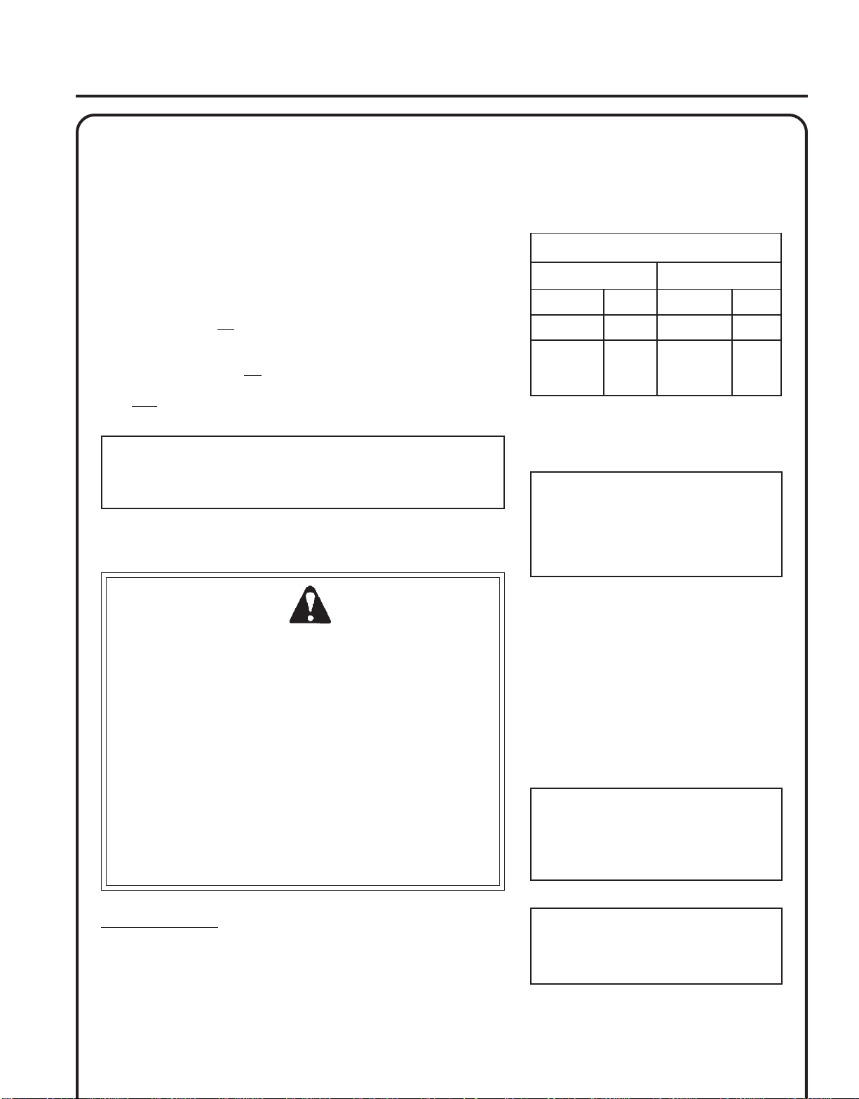
Fuel Requirements
Gasoline - Use 89 Octane [R+M/2] (mid grade or higher) gasoline
known to be good quality. Gasoline may contain up to 15% MTBE
(methyl tertiary-butyl ether). Gasohol containing methyl (wood) alcohol
is NOT approved.
EARTH AUGER
OPERATOR'S MANUAL
oitaR1:05-xiMliOotleuF
.S.UCIRTEM
11
Two Stroke Oil - A two-stroke engine oil meeting ISO-L-EGD (ISO/CD
13738) and J.A.S.O. FC Standards must be used. Echo brand premium
Power Blend
problems due to inadequate lubrication caused by failure to use an
ISO-L-EGD and J.A.S.O.
Blend
only are covered for two years, regardless of two-stroke oil used,
parts
per the statement listed in the Emission Defect Warranty Explanation.)
IMPORTANT
Echo premium Power Blend
at 50:1 ratio for application in all Echo engines sold in the past
regardless of ratio specified in those manuals.
TM
Universal 2-Stroke Oil meets these standards. Engine
TM
, will void the two-stroke engine warranty. (Emission related
FC certified oil, such as Echo premium Power
TM
Universal 2-Stroke Oil may be mixed
Handling Fuel
W ARNING
Fuel is VERY flammable. Use extreme care when mixing, storing or
handling or serious personal injury may result.
• Use an approved fuel container.
• DO NOT smoke near fuel.
• DO NOT allow flames or sparks near fuel.
• Fuel tanks/cans may be under pressure. Always loosen fuel caps
slowly allowing pressure to equalize.
• NEVER refuel a unit when the engine is HOT or RUNNING!
• DO NOT fill fuel tanks indoors. ALWAYS fill fuel tanks outdoors
over bare ground.
• DO NOT overfill fuel tank. Wipe up spills immediately.
• Securely tighten fuel tank cap and close fuel container after
refueling.
• Inspect for fuel leakage. If fuel leakage is found, do not start or
operate unit until leakage is repaired.
• Move at least 3m (10 ft.) from refueling location before starting
the engine.
DANGER
SAGLIOSAGLIO
snollaG.zo.lFretiL.cc
1
2
5
IMPORTANT
Spilled fuel is a leading cause of
hydrocarbon emissions. Some states
may require the use of automatic fuel
shut-off containers to reduce fuel
spillage.
After use
• DO NOT store a unit with fuel in its tank.
Leaks can occur. Return unused fuel to an
approved fuel storage container.
Storage - Fuel storage laws vary by locality.
Contact your local government for the laws
affecting your area. As a precaution, store
fuel in an approved, airtight container. Store
in a well-ventilated, unoccupied building,
away from sparks and flames.
IMPORTANT
Stored fuel ages. Do not mix more fuel
than you expect to use in thirty (30)
days, ninety (90) days when a fuel
stabilizer is added.
6.2
2.5
31
4
8
02
08
061
004
Mixing Instructions
1 . Fill an approved fuel container with half of the required amount of
gasoline.
2 . Add the proper amount of 2-stroke oil to gasoline.
3 . Close container and shake to mix oil with gasoline.
4 . Add remaining gasoline, close fuel container, and remix.
IMPORTANT
Stored two-stroke fuel may separate.
ALWAYS shake fuel container thoroughly before each use.
Page 12

12
STARTING COLD ENGINE
1 . Place auger on flat surface, recoil starter handle (A) up.
2. Stop Switch.
Move stop switch button (B) forward, away from the STOP
position.
3. Choke Lever
Move choke lever (C) to Cold Start Position (
4. Decompression Button
Press decompression button (D) once.
5. Primer
Pump primer bulb (E) until fuel is visible and flows freely in the
clear fuel tank return line. Pump bulb an additional 4 or 5 times.
6. Recoil Starter
Hold loop handle securely with one hand, and pull the recoil
starter handle (A) until engine fires (5 or 6 pulls). Do not hold
engine by the throttle grip handle. DO NOT depress throttle
trigger when starting.
7. Choke Lever
Move the choke lever to the OPEN - RUN position (
engine if necessary and allow to warm up at idle for several
minutes.
).
). Restart
A
B
D
C
NOTE
After engine starts, engine decompression button will automatically
reset for normal operation.
W ARNING DANGER
The auger attachment should not rotate at idle. If attachment
rotates, readjust carburetor according to "Carburetor Adjustment"
instructions in this manual or see your ECHO Dealer, otherwise
serious personal injury may result.
E
A
D
Page 13

STARTING WARM ENGINE
The starting procedure is the same as Cold Start, except DO NOT close
the choke.
W ARNING DANGER
When engine starts, the auger attachment may rotate, even with the
throttle trigger in idle (released) position.
1. Stop Switch
Move stop switch button (B) forward, away from the "STOP"
position.
2. Primer
Pump primer bulb (E) until fuel is visible in the "Clear" fuel return
line. Pump bulb an additional 4 or 5 times.
EARTH AUGER
OPERATOR'S MANUAL
B
E
13
3. Decompression Button
Press decompression button (D) once.
4. Recoil Starter.
Lay the unit on a flat, clear area, and pull the recoil starter handle
(A) until the engine fires.
NOTE
If engine does not start after 5 pulls, use Cold Start Procedure.
STOPPING ENGINE
1. Release Throttle.
Allow engine to return to idle before shutting off engine.
2. Stop Switch
Move stop switch button (B) backward to "STOP" position.
A
D
B
W ARNING DANGER
If engine does not stop when stop switch is moved to STOP
position, close choke - COLD START position - to stall engine.
Have your ECHO dealer repair stop switch before using unit again.
Page 14

14
DRILLING
1 . After starting engine, position auger upright at desired drilling
point.
2 . Position feet for a stable stance, away from auger blades.
3 . Firmly grip Throttle Handle Assembly and loop bar handle with
right and left hands.
4. Slowly squeeze throttle trigger to engage clutch and rotate auger.
Apply light downward pressure on handles to drill hole. Periodi-
cally, raise the auger to help clear drilling debris from the hole.
5 . Overloading the auger during drilling may cause it to stop turning.
When this occurs, lift the auger to reduce the drilling load on the
engine, and allow drilling debris to be augered out of the hole.
Resume drilling.
IMPORTANT
While drilling, the auger may twist suddenly and forcefully if it
contacts large rocks, roots, or other hidden obstacles. Release
throttle trigger immediately, and lift auger out of hole. Clear the
obstacles to prevent damage, and then resume drilling.
6 . Drilling holes six inches in diameter or larger may be easier if two
people hold the handles on opposite sides.
7 . Two-man Operation - The operator (A), guides the auger while
gripping the Throttle Handle Assembly and lower hand grip. The
helper (B), assists by guiding auger while gripping loop handle on
opposite side of auger.
8 . Do not place excessive body weight on the unit. Allow auger to drill
with a shaving action using light downward pressure.
9 . Do not use an ice auger in earth, or an earth auger in ice. A
different style of auger is required for each type of drilling.
10. Do not operate unit in excessively rocky ground.
TOP VIEW - 2-MAN AUGER OPERATION
BA
W ARNING DANGER
Never operate auger with handles above chest height, otherwise you could lose control, resulting in serious personal
injury.
W ARNING DANGER
During operation, the muffler or catalytic muffler and surrounding cover become hot. Always keep exhaust area clear
of flammable debris during use, otherwise serious property damage or personal injury may result.
Page 15

EARTH AUGER
OPERATOR'S MANUAL
MAINTENANCE
Your ECHO Auger is designed to provide many hours of trouble-free service. Regularly scheduled maintenance will help
your unit achieve that goal. To help you decide whether you want to do it yourself, or have the ECHO Dealer do it, the
skill level required for each maintenance task has been graded. If you are unsure, or are not equipped with the necessary
tools, you may want to take your unit to an ECHO Service Dealer for maintenance. The various part numbers required for
each task are listed below the task headings on the following pages. If a task is not listed, see your ECHO Dealer for
repairs. See your Echo dealer for all parts.
SKILL LEVELS
Level 1 = Easy to do. Most required tools come with unit.
Level 2 = Moderate difficulty. Some specialized tools may be required.
Level 3 = Experience required. Specialized tools are required. ECHO recommends that
the unit be returned to your ECHO dealer for servicing.
MAINTENANCE INTERVALS
15
/TNENOPMOC
METSYS
gnisuoHraeGesaerG 3 I
retliF
riAecalpeR/naelC/tcepsnI 1 C/I*R
ekohCnaelC/tcepsnI 2 C/I
retliFleuFecalpeR/tcepsnI 1 I*R
skael,metsySleuFecalpeR/tc
metsySgnilooCnaelC/tcepsnI 2 C/I
rotserrAkrapSrelffuMecalpeR/tcepsnI 2 C/I*R
epsnI 1 II *R/I*R
ECNANETNIAM
ERUDECORP
D'QER
LLIKS
LEVEL
ROYLIAD
EROFEB
ESU
YREVE
LEUFER
serudecorPecnanetniaMflesruoY-tI-oD
3
SHTNOM
09RO
SRUOH
serudecorPecnanetniaMrelaeDohcEdednemmoceR
6
SHTNOM
072RO
SRUOH
YLRAEY
006
SRUOH
* ..noitcepsnignirudraewroegamadfognidnifehtnodesaberaecalperotsnoitadnemmocerllA
epoRretratSlioceRnaelC/
gulPkrapSnaelC/tcepsnI 2 C/I*R
stloB/stuN/swercSecalpeR/nethgiT/tcepsnI 1 *R/I
-ETONTNATROPMI deriuqerfoycneuqerfehtenimretedlliwecneirepxeruoydnaesulaut
.ecnanetniam
tcepsnI 1 I*R/I
SEDOCRETTELERUDECORPECNANETNIAM NAELC=C,ECALPER=R,TCEPSNI=I:
cA.mumixameranwohsslavretniemiT
:SETONERUDECORPECNANETNIAM
Page 16

16
AIR FILTER
Level 1.
Tools required: 25 or 50 mm (1 or 2 in.) Cleaning brush
Parts required: Air Filters
1 . Close choke (Cold Start Position [
entering the carburetor throat when the air filters are removed.
Brush accumulated dirt from the air cleaner area.
2 . Unsnap the air filter cover latch(A), and open the air filter cover (B).
3 . Clean the foam filter in water/detergent solution. Wrap the foam
filter in a clean cloth and squeeze (do not wring) dry. Do not oil
foam filter. Lightly brush debris from felt filter.
NOTICE
If elements are fuel soaked, very dirty, deformed, or torn, replace,
otherwise engine damage may occur.
4. If elements can be cleaned and reused, be certain they:
•still fit the cavity in the air cleaner cover.
•are installed with the original side out.
]). This prevents dirt from
FUEL FILTER
Level 1.
Tools required: 200- 250 mm (8 - 10 in.) length of wire with one end
bent into a hook, clean rag, funnel, and an approved
fuel container.
B
D
C
A
Parts required: Fuel Filter
W ARNING DANGER
Fuel is VERY flammable. Use extreme care when mixing, storing or
handling.
1 . Use a clean rag to remove loose dirt from around fuel cap and
empty fuel tank.
2 . Use the “fuel line hook” to pull the fuel line and filter from the
tank.
3 . Remove the filter from the line and install the new filter.
Page 17

SPARK PLUG
Level 2.
Tools Required: Spark plug wrench, feeler gauge, soft metal brush.
Parts Required: RCJ-6Y Spark Plug, P/N15901731730
1 . Remove spark plug and check for fouling, worn and rounded
center electrode.
2 . Clean the plug or replace with a new one. DO NOT sand blast to
clean. Remaining sand will damage engine.
3. Adjust spark plug gap by bending outer electrode.
EARTH AUGER
OPERATOR'S MANUAL
17
4 . Install Spark Plug, and tighten to 150-170 kg/cm (130-150 in. lb.).
COOLING SYSTEM
Level 2.
Tools required: Air compressor and safety nozzle, or: 4 mm Hex
wrench, 25 - 50 mm (1 - 2 in.) cleaning brush.
Parts Required: None.
IMPORTANT
To maintain proper engine operating temperatures, cooling air
must pass freely through the cylinder fin area. This flow of air
carries combustion heat away from the engine.
Overheating and engine seizure can occur when:
• Air intakes are blocked, preventing cooling air from reaching the
cylinder.
• Dust and debris build-up on the outside of the cylinder. This build-up
insulates the engine and prevents the heat from leaving.
0.65 mm
(0.026 in.)
Removal of cooling passage blockages and cleaning of cooling fins is
considered “Normal Maintenance.” Any failure attributed to lack of
maintenance is not warranted.
1 . Periodically blow dirt and debris off cooling fins with a compressor
and safety nozzle, or;
2 . Remove engine and muffler covers, and brush off dirt and debris
using the medium bristle brush.
Page 18

18
EXHAUST SYSTEM
Spark Arrestor Screen
Level 2.
Tools Required: Cross Head Screwdriver, Soft Metal Brush, 4 mm
Hex Wrench
Parts Required: Spark Arrestor Screen, Gasket
1 . Remove muffler cover (A).
2 . Place piston at Top Dead Center (TDC) to prevent carbon/dirt from
entering cylinder.
3 . Remove spark arrestor screen cover (B), screen holder (C), gasket
(D), and screen (E), from muffler body.
4 . Clean carbon deposits from muffler components.
5 . Replace screen if it is cracked, plugged, or has holes burned
through.
6. Assemble components in reverse order.
Cylinder Exhaust Port
Level 3.
IMPORTANT
The cylinder exhaust port must be inspected and cleaned of excess
carbon every 3 months or 90 hours of operation to maintain this
engine within the emissions durability period. ECHO strongly
recommends that you return your unit to your ECHO dealer for this
important maintenance service.
A
DE
C
B
Page 19

CARBURETOR ADJUSTMENT
Engine Break-In
New engines must be operated a minimum duration of two tanks of fuel
break-in before carburetor adjustments can be made. During the break-in
period your engine performance will increase and exhaust emissions will
stabilize. Idle speed can be adjusted as required.
High Altitude Adjustment
High altitude adjustment is not required for proper operation of this
engine.
Level 2.
Tools required: Screwdriver, Tachometer (ECHO P/N 99051130017).
Parts required: None.
EARTH AUGER
OPERATOR'S MANUAL
19
NOTE
Every unit is run at the factory and the carburetor is set in compliance with emission regulations. This carburetor does not have
acceleration and high speed adjustment needles.
1. Check idle speed and reset if necessary. Idle speed screw (A)
should be set to the specifications found on page 22, "Specifications" of this manual. Turn idle screw (A) clockwise to increase idle
speed; counter-clockwise to decrease idle speed.
W ARNING DANGER
When carburetor adjustment is completed, the cutting attachment
should not turn at idle, otherwise serious personal injury may
result.
A
Page 20

20
TROUBLESHOOTING
melborPkcehCsutatSesuaCydemeR
TRAHCGNITOOHSELBUORTMELBORPENIGNE
ractaleuFroterubractaleufoNdeggolcreniartsleuF
roterub
deggolcenilleuF
roterubraC
rednilyctaleuFrednilyctaleufoNroterubraCrelaedohcEruoyeeS
FekohcnepO
leufhtiwtewrelffuMhcirooterutxiMleu
enignE
-sknarc
/drahstrats
t'nseod
trats
,snurenignE
roseidtub
tonseod
etarelecca
ylreporp
dnetakrapS
eriwgulpfo
gulptakrapSkrapsoNtce
retlifriAytridretlifriAraewlamroNecalper
retlifleuFytridretlifleuFseudiser/stnanimatnoCni
tnevleuFdeggulptnevleuFniseudiser/stnani
gulPkrapSnrow/ytridgulPraewlamroNecalperrotsujdadnanaelC
roterubraCtnemtsujdarepor
pmInoitarbiVtsujdA
krapsoNffohctiwspo
tS
melborplacirtcelE
hctiwskcolretnI
rrocnipagkrapS
nobrachtiwderevoC
leufhtiwdeluoF
evitcefedgulP
ecalpeR
leuf
matnoC
leuf
ecalperronaelC
ecalperronaelC
edohcEruoyeeS
rela
retlifriaecalper/naelC
roterubractsujdA
relaedohcEruoyeeS
NOothctiwsnruT
relaedohcEruoyeeS
relaedohcEruoyeeS
).ni620.0(mm56.ottsujdA
ecalperronaelC
rronaelC
ecalpe
gulpecalpeR
ronaelC
ecalperronaelC
metsySgnilooCmetsysgnilooC
deggulp/ytrid
serrAkrapS
rot
neercS
seodenignE
ton
knarc
A/NA/NmelborpenignelanretnIr
rotserrakrapS
deggulpneercs
raewlamroNecalpeR
ninoitarepodednetxE
snoitacolytsud/ytrid
naelC
WARNING DANGER
Fuel vapors are extremely flammable and may cause fire and/or explosion. Never test for ignition spark by
grounding spark plug near cylinder plug hole, otherwise serious personal injury may result.
elaedohcEruoyeeS
Page 21

STORAGE
Long Term Storage (over 30 days)
EARTH AUGER
OPERATOR'S MANUAL
21
W ARNING
During operation the muffler or catalytic muffler and surrounding cover become hot. Always keep exhaust area clear
of flammable debris during transportation or when storing, otherwise serious property damage or personal injury may
result.
Do not store your unit for a prolonged period of time (30 days or longer) without performing protective storage
maintenance which includes the following:
1 . Store unit in a dry, dust free place, out of the reach of children.
DANGER
W ARNING DANGER
Do not store in enclosure where fuel fumes may accumulate or reach an open flame or spark.
2. Place the stop switch in the "STOP" position.
3 . Remove accumulation of grease, oil, dirt, and debris
from exterior of unit and accessory augers.
4 . Perform all periodic lubrication and services that are
required.
5. Tighten all the screws and nuts.
6. Drain the fuel tank completely, and pull the recoil starter
handle several times to remove fuel from the carburetor.
7 . Remove the spark plug and pour 7 cc (1/4 oz.) of
fresh, clean, two-stroke engine oil into the cylinder
through the spark plug hole.
A. Place a clean cloth over the spark plug hole.
B . Pull the recoil starter handle 2-3 times to
distribute the oil inside the engine.
C. Observe the piston location through the
spark plug hole. Pull the recoil starter handle
slowly until the piston reaches the top of its
travel and leave it there.
8. Install the spark plug (do not connect ignition
cable).
Page 22

22
SPECIFICATIONS
MODELS --------------------------------------------- EA-400/EA-500
Length------------------------------------------------- 584 mm (23 in.)
Width-------------------------------------------------- 267 mm (10.5 in.)
Height ------------------------------------------------- 368 mm (14.5 in.)
Weight ------------------------------------------------ 9.75 kg (21.5 lb.)
Engine Type ------------------------------------------ Air cooled, two-stroke, single cylinder gasoline engine
Bore EA-400 ------------------------------------------ 40.0 mm (1.58 in.)
Bore EA-500 ------------------------------------------ 44.0 mm (1.73 in.)
Stroke-------------------------------------------------- 34.0 mm (1.34 in.)
Displacement EA-400 ------------------------------- 42.7 cc (2.61 cu. in.)
Displacement EA-500 ------------------------------- 51.7 cc (3.16 cu. in.)
Exhaust ------------------------------------------------ Spark Arrestor Muffler
Carburetor -------------------------------------------- Walbro diaphragm model w/purge pump
Ignition System -------------------------------------- Flywheel magneto, capacitor discharge (CDI)
Spark Plug -------------------------------------------- Champion RCJ-6Y, (Gap 0.65 mm (0.026 in.)
Fuel ---------------------------------------------------- Mixed (Gasoline and Two-stroke Oil)
Fuel/Oil Ratio ----------------------------------------- 50:1 two-stroke air cooled engine oil
Gasoline ----------------------------------------------- 89 Octane unleaded. DO NOT use fuel containing methyl alcohol, more
than 10% ethyl alcohol or 15% MTBE.
Oil ------------------------------------------------------ Power Blend TM Premium Universal 2-Stroke Oil
Fuel Tank Capacity ---------------------------------- 1.10 lit. (37.2 US fl. oz.)
Starter System ---------------------------------------- Automatic Recoil Starter
Clutch ------------------------------------------------- Centrifugal Type
Vibration Isolation System-------------------------- Cushioned left and right hand grips
PTO Shaft --------------------------------------------- 22 mm (.875 in.) Diameter
Gear Case Ratio -------------------------------------- 30.2:1 Reduction
Auger Capacity -------------------------------------- 51mm - 254 mm (2 in. - 10 in.)
Rotation ----------------------------------------------- Clockwise, viewed from top
Handle------------------------------------------------- Cushioned Bow w/Grip
Idle Speed--------------------------------------------- 2,800 - 3,200 RPM
Wide Open Throttle Speed (W.O.T.) -------------- 9,000 - 10,000 RPM
Page 23

EARTH AUGER
OPERATOR'S MANUAL
AUGER ACCESSORIES
Earth Augers* Part Number Description
99944900150 2" Earth Auger w/point
99944900160 3" Earth Auger w/point
99944900170 4" Earth Auger w/point
99944900180 6" Earth Auger w/point & Spring
99944900190 8" Earth Auger w/point & Spring
99944900200 10" Earth Auger w/point & Spring
Extension Shafts* 99944900210 18" Extension Shaft - 7/8" Diameter
99944900220 12" Extension Shaft - 7/8" Diameter
Earth Auger Replacement Blades* 99944900230 4" Replacement Blade - Earth Auger
99944900240 6" Replacement Blade - Earth Auger
99944900250 8" Replacement Blade - Earth Auger
99944900260 10" Replacement Blade - Earth Auger
99944900270 Replacement Point - Earth Auger
23
Ice Augers* 99944900280 8" Ice Auger - Dual Blade
99944900290 10" Ice Auger - Dual Blade
Ice Auger Replacement Blades* 99944900300 8" Replacement Blade - Ice Auger
99944900310 10" Replacement Blade - Ice Auger
Auger Adaptor 99944900335 Auger Adapter for 1" Auger mount
* All auger accessories include required assembly hardware.
Page 24

SERVICING INFORMA TION
P ARTS
Genuine ECHO Parts and ECHO REPOWER™ Parts and Assemblies for
your ECHO products are available only from an Authorized ECHO
Dealer. When you do need to buy parts always have the Model
Number and Serial Number of the unit with you. You can find these
numbers on the engine housing. For future reference, write them in the
space provided below.
Model No. _____________ SN. ____________
SERVICE
Service of this product during the warranty period must be performed
by an Authorized ECHO Service Dealer. For the name and address of
the Authorized ECHO Service Dealer nearest you, ask your retailer or
call: 1-800-432-ECHO (3246). Dealer information is also available on our
Web Site. When presenting your unit for Warranty service/repairs,
proof of purchase is required.
www.echo-usa.com
DEALER?
CALL
1-800-432-ECHO
OR
ECHO CONSUMER PRODUCT SUPPORT
If you require assistance or have questions concerning the application,
operation or maintenance of this product you may call the ECHO
Consumer Product Support Department at 1-800-673-1558 from 8:30 am
to 4:30 pm (Central Standard Time) Monday through Friday. Before
calling, please know the model and serial number of your unit to help
your Consumer Product Support Representative.
CONSUMER PRODUCT
SUPPORT
1-800-673-1558
8:30 - 4:30 MON - FRI C.S.T.
WARRANTY REGISTRATION
You may register your Echo equipment using the warranty registration
card or register on-line at www.echo-usa.com. Registering provides a
direct link between you and ECHO if we find it necessary to contact
you.
ADDITIONAL OR REPLACEMENT MANUALS
Safety Manuals in English/Spanish or English/French are available, free of charge, from your ECHO dealer or at
www.echo-usa.com.
Operator's and Parts Manuals are available by:
• Downloading free from www.echo-usa.com
• Purchasing from your Echo Dealer.
• Manuals are available by sending a written request stating the model number and serial number of your Echo unit,
part number of the manual, your name and address, and mail to the address below.
ECHO, INCORPORATED
400 OAKWOOD ROAD
LAKE ZURICH, IL 60047
www.echo-usa.com
(EA-400) 03001001/0399999
(EA-500) E02103001001/E02103999999
 Loading...