

Page 1
Instructions
PRODUCT: ELECTRONIC FEED
KIT (PN 74898-00)
FITS MODEL: CH9540H (72854)
SERIAL NUMBER 803703 & BELOW
WARNING
BEFORE INSPECTING OR SERVICING ANY PART
OF THIS MACHINE, SHUT OFF POWER SOURCE,
DISCONNECT SPARK PLUG WIRE FROM SPARK
PLUG AND MAKE SURE ALL MOVING PARTS HAVE
COME TO A COMPLETE STOP.
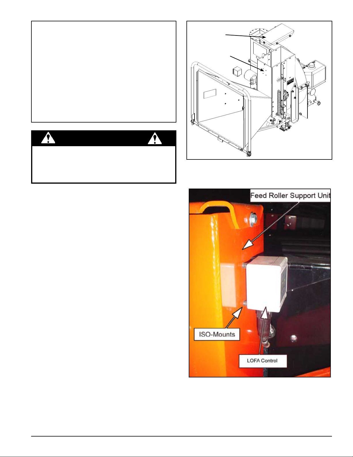
MOUNTING THE LOFA CONTROL
TOP COVER
FOUR 1/4" HOLES
Figure 1
Remove the drive shaft joint shield ring.1.
Remove upper belt guard.2.
Remove the top cover from the Feed Roller Support 3.
unit. If the serial number is equal to or greater than
X01249, skip to STEP 7 (Figure 1).
Remove the back cover from the LOFA control, center it 4.
3-1/2” from the top on the front plate of the Feed Roller
Support housing and mark the position of the holes.
Drill four 1/4” holes (Figure 1).5.
Attach the ISO-Mounts to the controller back plate with 6.
the bolts and nuts provided (Figure 2).
Secure the back plate of the controller to the Feed 7.
Roller Support housing with a washer and one M4-
0.7 nut per bolt. Apply thread locking adhesive and
tighten.
Replace the Feed Roller Support cover.8.
Attach the LOFA Control to the back plate (Figure 2)9. .
Instruction Sheet
Figure 2
PN 74916-00
Rev. 010508
Page 2
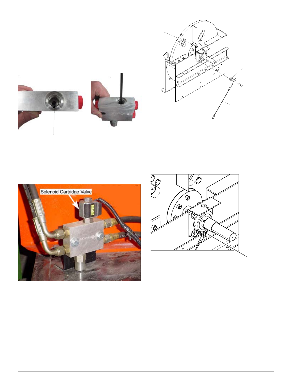
INSTALLING THE SOLENOID
SENSOR
BOLT, 1/2 X 2 HEX
SENSOR BRACKET
NUT, 1/2 CENTERLOCK
1/8" - 1/16"
GAP
CARTRIDGE VALVE
Remove outer plug (using 5/16" allen wrench) from the 1.
top of the valve manifold.
Once the outer plug has been removed, using a 3/16 2.
allen wrench, extract the inner plug located in the relief
valve (Figure 3).
Figure 5
INSTALLING THE SENSOR
Figure 3, 3/16" inner plug
Replace the removed components with the new sole-3.
noid cartridge valve and coil.
Connect solenoid wiring to LOFA Control wiring har-4.
ness (Figure 4).
Figure 3
Secure the sensor bracket with the lower left bearing 1.
bolt and position it (the sensor) so it aligns with the set
bolt (Figure 5).
POSITIONING THE SENSOR
Position the sensor approximately 1/16” - 1/8” from the 1.
head of the bolt (Figure 6).
Replace the belt guard weldment using 5/16” hard-2.
ware.
Figure 6
ELECTRICAL INSTALLATION
Attach the chipper to the tractor. Connect the RED 1.
positive lead to a +12 Volt DC power source on the
tractor.
Connect the BLACK negative lead to a grounding 2.
source on the tractor.
Drill a 3/16" hole in the PTO stand, close to the 3.
solenoid valve, and secure the ground wire with the #10
self-tapping screw provided.
Connect the two-pin connector to the top of the valve 4.
coil.
Connect the socket connector to the LOFA control.5.
Secure the wiring harness with cable ties as appropriate.6.
Instruction Sheet
Page 3

FEED SENSOR PROGRAMMING
INSTRUCTIONS
STEP 1. INITIATING PROGRAM MODE
Hold down the “S” button while turning the engine key to
the “on” position until “L” starts to flash on the LCD.
STEP 6. ENTER NUMBER OF POLES
(IPU=NUMBER OF POLES
The number of poles is used to indicate the number of
speed pickup devices.
Press the arrow until (1) is displayed.1.
Push the "S" button once to save.2.
STEP 2. ENTER LOW (L = LOW) RPM
The low setting is the RPM speed where the feed roller
stops. The “up” arrow increases the RPM setting, while
the “down” arrow decreases the RPM setting. Setting the
speed lower causes the engine to lug down more before
the feed roller stops.
Hold the appropriate (either up or down) arrow until 1.
the desired RPM speed is displayed (recommend ed
setting is 1375 rpm).
Push the “S” button once to save.2.
NOTE: Do not choose a setting equal to or below zero.
STEP 3. ENTER NORMAL
(N = NORMAL) RPM
The normal setting is the RPM speed that the chipper rotor
usually rotates.
Hold the appropriate (either up or down) arrow until 1.
the desired RPM speed is displayed (recommended
setting is 1500 rpm).
Push the “S” button once to save.2.
STEP 4. ENTER HIGH (H = HIGH) RPM
The high setting is not needed with this application.
Set to zero to deactivate.1.
Push the “S” button once with zero displayed to 2.
save.
DISPLAY CODES
When "DAY" is displayed, this will indicate the total number
of hours the machine has been operated since it was reset
by the operator. To reset the DAY hours:
When DAY is flashing, hold the "S" button down until 1.
the display reads 0 (zero).
To see the total number of operating hours for the machine,
press the "S" button once. The total number of operating
hours on the machine will be displayed. This number
cannot be reset.
WARNING
NOTE: WHEN APPROACHING THE END OF A LOG, IT
MIGHT BE NECESSARY TO MANUALLY OVERRIDE
THE AUTOMATIC FEED SENSOR. BE SURE TO PAY
ATTENTION TO THE ENGINE SPEED AND FEEDING
OF THE MATERIAL.
ELECTRONIC FEED PARTS LIST (PN 74898-00)
ITEM
1 12674
2 15225
3 15602 WASHER, #6 SAE FLAT 4
PART
NUMBER
DESCRIPTION QTY
CONTROL, LOFA
HYDRAULIC
SCREW, #10 X 3/4 HEX
TAP SC
1
2
STEP 5. ENTER RETURN
(RET = RETURN) RPM
The return setting is the RPM speed at which the feed
roller restarts. The feed roller should restart before the
rotor reaches “normal” RPM to maximize chipper efficiency.
Setting the speed higher allows the engine to recover more
before the feed roller restarts.
Hold the appropriate (either up or down) arrow until 1.
the desired RPM speed is displayed (recommended
setting is 1400 rpm).
Instruction Sheet
4 15640 NUT, M4-0.7 ZP HEX 8
5 16967
6 16968 COIL, SOLENOID VALVE 1
7 17320 STRAP, NYLON TIE-11” 4
8 18022-00 HARNESS, 8” PTO LOFA 1
9 73242-12
VALVE, SOLENOID
CARTRIDGE
BRACKET, PROXIMITY
SENSOR
1
1
Page 4

1
8
5
6
2
7
4
3
9
5
6
4
2
3
1
WIRE COLOR CODE LEGEND
O ORANGE
G GREEN
B BLACK
R RED
BL BLUE
BR BROWN
B
O
G
BR
B
PROXIMITY
SENSOR
B
BL
BR
7
BL
R
FUSE
8 AMP
R
POWER GROUND
B
COIL
CONN
CONN
O G
ECHO BEAR CAT
www.bearcatproducts.com
237 NW 12th Street, West Fargo, ND 58078-0849
Phone: 701.282.5520 • Toll Free: 800.247.7335 • Fax: 701.282.9522
E-mail: service@bearcatproducts.com • sales@bearcatproducts.com
Instruction Sheet
 Loading...