

Page 1

GT Split Boom Cultivator Attachment
99944200500
SRM Split Boom Cultivator Attachment
Pro Series Attachment
TM
99944200510
Operator's Manual
MODELS USED ON: GT-2000SB Type 1/1E
SRM-2100SB/2400SB
SRM-210SB/211SB
SRM-251SB
SRM-260SB/261SB
PAS 2100/2400
PAS 210/211
PAS 230/231
PAS 260/261
Read rules for safe operation and instructions carefully. ECHO provides an Operator's
Manual and a Safety Manual, with your original Split Boom Trimmer or Pro Attachment
SeriesTM. Those manuals and this manual must be read and understood for proper and
safe operation.
X7502232403
PAS-2601
W ARNING DANGER
89865062133
01/06
Page 2
2
INTRODUCTION
Welcome to the ECHO family. This ECHO product was designed and manufactured to provide long life and on-thejob-dependability. Read and understand this manual included with your attachment. You will find this manual easy to
use and full of helpful operations tips and SAFETY messages.
THE OPERATOR'S MANUAL
Contains specifications and information for operation, starting,
stopping, maintenance, storage and assembly specific to this product.
TABLE OF CONTENTS
Introduction ...............................................................2
- The Operator's Manual .......................................2
Safety .........................................................................3
- Manual Safety Symbols & Important Information3
- International Symbols .........................................3
- Personal Condition and Safety Equipment.......... 3
- Equipment ..............................................................6
Description ................................................................6
Contents ....................................................................7
Assembly ................................................................... 7
- Power Head Shaft/Lower Shaft Assembly ..........7
Operation ...................................................................8
- Resetting Tines for Deep Cultivation ................ 10
CopyRight© 2006 By Echo, Incorporated
All Rights Reserved.
Maintenance ............................................................ 11
- Skill Levels ........................................................ 11
- Maintenance Intervals ......................................11
- Lubrication ........................................................ 12
Storage..................................................................... 1 3
Specifications........................................................... 13
Servicing Infor mation............................................... 1 6
- Parts/Serial Number ........................................... 16
- Service............................................................... 16
- ECHO Consumer Product Support .................... 1 6
- Warranty Registration....................................... 16
- Additional or Replacement Manuals................. 1 6
Specifications, descriptions and illustrative material in this
literature are as accurate as known at the time of publication, but are subject to change without notice. Illustrations
may include optional equipment and accessories, and may
not include all standard equipment.
Page 3
GT/SRM SPLIT BOOM/PAS CULTIVATOR ATTACHMENT
SAFETY
MANUAL
Throughout this manual and on the product itself, you will find safety
alerts and helpful, informational messages preceded by symbols or key
words. The following is an explanation of those symbols and key
words and what they mean to you.
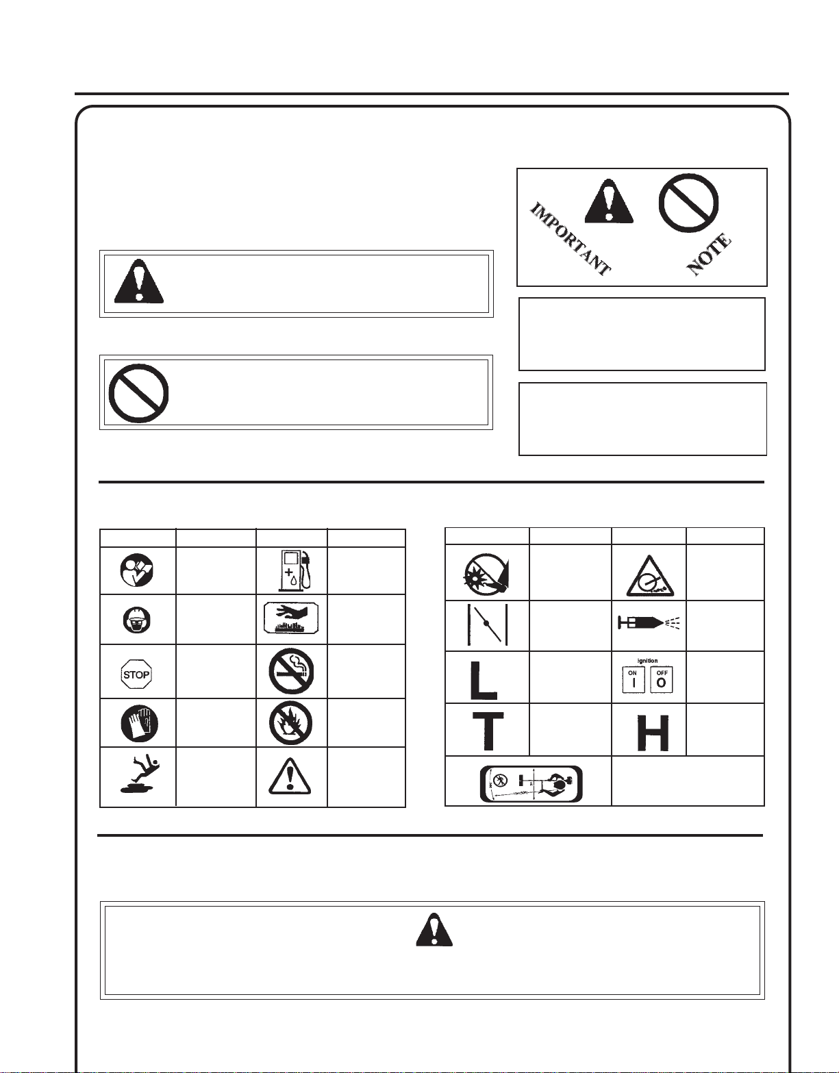
SAFETY SYMBOLS AND IMPORTANT INFORMATION
This symbol accompanied by the words WARNING and
DANGER calls attention to an act or condition that can lead
to serious personal injury to operator and bystanders.
The circle with the slash symbol means whatever is shown
within the circle is prohibited.
OPERATOR'S MANUAL
IMPORTANT
The enclosed message provides
information necessary for the protection of the unit.
NOTE
This enclosed message provides tips
for use, care and maintenance of the
unit.
3
INTERNA TIONAL SYMBOLS
Symbol form/shape
Symbol
description/application
Read and
understand
Operator's Manual.
Wear eyes, ears
and head
protection
Emergency stop
Wear hand
protection. Use
two handed.
Wear slip
resistant foot
wear.
Symbol form/shape
Symbol
description/application
Fuel and oil
mixture
Hot
Surface
DO NOT smoke
near fuel.
DO NOT allow
flames or sparks
near fuel.
Safety/Alert
Symbol form/shape
PERSONAL CONDITION AND SAFETY EQUIPMENT
Symbol
description/application
Keep feet away
from rotaing
attachment
Engine choke
control.
Carburetor
adjustment
- Low speed mixture
Carburetor
adjustment
- Idle speed
Symbol form/shape
- High speed mixture
Keep bystanders and helpers
away 15 m (50 ft.).
Symbol
description/application
Thrown objects
Primer bulb
Ignition
ON/OFF
Carburetor
adjustment
W ARNING DANGER
Cultivator users risk injury to themselves and others if the cultivator is used improperly and or safety precautions
are not followed. Proper clothing and safety gear must be worn when operating a cultivator.
Page 4
4
Physical Condition
Your judgment and physical dexterity may not be good:
• if you are sick,
• if you are taking medication,
• if you have taken alcohol or drugs.
Operate unit only if you are physically and mentally well.
Eye Protection
Wear eye protection that meets ANSI Z87.1 or CE requirements whenever you operate the unit.
Hand Protection
Wear no-slip, heavy duty work gloves to improve your grip on the handles. Gloves also reduce the transmission of
machine vibration to your hands.
Hearing Protection
ECHO recommends wearing hearing protection whenever unit is used.
Proper Clothing
Wear snug fitting, durable clothing;
• Pants should have long legs, shirts with long sleeves.
• Wear hair covering to contain long hair.
• DO NOT WEAR SHORTS,
• DO NOT WEAR TIES, SCARFS, JEWELRY.
Wear sturdy work shoes with non-skid soles;
• DO NOT WEAR OPEN TOED SHOES,
• DO NOT OPERATE UNIT BAREFOOTED.
Hot Humid Weather
Heavy protective clothing can increase operator fatigue which may lead to heat stroke. Schedule heavy work for early
morning or late afternoon hours when temperatures are cooler.
Vibration and Cold --
It is believed that a condition called Raynaud’s Phenomenon, which affects the fingers of certain individuals may be
brought about by exposure to vibration and cold. Exposure to vibration and cold may cause tingling and burning sensations followed by loss of color and numbness in the fingers. The following precautions are strongly recommended
because the minimum exposure which might trigger the ailment is unknown.
• Keep your body warm, especially the head, neck, feet, ankles,
hands and wrists.
• Maintain good blood circulation by performing vigorous arm
exercises during frequent work breaks and also by not smoking.
• Limit the hours of operation. Try to fill each day with jobs where
operating the unit or other hand-held power equipment is not
required.
• If you experience discomfort, redness, and swelling of the fingers
followed by whitening and loss of feeling, consult your physician
before further exposing yourself to cold and vibration.
Page 5

GT/SRM SPLIT BOOM/PAS CULTIVATOR ATTACHMENT
OPERATOR'S MANUAL
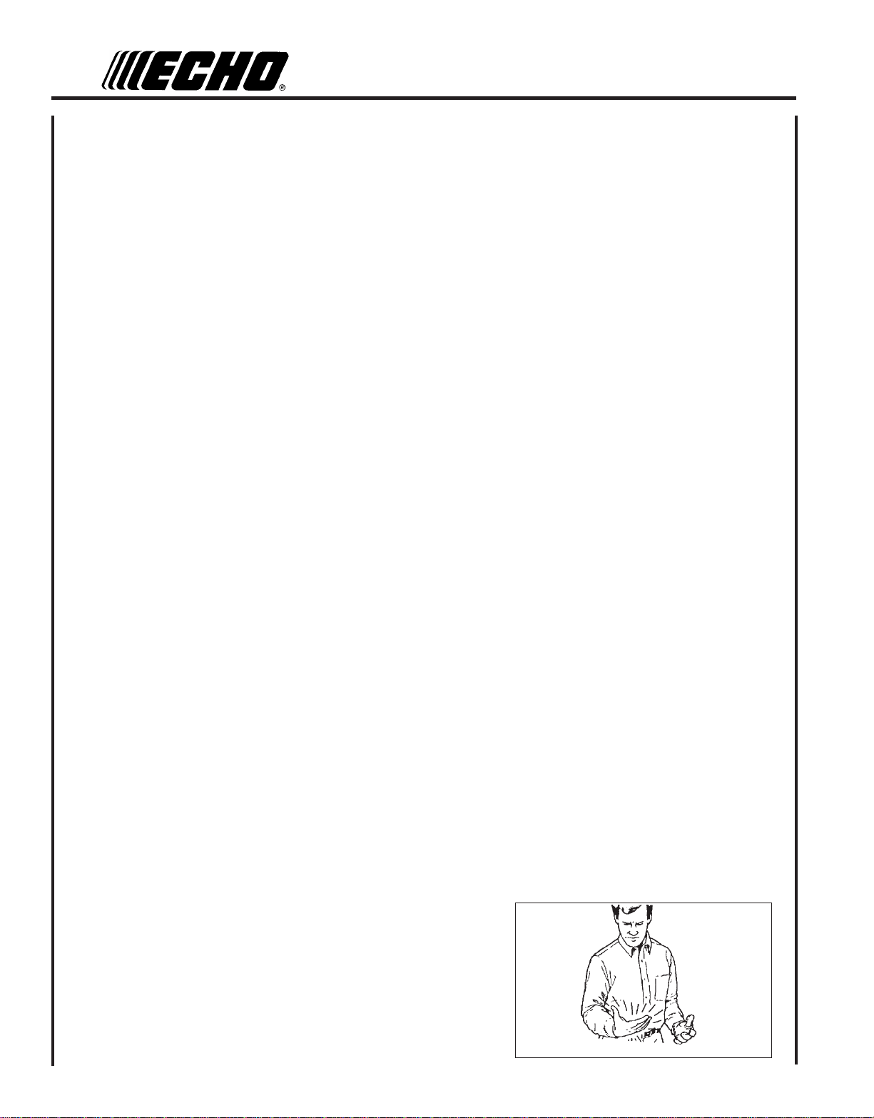
Repetitive Stress Injuries --
It is believed that overusing the muscles and tendons of the fingers, hands, arms, and shoulders may cause soreness,
swelling, numbness, weakness, and extreme pain in those areas. Certain repetitive hand activities may put you at a high
risk for developing a Repetitive Stress Injury (RSI). An extreme RSI condition is Carpal Tunnel Syndrome (CTS), which
could occur when your wrist swells and squeezes a vital nerve that runs through the area. Some believe that prolonged
exposure to vibration may contribute to CTS. CTS can cause severe pain for months or even years.
To reduce the risk of RSI/CTS, do the following:
• Avoid using your wrist in a bent, extended or twisted position.
Instead try to maintain a straight wrist position. Also, when
grasping, use your whole hand, not just the thumb and index finger.
• Take periodic breaks to minimize repetition and rest your hands.
• Reduce the speed and force in which you do the repetitive movement.
• Do exercises to strengthen the hand and arm muscles.
• See a doctor if you feel tingling, numbness or pain in the fingers,
hands, wrists or arms. The sooner RSI/CTS is diagnosed, the more
likely permanent nerve and muscle damage can be prevented.
5
W ARNING DANGER
Do not operate this product indoors or in inadequately ventilated
areas. Engine exhaust contains poisonous emissions and can
cause serious injury or death.
Read the Manuals
• Provide all users of this equipment with the Operator’s Manual and
Safety Manual for instructions on Safe Operation.
Clear the Work Area
• Spectators and fellow workers must be warned, and children and
animals prevented from coming nearer than 15 m (50 ft.) while the unit
is in use.
Keep a Firm Grip
• Hold the front and rear handles with both hands, with thumbs and
fingers encircling the handles.
Keep a Solid Stance
• Maintain footing and balance at all times. Do not stand on slippery,
uneven or unstable surfaces. Do not work in odd positions or on
ladders. Do not over reach.
Cutting Angle Adjustments
• Only adjust cutting blade angle with unit flat on the ground, with the
engine stop switch in the “STOP” position. Never adjust cutting
angle with unit standing upright.
Avoid Hot Surfaces
• Keep exhaust area clear of flammable debris. Avoid contact during
and immediately after operation.
Page 6

6
EQUIPMENT
W ARNING DANGER
Use only ECHO approved attachments. Serious injury may result from the use of a non approved attachment combination. Read and comply with all safety instructions listed in this manual and safety manual. ECHO, INC. will not be
responsible for the failure of cutting devices or accessories which have not been tested and approved by ECHO for
use with this unit.
Before operation a complete check of the unit must be performed;
• Check unit for loose/missing nuts, bolts and screws. Tighten and/or replace as needed.
• Inspect shield for damage and is securely in place. Replace if shield is damaged or missing.
• Check that the cutting tines are firmly attached and in safe operating condition.
• The cultivator gear housing is designed for ECHO recommended tines. Do not modify the gear housing for any other
purpose or replace tines with other type or size.
Parts
• Do not use cultivator attachment if any part is missing or damaged.
• Have repairs done only by an authorized ECHO Service dealer.
• Do not use any attachment, accessory or replacement part unless it is recommended in this Operator's Manual.
DESCRIPTION
Locate this safety decal on your unit. Make sure the decals are legible and that you understand and follow the instructions. If the decal cannot be read, a new one can be ordered from your ECHO Dealer. See PARTS ORDERING instructions
for specific information.
P/N 89016025560
7
1
6
2
4
3
4
5
Page 7

GT/SRM SPLIT BOOM/PAS CULTIVATOR ATTACHMENT
OPERATOR'S MANUAL
1. DRIVE SHAFT ASSEMBLY - Contains a specially designed liner and the flexible drive shaft.
2. SHIELD - Attached to deflect debris away from operator and reduce accidental contact with tines.
3. HUB - Separately attached to axle ends by clevis pin and spring pin. Tines bolt to hubs.
4. TINES - Identical on right and left side from operator's position. See page 12 for optional settings.
5. GREASE ACCESS BOLT - Apply lithium grease with grease gun to gear housing every 30 hours of use.
6. GEAR HOUSING - Houses gears and ball bearings for driving tines.
7. SERIAL NUMBER LABEL - Also serves as insertion line when drive shaft is properly engaged.
CONTENTS
The ECHO product you purchased has been factory pre-assembled for your convenience. After opening the carton,
check for damage. Immediately notify your retailer or ECHO Dealer of damaged or missing parts. Use the contents list to
check for missing parts.
7
1 - Split Boom Cultivator Attachment
- Plastic Bag (co-pack)
- Operator's Manual
- Warranty Registration Card
- Storage Hook Assembly
- Safety Glasses
ASSEMBLY
POWER
Tools Required: None
Parts Required: PAS or SRM-SB Power Head w/Shaft & Coupling.
1 . Set Power Head/Shaft Assembly on a level surface.
HEAD SHAFT/LOWER SHAFT ASSEMBL Y
B
D
2 . Pull locator pin (A) out, and turn counter-clockwise 1/4 turn to
lock-out position.
3 . Remove vinyl cap from attachment drive shaft.
A
Page 8

8
4 . Carefully fit attachment drive shaft assembly into coupler (B) to
decal assembly line (C), making sure that the inner lower drive shaft
engages into the square upper drive shaft socket.
NOTE
Earlier model Power Heads may have shorter couplings. Short
couplings fit flush to decal point (E). New couplings are 4-3/4 in.
long, and fit flush to line (C).
NOTE
Lower bearing housing and head assembly must be in line with the
engine.
5 . Rotate locator pin (A) 1/4 turn clockwise to engage lower shaft
hole. Insure locator pin is fully engaged by twisting lower drive
shaft. Locator pin should snap flush in coupler. Full engagement
will prevent further shaft rotation.
D
C
6 . Secure lower shaft assembly to coupler by tightening clamping
knob (D).
OPERATION
NOTE
Refer to your Split Boom Operator's Manual for correct engine
fueling, starting and stopping instructions.
W ARNING DANGER
• When engine starts tines may rotate. Warn fellow workers and
keep children and pets from coming nearer than 4.5 m (15 ft.).
• Always operate cultivator with both hands.
• Always stop engine when transporting unit to or between work
areas.
• Do not perform maintenance procedures, unclog or clean cultivator tines while engine is running.
• Do not operate the cultivator above ground level or near feet.
• Do not allow the tines to contact large obstructions which may
cause kickback and loss of control.
• Failure to follow these warnings may result in serious injury.
E
Page 9

GT/SRM SPLIT BOOM/PAS CULTIVATOR ATTACHMENT
Operating Techniques
1 . The tilling width of the cultivator is approximately 165 mm (6.5 in.).
Place cultivator in area to be tilled, hold unit firmly with left hand on
front grip and right hand on rear grip and gradually engage throttle
trigger. Guide the cultivator allowing the tines to pull forward. The
soil hardness will control tilling speed.
2 . The cultivator attachment is capable of tilling in the forward or
reverse direction. For deep soil tilling, till forward then lightly pull
unit rearward allowing the tines to make a deeper cut into the soil.
Deep soil cultivating can also be enhanced by repositioning the
tines. (Refer to Tine Setting).
OPERATOR'S MANUAL
9
3 . To raise or aerate the soil, tilt engine closer to the ground which will
raise cultivator tines higher relative to the soil surface.
IMPORTANT
Do not operate cultivator underwater. The gear housing is not
sealed and water will wash away lubrication damaging gears,
bearings, and seals.
Page 10

10
RESETTING TINES FOR DEEP CULTIVATION
Tools Required: 10 mm Wrench
The tines are factory assembled with blade ends offset for standard
cultivation. For deep cultivation, the left tine (viewed from the operator's
position) must be repositioned on the hub aligning the left and right tine
blade ends directly across from each other.
1 . Remove three (3) bolts (A) mounting left tine to hub. The bolts will
be mounted in hole labeled (1).
2 . Rotate tine counter clockwise and position hole labeled (2) over
hub mounting holes. The tine blade ends should be aligned
directly opposite each other.
3. Install and tighten bolts.
A
Page 11

GT/SRM SPLIT BOOM/PAS CULTIVATOR ATTACHMENT
OPERATOR'S MANUAL
11
MAINTENANCE
Your ECHO cultivator is designed to provide many hours of trouble free service. Regular scheduled maintenance will help
your cultivator achieve that goal. If you are unsure or are not equipped with the necessary tools, you may want to take
your unit to an ECHO Service Dealer for maintenance. To help you decide whether you want to DO-IT-YOURSELF or
have the ECHO Dealer do it, each maintenance task has been graded. If the task is not listed, see your ECHO dealer for
repairs.
SKILL LEVELS
Level 1 = Easy to do. Most required tools come with unit.
Level 2 = Moderate difficulty. Some specialized tools may be required.
Level 3 = Experience required. Specialized tools are required. ECHO recommends
the unit be returned to your ECHO Dealer for service.
ECHO offers REPOWER Maintenance Kits and Parts to make your maintenance job easier. Below each task heading are
listed the various part numbers required for that task. See your ECHO dealer for these parts.
MAINTENANCE INTERVALS
metsyS/tnenopmoCecnanetniaM
tfahSevirDesaerG ]1[
gnisuoHraeGesaerG
seniT/gnisuoHraeGnaelC
stloB,stuN,swercS,nethgiT,tcepsnI
ecalpeR
-TNATROPMI ehteni
]1[ eb
]2[ ebuLohcEylppA
MT
uLohcEylppA
MT
erofeB
erudecorP
.ecnanetniamderiuqerfoycneuqerf
.esufosruoh52yreve
.esufosruoh03yreve
esu
•
yrevE
leufeR
yrevEroyliaD
sruoh4
•
52
sruoh
mretedlliwecneirepxeruoydnaesulautcA.mumixameranwohsslavretniemiT
03
sruoh
]2[
Page 12

12
LUBRICA TION
Gear Housing
Level 2
Tools Required: 10 mm wrench, 13 mm wrench, grease gun, lithium
grease, clean rag.
Parts required: Echo Lube
NOTE
Clean cultivator with damp rag before lubricating gear housing.
1 . Loosen two (2) 10 mm upper gear housing bolts (A) and remove
gear housing. Shield will remain on drive shaft.
2 . Remove 13 mm bolt (B).
Apply grease until grease can be seen coming through ball
bearings in gear case bore.
3 . Install 13 mm bolt (B), assemble gear housing onto drive shaft
correctly matching gear housing to shield cutout (C), and tighten
10 mm bolts (A).
TM
8 oz. (P/N 91014) or Lithium Base Grease
Drive Shaft (Lower)
IMPORTANT
Lower drive shaft must be lubricated with high temperature
automotive grease every 25 hours of operation, otherwise drive
shaft assembly overheating and failure can result.
A
C
A
B
E
1 . Loosen clamping knob (D).
2 . Pull locator pin (E) and rotate 1/4 turn counter clockwise to lockout
position.
3 . Remove lower drive shaft housing.
4 . Remove lower flex cable, wipe clean and re-coat cable with thin
coating of 1/2 oz. (15 ml) of grease.
5 . Install cable. Carefully fit lower drive shaft assembly into coupler
(F) to decal assembly line (G) making sure inner lower flex cable
engages into the upper drive shaft mount.
D
F
G
Page 13

GT/SRM SPLIT BOOM/PAS CULTIVATOR ATTACHMENT
STORAGE
1 . Clean cultivator attachment.
IMPORTANT
Do not immerse this attachment in water. Water will enter gear
housing and damage gears, bearings and seals.
2. Apply thin coating of oil to metal parts to prevent rust.
3 . Lubricate lower shaft assembly with lithium grease.
4. Store hedge clipper attachment in a dry, dust free place out of the
reach of children, using supplied storage hook.
OPERATOR'S MANUAL
13
Storage Hook Installation
1 . Insert small end of hook into locating hole on attachment shaft.
2. Slide plastic cap onto end of attachment shaft.
SPECIFICATIONS
LEDOM DNAROTAVITLUCMOOBTILPSMRS/TG
htgneL ).ni53(mm998
htdiW ).ni5.6(mm561
thgieH ).ni5.8(mm612
retemaiDedalB ).ni0.8(mm302
htdiWgnitavitluC ).ni52.6(mm951
TNEMHCATTASAP
thgieW ).bl65.4(gk70.2
eroBgnitnuoMrotavitluC ).
eloHerauqSgnilpuoC ).ni12.0x12.0(mm4.5x4.5
oitaRnoitcudeRraeG1:51.64
noitacirbuL ebuLohcE
ni89.0(mm0.52
MT
Page 14

14
NOTES
Page 15

GT/SRM SPLIT BOOM/PAS CULTIVATOR ATTACHMENT
OPERATOR'S MANUAL
NOTES
15
Page 16

SERVICING INFORMATION
PARTS
Genuine ECHO Parts and ECHO REPOWER™ Parts and Assemblies for
your ECHO products are available only from an Authorized ECHO
Dealer. When you do need to buy parts always have the Model
Number and Serial Number of the unit with you. You can find these
numbers on the engine housing. For future reference, write them in the
space provided below.
/SERIAL NUMBER
Model No. _____________ SN. ____________
SERVICE
Service of this product during the warranty period must be performed
by an Authorized ECHO Service Dealer. For the name and address of
the Authorized ECHO Service Dealer nearest you, ask your retailer or
call: 1-800-432-ECHO (3246). Dealer information is also available on our
Web Site. When presenting your unit for Warranty service/repairs,
proof of purchase is required.
ECHO CONSUMER PRODUCT SUPPORT
If you require assistance or have questions concerning the application,
operation or maintenance of this product you may call the ECHO
Consumer Product Support Department at 1-800-673-1558 from 8:30 am
to 4:30 pm (Central Standard Time) Monday through Friday. Before
calling, please know the model and serial number of your unit to help
your Consumer Product Support Representative.
DEALER?
Call
1-800-432-ECHO
www.echo-usa.com
CONSUMER PRODUCT
SUPPORT
1-800-673-1558
8:30 - 4:30 Mon - Fri C.S.T.
WARRANTY REGISTRATION
You may register your Echo equipment using the warranty registration
card or register on-line at www.echo-usa.com. Registering provides a
direct link between you and ECHO if we find it necessary to contact
you.
ADDITIONAL OR REPLACEMENT MANUALS
Safety Manuals in English/Spanish or English/French are available, free of charge, from your ECHO dealer or at
www.echo-usa.com.
Operator's and Parts Manuals are available by:
• Downloading free from www.echo-usa.com
• Purchasing from your Echo Dealer.
• Manuals are available by sending a written request stating the model number and serial number of your Echo unit, part
number of the manual, your name and address, and mail to the address below.
Safety Videos are available from your Echo dealer. A $5.00 shipping charge will be required for each video.
ECHO, INCORPORATED
400 O
AKWOOD ROAD
LAKE ZURICH, IL 60047-1564
www.echo-usa.com
001001/999999
 Loading...