

Page 1

SmartServer 2.2
User’s Guide
078-0345-01F
Page 2

Echelon, LON, LONWORKS, LonTalk, Neuron, LONMARK,
3120, 3150, LNS, LonMaker, and the Echelon logo are
trademarks of Echelon Corporation registered in the
United States and other countries. LonPoint and
LonSupport are trademarks of Echelon Corporation.
Other brand and product names are trademarks or
registered trademarks of their respective holders.
Smart Transceivers, Neuron Chips, and other OEM
Products were not designed for use in equipment or
systems which involve danger to human health or safety
or a risk of property damage and Echelon assumes no
responsibility or liability for use of the Smart Transciever or
Neuron Chips in such applications.
Parts manufactured by vendors other than Echelon and
referenced in this document have been described for
illustrative purposes only, and may not have been tested
by Echelon. It is the responsibility of the customer to
determine the suitability of these parts for each
application.
ECHELON MAKES NO REPRESENTATION, WARRANTY, OR
CONDITION OF ANY KIND, EXPRESS, IMPLIED, STATUTORY,
OR OTHERWISE OR IN ANY COMMUNICATION WITH YOU,
INCLUDING, BUT NOT LIMITED TO, ANY IMPLIED
WARRANTIES OF MERCHANTABILITY, SATISFACTORY
QUALITY, FITNESS FOR ANY PARTICULAR PURPOSE,
NONINFRINGEMENT, AND THEIR EQUIVALENTS.
No part of this publication may be reproduced, stored in
a retrieval system, or transmitted, in any form or by any
means, electronic, mechanical, photocopying,
recording, or otherwise, without the prior written
permission of Echelon Corporation.
Printed in the United States of America.
Copyright ©1997–2013 by Echelon Corporation.
Echelon Corporation
www.echelon.com
ii Preface
Page 3

Table of Contents
Preface ...................................................................................................... x
Purpose ............................................................................................................ xii
Audience .......................................................................................................... xii
Requirements .................................................................................................... xii
SmartServer 2.2 Upgrade Requirements ............................................................. xiii
SmartServer Documentation.............................................................................. xiii
Related Reading ............................................................................................... xiv
Content ........................................................................................................... xiv
For More Information and Technical Support ..................................................... xv
Using the SmartServer Help Files ............................................................... xvi
Viewing the SmartServer 2.2 ReadMe ......................................................... xvi
Using Technical Support ........................................................................... xvii
1 Introduction ...................................................................................... 19
Introduction ..................................................................................................... 20
What’s New in the SmartServer 2.2 Software ..................................................... 21
LONWORKS Connections in Standalone Mode .............................................. 21
Increased Device and Data Point Limits....................................................... 21
Maintenance Network Management Mode ................................................... 22
Static Repeating Mode ............................................................................... 22
Enhanced XMPP Client.............................................................................. 22
OpenLNS Server and OpenLNS CT Support ................................................ 22
i.LON Vision 2.2 ....................................................................................... 22
Cross Browser Support............................................................................... 22
New Languages ......................................................................................... 23
SmartServer Limits .......................................................................................... 23
SmartServer Compatibility with Network Management Services and Tools .......... 23
2 Installing the SmartServer 2.2 Products ............................................. 25
Installation Overview ....................................................................................... 26
Installing Echelon SmartServer Software ..................................................... 26
Installing Echelon SmartServer 2.2 Enterprise Services ................................ 31
Installing Echelon i.LON Vision Software ................................................... 32
Installing Echelon NodeBuilder Resource Editor .......................................... 32
Installing a BACnet Interface ...................................................................... 35
3 Configuring and Managing the SmartServer ...................................... 37
SmartServer Configuration and Management Overview ...................................... 38
Connecting the SmartServer .............................................................................. 39
Configuring the SmartServer ............................................................................. 42
Configuring TCP/IP Properties ................................................................... 42
Configuring SOAP/HTTP Service Properties ............................................... 47
Configuring Time Properties ...................................................................... 49
Configuring Security Properties .................................................................. 51
Using HTTPS/SSL .............................................................................. 54
Enabling and Disabling Secure Access Mode ........................................ 54
Performing a Secure Access Reset ........................................................ 55
Securing SmartServer Web Pages ......................................................... 55
Rebooting the SmartServer ......................................................................... 56
Creating Modem Connections ........................................................................... 57
Selecting Modem Type .............................................................................. 58
Configuring Dial-in Connections ................................................................ 59
Configuring Dial-out Connections ............................................................... 60
SmartServer User’s Guide iii
Page 4

Creating Dial-Out Connections ................................................................... 61
Adding Host Devices ........................................................................................ 65
Adding a Remote SmartServer to the LAN .................................................. 69
Adding an OpenLNS Server to the LAN ...................................................... 70
Troubleshooting the LNS Proxy Web Service ........................................ 73
Adding an E-mail (SMTP) Server to the LAN .............................................. 74
Adding a Time (SNTP) Server to the LAN .................................................. 76
Adding an IP-852 Configuration Server to the LAN ..................................... 79
Adding a Web Connection Target Server to the LAN ................................... 80
Selecting a Network Management Service .......................................................... 83
Using the SmartServer as an RNI and IP-852 Router ........................................... 83
Using the SmartServer as an IP-852 Router.................................................. 84
Activating IP-852 Routing on the SmartServer ...................................... 85
Adding a SmartServer to an IP-852 Channel .......................................... 87
Configuring the SmartServer as an IP-852 Router .................................. 87
Using an IP-852 Channel ..................................................................... 92
Using the SmartServer as an RNI ................................................................ 94
Configuring the SmartServer as a Remote Network Interface .................. 95
Configuring the SmartServer RNI Properties ......................................... 98
SmartServer RNI Limits .................................................................... 100
Switching Between the SmartServer RNI and Local Network Interface . 100
Connecting the SmartServer with RNI vs. IP-852 ................................ 101
Managing the SmartServer .............................................................................. 102
Viewing System Information and Performance........................................... 103
Using the SmartServer Flash Memory ................................................. 108
Viewing System Health Monitoring .......................................................... 109
Testing Connections ................................................................................ 110
Upgrading an i.LON e3 plus Internet Server to the SmartServer .................. 112
Downgrading the SmartServer 2.2 Firmware to the 1.0 Version ................... 114
Downgrading the SmartServer Firmware to i.LON 100 e3 Version .............. 116
Migrating an e3 Network Configuration to the SmartServer ........................ 116
Restoring a SmartServer to Factory Default Settings ................................... 119
Replacing the SmartServer ....................................................................... 121
Activating the SmartServer v40 Interface ................................................... 122
4 Using the SmartServer Web Interface .............................................. 125
Using the SmartServer Web Interface .............................................................. 126
Using General and Driver Modes .............................................................. 131
Accessing SmartServer Functional Blocks in General and Driver Modes 132
Accessing Data Points in General and Driver Modes ............................ 133
Opening SmartServer Applications ........................................................... 135
Using the SmartServer Web Interface to Open SmartServer Applications136
Using OpenLNS CT to Open SmartServer Applications ....................... 138
Adding Data Points to SmartServer Applications ........................................ 138
SmartServer Data Point Names and Organization ....................................... 142
Internal SmartServer Data Points (formerly NVLs) .............................. 142
External LONWORKS Device Data Points (formerly NVEs) .................. 142
Virtual Data Points (formerly NVVs) .................................................. 143
Constant Data Points (formerly NVCs) ............................................... 143
Managing Network Objects ...................................................................... 144
Managing Network Objects ................................................................ 145
Managing Channel Objects ................................................................ 147
Managing Device Objects .................................................................. 150
Managing Functional Block Objects ................................................... 153
Managing Data Point Objects ............................................................. 156
Issuing Network Management Commands ................................................. 158
iv Preface
Page 5

Using Device Templates........................................................................... 161
Creating Device Templates ................................................................ 161
Creating Devices from Templates ....................................................... 164
Creating External Data Points from Device Templates ......................... 166
Deleting Templates on a SmartServer ................................................. 170
Duplicating Functional Blocks and Data Points .......................................... 171
Creating a Duplicate Functional Block ................................................ 171
Creating a Duplicate Dynamic Data Point ........................................... 173
Adding Connections ................................................................................ 174
Creating Web Connections ................................................................. 174
Creating LONWORKS Connections ...................................................... 177
Configuring Connections ................................................................... 180
Deleting Connections ........................................................................ 182
Validating Connections...................................................................... 183
Adding File Attachments ................................................................... 185
Deleting File Attachments .................................................................. 186
Retrieving File Attachments ............................................................... 187
Viewing Connections ........................................................................ 187
Checking Error Messages and Viewing the System Log .............................. 189
Configuring Global Settings ..................................................................... 190
Using Custom Device and Functional Block Icons ..................................... 193
5 Using the SmartServer as a Network Management Tool .................... 195
Network Management Overview ..................................................................... 196
Network Management Scenarios ..................................................................... 196
Using the SmartServer as a Standalone Network Manager........................... 196
Using the SmartServer as a Standalone OpenLNS Network Tool ................. 197
Using the SmartServer as a Synchronized OpenLNS Network Tool ............. 198
Designing a LONWORKS Network .................................................................... 199
Creating and Configuring a LONWORKS Network ....................................... 199
Creating LONWORKS Networks from the SmartServer Tree .................. 200
Creating LONWORKS Networks from the OpenLNS Tree ..................... 202
Configuring a LONWORKS Network .................................................... 204
Switching the SmartServer to a Different OpenLNS Network Database . 218
Switching to LNS Mode,Synchronizing to OpenLNS Network Database 222
Switching a Network from LNS Mode to Standalone Mode .................. 226
Creating and Configuring LONWORKS Channels ........................................ 226
Creating a LONWORKS Channel ......................................................... 226
Configuring LONWORKS Channels ..................................................... 227
Creating and Configuring LONWORKS Devices .......................................... 231
Creating LONWORKS Devices ............................................................ 231
Configuring LONWORKS Devices ....................................................... 233
Using OpenLNS and LNS Plug-ins ..................................................... 239
Viewing LONWORKS Devices ............................................................ 242
Changing the Channel of Devices ....................................................... 246
Creating and Configuring LONWORKS Routers .......................................... 247
Creating LONWORKS Routers ............................................................. 247
Configuring LONWORKS Routers ....................................................... 250
Creating and Configuring Functional Blocks .............................................. 253
Creating Functional Blocks ................................................................ 253
Configuring Functional Blocks ........................................................... 254
Viewing Functional Blocks ................................................................ 256
Creating, Configuring, and Connecting LONWORKS Data Points.................. 257
Creating LONWORKS Data Points ....................................................... 258
Configuring LONWORKS Data Points .................................................. 259
Viewing LONWORKS Data Points ....................................................... 267
SmartServer User’s Guide v
Page 6

Connecting LONWORKS Data Points with LONWORKS Connections ...... 270
Designing a Modbus Network ......................................................................... 270
Creating and Configuring Modbus Channels .............................................. 270
Creating Modbus Channels ................................................................ 270
Configuring Modbus Channels ........................................................... 271
Creating and Configuring Modbus Devices ................................................ 273
Creating Modbus Devices .................................................................. 274
Configuring Modbus Devices ............................................................. 276
Viewing Modbus Devices .................................................................. 277
Creating and Configuring Modbus Data Points ........................................... 278
Creating Modbus Data Points ............................................................. 278
Configuring Modbus Data Points ........................................................ 280
Viewing Modbus Data Points ............................................................. 283
Designing an M-Bus Network ......................................................................... 286
Creating and Configuring M-Bus Channels ................................................ 286
Creating M-Bus Channels .................................................................. 287
Configuring M-Bus Channels ............................................................. 287
Creating and Configuring M-Bus Devices .................................................. 289
Creating M-Bus Devices .................................................................... 289
Configuring M-Bus Devices ............................................................... 290
Viewing M-Bus Devices .................................................................... 292
Creating and Configuring M-Bus Data Points ............................................ 294
Creating M-Bus Data Points ............................................................... 294
Configuring M-Bus Data Points ......................................................... 295
Viewing M-Bus Data Points ............................................................... 296
Using the Virtual Channel ............................................................................... 298
Installing LONWORKS Networks ...................................................................... 300
Acquiring the Neuron ID .......................................................................... 301
Automatically Acquiring the Neuron ID .............................................. 301
Manually Acquiring the Neuron ID..................................................... 305
Selecting Devices .................................................................................... 307
Installing Devices with Smart Network Management .................................. 307
Enabling Smart Network Management ................................................ 307
Installing Devices .............................................................................. 308
Checking Device Status ..................................................................... 309
Installing Routers .................................................................................... 311
Detaching the OpenLNS Server from the Network ..................................... 313
Maintaining LONWORKS Networks .................................................................. 313
Loading Device Applications .................................................................... 313
Replacing Devices ................................................................................... 317
Automatically Replacing Devices ....................................................... 317
Manually Replacing Devices .............................................................. 320
Decommissioning Devices ....................................................................... 321
Testing Devices ....................................................................................... 323
Setting Devices Offline ...................................................................... 323
Querying Devices .............................................................................. 324
Winking Devices ............................................................................... 326
6 Alarming ......................................................................................... 329
Alarming Overview ........................................................................................ 330
Using the Alarm Generator Application ........................................................... 330
Opening an Alarm Generator Application .................................................. 331
Selecting a Data Point .............................................................................. 334
Selecting a Compare Point ........................................................................ 334
Selecting a Data Point........................................................................ 335
Entering a Constant Value ................................................................. 335
vi Preface
Page 7

Selecting and Configuring a Comparison Function ..................................... 336
Using a Binary Comparison Function ................................................. 336
Using an Analog Comparison Function ............................................... 337
Selecting SNVT_alarm Output Data Points ................................................ 340
Using the Alarm Notifier Application .............................................................. 342
Opening an Alarm Notifier Application ..................................................... 342
Selecting and Configuring Input Points ...................................................... 345
Configuring Alarm Conditions .................................................................. 347
Configuring E-mail and Data Point Destinations ........................................ 349
Configuring the Alarm Summary and History Log Files .............................. 352
Automatically Transferring Alarm Logs ........................................................... 353
Viewing the Alarm Summary and Alarm History Logs ...................................... 353
Using the Alarm Notifier: Summary Web Page .......................................... 353
Using the Alarm Notifier: History Web Page ............................................. 354
7 Scheduling ...................................................................................... 357
Scheduling Overview ..................................................................................... 358
Creating an Event Scheduler ........................................................................... 358
Planning Your Schedule ........................................................................... 359
Configuring the Real-Time Clock ............................................................. 359
Opening an Event Scheduler Application ................................................... 363
Selecting Data Points ............................................................................... 367
Creating Daily Schedules ......................................................................... 370
Defining Schedules ........................................................................... 370
Creating Events in the Daily Schedule ................................................ 372
Copying and Deleting Schedules ........................................................ 375
Creating the Exception Schedule ............................................................... 375
Creating One-Time Exceptions ........................................................... 375
Creating Exceptions in the Event Scheduler......................................... 379
Creating Exception Groups ................................................................ 387
Editing and Deleting Exceptions in the Event Scheduler ....................... 389
How the Scheduler Works with Daylight Savings Time .............................. 392
Creating Sunrise and Sundown Events ....................................................... 392
Demonstrating Sunrise and Sundown Events ....................................... 395
Using the Event Calendar ......................................................................... 403
Opening the Event Calendar ............................................................... 403
Viewing Exceptions in the Event Calendar ......................................... 406
Creating Exceptions in the Event Calendar .......................................... 407
Editing Exceptions in the Event Calendar ............................................ 408
Deleting Exceptions in the Event Calendar .......................................... 409
8 Data Logging ................................................................................... 411
Data Logging Overview .................................................................................. 412
Creating a Data Logger ................................................................................... 412
Opening a Data Logger Application .......................................................... 413
Selecting and Configuring a Log File ........................................................ 416
Selecting and Configuring Data Points ...................................................... 417
Setting Alarm Limits ................................................................................ 420
Automatically Transferring Alarm and Data Logs ............................................. 421
Creating a Web Connection for Logger Extraction...................................... 421
Creating the Web Connection in LNS Mode ........................................ 422
Creating the Web Connection in Standalone Mode ............................... 422
Attaching a Log File ................................................................................ 425
Triggering Log Transfer ........................................................................... 426
Example 1: Scheduling a Log transfer ................................................ 426
Example 2: Using Case Logic for Log transfer .................................... 428
SmartServer User’s Guide vii
Page 8

Viewing Extracted Data Log Files ............................................................. 429
Viewing Data Logs ........................................................................................ 430
Viewing Data Logs with the SmartServer Web Pages ................................. 430
Manually Transferring Data Logs.............................................................. 432
Viewing Data Points ....................................................................................... 432
9 Connecting Legacy Devices Using SmartServer Inputs and Outputs .. 437
Connecting Legacy Devices Overview ............................................................. 438
Connecting Pulse Meters .......................................................................... 438
Opening the Pulse Counter Application ............................................... 438
Configuring the Pulse Counter Application ......................................... 441
Connecting Digital Input Devices .............................................................. 442
Connecting Digital Output Devices ........................................................... 444
10 Using Analog Functional Blocks ....................................................... 447
Analog Functional Block Overview ................................................................. 448
Creating an Analog Functional Block............................................................... 448
Opening an Analog Functional Block Application ...................................... 449
Selecting Input Points .............................................................................. 452
Selecting and Configuring a Mathematical or Logical Operation ................. 453
Selecting and Configuring a Mathematical Operation ........................... 454
Selecting and Configuring a Logical Operation .................................... 454
Selecting an Output Point ......................................................................... 456
11 Using Type Translators ................................................................... 459
Type Translator Overview .............................................................................. 460
Creating a Type Translator .............................................................................. 460
Opening a Type Translator ....................................................................... 461
Selecting Input and Output Points ............................................................. 464
Selecting or Creating a Type Translation ................................................... 465
Selecting a Pre-Defined Type Translation ........................................... 465
Creating a Custom Type Translation ................................................... 469
Integrating M-Bus Devices With a Type Translator .............................. 475
Deleting a Type Translation ............................................................... 479
Specifying a Delay ................................................................................... 479
12 Using the SmartServer with OpenLNS CT ...................................... 481
Introduction ................................................................................................... 482
Installing the SmartServer with OpenLNS CT ............................................ 482
Synchronizing the SmartServer with a OpenLNS CT drawing ..................... 484
Changes Requiring Manual SmartServer Synchronization .................... 486
Changes Requiring OpenLNS CT Synchronization .............................. 488
Opening SmartServer Applications with OpenLNS CT ............................... 488
Connecting the SmartServer to External Devices ........................................ 490
Binding External Network Variables ................................................... 490
Polling External Network Variables .................................................... 499
Troubleshooting SmartServer-OpenLNS CT Synchronization ..................... 503
Appendix A Troubleshooting the SmartServer ...................................... 505
Troubleshooting ............................................................................................. 506
Appendix B Using the SmartServer Console Application....................... 509
Using the Console Application ........................................................................ 510
Console Command List ............................................................................ 510
Interrupting the Boot Process .................................................................... 518
The Bootrom State ................................................................................... 518
viii Preface
Page 9

Updating the Bootrom .............................................................................. 518
Appendix C Securing the SmartServer .................................................. 521
Securing the SmartServer Overview ................................................................ 522
Updating SmartServer Security Settings .................................................... 522
Setting Access Restrictions ....................................................................... 523
Users and Groups .............................................................................. 523
Locations.......................................................................................... 525
Realms ............................................................................................. 526
Aliases ............................................................................................. 527
Sample WebParams.dat file ............................................................... 528
Securing Folders and Files ........................................................................ 529
Securing Folders ............................................................................... 529
Securing Files ................................................................................... 530
Examples for Securing a SmartServer ........................................................ 530
Example 1 ........................................................................................ 531
Example 2 (recommended for single user group) ................................. 531
Example 3 ........................................................................................ 531
Example 4 ........................................................................................ 532
Example 5 ........................................................................................ 532
Example 6 ........................................................................................ 533
Example 7 (recommended for multiple user groups) ............................. 533
Appendix D Manually Managing and Deploying SmartServers ............. 541
Introduction ................................................................................................... 542
Manually Backing Up the SmartServer Firmware ....................................... 542
Manually Upgrading the SmartServer Firmware ......................................... 542
Manually Restoring the SmartServer Firmware .......................................... 544
Manually Copying Device Templates to a SmartServer ............................... 545
Manually Deploying a Pre-Configured SmartServer in a Single Network ..... 545
Manually Deploying Pre-Configured SmartServers in Multiple Networks ......... 547
Manually Deploying a Network Configuration on Multiple SmartServers ..... 549
Appendix E Software License Agreements ............................................ 553
SmartServer User’s Guide ix
Page 10

Preface
The SmartServer is a low-cost, high-performance controller, network
manager, router, remote network interface, and Web server that
connects LONWORKS®, BACnet, Modbus, and M-Bus devices to
corporate IP networks or the Internet.
x Preface
Page 11

Purpose
This document describes how to configure the SmartServer and use its applications to manage control
networks.
Audience
This guide is intended for system designers and integrators with an understanding of control networks.
Requirements
Requirements for the running the SmartServer 2.2 software are listed below:
64-bit and 32-bit Microsoft® Windows 8, 64-bit and 32-bit Microsoft Windows 7or 32-bit
Microsoft Windows XP.
Intel® Pentium® III 1.3 GHz processor or faster, and meeting the minimum Windows
requirements for the selected version of Windows (Pentium IV 1.5 GHz or faster if running
Echelon Enterprise Services 2.2).
2 GB RAM minimum.
50 to 830 megabytes (MB) free hard-disk space, plus the minimum Windows requirements for the
selected version of Windows.
o The i.LON Vision 2.2 software requires 44 MB of free space.
o If you install Echelon Enterprise Services 2.2 from the SmartServer 2.2 DVD, you need an
additional 270 MB of free space. Echelon Enterprise Services 2.2 is required for maintaining
synchronization between the SmartServer and OpenLNS network databases, adding the data
points of external devices in OpenLNS managed networks to the SmartServer’s built-in
applications and to your custom SmartServer 2.2 Web pages, and managing OpenLNS
networks with the SmartServer Web interface.
If you are running Echelon Enterprise Services 2.2 with a SmartServer operating in LNS
mode, OpenLNS Server or LNS Turbo Editions (3.25) or later must be installed on the
OpenLNS Server or LNS Server computer and on remote OpenLNS clients running EES 2.2.
See the Echelon Enterprise Services 2.2 User’s Guide for more information on installing
Echelon Enterprise Services 2.2.
o You must have the SmartServer 2.0 Programming Tools to create custom C/C++ apps and
drivers (also called freely programmable modules [FPMs]), and to translate the SmartServer
Web interface into a number of different languages (language localization). To build and
upload custom apps and drivers, order the SmartServer 2.0 Programming Tools 2.0 DVD
(Echelon model number 72111-409). To order this DVD, contact your Echelon sales
representative.
o If you install Adobe® Reader 9.1 from the SmartServer 2.2 DVD, you need an additional 204
MB of free space. You need Adobe Reader or another PDF viewer to view the SmartServer
2.2 documentation.
DVD-ROM drive.
1024x768 or higher-resolution display with at least 256 colors.
Mouse or compatible pointing device.
If you are running Echelon Enterprise Services 2.2 with a SmartServer operating in LNS mode,
LNS Turbo Editions (3.25) or newer is required.
Microsoft Internet Explorer 8 or higher, or Mozilla Firefox 18 or higher, Google Chrome 24 or
higher or Apple Safari 6.0 or higher.
xii Preface
Page 12

Terminal emulator such as PuTTY.
SmartServer 2.2 Upgrade Requirements
You must have a SmartServer 2.0 license for each SmartServer 1.0 (a SmartServer running the Release
4, 4.01, or 4.02 firmware) or i.LON e3 plus Server to be upgraded to SmartServer 2.2 (a SmartServer
running the Release 4.06 firmware). Upgrades from earlier i.LON releases are not supported due to
their smaller memory not being sufficient for the SmartServer firmware.
You can use the i.LON AdminServer Web application included with Echelon Enterprise Services 2.2
to automatically upgrade your licensed SmartServers. For more information on using the i.LON
AdminServer to upgrade your SmartServers, see Chapter 2 of the Echelon Enterprise Services 2.2
User’s Guide.
Note: To upgrade i.LON e3 plus Servers or SmartServers that have previously been downgraded to
the i.LON 100 e3 version firmware to the SmartServer 2.2 (Release 4.06) firmware, you must first
manually upgrade them to the SmartServer 1.0 (Release 4.02) firmware via FTP as described in
Chapter 3 of this guide.
SmartServer Documentation
The documentation for the SmartServer is provided as Adobe Acrobat PDF files and online help files.
You can download the latest SmartServer documentation, including the latest version of this guide,
from Echelon’s Website at www.echelon.com/support/documentation/manuals/cis.
This user’s guide, the online help files, and the following documents comprise the SmartServer
documentation suite:
Echelon Enterprise Services 2.2 User’s Guide. Describes how to use the i.LON AdminServer to
rapidly and automatically deploy and install LONWORKS networks and how to use the LNS Proxy
Web service to manage OpenLNS networks.
SmartServer 2.2 Hardware Guide. Describes how to assemble, mount, and wire the SmartServer
hardware.
SmartServer 2.2 Power Line Repeating Network Management Guide. Describes how to install a
PL-20 repeating network and how to use the SmartServer to prepare, maintain, monitor and
control, and connect the network.
SmartServer 2.2 Programmer’s Reference. Describes how to configure the SmartServer using
XML files and SOAP calls. This allows you to create your own applications that you can use to
configure the SmartServer.
SmartServer 2.0 Programming Tools User’s Guide. Describes how to write custom built-in
applications called Freely Programmable Modules (FPMs) and deploy them on the SmartServer.
FPMs let you implement custom functionality and tailor the SmartServer to meet your needs.
SmartServer 2.2 Quick Start Guide. Contains all the information you will need to connect the
SmartServer hardware, install the SmartServer software, and configure the SmartServer using the
SmartServer configuration Web pages.
i.LON Vision 2.2 User’s Guide. Describes how to create custom Web pages for monitoring and
controlling LONWORKS networks and other control networks.
IP-852 Channel User’s Guide. Describes how to configure an IP-852 channel with the Echelon
LONWORKS®/IP IP-852 Configuration Server. You will need this information if you plan to use
the SmartServer as an IP-852 router.
Rapid Deployment Example for EES. Describes how to assemble and install a demo board that
you can use to test the new automatic network installation feature.
SmartServer User’s Guide xiii
Page 13

SmartServer XMPP Client Developer’s Guide. Describes how to use XMPP to enable the
SmartServer and client applications to communicate bi-directionally when they are located behind
firewalls.
Related Reading
The following additional documents may be useful if you are using certain features of the SmartServer.
You can download these documents from Echelon’s Web site at www.echelon.com/docs.
LNS® Programmer’s Guide. Describes how to write OpenLNS applications that take advantage of
the network design, installation, maintenance, and control/monitoring capabilities provided by the
SmartServer.
OpenLDV™ Programmer’s Guide, xDriver Supplement. Describes how an LNS or OpenLDV
application can use the xDriver software to manage communications with multiple LONWORKS
networks over a TCP/IP network. The xDriver software is used to communicate with the
SmartServer when it is functioning as a Remote Network Interface (RNI).
OpenLNS Commissioning Tool User’s Guide. Describes how to use the OpenLNS
Commissioning Tool (OpenLNS CT), which you can use to install the SmartServer in a
LONWORKS network.
NodeBuilder FX User’s Guide. Describes how to use the NodeBuilder tool to develop and test the
applications for Neuron-hosted devices.
Content
This guide includes the following content:
Introduction: Provides an introduction to the SmartServer, summarizes the new features in the
release of the SmartServer software, describes the SmartServer built-in applications, and
summarizes how data points are named and organized on the SmartServer.
Installing the SmartServer Products. Describes how to install the Echelon SmartServer 2.2
software, Echelon Enterprise Services 2.2, the Echelon i.LON Vision 2.2 software, and Echelon
NodeBuilder Resource Editor 4.02.
Configuring and Managing the SmartServer. Describes how to connect your SmartServer to a
TCP/IP network. Describes how to use the Setup Web pages to configure the SmartServer’s
properties, which you should do before using any of its built-in applications. Describes how to
reboot the SmartServer. Explains how to connect host devices such as remote SmartServers,
OpenLNS Servers, time servers, e-mail servers, and Web Connection Target servers to your local
SmartServer. Explains how to configure your SmartServer as an IP-852 router and as a remote
network interface (RNI), and how to add dial-up connections to your SmartServer. Describes how
to manage your SmartServer, including how to view the SmartServer’s system information, view
and configure the SmartServer’s system health monitoring, backup and upgrade the SmartServer
firmware, restore the SmartServer to its factory default settings, copy an i.LON 100 e3 server
network configuration to the SmartServer, and replace a SmartServer.
Using the SmartServer Web Interface. Describes how to use the navigation pane in the new Web
interface to access the SmartServer setup Web pages, switch between General and Driver modes,
open the SmartServer built-in applications, add data points to SmartServer built-in applications,
manage network objects, manage devices, and use device templates. Explains how to configure
the Web interface and check error messages.
Using the SmartServer as a Network Management Tool. Describes how to use the SmartServer to
design, install, and maintain LONWORKS, M-Bus, and Modbus control networks. Describes how
to create networks, channels, devices (application devices and routers), functional blocks, and data
points. Explains how to synchronize the SmartServer to an OpenLNS network database. Explains
the differences between LNS and standalone network management and how to switch between the
xiv Preface
Page 14

two network management service modes. Describes how to use the new device discovery feature
to automatically acquire the Neuron IDs of the devices on the network. Describes how to use the
smart network management feature to install networks. Details how to upgrade, replace,
decommission and test devices with the SmartServer.
Alarming. Describes how to use the Alarm Generator and Alarm Notifier applications on the
SmartServer. You can use the Alarm Generator to generate alarms based on monitored conditions,
and you can use the Alarm Notifier to send e-mails and update data points based on alarm
conditions.
Scheduling. Describes how to use the Scheduler application on the SmartServer to schedule
daily, weekly, and monthly updates to the data points on your network. Describes how to overlap
events, and how to start or stop events based on the calculated sundown and sunrise times.
Data Logging. Describes how to use the Data Logger on the SmartServer to record data point
updates. Describes how to create historical and circular data loggers. Describes how to
automatically transfer data log files to a remote server and extract them to a .csv or XML file.
Explains how to view data logs using the Data Logger: View Web page, and how to monitor and
control data points using the View – Data Points Web page.
Connecting Legacy Devices Using the SmartServer Inputs and Outputs. Describes how to use the
inputs and outputs on the SmartServer to connect legacy devices to it. Describes how to use the
pulse counter inputs on the SmartServer to connect electric, gas, and water meters. Explains how
to use the digital inputs and output on the SmartServer to connect legacy digital input and output
devices such as switches, push buttons, drive contractors, and alarm bells.
Using Analog Functional Blocks. Describes how to use the Analog Functional Block application
on the SmartServer to perform mathematical and logical operations on a set of input points and
store the result in an output point, which can be used to control one or more actuator devices.
Using Type Translators. Describes how to use the Type Translator application on the
SmartServer to connect devices with different data types. It describes how to use and create
scalar-based translations to directly convert an input data point with one type to an output data
point with another type. It explains how to use and create rule-based translations that merge
multiple input points to create one output point, split one input point to create multiple output
points, and split a structured data point into its individual fields.
Using the SmartServer with OpenLNS CT. Describes how to install the SmartServer with
OpenLNS CT and the LonMaker Turbo Integration Tool, maintain synchronization between the
SmartServer and a OpenLNS CT drawing, and launch the SmartServer’s built-in applications from
a OpenLNS CT drawing. Describes how to link the network variables of external devices in a
OpenLNS CT drawing (formerly referred to as “NVEs”) to the SmartServer’s built-in applications
and custom SmartServer Web pages after synchronizing the SmartServer to an OpenLNS network
database.
Appendices: Provides information for troubleshooting and managing the SmartServer; using the
SmartServer console application; and using the i.LON 100 Web Server and Security Parameters
program to secure built-in and custom SmartServer Web pages. Includes the SmartServer 2.2 and
i.LON LNS Server software license agreements.
For More Information and Technical Support
If you need help using the SmartServer, you can use the online help files, view the SmartServer 2.2
ReadMe, or read the SmartServer 2.2 documentation. If none of these sources, answer your questions,
you can contact technical support if you have purchased support services from Echelon or an Echelon
support partner.
SmartServer User’s Guide xv
Page 15
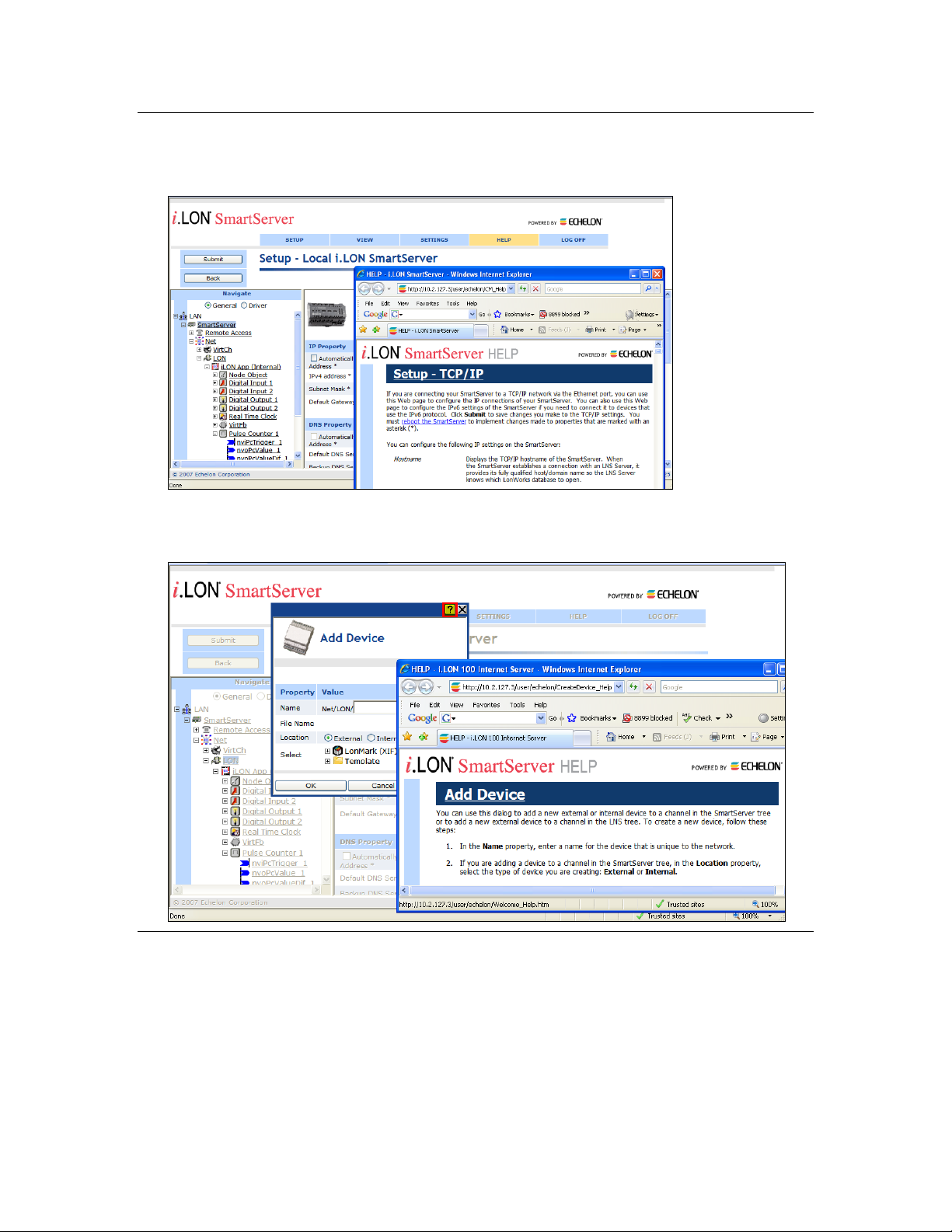
Using the SmartServer Help Files
If you need more information on how to use a particular SmartServer Web page, you can click Help to
open a new window with context-sensitive help for that Web page.
If you need help with a particular dialog in the SmartServer Web interface, you can click the “?” icon
in the upper-right hand corner of the dialog to open a new window with context-sensitive help for that
dialog.
Viewing the SmartServer 2.2 ReadMe
The SmartServer 2.2 ReadMe provides descriptions of known problems, if any, and their workarounds.
To view the SmartServer 2.2 ReadMe, click Start, point to Programs, point to Echelon SmartServer
2.2 Software, and then select SmartServer 2.2 ReadMe First. You can also find additional
information about the SmartServer online at www.echelon.com/ilon.
xvi Preface
Page 16

Using Technical Support
Region
Languages Supported
Contact Information
The Americas
English
Japanese
Echelon Corporation
Attn. Customer Support
550 Meridian Avenue
San Jose, CA 95126
Phone (toll-free):
1.800-258-4LON (258-4566)
Phone: +1.408-938-5200
Fax: +1.408-790-3801
lonsupport@echelon.com
Europe
English
German
French
Italian
Echelon Europe Ltd.
Suite 12
Building 6
Croxley Green Business Park
Hatters Lane
Watford
Hertfordshire WD18 8YH
United Kingdom
Phone: +44 (0)1923 430200
Fax: +44 (0)1923 430300
lonsupport@echelon.co.uk
Japan
Japanese
Echelon Japan
Holland Hills Mori Tower, 18F
5-11.2 Toranomon, Minato-ku
Tokyo 105-0001
Japan
Phone: +81.3-5733-3320
Fax: +81.3-5733-3321
lonsupport@echelon.co.jp
China
Chinese
English
Echelon Greater China
Rm. 1007-1008, IBM Tower
Pacific Century Place
2A Gong Ti Bei Lu
Chaoyang District
Beijing 100027, China
Phone: +86-10-6539-3750
Fax: +86-10-6539-3754
lonsupport@echelon.com.cn
If you have technical questions that are not answered by this document, the SmartServer 2.2 online
help, or the SmartServer 2.2 ReadMe document, you can contact technical support. Free e-mail
support is available or you can purchase phone support from Echelon or an Echelon support partner.
See www.echelon.com/support for more information on Echelon support and training services.
You can also view free online training or enroll in training classes at Echelon or an Echelon training
center to learn more about developing devices. You can find additional information about device
development training at www.echelon.com/training.
You can obtain technical support via phone, fax, or e-mail from your closest Echelon support center.
The contact information is as follows (check www.echelon.com/support for updates to this
information):
SmartServer User’s Guide xvii
Page 17

Region
Languages Supported
Contact Information
Other Regions
English
Japanese
Phone: +1.408-938-5200
Fax: +1.408-328-3801
lonsupport@echelon.com
xviii Preface
Page 18

1
Introduction
This chapter introduces the SmartServer, summarizes the new features
in the release of the SmartServer 2.2 software, and describes the
SmartServer built-in applications.
SmartServer 2.2 User’s Guide 19
Page 19

Introduction
The SmartServer 2.2 is a low-cost, high-performance, controller, network manager, router, network
interface, and Web server that connects LONWORKS, BACnet, M-Bus, and Modbus devices to
corporate IP networks or the Internet. It features a built-in Web server that allows Web access to all
the data managed and controlled by the SmartServer.
The SmartServer includes built-in applications for alarming, scheduling, logging, translating, and
performing arithmetic, logical and statistical functions on data types. It also includes a Web binder for
bridging multiple LONWORKS domains. The SmartServer also includes built-in I/O for reading pulse
meters and digital inputs, and for switching local loads. All data points and built-in I/O are accessible
through either the LONWORKS or Web interfaces.
The SmartServer can be used with the included Echelon Enterprise Services 2.2 (EES 2.2) for rapidly
deploying and managing SmartServers and integrating the SmartServer with OpenLNS CT and other
OpenLNS network tools.
EES 2.2 includes the i.LON AdminServer, which is a Web application that you can use to upgrade
SmartServers, backup and restore SmartServers, and create and deploy i.LON templates. For
example, you can backup or upgrade multiple SmartServers at the same time, or you can create a
template of one SmartServer and deploy that template on multiple SmartServers simultaneously. In
addition, when you deploy a template, you can have the SmartServer automatically or
semi-automatically install the devices in the SmartServer or OpenLNS network database included in
the template. This automatic network installation feature is supported for single-channel networks
containing up to approximately 20 devices.
EES 2.2 also includes the LNS Proxy Web service, which enables the SmartServer to directly
communicate with OpenLNS network databases on OpenLNS Server computers. This means that you
can use the SmartServer Web interface as a standalone OpenLNS network management tool to design,
install, monitor/control, and maintain LONWORKS networks, or you can synchronize the SmartServer
with an OpenLNS network database and use the SmartServer to monitor and control the network.
The SmartServer can also be used as a standalone network manager without a connection to an
OpenLNS Server. You can use the SmartServer in standalone mode to manage a small, single-channel
TP/FT-10 or PL-20 network that does not require OpenLNS management or LONWORKS connections.
In standalone mode, the SmartServer serves as a network manager that can directly load, commission,
set online/offline, wink, test, and reset the devices attached to its channel without sending the network
management commands through OpenLNS.
The SmartServer can be used as a Remote Network Interface (RNI), allowing you to use an OpenLNS
or OpenLDV based application, such as OpenLNS CT, to access to a single LONWORKS network
remotely. The SmartServer includes optional IP-852 routing, which you can use to access multiple
LONWORKS networks remotely (you can order IP-852 routing for new SmartServer units or activate it
later). The SmartServer can also be used with the LonScanner™ Protocol Analyzer to capture, analyze,
characterize, and display ISO/IEC 14908-1 Control Network Protocol (CNP) packets either locally or
remotely via the Internet.
The SmartServer includes an optional programming feature that you can use to create and run custom
built-in applications and drivers on the SmartServer called Freely Programmable Modules (FPMs).
The SmartServer also provides a SOAP/XML Web services interface for integration with custom
enterprise applications.
The SmartServer operates on 100 – 240 VAC high-voltage models that are available for TP/FT-10 and
PL-20 channels. An optional built-in 56K V.90 analog modem can be ordered with the TP/FT-10
models.
20 Introduction
Page 20

What’s New in the SmartServer 2.2 Software
The SmartServer 2.2 software includes the following new features:
LONWORKS Connections in Standalone Mode. Create peer-to-peer bindings in standalone
networks with repeating for rapid response to external events.
Increased Device and Data Point Limits in Standalone Mode. Install up to 300 devices and use up
to 2,000 data points in a standalone network.
Maintenance Network Management Mode. Rapidly commission networks by disabling data point
heartbeats and polling messages.
Static Repeating Mode. Optimize the performance of power line repeating channels by disabling
the periodic verification of repeating paths.
Enhanced XMPP Client. Use real-time bi-directional communication between SmartServers and
enterprise applications located behind firewalls. The SmartServer’s built-in XMPP client now
supports connections where the IP address changes because of lease timeouts, and it is now
compatible with Openfire.
OpenLNS Server and OpenLNS CT Support. Integrate the SmartServer in networks managed
with an OpenLNS Server. Use the SmartServer with networks managed with the OpenLNS
Commissioning Tool (OpenLNS CT).
i.LON Vision 2.2. Rapidly create custom SmartServer Web pages with the i.LON Vision 2.2
standalone Web publishing tool.
Cross Browser Support. View SmartServer 2.2 built-in and custom Web pages using Chrome and
Safari in addition to previously supported browsers (Internet Explorer and Firefox).
New Languages. View SmartServer 2.2 built-in and custom Web pages in Chinese, Korean, and
Japanese in addition to previously supported languages (English, French, and German).
Note: To use the new SmartServer 2.2 features on a SmartServer 1.0 (a SmartServer currently running
the Release 4, 4.01, or 4.02 firmware) or on an i.LON e3 plus Server, you must have a SmartServer 2.0
license for each SmartServer 1.0 to be upgraded to a SmartServer 2.2 (a SmartServer running the
Release 4.06 firmware).
LONWORKS Connections in Standalone Mode
You can create LONWORKS connections in standalone networks. This enables devices on a power line
repeating networks to send and receive event-driven updates. Previously, if you selected the
Standalone network management you could only bind devices using Web connections, which use
polling to transmit and receive data. For example, a presence sensor in a street lighting network can
now detect a car and send the event to an outdoor lighting controller (OLC) to illuminate a street light
and transmit the event to street lights further down the network.
For more information on creating LONWORKS connections in a standalone network, see Connecting
LonWorks Data Points with LonWorks Connections in Chapter 5.
For more information on using LONWORKS connection in a power line repeating network, see the
Power Line Repeating Network Management Guide.
Increased Device and Data Point Limits
You can now install up to 300 devices and use up to 2,000 data points in a standalone network. The
previous limit for standalone networks was 200 devices and 1,000 data points.
SmartServer 2.2 User’s Guide 21
Page 21

Maintenance Network Management Mode
You can speed up network commissioning using the new maintenance network management mode.
The Network Management Mode box in the Setup - LON Network Driver Web page includes a
new Maintenance option. When this option is selected, the SmartServer does not send out heartbeat
and polling messages. This increases the available bandwidth by freeing up the consumption from
checking data point heartbeats, sending poll requests, and receiving poll message responses. This
management mode is ideal for power line repeating networks. See the Power Line Repeating Network
Management Guide for more information.
Static Repeating Mode
You can optimize the performance of power line repeating networks using the new static proxy chains.
The Repeating box in the Setup - LON Channel Driver Web page includes a new On (Static Proxy
Chains) option. When this option is selected, the power line channel uses repeating, but the
SmartServer does not continuously try to discover and optimize the repeating chains used to
communicate messages from the SmartServer to the devices on the network. This increases the
available bandwidth on the power line repeating network for operational traffic. See the Power Line
Repeating Network Management Guide for more information.
Enhanced XMPP Client
You can use the Extensible Messaging and Presence Protocol (XMPP) to enable bi-directional
communication between SmartServers and enterprise applications located behind firewalls. For
SmartServer 2.2, the SmartServer XMPP client supports connections where the source or destination
IP address changes because of an IP lease timeout. In addition, the SmartServer XMPP client has new
configuration options that make it compatible with the Openfire XMPP server. For more information
on using the SmartServer XMPP client, see the SmartServer 2.2 XMPP Client Developer’s Guide.
OpenLNS Server and OpenLNS CT Support
SmartServer 2.2 supports the new OpenLNS Server when running in LNS mode. This enables the
SmartServer to remain synchronized with an OpenLNS database in a system managed with an
OpenLNS Server (for example, lighting systems and other building applications where an OpenLNS
Server is used to manage the network configuration). SmartServer 2.2 is compatible with the
OpenLNS Commissioning Tool and other OpenLNS tools.
i.LON Vision 2.2
You can rapidly create custom SmartServer 2.2 Web pages with the i.LON Vision 2.2 standalone Web
publishing tool.
With i.LON Vision 2.2, you can create custom Web pages for monitoring and controlling the data
points on your SmartServer 2.2—without any knowledge of HTML, JavaScript, or Web programming.
The i.LON Vision 2.2 toolkit provides many objects that you can use to read and write values to data
points, including basic read/write objects; SVG objects (for example, sliders, gauges, and
thermometers); application objects that expose some of the SmartServer’s built-in applications to your
end users; and a custom JavaScript object for implementing your own custom objects.
i.LON Vision 2.2 features quick Web page creation as you can switch between the edit and publish
views of your Web pages without long delays. This means that you can create or edit a custom Web
page and instantly see the results when you publish it.
Cross Browser Support
You can view the SmartServer 2.2 built-in and custom Web pages using Chrome and Safari in addition
to previously supported browsers (Internet Explorer and Firefox).
22 Introduction
Page 22

New Languages
You can view the SmartServer 2.2 built-in and custom Web pages in Chinese, Korean, and Japanese in
addition to previously supported languages (English, French, and German).
You can work with the SmartServer in any one-byte or two-byte character language by translating the
.properties file in the /web/nls/echelon folder on the SmartServer flash disk. You can perform this
language localization using either the demo version of the SmartServer 2.0 Programming Tools
included on the SmartServer 2.2 DVD or using the full version on the SmartServer 2.0 Programming
Tools included on the SmartServer 2.0 Programming Tools DVD. For more information on ordering
the SmartServer 2.0 Programming Tools DVD, contact your Echelon sales representative. See the
SmartServer 2.0 Programming Tools User’s Guide for more information on how to localize the
language of the SmartServer Web interface.
SmartServer Limits
The SmartServer 2.2 has the following limits:
Up to 4,096 address table entries.
Up to 32 simultaneous outgoing transactions.
Up to 1,024 network variable aliases.
The number of devices and data points supported by the SmartServer in OpenLNS managed
networks depends on the available memory on the flash disk.
The SmartServer can support up to 300 devices and 2,000 data points in standalone networks. This
limit may be lower depending on the number of data points and custom apps on the SmartServer.
The SmartServer’s App device can support up to 3,000 dynamic network variables, but the
SmartServer may run out of memory before this limit is reached. The practical limit depends on
the sizes of the defined dynamic network variables. You can check the available memory on your
SmartServer using the Setup - System Info Web page. To access this Web page, right-click the
SmartServer icon in the navigation pane in the left frame, point to Setup, and then click System
Info in the shortcut menu. Alternatively, you can click Setup and then click System Info.
SmartServer Compatibility with Network Management Services and Tools
You can integrate the SmartServer 2.2 in systems managed by OpenLNS and LNS Turbo Edition
Servers (version 3.25 or newer). In addition, the SmartServer 2.2 is compatible with the OpenLNS
Commissioning Tool (CT), other OpenLNS tools, the LonMaker tool, and other LNS tools. For
simplicity when describing network management services and Echelon network tools hereafter, this
document references only OpenLNS Server and OpenLNS CT. For more information on integrating
the SmartServer 2.2 with OpenLNS CT, see Chapter 12, Using the SmartServer with OpenLNS CT.
SmartServer 2.2 User’s Guide 23
Page 23

24 Introduction
Page 24

2
Installing the SmartServer 2.2 Products
This chapter describes how to install the Echelon SmartServer 2.2
products including the SmartServer 2.2 software, SmartServer 2.0
Programming Tools Demo, Echelon Enterprise Services 2.2, i.LON
Vision 2.2, and Echelon NodeBuilder Resource Editor 4.02.
SmartServer 2.2 User’s Guide 25
Page 25
Installation Overview
The following sections describe how to install the following SmartServer products:
Echelon SmartServer 2.2 software.
Echelon i.LON Enterprise Services 2.2.
Echelon i.LON Vision 2.2 Software.
Echelon NodeBuilder Resource Editor 4.02.
Installing Echelon SmartServer Software
To install the SmartServer 2.2 software, follow these steps:
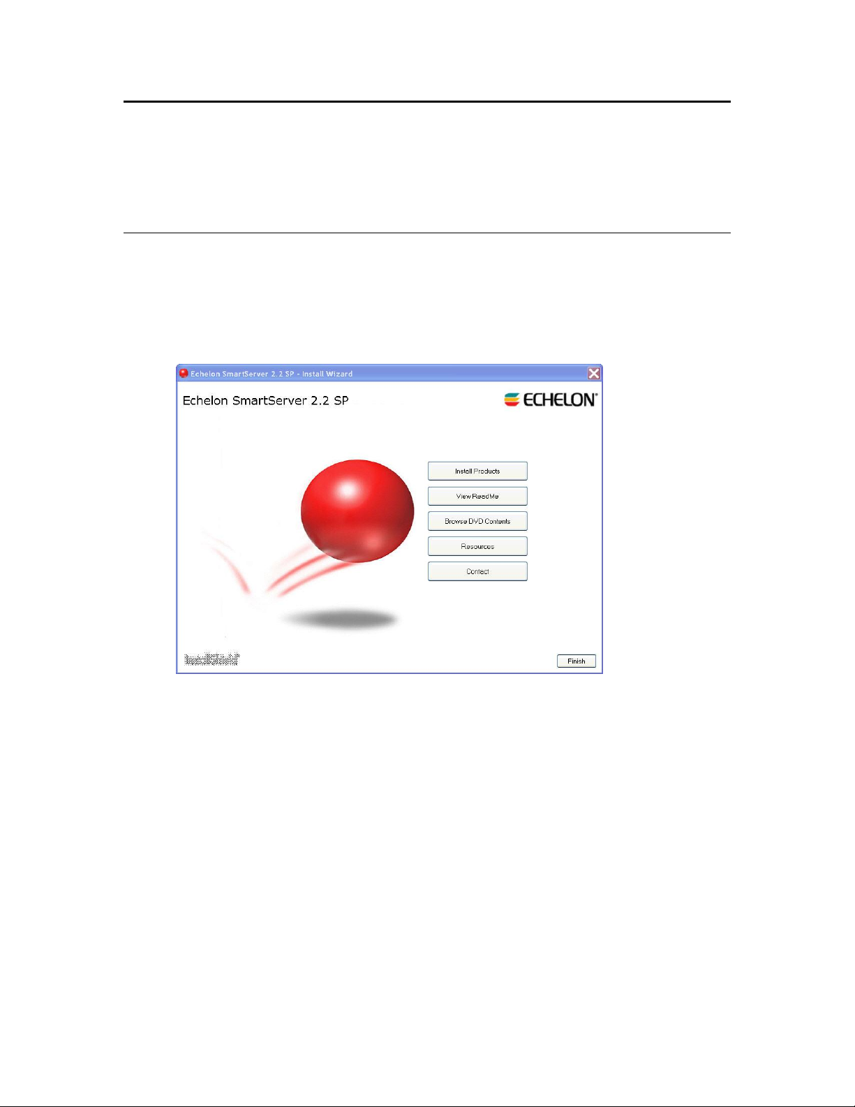
1. Download the SmartServer 2.0 SP4 (SmartServer 2.2) to your computer and click on the
downloaded executable(153-0547-01a_SmartServer_2_SP4_downloader.exe). A WinZip SelfExtractor will pop up and if you click the Unzip button, it will unzip and automatically open the
Echelon SmartServer 2.2 SP main menu.
2. Click Install Products. The Install Products dialog opens.
26 Installing the SmartServer Products
Page 26
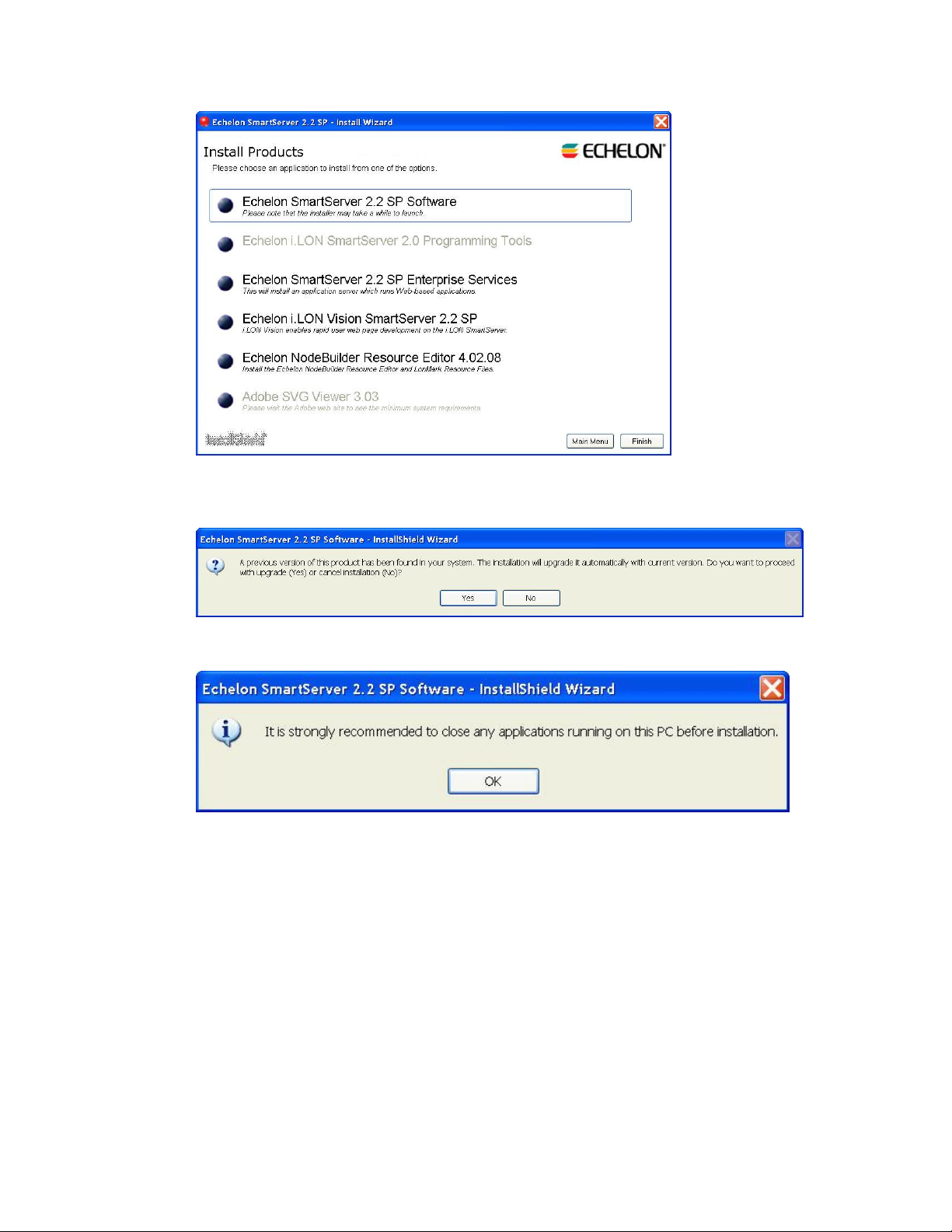
3. Click Echelon SmartServer 2.2 SP Software. If SmartServer 1.0 software (Release 4.0, 4.01, or
4.02) is installed on your computer, the following dialog opens prompting you to confirm that you
want to upgrade to the SmartServer 2.2 software. Click Yes to upgrade.
4. A dialog opens prompting to close all applications currently running on your computer. Close any
applications running on your computer, and then click OK.
5. The Welcome window of the SmartServer 2.2 SP software installer opens. The original product
name was i.LON SmartServer, so i.LON may appear on some of the screens.
SmartServer 2.2 User’s Guide 27
Page 27
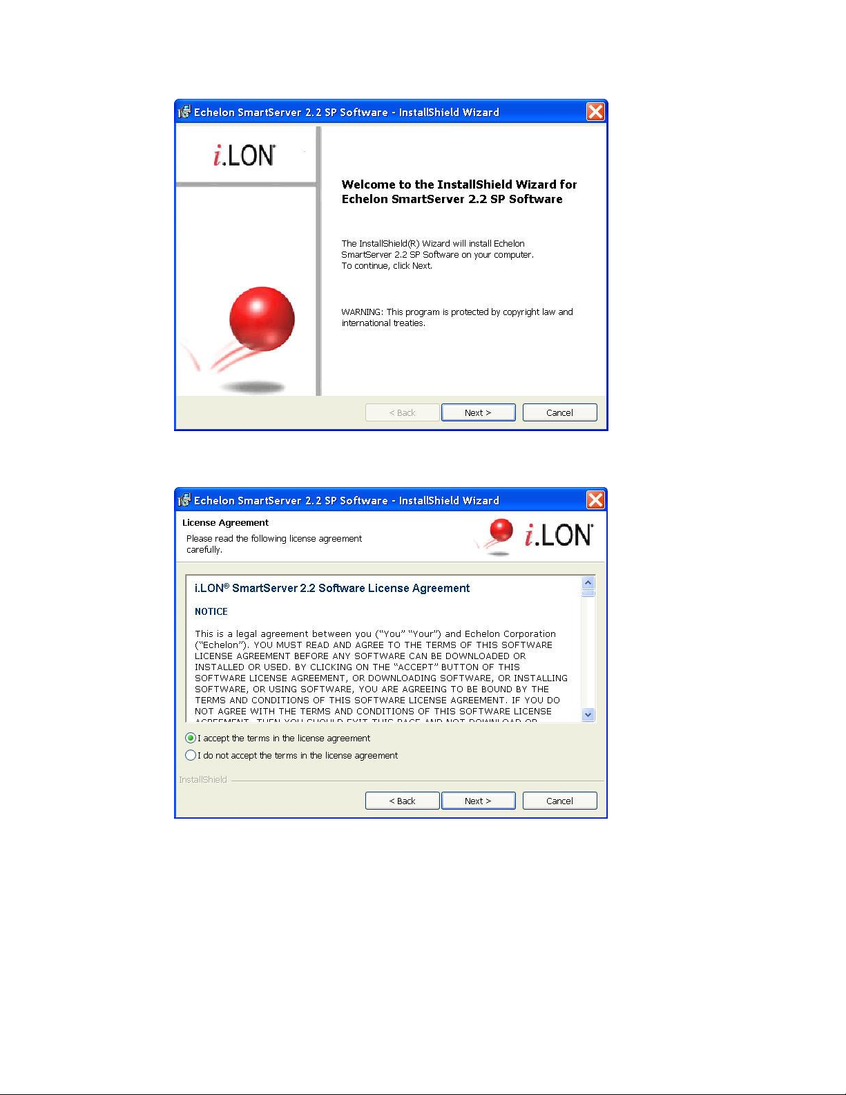
6. Read the information on the Welcome window and click Next.
7. The License Agreement window appears.
8. Read the license agreement (you can read a printed version of the license agreement in Appendix
E, Software License Agreements). If you agree with the terms, click Accept the Terms and then
click Next. The Customer Information window appears.
28 Installing the SmartServer Products
Page 28
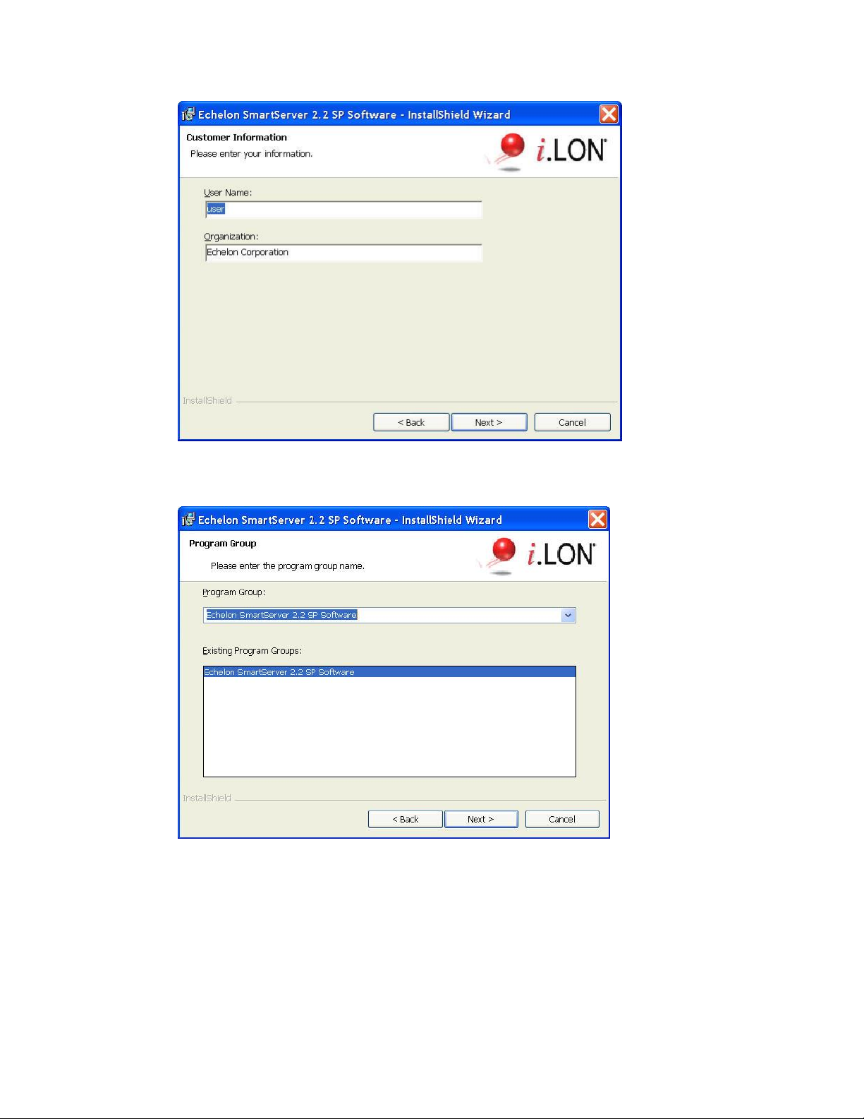
9. Enter your name and company name in the appropriate fields. The name and company may be
entered automatically based on the user currently logged on and whether other Echelon products
are installed on your computer. Click Next. The Program Group window appears.
10. Enter or select a program group in the Start menu to use for starting the SmartServer applications
and accessing the SmartServer images and documentation. The default program group is Echelon
SmartServer 2.2 SP Software. By default, the SmartServer 2.2 SP software, SmartServer 2.2 SP
image (iLon100 4.06), and documentation will be installed in the LonWorks\iLon100 LonWorks
folder. The Setup Type window appears.
SmartServer 2.2 User’s Guide 29
Page 29
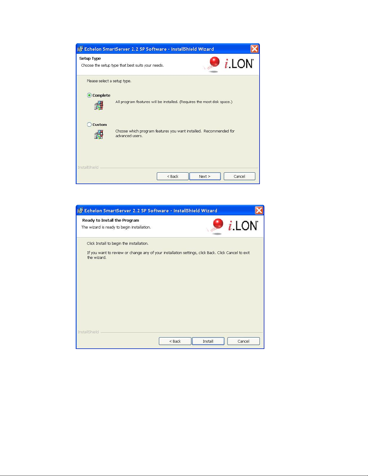
11. Select the type of installation to be performed. It is recommended that you select Complete.
Click Next. The Ready to Install window appears.
12. Click Install to begin the SmartServer software installation. The installer first checks whether
OpenLDV 4.0 is installed on your computer. If OpenLDV 4.0 is not installed on your computer,
the SmartServer 2.2 SP software installer will automatically install it before installing the
SmartServer 2.2 software.
13. After the SmartServer 2.2 SP software has been installed, a window appears stating that the
installation has been completed successfully. The window also provides you with an option to
view the SmartServer 2.2 SP ReadMe, which contains information that is not included in this
user’s guide, and an option to view the default IPv6 link local address of your SmartServer.
30 Installing the SmartServer Products
Page 30
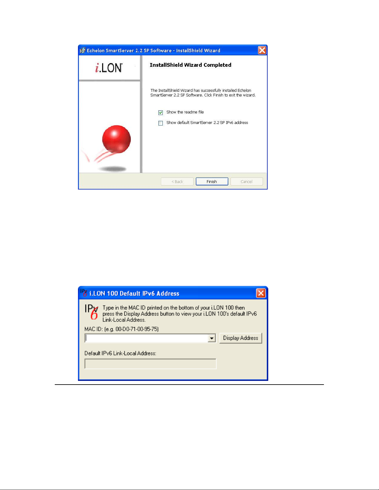
14. Click Finish. If you need to reboot your computer, a window will appear prompting you to select
to reboot your computer now or later.
15. The SmartServer 2.2 ReadMe file appears. When you finish reading the SmartServer 2.2 ReadMe,
close the window.
16. If you chose to display the default IPv6 link local address (you can open this dialog by clicking
Start, pointing to Programs, pointing to Echelon SmartServer 2.2 Software, and then clicking
SmartServer 2.2 Default IPv6 Address.), enter the MAC ID address of your SmartServer in the
MAC ID box (the MAC ID is located on the bottom of your SmartServer hardware device), and
then click Display Address to show the default IPv6 address.
17. To use this IPv6 address to access your SmartServer you need to enable IPv6 on your SmartServer
as described in Configuring TCP/IP Properties in Chapter 3.
Installing Echelon SmartServer 2.2 Enterprise Services
The Echelon Enterprise Services 2.2 (EES 2.2) includes the i.LON Admin Server used for managing
and deploying SmartServers, and the LNS Proxy Web service and Tomcat 6 Server used for
communication between the SmartServer and OpenLNS or LNS network databases. You need to
install EES 2.2 in order to synchronize the SmartServer to an OpenLNS or LNS network database, and
add the data points of external devices in OpenLNS or LNS managed networks to the SmartServer’s
built-in applications.
SmartServer 2.2 User’s Guide 31
Page 31

If you are using LNS mode, or if you are using EES to convert binary log files to CSV format, you
must install either an OpenLNS Server or an LNS Server. The OpenLNS Server is included with the
OpenLNS Commissioning Tool and other OpenLNS tools. The LNS Server is included with the
LonMaker Integration Tool and other LNS tools. If you do not have either server, you can download
the OpenLNS Server from www.echelon.com/openlns.
To install the Echelon i.LON Enterprise Services, click the Echelon SmartServer 2.2 SP – Install
Wizard button in the taskbar to return to the SmartServer 2.2 installer, click Echelon SmartServer 2.2
SP Enterprise Services in the Install Products dialog, and then follow the on-screen instructions.
See the Echelon Enterprise Services 2.2 User’s Guide for more information on installing the EES 2.2
software.
After the Echelon Enterprise Services has been installed, the Tomcat 6 Server starts and an EES tray
tool ( ) is added to the notification area of your desktop. If you have installed an OpenLNS Server or
LNS Server, the LNS Proxy Web service is enabled and ready for setup on your SmartServer. For
instructions on setting up and troubleshooting the LNS Proxy Web service, see Adding an OpenLNS
Server to the LAN section in Chapter 3, Configuring and Managing the SmartServer.
For more information on using the i.LON Admin Server and using the EES tray tool, see the Echelon
Enterprise Services 2.2 User’s Guide.
Installing Echelon i.LON Vision Software
You can install the i.LON Vision 2.2 software to create custom 2.2 SmartServer Web pages for
monitoring and controlling your networks.
To install the i.LON Vision 2.2 software, click the Echelon SmartServer 2.2 SP – Install Wizard button
in the taskbar to return to the SmartServer 2.2 installer, click Echelon i.LON Vision SmartServer 2.2
SP in the Install Products dialog, and then follow the on-screen instructions. See the i.LON Vision
2.2 User’s Guide for more information on installing this software.
Installing Echelon NodeBuilder Resource Editor
You can install Echelon NodeBuilder Resource Editor 4.02 and LonMark Resource Files 14 to view,
create, and modify device resource files.
To use the new fast data log transfer feature, the device resource files for the subject data points must
be installed on your computer running EES 2.2. You must also install an OpenLNS Server or LNS
Server to use the new fast data log transfer feature. If you installed an OpenLNS Server, you already
have the version 14 Standard Resource File Set. You can manually copy any user-defined device
resource files to the LonWorks\types\user\<company> folder to your EES 2.2 computer. If you send
binary data logs from your SmartServer to be converted to CSV format and the device resource files
for the subject data points are not present, the conversion will fail.
To install the Echelon NodeBuilder Resource Editor, follow these steps:
1. Click the Echelon SmartServer 2.2 SP – Install Wizard button in the taskbar to return to the
SmartServer 2.2 installer, click Echelon NodeBuilder Resource Editor in the Install Products
dialog.
2. The Welcome window of the NodeBuilder Resource Editor installer opens.
32 Installing the SmartServer Products
Page 32

3. Read the information on the Welcome window and click Next. The License Agreement window
appears.
4. Read the license agreement. If you agree with the terms, click Accept the Terms and then click
Next. The Customer Information window appears.
SmartServer 2.2 User’s Guide 33
Page 33

5. Enter your name, company name, phone number, e-mail address, and company Web site address
in the appropriate fields. Optionally, you can enter your company’s 5-digit manufacturer ID in
hexadecimal format in the Manufacturer ID box (if you do not have a manufacturer ID, you can
get a temporary manufacturer ID from LonMark at www.lonmark.org/mid). You can enter this
information so that it can automatically be entered when you create resource files with the
NodeBuilder Resource Editor. Click Next. The Ready to Install window appears.
6. Click Install to begin the NodeBuilder Resource Editor installation. After the NodeBuilder
Resource Editor has been installed, a window appears stating that the installation has been
completed successfully.
34 Installing the SmartServer Products
Page 34

7. Click Finish.
8. If you installed the NodeBuilder Resource Editor on a computer that has not had any other
Echelon software previously installed on it, you need to register the Echelon resource files in the
resource catalog. To do this, follow these steps:
a. Start the NodeBuilder Resource Editor. To do this, click Start, point to Programs, point to
Echelon NodeBuilder Resources, and then click NodeBuilder Resource Editor. The
Echelon NodeBuilder Resource Editor opens
b. Click File, and then select Add Folder.
c. Browse to the C:\Lonworks\types\user\echelon directory, and then click OK.
d. Click File, and then select Refresh Catalog.
Installing a BACnet Interface
You can purchase and install a BACnet interface for the SmartServer. The BACnet interface is a
custom app for the SmartServer provided by ConnectEx, Inc. It provides an interface that is
compatible with all common BACnet AWS/OWS workstations. For more information on the BACnet
interface for the SmartServer, contact ConnectEx.
SmartServer 2.2 User’s Guide 35
Page 35

36 Installing the SmartServer Products
Page 36

3
Configuring and Managing the
SmartServer
This chapter describes how to connect your SmartServer to a TCP/IP network. It
describes how to use the Setup Web pages to configure the SmartServer’s properties.
It explains how to add dial-up connections to your SmartServer if an Ethernet
connection is not readily available. It explains how to connect host devices such as
remote SmartServers, OpenLNS Servers, e-mail servers, time servers, IP-852
Configuration Servers, and Web Connection Target servers to your local
SmartServer. It describes how to configure your SmartServer as an IP-852 router and
as a remote network interface (RNI). It describes how to manage your SmartServer,
including how to view its performance; view its system health monitoring
configuration, test its connections; replace it; activate the V40 interface on it; and
migrate an i.LON 100 e3 server network configuration to a SmartServer.
SmartServer 2.2 User’s Guide 37
Page 37

SmartServer Configuration and Management Overview
You can connect and configure your SmartServer before using it to manage, monitor, and control your
networks. To connect the SmartServer you assemble, mount, and wire the SmartServer as described in
the SmartServer Hardware Guide, use an Ethernet cable to connect it to a TCP/IP network, and then
open the SmartServer Web interface.
After you connect your SmartServer, you can use the SmartServer’s Setup Web pages to set its IP
address, SOAP/HTTP services, real-time clock, and security settings. After you configure the security
settings, you can disable the Setup - Security Web page so that other users cannot modify the security
settings. If you change TCP/IP properties marked with an asterisk (*) or security properties marked
with a double-asterisk (**) you need to reboot your SmartServer to implement the changes.
You can create dial-up connections for your SmartServer if an Ethernet connection is not readily
available. You can use the built-in analog modem on the SmartServer (certain hardware models only)
or connect the SmartServer to an external GSM modem. If you create a dial-out connection, you can
connect your SmartServer to other host devices via that connection.
You can connect a number of host devices to your SmartServer by adding them to the SmartServer’s
LAN or dial-up connections. You can add remote SmartServers, OpenLNS Servers, time (SNTP)
servers, e-mail (SMTP) servers, IP-852 Configuration Servers (if you are not using the standard port
on the SmartServer for IP-852 routing [1628]), and Web Connection Target servers (Web server that
can receive SOAP/HTTP requests).
Adding a remote SmartServer lets you connect the devices on your SmartServer to the devices on
that remote SmartServer, and it lets you manage that remote SmartServer and the network attached
to it from the Web interface of your local SmartServer.
An OpenLNS Server lets you use the LNS Proxy Web service to synchronize the SmartServer to
an OpenLNS network database; add the data points of external devices in OpenLNS managed
networks to the SmartServer’s built-in applications and your custom SmartServer Web pages; and
maintain and manage the OpenLNS network databases in an OpenLNS Server.
An e-mail server lets the SmartServer send out e-mail notifications when alarm conditions occur.
A time server lets you synchronize the date and time on the SmartServer and the other host
devices on the LAN to a common base.
An IP -852 Configuration Server lets you create and manage IP-852 channels.
A Web Connection Target server lets you send data logs, alarm logs, an event scheduler log, or
any user-defined file from your SmartServer to a central enterprise system.
After you configure your SmartServer, you can select a network management service mode. You can
run your SmartServer with OpenLNS network management services or you can use the SmartServer as
a standalone network manager.
In LNS mode (LNS Auto or LNS Manual), the SmartServer uses an OpenLNS Server or LNS
Server to manage the network. You must use LNS mode if your network is managed by an
OpenLNS Server or an LNS Server. Using LNS mode requires you to install the Echelon
Enterprise Services 2.2 from the SmartServer 2.2 DVD, install an OpenLNS or LNS Server, and
then add an LNS Server to the LAN.
In Standalone mode, the SmartServer directly manages the network. You must use standalone
mode if an OpenLNS Server or LNS Server is not available for your network. You can use
standalone mode to install and operate a small, single-channel network that does not require
OpenLNS services or connections to other network management tools. Networks running in
standalone mode are limited to a maximum of 300 devices (for FT-10 networks, you need to
attach a physical layer repeater to the network to exceed the 64-device limit posed by the physical
channel).
38 Configuring and Managing the SmartServer
Page 38

You can configure your SmartServer as an IP-852 router (if IP-852 routing is activated on your
SmartServer) to integrate the network attached to your SmartServer into a single large LONWORKS
network that runs over a high-speed IP backbone. You can also configure your SmartServer as an
IP-852 router or as a remote network interface (RNI) to connect an OpenLNS or OpenLDV-based
application to a LONWORKS network remotely via a TCP/IP connection.
You can manage your SmartServer by viewing its performance with the Setup – System Info Web
page; viewing the configuration of its system health monitoring with the systemhealth.conf file on the
SmartServer flash disk; testing its connections with the Setup – Verify Web page; backing it up to
protect your network configuration and your custom SmartServer Web pages; upgrading the firmware
when service packs become available; restoring the SmartServer from a backup or restoring it to its
factory default settings with the SmartServer Web pages or the console application; replacing your
SmartServer if there is a hardware failure; and activating the V40 interface so that you can add
dynamic functional blocks to the i.LON App (Internal) device. You can also migrate an i.LON 100
e3 server network to the SmartServer.
This chapter describes how to perform the following tasks:
1. Connect the SmartServer.
2. Configure the SmartServer.
3. Create modem connections.
4. Add host devices to the LAN.
5. Select a network management service.
6. Configure the SmartServer as an IP-852 router or an RNI.
7. Manage the SmartServer.
Connecting the SmartServer
After you install the SmartServer software on your computer, you need to connect your SmartServer to
a TCP/IP network. To connect your SmartServer, follow these steps:
1. Assemble, mount, and wire the SmartServer as described in the SmartServer Hardware Guide.
Open the SmartServer Web pages using IPv4 or IPv6.
2. If you are using IPv4 to open the SmartServer Web pages, follow these steps:
a. If your computer is not on the same subnet as the SmartServer (192.168.1.x by default), open
a Windows command prompt with administrator privileges on your computer and enter the
following command:
route add 192.168.1.0 mask 255.255.255.0 %computername%
Note: To open the command prompt with administrator privileges, click Start, type cmd in
the search box, right-click the cmd.exe, and then select Run as Administrator. If you
receive a “The parameter is incorrect” error after entering the route command, replace
%computername% with the IP address of your computer.
b. Open a Web browser and enter the IP address of your SmartServer. The default address is
http://192.168.1.222.
3. If you are using IPv6 to open the SmartServer Web pages, follow these steps:
a. Enable the IPv6 interface on your computer. For more information on doing this on a
Windows 7 computer, see http://windows.microsoft.com/en-us/windows7/ipv6-frequently-
asked-questions.
b. Set up a DNS entry to create a hostname for the SmartServer. When setting up the DNS
entry, use the default IPv6 address shown by the installation wizard (see step 18 in Installing
Echelon SmartServer Software in Chapter 2)
c. Create the hostname for the SmartServer.
SmartServer 2.2 User’s Guide 39
Page 39

4. The SmartServer 2.2 home page opens.
5. In the Configuration & Service box, select the language to be used for the SmartServer Web
interface. The SmartServer includes English (the default), German, French, Chinese, Korean, and
Japanese languages, but you can work with the SmartServer in any one-byte or two-byte character
language by translating the .properties file in the /web/nls/echelon folder on the SmartServer flash
disk.
You can perform this language localization using either the demo version of the SmartServer 2.0
Programming Tools included on the SmartServer 2.2 DVD or using the full version on the
SmartServer 2.0 Programming Tools included on the SmartServer 2.0 Programming Tools DVD.
For more information on ordering the SmartServer 2.0 Programming Tools DVD, contact your
Echelon sales representative.
See the SmartServer 2.0 Programming Tools User’s Guide for more information on how to
localize the language of the SmartServer Web interface.
6. Click Login. A Login dialog opens.
40 Configuring and Managing the SmartServer
Page 40

7. Enter the User name and Password for logging on to your SmartServer, which are both ilon by
default, and then click OK. The SmartServer - Welcome Web page opens.
The navigation pane on the left side of the SmartServer Web pages provides a hierarchal view of the
LAN on which your local SmartServer resides. The top level of the navigation pane shows the LAN
icon, which represents the SmartServer’s Ethernet connection. The host devices on the LAN are then
listed one level below the LAN icon. When you initially connect your SmartServer, your local
SmartServer and a sample e-mail server are the only host devices on the LAN. The remote access
(modem) connections and the network attached to your local SmartServer are listed one level below
the local SmartServer icon.
You can connect other host devices to your local SmartServer via its Ethernet connection or a dial-up
modem connection. The host devices you can connect to your local SmartServer include OpenLNS
Servers, e-mail (SMTP) servers, time servers (SNTP), IP-852 Configuration Servers, Web Connection
Target servers, and remote SmartServers. See Adding Host Devices later in this chapter for more
information on how to do this.
SmartServer 2.2 User’s Guide 41
Page 41

Configuring the SmartServer
After you can connect your local SmartServer to a TCP/IP network, you can use the SmartServer’s
Setup Web pages to configure its TCP/IP, SOAP/HTTP, time, and security properties. When you
change the TCP/IP and security properties of the SmartServer, you may be required to reboot your
SmartServer. The following sections describe how to perform the following configuration tasks for a
SmartServer.
Configure TCP/IP properties.
Configure SOAP/HTTP properties.
Configure time properties.
Configure security properties.
Reboot the SmartServer.
Configuring TCP/IP Properties
If you are connecting your SmartServer directly to a TCP/IP network via the Ethernet port, you must
configure the SmartServer’s TCP/IP connection properties. To configure the TCP/IP properties,
follow these steps:
1. Right-click the SmartServer icon, point to Setup, and then click TCP/IP on the shortcut menu.
Alternatively, you can click Setup and then click TCP/IP to configure the TCP/IP properties on
your local SmartServer.
2. The Setup – Local SmartServer (TCP/IP) Web page opens.
42 Configuring and Managing the SmartServer
Page 42

Hostname
Displays the TCP/IP hostname of the SmartServer. When the SmartServer
establishes a connection with an OpenLNS Server, it provides its fully
qualified host/domain name so the OpenLNS Server knows which
LONWORKS database to open.
By default, the hostname is SmartServer. The URL of the SmartServer is
the hostname followed by the DNS suffix. For example, if the hostname
is SmartServerAlpha and the domain suffix is ABCcorp.com, the URL
would be SmartServerAlpha.ABCcorp.com.
Set a unique hostname if you want to have the DHCP server register the
hostname with the DNS server, or when you want to manually register
with the DNS server administrator.
The hostname must start with a letter and it may include numbers, letters,
and hyphens, but it cannot include underscores or spaces. The maximum
hostname length is 19 characters.
IP Property
If you modify any of the following IP properties, you must reboot your
SmartServer to implement the changes.
3. Configure the following IPv4 properties. You must reboot the SmartServer to implement changes
made to properties that are marked with an asterisk (*).
SmartServer 2.2 User’s Guide 43
Page 43

Automatically
Obtain IP Address
Enables the SmartServer to obtain its IP address, subnet mask, and default
gateway from the local network’s DHCP server. As soon as the DHCP
server is contacted, the SmartServer reboots and implements the new IP
address. If the DHCP server cannot be contacted, the IP address, subnet
mask, and gateway are temporarily set to the following addresses:
IP address: 192.168.1.222
Subnet mask: 255.255.255.0
Gateway: 192.168.1.222
Selecting this option makes the subsequent IPv4 Address, Subnet Mask,
and Default Gateway properties unavailable.
If you plan to use the SmartServer as an IP-852 router, you must ensure
that the SmartServer uses a fixed IP address. See the DHCP section in
Chapter 4 of the IP-852 Channel Users Guide for more information on
this issue.
IPv4 Address
Enter the static IPv4 address used by the SmartServer. Make sure that the
IP address you enter is not in a range reserved by a local DHCP server.
The default IPv4 address is 192.168.1.222.
Note: If you are using a modem connection, enter a static IP address that
is outside the range of the SmartServer’s Ethernet connection.
This property is unavailable if you select Automatically Obtain IP
Address.
Subnet Mask
Enter the subnet mask used by the SmartServer. The default subnet mask
is 255.255.255.0.
This property is unavailable if you select Automatically Obtain IP
Address.
Default Gateway
Enter the IP address of the gateway used by the SmartServer. The default
IP address is 192.168.1.222.
This property is unavailable if you select Automatically Obtain IP
Address.
DNS Property
If you modify any of the following DNS properties, you must reboot your
SmartServer to implement the changes.
Automatically
Obtain IP Address
Enables the SmartServer to obtain its DNS Server Address from the local
network’s DHCP server. If the DHCP server cannot be contacted, this
property is temporarily set to 0.0.0.0. As soon as the DHCP server is
contacted, the SmartServer will reboot itself to implement the new DNS
Server IP address.
Selecting this option makes the subsequent Default DNS Server and
Backup DNS Server properties unavailable.
Default DNS
Server
Enter the IP address of the primary DNS server used to resolve OpenLNS
Server names, DNS server names, hostnames, and so on. An IT
department typically provides this information. The default IP address of
the default DNS server is 0.0.0.0.
This property is unavailable if you select Automatically Obtain IP
Address.
Backup DNS
Server
Enter the IP address of the secondary DNS server used to resolve names.
The default IP address of the backup DNS server is 0.0.0.0.
44 Configuring and Managing the SmartServer
Page 44

This property is unavailable if you select Automatically Obtain IP
Address.
IPv6 Property
Enable IPv6
Interface
Enables the SmartServer to connect to devices and servers that use IPv6.
This option is selected by default.
Link Local
Address (auto
configured)
Displays the IPv6 link local address assigned to the SmartServer. The link
local address can only be accessed by IPv6 devices on the local network to
which the SmartServer is attached. If a router is present between your
computer and the SmartServer you will not be able to use this address to
communicate with the SmartServer. Both addresses are automatically
configured by the SmartServer when the IPv6 interface is enabled.
Note: To use this local IPv6 link local address, you need to append the
‘%’ character and the number of your computer’s network card to the IPv6
address. You can obtain this number by entering the ipconfig in the
Windows command prompt. The network interface is normally named
“Ethernet adapter Local Area Connection”, and the card number is the
number after the ‘%’ character in your computer’s IPv6 address.
For example, if your SmartServer’s IPv6 address is
FE80::2D0:71FF:FE03:0122 and your computer’s IPv6 address is
FE80::213:72FF:FE98:a649%5, enter the following in your Web browser
to access the SmartServer via IPv6:
http://FE80::2D0:71FF:FE03:0122%5
4. Select the Advanced check box to configure IPv6 properties. The IPv6 properties appear on the
Web page.
5. Configure the following IPv6 properties. You must reboot the SmartServer to implement changes
made to properties that are marked with an asterisk (*).
SmartServer 2.2 User’s Guide 45
Page 45

Global Address
(auto configured)
Displays the IPv6 global address assigned to the SmartServer. The global
address is accessible to IPv6 devices outside the local network to which
the SmartServer is attached.
Current Default
Gateway
Displays the default gateway used by SmartServer for IPv6 addressing.
Use Additional
Static Address
Enables you to manually assign the SmartServer an additional IPv6
address and gateway in the properties below, in addition to the default link
local address and global address displayed on the Web page. If you select
this option, you must reboot your SmartServer to implement any changes.
IPv6 Address
Enter an additional IPv6 address for the SmartServer to use. The
addresses must conform to IPv6 addressing standards or an error will
occur when you click Submit. The following provides two example IPv6
addresses:
2002:1234:0000:0000:02d0:71ff:fe00:00aa
2002:1234::2d0:71ff:fe00:aafe::fefe:dddd
The IPv6 Address field also supports an optional prefix length specifier,
which must be a “/” followed by a decimal integer between 0 and 128. If
it is omitted, it will default to 64. The following provides an IPv6 address
with the prefix length specifier 64:
2002:1234::2d0:71ff:fe00:aa/64
For more details on IPv6 addressing, see “RFC 3513 - Internet Protocol
Version 6 (IPv6) Addressing Architecture” online at:
http://www.faqs.org/rfcs/rfc3513.html. Section 2.2 of the RFC describes
the addressing formats shown above in more detail, and section 2.3 of the
RFC provides more details on prefix specifiers.
Default Gateway
Enter an additional IPv6 address for the SmartServer to use as a gateway.
IPv6 DNS Property
Automatically
Obtain IP Address
Enables the SmartServer to obtain its DNS Server IPv6 address from the
local network’s DHCP server. If the DHCP server cannot be contacted,
this property is temporarily set to 0.0.0.0. As soon as the DHCP server is
contacted, the SmartServer will reboot itself to take on the new DNS
Server IP address.
Selecting this option makes the subsequent Default DNS Server and
Backup DNS Server properties unavailable.
Default DNS Server
Enter the IPv6 address of the primary DNS server used to resolve
OpenLNS Server names, DNS server names, hostnames, and so on. An IT
department typically provides this information.
This property is unavailable if you select Automatically Obtain IP
Address.
Backup DNS Server
Enter the IPv6 address of the secondary DNS server used to resolve
names.
This property is unavailable if you select Automatically Obtain IP
Address.
46 Configuring and Managing the SmartServer
Page 46

TCP/IP Property
Ethernet Media
Speed
You can select the Ethernet speed (10 or 100 MB per second) and mode
(full-duplex or half-duplex) of the SmartServer. You have five choices:
Automatic. The SmartServer employs autonegotiation to determine
the Ethernet speed and mode to use based upon the device with which
it is communicating. This is the default.
100 MB Full-Duplex. Data streams in both directions
simultaneously at 100 MB/s.
100 MB Half-Duplex. Data streams in one direction at a time at 100
MB/s
10 MB Full-Duplex. Data streams in both directions simultaneously
at 10 MB/s.
10 MB Half-Duplex. Data streams in one direction at a time at 10
MB/s
6. Click Submit to save the changes. If you change the IP address and want to continue to have Web
access to your SmartServer you must change your computer’s TCP/IP settings to place it on the
same subnet as the SmartServer.
7. If you modified a property marked with an asterisk (*), you must reboot your SmartServer. See
the Rebooting the SmartServer section later in this chapter for more information on how to do this.
Configuring SOAP/HTTP Service Properties
You can configure your SmartServer’s SOAP/HTTP service properties, following these steps:
1. Right-click the SmartServer icon, point to Setup, and then click Service on the shortcut menu.
Alternatively, you can click Setup and then click Service to configure the SOAP/HTTP properties
on your local SmartServer.
2. The Setup – Local SmartServer (Service) Web page opens.
SmartServer 2.2 User’s Guide 47
Page 47

Hostname
Displays the TCP/IP hostname of the SmartServer. When the SmartServer
establishes a connection with an OpenLNS Server, it provides its fully
qualified host/domain name so the OpenLNS Server knows which
LONWORKS database to open.
By default, the SmartServer’s hostname is SmartServer. The URL of the
SmartServer is the hostname followed by the DNS suffix. For example, if
the hostname is SmartServerAlpha and the domain suffix is
ABCcorp.com, the URL would be SmartServerAlpha.ABCcorp.com.
Set a unique hostname if you want to have the DHCP server register the
hostname with the DNS server, or when you want to manually register
with the DNS server administrator.
The hostname must start with a letter and it may include numbers, letters,
hyphens, and underscores, but it cannot include spaces. The maximum
hostname length is 19 characters.
SmartServer
Property
Logical ID
Displays the user-specified identifier used to manage the SmartServer. By
default, the logical ID is set to the Neuron ID of the SmartServer’s i.LON
App device. You can change the logical ID to any value containing one
or more 2-digit hex pairs (00-FF). For example, 00, 00FF, and 00FF00 are
legal logical IDs.
SOAP Path
The path on the SmartServer to which SOAP messages should be
transmitted. This is typically the location of the WSDL or ASMX file on
the server where it receives SOAP messages. The default path is
/WSDL/iLON100.WSDL (the default location of this file on a
SmartServer).
You can password protect the SmartServer’s WSDL using the i.LON
Web Server Security and Parameters program, or by manually
3. Configure the following SOAP/HTTP service properties.
48 Configuring and Managing the SmartServer
Page 48

configuring the webparams.dat file located at the root level of the
SmartServer ‘s flash disk. See Appendix C for more information on
protecting the WSDL using the i.LON Web Server Security and
Parameters program.
HTTP Port (Web
Server/SOAP)
The port the your local SmartServer uses to serve HTTP requests (SOAP
and WebDAV). The default value is 80, but you may change it to any
valid port number. Contact your IS department to ensure your firewall is
configured to allow access to the server on this port.
Retry Time
Set the amount of time (in seconds) after which the local SmartServer will
not resend failed Web Connection connection messages to the Web
Connection destination. The default value is 120 seconds.
The local SmartServer automatically attempts to resend failed Web
Connection connection messages to the Web Connection destination every
45 seconds.
Format Values in
Web Connection
SOAP Messages
Using
Select the format used for communicating data point values to the Web
Connection destination. You have two choices:
Data Point Format. Data point values are transmitted in the format
defined by their SNVT, UNVT, SCPT, or UCPT.
Raw HEX. Data point values are transmitted in raw hex.
Maximum Age
Specify the maximum age (in seconds) to be written to the target data
points on the Web Connection destination when the local SmartServer
sends updated values to them.
If the Web Connection destination cannot communicate with the parent
device of the target data point, the Web Connection destination caches the
updated value it received from the local SmartServer. When the device
goes online, the cached value is written to the target data point provided
that time the value has been cached is less than the maximum age. If the
value has been cached longer than the maximum age, the value is not
written to the target data point.
4. Click Submit to save the changes. Click Back to leave all fields unchanged.
Configuring Time Properties
You can configure the SmartServer’s real-time clock, following these steps:
1. Right-click the SmartServer icon, point to Setup, and then click Time on the shortcut menu.
SmartServer 2.2 User’s Guide 49
Page 49

Default Time Server
Displays the IP address of the designated default SNTP time server. See
Adding a Time (SNTP) Server for how to add a time server to the LAN
and select it as the default.
Backup Time Server
Displays the IP address of the designated backup SNTP time server. See
Adding a Time (SNTP) Server for how to add a backup time server to the
LAN.
Last Time Sync
Displays the last time in which the SmartServer synchronized its clock
with the default SNTP time server. The amount of time varies between 1
to 15 minutes, depending on the difference in time between the
SmartServer’s clock and the SNTP time server. As the difference
approaches 75 ms or less, the interval will keep increasing until it reaches
the maximum of 15 minutes.
Time Zone
Select the time zone in which the SmartServer is located.
Date and Local
Time
Displays the time and date currently stored in the SmartServer’s real time
clock. You may need to refresh the Web page to view the current time.
You can manually enter a different time and/or date.
Note: If you have configured an SNTP time server, changes to the time
and date will be overwritten the next time the SmartServer is synchronized
with the SNTP time server.
Alternatively, you can click Setup and then click Time to configure the time settings on your local
SmartServer.
2. The Setup – Time Web page opens.
3. Configure the following time settings:
4. Click Submit to save the changes. Click Back to leave all fields unchanged.
50 Configuring and Managing the SmartServer
Page 50

Configuring Security Properties
You can configure the SmartServer’s security properties, including enabling HTTPS to further secure
your SmartServer’s Web pages. To set the SmartServer’s security settings, follow these steps:
1. Right-click the SmartServer icon, point to Setup, and then click Security on the shortcut menu.
Alternatively, you can click Setup and then click Security to configure the security settings on
your local SmartServer.
2. The Setup – Security Web page opens.
3. You can configure the following security settings if secure access mode is enabled on the
SmartServer (it is enabled by default), or if the Enable This Web Page Without Security Access
check box is selected. If secure access mode is currently disabled, you can re-enable secure access
using the console application, or you can perform a secure access reset. See the next section,
Enabling and Disabling Secure Access, for more information.
SmartServer 2.2 User’s Guide 51
Page 51

General
Enable This Page
Without Security
Access Reset
Enables the security settings on this Web page to be modified regardless if
secure access is disabled. This check box is selected by default.
You can clear this option to prevent users with access to your SmartServer
from modifying your security settings when secure access mode has been
disabled.
For more information on secure access mode, see Enabling and Disabling
Secure Access in the next section.
FTP/Telnet User
Name
Displays the user name for FTP/Telnet access to your SmartServer. The
default user name is ilon. You can enter a different user name, which may
be up to 20 characters long and contain letters, numerals, and the
underscore character. Change the user name if your SmartServer is
accessible from the Internet.
FTP/Telnet
Password
The default password is ilon. You can click Change Password to enter a
new password for FTP/Telnet access to your SmartServer. In the New
Password box, enter your new password, which may be up to 20
characters long and contain letters, numerals, and the underscore
character. Re-enter the password in the Re-enter Password field.
Change the password if your SmartServer is accessible from the Internet.
Service
Enable FTP
Enables FTP access to the SmartServer. If you select this option, enter the
port the SmartServer will use for FTP communication in the Port column.
This option is selected by default and the port is set to 21.
Enable Web
Server
Enables HTTP access to the SmartServer. If you select this option, enter
the port the SmartServer will use for HTTP communication in the Port
column.
This option is selected by default and the port is set to 80.
If you will be using HTTPS to secure your SmartServer Web pages, clear
this option to disable HTTP access.
If you clear this option, you will not be able to access the SmartServer
Web pages via HTTP after a reset. To re-enable HTTP access, perform a
security access reset. This will reset this option.
For properties marked with an asterisk (*), you must first select the check box or button on the left
to configure them. If the check box is cleared, the property is unavailable. You must reboot the
SmartServer to implement changes made to properties that are marked with a double asterisk (**).
52 Configuring and Managing the SmartServer
Page 52

Enable SSL Web
Server
Enables HTTPS access to the SmartServer. HTTPS is a combination of
the Hypertext Transfer Protocol and a cryptographic protocol such as SSL,
which is used by the SmartServer 2.2. Using HTTPS/SSL, you can help
protect your SmartServer from unauthorized access and secure your
SmartServer’s data.
If you select this option, enter the port the SmartServer will use for
HTTPS communication in the Port column. This option is selected by
default and the port is set to 443.
To use HTTPS/SSL to secure your SmartServer, you must create a
self-signed SSL certificate or obtain a direct-signed SSL certificate and
install it on your SmartServer. For more information on acquiring and
installing an SSL certificate on your SmartServer, see the next section,
Using HTTPS/SSL.
Enable Downlink
RNI Connections
Enables the SmartServer to be used as a Remote Network Interface (RNI).
This allows an OpenLNS application running on your computer to access
an OpenLNS Server remotely. This option is selected by default and the
port on which the SmartServer listens for downlink requests is set to 1628.
For more information on using the SmartServer as an RNI, see Using the
SmartServer as an RNI later in this chapter.
Enable Telnet
Enables Telnet access to the SmartServer’s console application. This
option is selected by default and the port is set to 23.
For more information on the SmartServer console application, see
Appendix B, Using the SmartServer Console Application.
Enable Remote
Dial-in
Enables an OpenLNS Server to dial-in to the SmartServer. This option is
selected by default.
See Adding an OpenLNS Server to the LAN later in this chapter for more
information.
Enable Remote
Reboot
Enables the SmartServer to be rebooted remotely via the Setup - Reboot
Web page. This option is selected by default.
Enable
LonScanner
Connections
Enables the SmartServer to be connected to the LonScanner Protocol
Analyzer tool, which you can use to monitor and diagnose network
traffic. This option is selected by default and the port is set to 1629. If
you select this option, enter the port number to use to connect to the
protocol analyzer in the Port column.
For more information on the protocol analyzer, see the LonScanner
Protocol Analyzer User’s Guide.
Capture all
Packets on
LonScanner
Connections
Enables packets directly transmitted to the internal devices on the
SmartServer to be viewed with the LonScanner Protocol Analyzer tool.
These packets will still not be sent on the physical network. This option is
cleared by default.
For more information on the protocol analyzer, see the LonScanner
Protocol Analyzer User’s Guide.
LonTalk
Authentication
SmartServer 2.2 User’s Guide 53
Page 53

Raw MD5
Authentication
Key
You can enter an MD5 authentication key to be used for authentication
when using the SmartServer as an RNI. This value must match the one
specified in the LONWORKS Interfaces control panel application. This box
is unavailable if you are using a Text Secret Phrase for authentication.
Note: Changing the key here is generally not necessary, as it is
automatically updated when modified in the LONWORKS Interfaces
control panel application (provided that the previous key was known by
the control panel, or was the default key [all zeros]).
For more information on using the SmartServer as an RNI and on the
LONWORKS Interfaces application, see Using the SmartServer as an RNI
in this chapter
Text Secret Phrase
You can enter a text secret phase instead of using a Raw MD5
authentication key for authentication when using the SmartServer as an
RNI. This box is unavailable if you are using a raw MD5 authentication
key for authentication.
4. Click Submit to save the changes. Click Back to leave all fields unchanged.
5. If you modified a property marked with a double asterisk (**), you must reboot your SmartServer.
See the Rebooting the SmartServer section later in this chapter for more information on how to do
this.
Using HTTPS/SSL
By default, the SmartServer includes a self-signed SSL certificate for the “SmartServer 2.2” hostname.
The name of an SSL certificate cannot match the host name; therefore, a warning will appear in your
Web browser each time you open your SmartServer if HTTPS is enabled. This SSL certificate is
included for demonstration purpose only and cannot provide secure communication.
To use HTTPS/SSL on a SmartServer, you must replace the default SSL certificate with one that has
been issued for that SmartServer (each SmartServer requires its own certificate). You can either create
a self-signed certificate and install it into your Web browser, or you can buy a direct-signed certificate
from an accredited certificate authority. The SmartServer does not support intermediate certificates;
therefore, make sure that the certificate authority issues direct signed certificates.
After receiving an SSL certificate for your SmartServer, save the private key as private_key.pem and
save the certificate as server_cert.pem, and then upload both files to the /config/certs folder on your
SmartServer flash disk.
Enabling and Disabling Secure Access Mode
You can control whether the security settings on your SmartServer can be modified via the Setup –
Security Web page. You do this by enabling and disabling secure access mode via the console
application.
To re-enable secure access temporarily, enter the enable secureaccess command. Users will
be able to access the security settings until your SmartServer is rebooted. To keep secure access mode
enabled after the next reboot, enter the enable secureaccess always console command (this
is the default secure access mode setting).
To disable secure access temporarily, enter the disable secureaccess command on the
console application. Users will not be able to access the security settings until your SmartServer is
rebooted. You can keep secure access mode disabled after the next reboot by entering the disable
secureaccess always command. You must also clear the Enable This Page Without Security
Access Reset option on the Setup - Security Web page to ensure that the security settings are
protected; otherwise, users will still be able to access them even when secure access mode is disabled.
54 Configuring and Managing the SmartServer
Page 54

See Appendix B, Using the SmartServer Console Application, for more information on the enable
secureaccess and disable secureaccess console commands.
Performing a Secure Access Reset
If you have disabled secure access on your SmartServer and you do not have access to the console
application, but you do have access to the SmartServer hardware, you can perform a security access
reset to re-enable secure access. To do this, follow these steps:
1. To ensure maximum security, disconnect your computer and SmartServer from the LAN.
2. Remove the SmartServer from the TCP/IP network and attach it to the computer using an Ethernet
cable or a local server hub. This step is optional, but it is likely needed because performing a
security access reset temporarily resets the SmartServer’s IP address to 192.168.1.222.
3. Press and hold the service pin on the SmartServer hardware.
4. Reboot the SmartServer while holding down the service pin. You can reboot using the
SmartServer hardware or the SmartServer Web pages.
To reboot using the SmartServer hardware, use a small wire such as a paper clip to press the
reset switch located just below the Output LEDs on top of the SmartServer.
To reboot using the SmartServer Web pages, right-click the SmartServer icon in the
navigation pane in the left frame, point to Setup, select Reboot from the shortcut menu, and
then click Reboot in the Setup – Reboot dialog.
5. Continue holding the service pin. In approximately 10 seconds, all the LEDs on the SmartServer
will illuminate.
6. Approximately 30 seconds from when the reboot began, the service LED will illuminate solid
yellow. At this point you can release the service pin.
7. The SmartServer enters secure access mode and its IPv4 address, subnet mask, and gateway are
temporarily changed to 192.168.1.222, 255.255.255.0, and 192.168.1.222, respectively (IPv6
addresses are not changed during this process). They are returned to their specified IP addresses
after the SmartServer is rebooted.
Note: The IPv4 address change could place the SmartServer on a subnet with which your computer
cannot communicate. If this occurs, you can either modify your computer’s IP configuration and place
it on the 192.168.1.* subnet, or enter the following command in the Windows Command Prompt
window with administrator privileges:
route add 192.168.1.0 mask 255.255.255.0 %computername%
To open the command prompt with administrator privileges, click Start, type cmd in the search box,
right-click the cmd.exe, and then select Run as Administrator. If you receive a “The parameter is
incorrect” error after entering the route command, replace %computername% with the IP address of
your computer.
This command allows your computer to communicate with the SmartServer even when they are not on
the same subnet. This command does not persist through computer reboots, but you can add it to the
startup script for your computer or add the –p option to the route add command listed above.
Securing SmartServer Web Pages
You can secure the Web pages on your SmartServer using the i.LON Web Server Security and
Parameters program. Using this tool, you add security realms for to the webParams.dat file located
at the root of the SmartServer’s flash disk. A realm defines which files (Web pages) and folders on the
SmartServer can be accessed by which users from which IP addresses.
To secure a SmartServer Web page, you create a realm for that Web page’s .htm file, which is located
in the SmartServer’s root/web/user/echelon folder, and define which users can access it from which
SmartServer 2.2 User’s Guide 55
Page 55

locations. After you create a realm, you use the tool to create or update a webParams.dat file, and you
then transfer the file via FTP to the SmartServer’s root directory.
After transferring the webParams.dat file to the SmartServer’s root directory, users must enter the
user name and password that you defined to access the Web page. You can secure all the Web pages
on your SmartServer by creating a realm for the main.htm file in the root/web/user/echelon folder.
For more detailed information on securing Web pages using the i.LON Web Server Security and
Parameters program, see Appendix C, Securing the SmartServer.
Rebooting the SmartServer
You must reboot your SmartServer if you change TCP/IP properties in the Setup – Local
SmartServer Web page that are marked with an asterisk (*), change the security properties in the
Setup – Security Web page that are marked with a double asterisk (**), change the country/region of
the SmartServer’s internal analog modem, or add an IP-852 routing or programming license to your
SmartServer.
Rebooting executes the SmartServer’s shutdown and startup scripts, stopping and re-loading the
SmartServer’s modules in an orderly fashion. The reboot process takes approximately 5 to 10 minutes
depending on the complexity of your network configuration. While the SmartServer is rebooting, the
LEDs on the hardware will flash. Once the reboot is complete, the green Power/Wink LED will stay
on solidly.
If your SmartServer is not behind a firewall, the SmartServer - Welcome Web page will open
automatically once the reboot is complete. If your SmartServer is behind a firewall, you may need to
close and then re-open your Web browser.
If DHCP is enabled, this page may not redirect the Web browser to the SmartServer - Welcome Web
page properly. This because the new address from the DHCP server is unknown. If this is the case,
issue the show all command from the console application, or ask your network administrator to
determine the new IP address of the SmartServer. See Appendix B, Using the SmartServer Console
Application, for more information on the console application.
If your DHCP server has the capability to dynamically propagate newly assigned device IP address and
target name to the DNS server (as is the case with the WIN2K DHCP server), you should be able to
connect to the SmartServer after reset using its fully qualified hostname.
To reboot the SmartServer, follow these steps:
1. Right-click the SmartServer to be rebooted, point to Setup, and then select Reboot from the
shortcut menu.
2. The Reboot dialog opens.
56 Configuring and Managing the SmartServer
Page 56

3. Click Reboot. The following warning opens:
It takes approximately 5 to 10 minutes for the SmartServer to finish rebooting. When the SmartServer
has finished rebooting, this dialog closes and the SmartServer - Welcome Web page opens
automatically. If your SmartServer is behind a firewall, you may need to close and then re-open your
Web browser.
Creating Modem Connections
You can use modem connections to access a SmartServer remotely and to connect it to a TCP/IP
network so that it can communicate with host devices such as remote SmartServers, OpenLNS
Servers, e-mail servers, time servers, IP -852 Configuration Servers, and Web Connection Target
servers. Modem connections are useful for networks in remote locations where an Ethernet
connection is not readily available. To use a modem connection, your SmartServer must either contain
an internal analog modem or be connected to a third-party external GSM modem via its RS-232 serial
port. In order for your SmartServer to connect to host devices via modem, you must add and configure
one or more dial-out connections to the modem. The dial-out connections you can create consist of
analog, GPRS, and persistent GPRS.
SmartServer 2.2 User’s Guide 57
Page 57

Modem
Select the modem to be used by the SmartServer. You have the following
choices:
Internal Analog (default for applicable models).
External ETM 9300-1.
External ETM 9440-3.
External GSM Multitech MTCBA-G-F1.
External GSM Multitech MTCBA-G-F4 (Europe).
External GSM Multitech MTCBA-G-F4 (US).
External Janus Terminus Terminal (GSM864Q).
External GSM Siemens/Cinterion 35 to 45 Series.
External GSM Siemens/Cinterion 75 Series.
External GSM Siemens/Cinterion MC55i.
Note: Many GSM service provider contracts do not include provisions for
establishing data-only connections. Contact your GSM provider to ensure
that you have data-only connections activated for your GSM contract.
For information on connecting an external GSM modem to the
SmartServer, see the SmartServer Hardware Guide.
Modem
Country/Region
If you are using the SmartServer’s Internal Analog modem, select the
country in which the SmartServer is located. Note: You must reboot your
SmartServer to implement changes to this property.
To create modem connections for your SmartServer, you do the following:
1. Select the modem type (internal analog modem or external GSM modem).
2. Configure the modem for dial-in connections to the SmartServer.
3. Configure the modem for dial-out connections to host devices connected to the SmartServer.
4. Create and configure dial-out connections.
For more information on connecting an external GSM modem to the SmartServer’s RS-232 serial port,
see the SmartServer Hardware Guide.
Selecting Modem Type
You can select whether the SmartServer uses it built-in analog modem (applicable models only) or an
external GSM modem, including the ETM9300-1, ETM9440-3, and Siemens MC55 external 3G
wireless serial modems now supported by the SmartServer. To do this, follow these steps:
1. In the navigation pane directly under the SmartServer icon, click Remote Access. The Setup -
Modem Web page opens.
2. Set the following properties:
58 Configuring and Managing the SmartServer
Page 58
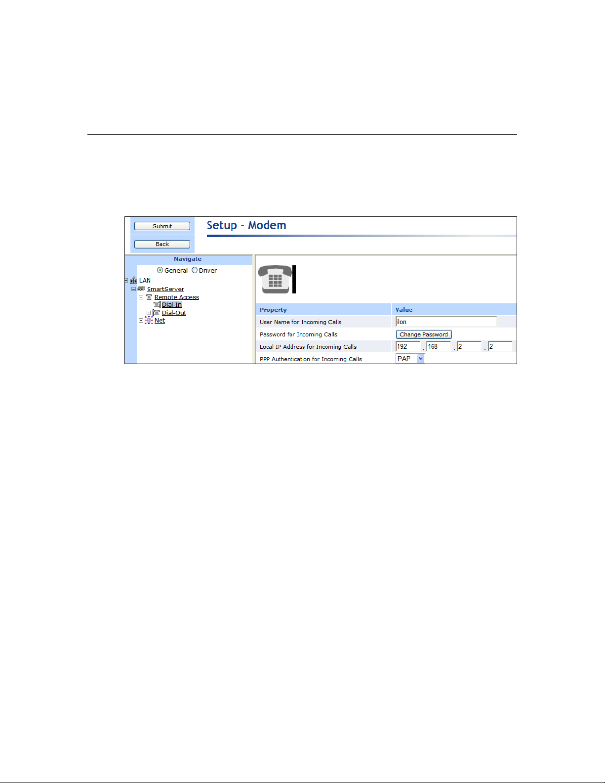
PIN Number
If you are using an External GSM modem, enter the PIN (maximum 30
characters) to be sent to the external modem in order for it to transmit or
receive calls.
User Name for
Incoming Calls
Enter the user name (maximum 30 characters) that a caller must provide to
connect to the SmartServer via modem. The default user name is ilon.
Change this name for enhanced security.
Password for
Incoming Calls
Click Change Password to enter and then re-enter the password
(maximum 30 characters) that the caller must provide to connect to the
SmartServer via modem. The default password is ilon. Change this
password for enhanced security.
Local IP Address for
Incoming Calls
Enter the IP address that will be assigned to incoming calls by the
SmartServer. The default IP address is 198.162.2.2.
Note: The local IP address must be outside the range of the SmartServer’s
Ethernet IP connection. For example, do not use 192.168.1.0 to
192.168.1.255 for the local IP address if you are using the SmartServer’s
default IPv4 address (192.1.168.222).
In addition, do not enter 0 or 254 in the last field of the IP address because
other services may need to use these values. In addition, do not enter 255
in the last field of the IP address because the modem will not be able to
ping the SmartServer.
3. Click Submit.
Configuring Dial-in Connections
You can enable the SmartServer to be accessed remotely via a dial-in connection. To do this, follow
these steps:
1. In the navigation pane directly under the Remote Access modem icon, click the Dial-In modem
icon.
2. Set the following properties:
SmartServer 2.2 User’s Guide 59
Page 59

PPP Authentication
for Incoming Calls
Select the PPP (Point-to-Point Protocol) authentication type to validate the
identity of a remote client. You have three choices:
None. No PPP authentication is used for incoming calls.
PAP (Point-to-Point Access Protocol). PAP uses unencrypted ASCII
encoding to transmit user names and passwords over the network.
Because PAP is considered insecure, only use it if CHAP is not
available, or if the user name and password that the user submitted to
PAP must be sent to another program without encryption. This is the
default.
CHAP (Challenge Handshake Authentication Protocol). CHAP uses
a three-way handshake to validate a remote client when the
connection is established and may validate it again anytime
afterwards. This is the recommended PAP authentication type.
Dialing Type
Select whether the SmartServer’s modem will dial using touch-tone or
pulse dialing. The default dialing type is Tone.
Dialing Prefix
Enter a prefix (maximum 30 digits) if the SmartServer is connected to a
phone system that requires a code to be dialed to reach an outside line. By
default, this field is blank.
Delay After Prefix
If you entered a dialing prefix, enter the delay (in seconds) between the
prefix and the phone number being dialed. The default delay is 0 seconds.
You must reboot the SmartServer for changes to this property to take
effect
Dial Tone Waiting
Enables the modem to wait for a dial tone before dialing out.
3. Click Submit.
Configuring Dial-out Connections
You can enable the SmartServer to connect to a TCP/IP network via a dial-out modem connection so
that it can connect to other host devices. To do this, specify the phone number or GPRS service to be
used by your SmartServer’s modem to dial out. To configure the dial-out connections, follow these
steps:
1. In the navigation pane directly under the Dial-in modem icon, click the Dial-Out modem icon.
The properties that you can set depend on whether the SmartServer is using its internal analog
modem or an external GSM modem.
2. If you are using an Internal Analog modem, set the following properties:
60 Configuring and Managing the SmartServer
Page 60

Access Point Name
(APN)
Set the APN (maximum 64 characters), which is required by most
GPRS service providers. The APN can be a valid IP address, or a valid
hostname and domain suffix pair.
Quality of Service
(QoS)
Set the QoS string (maximum 30 characters), which is required by most
GPRS providers.
QoS refers to the control mechanisms that can provide different priority
to different users or data flows, or guarantee a certain level of
performance to a data flow in accordance with requests from an
application program.
3. If you are using an External GSM modem, set the following properties:
4. Click Submit.
Creating Dial-Out Connections
You can create a dial-up connection for each phone number or GPRS service to which the SmartServer
is connected. The SmartServer contains two sample dial-out connections: Freenet and T-Online.
You can configure these connections by expanding the Dial-Out modem icon and then clicking them,
or you can create new dial-out connections. You can delete these sample connections if you do not
plan on using them.
To create a new dial-up connection, follow these steps:
1. In the navigation pane, right-click the Dial-Out modem icon and then click Add Connection on
the shortcut menu.
2. The Enter Name dialog opens. Enter a name for the connection and then click OK.
SmartServer 2.2 User’s Guide 61
Page 61

Connection Name
Enter a name for the dial-out connection (maximum 30 ASCII
characters), such as the name of the ISP. The name may not include
the ‘&’, ‘<‘, and ‘>‘ characters.
3. The Setup – Connection Web page opens and the connection is added to the bottom of the
Dial-Out tree.
4. Click Submit.
5. Set the following properties for the dial-out connection:
62 Configuring and Managing the SmartServer
Page 62

Phone Number
Enter the phone number to call when this dial-out connection is used.
If you are using an external GSM modem, you can select the
following options to enable a GPRS connection with this number:
GPRS. Uses the GPRS protocol to transmit data instead of an
analog phone call. A connection will be established whenever the
SmartServer attempts to contact a server with the dial-up
connection. Once the transaction with the server is complete, the
connection will be dropped. See the documentation for your
GSM modem for more information about the GPRS protocol.
Persistent GPRS. Uses the GPRS protocol to transmit data, but
the GSM modem requests a network connection as soon as the
SmartServer boots, and keeps it open as long as the ISP allows it.
Note: Many GPRS service providers require a phone number that
must be dialed when establishing a connection, such as *99***1#.
Consult your ISP for details on configuring the properties of your
GPRS connections.
Note: To use the Firefox Web browser to access the SmartServer
Web pages via GPRS, you must modify your user agent string in
the Web browser. To do this, follow these steps:
1. Enter about:config in the address bar of the Firefox Web
browser.
2. In the Filter box, enter general.useragent.extra.firefox.
3. Double-click the general.useragent.extra.firefox preference
name.
4. Enter the following value in the Enter String Value dialog:
Mozilla/4.0 (compatible; MSIE 8.0; Windows NT 5.1;
Trident/4.0; .NET CLR 1.1.4322; .NET CLR 2.0.50727;
.NET CLR 3.0.4506.2152; . NET CLR 3.5.30729)
5. Click OK.
User Name
Enter the user name (maximum 30 ASCII characters) to be used by
the SmartServer when connecting to an ISP. The user name may not
include the ‘&’, ‘<‘, and ‘>‘ characters. This field is blank by default.
Password
Click Change Password to enter and then re-enter the password
(maximum 30 ASCII characters) to be used by the SmartServer when
connecting to an ISP. The password may not include the ‘&’, ‘<‘, and
‘>‘ characters. This field is blank by default.
Remote DNS Server
Enter the IP address of the DNS server to be used when using this
dial-out connection. Select the Obtain Automatically check box to
obtain the DNS server address from the PPP server when establishing
the connection.
Disconnect if Idle for
Enter the length of time (between 0.0 and 6553.5) seconds that the
connection may be idle before it is disconnected. Once a PPP
connection is established, it will not be released until it has been idle
for this amount of time. This means that if data is being constantly
sent over a PPP connection, the connection will never be dropped and
any data that needs to use a second PPP connection may never be sent.
SmartServer 2.2 User’s Guide 63
Page 63

The default time is 30.0 seconds.
PPP Authentication for
Outgoing Calls
Select the PPP authentication type to be used when connecting to an
ISP. You have three choices:
Automatic. The SmartServer automatically selects the
authentication type to be used when connecting to the ISP. This
is the default.
PAP (Point-to-Point Access Protocol). PAP uses unencrypted
ASCII encoding to transmit user names and passwords over the
network. Because PAP is considered insecure, only use it if
CHAP is not available, or if the user name and password that the
user submitted to PAP must be sent to another program without
encryption.
CHAP (Challenge Handshake Authentication Protocol). CHAP
uses a three-way handshake to validate a remote client when the
connection is established and may validate it again anytime
afterwards. This is the recommended PAP authentication type.
Dynamic DNS
Enables you to use a DNS server that has a dynamic IP address. The
SmartServer only supports www.dyndns.org as a dynamic DNS
(DDNS) provider. You must set up an account on this site and set up
the DDNS hostname.
For example, consider a case where the SmartServer should be
accessible via the hostname “ilon100example.dyndns.org” when a
persistent GPRS connection is established. The user needs to use the
account with the name <UserName> and the password <Password>.
In this case, perform the following steps:
1. Set up a user account at www.dyndns.org with the user name
<UserName> and password <Password>.
2. Set up a dynamic DNS entry for the host
“ilon100example.dyndns.org”.
3. Set up a persistent GPRS connection with this DDNS.
4. Test these settings by opening the following Web page:
http://ilon100example.dyndns.org. You should receive the normal
SmartServer Web pages via GPRS.
Hostname
Enter the hostname of the SmartServer that is registered at
www.dyndns.org. You only need to set this property if you are
enabled dynamic DNS service.
User Name
Enter the user name (maximum 30 ASCII characters) defined for the
DDNS server at www.dyndns.org. You only need to set this field if
you are using dynamic DNS service. The user name may not include
the ‘&’, ‘<‘, and ‘>‘ characters. This property is blank by default.
6. If you enabled dynamic DNS by selecting the Dynamic DNS checkbox, set the following
properties:
64 Configuring and Managing the SmartServer
Page 64

Password
Click Change Password to enter and then re-enter the password
(maximum 30 ASCII characters) defined for the DDNS server at
www.dyndns.org. You only need to set this property if you are using
dynamic DNS service. The password may not include the ‘&’, ‘<‘,
and ‘>‘ characters. This property is blank by default.
Hostname (complete)
Enter the hostname or IP address of the Web server provided by the
ISP for the GPRS connection.
Check Interval
Enter the amount of time after which the SmartServer connects to the
ISP automatically.
Retry Time
Set the interval (in seconds) that network messages wait for
confirmation before being re-sent over the network. The default time
retry time is 120 seconds.
Retry Count
Set the number of times a network message is re-sent when no
confirmation is received.
Verify Mode
Select the method in which the SmartServer simulates internet activity
in order to verify that the GPRS connection is active. You have the
following three choices:
Default. The SmartServer pings the IP address of the Web
server, and it opens a TCP connection to the HTTP port (80) of
the Web server. If either check succeeds, the GPRS connection is
active.
Ping Host. The SmartServer pings the IP address of the Web
server. This is similar to the ‘ping’ command in Linux or
Windows.
Check HTTP Connection. The SmartServer opens a TCP
connection to the HTTP port (80) of the Web server.
If the GPRS connection is lost, the SmartServer restarts the modem.
7. If you enabled a persistent GPRS connection for the phone number you entered by selecting the
Persistent GPRS check box, you can select the GPRS Check checkbox to set the following
properties:
Once you have created and configured a dial-out connection, you can add host devices to the
connection (remote SmartServers, OpenLNS Servers, e-mail servers, time servers, IP-852
Configuration Servers, and Web Connection Target servers). For information on how to do this, see
the next section, Adding Host Devices.
Adding Host Devices
You can connect host devices to your local SmartServer through the SmartServer’s Ethernet
connection, or though a dial-up connection that you have added to the SmartServer’s built-it analog
SmartServer 2.2 User’s Guide 65
Page 65

modem (applicable models) or an external GSM modem connected to the SmartServer’s RS-232 serial
port. The host devices you can add to the LAN consist of remote SmartServers, OpenLNS
Servers, e-mail servers, time servers, IP -852 Configuration Servers, and Web Connection Target
servers (Web servers that can process SOAP requests).
To add a host device to the SmartServer’s Ethernet connection, right-click the LAN icon (the first icon
at the top of the navigation pane in the left frame), point to Add Host, and then select Server or
SmartServer. Select Server to add an OpenLNS Server, e-mail server, time server, IP-852
Configuration Server, or Web Connection Target server to the LAN. Select SmartServer to add a
remote SmartServer to the LAN.
To add a host device to a dial-up connection on the SmartServer, you right-click the icon representing
the dial-out connection to which the host device is to be added, point to Add Host, and then select
Server or SmartServer.
When you add a host device, it appears one level below the LAN or dial-out connection in the
navigation pane. In addition, if you add a remote SmartServer to the LAN, the network attached to it is
listed one level below its SmartServer icon. If you add an OpenLNS Server to the LAN, its networks
(OpenLNS network databases) are listed one level below its LNS Server icon. If you add an e-mail,
time, IP-852 configuration, or Web Connection Target server to the LAN, An icon representing the
specific host device is listed one level below its generic server icon.
You can add multiple services to a given host device. For example, the OpenLNS Server you add to
the LAN might also serve as an IP-852 Configuration Server and a Web Connection Target server.
66 Configuring and Managing the SmartServer
Page 66

LAN
The LAN icon corresponds to the SmartServer’s 10/100-BaseT Ethernet
connection. This connection is always the first icon shown in the
navigation pane, and it cannot be deleted
Host Devices
Host devices represent the various servers on the LAN. Host devices
include your local SmartServer and may include remote SmartServers,
OpenLNS Servers, e-mail (SMTP) servers, time servers (SNTP), IP-852
Configuration Servers, and Web Connection Target servers.
Local SmartServer
Your local SmartServer is always the second icon shown in the navigation
pane, and it cannot be deleted. From this icon, you can configure your
local SmartServer; access the SmartServer’s built-in applications; and
manage, monitor, and control the devices connected to your local
SmartServer. The remote access (dial-up) connections and the network
attached to your local SmartServer are listed one level below the local
SmartServer icon.
Remote
SmartServers
You can add remote SmartServers to the LAN and manage them from
your local SmartServer. You can also create Web connections between
the data points on your local SmartServer to the data points on the remote
SmartServers (called peer-to-peer connections).
Remote SmartServers are represented by SmartServer icons that include
the IP addresses or hostnames of their respective remote SmartServers.
The LAN, the host devices on the LAN, and the networks available on the host devices are further
described as follows:
SmartServer 2.2 User’s Guide 67
Page 67

OpenLNS Servers
You must add an OpenLNS Server to the LAN in order to add the data
points of external devices to the SmartServer’s built-in applications and to
your custom SmartServer Web pages. In addition, you need to add an
OpenLNS Server to the LAN in order to keep your local SmartServer
synchronized with an OpenLNS network database and use OpenLNS
network management services to manage the network attached to your
local SmartServer. You can also create Web connections between your
local SmartServer and OpenLNS Servers (called LNS uplink connections).
OpenLNS Servers are represented by LNS Server icons that include the IP
addresses of their respective OpenLNS Servers.
E-mail server
You can use an SMTP server to have the SmartServer send e-mail
messages to a technician, maintenance company, or other personnel when
a data point is an alarm condition. You must also add Alarm Generator
and Alarm Notifier functional blocks to the SmartServer’s i.LON App
(Internal) device for the SmartServer to send e-mail notifications.
SMTP servers are represented by a server icon that includes the IP address
or hostname of the server and an SMTP icon listed directly below it.
Time server
You can use an SNTP server to synchronize the time and date of the
SmartServer and the other host devices on the LAN to a common base.
SNTP servers are represented by a server icon that includes the IP address
or hostname of the server and an SNTP icon listed directly below it.
IP-852
Configuration
Server
You can add an IP-852 Configuration Server to the LAN to enable a
SmartServer with IP-852 routing activated and other IP-852 devices such
as OpenLNS Servers and i.LON 600 LONWORKS/IP servers to
communicate with each other over a high-performance backbone channel.
An IP-852 Configuration Server is represented by an IP-852 server icon
that includes the IP address of the IP-852 Configuration Server.
Note: You only need to add an IP-852 Configuration Server if you do not
plan on using the default port on the SmartServer (1628) used for
receiving messages from the IP-852 Configuration Server.
Web Connection
Target Server
You can add an Web Connection Target Server to send data logs, alarm
logs, event scheduler logs, or any user-defined file from your SmartServer
to a central enterprise system via a Web connection (called an enterprise
connection).
Networks
You can manage the channels, devices, functional blocks, and data points
on the network attached to your local SmartServer, the networks attached
to remote SmartServers on the LAN, and in the networks in the OpenLNS
Servers on the LAN.
SmartServer
Network
By default, the network attached to a SmartServer is represented by the
SmartServer network icon, and it is named Net. Once you synchronize
your SmartServer to an OpenLNS network database, this icon changes to
an OpenLNS network icon ( ) and is re-named to the name of the
OpenLNS network database.
OpenLNS network
(Database)
By default, the networks in an OpenLNS Server are represented by
OpenLNS network icons that include the names of their respective
OpenLNS network databases. Networks originally created in the
SmartServer tree are represented by SmartServer network icons ( ) in
the OpenLNS tree.
68 Configuring and Managing the SmartServer
Page 68

IP or Hostname
Enter the IP address or hostname of the remote SmartServer. The default
Adding a Remote SmartServer to the LAN
You can add another SmartServer to the LAN, and then manage the remote SmartServer and manage,
monitor, and control the network attached to it from the Web interface of your local SmartServer. In
addition, you can create Web connections between the data points on your local SmartServer to those
on the remote SmartServer. The Web connections will keep the values of the data points
synchronized. For more information on creating and using Web connections, see Creating Web
Connections in Chapter 4, Using the SmartServer Web Interface.
To add a remote SmartServer to the LAN, follow these steps:
1. Verify that the remote SmartSever has a unique hostname relative to the LAN—the remote
SmartServer cannot have the same hostname as the local SmartSever. To change the hostname of
a SmartServer, do the following:
For a SmartServer in an LNS managed network, change the SmartServer’s hostname with
OpenLNS CT or another OpenLNS tool.
For a SmartServer in a standalone managed network, change the hostname in its Setup –
Local SmartServer TCP/IP Web page or the console application.
2. Right-click the LAN icon or a dial-out connection icon, point to Add Host, and then click
SmartServer on the shortcut menu.
3. The Setup – Remote SmartServer Web page opens, and a SmartServer icon is added one level
below the LAN icon at the bottom of the navigation pane or one level below the dial-out
connection icon.
4. Configure the following properties for the remote SmartServer:
SmartServer 2.2 User’s Guide 69
Page 69

hostname is SmartSever.
Host Property
SOAP Path
Enter the path on the remote SmartServer to which SOAP messages
should be transmitted. This is typically the location of the WSDL or
ASMX file on the SmartServer where it receives SOAP messages. The
default path is /WSDL/iLON100.WSDL (the default location of the
WSDL file on a SmartServer).
HTTP Port (Web
Server/SOAP)
Enter the port that the remote SmartServer uses to serve HTTP requests
(SOAP and WebDAV). The default value is 80, but you may change it to
any valid port number. Contact your IS department to ensure your
firewall is configured to allow access to the server on this port.
Select the SSL option to create a secure Web connection. Enter the port
number to use for the SOAP interface. The default port used for SSL is
443, but you may change it to any valid port number.
Retry Time
Set the amount of time (in seconds) after which the remote SmartServer
will stop attempting to resend failed Web Connection connection
messages. The default value is 120 seconds.
The remote SmartServer automatically attempts to resend failed Web
Connection connection messages every 45 seconds.
Use Connection
Timeout
Set the maximum period of time (in seconds) that the remote SmartServer
waits for a response to a SOAP request from the local SmartServer’s Web
server before the transaction is canceled and a timeout error is thrown.
By default, the connection timeout is 2 seconds—even if this check box is
cleared. If you select this check box, the default timeout is 120 seconds.
SOAP User Name
Optionally, you can enter a user name to be used for logging in to the
remote SmartServer.
Alternatively, you configure the user name and password using the i.LON
Web Server Security and Parameters program, or by manually
configuring the webparams.dat file located at the root level of the
SmartServer’s flash disk. See Appendix C for more information on using
the i.LON Web Server Security and Parameters program.
SOAP Password
If you create a user name, click Change Password to enter the password
to be used for logging in to the remote SmartServer.
Format Values in
Web Connection
SOAP Messages
Using
Select how data point values are formatted in SOAP messages sent to this
remote SmartServer via Web connections. You have two choices:
Data Point Format. Data point values are formatted based on the
SNVT, UNVT, SCPT, or UCPT defined for the data point.
Raw HEX. Data point values are transmitted in raw hexadecimal
format.
5. Click Submit to save the changes.
To delete a remote SmartServer, right-click the SmartServer icon representing the remote SmartServer,
click Delete on the shortcut menu, and then click Submit.
Adding an OpenLNS Server to the LAN
You can add an OpenLNS Server or LNS Server to the LAN and then use the LNS Proxy Web service
to synchronize your SmartServer an OpenLNS network database, add the data points of external
70 Configuring and Managing the SmartServer
Page 70

Host Property
devices in OpenLNS managed networks to the SmartServer’s built-in applications and to your custom
SmartServer 2.2 Web pages, and use OpenLNS network management services to manage the network
attached to your local SmartServer.
You can also create Web connections between your local SmartServer and an OpenLNS Server on the
LAN (called LNS uplink connections). When the value of a data point on your local SmartServer
changes, an uplink connection to the destination OpenLNS Server is initiated and the data point value
is transmitted to that OpenLNS Server. For more information on creating and using Web connections,
see Creating Web Connections in Chapter 4, Using the SmartServer Web Interface.
To add an OpenLNS Server or LNS Server to the LAN, follow these steps:
1. Verify that EES 2.2 and an OpenLNS Server or LNS Server have been installed on your computer.
See Chapter 1 of the Echelon Enterprise Services 2.2 User’s Guide for how to perform these
installations.
2. Right-click the LAN icon or a dial-out connection icon, point to Add Host, and then click Server
(LNS, Email, Time, IP-852, WebTarget) on the shortcut menu.
Note: If IP-852 routing is activated and enabled on the SmartServer and the IP-852 Configuration
Server is installed on the OpenLNS Server computer, click the IP-852 Configuration Server icon
( ), click LNS Proxy, and then skip to step 5 in order to configure the properties of the
OpenLNS Server.
3. The Setup – Host Web page opens, and a server icon is added one level below the LAN icon at
the bottom of the navigation pane or one level below the dial-out connection icon.
4. Enter the IP address or hostname of the OpenLNS Server or LNS Server and then click LNS
Proxy. The server icon on the tree becomes an LNS Server icon and the Setup – OpenLNS
Server Web page opens.
5. Configure the following OpenLNS Server properties:
SmartServer 2.2 User’s Guide 71
Page 71

SOAP Path
Enter the path on the OpenLNS Server to which SOAP messages are
transmitted via the LNS Proxy Web service. The default path is
/LnsProxy/LnsProxyService.
HTTP Port (Web
Server/SOAP)
Enter the port on the SmartServer used for accessing the LNS Proxy Web
service. The default port is 80. Contact your IS department to ensure
your firewall is configured to allow access to the server on this port.
Note: If you modify this property, you need to reboot the SmartServer to
implement the change.
Use Connection
Timeout
Set the maximum period of time (in seconds) that the LNS Proxy Web
service waits for a response to a SOAP request from the local
SmartServer’s Web server before the transaction is canceled and a timeout
error is thrown.
By default, the connection timeout is 2 seconds if this option is cleared. If
you select this option, the default timeout is 120 seconds.
User Name
Optionally, enter a user name to be used by the SmartServer for accessing
the LNS Proxy Web service. The default user name is ilon.
SOAP Password
Optionally, you can click Change Password to change the password used
by the SmartServer for accessing the LNS Proxy Web service. The
default password is ilon.
Format Values in
Web Connection
SOAP Messages
Using
Select how data point values are formatted in SOAP messages sent to this
OpenLNS Server via Web connections. You have two choices:
Data Point Format. Data point values are formatted based on the
SNVT, UNVT, SCPT, or UCPT defined for the data point.
Raw HEX. Data point values are transmitted in raw hexadecimal
format.
6. Click Submit to save the changes. Click Back to leave all fields unchanged.
7. If you are using Internet Explorer 7, enable your Web browser to access the LNS Proxy Web
service on the OpenLNS Server computer. To do this, follow these steps:
a. Add the locations of your local SmartServer and the OpenLNS Server on which the LNS
Proxy Web service is installed as trusted sites. To do this, click Tools, click Internet
Options, click the Security tab, click Trusted Sites, and then click Sites. Clear the Require
Service Verification check box.
By default, the IP address of your local SmartServer appears in the Add this Website to the
Zone box. Click Add to add the IP address of your local SmartServer. Enter the IP address
of the LNS Proxy Web service in the Add this Website to the Zone box, click Add, click
Close, and then click OK.
b. Enable your Web browser to access sites over other domains. To do this with Internet
Explorer 7, click Tools, click Internet Options, click the Security tab, and then click
Custom. Under the Miscellaneous category, select Enable or Prompt for the Access data
sources across domains property.
Note: If you are using Internet Explorer 7 and you do not complete step 2, the Cannot
Access Remote Host dialog appears when you try to expand the LNS Server icon or
synchronize the SmartServer to an OpenLNS network database. If you are using Internet
Explorer 8, Chrome, or Firefox, you do not need to complete this step.
5. You can now expand the LNS Server icon to show the networks, channels, devices, functional
blocks, and data points on your OpenLNS Server. It may take a minute to show the networks on
72 Configuring and Managing the SmartServer
an OpenLNS Server after you initially expand the LNS Server icon.
Page 72

You can configure the object in the OpenLNS tree and the changes are automatically transmitted
to the OpenLNS Server. In addition, when you modify an OpenLNS network database with
another OpenLNS client such as OpenLNS CT, the OpenLNS tree will be updated because the
SmartServer polls the OpenLNS network database and processes the changes.
For more information on using the SmartServer to manage the objects in an OpenLNS network
database, see Chapter 5, Using the SmartServer as a Network Integration Tool.
6. You can now operate the SmartServer in LNS mode and select an OpenLNS or LNS network
database to be synchronized to your SmartServer. See Configuring a LonWorks Network in
Chapter 5 for more information on how to do this.
7. You now add the external network variables and configuration properties in the OpenLNS tree to
an embedded application on a SmartServer (your local SmartServer or a remote SmartServer that
you have added to the LAN). See Adding Data Points to SmartServer Applications in Chapter 4,
Using the SmartServer Web Interface, for more information on adding external network variables
and configuration properties to the SmartServer’s built-in applications.
To delete an OpenLNS Server, right-click the OpenLNS Server, click Delete on the shortcut menu, and
then click Submit.
Troubleshooting the LNS Proxy Web Service
If you cannot synchronize the SmartServer to an OpenLNS or LNS network database, Echelon
Enterprise Services 2.2 (EES 2.2) may not have been installed or configured correctly, or a firewall
may be blocking access. Follow these steps to correct the problem:
1. Verify that the SmartServer and the LNS Proxy Web service are using the same HTTP port on the
OpenLNS Server computer for SOAP communication. To do this follow these steps:
a. Open the Setup – OpenLNS Server Web page. To do this, click the LNS Server icon in the
tree view on the left side of the SmartServer Web interface.
b. The port used by the SmartServer to communicate with the LNS Proxy Web service is
specified in the HTTP Port (Web Server / SOAP) property. The default port is 80.
c. Right-click the Enterprise Services tray icon in the notification area on the desktop of the
OpenLNS Server computer, and then click Options on the shortcut menu.
d. The port used by the LNS Proxy Web service on the OpenLNS Server computer is listed in
the Port Number property in the Connection tab. The default port is 80.
2. Verify that the EES tray tool icon is red, meaning that EES 2.2 is running. If the icon is gray and
the ToolTip states “SmartServer Enterprise Services OFF”, EES 2.2 is not running. To start EES
2.2, right-click the Enterprise Services tray icon and click Start Service on the shortcut menu.
3. If you selected the LNS Auto network management service in the Setup – LON Network Driver
Web page and a firewall is blocking access to the LNS Proxy Web Services, do the following on
both your OpenLNS Server computer and your remote OpenLNS client (if being used):
a. Open the HTTP port to be used for the LNS Proxy Web Services. To do this, open the
Control Panel, click Security Center, click Services, click Windows Firewall, click the
Exceptions tab, and then click Add Port. Enter LNS Proxy (or some other meaningful name)
in the Name box, enter the selected HTTP port in the Port box, and then click OK.
b. If you are using a third-party firewall, add the Tomcat 6 executable as an exception. The full
path of the Tomcat 6 executable is
LonWorks\iLON\EnterpriseServices\Appserver\bin\tomcat6.exe by default.
c. Try to expand the LNS Server icon in the navigation pane on the left side of the SmartServer
Web interface. If you cannot expand the OpenLNS Server, either proceed to step 4, or open
the Setup – LON Network Driver Web page and change the Network Management
Service property to LNS Manual.
SmartServer 2.2 User’s Guide 73
Page 73

4. Browse to http://<OpenLNS Server Computer IP Address>/EES/AdminService/v4.0/index.htm,
which is the IP address of the i.LON AdminServer tool that is installed on your OpenLNS Server
computer by EES 2.2. For example, if the IP address of your OpenLNS Server computer is
10.2.124.30, enter http://10.2.124.30/EES/AdminService/v4.0/index.htm.
Note: Browse from a computer that is on the same side of the firewall as the SmartServer and the
computer used to access the SmartServer Web pages.
If the i.LON AdminServer tool opens, the SmartServer should be able to communicate with
the LNS Proxy Web Service. Use the Add or Remove Programs Control Panel application to
verify that the version of EES 2.2 matches the SmartServer firmware version. The
SmartServer firmware version is displayed at the bottom right side of the SmartServer Web
pages. You can also view this information by clicking Setup and then clicking System Info
in the SmartServer Web pages, or right-clicking the local SmartServer and clicking System
Info on the shortcut menu.
If the i.LON AdminServer tool does not open, un-install and then re-install EES 2.2. In
addition, verify that there are no port conflicts with any other applications.
Adding an E-mail (SMTP) Server to the LAN
You can add an e-mail (SMTP) server to the LAN to have the SmartServer automatically send e-mail
notifications when a data point is an alarm condition. You must also add Alarm Generator and Alarm
Notifier functional blocks to the SmartServer’s i.LON App (Internal) device and configure them for
the SmartServer to send e-mail notifications. See Chapter 6, Alarming, for more information on
configuring the SmartServer’s alarming applications.
To add an e-mail server to the LAN, follow these steps:
1. Right-click the LAN icon or a dial-out connection icon, point to Add Host, and then click Server
(LNS, Email, Time, IP-852, WebTarget) on the shortcut menu, or if are you adding the time
service to an existing server on the LAN, skip to step 4.
2. The Setup – Host Web page opens, and a server icon is added one level below the LAN icon at
the bottom of the navigation pane or one level below the dial-out connection icon.
3. Enter the IP address or hostname of the e-mail (SMTP) server.
74 Configuring and Managing the SmartServer
Page 74

Property
Name
Enter a name for the SMTP server. This field is blank by default.
4. Optionally, select the Use Connection Timeout option and enter the maximum period of time (in
seconds) that the e-mail (SMTP) server waits for a response to a SOAP request from the local
SmartServer’s Web server before the transaction is canceled and a timeout error is thrown. By
default, the connection timeout is 2 seconds if this option is cleared. If you select this option, the
default timeout is 120 seconds.
5. Click Submit. The server icon in the tree is updated with the IP address or hostname you entered.
6. Right-click the new server icon, point to Add Service, then and click E-Mail (SMTP) on the
shortcut menu.
7. The Setup – Mail Web page opens.
8. Configure the following e-mail (SMTP) server properties:
SmartServer 2.2 User’s Guide 75
Page 75

E-mail Server Port
Enter the port used by the SmartServer to send e-mail messages.
The default value is 25. Contact your IS department to verify that
your firewall will allow you to access the e-mail server on this
port.
Use as Default
Makes the e-mail server the default e-mail service for the
SmartServer. If this is the first e-mail service created on the
SmartServer this option will be set by default. If another e-mail
service is currently designated as the default and this check box is
selected, the default designation will be removed from the first
e-mail service when you click Submit.
Source E-mail
Address
Enter the string that will appear in the From field of e-mail
messages sent through this service (for example
lonfloor1@echelon.com). This field is blank by default.
User Name
If the SMTP server requires authentication, enter the user name for
logging in to the SMTP server. The SmartServer and the SMTP
server will automatically negotiate the authentication mechanism
to be used (PLAIN, LOGIN, or CRAM-MD5). The SmartServer
does not support the POP before SMTP authentication mechanism.
Password
If the SMTP server requires authentication, click Change
Password to enter the password for logging in to the SMTP
server.
9. Click Submit to save the changes.
To delete an e-mail (SMTP) server, right-click the generic server icon if the sever is used exclusively
for the e-mail service, or right-click the e-mail service icon if the server is used for other services, click
Delete on the shortcut menu, and then click Submit.
Adding a Time (SNTP) Server to the LAN
You can add a time (SNTP) server to the LAN to synchronize the date and time on the SmartServer
and all other devices on the LAN to a common base. This ensures that message packets overcome the
latencies posed by large IP networks and reach their destinations. The time (SNTP) server you add
must be running at the specified location. For more information on time and frequency services and a
list of available public time (SNTP) servers, go to http://ntp.isc.org/bin/view/Servers/WebHome.
Tip: You can install Tardis2000, a shareware program available at www.kaska.demon.co.uk, and
synchronize it to another SNTP server or the local time on your computer. If you synchronize it to the
local time on your computer, you can then use the loopback address of your local computer (127.0.0.1)
as an SNTP server on your SmartServer.
Note: If you are using the SmartServer as an IP-852 router and using a channel timeout for that IP-852
channel, you can let the IP-852 Configuration Server manage the SNTP time server configuration on
the SmartServer. See the IP-852 Channel User’s Guide for details on this. If the IP-852 Configuration
Server sets a time server on the SmartServer, that time server will automatically show up in the
SmartServer Web pages, and will override any time server configurations you have made with the
SmartServer Web pages.
To add a time (SNTP) server to the LAN, follow these steps:
1. Right-click the LAN icon or a dial-out connection icon, point to Add Host, and then click Server
(LNS, Email, Time, IP-852, WebTarget) on the shortcut menu, or if are you adding the time
service to an existing server on the LAN, skip to step 4.
76 Configuring and Managing the SmartServer
Page 76

2. The Setup – Host Web page opens, and a server icon is added one level below the LAN icon at
the bottom of the navigation pane or one level below the dial-out connection icon.
3. Enter the IP address or hostname of the time (SNTP) server.
4. Optionally, select the Use Connection Timeout option and enter the maximum period of time (in
seconds) that the time (SNTP) server waits for a response to a SOAP request from the local
SmartServer’s Web server before the transaction is canceled and a timeout error is thrown. By
default, the connection timeout is 2 seconds if this option is cleared. If you select this option, the
default timeout is 120 seconds.
5. Click Submit. The server icon in the tree is updated with the IP address or hostname you entered.
6. Right-click the server icon, point to Add Service, then and click Time (SNTP) on the shortcut
menu.
7. The Setup – TimeService Web page opens.
SmartServer 2.2 User’s Guide 77
Page 77

Property
Time Server Port
The port used by the SmartServer to receive time data. This default value
is 123, and it cannot be changed. Contact your IS department to make
sure that your firewall is configured to allow you to access the time server
on this port.
Time
Synchronization
Mode
Select the frequency in which the SmartServer is synchronized to the
SNTP server. You have four choices:
Automatic. The SmartServer is synchronized every 1 to 15 minutes
and remains within 100ms of the SNTP server. This is the default,
and it can be used for both LAN and dial-out (modem and GPRS)
connections.
Sync when dial-up is active. The SmartServer clock is synchronized
when a dial-out connection is established. This option can only be
used for dial-out connections (modem and GPRS).
Fixed interval. The frequency in which the SmartServer is
synchronized is based on the value in the Synchronization Interval
property. This option can only be used for Ethernet connections.
Disabled. The SmartServer is not synchronized with the SNTP
server.
Time
Synchronization
Interval
Set how often the SmartServer clock is synchronized with the SNTP
server. This option is only available if Fixed Interval is the selected
synchronization method. The default synchronization interval is 12
hours.
Use As
Select whether this time server is the Default or the Backup time server.
If this is the first time service created on the SmartServer, this option is set
to Default. If another time service is currently designated as the default
and you select Default, the default designation will be removed from the
other time server when you click Submit.
8. Configure the following time (SNTP) server properties:
9. Click Submit to save the changes.
78 Configuring and Managing the SmartServer
Page 78

To delete a time (SNTP) server, right-click the generic server icon if the sever is used exclusively for
the time service, or right-click the time service icon if the server is used for other services, click Delete
on the shortcut menu, and then click Submit.
Adding an IP-852 Configuration Server to the LAN
If you licensed and activated IP-852 routing on your SmartServer but you are not using the standard
port on the SmartServer for it (1628), you can add an IP-852 Configuration Server to the LAN.
Adding an IP-852 Configuration Server to the LAN enables a SmartServer with IP-852 routing
activated to communicate with other IP-852 devices over a high-performance IP-852 backbone
channel. The other IP-852 devices may include other SmartServers with IP-852 routing licensed,
i.LON 600 IP-852 routers, OpenLNS Servers, LNS Servers, and OpenLNS or LNS tool computers.
Note: If you are using the standard port for IP-852 routing, you can skip this section and use the
IP-852 Configuration Server program to add the SmartServer to an IP-852 channel. The IP-852
Configuration Server stores the configuration of the IP-852 channel, including the IP addresses of all
the IP-852 devices installed on the channel. You will initially configure the IP-852 channel with the
IP-852 Configuration Server, and the IP-852 Configuration Server must be running anytime you
change the configurations of the IP-852 devices on the IP-852 channel. You can run the IP-852
Configuration Server on any computer with access to the IP network containing the IP-852 channel.
The software required to run the IP-852 Configuration Server is included with the SmartServer
software. For more information on the IP-852 Configuration Server and using this program, see the
IP-852 Channel User’s Guide.
To add an IP-852 Configuration Server to the LAN, follow these steps:
1. Right-click the LAN icon, point to Add Host, and then click Server (LNS, Email, Time, IP-852,
WebTarget) on the shortcut menu, or if are you adding the IP-852 Configuration Server to an
existing server on the LAN, skip to step 4.
2. The Setup – Host Web page opens, and a server icon is added one level below the LAN icon at
the bottom of the navigation pane.
3. Enter the IP address or hostname of the IP-852 Configuration Server.
4. Optionally, select Use Connection Timeout and enter the maximum period of time (in seconds)
that the IP-852 Configuration Server waits for a response to a SOAP request from the local
SmartServer 2.2 User’s Guide 79
Page 79

SmartServer’s Web server before the transaction is canceled and a timeout error is thrown. By
default, the connection timeout is 2 seconds if this option is cleared. If you select this option, the
default timeout is 120 seconds.
5. Click Submit. The server icon in the tree is updated with the IP address or hostname you entered.
6. Right-click the new server icon, point to Add Service, then and click IP-852 Configuration
Server on the shortcut menu.
7. The IP-852 Configuration Server Property Web page opens. Enter the port used by the IP-852
Configuration Server to receive messages form the SmartServer in the IP-852 Configuration
Server Port box. The default port is 1629.
8. Click Submit to save the changes.
To delete an IP-852 Configuration Server, right-click the generic server icon if the sever is used
exclusively for the IP-852 Configuration Server, or right-click the IP-852 Configuration Server icon if
the server is used for other services, click Delete on the shortcut menu, and then click Submit.
Adding a Web Connection Target Server to the LAN
You can add a Web Connection Target server (a Web server that can process SOAP requests) to the
LAN. This enables you to create Web connections between the local SmartServer and the Web
Connection target, which are referred to enterprise connections. With enterprise connections, you can
send data logs, alarm logs, event scheduler logs, or any user-defined file from your local SmartServer
80 Configuring and Managing the SmartServer
Page 80

to a central enterprise system. For more information on creating and using Web connections, see
Creating Web Connections in Chapter 4, Using the SmartServer Web Interface.
To add a Web Connection Target server to the LAN, follow these steps:
1. Right-click the LAN icon or a dial-out connection icon, point to Add Host, and then click Server
(LNS, Email, Time, IP-852, WebTarget) on the shortcut menu, or if are you adding the Web
Connection Target to an existing server on the LAN, skip to step 4.
2. The Setup – Host Web page opens, and a server icon is added one level below the LAN icon at
the bottom of the navigation pane or one level below the dial-out connection icon.
3. Enter the IP address or hostname of the Web Connection Target server and then click Submit.
The server icon in the tree is updated with the IP address or hostname you entered.
4. Right-click the server icon, point to Add Service, then and click Web Connection Target on the
shortcut menu.
SmartServer 2.2 User’s Guide 81
Page 81

SmartServer
Property
SOAP Path
Enter the path on the Web Connection Target server to which SOAP
messages should be transmitted. This is typically
/LnsProxy/LnsProxyService (the location of the SOAP path to the
Echelon Enterprise Service running on your computer) .
HTTP Port (Web
Server/SOAP)
Enter the port that the Web Connection Target server uses to serve HTTP
requests (SOAP and WebDAV). The default value is 80, but you may
change it to any valid port number. Contact your IS department to ensure
your firewall is configured to allow access to the server on this port.
Select SSL to create a secure Web connection. Enter the port number to
use for the SOAP interface. The default port used for SSL is 443, but you
may change it to any valid port number.
SOAP User Name
Optionally, you can enter a user name to be used for logging in to the Web
Connection Target server.
SOAP Password
If you create a Web Connection Target server, click Change Password to
enter the password to be used for logging in to the Web Connection Target
server.
Retry Time
Set the amount of time (in seconds) after which the Web Connection
Target server will stop attempting to resend failed Web Connection
connection messages. The default value is 120 seconds.
The Web Connection Target server automatically attempts to resend failed
Web Connection connection messages every 45 seconds.
Format Values in
Web Connection
SOAP Messages
Using
Select how data point values are formatted in SOAP messages sent to this
Web Connection Target server via Web connections. You have two
choices:
Data Point Format. Data point values are formatted based on the
SNVT, UNVT, SCPT, or UCPT defined for the data point.
5. The Setup – Web Service Web page opens.
6. Configure the following properties for the Web Connection Target server:
82 Configuring and Managing the SmartServer
Page 82

Raw HEX. Data point values are transmitted in raw hexadecimal
format.
Maximum Age
Specify the maximum age (in seconds) to be written to the target data
points on the Web Connection destination when the local SmartServer
sends updated values to them.
If the Web Connection destination cannot communicate with the parent
device of the target data point, the Web Connection destination caches the
updated value it received from the local SmartServer. When the device
goes online, the cached value is written to the target data point provided
that time the value has been cached is less than the maximum age. If the
value has been cached longer than the maximum age, the value is not
written to the target data point.
7. Click Submit to save the changes.
To delete a Web Connection Target server, right-click the generic server icon if the sever is used
exclusively for the Web Connection Target service, or right-click the Web Connection Target server
icon if the server is used for other services, click Delete on the shortcut menu, and then click Submit.
Selecting a Network Management Service
You can manage a LONWORKS network using OpenLNS or LNS network management services or
using the SmartServer as a standalone network manager. To select a network management service,
follow these steps:
1. Click Driver at the top of the navigation pane on the left side of the SmartServer Web interface,
and then click the Net network near the top of the SmartServer tree.
2. The Setup - LON Network Driver Web page opens.
3. In the Network Management Service property, select one of the following options.
LNS Auto or LNS Manual. In LNS mode, the SmartServer manages the network using an
OpenLNS or LNS Server.
Note: To use the SmartServer in LNS mode, you must have done the following: installed the
SmartServer with OpenLNS CT or LonMaker Integration Tool,or another OpenLNS or LNS
application; installed EES 2.2; and added an OpenLNS Server or LNS Server to the LAN (the
LNS Server should contain the OpenLNS or LNS network database in which the SmartServer
was installed).
For more information on configuring the SmartServer to run in LNS mode, see Automatically
Synchronizing the SmartServer to an OpenLNS Network Database and Manually
Synchronizing the SmartServer to an OpenLNS Network Database in Chapter 5.
Standalone. In Standalone mode, the SmartServer manages the network. You can use
standalone mode to install and operate a small, single-channel network that does not require
OpenLNS or LNS services or connections to other network management tools. Networks
running in standalone mode are limited to a maximum of 300 devices (for FT-10 networks,
you need to attach a physical layer repeater to the network to exceed the 64-device limit posed
by the physical channel).
See Using Standalone Mode in Chapter 5 for more information on configuring the
SmartServer to run in standalone mode.
Using the SmartServer as an RNI and IP-852 Router
You can configure your SmartServer as an IP-852 router (if IP-852 routing is activated on your
SmartServer) to integrate the network attached to your SmartServer into a single large LONWORKS
SmartServer 2.2 User’s Guide 83
Page 83

network that runs over a high-speed IP-852 backbone. You can also configure your SmartServer as an
IP-852 router or as an RNI to connect an OpenLNS, LNS, or OpenLDV-based application to a
LONWORKS network remotely via a TCP/IP connection. The SmartServer’s IP-852 connection is
represented by router icons ( ) that are listed under both its internal LON and LON IP channels
below the network icon in the tree. The LON IP channel only appears in the tree if an IP-852 router
license is installed on your SmartServer. The SmartServer’s RNI connection is represented by an RNI
device icon ( ) that is listed under the LON channel.
Using the SmartServer as an IP-852 Router
You can activate the IP-852 routing service on your SmartServer to enable the network attached to
your SmartServer to be integrated with the networks attached to other IP-852 routers into one large
network that runs over a high-speed IP-852 backbone. With IP-852 routing, you can use an OpenLNS,
LNS, or OpenLDV application to access the networks attached to IP-852 routers remotely and use
LONWORKS connections to bind the devices on the networks together, regardless of the distance
between the networks. You just need to make sure that your SmartServer and the other IP-852 routers
are on the same IP-852 channel as the OpenLNS or LNS Server and the computer running the
OpenLNS, LNS, or OpenLDV application.
To use your SmartServer as an IP-852 router, an IP-852 license must be installed on your SmartServer.
The Professional models of the SmartServer include an IP-852 router license. If an IP-852 license is
not pre-installed on your SmartServer, you can order one (Echelon model number 72160) from the
Echelon Web site at www.echelon.com/products/cis/activate.
To use your SmartServer as an IP-852 router, you do the following:
1. Activate IP-852 routing if an IP-852 license is not pre-installed on your SmartServer.
2. Add your SmartServer to an IP-852 channel using the IP-852 Configuration Server application.
3. Configure your SmartServer as an IP-852 router using an OpenLNS or LNS application such as
OpenLNS CT or the SmartServer (from the OpenLNS tree using the LNS Proxy Web service).
4. Use your SmartServer on the IP-852 channel.
Notes:
The IP-852 router on the SmartServer does not support routing between devices using IPv6.
However, you can use the IP-852 router with IPv4 devices simultaneously with other SmartServer
applications that are using IPv6.
IP-852 routing cannot be used on a power line repeating channel.
The SmartServer’s capabilities are not restricted when using IP-852 routing. All the other
application features of the SmartServer are available when it is operating as an IP-852 router.
84 Configuring and Managing the SmartServer
Page 84

Activating IP-852 Routing on the SmartServer
To activate IP-852 routing on your SmartServer follow these steps:
1. Right-click the SmartServer icon, point to Setup, and then click System Info on the shortcut
menu.
Alternatively, you can click Setup and then click System Info.
2. The Setup - System Info Web page opens.
3. Verify whether IP-852 routing has been licensed on your SmartServer. To do this, scroll down to
the LonTalk Statistics property header.
If IP-852 routing has been licensed, network traffic statistics appear in their respective
properties. Skip to step 6.
If IP-852 routing has not been licensed, “Not Licensed” appears in all the properties.
SmartServer 2.2 User’s Guide 85
Page 85
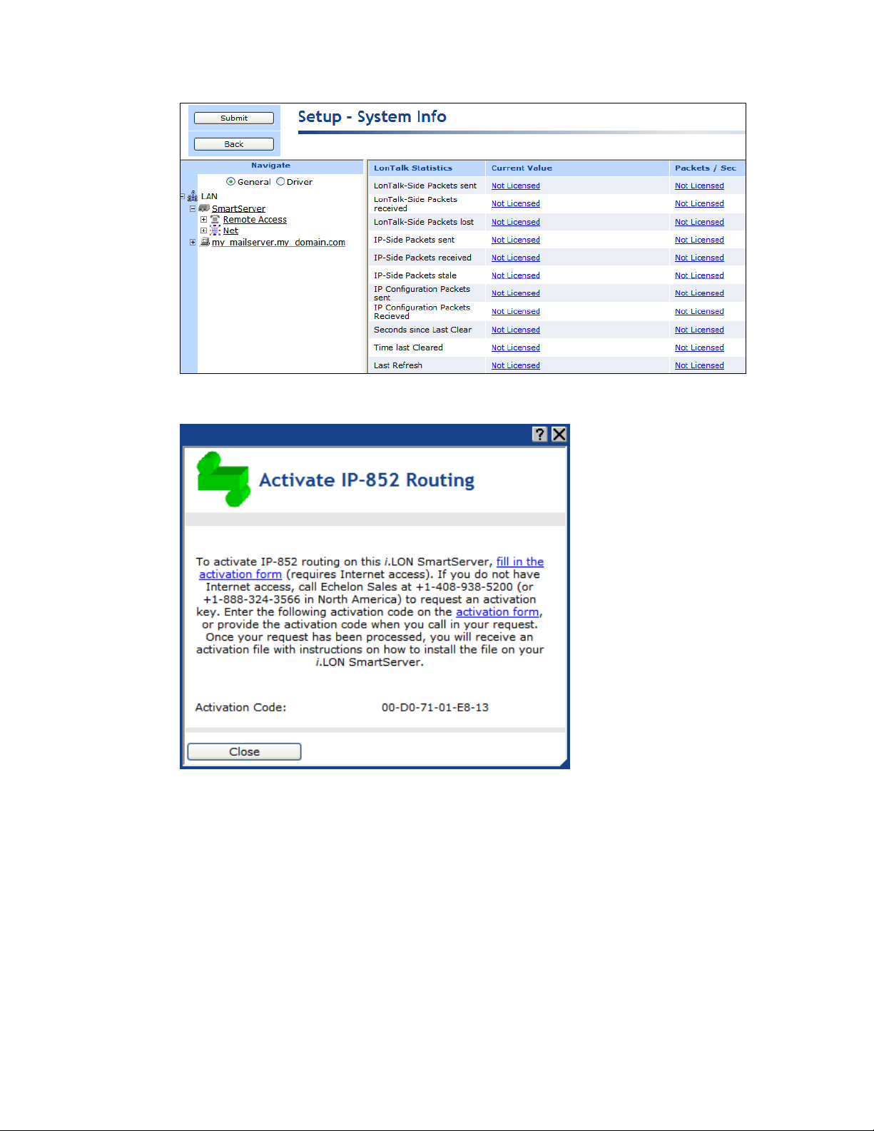
4. Click any Not Licensed link in the IP-852 router properties. The Activate IP-852 Routing dialog
opens.
5. Follow the instructions on the dialog to obtain your license and activate IP-852 routing on your
SmartServer.
6. If you do not plan on using the standard local port for IP-852 routing (1628), follow the steps in
Adding an IP-852 Configuration Server to add the IP-852 Configuration Server to the
SmartServer.
7. Add the SmartServer to a new or existing IP-852 channel with the IP-852 Configuration Server
program. For instructions on using this program to add a SmartServer to an IP-852 channel, see
the next section, Adding a SmartServer to an IP-852 Channel.
8. A LON IP channel and a router are added underneath the network icon, and the IP-852 routing
service on the SmartServer is activated.
86 Configuring and Managing the SmartServer
Page 86

Adding a SmartServer to an IP-852 Channel
You can use the IP-852 Configuration Server application to add a SmartServer to an IP-852 channel.
To do this, follow these steps:
1. Start the IP-852 Configuration Server application. Click Start on the taskbar, point to Programs,
point to Echelon IP-852 Configuration Server, and then click IP-852 Configuration Server.
The IP-852 Configuration Server main dialog opens.
2. Verify that the IP-852 Configuration Server is attached to your IP network. To do this, you
confirm that the IP network is enabled and verify the IP address of the IP-852 Configuration
Server computer is correct.
3. To confirm that the IP network is enabled, check that the Network status box displays “Enabled”.
If “Enabled” is not displayed, click Network and then select Enabled. The IP-852 Configuration
Server should correctly detect and display the IP address of your computer in the Channel
Description box.
4. To verify the IP address of the IP-852 Configuration Server computer, click Network and then
select Settings. Confirm that the IP address of the IP-852 Configuration Server computer is
shown in the Local IP Address or Hostname box.
5. If you are adding the SmartServer to a new IP-852 channel, click Channel and then click New
Channel. Configure the channel following the IP-852 Channel User’s Guide.
6. Right-click the IP-852 channel to which the SmartServer is to be added, and select New Device on
the shortcut menu. An IP-852 device is added to the channel.
7. Enter a descriptive name for the new IP-852 device.
8. Right click the new IP-852 device and select Device Properties. The New Device Properties
dialog appears with the IP Address tab selected.
9. Enter the IP address of the SmartServer in the IP Address or Hostname box and then click
Apply. This is the same IP address that you assigned to the SmartServer using the Setup Web
pages. If you enter a hostname, it must be registered with a DNS server that is available to the IP852 Configuration Server computer.
10. Click the i.LON Time Zone tab and set the time zone corresponding with the geographical area in
which the SmartServer resides and then click OK.
11. The IP-852 Configuration Server adds the SmartServer to the IP-852 channel and updates the
configuration of the SmartServer automatically.
For more information on using the IP-852 Configuration Server application, see the IP-852 Channel
User’s Guide.
Configuring the SmartServer as an IP-852 Router
You can configure your SmartServer as an IP-852 router using an OpenLNS or LNS application such
as OpenLNS CT or the SmartServer (from the OpenLNS tree using the LNS Proxy Web service). For
information on using OpenLNS CT to configure your SmartServer as an IP-852 router, see Chapter 2
of the IP-852 Channel User’s Guide.
To use the OpenLNS tree on the SmartServer to configure your SmartServer as an IP-852 router,
follow these steps:
1. Verify that EES 2.2 and OpenLNS Server have been installed on your computer. See Chapter 1 of
the Echelon Enterprise Services 2.2 User’s Guide for how to perform these installations.
2. Verify that an OpenLNS Server computer containing the OpenLNS network database in which the
SmartServer is to be used an IP-852 router has been added to the LAN. See Adding an OpenLNS
Server to the LAN in Chapter 3 for more information on how to do this.
SmartServer 2.2 User’s Guide 87
Page 87
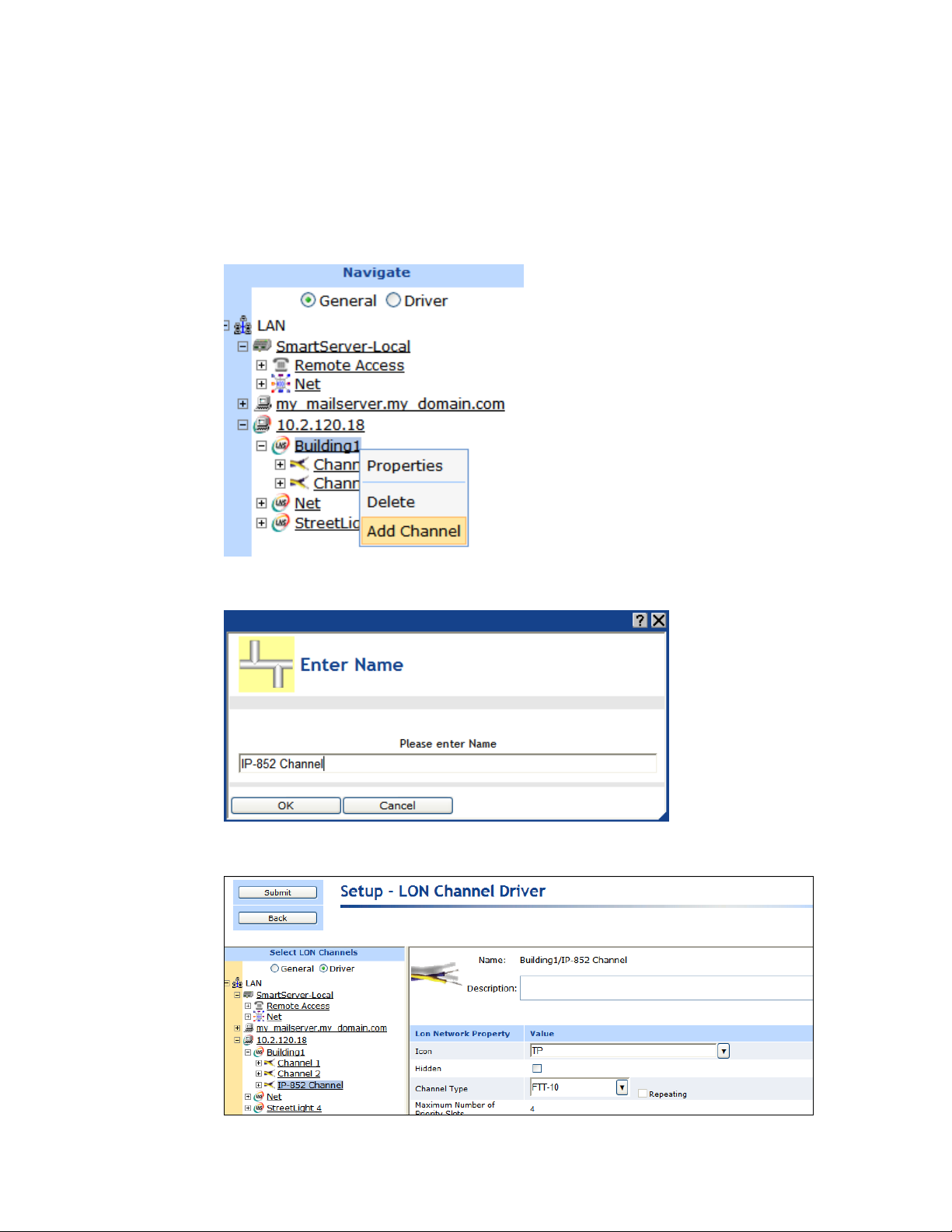
3. Expand the LNS Server icon, and then enter the User Name and Password for logging in to the
OpenLNS Server via the Echelon Enterprise Services 2.2. You initially specified the user name
and password in the Echelon Enterprise Services 2.2 installer. If you forgot the user name and
password, you can right-click the Echelon Enterprise Services 2.2 tray icon in the notification area
of your computer, and then click Options on the shortcut menu.
4. Create an IP-852 channel in the OpenLNS tree. To do this follow these steps:
a. Right-click the OpenLNS network icon and then click Add Channel on the shortcut menu.
b. The Enter Name dialog opens. Enter a descriptive name for the IP-852 channel such as
“IP-852 Channel”, click OK, and then click Submit.
c. Click the channel created in step b and then click Driver. The Setup – LON Channel
Driver Web page opens.
88 Configuring and Managing the SmartServer
Page 88

d. In the Icon property, select the IP icon; in the Channel Type property, select IP-10L (if
using a local IP network) or IP- 10W (if using a wide area IP network); and then click
Submit.
5. Add a router between the LONWORKS channel closest to the OpenLNS network interface and the
IP-852 channel. To do this follow these steps:
a. Right-click the LONWORKS channel closest to the OpenLNS network interface and then click
Add Router on the shortcut menu.
b. The Add Router dialog opens. Enter a descriptive name for the IP-852 router on the
SmartServer such as “IP-852 Router (SmartServer)”, select the IP-852 channel created in step
4 in the Target Channel property, and then click OK.
SmartServer 2.2 User’s Guide 89
Page 89

c. The Setup – LON Router Driver Web page opens, and router icons are added under the
LONWORKS channel (near side) and the IP-852 Channel (far side) in the OpenLNS tree.
d. Click Submit.
6. Commission the near side of the SmartServer’s IP-852 router. To do this, follow these steps:
a. In the Neuron ID property on the Setup – LON Router Driver Web page, click Use Service
Pin.
90 Configuring and Managing the SmartServer
Page 90

b. The LON Device Identification dialog opens. Press the service pin on your SmartServer,
click OK to return to the Setup – LON Router Driver Web page.
Service pin messages for the i.LON App (Internal) and i.LON NI (Internal) devices also
appear with the one for the Router (Internal) device if the Show Messages with Identical
Program ID Only check box is cleared. However, the Neuron ID of the IP-852 router is
selected by default because its program ID matches the one fetched from the IP-852 Router
device.
c. Click Submit.
7. Select Smart Network Management at the top of the Web page and then click Submit. This
automatically commissions the IP-852 router and starts the router application.
SmartServer 2.2 User’s Guide 91
Page 91

Alternatively, you can scroll down to the Commission Status property, and either select the
individual Smart Network Management property option to the left or select Commissioned from
the list to the right. In the Application Status property, select the individual Smart Network
Management property option to the left or select Application Online (Running) from the list to
the right. Click Submit.
8. You can repeat steps 5–6 to add and commission another i.LON IP-852 router (SmartServer,
i.LON e3 Server, or i.LON 600 IP-852 Router) between the IP-852 channel and another
LONWORKS channel. The i.LON IP-852 router to be added and commissioned must already have
been added to the IP-852 channel with the IP-852 Configuration Server application.
Note: You must add the i.LON IP-852 router to the IP-852 channel you created in step 4 and
commission the near side of the router (the router icon below the IP-852 channel).
9. After you have added and commissioned the i.LON IP-852 router, you can use the OpenLNS tree
to create LONWORKS connections between the devices attached your SmartServer and the devices
attached to the i.LON IP-852 router created in step 7. See Connecting LONWORKS Data Points
with LONWORKS Connections in Chapter 5, Using the SmartServer as a Network Management
Tool, for more information on creating LONWORKS connections.
Using an IP-852 Channel
An IP-852 channel uses the IP addresses on a shared IP network to form a “virtual wire” connecting
IP-852 devices. IP-852 devices use this virtual wire in the same way they use traditional dedicated
twisted pair wiring.
The concept of an IP-852 channel is similar to a Virtual Private Network (VPN). Each IP-852 device
in the system is aware of its peers and each IP-852 device keeps peer information in its routing tables
92 Configuring and Managing the SmartServer
Page 92

FT-10
FT-10
TCP/IP
FT-10
Flooor
One
Channel
Floor
Two
Channel
Floor
Three
Channel
SmartServer
SmartServer
SmartServer
IP-852
Configuration Server
IP-852
Channel
OpenLNS Server
Computer
so it can forward LONWORKS packets to the correct IP address. The following figure shows a typical
IP-852 channel configuration.
This example demonstrates a network in which three SmartServers are used to create an IP-852
channel connecting three TP/FT-10 channels, each of which connects the devices installed on a
different floor in a building. The circled portion of the diagram represents the IP-852 channel—the
virtual, IP-based connection between the three SmartServers, the OpenLNS Server, and the IP-852
Configuration Server. An OpenLNS, LNS, or OpenLDV application can use this IP-852 channel to
communicate with the devices on all three of the TP/FT-10 channels connected to each of the three
SmartServers, and monitor and control the entire building.
A complete installation may contain many IP-852 devices attached to one IP-852 channel. Because the
IP-852 channel can exist on any IP network, a system may now span the entire globe as easily as it
once spanned a single building, as shown in the following figure.
SmartServer 2.2 User’s Guide 93
Page 93

SmartServer
SmartServer
TCP/IP
FT-10
TP/XF-1250
SmartServer
TCP/IP
SmartServer
FT-10
SmartServer
FT-10
Building 1
New York
Building 2
London
IP-852
Channel
OpenLNS Server
Computer
FT-10 or PL-20 Channel
SmartServer
RNI
TCP/IP
Network
Building Site
Network Operation Center
OpenLNS or OpenLDV
Application
Using the SmartServer as an RNI
You can use the SmartServer as a Remote Network Interface (RNI). This enables you to connect an
OpenLNS, LNS, or OpenLDV-based application to a LONWORKS network remotely via a TCP/IP
connection. This means that you do not need to install a local network interface (for example,
PCLTA-10, PCLTA-20 and 21, PCC-10, or U10) on the computer running the OpenLNS, LNS, or
OpenLDV-based application to connect it to the LONWORKS network. The following figure
demonstrates how the SmartServer can be used as an RNI to connect a computer running an OpenLNS,
LNS, or OpenLDV-based application to a LONWORKS network.
To use the SmartServer as an RNI, you must configure the RNI settings for the SmartServer on the
computer running the OpenLNS, LNS, or OpenLDV-based application with the LONWORKS Interfaces
application. Once you have done this, the SmartServer will appear in the list of available network
interfaces you can use with your OpenLNS and OpenLDV-based applications.
Note: If you are using either LNS or OpenLDV, you need to install OpenLDV 4.0 on your computer to
create the remote network connection. You can download OpenLDV 4.0 from the Echelon support
Web site at www.echelon.com/support. OpenLDV 4.0 is included with OpenLNS.
This section describes the following:
How to configure your SmartServer as an RNI using the LONWORKS Interfaces application.
How to configure the RNI properties on the SmartServer.
Limits on the SmartServer when operating as an RNI.
How to switch the network interface to an RNI or a local network interface.
Differences between using an RNI and IP-852 routing to connect an OpenLNS, LNS, and
OpenLDV-based application to a LONWORKS network.
94 Configuring and Managing the SmartServer
Page 94

Name
Enter a unique name for the RNI to be configured on the SmartServer.
This will be used as a lookup key to access the proper registry entry each
time xDriver initiates a connection to this RNI.
The name you specify will be appended to the name of the RNI's xDriver
Configuring the SmartServer as a Remote Network Interface
You can use the LONWORKS Interfaces Control Panel application to configure your SmartServer as an
RNI. You can then reference this RNI with your OpenLNS, LNS, or OpenLDV-based application to
connect the application to the LONWORKS network attached to the SmartServer. A separate entry is
required for each SmartServer you plan to use as an RNI and connect to the OpenLNS or LNS Server.
If you are managing a large application on a single OpenLNS or LNS workstation and will be using
many SmartServers (more than 50), you can create an external lookup extension to improve
performance. See the OpenLDV Programmer’s Guide, xDriver Supplement for more information on
doing this.
To use the LONWORKS Interfaces application to configure your SmartServer as an RNI, follow these
steps:
1. Click Start on the taskbar, open the Control Panel, and then double-click the LONWORKS
Interfaces application. The LONWORKS Interfaces application’s opens and the RNI tab is
selected.
2. Click Interface, point to Add, and then either click RNI Interface or click New Interface and
then click RNI in the Select Interface Type dialog.
3. The Add Network Interface Wizard dialog opens.
4. Enter the following properties for the RNI:
SmartServer 2.2 User’s Guide 95
Page 95

profile (for example, "X.Default" is the name of the default profile). If you
enter "myRNI" for example, the name of your RNI by default will be
"X.Default.myRNI".
Optionally, select the xDriver profile to be used by your RNI. Typically,
you will use the Default Profile; however, you can select a different
profile. An xDriver profile represents a set of configuration parameters
that determine how xDriver manages a group of connections. The profile
that xDriver uses for each connection is determined on a
session-by-session basis.
IP Address/
Hostname
Specifies the hostname or IP address of the RNI. This is the same IP
address that you assigned to the SmartServer using the Setup Web pages.
If you enter a hostname, it must be registered with a DNS server that is
available to the computer on which the LONWORKS Interfaces application
is running
You may enter a hostname (for example, myilon.mynet.com), IPv4
address (for example, 192.168.1.1), or IPv6 address (for example,
FEDC:BA98:7654:3210:0123:4567:89AB:CDEF). You may enter any
valid IPv6 notation in addition to the preferred form shown above.
If you enter an IPv6 address, the address you enter must conform to the
IPv6 addressing standards. The following provides two example IPv6
addresses:
2002:1234:0000:0000:02d0:71ff:fe00:00aa
2002:1234::2d0:71ff:fe00:aa
For more information about IPv6 addressing, see "RFC 3513 - Internet
Protocol Version 6 (IPv6) Addressing Architecture" at
www.faqs.org/rfcs/rfc3513.html. Section 2.2 of the RFC describes the
addressing formats shown above in more detail.
In the Port box, enter the port number on which the SmartServer should
listen for messages when it is used as an RNI. The default port is 1628.
Authentication
Specify how connections between the SmartServer RNI and the OpenLNS
Server are authenticated. Using authentication prevents the RNI or
OpenLNS Server from responding to unauthorized messages during an
xDriver session. You have the following two choices:
Use MD5 Key. Enter a 32-character hexadecimal string representing
a 128-bit MD5 key. The 32 characters must be entered in
colon-separated pairs. For example:
A9:04:87:49:F4:BF:89:59:03:10:C5:47:BD:45:94:D7.
This key must match the MD5 authentication key configured into the
device. Setting the authentication key to all 0s causes xDriver to use
the pre-defined, default factory authentication key for the
SmartServer RNI device. For security reasons, do not use the default
authentication key. This is the default authentication type.
Use Secret Phrase. Enter a 16 to 63 character string that matches the
text secret phrase configured into the SmartServer RNI device.
96 Configuring and Managing the SmartServer
Page 96

5. Click OK to create the RNI.
6. The SmartServer is now configured as an RNI. The name you entered for the SmartServer RNI
device appears in the list view on the left side of the user interface.
7. Optionally, you can continue configuring the RNI by editing the properties on the right side of the
user interface. See the LONWORKS Interfaces on-line help for more information on configuring
the RNI.
SmartServer 2.2 User’s Guide 97
Page 97

8. Using the SmartServer Web interface, verify that the SmartServer is enabled for RNI connections.
Right-click the SmartServer host device, point to Setup, and then click Security. The Security
Web page opens. In the Service section, confirm that the Enable Downlink RNI Connections
check box is selected.
9. You can now use the RNI configured on your SmartServer to connect an OpenLNS, LNS, or
OpenLDV application to a LONWORKS network, just as you would with any other local
LONWORKS network interface.
Note: You may have multiple SmartServers configured as RNIs that are all connected to the same
channel. This is a valid configuration; however, if your OpenLNS, LNS, or OpenLDV application
uses the RNI on any of those SmartServer to connect to the channel, the application cannot
commission any of the other SmartServers that are also configured to operate as RNIs. This is because
the SmartServer being commissioned would be assigned the same network address as the SmartServer
used to access the channel. To avoid this, either program your application to assign the SmartServer
being commissioned a different network address, or you disable the RNI on the SmartServer being
commissioned. You can disable the RNI by clearing the Enable Downlink RNI Connections option
in the Service section of the Security Web page.
Configuring the SmartServer RNI Properties
You can configure the SmartServer’s RNI properties using the SmartServer Web pages following these
steps.
1. Click Driver at the top of the tree.
2. Expand the network icon, expand the SmartServer’s internal LON channel, and then click the RNI
(Internal) device. The Setup – LON RNI Driver Web page opens.
98 Configuring and Managing the SmartServer
Page 98

Port
Displays the port used by the SmartServer to listen for LonTalk packets
when it is being used as an RNI. The default port is 1628.
3. Scroll to the RNI Property header and configure the following properties:
SmartServer 2.2 User’s Guide 99
Page 99

Maximum Number
of Simultaneous
Receive
Transactions
Enter the maximum number of receive transactions that the RNI
application can receive at one time. This value may range from 1 to
32,768. The default value is 16. You can increase this value if you
observe buffer overflows. You can decrease this value if you observe that
the SmartServer’s memory is low.
A receive transaction entry is required for any incoming message which
uses either repeating or acknowledged messaging service (a receive
transaction is not required for messages using unacknowledged service).
A receive transaction entry is also required for each unique source
address/destination address/priority attribute.
Each receive transaction entry contains a current transaction number. A
message is considered to be a duplicate if its source address, destination
address, and priority attribute vector into an existing receive transaction
and the message’s transaction number matches the entry’s transaction
number.
Receive transaction entries are freed after the receive timer expires. The
receive timer duration is determined by the destination device and varies
as a function of the message addressing mode. For group addressed
messages, the receive timer is determined by the address table. For
Neuron ID addressed messages, the receive timer is fixed at eight seconds.
For other addressing modes, the non-group receive timer in the
configuration data structure is used.
4. Click Submit to save your changes.
SmartServer RNI Limits
The capabilities of the RNI on the SmartServer depend largely on the software running on the host
computer. When configured as an RNI, the SmartServer has the following limits:
Up to 32,768 address table entries.
Up to 256 simultaneous outgoing transactions.
Up to 32,768 simultaneous incoming trasactions.
Up to 1,024 network variable aliases.
Up to 256 groups, with up to 15 used for incoming messages.
Up to 4,096 dynamic network variables.
Output messages can be sent to up to 256 different destination addresses within each 24-second
interval. Multiple messages can be sent to each of those destination addresses within the interval.
One RNI link at a time.
See Introduction to LONWORKS Platform for more information about these limits. This guide is
available on the Echelon Web site at www.echelon.com/docs.
Switching Between the SmartServer RNI and a Local Network Interface
You can switch the network interface used by an OpenLNS, LNS, or OpenLDV application to
communicate with a LONWORKS network. You can switch to either the RNI configured on the
SmartServer or a local network interface such as a PCLTA-20 or 21, PCLTA-10, PCC-10, or U-10.
If your SmartServer is configured as an RNI and want to switch to a local LONWORKS network
interface, but you want to leave the SmartServer attached to the network, you must disable the RNI
100 Configuring and Managing the SmartServer
Page 100

application on the SmartServer before opening the network with the new network interface. You can
disable the RNI using the SmartServer Web interface or the console application.
To use the SmartServer Web interface to disable the RNI, right-click the SmartServer host device,
point to Setup, and then click Security. The Setup – Security Web page opens. In the Service
section, clear the Enable Downlink RNI Connections check box. To restart the RNI application
later, select the Enable Downlink RNI Connections check box.
To use the console application to disable the RNI, enter the following command:
deactivate 4
“4” is the index of the RNI application. You can obtain the index of the applications on the
SmartServer by entering the following command:
listapp
Confirm that you want to disable the RNI application. Disabling the RNI application may cause
the SmartServer to reboot. To restart the RNI application later, enter the following command:
activate 4
See Appendix B for more information about the console application.
If you are using a local LONWORKS network interface and you want to switch the network interface to
the RNI configured on the SmartServer, you must physically remove the local network interface device
from the network.
Connecting the SmartServer with RNI vs. IP-852
You can use the SmartServer to connect an OpenLNS, LNS, and OpenLDV-based application to a
LONWORKS network over an IP network. You can create this remote connection by either configuring
the SmartServer as an RNI or activating IP-852 routing on the SmartServer and adding it to the same
IP-852 channel on which the computer running the OpenLNS, LNS, or OpenLDV application resides.
If you use the SmartServer as an RNI, it means that you are using it as a network interface to establish
a point-to-point connection between an OpenLNS, LNS, or OpenLDV-based application and the
LONWORKS channel to which your SmartServer is attached. This approach is simpler than using
IP-852 routing and is an option if you are only using a single SmartServer on one channel.
If you need to connect multiple TP/FT-10 or PL-20 channels over an IP network so that a single
application could connect to the devices on each channel, then you can use IP-852 routing on the
SmartServer. In addition, you can use IP-852 routing if you have multiple SmartServers on multiple
channels, and you want to connect the channels. This may be especially useful if each SmartServer
needs to connect to the same OpenLNS or LNS Server.
In addition, you can use a SmartServer as an RNI and as an IP-852 router simultaneously. For
example, consider a building with multiple floors, where the devices in the rooms on each floor are
connected by an FT-10 channel, and each floor has a SmartServer installed to manage those devices.
You could create an IP-852 channel to connect all three floors and control them with a central
application. This would be the best way to perform control of the building over a long period of time.
However, you may need another entry point into the network at some point, to perform maintenance on
a certain part of the building. In this case, you could configure the SmartServer as an RNI for a
specific floor to be accessed by an OpenLNS, LNS, or OpenLDV application. This would prevent you
from having to re-configure the IP-852 channel with the Configuration Server, which you may want to
avoid doing if you do not plan on making the new entry point a long-term part of the network.
The following figure demonstrates a SmartServer on an IP-852 channel being configured as an RNI for
a specific floor (Floor 3) of a building. This enabled an OpenLNS, LNS, or OpenLDV application to
connect to the devices on Floor 3 without having to re-configure the IP-852 channel with the
Configuration Server. In this example, the SmartServer for Floor 3 is involved in two separate TCP/IP
connections: (1) the IP-852 connection with the other SmartServers, and (2) the RNI connection with
the application for Floor 3.
SmartServer 2.2 User’s Guide 101
 Loading...