

Page 1

SLTA-10 Adapter
User’s Guide
Revision 1
®
C o r p o r a t i o n
078-0160-01B
Page 2

Echelon,
LON, LONW
ORKS
, LONM
ARK
, Neuron, 3120, 3150, LonBuilder, NodeBuilder,
LonTalk, and LonManager are trademarks of Echelon Corporation registered in the United
States and other countries. LonMaker and LonSupport are trademarks of Echelon.
Other brand and product names may be trademarks or registered trademarks of their
respective companies.
Neuron Chips, Serial LonTalk Adapters, and other OEM products were not designed for
use in equipment or systems which involve danger to human health or safety or a risk of
property damage, and Echelon assumes no responsibility or liability for use of the Neuron
Chips or Power Line products in such applications.
Parts manufactured by vendors other than Echelon and referenced in this document have
been described for illustrative purposes only and may not have been tested by Echelon. It
is the responsibility of the customer to determine the suitability of these parts for each
application.
ECHELON MAKES AND YOU RECEIVE NO WARRANTIES OR CONDITIONS,
EXPRESS, IMPLIED, STATUTORY OR IN ANY COMMUNICATION WITH YOU, AND
ECHELON SPECIFICALLY DISCLAIMS ANY IMPLIED WARRANTY OF
MERCHANTABILITY OR FITNESS FOR A PARTICULAR PURPOSE.
No part of this publication may be reproduced, stored in a retrieval system, or transmitted,
in any form or by any means, electronic, mechanical, photocopying, recording, or otherwise,
without the prior written permission of Echelon Corporation.
Printed in the United States of America.
Copyright ©1996 - 1997 by Echelon Corporation.
Echelon Corporation
4015 Miranda Avenue
Palo Alto, CA 94304, USA
SLTA-10 Adapter User’s Guide 2
Page 3

Preface
This document describes how to use the SLTA-10 Serial LonTalk® Adapter to
connect a host processor, with an EIA-232 (formerly RS-232) serial interface,
to a LONW
ORKS
®
network.
SLTA-10 Adapter User’s Guide 3
Page 4

Content
This manual provides detailed information about the hardware and software for the SLTA-10
Adapter.
• Chapter 1 introduces the SLTA-10 Adapter and provides a quick overview.
• Chapter 2 describes the SLTA-10 Adapter hardware.
• Chapter 3 describes how to attach an SLTA-10 Adapter.
• Chapter 4 describes the configuration switches of the SLTA-10 Adapter.
• Chapter 5 describes the software for the SLTA-10 NSI mode.
• Chapter 6 describes the software for the SLTA-10 MIP mode.
• Chapter 7 discusses using the Windows
software with the SLTA-10 NSI mode.
• Chapter 8 discusses using the DOS network driver with the SLTA-10 MIP mode.
• Chapter 9 discusses creating an SLTA-10 MIP mode network driver for any host.
• Chapter 10 describes initilization and installing as a node.
• Chapter 11 discusses using an SLTA-10 Adapter with a modem.
• Chapter 12 describes the DOS Host Connect Utility (HCU) for use with the SLTA-10 MIP
mode.
• Chapter 13 is a troubleshooting section.
• Appendix A describes the Windows 3.1x DLL files for use with the SLTA-10 Adapter.
®
NTTM network driver and the SLTALink Manager
SLTA-10 Adapter User’s Guide 4
Page 5

Related Manuals
The following Echelon documents are suggested reading for more information:
•The
A
LC
Object and Data Server Programmer’s Guide
describes how to write a 32-bit Windows
host application and installation tool that can be used with the SLTA-10 NSI mode.
•The
ONWORKS
L
Host Application Programmer’s Guide
describes how to write a host
application that can be used with the SLTA-10 MIP mode.
•The
LonBuilder
®
User’s Guide
describes how to develop L
ONWORKS
applications with the
LonBuilder Developer's Workbench.
•The
NodeBuilder
™
User’s Guide
describes how to develop L
ONWORKS
applications with the
NodeBuilder Development Tool.
• Both Motorola and Toshiba have authored Neuron
®
Chip databooks containing specifications
and literature that describe the architecture of the Neuron Chip.
Web Access
Engineering bulletins and data sheets supporting this product are available on the Echelon Web
site. General information regarding Echelon, its business, and its products also are located on the
site at http://www. echelon.com.
SLTA-10 Adapter User’s Guide 5
Page 6

SLTA-10 Adapter User’s Guide 6
Page 7

Contents
Preface
Content 4
Related Manuals 5
Web Access 5
1 SLTA-10 Adapter Overview 11
Introduction 12
Two Modes of Operation: SLTA-10 NSI and MIP Modes 13
SLTA-10 NSI Mode Features 14
SLTA-10 MIP Mode Versus the SLTA/2 14
The SLTA-10 Adapter Configurations 14
Software Availability 14
LNS 1.0, 1.01, and 1.5 Compatibility 15
TAPI Compatibility 16
2 SLTA-10 Adapter Hardware 17
Mechanical Description 18
Switches, Indicators, and Connectors 20
ESD Warning 20
Connecting Power 22
3 Cabling and Connections 25
Attaching the SLTA-10 Adapter 26
Attaching the SLTA-10 Adapter to a PC 26
Attaching the SLTA-10 Adapter to a Modem 27
Attaching the SLTA-10 Adapter to a Network 28
4 Hardware Configuration 29
Configuring the SLTA-10 Adapter Hardware 30
Configuration Options 30
Interface Link Protocol Control (Switch1 / CFG3) 30
Modem Support (Switch2 / CFG2) 31
Network Disable (Switch3 / CFG1) 32
Serial Network Services Interface (Switch4 / NSI) 33
Autobaud (AB) 34
Serial Bit Rate (Switches[6..8] / Baud[2..0]) 34
Configuring the SLTA-10 Adapter Software 36
5The SLTA-10 NSI Mode Software 39
SLTA-10 NSI Mode Software Overview 40
Windows NT Software Installation Procedure 40
Windows NT Software Installation Results 41
SLTA-10 Adapter User’s Guide 7
Page 8

6The SLTA-10 MIP Mode Software 43
SLTA-10 MIP Mode Software Overview 44
Installing the SLTA-10 MIP Mode Adapter Software 44
Installing the Windows 3.1x DLL Software 47
Other Drivers 48
7Using the Windows NT Driver and SLTALink Manager with SLTA-10 NSI Mode
Software Overview 50
Establishing a Communications Line for Dialing in to a Network 51
Establishing a Communication Line for Calls Dialed out to the PC 53
Establishing Remote and Local Network Sites 54
Name of Link 55
Remote Identifier 55
Link Type 55
Configuring the Modem Line 55
SLTA Password 56
Invoking an Application 56
Enabling a Callback 56
Diagnostics 57
The SLTALink Manager Programmatic Interface 57
Using the DOS "Stub" Driver 58
Characteristics of a Well-Designed System 58
Call Initiation 58
Dial-In to the Network Only 58
Dial-Out to the Remote PC Only 59
Dial-In / Dial-Out 59
Callback 60
Call Termination 60
Monitoring: Application Termination Strategy 61
Monitoring: Missing Messages after a Dial-Out 61
Monitoring: LNS Application Design Issues 62
Good Practices / Schemes that Work 62
49
8 Using the DOS Driver with SLTA-10 MIP Mode 67
Installing the SLTA-10 Mip Mode Driver for DOS 68
Buffer Options 68
Serial Bit Rate Options 69
DOS Device Options 69
Timing Options 70
Network Interface Protocol Options 71
Calling the Network Driver from a Host Application 73
Using the SLTA-10 Adapter Driver under Microsoft Windows 3.1x 75
SLTA-10 Adapter User’s Guide 8
Page 9

9 Creating an SLTA-10 MIP Mode Driver 77
Purpose of the Network Driver 78
Example Network Drivers 78
Implementing an SLTA-10 MIP Mode Network Driver 78
Network Interface Protocol 81
Link Layer Protocol 81
ALERT/ACK Link Protocol 81
Buffered Link Protocol 83
Transport Layer Protocol 84
SLTA-10 Adapter Timing Data 85
Downlink Byte-to-Byte Receive Timeout 85
Uplink Message Life 86
ACK/NACK Receive Timeout 86
Uplink Timeout Message Retry Count 86
Session Layer Protocol 86
Downlink Buffer Request Protocol 86
Uplink Flow Control Pr otocol 88
Presentation Layer Protocol 89
10 Initialization and Installation
Initializing an SLTA-10 Adapter 92
Installing an SLTA-10 Adapter on a Network 93
Installing with LNS 93
Installing with the LonBuilder or NodeBuilder Tools 93
Installing an SLTA-10 Adapter with LonManager API, the DOS-based
LonMamager LonMaker Installation Tool, or DDE Server 94
11 Using the SLTA-10 Adapter with a Modem 95
Overview 96
SLTA-10 Adapter Connection States 97
Command Set Assumptions 98
Translated Characters 98
DTE Connections 98
Network Management Messages 99
EEPROM String Pool Management 101
Product Query 103
Send Modem String 103
Modem Response Query 104
Connection Status Query 104
Install Directory Entry 105
Dial From Directory 105
Hang-up 106
Install Password 106
Install Modem Configuration String 107
Install Hangup String (MIP mode only) 107
Install Dial Prefix 108
Install Hangup Timer 108
Configure Modem 108
Request /Release SLTA 109
91
SLTA-10 Adapter User’s Guide 9
Page 10

Clear EEPROM Pool 109
Install NVConnect (NSI mode only) 109
Install NSIConnect (NSI mode only) 110
Install CallbackEnable (NSI mode only) 110
Report SLTAEE (NSI mode only) 110
Modem Compatibility 111
12 Using the DOS Host Connect Utility with the SLTA-10 MIP Mode 113
HCU Usage 114
Theory of Operation 115
Usage Examples 116
Suggested Modem Configurations 116
Status and Error Reporting 117
13 Modem Troubleshooting 119
Troubleshooting a Modem Link 120
SLTA-10 Adapter and Modem Do Not Answer or Pick Up 120
Modems Will Not Connect 120
SLTA-10 Adapter to Host Link Fails Completely 120
SLTA-10 Adapter to Host Link Fails Partially 121
SLTA-10 Adapter Sends Modem Configuration String,
But It Has No Effect 121
Appendix A — Windows DLL 123
ldv_close 124
ldv_get_version 125
ldv_open 126
ldv_read 127
ldv_write 128
SLTA-10 Adapter User’s Guide 10
Page 11

Chapter 1
SLTA-10 Adapter Overview
The SLTA-10 Serial LonTalk Adapter (Models 73351, 73352, and 73353)
is a network interface that enables any host processor with an EIA-232
serial interface to connect to a LONW
Adapter extends the reach of LONW
hosts, including desktop, laptop, and palmtop PCs, workstations,
embedded microprocessors, and microcontrollers.
The SLTA-10 Adapter has two modes of operation: NSI and MIP modes.
The SLTA-10 NSI mode is compatible with LNS-based applications.
The SLTA-10 MIP mode is compatible with legacy applications based on
the LonManager® API or the HA host application software. The SLTA-
10 MIP mode is a replacement for the SLTA/2 Serial LonTalk Adapter.
An externally accessible DIP switch determines the mode of operation.
ORKS
network. The SLTA-10
ORKS
technology to a variety of
SLTA-10 Adapter User’s Guide 11
Page 12

Introduction
The SLTA-10 Adapter is the latest addition to the SLTA product family. It is an EIA-232
(formerly RS-232) compatible serial device that allows any host with an EIA-232 interface and
proper software to communicate with a L
ONWORKS
network.
An SLTA-10 Adapter enables the attached host to act as an application node on a L
network. When used with a PC host and the LNS Developer’s Kit for Windows software, the
SLTA-10 Adapter can be used to build sophisticated network management, monitoring, and
control tools for L
applications such as the LonManager LonMaker installation tool, LonManager DDE Server, or
applications based on the LonManager API.
An SLTA-10 Adapter can be connected to the host through a pair of modems and the telephone
network, allowing the monitoring, control, or network management computers to be remote from
the network. The SLTA-10 Adapter can be set up to answer incoming calls from a remote host. In
addition, any node on the local network can initiate a telephone call to a remote host computer. A
new feature, available only in the SLTA-10 NSI mode (see below), allows the SLTA-10 Adapter
itself to initiate a phone call to a remote host computer.
Figure 1 illustrates a typical node based on an SLTA-10 Adapter. Chapter 11,
Adapter with a Modem
network.
ONWORKS
networks. The SLTA-10 adapter also can be used with legacy host
, shows an SLTA-10 Adapter connected to a host through the telephone
ONWORKS
Using the SLTA-10
Host
Host Application
LNS or LonManager
Software (optional)
Driver
Interface
Network Driver
EIA-232
Interface
Network
Interface
SLTA-10
Network Adapter
Transceiver
Interface
LONW
ORKS
Network
Figure 1 SLTA-10 Adapter Node Architecture with Local Host
SLTA-10 Adapter User’s Guide 12
Page 13

Two Modes of Operation: SLTA-10 NSI and MIP Modes
The SLTA-10 Adapter provides both the network services interface (NSI mode) functionality for
use with LNS-compliant applications, and network interface functionality (MIP mode) for use with
LonManager API-based applications.
There are two separate firmware images in the SLTA-10 Adapter. The two separate images have
different link layer protocols, different network drivers, different buffer capacity, and different
functionality. The two modes of operation are the SLTA-10 NSI mode and the SLTA-10 MIP
mode. The mode of operation is controlled by an externally accessible DIP switch at power-up.
Table 1 illustrates the differences between the SLTA-10 NSI mode, the SLTA-10 MIP mode, and
the SLTA/2.
Table 1 SLTA-10 NSI and MIP Modes and SLTA/2 Feature Comparison
Feature SLTA-10
NSI Mode
Supports LNS applications YES NO NO
Supports LonManager API
applications
Available drivers Windows NT
Software used to establish
connections via modems
Who initiates calls from a remote
network
Input power options 9-30VAC or DC
Configuration Switches Externally
Network Connector Color coded,
Processor Input Clock 10 MHz 10 MHz 5 MHz (10MHZ for
Ready to wall mount YES YES Bracket Required
Transceiver versions available TP/FT-10
To attach to a modem Special null
Supports sleep mode NO NO YES
Message Tag 15 available NO YES YES
Default Buffer Configuration See Chapter 4 See Chapter 4 See SLTA/2
YES YES YES
(Windows 95
planned)
SLTALink Manager
(TAPI application)
SLTA-10 itself
or “Helper / Dialer ”
node
or wall mount
supply
accessible
removable screw
terminals
(Weidmuller)
TP/XF-78
TP/XF-1250
modem cable
SLTA-10
MIP Mode
DOS, UNIX,
Windows 3.1x
HCU (DOS
application with
source code)
“Helper / Dialer ”
node on network
9-30VAC or DC
or wall mount
supply
Externally
accessible
Color coded,
removable screw
terminals
(Weidmuller)
TP/FT-10
TP/XF-78
TP/XF-1250
Special null
modem cable
SLTA/2
DOS, UNIX,
Windows 3.1x
HCU (DOS
application with
source code)
“Helper / Dialer ”
node on network
wall mount supply
or internal battery
Internally accessible
RJ45
TP/XF-1250)
TP/FT-10
TP/XF-78
TP/XF-1250
TP/RS485
Internal jumper
change to become
DTE
documentation
SLTA-10 Adapter User’s Guide 13
Page 14

SLTA-10 NSI Mode Features
The most important new feature of the SLTA-10 NSI mode is the NSI functionality for use with
LNS-compliant applications. Other important features available only in the SLTA-10 NSI mode
include: SLTA-10 initiated dial-out, a Windows NT driver, a high performance link layer protocol,
and the SLTALink Manager software. These features are not available in SLTA-10 MIP mode.
The improved hardware form factor applies to both modes of operation and is listed in Table 1.
In SLTA-10 NSI mode, an SLTA-10 Adapter supports applications based on both the LNS software
and the LonManager API.
SLTA-10 MIP Mode Versus the SLTA/2
In SLTA-10 MIP mode, the SLTA-10 Adapter is a replacement for the SLTA/2 Serial LonTalk
Adapter, with an improved form factor. The network connector on the SLTA-10 Adapter is the
color-coded removable screw terminal (Weidmuller), instead of the RJ45 used on the SLTA/2
Adapter. The SLTA-10 Adapter input power options include 9-30VAC or DC, or a 9V wall mount
supply. The SLTA-10 Adapter operates at 10MHz for all transceiver types; the SLTA/2 operates at
5MHz or 10MHz, depending on transceiver type. In addition, the SLTA-10 configuration DIP
switches are externally accessible. The SLTA-10 enclosure has been improved to allow wall
mounting, without requiring a bracket.
The SLTA/2 and the SLTA-10 MIP mode use the same drivers and li nk layer protocol.
The SLTA-10 Adapter Configurations
The SLTA-10 Adapter is available with the following transceiver and power supply options:
Transceivers
•
TP/FT-10, TP/XF-78, and TP/XF-1250. The FTT-10A (78kbps, free or bus topology), TPT/XF-78
(78kbps, bus topology) and TPT/XF-1250 (1.25Mbps, bus topology) transceivers all use
transformer-isolated, differential transmission.
Power supply
•
(Model 78030), continental European (Model 78020), and Japanese (Model 78030)
configurations. Plug-in power supplies are sold separately. Alternately, screw terminals are
supplied for use with a 9 to 30VAC/DC power sources.
. The SLTA-10 Adapter is available with three L
. 9V plug-in power supplies are available in U.S./Canada (Model 78010), U.K.
ONWORKS
channel options:
Software Availability
The SLTA-10 Adapter is not shipped with software.
Software for the SLTA-10 NSI mode is available on the LNS Developer’s Kit for Windows CD
(version 1.5 and higher), in the Connectivity Starter Kit (Model 58030-01), or from the Developer’s
Toolbox of the Echelon web site (www.echel on.com).
Software for the SLTA-10 MIP mode is distributed in the Connectivity Starter Kit (Model 58030-
01) and from the Developer’s Toolbox of the Echelon web site.
SLTA-10 Adapter User’s Guide 14
Page 15

LNS 1.0, 1.01, and 1.5 Compatibility
When the SLTA-10 Adapter is connected directly to the PC host (i.e., no modems), the SLTA-10
Adapter uses a direct connection. For a direct connection, the SLTA-10 Adapter behaves like any
other NSI, such as the PCLTA-10 Adapter or the PCC-10 PC Card. In this case, an SLTA-10
Adapter may be used without issue with applications based on LNS 1.0, 1.01, or 1.50.
The SLTA-10 Adapter is also designed so that a PC host can be connected to the network through
a pair of modems and the telephone network. In this scenario, the PC is a remote host. When the
PC initiates the phone call to the SLTA-10 Adapter, the remote host is said to “dial-in to the
network”. When the SLTA-10 Adapter initiates a call to the PC, the SLTA-10 is said to “dial-out to
the remote host”. Once the phone connection is established, the application running on the remote
host can perform network management, monitoring, or control activities.
Applications based on LNS 1.0 or 1.01 do not have full functionality with respect to the SLTA-10
Adapter and modems because LNS 1.0 and 1.01 have default system behavior that is incompatible
with using the SLTA-10 Adapter through modems. For instance, an application based on LNS 1.0
and 1.01 terminates (i.e., shuts down) in a manner that interferes with one the automatic dial-out
initiation techniques. In LNS 1.0 or 1.01 when an LNS host application is terminated, all host
network variables and connections to these variables are removed from the LNS database. One
way the SLTA-10 Adapter can initiate a phone call, or automatically dial-out, is based on a
network variable update being sent to the SLTA-10 Adapter. Since the termination of the
application on the PC host results in the removal of all network variable connections to the host,
no network variable update can be sent to the SLTA-10 Adapter. Thus, one of the two
mechanisms that support automatic dial-out is unavailable.
LNS 1.0 and 1.01 have no special knowledge of whether the SLTA-10 Adapter is remotely
connected through a pair of modems. However, LNS 1.5 automatically detects that the SLTA-10
Adapter is remote at commissioning. Using a remote SLTA-10 Adapter affects the default system
behavior by allowing the system to function as desired. Upon termination of an application based
LNS 1.5, the LNS host API will determine if the NSI uses modems and if there are any explicitly
bound network variables on the host. If both of these conditions are met, LNS does not remove the
connections or host network variables. In addition, LNS leaves the SLTA-10 Adapter configured.
Thus, LNS 1.5 fully supports the SLTA-10 Adapter accessed through a modem configuration.
In summary, LNS 1.5 fully supports using the SLTA-10 Adapter with modems. LNS 1.0 and 1.01
do not support the use of the SLTA-10 with modems, although direct connect interfaces are
supported.
Note: A remote (via modems) LNS Server requires a dedicated SLTA-10 Adapter.
Thus, some networks may require multiple SLTA-10 Adapters —one for the
remote LNS Server and others to allow access for other PCs.
SLTA-10 Adapter User’s Guide 15
Page 16

TAPI Compatibility
The SLTALink Manager software uses TAPI release 1.3 or higher. This is supported in Windows
NT 4.0, but not in Windows NT 3.51. Thus, Windows NT 3.51 does not support the use of the
SLTA-10 Adapter with modems, however, Windows NT 3.51 does support a direct connect
interface.
SLTA-10 Adapter User’s Guide 16
Page 17

Chapter 2
SLTA-10 Adapter Hardware
This chapter provides a physical description of the SLTA-10 Adapter.
SLTA-10 Adapter User’s Guide 17
Page 18

Mechanical Description
Figures 2 and 3 show the SLTA-10 Adapter in its enclosure. Figure 4 shows the SLTA-10 Adapter
board without an enclosure.
Figure 2 SLTA-10 Adapter Enclosure
SLTA-10 Adapter User’s Guide 18
Page 19
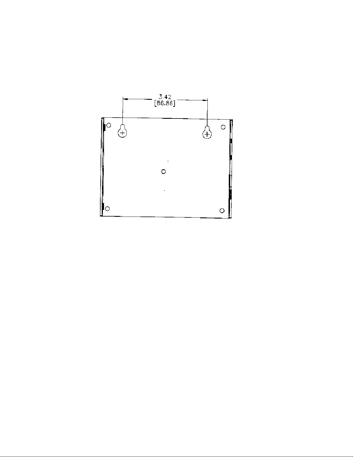
Figure 3 shows a 1:1 view of the enclosure and may be used as a mounting template.
Figure 3 SLTA-10 Adapter Enclosure Keyhole View Mounting Slots
SLTA-10 Adapter User’s Guide 19
Page 20

(S2)
Service
Button
(DS1)
Service
LED
(S1 )
Config.
Switch
Block
Component Side View
®
Neuron
3150
Chip
®
Transceiver
Section
(J5)
EIA-232
Data Port
(DS2)
Power Indicator
LED
(J3)
Power Input
(J1)
Network
Connector
SLTA-1Ø © ECHELON 1996
Figure 4 SLTA-10 Adapter Without Enclosure (Component-Side View from Top).
Switches, Indicators, and Connectors
This product contains components which are sensitive to static
electricity. Before installing or removing the network or serial
cables, touch earth ground with your hand to discharge any static
electricity which may have accumulated.
!
ESD Warning
(J2)
Power Input
SLTA-10 Adapter User’s Guide 20
Page 21

Table 2 describes the external connections and switches/LEDs on the SLTA-10 Adapter.
Table 2 SLTA-10 Adapter Interfaces
Interface Function
Service Button S2 Pressing this switch grounds the service
request pin on the Neuron Chip within the
SLTA-10 Adapter. While this switch is
pressed, the service LED should light to
maximum intensity.
If Switch 3 (the Network Disable switch) on
the switch block (S1) is in the ON/up position
the service LED will light, but
message will be sent
before an application has configured the
SLTA-10 Adapter).
(if after power up but
no service
Service LED
DS1
EIA-232 Data Port
J5
Network Connector
Two-Position
J1
(Yellow LED) Indicates that either the
Service Button is being
pressed or, if not:
on
blinking
off
Connector for the EIA-232 Serial I/O port.
Standard DB9 female connection.
Orange connector for attachment to a twisted
pair channel. The mating plug (provided) is
Weidmüller PN 135606.
The SLTA-10 firmware has
detected an unrecoverable
error and/or the node is
Applicationless. Reboot the
SLTA-10 Adapter from another
network interface on the
channel.
Node is unconfigured.
Node is configured or there is
no power. Check LED.
SLTA-10 Adapter User’s Guide 21
Page 22

Interface Function
Unregulated
AC/DC Power Input
Two-Position
J3
Unregulated
AC/DC Power Input
Barrel Connector
J2
Power Indicator LED
DS2
Black connector for the power input. The
mating plug (provided) is Weidmüller PN
125911.
Female 2.1 mm inside diameter and 5.5 mm
outside diameter barrel input connector. For
use with Echelon power supplies, models
78010, 78020, 78030, and 78040.
(Green LED) Indicates presence of input
power to the SLTA-10 Adapter.
Connecting Power
Once the SLTA-10 Adapter is physically attached to the desired channel, power must be supplied
via one of the power input connectors. The SLTA-10 Adapter may be ordered with a plug-in power
supply, or may be used with any 9 - 30VAC/DC supply. Four plug-in power supply options are
available for the SLTA-10 Adapter, depending on the country in which the SLTA-10 Adapter is
used: USA/Canada, United Kingdom, Continental Europe, or Japan. The output voltage of these
supplies is a nominal +9VDC at 500mA. Power consumption is typically <1 Watt, independent of
input voltage.
Table 3 describes the basic characteristics of the four power supply types.
Table 3 Power Supply Characteristics
Country or
Region
USA/Canada 120 VAC 108-132 VAC 60 Hz 2-prong, NEMA 1-15P 78010
Continental
Europe
U.K. 230 VAC 207 - 253 VAC 50 Hz 3-prong, U.K. Plug 78030
Japan 100 VAC 90 - 110 VAC 50/60 Hz 2-prong, NEMA 1-15P 78040
SLTA-10 Adapter User’s Guide 22
Nominal Input
Voltage
230 VAC 207 - 253 VAC 50 Hz 2-prong, Euro Plug 78020
Input range
nominal ±10%
Frequency Input Connector Echelon
Model #
Page 23

Table 4 provides the specifications for power inputs to the SLTA-10 Adapter. The barrel connector
input, J2, is a standard female power plug with a 2.1 mm inside diameter and 5.5 mm outside
diameter, (LZR Electronics part number HP-114A, Radio Shack catalog number 274-1569, or
equal). A surge protector may be required between the AC mains and the power supply as neither
the power supply nor the SLTA-10 Adapter include surge protection.
Power supply jack J3 provides screw terminals via a Weidmüller (PN 11261) input connector
(provided) for connection to a 9 - 30VAC/DC power supply.
Table 4 Two-Prong SLTA-10 Adapter Power Supply Requirements
Power Minimum Nominal Absolute
Maximum
Unregulated
DC
Unregulated
AC
When power is connected, the yellow service LED will briefly flash and the green power indicator
LED will turn on. Once an SLTA-10 Adapter is powered and configured, the service LED will
remain off unless the service request switch is pressed.
Note: Do not attempt to power an SLTA-10 Adapter simultaneously from JP2 and JP3.
Mechanical insertion of a connector into JP2 disables the input to JP3.
+9 VDC +12 VDC +30 VDC
9 VAC 24 VAC 30 VAC
SLTA-10 Adapter User’s Guide 23
Page 24

SLTA-10 Adapter User’s Guide 24
Page 25

Chapter 3
Cabling and Connections
This chapter demonstrates how to attach the SLTA-10 Adapter to a LONW
network, a PC, and a modem.
ORKS
SLTA-10 Adapter User’s Guide 25
Page 26
Attaching the SLTA-10 Adapter
EIA-232 devices are configured as either Data Circuit-terminating Equipment (DCE) or as Data
Terminal Equipment (DTE). A DCE device connects to a DTE device, unless a null modem cable is
used. Using a null modem cable, a DCE device connects to a DCE device and a DTE device
connects to a DTE device. The SLTA-10 Adapter is a DCE device.
The standard configuration for a PC/AT EIA-282 serial I/O port is a DTE device. PCs usually take
the ‘terminal’ role in communications. Modems should always be DCE devices. To connect an
SLTA-10 Adapter to a PC, simply connect one end of the serial cable to the SLTA-10 Adapter, and
the other end of the cable to the PC’s serial port. To connect an SLTA-10 Adapter to a modem, a
special null modem cable must be used. Note that a standard off-the-shelf null modem cable will
not work in this configuration.
Echelon offers the Model 73380 SLTA-10 Null Modem Cable, which is a DB-9 male to DB-25 male
null modem cable. This and other cables used with the SLTA-10 Adapter are described in detail in
the chapter.
Attaching the SLTA-10 Adapter to a PC
Most PC serial I/O ports have a 9-pin male DB-9 connector, although some have a 25-pin male DB25 connector. Most serial I/O ports are hard-wired as DTE devices.
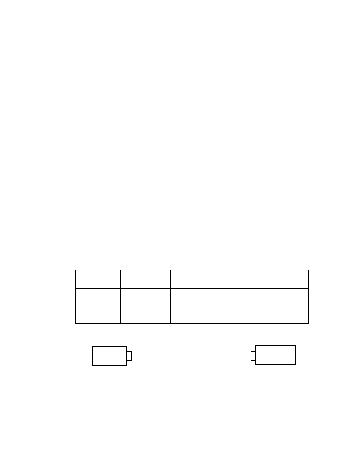
If connecting to a PC or modem equipped with a DB-9 connector, then use a straight-through cable
with one end terminated with a DB-9 male connector and the other end with a DB-9 female
connector. Plug the male end into the SLTA-10 Adapter and the female end into the serial I/O
port.
Table 5 PC DB-9 to DB-9 Connection
Signal Name PC Connector
DB-9 Male
RxD Pin 2 Pin 2 Pin 2 Pin 2
TxD Pin 3 Pin 3 Pin 3 Pin 3
Signal Ground Pin 5 Pin 5 Pin 5 Pin 5
PC (DTE)
DB-9
female end
Figure 5 DB-9 to DB-9 Connection
Cable DB-9
Female
Cable DB-9
Male
DB-9
male end
SLTA (DCE)
DB9 Female
SLTA-10
(DCE)
SLTA-10 Adapter User’s Guide 26
Page 27
If using a PC or modem equipped with a DB-25 connector, then use a cable equipped on one end
with a DB-25 female connector and a DB-9 male connector on the other end. Plug the male DB-9
connector into the SLTA-10 Adapter and the female DB-25 connector into the PC.
Table 6 PC 25-Pin to DB-9 Connection
Signal Name PC Connector
DB-25 Male
RxD Pin 3 Pin 3 Pin 2 Pin 2
TxD Pin 2 Pin 2 Pin 3 Pin 3
Signal Ground Pin 7 Pin 7 Pin 5 Pin 5
PC (DTE)
DB-25
female end
Figure 6 PC 25-Pin to DB-9 Connection
Cable DB-25
Female
Cable DB-9
Male
DB-9
male end
SLTA (DCE)
DB-9 Female
SLTA-10
(DCE)
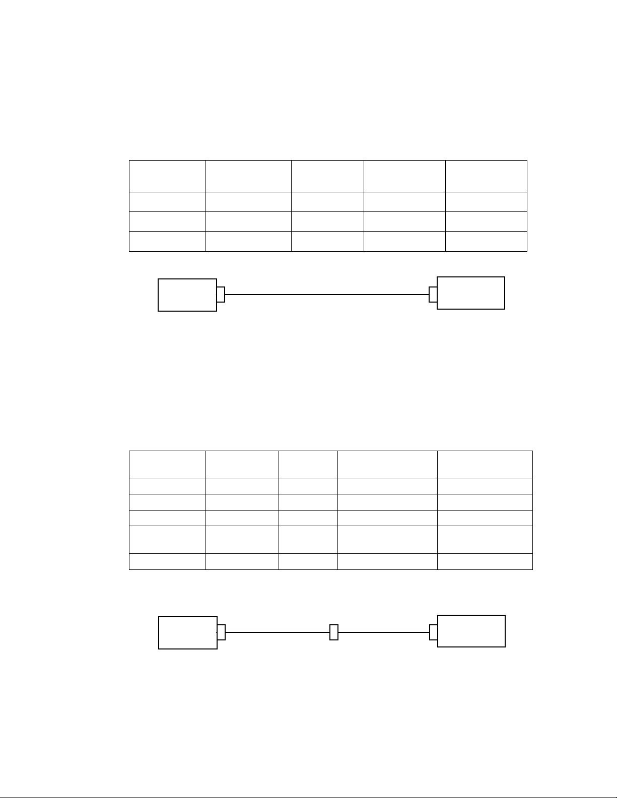
Attaching the SLTA-10 Adapter to a Modem
You must use the specific null modem cable described below to attach the SLTA-10 Adapter to a
modem.
Table 7 DCE Modem to SLTA-10 Adapter Connection (DB-9 to DB-9)
Modem Signal
Name
RxD—Pin 2 Pin 2 Pin 2-3 Pin 3 TxD—Pin 3
TxD—Pin 3 Pin 3 Pin 3-2 Pin 2 RxD—Pin 2
DCD—Pin1 Pin 1 Pin 1-4 Pin 4 DTR—Pin 4
DTR—Pin 4
RTS—Pin 7
GND—Pin 5 Pin 5 Pin 5-5 Pin 5 GND—Pin 5
Cable DB-9
Male
Pins 4 & 7 Pins
Null
Modem
4, 7 - 6
Cable DB9 Male SLTA-10 (DCE)
DB-9 Female
Pin 6 DSR—Pin 6
modem
DB-9
male end
Figure 7 DCE Modem to SLTA-10 Adapter Connection (DB-9 to DB-9)
SLTA-10 Adapter User’s Guide 27
Null
Modem
DB-9
male end
SLTA-10
Page 28
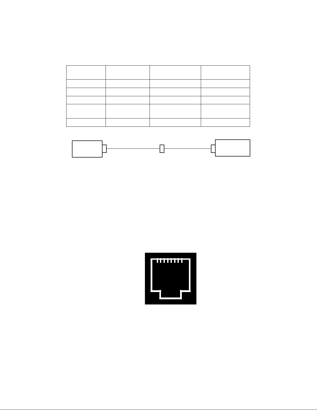
Table 8 DCE Modem to SLTA-10 Adapter Connection (DB-25 to DB-9)
Modem Signal
Name
RxD—Pin 3 Pin 3 Pin 3 TxD—Pin 3
TxD—Pin 2 Pin 2 Pin 2 RxD—Pin 2
DCD—Pin8 Pin 8 Pin 4 DTR—Pin 4
DTR—Pin 20
RTS—Pin 4
GND—Pin 7 Pin 7 Pin 5 GND—Pin 5
modem
Figure 8 SLTA-10 Adapter Null Modem Cable (DB-25 to DB-9)
Cable DB-25
Male
Pins 20 & 4 Pin 6 DSR—Pin 6
DB-25
male end
Cable DB9 Male SLTA-10 (DCE)
DB-9 Female
SLTA-10
Null
Modem
DB-9
male end
Attaching the SLTA-10 Adapter to a Network
The network connector for the SLTA-10 Adapter is an orange two-conductor block type. Use the 2pin conductor that comes with the SLTA-10 Adapter to connect to the twisted-pair network.
If connecting to a network which currently has an RJ-45 type connector, only the wires attached to
pins one (1) and two (2) of the RJ-45 connector are needed. These are the wires that need to be
stripped, inserted, and screwed into the SLTA-10 Adapter terminal block (J1). See figure 9 for a
diagram of the RJ-45 Terminal Block.
1
Figure 9 RJ-45 Terminal Block
8
SLTA-10 Adapter User’s Guide 28
Page 29

Chapter 4
Hardware Configuration
This chapter describes how to instal l and configure an SLTA-10 Adapter.
SLTA-10 Adapter User’s Guide 29
Page 30
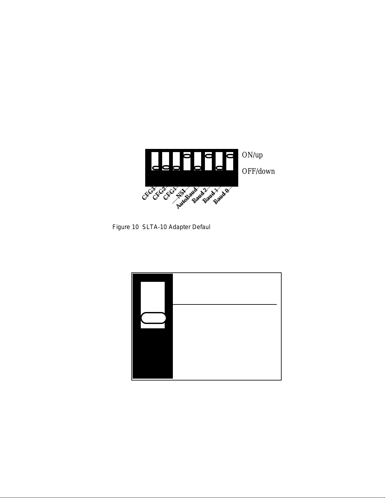
Configuring the SLTA-10 Adapter Hardware
There are eight configuration switches on the SLTA-10 Adapter's switch block (S1). These inputs
are read by the SLTA-10 firmware to configure or enable features. Figure 10 shows the factory
default settings for the SLTA-10 Adapter. Changes to the switch configurations will not occur
until the power is cycled on the SLTA-10 Adapter. The switches are read immediately after a
power reset.
The NSI switch selects between the legacy SLTA-10 MIP mode and a serial Network Services
Interface (NSI mode).
ON/up
OFF/down
12345678
CFG3 .
CFG2 .
Figure 10 SLTA-10 Adapter Default Switch Settings
CFG1 .
AutoBaud .
NSI .
Baud 2 .
Baud 1 .
Baud 0 .
Configuration Options
Interface Link Protocol Control (Switch1 / CFG3)
Buffered Link Protocol
ALERT/ACK Link Protocol
(default)
1
Figure 11 SLTA-10 Adapter Link Protocol Switch1 / CFG3
Switch1 / CFG3 controls the network interface link protocol used between the SLTA-10 Adapter
and a local host, when in MIP mode. For NSI mode, leave this switch in the default position. Two
link protocols are available for the SLTA-10 MIP mode: the SLTA-10 Adapter ALERT/ACK link
protocol and the buffered link protocol.
The ALERT/ACK link protocol is designed for host computers that cannot accept asynchronously
occurring streams of serial data at high speed. For example, a PC running DOS or Windows
SLTA-10 Adapter User’s Guide 30
Page 31

cannot guarantee receipt of all characters in an input stream appearing back-to-back on a COM
port . ALERT/ACK link protocol (down position) is the default setting for the SLTA-10 Adapter.
When the SLTA-10 Adapter uses the ALERT/ACK protocol and it wishes to send data to the host,
it first sends a single ALERT character (hex 01). The host then responds with an ALERT ACK
character (hex FE) to indicate its readiness to accept the rest of the data. The ALERT/ACK
protocol places timing requirements on the host, and if these timing requirements are violated, a
driver error occurs. After the host network driver has sent the ALERT ACK character, it enters a
tightly controlled loop for accepting the remaining characters—usually with interrupts disabled.
If this option is enabled (switch in down position), the ALERT/ACK protocol will also be used when
the host wishes to send data to the SLTA-10 Adapter.
The buffered link protocol (up position) is designed for host computers and applications that can
accept and buffer back-to-back serial data without losing characters. For example, most real-time
operating systems and
SLTA-10 Adapter simply sends the uplink message without any handshake with the host. The
SLTA-10 Adapter does not support hardware handshake or XON/XOFF software flow control when
directly attached to a host. If the buffered link protocol option is enabled (up position), the
buffered protocol is also used when the host wishes to send data to the SLTA-10 Adapter. The
buffered link protocol should not be used when CFG2 is set to the
See
Buffered Link Protocol
buffered link protocol.
/dev/tty
in Chapter 9 for additional application restrictions when using the
drivers in UNIX systems have this capability. In this case, the
Remote Host
state (up position).
Modem Support (Switch 2 / CFG2)
Remote Host (modem)
Local Host
(default)
2
Figure 12 SLTA-10 Adapter Host Switch2 / CFG2
Switch2 / CFG2 controls the use of the SLTA-10 Adapter with a modem. If the SLTA-10 Adapter
is connected directly to a host, then CFG2 should be set to the
This is the SLTA-10 Adapter default. If the SLTA-10 Adapter is connected to a modem, then
CFG2 must be set to the
(down position).
Remote Host
state (up position) and CFG3 must be set to ALERT/ACK
Local Host
state (down position).
SLTA-10 Adapter User’s Guide 31
Page 32

Network Disable (Switch3 / CFG1)
Network Disable
On
Network Enable (default)
(Disable Off)
3
Figure 13 SLTA-10 Adapter Network Switch 3 / CFG1
Switch 3 / CFG1 enables (down position) or disables (up position) network communications after
reset. If disabled, the SLTA-10 Adapter will not be able to communicate on the network after a
reset until it receives an
niFLUSH_CANCEL
command from the host.
The SLTA-10 Adapter prevents network communications by entering a
causes the SLTA-10 Adapter to ignore all incoming network messages and prevents all outgoing
network messages,
the service LED will light but no service message will be sent. This
prevent any other network management tools from performing network management functions on
the SLTA-10 Adapter before the SLTA-10 Adapter’s host has a chance to perform any of its own
network management functions. This state is canceled with the
the host.
An SLTA-10 Adapter network driver may automatically enable network communications when the
SLTA-10 Adapter is opened. For example, by default, the DOS network driver enables network
communications by automatically sending the
Adapter is opened and when it receives an uplink message from the SLTA-10 Adapter indicating
that it has been reset. If the host application needs to configure the SLTA-10 Adapter before
enabling network communications, the /Z option on the DOS network driver command line must
be used to leave network communications disabled after the SLTA-10 Adapter is opened. When
the /Z option is specified and CFG1 is set to
explicitly send the
The Windows NT network driver does not provide a /z option. When using the Windows NT
network driver, network communication will proceed without any action by the host application if
Switch3/CFG1 is in the
Disable On
If CFG1 is set to
communications after a reset by going directly to the
without requiring the
position, the host application must explicitly send the
even service pin messages
niFLUSH_CANCEL
Network Enable
Network Enable
niFLUSH_CANCEL
command after reset.
(down position), the SLTA-10 Adapter will enable network
. In the disabled state, if the service pin is pressed
FLUSH
niFLUSH_CANCEL
niFLUSH_CANCEL
Network Disable On
position. Otherwise, if Switch3/CFG1 is in the
NORMAL
command.
command when the SLTA-10
, the host application itself must
niFlush_CANCEL
state, thus allowing communications
state. This state
FLUSH
state is provided to
command from
command.
Network
SLTA-10 Adapter User’s Guide 32
Page 33

If the SLTA-10 Adapter is used with a modem, and the application requires the SLTA-10 Adapter
to dial out to a host in response to a message from the network, then CFG1 must be set to
Enabled
.
Network
If the modem is set to receive incoming calls only, then the host can disable the
the connection is established, in which case CFG1 can be set to either position. Table 9
summarizes these options:
Table 9 SLTA-10 Adapter Network Disable Switch Configuration
Network
Disable
Input
Disabled
(up position)
Disabled
(up position)
Enabled
(default)
(down
position)
DOS Driver ‘
/Z ’ Option
Specified Host application
Not specified
(default)
Don't care Immediately after reset
When SLTA-10 Adapter
Enables Network
Communications
command
Opening network driver
FLUSH
Serial Network Services Interface (Switch4 / NSI)
NS I Mode F irm ware
( defaul t)
state after
M IP Mode Firmware
4
Figure 14 SLTA-10 Adapter Firmware Switch 4 / NSI
The SLTA-10 Adapter has an SLTA-10 NSI-mode firmware switch which is Switch4 / NSI. It is
factory set in the up position for use of the SLTA-10 NSI mode firmware. The down position is for
the MIP mode firmware.
SLTA-10 Adapter User’s Guide 33
Page 34

Autobaud (AB)
The switch (5) labeled AB on the SLTA-10 Adapter is used to select automatic baud rate
detection—the autobaud feature. Autobaud must not be used when the SLTA-10 Adapter is used
with a modem. When autobaud is enabled, the SLTA-10 Adapter matches the serial bit rate of a
local host. When powered, the SLTA-10 Adapter looks for a ‘0’ byte from the host. The SLTA-10
Adapter cycles through all the serial bit rates until a ‘0’ is recognized. To initialize the SLTA-10
Adapter, the host must transmit eight binary zeroes (or ASCII NULs), spaced at least 50ms apart.
The SLTA-10 Adapter will try all of its bit rates until the zero character is recognized correctly,
and will respond with an ALERT ACK
rate. The SLTA-10 Adapter DOS network driver sends this sequence automatically if the
autobaud option
is specified. The default for an SLTA-10 Adapter is
(/A)
character
(hex FE) when it selects the matching serial bit
Autobaud Disable
.
Autobaud Enabled
Autobaud Disabled
(default)
Baud Determined by
Switches 6, 7, and 8
5
Figure 15 SLTA-10 Adapter Autobaud Switch 5 / AB
If the /A option is specified for the DOS network driver, the driver sends the autobaud sequence
every time the driver is opened. However, if the AB option is enabled, the driver must re-send the
autobaud sequence every time the SLTA-10 Adapter cycles power.
For the Windows NT network driver, there is no /A option. Using the Windows NT driver, the
autobaud sequence is attempted following power up if
(the default) autobaud will not be attempted.
Autobaud Enabled
is selected, otherwise
Serial Bit Rate (Switches[6..8] / BAUD[2..0])
Switches 6 to 8, named BAUD[2..0], are used to set the SLTA-10 Adapter serial bit rate. This
setting is only used if autobaud operation is disabled. There are eight available bit rates. The
SLTA-10 Adapter is configured for 38,400 bps with autobaud disabled by default.
All data are transmitted using 1 start bit, 8 data bits, no parity bits, and 1 stop bit.
The /B option is used to specify the serial bit rate to the DOS network driver.
For the Windows NT network driver, there is no /B option. When using the Wi ndows NT driver,
the serial bit rate is configured using the SLTALink Manager as explained in Chapter 7.
SLTA-10 Adapter User’s Guide 34
Page 35

678
115, 200 bps
678
9 600 bps
678
678
678
Figure 16 SLTA-10 Adapter Serial Baud Rate Switches 6, 7, and 8 / BAUD[2..0]
Table 10 SLTA-10 Adapter Autobaud Switch Configuration
Autobaud
Switch
BAUD Switches ‘ /A ’ Option on
57,6 00 bps
(d efault)
38,4 00 bps
19,2 00 bps
DOS Driver
678
678
678
‘ /B ’ Option on DOS Driver
2 400 bps
1 200 bps
300 bps
down
position
up
position
SLTA-10 Adapter User’s Guide 35
Specifies actual
baud rate
Don't care Must be specified Specifies actual baud rate
Don't care Specifies actual serial bit
rate. Must match switchselected baud rate
Page 36

Configuring the SLTA-10 Adapter Software
The types of messages passed between the host a nd the SLTA-10 Adapter are determined by
EEPROM configuration options. These options are described under
Configuration Options
The
Network Disable Option
application messages.
in Chapter 3 of the
affects whether or not the SLTA-10 Adapter can send and receive
ONWORKS
L
Host Application Programmer's Guide
Network Interface
.
The buffer configuration parameters can be changed at any time by sending
network management messages to the SLTA-10 Adapter, either from a host (using local network
management messages) or over the network from a network management tool. See the
Chip Data Book
control the partitioning of RAM for buffers. The following tables summarize the memory usage of
the default configurations for the respective two firmware versions resident on the SLTA-10
Adapter. The tables also list the maximum size of the buffer memory pool. If the SLTA-10
Adapter is configured to use more bytes than are available in the pool, it will behave erratically
since the RAM is used by t h e SLTA-10 firmware.
, Appendix A, for details of the data structures within the Neuron Chip that
Table 11 SLTA-10 Adapter Default EEPROM Configuration
Write Memory
Neuron
Configuration Parameters Default Setting
Initial State Unconfigured
Explicit addressing Enabled
Network variable processing Host Selection
Program ID string "SLTA10" (Mip
Mode)
80-00-01-01-0300-xx-3C
(NSI Mode)
Table 12 SLTA-10 Adapter MIP mode Default Buffer Configuration
MIP-mode Buffer Parameter Default Count Default Size
in Bytes
Receive transaction buffers 8 13 104
Transmit transaction buffers 2 28 56
Application input buffers 15 255 3825
Application output buffers 7 255 1785
Network input buffers 31 255 7905
Network output buffers 2 255 510
Priority app. output buffers 5 255 1275
Priority net. output buffers 2 255 510
Total bytes used for buffers 15970
SLTA-10 Adapter User’s Guide 36
Default Total
Bytes
Page 37

The NODEUTIL node utility application, available on Echelon’s web site, can be used to modify
the MIP mode buffer configuration from a PC host. See the README.TXT file included with
NODEUTIL for details.
By default, the SLTA-10 NSI-mode program ID consists of 8 bytes of program identification
information (80-00-01-01-03-00-xx-3C, where ‘xx’ is determined by the transceiver being used).
The host application must change this program ID to indicate its application. This is done
automatically in LNS by the LCA Object Server. If not using the LCA Object Server, the host
application needs to send local write-memory network management messages to change the
program ID. See the
Table 13 SLTA-10 Adapter NSI-mode Default, and Minimum, Buffer Configuration
LNS Host API Programmer’s Guide
for further information.
NSI-mode Buffer Parameter Default Count Default Size
in Bytes
Receive transaction buffers 16 13 208
Transmit transaction buffers 2 28 56
Application input buffers 3 255 765
Application output buffers 3 255 765
Network input buffers 2 66 132
Network output buffers 2 66 132
Priority app. output buffers 3 255 765
Priority net. output buffers 2 66 132
Total bytes used for buffers 2955
Note: It is very important that the LNS application change the SLTA-10 Adapter’s NSI
mode program ID. The Network Services Server (NSS) uses the program ID as a
unique identifier of a device's external interface. The first device encountered by the
NSS with a given program ID defines the external interface for all devices with that
program ID. To ensure that the NSI mode SLTA-10 Adapter’s unique external interface
is recognized by the NSS, it must given a unique program ID.
Default Total
Bytes
SLTA-10 Adapter User’s Guide 37
Page 38

SLTA-10 Adapter User’s Guide 38
Page 39

Chapter 5
The SLTA-10 NSI Mode Software
This chapter describes the Windows NT software used with the
SLTA-10 NSI mode. This software is available in the Connectivity
Starter Kit (Model 58030-01) as part of the LNS Developer’s Kit for
Windows (Model 34303), versions 1.5 and higher, and on the Echelon
web site at www.echelon.com.
Skip this Chapter if you are using the SLTA-10 MIP mode.
SLTA-10 Adapter User’s Guide 39
Page 40

SLTA-10 NSI Mode Software Overview
The SLTA-10 Adapter is not shipped with any software. The Windows NT driver and SLTALink
Manager software are supplied in the Connectivity Starter Kit and as part of the LNS Developer’s
Kit for Windows.
The SLTA-10 NSI mode set-up installs three pieces of software:
the SLTA-10 NSI mode Windows NT Driver,
a “stub” driver to run legacy DOS and Windows 3.1x applications, and
the SLTALink Manager software.
The SLTA-10 Adapter includes firmware that moves the upper layers of the LonTalk Protocol from
the Neuron Chip within an SLTA-10 Adapter and onto a host processor. This firmware allows the
SLTA-10 Adapter to be used by a host application to send and receive LonTalk messages. The
firmware in the SLTA-10 Adapter is loaded in ROM and cannot be reprogrammed.
Using the SLTA-10 NSI mode, the host application may be one of two types. T he first type of host
application is an LNS-based application, developed with the LNS Developer’s Kit for Windows.
The second type of application is a legacy DOS or Windows 3.1x application; these applications
make use of the “stub” driver declared in the
NT driver. Echelon does not support 32-bit Windows applications that are not based on the LNS
software accessing the Windows NT driver.
config.nt
file, which in turns accesses the Windows
Windows NT Software Installation Procedure
Prior to installation, ensure that the computer is running the Windows NT Operating System
(version 3.51 or higher for a direct connect interface; version 4.0 or higher for use with modems).
The SLTA-10 software cannot be installed from DOS, or a DOS shell, nor can it be installed on
Windows 3.1, or Windows 3.11, or Windows 95.
1. Before installing the software, make sure that you have logged in as Administrator.
2. Close all open programs.
3. Insert the installation diskette into the PC.
4. Click the Start button on the Windows task bar and select the run command. (If using with
Windows NT 3.51: Within Program Manager, choose the Run command from the File
menu.)
5. When prompted for a program name, enter the following:
A:\SETUP.EXE
If necessary, replace A: with the drive letter which corresponds to the drive containing the
SLTA-10 NSI mode installation diskette.
6. When prompted click the button marked “Next >”.
SLTA-10 Adapter User’s Guide 40
Page 41

7. When prompted for a destination directory, enter the desired installation directory. By
default this directory is
installed and have registered a different path in the Windows Registry. The path may be
modified using the “Browse” button.
c:\lonworks
, unless previous L
ONWORKS
products have been
8. The next screen presented is shown in figure 17. This will determine the L
naming convention used for the SLTA-10 adapter.
ONWORKS
Figure 17 L
9. Clicking the “Next” button concludes installation. At the prompt to restart the computer,
remove the SLTA-10 NSI mode installation diskette and restart the computer. Note that the
Windows operating system will not recognize the SLTA-10 adapter until the computer is
restarted.
ONWORKS
Device Naming Convention
Windows NT Software Installation Results
The Windows NT installation software loads a selection of new files and updated Echelon files to
different locations on the PC's hard drive. The function and location of these files can be found in
readme.txt
SLTA-10 Adapter User’s Guide 41
.
Page 42

SLTA-10 Adapter User’s Guide 42
Page 43

Chapter 6
The SLTA-10 Mip Mode Software
This chapter describes the SLTA-10 MIP mode software shipped with
the Connectivity Starter Kit (Model 58030-01) and on the Echelon web
site at www.echelon.com. This software is basically an updated version
of the SLTA/2 adapter software.
There is no 32-bit Windows driver available for the SLTA-10 MIP mode.
Skip this Chapter if you are using the SLTA-10 NSI mode.
SLTA-10 Adapter User’s Guide 43
Page 44

SLTA-10 MIP Mode Software Overview
The SLTA-10 Adapter is not shipped with any software. The SLTA-10 MIP mode software and
drivers are supplied in the Connectivity Starter Kit and must be ordered separately. The software
includes ANSI C source code for HA, a sample host application for MS-DOS that can be used as a
basis for a user-developed host application on other host platforms. This application provides
examples of sending and receiving network variable messages, as well as allowing a node based on
an SLTA-10 Adapter to be installed and bound by a network management tool such as the
LonManager LonMaker Installation Tool or the LonBuilder network manager.
A network driver for DOS permits the SLTA-10 Adapter to be used with DOS applications. Source
code for a DOS network driver is provided as a basis for a user-developed network driver for other
hosts or operating systems. On a separate diskette, DLL software is provided to make it easier to
use the network driver under the Microsoft
An executable program and source code is also provided for a Host Connection Utility (HCU),
which may be used to initiate and terminate the host to SLTA-10 Adapter connection when the
SLTA-10 Adapter is used with a remote host. An example written in Neuron C is also provided as
a basis for user-developed nodes on a L
remote host.
The SLTA-10 Adapter includes firmware that moves the upper layers of the LonTalk Protocol off
the Neuron Chip within an SLTA-10 Adapter onto a host processor. This firmware allows the
SLTA-10 Adapter to be used by a host application to send and receive LonTalk messages. The host
application may be a custom application as described in the
Programmer's Guide
. The host application may also be a network management or monitoring
application based on the LonManager API, LonManager LonMaker installation tool, or
LonManager DDE Server. The firmware in an SLTA-10 Adapter is fixed in ROM and cannot be
reprogrammed.
®
Windows 3.1x operating system.
ONWORKS
network that need to initiate outgoing calls to a
ONWORKS
L
Host Application
Installing the SLTA-10 MIP Mode Adapter Software
The SLTA-10 Adapter software is supplied in the Connectivity Starter Kit as a diskette. The
SLTA-10 DOS driver operates under DOS, Windows 3.1x, and Windows 95 operating systems. To
install the SLTA-10 Adapter software, follow these steps:
1. Place the diskette in one of the disk drives of your PC. This will typically be the A: or
drive. Under the Windows 95 operating system, open a DOS console.
2. Start the automatic installation procedure by entering:
A:INSTALL [ENTER]
Substitute your disk drive name for the A: if you are using a different drive.
3. You will be asked to enter the name of your L
ONWORKS
is the default.
The SLTA-10 Adapter software will be installed in the
directory, with the exception of the DOS network driver
in the
your
CONFIG.SYS
sub-directory of your L
BIN
file, follow the instructions in Chapter 8.
ONWORKS
directory. To install the DOS network driver into
installation directory.
sub-directory of your L
SLTA
LDVSLTA.SYS
. This file will be installed
C:\LONWORKS
ONWORKS
B:
SLTA-10 Adapter User’s Guide 44
Page 45

The
directory will contain the following files:
SLTA
• Read-Me File. The
README.TXT
file includes a list of all the files on the distribution disk, and
also includes any updates to the documentation that occurred since the SLTA-10 Adapter
documentation was printed.
• DOS Network Driver Sources. The SLTA-10 Adapter DOS network driver source code is
contained in the
LDVSLTA
directory. These files can be used as the basis for creating drivers
for hosts other than PCs running DOS (see also the UNIX network driver sources). See
Chapter 8 for a description of the SLTA-10 Adapter DOS network driver and Chapter 9 for a
description of how to write an SLTA-10 Adapter network driver for other hosts. See Chapter 4
of the
ONWORKS
L
Host Application Programmer's Guide
must be supplied by a L
ONWORKS
network driver.
for a description of the services that
The source files to build the DOS driver are:
LDVSLTA.CFG
MAKEFILE
MDV_TIME.C
MDV_TIME.H
MSD_DEFS.H
MSD_DIFC.C
MSD_DRVR.H
Configuration file for Borland C.
Make file script for Borland C.
Code to manage the PC timer.
External interface definitions for the timer handler.
Data structure and literal definitions.
DOS driver interface functions.
DOS driver interface and literal definitions.
MSD_EXEC.C
MSD_FRST.C
MSD_IRQC.ASM
MSD_LAST.C
MSD_RAW.C
MSD_SEGD.ASM
MSD_SIO.C
MSD_TXRX.C
MSD_UART.H
Main open, close, read, and write processing.
Module to be linked first in the network driver.
Serial I/O interrupt procedure.
Module to be linked last in the network driver.
Direct serial I/O (modem) processing.
Defines data segment register for driver.
PC/AT UART
interface processing.
Single byte link layer processing.
Defines PC/AT UART registers.
• External Interface Files. External interface files included for use by network
management tools are contained in the
included for the transceivers available for the SLTA-10 Adapter. See
Host Node
in Chapter 3 of the
ONWORKS
L
directory. External interface files are
SLTA
Binding to a
Host Application Programmer's Guide
for a description of how to use these files to bind to an SLTA-10 Adapter node.
Appendix B of the
ONWORKS
L
Host Application Programmer's Guide
provides a
detailed description of how to modify these files to incorporate network variables
SLTA-10 Adapter User’s Guide 45
Page 46

and message tags. These interface files are provided in version 3 formats. External
interface files in version 3 format are contained in the
SLTA2\XIF_V3
directory.
The SLTA directories contain at least the following files:
NSLTA125.XIF
NSLTA78K.XIF
NSLTAFT1.XIF
For SLTA-10 Adapter with a TP/XF-1250 transceiver.
For SLTA-10 Adapter with a TP/XF-78 transceiver.
For SLTA-10 Adapter with a TP/FT-10 transceiver.
• Sample Host Application. A sample host application is contained in the
directory. See Appendix A of the
ONWORKS
L
Host Application Programmer's Guide
for a description of the example. The following files are included:
README.TXT
HA.EXE
A description of the sample host application.
An executable version of the sample host application for
DOS. The SLTA-10 Adapter DOS network driver must
be installed to run this application.
HA.C
NI_MSG.C
The main program for the example.
A general purpose network interface library that can be
used with any host application.
APPLCMDS.C
Functions to handle application layer network variable
commands
NI_CALLB.C
The host-bound network management dispatcher.
HA
APPLMSG.H
HA_COMN.H
NI_CALLB.H
APPLMSG.C
HAUIF.C
IOCTL.C
LDVINTFC.C
LDVINTFC.H
NI_MSG.H
NI_MGMT.H
Application message handler function prototypes.
The HA common declarations.
The definitions for the network management
dispatcher.
Functions to handle application network variable and
explicit messages.
Command-line user interface for the example.
I/O control function for Microsoft C.
Device interface driver.
Include file for device driver interface.
Definitions for network interface message structures.
Definitions for network management message
structures used by the exampl e.
SLTA-10 Adapter User’s Guide 46
Page 47

HAUIF.H
Definitions for the host application example user
interface.
MAKEFILE
MSOFT.MAK
HA_V3.XIF
HA_TEST.NC
DISPLAY.H
• Host Connect Utility. A sample host connection utility is contained in the
directory, with source code. See Chapter 12 for details. The files supplied are:
HCU.EXE
HCU_MAIN.C
HCU.CFG
MAKEFILE
MSD_DRVR.H
• Neuron C Connection Example. A sample Neuron C program is contained in the
NC_APPS
SLTA-10 Adapter can dial out and connect to a remote host computer. The files
supplied are:
directory. This program shows how a node on a network connected to the
A make file script for Borland C.
A make file script for Microsoft C.
n external interface file which may be used to bind
A
the example with LonBuilder.
A Neuron C program which may be loaded into a
Neuron emulator and bound to the sample host
application for testing.
A Neuron C include file to drive the Gizmo 2 I/O
module for the test example.
Executable file for the Host Connection Utility.
The main C source program.
Configuration file for Borland C.
Make file script for Borland C.
Driver definition include file.
HCU
DIALOUT.NC
GIZSETUP.NC
SLTA_ANM.H
Neuron C source program to dial out with the SLTA-10
Adapter.
An example Neuron C program for configuring the
SLTA-10 Adapter. Configures the EEPROM directories
of an SLTA-10 Adapter using the Gizmo 2 I/O module
as the user interface.
Definitions of SLTA-specific network management
messages.
Installing the Windows 3.1x DLL Software
A second diskette, labeled “LONWORKS Network Driver Interface for Windows 3.1x”,
contains the 16-bit Windows Dynamic Link Library (DLL) files. These files may be
used when developing a host application to run under Microsoft Windows 3.1x. T he
file
WLDV.DLL
The files
SLTA-10 Adapter User’s Guide 47
should be copied to your Windows directory (typically
and
LDV.H
LON.H
C:\WINDOWS
).
Page 48

should be copied to a directory in the include file search path of your C compiler. The
file
application linker. See Appendix A for information on using the Windows DLL.
Other Drivers
A UNIX network driver and source code for the SLTA-10 MIP mode is available on the
Echelon web site (http://www.echelon.com).
Chapter 9 discusses creating a SLTA-10 MIP mode driver for any host.
WLDV.LIB
should be copied to a directory in the library search path of your
SLTA-10 Adapter User’s Guide 48
Page 49

Chapter 7
Using the Windows NT Driver and SLTALink Manager
with SLTA-10 NSI Mode
This chapter describes the SLTALink Manager software, which
establishes and configures local and remote links from the host PC to
the SLTA-10 Adapter in NSI mode. A remote link requires a pair of
modems: one attached to the SLTA-10 Adapter and the other attached
to the host PC. The SLTALink Manager software control s a remote
SLTA-10 via modem through Windows’ Telephony Application
Programming Interface (TAPI) services under Windows NT 4.0 or later.
The SLTALink Manager determines when a standard driver open call in
a host application requires dialing and handles these cases. Thus, the
host application does not need to know if the network services interface
is a local SLTA-10 or a remote SLTA-10 Adapter.
NOTE: Remote SLTA-10 Adapters cannot be used with Windows NT 3.51
because Windows NT 3.51 does not include the 32-bit TAPI services used by the
SLTALink Manager software.
Skip this Chapter if you are using the SLTA-10 MIP mode.
SLTA-10 Adapter User’s Guide 49
Page 50

Software Overview
The SLTALink Manager is sophisticated software that compliments the SLTA-10 Adapter NSI
mode firmware in many various ways.
The SLTALink Manager is a standalone application that can monitor a modem line, answer an
incoming phone call, associate the incoming call’s SLTA-10 Adapter (and hence its network) with a
LON device, and then launch a pre-determined application for that particular network or SLTA-10
Adapter. Combined with a well-designed system architecture and a well-designed LNS host
application, the SLTALink Manager lets a L
PC through a pair of modems based on an event that occurs locally to the network.
The SLTALink Manager provides a graphical user interface for the creating, editing, and
diagnosing of “links”. Each link represents a particular SLTA-10 Adapter and its network. A link
identifies several important aspects of the set-up, including the type of connection (a remote
connection via modems or a local, direct connection), the COM port, the SLTA-10 Remote
Identifier (see below), the baud rate of the serial port on the SLTA-10 Adapter, and the dial-in
password, if any. In addition, the link indicates if a security callback is required and may be
associated with a host application. The link information is stored in a .s10 file, located by default
in the
c:\lonworks\bin\slta10
The SLTALink Manager application can associate a link with a LON device name and then
interface with the SLTA-10 NSI mode driver for Windows NT. The SLTALink Manager handles
automatically dialing in to the network from the PC host, providing the ability for applications
with no knowledge of modems or phone numbers to run remotely through a pair of modems. The
SLTALink Manager’s GUI can be used to connect or disconnect to a remote SLTA-10 Adapter. In
addition, the SLTALink Manager has a simple, programmatic way to interact with the SLTA-10
driver for Windows NT. This programmatic interface allows an application to send down a
particular phone number for an SLTA-10 Adapter to dial or to send down certain commands, such
as hang-up.
folder.
ONWORKS
network establish a connection to a remote
Finally, the SLTALink Manager includes many diagnostic functions.
The SLTA-10 Adapter Link Manager software is used to control a remote SLTA-10 via a set (2) of
modems by using the Telephony Application Programming Interface (TAPI) services which are
built into the Windows NT 4.0+ operating system.
When attached directly to a PC, SLTA-10 Adapters use so-called “local” links. In this case, the
SLTALink Manager software interacts with the Windows NT driver and configures the necessary
parameters.
NOTE: Remote SLTA-10 Adapters cannot be used with Windows 3.51 because Windows 3.51 does
not include the 32-bit TAPI services used by the SLTALink Manager software.
Upon invocation of the SLTALink Manager software (
shown in figure 18.
SLTA-10 Adapter User’s Guide 50
SLTALINK.EXE
), the main screen appears,
Page 51

Figure 18
SLTALink
Manager Main
Screen
Establishing
a
Communicat
ions Line for
Dialing in to
a Network
E
s
t
a
b
l
i
s
h
i
n
g
a communications line is the first task to be completed. Figure 19 displays t he
message that appears when Dialing Preferences is chosen from the Line menu. This
message will only appear when telephony information has not been provided. This
case usually occurs if the computer has never been configured to use a modem.
Fig
ur
e
19
Fir
st
Ti
me
Us
e Message
SLTA-10 Adapter User’s Guide 51
Page 52

This message in figure 19 may not be visible due to being covered by the SLTALink
Manager Dialing Preferences window. Moving the Dialing Preferences window should
reveal the message—if it exists. This leftmost window, shown in figure 20, will display
“???” for the “Dialing from:” indicator if there has been no dialing location created/chosen.
Figure 20 SLTALink Manager Dialing Preferences Window
Clicking on Dialing Properties will bring-up the Windows Location Information window
(figure 21) if the “Dialing from:” indicator reads “???”, or if TAPI information has been
previously entered — as shown in figure 20 as “Dialing from: The Office” — the Windows
Dialing Properties window (figure 22) will be displayed instead. The Dialing Properties
window is a tabbed subset of the Windows Telephony Control Panel.
Figure 21 Windows Location Information Window
SLTA-10 Adapter User’s Guide 52
Page 53

Figure 22 Windows Dialing Properties Window
Establishing a Communications Line for Calls Dialed out to the PC
The next step is to select a line/modem to monitor for incoming calls. Figure 23 shows the Monitor
Line window that is displayed when “Monitor for SLTA dial-in” is chosen from the Line menu.
Only one line or modem can be monitored at a given time by the SLTALink Manager software.
However, multiple modems may be used for dialing into a network concurrent with monitoring the
one modem.
SLTA-10 Adapter User’s Guide 53
Page 54

Figure 23 SLTALink Manager Monitor Line Window
The option list box will display the list of modems which have been set-up for use on this
computer. The list can be created/modified by using the Windows Modem Control Panel. Select
the line/modem to be used for incoming calls, then click OK.
Establishing Remote and Local Network Sites
Choosing Select/Action from the Link menu will display a screen similar to the screen shown in
figure 24. Figure 25 shows the default local setup.
Figure 24 Completed SLTALink Selection Window
Figure 25 Default SLTALink Selection
SLTA-10 Adapter User’s Guide 54
Page 55

Select “Local SLTA-10” and click Edit. This action will present a window allowing the ability to
customize the connection—including changing it from Local to Remote, or modifying the name.
Name of Link
The name of the link should be fairly verbose, and/or something easy to understand. This is the
descriptor for the connection and location.
Remote Identifier
The Remote Identifier is used to identify a specific link when a dial-in to the computer occurs. It
represents the remote SLTA-10 Adapter in a 12-byte string of characters or hexadecimal numbers.
This value here should match the value stored in the remote SLTA-10 Adapter. It can be entered
here as a string in single quotes, or as a series of hexadecimal numbers separated by dashes.
If this field is blank or all zeroes (
Identifier will be captured and stored here the next time this connection is made.
If this field is all FFs (
will be accepted. The identifier will not be stored on the PC. This is known as the wildcard
Remote Identifier. The questi on mark (?) is also accepted as the wildcard Remote Identifier. The
SLTALink Manager software translates “?” to all FFs.
The Update Identifier checkbox indicates that the remote identifier will be read from the SLTA-10
Adapter by the SLTALink Manager and the new value will be stored in the .s10 file the next time
this link is used.
The SLTALink Manager software allows a user to create two links with different names but the
same Remote Identifier. However, when a network dials-out to a PC with multiple links each with
the Remote Identifier, the user has no control over which link is selected, which could result in
undesired behavior.
FF-FF-FF-FF-FF-FF-FF-FF-FF-FF-FF-FF
00-00-00-00-00-00-00-00-00-00-00-00
) then any Remote Identifier
) then the Remote
Link Type
The type of link specifies whether the SLTA-10 is directly connected to the PC (Local), or if the
SLTA-10 is at a different location and must be accessed via a set of modems (Remote).
Configuring the Modem Line
Clicking on “Configure Line” will cause the selected modem’s property window to appear. The
property window will reflect the options available to the driver of the modem such as volume
control and dial-tone detect.
TAPI services will handle the structuring of the call based on the Location Information (see figure
21).
SLTA-10 Adapter User’s Guide 55
Page 56

SLTA Password
The Password box allows the user to enter the password for a remote SLTA-10 Adapter. Up to
eight characters may be entered. If entered, the password will be sent to the remote SLTA-10
adapter when a connection is made.
The password is not encrypted when stored on host computer.
Invoking an Application
The SLTALink Manager provides a space to enter the startup application for this link. This may
be a full executable path name, or the name of an application that can be found in the system’s
search path. Command line arguments may also added — including the special macros for link
connection variables:
%LINKNAME% Expands to the name of the link, enclosed in quotes.
%DEVNAME% Expands to the device name used by L
the logical device. This serves the same purpose a s %DOSNAME% does for
DOS.
%NSSNAME% Expands to the device name used by LonWorks LNS application, for SLTA-10s
this will be “SLTALONn”.
%DOSNAME% Expands to the DOS device name for the logical device, provided the VDD is
installed, which would be “LONn”.
%ID% Expands to the remote identifier. This is expressed as either a quoted ASCII
string, or as a series of hexadecimal numbers if the identifier contains nonASCII data.
%RESULT% Expands to an unquoted word that represents the success or fail reason of the
connection.
The startup application will be launched when a dial-in occurs for this link, or optionally, when a
manual connection is made to the link. It will not start up if the link is connected to due to an
“auto-connect” case.
ONWORKS
32-bit applications to access
Enabling a Callback
If a remote SLTA-10 adapter has callback enabled then it will expect a callback command
whenever someone dials in to it. Check the Enable box if you need to enable the callback feature.
The callback command includes a directory index that points to a phone number stored in the
remote SLTA-10 adapter. If callback is enabled then one of the remote directory numbers
(“Address 1” though “Address 5”) can be select to be used to call the host back.
See
Characteristics of a Well-Designed System
implement callback.
SLTA-10 Adapter User’s Guide 56
below for a description of how to successfully
Page 57

Diagnostics
A number of Diagnostic and testing services are provided via the Diagnostic Screen, accessed
through the Devices menu (see figure 26). The Test button ret r ieves status and error counts from
the SLTA-10 Adapter. The Service button will cause the SLTA-10 Adapter to broadcast a service
pin message on the network. The reset button causes a reset of the Neuron Chip in the SLTA-10
Adapter, but does not clear the Neuron Chip’s system image.
Some buttons are left for future releases of additional features.
Figure 26 Diagnostic Screen
The SLTALink Manager Programmatic Interface
The SLTALink Manager executable (
Once the SLTALink Manager is up and running, a program can connect to a known link by
executing
Quotes generally are needed since the link name can have embedded spaces. Another form will
disconnect the specified link:
Another form allows a phone number override:
Another form allows a password override:
SLTALINK.EXE
C:\lonworks\bin\sltalink.exe "Remote"
C:\lonworks\bin\sltalink.exe "Remote" /D
C:\lonworks\bin\sltalink.exe "Remote" /# "1 (415) 867 5309"
C:\lonworks\bin\sltalink.exe "Remote" /P "passwd"
with a command line argument:
SLTALINK.EXE
) provides for a command line invocation.
SLTA-10 Adapter User’s Guide 57
Page 58

The /P and /# options may be combined.
Note that the phone number is in the form of a
code followed by a space, followed by an area code or city code enclosed in parenthesis, followed by
a space and the rest of the phone number. TAPI will take this and decide how to translate it before
the dial-out, based on your dialing preferences. Even if the call is local, the number should include
the area code / city code. This is the same format as the number that appears in the link selection
dialog under the Port/Number column.
canonical
number. This is defined as a country
Using the DOS “Stub” Driver
The DOS stub driver, which is added as part of the install, allows DOS and Windows 3.1x
applications to run on top of the SLTA-10 driver for Windows NT. The following line is required in
the
CONFIG.NT
DEVICE=%SystemRoot%\system32\PCLTDOS.SYS /D
This makes the device ‘LONn’ available for DOS applications.
When LONn is opened by an application and the SLTALink Manager has been configured to
associate LONn with a particular link, the SLTALink Manager will auto-connect to the SLTA-10
Adapter locally or remotely. That is, the SLTALink Manager automatically dials-in to the network
defined by the link if required.
file that is loaded on startup:
n
Characteristics of a Well-Designed System
Well understood strategies used with the SLTA-10 Adapter and the SLTALink Manager for the
following system functions are essential for reliable system design: Call Initiation, Call
Termination, and Monitoring.
Call Initiation
The four scenarios for call initiation are: dial-in to the network only, dial-out to the remote PC
only, dial-in / dial-out, and callback.
Dial-In to the Network Only
In the most straight-forward case, a user launches an application. The application opens the
driver, which is associated with a particular link. The SLTALink Manager application dials the
phone number in the link (or the phone number the application passes down to the SLTALink
Manager perhaps to a generic link) and establishes the connection. Similarly, the user could select
the link from within the SLTALink Manager and cause a manual connection. At this point, either
the SLTALink Manager would launch the pre-determined application from the information stored
in the link file or the user could manually launch the application. In all of these cases, the user is
assumed to initiate the call. The user could be a human operator or another application that
initiates a dial-in based on a clock, for example.
For the dial-in only scenario, the system strategy issues primarily have to do with associating the
link or phone number with the application. Where there are only one or two links, this is very
easy. When one PC host can be connected to many different networks, we offer two standard
solutions. The first is to have the user navigate the SLTALink Manager’s GUI. Under the Link
menu, the Select item lists approximately 40 links (of the 1000 possible). The second solution is a
SLTA-10 Adapter User’s Guide 58
Page 59

monitoring application that programmatically interacts with the SLTALink Manager to send down
the appropriate phone number, perhaps to a generic out-going link.
Dial-Out to the Remote PC Only
The three common approaches for initiating a dial-out are: sending a network variable update to
the SLTA-10 Adapter, sending an AddMyNSI message to the SLTA-10 Adapter, or sending an
explicit message from a “Helper/Dialer” node on the network.
In the first case, the remote host application needs to have an explicitly-bound input network
variable and the SLTA-10 Adapter’s NSI mode EEPROM must be configured correctly. See
Chapter 11 for more information on configuring the SLTA-10’s EEPROM. See also
Termination
In the second case, the remote host PC is assumed to have the NSS engine and a second NSI on
the network (perhaps a service technician with a laptop running a PCC-10 card) is required to
send the AddMyNSI message. Also, SLTA-10 Adapter’s NSI mode EEPROM must be configured
correctly. See Chapter 11 for more information on configuring the SLTA-10’s EEPROM.
In the third case, a custom Neuron Chip application must be written.
All three cases could be used with the same SLTA-10 Adapter.
In the dial-out only case, besides the call initiation, the SLTALink Manager must be able to launch
the appropriate application – with the correct database and device driver name. One system
solution is to create a separate link for each SLTA-10 Adapter. Each link then stores the Remote
Identifier of its SLTA-10 Adapter after the first connection. Upon connection, the appropriate
application and command line arguments stored in the link get launched. A second viable
approach is to create a generic link that uses the wild card as a Remote Identifier to launch a
generic application using command line arguments to specify the appropriate network or database
and device driver name. These arguments are available and described above under
Application
below.
.
Call
Invoking an
Note: if the device driver information used in the application does not match the device driver
name being used by the link, the newly launched application can open a second device driver –
which may result in an attempt to dial-in to the network. Since the modem is still presumably in
use with the original dial-out call to the host PC, the second call will fail. The result is a systemlevel failure.
Dial-In / Dial-Out
These scenarios are the combinations and permutations of the above. However, it needs to be
pointed out that not all dial-in strategies can co-exist with all dial-out strategies. For example, if
the dial-out strategy involves having the SLTALink Manager match the incoming call to the wild
card Remote Identifier and if the dial-in strategy requires a separate link for each SLTA-10
Remote Identifier, then it is possible that a call initiated from the network will be received by the
SLTALink Manager and will be matched with the link created for the dial-in case. The correct
application may not be launched and a system-level failure may occur.
SLTA-10 Adapter User’s Guide 59
Page 60

Callback
The SLTA-10 Adapter callback functionality works as follows: A call is initiated from some remote
PC to an SLTA-10 Adapter on a network, which must have its NSI mode EEPROM configured to
require callback. See Chapter 11 for more information on configuring the SLTA-10’s EEPROM.
The SLTA-10 Adapter answers; the remote PC identifies to the SLTA-10 Adapter one of t h e SLTA10 Adapters directory entries to use for the callback. An SLTA-10 configured to require a callback
will not accept any other direction from the host at this time. The original call is terminated, and
the SLTA-10 Adapter calls the phone number indicated in its directory. Note: this does NOT need
to be the phone number of the original remote PC that initiated the call. Typically, the SLTALink
Manager on the remote host dialed answers the call and launches the appropriate application.
Several possible system-level failures include:
The original remote host expects to receive the callback, but the directory index reflects the
phone number of another remote host.
The original remote host application opens an LNS database and initiates the first call. The
callback is directed back to the original remote host PC. The SLTALink Manager on this PC
receives the callback just like any other normal dial-out call and launches the application
contained in the link. At this point there may be two copies of the application open.
Depending on sharing configuration, the second application may fail because appropriate LNS
database in already opened.
To prevent these failures, Echelon recommends that the initial call should either be a manual
connection from within the SLTALink Manager or the initial call should originate from a “dummy”
application that terminates itself without opening the LNS databases.
Call Termination
The four scenarios for call termination include: termination of the host application, application
controlled hang-up, a manual disconnect in the SLTALink Manager, and time-out. In all of these
cases, the important system-level issues involve making sure that the termination strategy is
compatible with the call initiation strategy.
The behavior of an application at termination is not always known. By default, applications based
on the Object Server of LNS 1.5 and higher should exhibit two types of behavior. First, if the
interface adapter is an SLTA-10 Adapter in NSI modem using modems and there are explicitly
bound network variables to the host application, then at the LNS application’s termination the
host network variables and their connections should not be removed from the LNS database. This
behavior facilitates the use of the first case described under
a network variable update addressed to the SLTA-10 Adapter’s NSI mode results in a call being
initiated. Second, if the interface adapter is not an SLTA-10 Adapter in NSI modem using
modems or there are no explicitly-bound network variables to the host application, then at the
LNS application’s termination, any host network variables and their connections are removed
from the LNS database and the other nodes in the network. In addition, if the interface does not
host the LNS database, upon termination of the LNS application the interface is deconfigured.
The second behavior described would be desirable in the event that multiple remote host PCs
needed to be able to dial-in to the same network. As long as no explicitly-bound network variables
were left when the host applications terminated, then several remote PCs could share one SLTA-
Dial-Out to the Remote PC Only
where
SLTA-10 Adapter User’s Guide 60
Page 61

10 Adapter. Note: this assumes that the NSS engine exists somewhere on the network and is not
located on one of the remote PCs sharing the single SLTA-10 Adapter.
Both an application controlled hang-up (using the
manual disconnect in the SLTALink Manager will terminate the phone call; however, neither
results in the termination of the host application. In these scenarios the host application remains
running as the call can be re-established by the host application itself, by a manual connect in the
SLTALink Manager, or a dial-out initiated on the network. The disadvantage of these system
solutions is that they do not scale well to monitoring multiple networks on one PC. The result is
many applications continually and concurrently running on the same PC. Also, one possible
system failure to avoid is that the SLTALink Manager settings may result in multiple copies of the
host applications.
By default, the SLTA-10 NSI mode will terminate a phone call after three minutes with no traffic
going across the modems. As with the application-controlled hang-up and the manual disconnect
in the SLTALink Manager, this scenario does not result in the application terminating. This
scenario therefore carries the same advantages and disadvantages as those described in the
previous paragraph.
SLTALINK.EXE
programmatic interface) and a
Monitoring: Application Termination Strategy
There are three strategies for terminating the remote LNS monitoring application.
The first strategy is to require user intervention to shut down or terminate the application. No
special software must be written for this case. For the dial-in to a network scenario when the call
is user initiated, the user is presumably available to shut down or terminate the application. In
the dial-out case, the requirement of user intervention to terminate the application means that
every call from a network is seen by an user. If the network is sending alarms, user intervention
is highly desirable.
The second approach requires a node on the network to send a network variable update to the host
when the network no longer requires the host application to be up and running. When the host
application receives this network variable, it should enter a shut-down routine. This approach
places the responsibility on the network to determine when the host application is needed and
requires a hook in the monitoring application, but provides a level of automation when dial-out is
used.
The third approach is the most blunt. In this scenario, the remote host application terminates
itself either after completing a series of actions or based on a timer. We do not recommend this
scenario for the general scenario, but it has certain appeal for some applications. For example, a
connection may be established through dial-in or dial-out based on a timer. The host application
could then take a series of measurements from the network, log them to a file, and then terminate
itself.
Monitoring: Missing Messages after a Dial-Out
In general, the message that triggers a dial-out from the SLTA-10 on the network to a remote PC
host is lost.
When a network variable update is sent to the SLTA-10 Adapter and no phone connection is
currently up and running, the SLTA-10 Adapter is typically configured to dial-out to the host. On
the remote PC host, the incoming call is answered by the SLTALink Manager application. The
SLTA-10 Adapter User’s Guide 61
Page 62

SLTALink Manager then reads the Remote Identifier in the SLTA-10 Adapter and searches
through all the .s10 files for a match. The SLTALink Manager application then typically launches
the application listed in the link with optional command line arguments available, for example, to
open the correct LNS database with the correct device name. The process of opening the LNS
application results in the buffers of the SLTA-10 Adapter being over-written; thus, the original
message is lost. Since this message network variable update is by definition important enough to
warrant establishing a connection to the host, a system strategy is required so that this data
reaches the host.
The two basic system strategies are: (1) to have the node on the network continue to send out the
network variable update until the host application sends a message to the node telling it to stop, or
(2) to have the host application seek out the information upon being launched. The first approach
places the burden on nodes in the network; the second approach places the burden on the host
application. The first is more direct and is likely to result in the information getting to the host
more quickly. The second approach has the primary advantage that no special Neuron Chip
application code is required; also, since the call initiation and host application launch may require
minutes, the time it takes the host application to poll several network variables is not significant.
In the best scenario, upon being launched the host application would first check with a datalogging
node on the network that records alarms and also the system state, mode, or health information.
Monitoring: LNS Application Design Issues
A well-designed LNS monitoring application using the SLTA-10 Adapter through modems should
use the correct version and layer of LNS, should handle initialization of the application with the
correct LNS database and device driver name, and should have a phone call session termination
and an application termination strategy.
The remote monitoring application is based on LNS Object Server of LNS 1.5 or higher.
Applications based on the LNS 1.0 and LNS 1.01 do not behave well by default and do not allow
for certain dial-out scenarios. Applications written at the NSS layer are not supported for use
with the SLTA-10 Adapter across a pair of modems.
The remote monitoring application should open the correct LNS database with the correct device
driver. Specifically, the mapping of the Remote ID to the LNS database should be handled by the
application. We suggest using the command line arguments with the information available from
the SLTALink Manager. Note LNS capacity keys may need to be hard-coded in the monitoring
application.
Finally, the LNS application needs to implement a termination strategy that meets the needs of
the application and the system.
Good Practices / Schemes that Work
Use these guidelines to avoid the system-level failures detailed above:
When expecting the SLTA-10 Adapter to dial-out from the network to a remote PC, dedicate
one SLTA-10 Adapter to dial-out and always have that SLTA-10 Adapter connect to the same
remote PC. Make sure that the NSI EEPROM is configured correctly. See figure 27.
If LNS is connected to the network through modems, dedicate one SLTA-10 Adapter in the
network to handle dial-out and dial-in with this PC that has the NSS server. Make sure that
the NSI EEPROM is configured correctly. See figure 28.
SLTA-10 Adapter User’s Guide 62
Page 63

Several PCs can share one SLTA-10 Adapter as long as the calls are all initiated on the remote
PC hosts (i.e., dial-in only) and each remote LNS application removes the bound connections to
its host before terminating. See figure 29.
Host
Monitoring Application
Remote LCA
Driver
Interface
SLTALink Manager and
Network Driver
Modem
Dial-out
Modem
Null Modem Cable
SLTA-10 Adapter
Transceiver Interface
LNS Server
LonWorks Devices
Figure 27 Dedicated SLTA-10 Adapter using Dial-out
SLTA-10 Adapter User’s Guide 63
Page 64

Host
Monitoring Application
LNS Server
Driver
Interface
SLTALink Manager and
Network Driver
Modem
Dial-out to the
LNS Server
Modem
Null Modem Cable
Dial-in and
SLTA-10 Adapter
Transceiver Interface
LonWorks Devices
Figure 28 Dedicated SLTA-10 Adapter hosting the NSS
SLTA-10 Adapter User’s Guide 64
Page 65

Host
Host
Monitoring Application
Remote LCA
Driver
Interface
SLTALink Manager and
Network Driver
Modem
Monitoring Application
Remote LCA
Driver
Interface
SLTALink Manager and
Network Driver
Modem
Dial-in
Modem
Null Modem Cable
SLTA-10 Adapter
Transceiver Interface
LNS Server
LonWorks Devices
Figure 29 Shared SLTA-10 Adapter using Dial-in
SLTA-10 Adapter User’s Guide 65
Page 66

SLTA-10 Adapter User’s Guide 66
Page 67

Chapter 8
Using the DOS Driver with SLTA-10 MIP Mode
This chapter describes the DOS network driv e r supplied with the
Connectivity Starter Kit. The D OS network driver provides a deviceindependent interface between a DOS or Windows 3.1x host application
and the SLTA-10 Adapter in MIP mode. The driver is configurable to
use one of four PC/AT serial ports, COM1 through COM4, at one of eight
serial bit rates.
Skip this Chapter if you are using the SLTA-10 NSI mode.
SLTA-10 Adapter User’s Guide 67
Page 68

Installing the SLTA-10 MIP Mode Driver for DOS
The DOS driver is supplied on the floppy diskette included with the Connectivity Starter Kit. The latest
version of this driver may be obtained from the Echelon web site.
The SLTA-10 MIP mode network driver for DOS is installed by adding a
DOS
CONFIG.SYS
DEVICE=C:\LONWORKS\BIN\LDVSLTA.SYS [options]
Substitute your drive and directory name if other than
adding this line to load the driver. For example, the following command would be used with a
locally attached SLTA-10 Adapter in MIP mode installed on COM2 as device LON1 running at
115,200 bps with autobaud enabled:
DEVICE=C:\LONWORKS\BIN\LDVSLTA.SYS /P2 /D1 /B115200
Warning! The /A option must be present in the
AutoBaud Switch5/AB is in the Enabled, UP posit ion, or the SLTA-10 Adapter will not function
correctly. The /A option also may be left in the
Autobaud switch is in the disabled (default), DOWN position.
The available options for the SLTA-10 MIP mode network driver for DOS are described in the
following sections.
file. Edit the
CONFIG.SYS
file to include the line:
C:\LONWORKS\BIN
CONFIG.SYS
CONFIG.SYS
entry if the SLTA-10 Adapter
entry if the SLTA-10 Adapter
DEVICE
command to the
. Reboot the PC after
Buffer Options
/O
nn
Sets the number of output (downlink) buffers within the driver to
buffer sizes within the driver are pre-set to accommodate 255 byte packets.
The SLTA-10 Adapter in MIP mode has application output buffers that may be
increased to as large as 255 bytes. There must be at least 2 buffers and the
maximum allowed number for
times the total number of input and output buffers within the driver. The
entire buffer space plus the driver code itself cannot exceed 64Kbytes. The size
of the driver code itself is 9Kbytes. The number of output buffers required is
determined by the characteristics of the host application. If the host
application always waits for an outgoing message completion before sending
another message, then only two buffers are required. If the host application is
set up to overlap transactions, more buffers may be required. In this case
greater parallelism may be achieved at the expense of host application code
complexity.
is limited by the size of the buffer (258)
nn
>
<
<
nn
. The
>
nn
/I
SLTA-10 Adapter User’s Guide 68
Sets the number of input (uplink) buffers within the driver to
sizes within the driver are pre-set to accommodate 255 byte packets. The
SLTA-10 Adapter has application output buffers may also be increased to as
large as 255 bytes. There must be at least 2 buffers and the maximum allowed
number for
number of input and output buffers within the driver. The entire buffer space
plus the driver code itself cannot exceed 64Kbytes. The number of input
buffers required is determined by the expected incoming traffic and the
capability of the host application to process it. If the incoming traffic is bursty,
more input buffers are required. If the application cannot process incoming
is limited by the size of the buffer (258) times the total
<nn>
. The buffer
nn
>
<
Page 69

traffic fast enough, the input buffer pool will fill up with unprocessed packets.
In that case, the SLTA-10 Adapter will not be able to pass any new data to the
host, and the input application buffers in the SLTA-10 Adapter will start to fill
up. Once that occurs, messages will be lost, possibly causing incoming LonTalk
transactions to be retried, and eventually causing the sender of the message to
receive a failure indication.
Serial Bit Rate Options
nnnnnn
/B
/A
Sets the serial bit rate to
below.
Available serial bit rates are:
1200, 2400, 9600, 14400, 19200, 38400, 57600, 115200.
This rate represents the serial bit rate between the PC and the SLTA-10
Adapter when using a direct serial connection, and between the PC and the
modem when using a remote connection. For remote connections, the PC-tomodem serial bit rate, telephone line speed, i.e., modem to modem serial bit
rate, and the modem-to-SLTA-10 Adapter serial bit rate may be different. The
PC-to-modem serial bit rate is controlled by the network driver on the PC
using the /B option; the telephone line speed is selected by the modems based
on modem configuration; and the modem-to-SLTA-10 Adapter serial bit rate is
controlled by the hardware configuration of the SLTA-10 Adapter as described
in Chapter 4 (autobaud cannot be used in this configuration).
For local connections with the SLTA-10 Adapter Autobaud option disabled, the
serial bit rate specified by this driver option must match the rate specified by
the configuration switches.
If you are using the default hardware configuration (autobaud disabled), the autobaud
(/A
option
Enables the autobaud feature. This provides the autobaud sequence whenever the
driver is opened. The default set ting for the driver is
Autobaud input on the SLTA-10 Adapter hardware is enabled, then this option
must be specified. As described in Chapter 4, the default setting for the AB
switch on the SLTA-10 Adapter is disabled, so the /A option does not need to be
specified with the default hardware configuration. This option may not be used
with the modem support (/M) option.
) does not need to be enabled .
nnnnnn
<
. The available serial bit rates are listed
>
Autobaud Disabled
. If the
DOS Device Options
n
/P
n
/D
SLTA-10 Adapter User’s Guide 69
Sets the serial port to
COM1.
Defines the device unit number as
the DOS device name is “LON1” through “LON9”. The default is 1 for “LON1”.
This option can be used to support multiple network interfaces on a single PC.
For example, this device name is passed as a parameter to
n
<
where
>
is 1-4 for COM1 - COM4. The default is
<n>
n
<
, where
>
is between 1 and 9, so that
<n>
Page 70

lxt_open()
host application HA, the device may be specified with the -D option, for
example:
when using the LonManager API. When invoking the sample
HA -DLON2
/U
/C
n
Sets the serial port interrupt request number (IRQ) to a non-standard value
, where
n
<
>
you may want to use a unique, unused IRQ for that port. Many serial ports and
internal modems allow the selection of a non-standard IRQ such as IRQ2 or
IRQ5.
Enables communications interrupt chaining. Some PCs may incorporate up to
four serial ports. If supported by the serial hardware, COM1 and COM3 may
share the same interrupt (as do COM2 and COM4). This option may enable
the driver to support the shared interrupt by “chaining” to the interrupt vector
that was in place when the driver was loaded. This option is not necessary if
your system does not use COM3 or COM4, or if COM3 or COM4 use a different
interrupt request number. When installing two SLTA-10 Adapter network
drivers on a system on COM1 and COM3 (or COM2 and COM4 with the same
interrupt request number), the last installation of the driver should use this
option. Here is an example of a
DEVICE=C:\LONWORKS\BIN\LDVSLTA.SYS /B38400 /A /P1
DEVICE=C:\LONWORKS\BIN\LDVSLTA.SYS /B38400 /A /P3 /C
Table 14 Hardware Configurations COM Ports
is between 1 and 7. If the serial port in use is COM3 or COM4,
<n>
CONFIG.SYS
Device
COM1 0x3F8 4
I/O Address Interrupt (*)
file entry for such a system.
Timing Options
nn
/R
nnn
/W
SLTA-10 Adapter User’s Guide 70
COM2 0x2F8 3
COM3 0x3E8 4
COM4 0x2E8 3
(*) May be changed with the /U option
Defines the flush/retry count in 55ms intervals. This value is used in error
states for re-transmitting requests and for terminating receive flushes when
input errors occur. Normally, this option should not be specified.
Includes a delay of
parameter can be used to pace the rate at which bytes are transmitted
downlink to the SLTA-10 Adapter, and may be required for high-performance
network management tools such as LonMaker. The delay is execut ed following
the transfer of each data byte to the host's UART, and only after the first 15
bytes have been sent. Since the SLTA-10 Adapter employs a 16-byte deep
FIFO buffer in its UART, the firs t group of bytes sent do not need to be paced.
microseconds when transmitting downlink. This
nnn
>
<
Page 71

The pacing delay will have no effect unless it is greater than the actual period
it takes to transmit a single byte at the given serial bit rate. The time taken to
transmit a byte is 173 µs at 57,600 bps, and 86 µs at 115,200 bps. This option
should be used at 115,200 bps if messages greater than 16 bytes are to be
transmitted. A value of /W120 is suggested. This option is not required at the
serial bit rate of 38,400bps or slower.
/Z
By default, the SLTA-10 MIP mode firmware disables network
communications after a reset by entering a FLUSH state. This stat e causes
the SLTA-10 Adapter to ignore all incoming messages and prevents all
outgoing messages, even service pin messages. The SLTA-10 MIP mode
network driver for DOS automatically enables network communications when
the SLTA-10 Adapter is opened and when it receives an uplink message from
the SLTA-10 Adapter indicating that it has been reset. However, the host
application itself must explicitly enable network communications if the
option is specified and the Switch3/CFG1 input is set to
position). See Chapter 4 for more information.
Host applications which need to configure the SLTA-10 Adapter prior to
enabling network communications should use this option. This option should
not be used with the LonManager API, LonManager LonMaker, or the
LonManager DDE Server. More information about the niFLUSH_CANCEL
message is provided in the
Network Interface Protocol Options
ONWORKS
L
/Z
Network Disable
Host Application Programmer’s Guide
(UP
.
/F
Enables the full interrupt mode of the driver. If this option is not specified, the
driver will disable interrupts for the duration of each link-layer transfer. This
ensures that no data will be lost due to other system interrupts, and is
acceptable at high serial bit rates. The driver will use interrupts for the first
byte of each uplink interface buffer. When the uplink interrupt is received, the
driver reads the rest of the message without interrupts via polled I/O.
Interrupts are disabled during the uplink transfer. This assures that no other
system interrupts will occur resulting in lost uplink data frames. Downlink
transmissions are sent directly via polled I/O of the serial port from the write
function call. The host write functions will not return until the message has
been sent downlink. When using the ALERT/ACK link protocol, interrupt
latency is not a problem, since the SLTA-to-host prot ocol includes an
acknowledgment of the start of the message. The driver employs timeouts in
order to prevent lockout of the write function, and timeouts for clearing various
states of the transmitter/receiver when line errors occur.
When operating at lower serial bit rates, it becomes less desirable to disable
interrupts for long periods. The trade-off with using the full interrupt mode is
that other system interrupts may cause loss of data in the serial port's UART.
If the /F option is specified, the driver uses interrupts for every uplink and
downlink byte transferred. Downlink messages are buffered from the device
write function and are sent downlink under interrupt control. Uplink
messages are received under interrupt control and are buffered also. This
option should be used for serial bit rates of 9,600 bps or slower.
/M
SLTA-10 Adapter User’s Guide 71
Enables modem support and the reliable transport protocol. This option must
be specified if the host is to communicate with the SLTA-10 Adapter via a
modem connection. The SLTA-10 Adapter must be configured with
Page 72

Switch2/CFG2 input in the
connected, the selected SLTA-10 Adapter and Host network interface link
protocol is in effect. When disconnected the only allowable link layer traffic is
of the ‘modem direct’ type, where ASCII strings are being exchanged between
the host and the modem, for example, AT commands to dial out. Any other
network interface traffic is not allowed when disconnected from the SLTA-10
Adapter. Calls to the read function will result in no network interface data
messages (
communicate with the SLTA-10 Adapter via the modems will result in a No
Output Buffers Available error (
made, normal network interface traffic may resume.
This option also enables the reliable transport protocol. This protocol includes
the addition of a message sequence number and the end of message
ACK/NACK code. See Chapter 4 for a description of this protocol.
LDV_NO_MSG_AVAIL
Remote Host
), and any call to a write function that needs to
LDV_NO_BUFF_AVAIL
setting (UP position). When
). Once the connection is
/N
/Q
/X
Disables the ALERT/ACK network interface link protocol, and enables the
buffered network interface lin k protocol. Network interface messages are sent
without waiting for the ALERT ACK response. Both sides of the interface (the
SLTA-10 Adapter and the driver) must have the same setting. This option
should not be used with the
Allows modem responses to be sent uplink to the host. When the telephone
link is disconnected, these messages are ASCII strings with the network
interface command type
application must be able to handle messages, such as
come from the modem itself if problems occur in the connection.
Disables the buffer request protocol. When this option is enabled, the driver
requests the buffer count from the SLTA-10 Adapter using the
command whenever the interface is opened, or when the interface is reset, and
reports an niRESET to the host. The driver keeps track of the number of
available output buffers in the SLTA-10 Adapter by examining both uplink and
downlink messages. This option prevents the use of one message type: A local
network management command not using a request/response service.
Normally this type of message is not used. One exception could be the
Node Mode: Reset
the buffer management recovering on its own anyway. Otherwise, if this type
of message is used, no uplink response would occur and the driver could not
track the fact that a new output buffer has been made available.
niDRIVER
command, which would result in the node resetting and
/M
option.
(0xF0). If /Q is specified, the host
NO CARRIER
, that might
niSBUFC (0xE7
Set
)
SLTA-10 Adapter User’s Guide 72
Page 73

Table 15 Configuration Switches and DOS Driver Options
Input Input State Driver Option
Switch2/CFG 2 Local Host; No Transport Protocol
Switch2/CFG 2 Remote Host; Reliable Transport
Protocol
Switch1/CFG 3 ALERT/ACK Link Protocol
Switch1/CFG 3 Buffered Link Protocol
not specified
/M
specified
/M
not specified
/N
specified
/N
Calling the Network Driver from a Host Application
The SLTA-10 MIP mode network driver for DOS supports the
DOS calls. See Chapter 4 of the
ioctl
When the SLTA-10 MIP mode network driver for DOS is loaded during execution of the
CONFIG.SYS
When the network driver is opened with the DOS
the SLTA-10 Adapter. The network driver returns an error if this fails, for example, if the
SLTA-10 Adapter is disconnected, powered down, or configured incorrectly. If the open call
succeeds, the driver enables network communications by clearing the SLTA-10 Adapter
state, if configured to do so.
The DOS
L
ONWORKS
reports this as an end-of-file condition and prevents further reads from succeeding. However, the
SLTA-10 Adapter driver returns a length of 2, and sets the first byte of the caller's buffer (the
cmd/queue byte) to 0 to indicate that there is no uplink message available.
file, it does not attempt to communicate with the SLTA-10 Adapter.
call is defined to return the number of bytes read from the device. Some
read
standard network drivers return 0 if there are no uplink messages available. DOS
Host Application Programmer's Guide
call, it establishes communications with
open
open, close, read, write
for more details.
, and
FLUSH
Normally, the DOS
drivers. This is because any error from the network interface will display the familiar
?
Retry, Fail
handler. Therefore, DOS applications using a network device typically call direct entry points into
the driver. This also allows more detailed error status to be returned to the application. The
addresses of these entry points are obtained by calling the
This function call is used as follows:
int ioctl(int handle, int func, void far *argdx, int argcx);
•
handle
L
ONWORKS
•
SLTA-10 Adapter User’s Guide 73
is the value 2, meaning that the application is reading information from the driver. For
func
L
ONWORKS
direct call structure.
error message from DOS, unless the caller has installed a critical error device
is an integer returned by an earlier successful call to
network driver
standard DOS network drivers, the information returned is the network interface
read
and
calls are not used with L
write
to be opened.
LONn
ONWORKS
ioctl()
open()
standard network
function of the driver.
, specifying the
Abort
,
Page 74

•
is a pointer to a caller-declared structure that will contain the direct entry points into
argdx
the driver. See the structure
direct_calls
in the file
NI_MSG.C
in the supplied example
host application for usage.
•
is the size of the structure.
argcx
Function code 2 is supported by network drivers for DOS to return three direct entry points into
the driver code. The network driver for the SLTA-10 Adapter supports an a dditional option to
function code 2, as well as function code 3, which is used to manage the modem control state of the
driver. These options are not used when the SLTA-10 Adapter is connected directly to a host.
They are provided primarily for use while establishing communications with a remote host. For
example, the host connect utility (HCU) described in Chapter 11 of this manual uses these
functions. Host applications that only communicate to the SLTA-10 Adapter via an alreadyestablished telephone connection do not need to concern themselves with these functions. If you
wish to establish or take down telephone connections during the execution of your host
application, use the source code of HCU as a guide.
When function code 2 is used,
L
ONWORKS
standard network drivers for DOS. If
calls structure, then three direct entry point addresses are returned as usual. If
size of the structure
or
TRUE
FALSE
ioctl_get_dcd_s
value. Note that the status field is 16 bits in this structure, but 8 bits in the direct
argdx
points to the
direct_calls
argcx
is 13, the size of the standard direct
structure defined for all
is 4 (the
argcx
), then the state of the modem's DCD line is returned as a
calls structure.
struct ioctl_get_dcd_s {
unsigned ioctl_stat; // 16 bit status
unsigned dcd_state; // Data Carrier Detect (TRUE or FALSE)
}
Function code 3 is used when the application wishes to write information to the driver. For the
SLTA-10 Adapter driver,
points to the following structure, and
argdx
argcx
is its size:
struct ioctl_o_info_s {
unsigned ioctl_stat; // 16 bit status
unsigned sub_command; // use enum sub_command
unsigned mode;
unsigned mode_aux;
}
enum sub_command {
SUBC_set_opt = 1, // set driver options
SUBC_set_DTR = 2, // set DTR line
SUBC_set_baud = 3, // set serial bit rate
};
There are three sub-commands, used to set the various modes of the driver, the state of the DTR
(Data Terminal Ready) line to the modem, and serial bit rate of the serial interface.
When sub-command 1 is used, the
driver modes is to be changed, and
mode
field in the structure is a bit mask defining which of the
the mode_aux
field specifies bits defining the new states of
those modes. It is possible to set more than one of the modes by OR'ing the following bit-masks
together:
0x0001 Enables modem support.
0x0002 Allows modem responses to host - same as the /Q option.
SLTA-10 Adapter User’s Guide 74
Page 75

0x0004 Forces direct modem mode. In this mode, the network driver is
communicating directly with the modem.
0x0010 Enables the buffered link protocol and disables the ALERT/ACK
link protocol - same as the /N option.
0x0020 Enables the reliable transport protocol.
The /M option corresponds to 0x0021.
Sub-command 2 is used to set the state of the DTR line. In this case, the DTR signal is enabled
(on) if the
field is true.
mode
Sub-command 3 is used to set the serial bit rate of the serial interface. The
the new bit rate as follows: 0:14,400; 1:1,200; 2:2,400; 3:9,600; 4:19,200; 5:38,400; 6:57,600;
7:115,200.
field determines
mode
Using the SLTA-10 MIP Mode under Microsoft Windows 3.1x
In order to use the SLTA-10 MIP mode network driver for DOS under Microsoft Windows 3.1x, an
interface based on the DOS Protected Mode Interface (DPMI) must be provided. This type of
interface, in the form of Windows DLL software, is supplied with the Connectivity Starter Kit, as
well as with the LonManager API for Windows and LonManager DDE Server. The interface
software is called WLDV.DLL. See Appendix A for information on using the Windows 3.1x DLL
directly.
SLTA-10 Adapter User’s Guide 75
Page 76

SLTA-10 Adapter User’s Guide 76
Page 77

Chapter 9
Creating an SLTA-10 MIP Mode Driver
This chapter describes the process of buildi n g a network driver for a
host that is to be connected to an SLTA-10 Adapter in MIP mode. This
chapter also includes a description of the network interface protocol for
the SLTA-10 MIP mode. The network interface protocol defines the
format of the data passed across the EIA-232 interface, and varies
depending on the configuration of the SLTA-10 Ada pter a nd the
network driver. If a LONW
format of the data passed between the driver and the application is
defined by the network driver protocol and i s independent of the
network interface protocol; the driver is responsible for providing the
necessary translations. This chapter will therefore be of interest only to
those needing to develop a network driver for a host other than DOS,
Windows, or UNIX.
ORKS
standard network driver is used, the
Skip this Chapter if you are using the SLTA-10 NSI mode.
SLTA-10 Adapter User’s Guide 77
Page 78

Purpose of the Network Driver
The network driver provides a hardware-independent interface between the host application and
the network interface. By using network drivers with consistent calling conventions, host
applications can be transparently moved between different network interfaces. For example, the
standard SLTA-10 MIP mode DOS network driver, together with the Windows 3.1x DLL software,
allows DOS and Windows 3.1x applications, such as those based on the LonManager API, to be
debugged using the network driver for the LonBuilder Development Station. These applications
can later be used with the network driver for the SLTA-10 Adapter, without modifying the host
application.
A L
ONWORKS
Services
3.1x DLL software is described in Appendix A.
standard network driver must supply the functions defined under
in Chapter 4 of the
L
ONWORKS
Host Application Programmer's Guide
Network Driver
. The Windows
Example Network Drivers
The Connectivity Starter Ki t includes source code for an example DOS network driver; the
Echelon web site contains source code for an example UNIX network driver. The DOS driver is
used for both DOS and Windows 3.1x applications. See the comments in the source code of the
network drivers for an explanation of how the network drivers work. These drivers can be used as
templates for a L
the LonManager APIs for DOS and Windows, the LonManager LonMaker installation tool, and the
LonManager DDE Server. A sample host application for DOS is also supplied. The functions
ldv_open(), ldv_read()
independent definition for the network driver. These functions support multiple network
interfaces, and hide the DOS-specific aspects of the DOS network driver.
The UNIX network driver is a source library that uses the UNIX serial device driver. It also
supports the
ONWORKS
ldv_open(), ldv_read(), ldv_write()
standard network driver. The DOS network driver is compatible with
ldv_
,
write()
, and
ldv_close()
form a suitable operating-system
, and
ldv_close()
functions.
Implementing an SLTA-10 MIP Mode Network Driver
The network driver manages the physical interface with the SLTA-10 Adapter, implements the
network interface protocol, performs flow control, manages input and output buffers, and provides
a read/write interface to the host application.
Figure 31 illustrates how the network driver fits into the host application architecture.
SLTA-10 Adapter User’s Guide 78
Page 79

Host Application
Host
LonManager API
Application Layer Interface
Driver services:
open/close/ioctl/read/write
Output Buffers
Downlink Flow Control
Buffer Request Protocol
Interface Transport Protocol
(Reliable
Interface Link Protocol
(ALERT/ACK
Physical Layer Interface (EIA-232)
or
None)
or
Buffered)
Input Buffers
Uplink Flow Control
XON/XOFF Protocol
Host Application
Network Driver
SLTA-10
Figure 30 Host Application Architecture
To implement an SLTA-10 MIP mode network driver for a host other than DOS, Windows, or
UNIX, follow these steps:
1
Implement and test low-level serial I/O. Serial I/O may be performed directly to the host’s
UART as is done in the DOS network driver, or may be performed by a serial I/O driver on the
host as is done by the UNIX network driver. Serial I/O should be interrupt driven for better
performance.
The UNIX network driver uses the UNIX serial port driver for all low-level serial I/O and
interrupt support. This simplifies the driver and also simplifies porting between different
versions of UNIX. The serial device is opened by the
ldv_close()
read()
function. Data are read from and written to the serial device using the UNIX
and
write()
system calls.
ldv_open()
function and closed by the
Network Interface
LONWORKS
Network
SLTA-10 Adapter User’s Guide 79
Page 80

The UNIX network driver includes a
periodically from the client application in order to assure that the SLTA-10 Adapter traffic is
being processed.
ldv_post_events()
function that should be called
The DOS network driver serial I/O functions are implemented by
and
MSD_IRQC.ASM
functions in
MSD_UART.H
The DOS network driver uses the DOS system timer tick interrupt (vector 0x1C) and the serial
I/O device interrupt for the relevant COM port to perform background processing of the serial
network interface. The driver hooks into these interrupt vectors and executes driver code
whenever the LON(n) device is opened. Flags internal to the driver prevent the interrupt code
thread from interfering with the normal application foreground execution of functions within
the driver.
The
smip_int_main()
to the network interface. The function
every 55 msec.
Both network drivers are fully buffered for both outgoing and incoming messaging. Read and
write functions work with circular buffers within the driver. The host interrupt service
routine handles the other ends of these buffer queues.
Both network drivers only support a single set of output buffers. An elaboration on this design
could implement a set of priority output buffers. The write function could determine into
which of the two buffer sets to place messages, and the driver service function could service
the priority buffers first.
2
Implement and test timer support functions. Timer support may be provided by a hardware
timer as is done in the DOS network driver, by a system service as is done in the UNIX
network driver, or by implementing a background software task. The UNIX network driver
uses a once per second signal that is handled by the
timer functions are implemented b y
MSD_SIO.C
. The DOS serial I/O interrupt service routines are in
. These files may all be replaced as long as the required serial I/O
are provided. The definitions of the UART registers are in
function in the DOS network driver services the serial port connected
tick_int_main()
MDV_TIME.C
and
second_service()
services the timer tick interrupt
MDV_TIME.H
MSD_SIO.C, MSD_UART.H
MSD_IRQC.ASM
function. The DOS
.
.
,
3
Implement and test the host side of the network interface protocol. The network interface
protocol is implemented by the
driver, and by the functions in
4
Implement and test raw modem I/O if you need to support a modem interface. Raw I/O
manages the serial interface to the modem when the modem is not connected to a host and is
used for modem initialization and control. The raw I/O interface is implemented in
MSD_RAW.C
5
Implement and test the buffer request states, buffer management, and read/write interfaces.
These functions are implemented by
interface is implemented in the
network driver
The following files are unique to a DOS driver and would probably not be used in a port to another
host:
MSD_DRVR.H, MSD_DIFC.C, MSD_FRST.C, MSD_LAST.C, MSD_SEGD.ASM
SLTA-10 Adapter User’s Guide 80
for the DOS network driver, and is not implemented in the UNIX network driver.
rx_process()
MSD_TXRX.C
MSD_EXEC.C
ldv_read()
and
tx_process()
for the DOS network driver.
for the DOS network driver. The read/write
and
ldv_write()
functions in the UNIX
functions for the UNIX
.
Page 81

Network Interface Protocol
The network driver implements the host side of the network interface protocol, providing an easyto-use and interface-independent read/write interface to the host application. The network
interface protocol is a layered protocol that includes the following layers:
• Presentation Layer. Defines packet formats for network variables and explicit messages. This
is the only layer visible to the host application. The remaining layers are managed by the
network driver.
• Session Layer. Manages flow control, buffer requests, and grants.
• Transport Layer. Ensures end-to-end reliability between the host and the SLTA-10 Adapter.
• Link Layer. Controls access to the serial link.
• Physical Layer. EIA-232 interface.
The physical layer is defined by the EIA RS-232 standard. The link, transport, session, and
presentation layers are described in the following sections.
Link Layer Protocol
The default interface link layer protocol is the
when the host is a microcontroller or microprocessor such as a PC running DOS or Windows. The
alternative interface link protocol is the
hosts that can asynchronously buffer an entire packet. All data are transmitted using 1 start bit, 8
data bits, no parity bits, and 1 stop bit.
buffered protocol
ALERT/ACK protocol
. This protocol is used with computer
. This protocol may be used
ALERT/ACK Link Protocol
The DOS network driver uses the ALERT/ACK link protocol by default (i.e., the /N option is not
specified). See Chapter 8 for a description of the network driver options. T h e UNIX network
driver uses the ALERT/ACK link protocol if the
source code (this is not the default). The Switch1/CFG3 input of the SLTA-10 Adapter, as
described in Chapter 4, must be in the
When using this protocol, all transfers between the SLTA-10 Adapter and the host consist of serial
data streams that start off with the link-layer header sequence described in figure 31. Whenever
one device, either the SLTA-10 Adapter or the host, needs to send a command or message, the
sender starts the sequence by transmitting the ALERT byte (value 01 hex). When this byte is
received by the receiver, that device responds by transmitting the ALERT ACK byte (value FE
hex). This low level handshaking process prevents the sender from transmitting the rest of the
sequence before the receiving device is ready. Once the ALERT ACK byte is received by the
sender it sends the rest of t h e message without any other interactions.
ALERT/ACK
alert_ack_prtcl
state (DOWN position).
variable is set to
TRUE
in the
SLTA-10 Adapter User’s Guide 81
Page 82

Sender Receiver
ALERT (01)
ALERT ACK (FE)
Link-Layer
Header
length
not_length
network interface
command
[ data ]
checksum
Figure 31 SLTA-10 Adapter ALERT/ACK Link Protocol
The link-layer header contains a length byte followed by a one’s complement of the length byte.
These values are always validated by the receiver before accepting the rest of the message.
Following the length bytes is the network interface command. See Appendix D of the
Application Programmer’s Guide
contains a data field it follows the command byte. Finally, a checksum terminates the sequence.
The length byte value describes the length of the network interface command byte plus the length
of the data field. This value will always be at least 1. The checksum is a two’s complement of the
sum of the command byte and all of the bytes in the data field, if it exists. Checksum errors
detected by the host will cause an error to be reported to the application, and checksum errors
detected by the SLTA-10 Adapter will cause the message to be ignored.
for a description of the command byte structure. If the message
Host
The SLTA-10 Adapter places the following requirements on the rate of the received serial data
stream. When receiving, the maximum wait period for the length byte following the transmission
of the ALERT ACK byte is 100ms (or 1 second when attached to a modem). All subsequent bytes
received must occur within 100ms after the previous byte, otherwise the SLTA-10 Adapter receive
process will abort. Likewise, the SLTA-10 Adapter uses a wait period of 100ms (or 1 second when
attached to a modem) before aborting for the reception of the ALERT ACK when transmitting a
message. If the ALERT ACK is not received in time, the SLTA-10 Adapter repeats the process by
transmitting another ALERT byte.
The SLTA-10 Adapter cannot support a full duplex communications process between it and the
host. The network driver included with the SLTA-10 Adapter takes this into account. Data
frames transmitted to the SLTA-10 Adapter while it is in the process of sending uplink messages
will be lost if more than 16 bytes are sent to the SLTA-10 Adapter.
SLTA-10 Adapter User’s Guide 82
Page 83

Buffered Link Protocol
The DOS network driver uses the buffered link protocol when the /N option is specified. See
Chapter 8 for a description of this option. The UNIX network driver uses the buffered link
protocol if the
The Switch1/CFG3 input of the SLTA-10 Adapter, as described in Chapter 4, must be in the
buffered protocol state (UP position).
When using this protocol, the link-layer header contains a length byte followed by a one’s
complement of the length byte. These values are always validated by the receiver before accepting
the rest of the message. Following the length bytes is the network interface command. See
Appendix D of the
structure. If the message contains a data field it follows the command byte. Finally, a checksum
terminates the sequence.
alert_ack_prtcl
Host Application Programmer's Guide
Link-Layer
Header
variable is set to
ALERT (01)
not_length
in the source code (this is the default).
FALSE
for a description of the command byte
Sender Receiver
length
network interface
command
[data]
checksum
Figure 32 SLTA-10 Adapter Buffered Link Protocol
The length byte value describes the length of the network interface command byte plus the length
of the data field. This value will always be at least 1. The checksum is a two’s complement of the
sum of the command byte and all of the bytes in the data field, if it exists. Checksum errors
detected by the host will cause an error to be reported to the application, and checksum errors
detected by the SLTA-10 Adapter will cause the message to be ignored.
This protocol is used when the host is capable of accepting asynchronously occurring input data
without losing characters. The host is also relieved of the obligation of responding to an ALERT
character within 50 ms. This protocol may therefore be used by an application-level handler
calling an interrupt-driven buffered serial device driver. Drivers with these characteristics are
typically provided with real time operating systems such as VRTX or time-sharing operating
systems such as UNIX or VMS. In this case, these drivers should be set up for binary data
communications without software flow control.
SLTA-10 Adapter User’s Guide 83
Page 84

The buffered link protocol should not be used when the SLTA-10 Adapter is attached to a modem.
The buffered link protocol can only be used on multitasking operat ing systems such as UNIX if the
host application executes often enough to empty any incoming buffers. For example, if the
SLTA-10 Adapter is receiving 70 packets per second, and each packet is 25 bytes, the host will
receive 1750 bytes per second. If the host has a serial input buffer of 256 bytes, the buffer will fill
within 150 milliseconds if the host application is preempted. If the host application is preempted
for longer than 150 milliseconds, incoming data will be lost due to lack of serial buffer space. In
this case, the ALERT/ACK protocol should be used, or the buffer s pace increased to handle the
worst case traffic during the maximum preemption period.
Transport Layer Protocol
When used with a local host, the SLTA-10 Adapter assumes a reliable connection and does not use
a transport layer protocol. When used with a remote host, the SLTA-10 Adapter assumes that the
link may not be reliable and enables the reliable transport protocol. The reliable transport
protocol adds an ACK/NACK transport protocol to the network interface protocol. A sequence
number is also added to the link-layer header. This protocol can therefore recover from checksum
errors on the host to SLTA-10 Adapter link.
The reliable transport protocol is enabled on the SLTA-10 Adapter with the
selected by the Switch2/CFG2 input as described in Chapter 4. The reliable transport protocol is
enabled on the DOS network driver with the /M option as described in Chapter 8. The reliable
transport protocol is not supported by the UNIX network driver.
The link-layer header contains an ALERT (0x01) byte, a sequence number, and a length byte
followed by a one’s complement of the length byte. These values are always validated by the
receiver before accepting the rest of the message. Following the length bytes is the network
interface command. See Appendix D of the
of the command byte structure. If the message contains a data field it follows the command byte.
Finally, a checksum terminates the sequence.
The ALERT/ACK link protocol should be used with remote hosts. With this protocol, the sender
will start the sequence by transmitting the ALERT byte. When this byte is received by the
receiver, that device responds by transmitting the ALERT ACK byte (value FE hex). This low
level handshaking process prevents the sender from transmitt ing the rest of the sequence before
the receiving device is ready. Once the ALERT ACK byte is received by the sender it sends the
rest of the message without any other interactions.
The length byte value describes the length of the network interface command byte plus the length
of the data field. This value will always be at least 1. The checksum is a two’s complement of the
sum of the command byte and all of the bytes in the data field, if it exists. If the receiver receives
a message in sequence, with a valid checksum, it responds with an ACK (0x06). Otherwise it
responds with a NACK (0x15), requesting a re-transmission.
Host Application Programmer's Guide
Remote Host
for a description
option
SLTA-10 Adapter User’s Guide 84
Page 85

Link-Layer
Header
Sender Receiver
ALERT (01)
ALERT ACK (FE)*
*Only transmitted with
sequence number
length
not_length
network interface
command
[data]
ALERT/ACK link
protocol
checksum
ACK (or NACK)
ACK: 0x06, NACK: 0x15
Figure 33 SLTA-10 Adapter Reliable Transport Protocol
SLTA-10 Adapter Timing Data
Certain aspects of the SLTA-10 Adapter link and transport layer protocols implement fail-safe
timeouts in order to control the time spent waiting for protocol states to change when errors occur.
Downlink Byte-to-Byte Receive Timeout
The downlink byte-to-byte receive timeout is the maximum allowable period between the end of a
single byte data frame sent downlink to the SLTA-10 Adapter, to the end of the next single byte
data frame sent downlink to the SLTA-10 Adapter. This period is 100ms in local host mode and 1
second in remote host mode. When this timeout occurs, the SLTA-10 Adapter discards the
downlink buffer and returns to the
SLTA-10 Adapter also sends a NACK byte after this timeout.
NORMAL
state. If the reliable transport protocol is enabled, the
SLTA-10 Adapter User’s Guide 85
Page 86

Uplink Message Life
The uplink message life is the maximum allowable period between the SLTA-10 Adapter sending
an ALERT byte to the host and the host responding with an ALERT ACK byte. This period is
100ms in local host mode and 1 second in remote host mode. When this timeout occurs, the
SLTA-10 Adapter will resend the ALERT byte. This process is repeated until 3 seconds have
elapsed, after which the uplink message is discarded. This timeout only applies to the
ALERT/ACK link protocol and i s not used for the buffered link protocol.
ACK/NACK Receive Timeout
When using the reliable transport protocol, the SLTA-10 Adapter will wait for the ACK or NACK
byte to be sent downlink following the end of the uplink transmission of a message. This period is
1 second, after which the SLTA-10 Adapter will re-send the uplink message.
Uplink Timeout Message Retry Count
When using the reliable transport protocol the SLTA-10 Adapter will re-send uplink messages
whenever the ACK/NACK timeout period has elapsed. This retry process is limited to 5 retries,
after which the uplink message is discarded. There is no retry limit applied to re-sends due to the
reception of the NACK byte.
Session Layer Protocol
The network interface link and transport protocols described above are used for all host-to-SLTA
communications. Layered on top of these protocols is a downlink buffer request protocol and an
uplink flow control protocol.
Downlink Buffer Request Protocol
The network driver receives application buffers from the host application, translates them to
interface buffers, and passes the interface buffers to the SLTA-10 Adapter. There are two types of
downlink commands from the host to the SLTA-10 Adapter—commands that can be executed
directly by the SLTA-10 Adapter, and commands that need to be buffered in the SLTA-10 Adapter.
Downlink commands that are executed directly by the SLTA-10 Adapter are:
niRESET, niFLUSH_CANCEL, niONLINE, niOFFLINE, niFLUSH, niFLUSH_IGN, niPUPXOFF,
niPUPXON, niSLEEP
See the
The
niSStatus
of configuration switches, with BAUD0 being the least significant bit. In NSI mode, this byte of
data contains 011 in the least significant bits followed by the XID information, making the SLTA10 Adapter NSI mode consistent with the PCNSI Adapter.
Downlink commands that are buffered in the SLTA-10 Adapter are
management commands to be executed by the SLTA-10 Adapter itself) and
to be sent out on the network, including network variables, explicit messages, and network
Host Application Programmer's Guide
niSStatus
command plus one byte of data. In MIP mode, this byte of data contains the settings
, and
niSSTATUS
command, when sent downlink, will cause the SLTA-10 Adapter to respond with a
.
, Appendix D, for a description of these commands.
niNETMGMT
(for network
niCOMM
(for messages
SLTA-10 Adapter User’s Guide 86
Page 87

management messages addressed to other nodes). For these two commands, a buffer request
protocol is used to ensure that the SLTA-10 Adapter has a free application buffer for the data. The
network driver must first request an output buffer before sending the interface buffer. The
network driver must hold the buffers in an output queue until the SLTA-10 Adapter is ready to
receive them. The network driver takes the SLTA-10 Adapter through 3 states to request a buffer
and send the interface buffer. Figure 34 summarizes the downlink state transitions.
Node
Reset
Flush
Note: niNETMGMT commands are allowed in the Flush state.
Receive
niFLUSH_CANCEL
Normal
Receive niCOMM
or niNETMGMT
message?
Figure 34 SLTA-10 Adapter Downlink Flow Control States
Following is the sequence of events for transferring an
to the SLTA-10 Adapter:
Receive niCOMM
or niNETMGMT?
send niNACK
Out Queue
Ack'd
niCOMM
or
Output
Buffer not
Available?
niNETMGMT
Out Queue
Requested
Output
Buffer
Available?
send niACK
command downlink
1
The SLTA-10 Adapter is initially in the
2
The network driver requests an output buffer by sending a link-layer header (see figures 31
and 32) with a
niCOMM
niTQ_P, niNTQ, niNTQ_P
or
niNETMGMT
). The data portion of the interface buffer is not sent with the buffer
NORMAL
command and the appropriate queue value (
request. This puts the SLTA-10 Adapter in the
3
If an output buffer is not available, the SLTA-10 Adapter responds with a
command. The SLTA-10 Adapter returns to the
state.
OUTPUT QUEUE REQUESTED
niNACK
NORMAL
state, and the driver starts again at
state.
niTQ
(0xC1)
,
step 2.
4
When an output buffer is available, the SLTA-10 Adapter responds with a
command. The SLTA-10 Adapter is now in the
OUTPUT QUEUE ACKNOWLEDGED
niACK
(0xC0)
state. While
in this state, the network driver can only transfer downlink LonTalk messages, uplink source
quench commands (
commands (
niRESET
niPUPXOFF
) since the SLTA-10 Adapter is waiting for a message in this state. All
), uplink source resume commands (
niPUPXON
), or reset
SLTA-10 Adapter User’s Guide 87
Page 88

other network interface commands sent downlink will be ignored, and will return the SLTA-10
Adapter to the
5
Upon receiving the
NORMAL
state.
niACK
acknowledgment, the network driver transfers the entire interface
buffer to the SLTA-10 Adapter. This buffer has the same command and queue value sent in
step 2, and also contains the data and checksum. Upon completion of this transfer, the
SLTA-10 Adapter returns to the
NORMAL
state.
The network driver must preserve the cont inuity of the type of buffer request and the type of
message sent downlink. For example, if the network driver sends the
niCOMM+niTQ_P
command
requesting a priority output buffer, and follows this with a message transfer with the non-priority
niCOMM+niTQ
command, the SLTA-10 Adapter will incorrectly store the message in a priority
output buffer, the type originally requested.
Uplink Flow Control Protocol
Uplink traffic may be incoming LonTalk messages, output buffer request acknowledgments,
completion events, or local commands. The network driver translates the interface buffers to
application buffer format and stores the buffers in a queue until the host application is ready to
read them.
There is no buffer request protocol for uplink traffic. The network driver is normally assumed to
have sufficient buffers. The network driver can suspend or resume uplink traffic when no network
driver input buffers are available by sending the
the SLTA-10 Adapter. This prevents the STLA from sending any LonTalk messages uplink.
When the network driver senses that network driver input buffers are available, it sends the
Uplink Source Resume
(
niPUPXON
) command to resume uplink transfers. Figure 35 summarizes
the uplink state transitions.
Uplink Source Quench
(
niPUPXOFF
) command to
Node
▼
Flush
Reset
Receive
niFLUSH_CANCEL
▼
Normal
Receive
niPUPXOFF?
▼
XOFF
▼
Receive
niPUPXON?
Note: Responses to niNETMGMT and niSSTATUS commands are allowed in the Flush state.
Figure 35 SLTA-10 Adapter Uplink Flow Control States
The host may chose to sidestep the downlink buffer request prot ocol. In this case, the complete
message is sent downlink without any buffer request step. If the SLTA-10 Adapter has a free
output buffer, then the message will be transferred into the SLTA-10 Adapter successfully. If not,
there will be no indication and the message will be lost. The exception to this case is when using
the transport layer protocol, in which case the SLTA-10 Adapter will send the NACK to the host,
which should force the host to re-send the message. Otherwise, in order to use this feature
successfully, the host driver must manage the number of available output buffers within the
SLTA-10 Adapter. This feature has been added to the DOS driver for the SLTA-10 Adapter.
SLTA-10 Adapter User’s Guide 88
Page 89

Presentation Layer Protocol
The network driver exchanges LonTalk packets with the host application at the presentation
layer. The LonTalk packet enclosed in a command of type
detail in the
Host Application Programmer's Guide
. It is summarized here for convenience.
niCOMM
or
niNETMGMT
is described in
ExpMsgHdr
or
NetVarHdr
Message
Header
size = 3
SendAddrDtl
or
RcvAddrDtl
or
Network
Address
size = 11
RespAddrDtl
UnprocessedNV
or
ExplicitMsg
Figure 36 Application Buffer Format
The SLTA-10 firmware is configured with explicit addressing enabled, and therefore the 11-byte
network address field is always present in an uplink or downlink buffer. The firmware is also
configured with host selection enabled, so the data field of the buffer is either an unprocessed
network variable or an explicit message.
Data
size
varies
SLTA-10 Adapter User’s Guide 89
Page 90

SLTA-10 Adapter User’s Guide 90
Page 91

Chapter 10
Initialization and Installation
This chapter describes initializing, communicating with, and installing the
SLTA-10 Adapter as a network node.
SLTA-10 Adapter User’s Guide 91
Page 92

Initializing an SLTA-10 Adapter
After an SLTA-10 Adapter and its host processor are powered, the host application must initialize
the SLTA-10 Adapter. When an SLTA-10 Adapter is initially powered-up or reset, it disables
network communications by entering the
input is set to
to network management messages before the host application has initialized the SLTA-10
Adapter. The unconfigured state prevents the SLTA-10 Adapter from responding to application
messages before the node has been installed in a network. The host application will not be able to
send or receive application messages until after it cancels the
Adapter leaves the unconfigured state.
An SLTA-10 Adapter leaves the unconfigured state when it is installed in a network and assigned
an address in one or two domains on that network. There are two ways this can happen. If the
SLTA-10 Adapter is used as a network interface for a network management tool, then the network
management application itself normally configures the network interface. For example, a network
management application based on LNS will configure the network interface (in this case a SLTA10 Adapter in NSI mode) when the network interface device is opened. Also, a network
management application based on the LonManager API or the LonMaker installation tool will
configure the network interface when the network interface device is opened. In this ca se the PC
running the network management application sends a local message to the SLTA-10 Adapter to
change its state to configured.
Alternatively, the SLTA-10 Adapter may be installed in a network by some other network
management tool. In this case, the network management tool sends a message to the SLTA-10
Adapter across the network to change its state and to assign it an address.
Network Enable
. The
FLUSH
, unconfigured state, unless the Switch3/CFG1
FLUSH
state prevents the SLTA-10 Adapter from responding
state and the SLTA-10
FLUSH
Once the SLTA-10 Adapter is in the configured state, it will retain that state and its address
assignment across power-cycles, because that information is stored in the internal EEPROM.
However, if Switch3/CFG1 is set to
the SLTA-10 Adapter is reset.
If the host application attempts to send a message while the SLTA-10 Adapter is in the
state, the SLTA-10 Adapter will return a failed response for acknowledged messages and a success
response for unacknowledged messages. The message will not be sent in either case.
If the host application attempts to send a message while the SLTA-10 Adapter is in the
unconfigured state, the SLTA-10 Adapter will always return a success response even though the
message will not be sent.
To initialize an SLTA-10 Adapter, follow these steps (for more detail, see the
Application Programmer's Guide
1
Reset the SLTA-10 Adapter from the host application by sending the
installed correctly, the SLTA-10 Adapter will respond with an uplink
completion of the reset. The first message from an SLTA-10 Adapter after power-up will also
be an uplink
2
Cancel the
and it is done automatically by the SLTA-10 MIP mode DOS network driver after an open
command or uplink
niRESET
FLUSH
message informing the host that the SLTA-10 Adapter has reset.
state in the SLTA-10 Adapter. LNS applications automatically handle this,
niRESET
Network Disable
):
if the /Z flag is not specified. The
, the
FLUSH
state must be canceled ea ch time
L
ONWORKS
niRESET
niRESET
state can be manually
FLUSH
command. If
FLUSH
NORMAL
Host
message upon
,
SLTA-10 Adapter User’s Guide 92
Page 93

canceled by sending the
a configuration switch on the SLTA-10 Adapter as described earlier in this chapter.
niFLUSH_CANCEL
message. The
state can also be disabled by
FLUSH
3
Install the network interface in one or two domains using the
management message. This may be done by a network management tool across the network,
or may be done directly by the host application by sending the
local network management command. The
SLTA-10 Adapter attached to the PC with DOS-based LonManager LonMaker installation
tool; the
Calling the
nodes across the network; the LonManager API
interface itself. See below for details with the LCA Object Server of LNS.
4
Change the state of the network interface to configured. This may be done by a network
management tool across the network, or may be done directly by the host application by
sending the
performs this function for an SLTA-10 Adapter attached to the PC with LonMaker; the
LonMaker
nodes. Calling the
of other nodes across the network; the LonManager API
mode of the network interface itself. See below for details with the LCA Object Server of LNS.
Install
Install
command performs this function for SLTA-10 Adapters in application nodes.
lxt_install_node()
Set Node Mode
command performs this function for SLTA-10 Adapters in application
lxt_install_node()
network management message. The LonMaker
function in the LonManager API performs this function for
Attach
function in the LonManager API changes the mode
command performs this function for an
lxt_open()
Update Domain
Update Domain
function installs the network
lxt_open()
function changes the
network
Attach
Installing an SLTA-10 Adapter on a Network
An SLTA-10 Adapter attached to a network appears as a standard LONW
nodes on the network. The SLTA-10 Adapter node is logically installed on a network with a
L
network management tool. Installation scenarios are described in the
Overview
applications are described in Chapter 3 of the
engineering bulletin (number 005-0006-01). Unique installation requirements of host
L
ONWORKS
Host Application Programmer’s Guide
ONWORKS
node to other
ORKS
message as a
command
Installation
.
Installing with LNS
With LNS, the SLTA-10 Adapter is initialized automatically as part of the system open. Prior to
the system open, the application selects the desired network interface. See the Chapter 3
Initializing and Terminating LCA Applications
Guide
for code fragments
.
in the
LCA Object and Data Server Programmer’s
Installing with the LonBuilder or NodeBuilder Tools
An SLTA-10 Adapter node can be installed on a development network using the LonBuilder
Network Manager. Chapter 6 of the
nodes in a development network using the LonBuilder Network Manager. A prerequisite to
creating application node target hardware and node specifications is to define the channels that
will be included in the network as defined under
LonBuilder User’s Guide
your SLTA-10 Adapter node.
SLTA-10 Adapter User’s Guide 93
. Select the standard transceiver type compatible with the transceiver on
LonBuilder User’s Guide
Defining Channels
describes how to define and install
in Chapter 10 of the
Page 94

When creating a hardware properties definition for a custom node to represent the SLTA-10
Adapter node, set the input clock rate to 10MHz. Then create a hardware definition for the
custom node specifying these hardware properties. The SLTA-10 Adapter will not accept an
incorrect clock rate or hardware properties. This may occur, for example, if you specify
default_hw_props
network using the service pin, you must either connect the SLTA-10 Adapter to a host, and open
the network driver (for example, by running HA), or else set Switch3/CFG1 to the
state.
When installing the SLTA-10 Adapter node, the channel definition must match the transceiver on
the SLTA-10 Adapter. If it does not, the SLTA-10 Adapter will not accept the new values. A ‘No’
response is required to the prompt
parameters?
communications parameters?
with the transceiver and input clock on the SLTA-10 Adapter.
instead of the correct one. To install the SLTA-10 Adapter in a LonBuilder
Network Enable
, Do you want to install communications
DO NOT use the
Yes
response to the prompt
unless the channel and hardware definitions are compatible
: Do you want to install
When defining the application image, the
, and the
File
(XIF)created as described under
Application Programmer’s Guide.
WARNING: This is NOT the default setting for the
source file as the
If the SLTA-10 Adapter is accidentally configured with the wrong communication parameters, it
may be rebooted with the
README.TXT
See the
NodeBuilder tools. The Application Image Type for an SLTA-10 Adapter must be set to External.
The Application Image file name should be set to the name of an external interface (XIF) file.
NodeBuilder User's Guide
App Image Name
App Image Origin
NODEUTIL
file included with
should be set to the name of an external interface file
Binding to a Host Node
NODEUTIL
for information on creating an SLTA-10 Adapter node using the
App Image Origin
App Image Origin
, the SLTA-10 Adapter may be rendered unusable.
application available on Echelon’s web site. See the
for a description.
field should be set to
in Chapter 3 of the
. If you specify a Neuron C
L
ONWORKS
Interface
Host
Installing an SLTA-10 Adapter with LonManager API, the DOS-based
LonManager LonMaker Installation Tool, or DDE Server
When an SLTA-10 Adapter is used as a network interface for a host application based on the
LonManager API, these installation steps are automatically handled by the LonManager API
lxt_open()
When an SLTA-10 Adapter is used as a network interface for a network management PC running
LonMaker or a LonManager API-based application, these installation steps are automatically
handled by the LonMaker
function call.
Attach
command or the LonManager API
lxt_open()
function call.
When an SLTA-10 Adapter is used as a network interface for a control and monitoring PC running
the LonManager DDE Server, these installation steps are automatically handled by the DDE
Server.
SLTA-10 Adapter User’s Guide 94
Page 95

Chapter 11
Using the SLTA-10 Adapter with a Modem
This chapter describes the operation of the SLTA-10 Adapter when a
remote host computer is connected via a pair of modems to the SLTA-10
Adapter. In this set-up, any node on the network may request the
SLTA-10 Adapter to initiate a dial-out operation to connect to the host.
In addition, if the SLTA-10 Adapter is functioning in NSI mode, the
SLTA-10 Adapter itself may be configured to initiate a dial-out
operation to connect to the host. The SLTA-10 Adapter can store a
telephone directory of commonly called numbers, as well as accept
commands to dial any other number.
The SLTA-10 Adapter may al so be configured to accept incoming calls
and connect the network to the host. Incoming callers may optionally be
required to provide a password before the SLTA-10 Adapter will connect
them to the network.
SLTA-10 Adapter User’s Guide 95
Page 96

Overview
The SLTA-10 Adapter network interface may be attached to the host processor using modems and
the switched telephone network. Figure 37 illustrates this option.
Host
Host Application
LNS Software
(optional)
Driver
Interface
Network Driver
EIA-232
Interface
Modem
Telephone
Network
Modem
via null
modem
Network
Interface
via built-in
transceiver
Figure 37 Using the SLTA-10 Adapter with Modems
When the SLTA-10 Adapter is configured for modem support, it will respond to special network
management messages that cause it to communicate with the attached modem. The modem used
must support the Hayes standard AT command set allowing it to dial-out, auto-answer incoming
calls, and set various parameters.
Once a connection is established, the host computer communicates transparently with the network
as though the SLTA-10 Adapter were attached locally.
SLTA-10
Network Adapter
EIA-232
Interface
L
ONWORKS
Network
SLTA-10 Adapter User’s Guide 96
Page 97

In NSI mode, the SLTA-10 Adapter can be configured to initiate the connection with the host PC
when LNS network management messages and/or network variable updates are addressed to the
SLTA-10 Adapter. Alternatively, another node on the local network can command the SLTA-10
Adapter to initiate the connection.
In MIP mode, the SLTA-10 Adapter cannot itself initiate any connection; it must be commanded to
do so by another node on the local network, or else by the modem's detection of an incoming call.
This means, for example, another node on the local network must initiate the dialing procedure
when an alarm is detected that needs to be reported to the host. Once a connection has been
established, however, any node on the local network can communicate with the host by addressing
messages to the SLTA-10 Adapter.
In order to support the modem functions, the SLTA-10 Adapter Switch2/CFG2 input must be set to
Remote Host
the
protocol (DOWN position). This automatically enables the reliable network interface transport
protocol. See Chapter 4 for details of the configuration inputs. See Chapter 7 for using the
SLTALink Manager with the SLTA-10 NSI mode or Chapter 8 for SLTA-10 MIP mode DOS
network driver options.
Note that the packet throughput of the SLTA-10 Adapter is substantially reduced when using a
modem because of the overhead associa ted with modem support.
state (UP position). Switch1/CFG3 should be set to the default ALERT/ACK link
SLTA-10 Adapter Connection States
When the SLTA-10 Adapter is operating in the remote host mode, several internal states (or
connection states
) will control its behavior:
•The
ignored since the SLTA-10 Adapter is not connected to a host. The
whenever the telephone connection is broken and the modem drops the DCD (Data Carrier
Detect) line.
•The
network connected to the SLTA-10 Adapter. In this state uplink traffic is still discarded while
the SLTA-10 Adapter monitors the modem for connection completion or connection failed
events to occur.
•The
interface protocol resumes between the SLTA-10 Adapter and the remote host. This state may
be entered as a result of a node on the local network initiating a call, or as a result of a remote
host calling up this SLTA-10 Adapter.
•The
same as
The connection state of the SLTA-10 Adapter is preserved across software resets, allowing normal
network management resets to occur without breaking the connection. The SLTA-10 Adapter will
not preserve the connection state after it has been through a power reset.
state is entered after power-up reset. In this state any uplink bound messages are
IDLE
state is also entered
IDLE
CALL_IN_PROCESS
CONNECTED
FAILED
IDLE
state is entered once the connection is complete. The normal network
state is entered if the connection process failed. This state is operationally the
.
state is entered once a connection is initiated by a node on the
SLTA-10 Adapter User’s Guide 97
Page 98

Command Set Assumptions
The SLTA-10 Adapter uses the following strings received from the modem to interpret the
connection state. These strings are consistent with all Hayes AT compatible modems operating in
the word response mode (alphabetic responses). [CR] is the hex 0D character.
CONNECT
BUSY
VOICE
[any text][CR]
NO
ERROR
[any text] [CR]
[CR]
[CR]
[CR]
The "
CONNECT
connection serial bit rate or error correction methods in use.
These other four states indicate a failure to make the connection.
" string may be, and typically is, followed by other informative text, such as
Translated Characters
All strings that are sent specifically to the modem (as commands) by the SLTA-10 Adapter are
scanned for certain characters by the SLTA-10 firmware. These characters are then translated
into specific functions or characters unless they are preceded by a backslash (“\”). The characters
are:
~
The tilde will cause the SLTA-10 Adapter to pause 500ms before sending the next
character to the modem. The tilde itself is not sent.
!
The exclamation point will cause the SLTA-10 Adapter to send a carriage return (0x0H)
to the modem. The exclamation point itself is not sent.
The tilde is provided for users familiar with existing modem packages. It can be used, for
example, in the command string which causes the modem to hang-up. When dialing out, Hayes
AT-compatible modems use the comma character to insert delays between portions of a dial
command; the comma character should continue to be used for dialing out.
DTE Connections
In addition to the basic three wire connections— Transmit Data (TXD), Receive Data (RXD), and
Signal Ground— there are two additional signals that must be connected: Data Carrier Detect
(DCD) and Data Terminal Ready (DTR). The modem must also be configured to use these signals.
DCD is used by the SLTA-10 Adapter to determine that a connection has been made and DTR is
used to terminate a connection by hanging up. Note that many modems default to ignore these
two signals and must be configured to enable them. The following AT command enables these two
signals on many modems.
AT&C1&D2[CR]
SLTA-10 Adapter User’s Guide 98
Page 99

Network Management Messages
Network management messages are used to configure the operation of the network, as opposed to
delivering application data during operation of the network. All L
standard network management messages as described in Appendix B of the
Book
. For nodes based on the SLTA-10 Adapter, additional network management mes sages are
defined to configure and control the SLT A-10 Adapter. The message codes for net work
management messages are reserved, and therefore applications need not be concerned about
possible conflicts in the choice of message codes. The additional SLTA-10 Adapter network
management messages use the reserved message code 7D hex. The first data byte is used as a
sub-code, and is 01 hex to indicate an SLTA-10 Adapter function. The second data byte is a
specific application command code. Table 16 summarizes the network management messages
specific to the SLTA-10 Adapter.
Table 16 SLTA-10 Adapter Network Management Messages
ONWORKS
nodes respond to the
Neuron Chip Data
Message Code Message Sub-
code
0x7D 1 1 Product Query
0x7D 1 2 Send Modem String
0x7D 1 3 Modem Status Readback
0x7D 1 4 Modem Response Query
0x7D 1 5 Connection Status Query
0x7D 1 6 Install Directory Entry
0x7D 1 7 Dial From Directory
0x7D 1 8 Hang-up
0x7D 1 9 Install Password
0x7D 1 10 Install Modem Configuration String
0x7D 1 11 Install Hangup String
0x7D 1 12 Install Dial Prefix
0x7D 1 13 Install Hangup Timer
0x7D 1 14 Configure Modem
0x7D 1 15 Request/Release Modem
0x7D 1 16 Clear EEPROM Pool
0x7D 1 17 Install NV Connect
0x7D 1 18 Install NSI Connect
0x7D 1 19 Install Callback Enable
0x7D 1 20 Report SLTA EEPROM contents
Application
Command
Function
These network management messages may be sent from any node on the network to the SLTA-10
Adapter. If an application node wishes to send modem-control network management messages to
the SLTA-10 Adapter, it does so using explicit messaging. See Chapter 4 of the
Programmer’s Guide
SLTA-10 Adapter User’s Guide 99
for details on explicit messaging. The message should be delivered using
Neuron C
Page 100

request/response service, and the message code for modem control messages is always 7D hex.
The data portion of the message always begins with a sub-code value of 1, indicating that the
message is addressed to an SLTA-10 Adapter, followed by an application command byte
indicating which modem-control command this is. This is followed by parameters specific to the
application command. These messages may be sent by a Neuron C-based node, a node based on
the Microprocessor Interface Progra m (MIP), or a node based on another SLTA-10 Adapter.
See the supplied Neuron C program
DIALOUT.NC
for an example of an application that sends a
message to an SLTA-10 Adapter to cause it to dial-out using an attached modem. The example
GIZSETUP.NC
sends messages to an SLTA-10 Adapter to configure its modem strings using a
Gizmo I/O module as the user interfac e. A node can send these messages using either implicit or
explicit addressing. When implicit addressing is used, a network management tool binds the
output message tag in the node wishing to send the message to the SLTA-10 Adapter as the
destination. When explicit addressing is used, the node wishing to send the message must
explicitly insert the destination address in the outgoing message.
Note that the SLTA-10 Adapter will be unable to receive any messages, including these network
management messages, if network communications is disabled, i.e., it is in the
FLUSH
state. This
will normally be the case if it is not connected to a host. Therefore, in order to be able to dial-out
and connect to a host, the SLTA-10 Adapter must be configured to initialize with network
communications enabled, i.e., the
NORMAL
state, with the CFG1 input. See Chapter 4 for more
details.
The messages should be sent with request/response service, and the response code should be
checked to see if the message was executed correctly - it will be 0x3D if there was no error, and
0x1D if there was. Possible failure conditions are noted under each message. Some of these
network management messages return data to the sender in the response structure as noted
below.
Note that some of these messages cause one or more bytes of EEPROM in the SLTA-10 Adapter to
be written. Each byte of EEPROM takes 20ms to write, and the response is not sent by the
SLTA-10 Adapter until after the command is executed. This time should be taken into account
when setting the transaction timer (
tx_timer
) in the message tag connection for implicit
addressing, or in the destination address for explicit addressing. If the LonBuilder or LonManager
API binder is used to create the connection, the transaction timer may be explicitly specified.
Example:
msg_tag SLTA_tag;
when ( ... ) {
msg_out.code = 0x7D; // network mgmt msg code
msg_out.tag = SLTA_tag;
msg_out.service = REQUEST;
msg_out.data[0] = 1; // sub-code for SLTA-10
msg_out.data[1] = app_command; // specific command
msg_out.data[2] = ..... // additional parameters
msg_send();
}
SLTA-10 Adapter User’s Guide 100
 Loading...