

Page 1

Rapid Deployment Example
for EES
®
078-0426-01A
Page 2

Echelon, LON, LONWORKS, LonTalk, Neuron, LONMARK, 3120,
3150, LNS, LonMaker, and the Echelon logo are trademarks
of Echelon Corporation registered in the United States and
other countries. LonPoint and LonSupport are trademarks of
Echelon Corporation.
Other brand and product names are trademarks or
registered trademarks of their respective holders.
Neuron
Chips, LonPoint Modules, and other OEM Products
were not designed for use in equipment or systems which
involve danger to human health or safety or a risk of property
damage and Echelon assumes no responsibility or liability for
use of the Neuron
Chips or LonPoint Modules in such
applications.
Parts manufactured by vendors other than Echelon and
referenced in this document have been described for
illustrative purposes only, and may not have been tested by
Echelon. It is the responsibility of the customer to determine
the suitability of these parts for each application.
ECHELON MAKES NO REPRESENTATION, WARRANTY, OR
CONDITION OF ANY KIND, EXPRESS, IMPLIED, STATUTORY, OR
OTHERWISE OR IN ANY COMMUNICATION WITH YOU,
INCLUDING, BUT NOT LIMITED TO, ANY IMPLIED WARRANTIES OF
MERCHANTABILITY, SATISFACTORY QUALITY, FITNESS FOR ANY
PARTICULAR PURPOSE, NONINFRINGEMENT, AND THEIR
EQUIVALENTS.
No part of this publication may be reproduced, stored in a
retrieval system, or transmitted, in any form or by any means,
electronic, mechanical, photocopying, recording, or
otherwise, without the prior written permission of Echelon
Corporation.
Printed in the United States of America.
Copyright ©1997–2009 by Echelon Corporation.
Echelon Corporation
www.echelon.com
ii Preface
Page 3

Table of Contents
Preface .................................................................................................... iv
Purpose ........................................................................................................... v
Audience.......................................................................................................... v
Hardware Requirements.................................................................................. v
i.LON SmartServer Documentation................................................................. v
Content ........................................................................................................... vi
For More Information and Technical Support................................................. vi
Using the Help Files................................................................................. vi
Viewing the ReadMe Documents.............................................................vii
Using Technical Support.........................................................................viii
1 Using the Rapid Deployment Example............................................ 1
Introduction...................................................................................................... 2
Using the Demonstration Network................................................................... 2
Ordering the Devices ................................................................................4
Assembling and Wiring the Devices .........................................................5
Installing Echelon Enterprise Services 2.0 Software ................................ 6
Importing the i.LON Template................................................................... 7
Deploying the i.LON Template................................................................ 10
Monitoring and Controlling the Demonstration Network ......................... 14
Opening the Deployment Example Web Interface ........................... 15
Using the Overview Web Pages....................................................... 15
Using the Zone Lighting Web Pages................................................ 17
Using the Zone HVAC Web Pages ..................................................17
Using the Power Web Pages............................................................ 19
Using the Logs Web Pages.............................................................. 20
Using the Graphs Web Pages.......................................................... 22
Rapid Deployment Example for EES iii
Page 4

Preface
You can use the SmartServer 2.0 to rapidly and automatically install networks. You
can design a network for one site, create a template of that network design, and
quickly deploy the template to multiple networks at the same time with minimal user
interaction. Once the SmartServer installs the network, you can use it to manage and
conserve your network’s energy and reduce its operating costs.
iv Preface
Page 5

Purpose
This guide describes how to assemble a demonstration network that you can use to test the
SmartServer’s new rapid deployment feature, and observe how the SmartServer can be used to
maximize the energy efficiency of your control networks. It specifies the devices to be used to
assemble the demonstration network, includes wiring instructions for the specified devices, describes
how to import and deploy the provided i.LON templ a te for y ou r demonstration network, and explains
how to use the provided custom Web interface to monitor and control the network’s energy
consumption.
The provided i.LON template includes the configuration and custom Web pages for the demonstration
network. In this demonstration example, you will use the new i.LON AdminServer Web application
included with Echelon Enterprise Services 2.0 to copy the i.LON template from the i.LON
SmartServer 2.0 DVD to your computer, and then upload the i.LON template to the SmartServer
attached to the demonstration network.
Audience
This guide is intended for system designers and integrators with an understanding of control networks.
Hardware Requirements
Requirements for the running the Echelon Enterprise Services 2.0 software are listed below:
• Microsoft
the latest service pack available from Microsoft for your version of Windows.
• Intel
for the selected version of Windows.
®
Windows Vista® or Microsoft Windows® XP. Echelon recommends that you install
®
Pentium® III 1.3 GHz processor or faster, and meeting the minimum Windows requirements
• 1 GB RAM minimum.
Note: Windows Vista testing for i.LON Vision 2.0 has been performed on computers that have a
minimum of 2 GB of RAM. For complete Windows Vista requirements, refer to
www.microsoft.com/windows/windows-vista/get/system-requirements.aspx. You can use
Microsoft’s Vista Upgrade Advisor to determine upgrade requirements for a particular computer.
To download this tool, go to the Microsoft Web site at
www.microsoft.com/windows/windows-vista/get/upgrade-advisor.aspx.
• 300 megabytes (MB) free hard-disk space, plus the minimum Windows requirements for the
selected version of Windows. Echelon Enterprise Services 2.0 requires 270 MB of free space.
EES 2.0 includes the i.LON AdminServer, which you use to deploy the provided i.LON templates.
The included i.LON templates require 30 MB of free space.
• DVD-ROM drive.
• 1024x768 or higher-resolution display with at least 256 colors.
• Mouse or compatible pointing device.
• Microsoft Internet Explorer 7 or higher or Mozilla Firefox.
i.LON SmartServer Documentation
The documentation for the SmartServer is provided as Adobe Acrobat PDF files and online help files.
The PDF file for this document is installed in the Echelon i.LON SmartServer 2.0 Enterprise
Services program folder when you install the EES 2.0 software. You can also download the latest
SmartServer documentation, including the latest version of this guide, from Echelon’s Website at
www.echelon.com/support/documentation/manuals/cis.
Rapid Deployment Example for EES v
Page 6

This user’s guide, the online help files, and the following documents comprise the SmartServer
documentation suite:
• i.LON SmartServer 2.0 User’s Guide. Describes how to configure the SmartServer and use its
applications to manage control networks.
• Echelon Enterprise Services 2.0 User’s Guide. Describes ho w t o use t he i.LON AdminServer to
rapidly and automatically deploy and install L
Web service to manage LNS networks.
• i.LON Vision 2.0 User’s Guide. Describes how to create custom Web pages for monitoring and
controlling L
• i.LON SmartServer 2.0 Power Line Repeating Network Management Guide. Describes how to
install a PL-20 repeating network and how to use the SmartServer to prepare, maintain, monitor
and control, and connect the network.
• i.LON SmartServer 2.0 Programmer’s Reference. Describes how to configure the SmartServer
using XML files and SOAP calls. This allows you to create your own applications that you can
use to configure the i.LON.
• i.LON SmartServer 2.0 Programming Tools User’ s Guide. Describes how to write custom
embedded applications called Freely Programmable Modules (FPMs) and deploy them on the
SmartServer. FPMs let you implement custom functionality and tailor the SmartServer to meet
your needs.
ONWORKS networks and other control networks.
ONWORKS networks and how to use the LNS Proxy
• i.LON SmartServer 2.0 Hardware Guide. Describes how to assemble, mount, and wire the
SmartServer hardware.
• i.LON SmartServer 2.0 Quick Start Guide. Contains all the information you will need to connect
the SmartServer hardware, install the i.LON SmartServer software, and configure the SmartServer
using the SmartServer configuration Web pages.
• IP-852 Channel User’s Guide. Describes how to configure an IP-852 channel with the Echelon
ONWORKS
L
i.LON as an IP-852 router.
®
/IP Configuration Server. You will need this information if you plan to use the
Content
This guide includes the following content:
•
Using the Rapid Deployment Example. Describes how to assemble and wire the demonstration
network, import and deploy the provided i.LON template for the network, and use the provided
custom Web interface to monitor and control the network.
For More Information and Technical Support
If you need help using the SmartServer or EES 2.0 software, you can use the online help files, view the
SmartServer and EES 2.0 ReadMe, or read the SmartServer and EES 2.0 documentation. If none of
these sources, answer your questions, you can contact technical support if you hav e purchased support
services from Echelon or an Echelon support partner.
Using the Help Files
If you need more information on how to use a particular Web page in the i.LON AdminS erver or
SmartServer Web interface, you can click Help to open a new window with context-sensitive help for
that Web page.
vi Preface
Page 7

If you need more information on how to use a particular dialog in the i.LON Adm i nServer or
SmartServer Web interface, you can click the question mark icon (?) in the upper right-hand corner of
the dialog to open a new window with context-sensitive help for that dialog.
Viewing the ReadMe Documents
The SmartServer 2.0 and EES 2.0 ReadMe documents provide descriptions of known problems, if any,
and their workarounds. To view the SmartServer 2.0 ReadMe, click Start, point to Programs, point
to Echelon i.LON SmartServer 2.0 Software, and then select i.LON SmartServer 2.0 Software
ReadMe. To view the EES 2.0 ReadMe, click Start, point to Programs, point to Echelon i.LON
SmartServer 2.0 Enterprise Services, and then select i.LON SmartServer 2.0 Enterprise Services
ReadMe. You can also find additional information about the i.LON SmartServer online at
www.echelon.com/ilon.
Rapid Deployment Example for EES vii
Page 8

Using Technical Support
If you have technical questions that are not answered by this document, the SmartServer and EES 2.0
online help, or the SmartServer and EES 2.0 ReadMe documents, you can contact technical support.
Free e-mail support is available or you can purchase phone support from Echelon or an Echelon
support partner. See
services.
You can also view free online training or enroll in training classes at Echelon or an Echelon training
center to learn more about developing devices. You can find additional information about device
development training at
You can obtain technical support via phone, fax, or e-mail from your closest Echelon support center.
The contact information is as follows (check
information):
Region Languages Supported Contact Information
The Americas
www.echelon.com/support for more information on Echelon support and training
www.echelon.com/training.
www.echelon.com/support for updates to this
English
Japanese
Echelon Corporation
Attn. Customer Support
550 Meridian Avenue
San Jose, CA 95126
Phone (toll-free):
1.800-258-4LON (258-4566)
Phone: +1.408-938-5200
Fax: +1.408-790-3801
lonsupport@echelon.com
Europe
Japan
China
English
German
French
Italian
Japanese Echelon Japan
Chinese
English
Echelon Europe Ltd.
Suite 12
Building 6
Croxley Green Business Park
Hatters Lane
Watford
Hertfordshire WD18 8YH
United Kingdom
Phone: +44 (0)1923 430200
Fax: +44 (0)1923 430300
lonsupport@echelon.co.uk
Holland Hills Mori Tower, 18F
5-11.2 Toranomon, Minato-ku
Tokyo 105-0001
Japan
Phone: +81.3-5733-3320
Fax: +81.3-5733-3321
lonsupport@echelon.co.jp
Echelon Greater China
Rm. 1007-1008, IBM Tower
Pacific Century Place
2A Gong Ti Bei Lu
Chaoyang District
Beijing 100027, China
Phone: +86-10-6539-3750
Fax: +86-10-6539-3754
lonsupport@echelon.com.cn
viii Preface
Page 9

Region Languages Supported Contact Information
Other Regions
English
Japanese
Phone: +1.408-938-5200
Fax: +1.408-328-3801
lonsupport@echelon.com
Rapid Deployment Example for EES ix
Page 10

x Preface
Page 11

1
Using the Rapid Deployment Example
This chapter describes how to assemble and wire the demonstration network, import
and deploy the provided i.LON template for the network, and use the provided
custom Web interface to monitor and control the network.
Rapid Deployment Example for EES 1
Page 12

Introduction
You can use the SmartServer 2.0 to automatically and rapidly install single-channel LNS managed or
standalone networks containing up to approximately 20 devices. Rapid deployment eliminates the
cumbersome manual tasks associated with network installation such as matching up device
configurations in a network tool with the physical devices on the network, and pressing service pins on
the devices to commission them.
To use this rapid deployment feature, you design and configure a network using the SmartServer or an
LNS network tool such as the LonMaker tool, make a template of the SmartServer and the LNS
network database (in an LNS managed network), and then deploy that template on multiple
SmartServers.
To create and deploy the template, you use the new i.LON AdminServer included in the Echelon
Enterprise Services 2.0 on your i.LON SmartServer 2.0 DVD. The i.LON AdminServer is a Web
application that you can use to manage and deploy SmartServers. You can use the i.LON
AdminServer to create a “golden image” of one site and then replicate that image multiple times on
identical sites. For example, if you have several buildings that have the same network, you can create
a template for one building, and then deploy the template to automatically configure and install the
other buildings. You can use the i.LON AdminServer onsite to deploy a network, or you can access it
remotely to deploy the network.
When you deploy the template, the SmartServer searches the physical network for uncommissioned
devices, automatically acquires the Neuron IDs of the discovered devices, and then matches the
discovered devices based on program ID to the devices logically defined in a SmartServer or LNS
network database. The SmartServer then automatically installs the discovered devices.
Using the Demonstration Network
You can assemble a demonstration network over a twister-pair free-topology (TP/FT-10) channel to
test the rapid deployment feature. The RapidDeploymentExample folder on the root di rectory of the
i.LON SmartServer 2.0 DVD contains pre-d e fi ned i.LON templates that include the configuration and
custom Web pages for an LNS managed and standalone demonstration network.
The demonstration network includes a set of com mon L
cost-effective, energy-efficient solution for small networks. These L
switches, two thermostats, one energy meter, and one FT-10 SmartServer. The i.LON templates
already include the application image files, external interface files, and resource files for these devices.
The network also includes two generic lamp outputs, a power supply, and a transformer.
You can order the devices used in the demonstration network, and then wire them following the
diagram in the
photograph displays the specified devices assembled and wired on a mounting board.
Assembling and Wiring the Devices section later in this document. The following
ONWORKS devices that provide a
ONWORKS devices include two
2 Using the Rapid Deployment Example
Page 13

After you assemble and wire the demonstration network, you can install the Echelon Enterprise
Services 2.0 from the i.LON SmartServer 2.0 DVD, and then import and deploy the provided i.LON
template for the demonstration network using the i.LON AdminServer.
After the i.LON template has been deployed, you can open the SmartServer home page and click a link
to access the custom Web pages provided for the demonstration network. You can use these Web
pages to monitor and control the lighting and HVAC systems in the demonstration network, and
monitor the network’s energy consumption.
To create and use the demonstration network, you do the following:
1. Order the specified devices included in the i.LON template.
2. Assemble and wire the specified devices.
3. Install Echelon Enterprise Services 2.0 software, and install LNS Server Service Pack 5 if you are
using LNS management services.
4. Import the included i.LON template.
5. Deploy the included i.LON template to your SmartServer. Optionally, you can open a LonMaker
drawing for the demonstration network if you are using LNS management services.
6. Monitor and control the network using the provided custom Web pages.
Rapid Deployment Example for EES 3
Page 14

The following sections describe how to perform these steps.
Note: If you are using an i.LON e3 plus Internet Server for the demonstration network, you must
install the SmartServer 2.0 software from the i.LON SmartServer 2.0 DVD, and manually upgrade
your i.LON e3 plus Internet Server before deploying the included i.LON template. For more
information on installing the SmartServer 2.0 software, see Chapter 2 of the i.LON Smart Server 2.0
User’s Guide. For more information on manually upgrading an i.LON 100 e3 plus Server to the
SmartServer 2.0 firmware, see Chapter 3 of the i.LON SmartServer 2.0 User’s Guide.
Ordering the Devices
The demonstration network uses one TP/FT- 10 Sm art S erve r, fi ve LONWORKS devices (two switches,
two thermostats, one energy meter), two generic lamp outputs (>2 amps), one 24VDC power supply,
and one 24VAC transformer. The following table lists the required devices, provides links where you
can order them, and describes their functionality in the demonstration network:
Item Qty Part Number/Source Description
SmartServer (TP/FT-10) 1 72101R-4xx (FT)
www.echelon.com/ilon
Energy Meter 1 Nico 8108L-R1
www.nico-tech.com
Switch 2 Nico 5006L
www.nico-tech.com
Thermostat 1 Honeywell T7350H
www.engenuity.com
Thermostat 1 Distech EC-STAT-RT2E
www.engenuity.com
Load (Lamp) 2
24VDC Power Supply 1 any 24VDC transformer Supplies power to the LONWORKS
24VAC Transformer 1 any 24VAC transformer Supplies power to the LONWORKS
any ≥200 watt lamp
Interfaces, installs, monitors, and
controls network.
Measures individual load
consumption. Displays power
consumption.
Provides 6-switch input.
Controls an air conditioning unit
and shows space temperature.
Controls an air conditioning unit
and shows space temperature.
Provides lighting output.
devices on the network.
devices on the network.
4 Using the Rapid Deployment Example
Page 15

Assembling and Wiring the Devices
You can assemble the specified devices on a mounting board, and then wire them. The following
wiring diagram illustrates how to wire the devices. Observe that the network is divided into two zones:
Zone 1 includes a Nico switch, a lamp, and the Honeywell thermostat; and Zone 2 includes a Nico
switch, a lamp, and the Distech thermostat. The power supply and transformer provide power to the
ONWORKS devices in both zones, the SmartServer, and the Nico energy meter.
L
Rapid Deployment Example for EES 5
Page 16
Installing Echelon Enterprise Services 2.0 Software
The Echelon Enterprise Services 2.0 software (EES 2.0) includes the i.LON Admin Server that you
will use to import and deploy the provided i.LON template. In addition, it includes the LNS Proxy
Web service and Tomcat 6 Server used for communication between the SmartServer and LNS network
databases if you are deploying the i.LON template in an LNS managed network. If you are deploying
the i.LON template in an LNS managed network, you must also install LNS Server Service Pack 5.
To install EES 2.0 and LNS Server Service Pack 5 (if required), follow these steps:
1. Insert the i.LON SmartServer 2.0 DVD into your DVD-ROM drive. If your computer does not
have a DVD-ROM, insert the i.LON SmartServer 2.0 DVD on a network-accessible computer that
has a DVD-ROM and copy the files on the DVD to a shared network drive. You can then copy
the i.LON SmartServer files from the shared drive to your computer and install the various i.LON
SmartServer products.
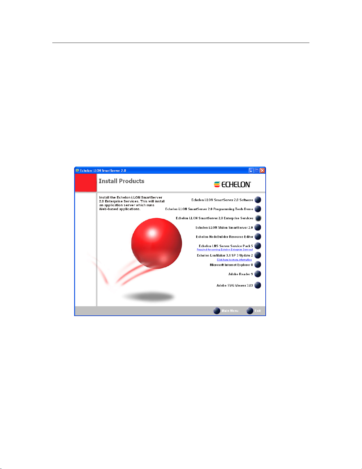
2. If the i.LON SmartServer 2.0 setup application does not launch immediately, click Start on the
taskbar and then and click Run. Browse to the setup.exe file in the root directory of the i.LON
SmartServer 2.0 DVD and click Open. The Echelon i.LON SmartServer 2.0 main menu opens.
3. Click Install Products. The Install Products dialog opens.
6 Using the Rapid Deployment Example
Page 17

4. Click Echelon i.LON SmartServer 2.0 Enterprise Services, and then follow the on- screen
instructions. See Chapter 1 of the Echelon Enterprise Services 2.0 User’s Guide for more
information on installing the EES 2.0 software.
5. After the Echelon Enterprise Services has been installed, the Tomcat 6 Server starts and an EES
tray tool (
enabled and ready for setup on your SmartServer if you are deploying the i.LON template in an
LNS managed network. For instructions on setting up and troubleshooting the LN S Proxy Web
service, see Chapter 3 of the Echelon Enterprise Services 2.0 User’ s Guide.
6. If you are deploying the i.LON template in an LNS managed network, you must also install LNS
Server Service Pack 5; otherwise, the LNS network databases on your computer may become
corrupted. To install LNS Server Service Pack 5, follow these steps:
a. Backup the LNS network databases on your computer.
b. Click the Echelon i.LON SmartServer 2.0 button in the taskbar to return to the i.LON
SmartServer 2.0 installer, click Echelon LNS Server Service Pack 5 in the Install Products
dialog, and then follow the on-screen instructions.
) is added to the notification area of your desktop. The LNS Proxy Web service is
Importing the i.LON Template
You need to import the included i.LON template into the i.LON AdminServer before you can deploy
it. To import the included i.LON template
1. Copy either the QSR-TEMPLATE-LonMaker.zip or the QSR-TEMPLATE-Standalone.zip
file from the RapidDeploymentExample folder on the root directory of the i.LON SmartServer
2.0 DVD to the L
on your computer.
ONWORKS\iLON\EnterpriseServices\repository\ees-import\templates folder
If you plan on deploying the i.LON template in an LNS managed network, copy the QSR-
TEMPLATE-LonMaker.zip file. If you plan on deploying the i.LON template in a standalone
network managed by the SmartServer, copy the QSR-TEMPLATE-Standalone.zip file.
Note: Only copy one file into the ees-import\templates folder or the import will fail.
2. Start the i.LON AdminServer. To do this, follow these steps:
Rapid Deployment Example for EES 7
Page 18

a. Open the i.LON AdminServer.
• On a local EES 2.0 client, click Start, point to Programs, point to Echelon i.LON
SmartServer 2.0 Enterprise Services, and then select i.LON SmartServer 2.0
Enterprise Administration Service.
• On a remote EES 2.0 client, open a Web browser and enter the following IPv4 address:
http://< LNS Server/EES 2.0 Computer IP
Address>/EES/AdminService/v4.0/index.htm. See Chapter 2 of the Echelon Enterprise
Services 2.0 User’s Guide for more information on accessing the i.LON AdminServer
from a remote EES 2.0 client.
b. The i.LON AdminServer home page opens.
c. Select the language to be used for the i.LON AdminServer. The i.LON AdminServer includes
English (the default), German, and French languages.
d. Click Login. A Login dialog opens.
8 Using the Rapid Deployment Example
Page 19

e. Enter the User name and Password for logging into the LNS Proxy Web service, which are
both ilon by default, and then click OK. You may have initially set the user name and
password in the EES 2.0 installer. If you cannot log into the i.LON AdminServer, use the
EES tray tool icon on your EES 2.0 computer to view the current user name and password
used for accessing the LNS Proxy Web service. See Chapter 3 of the Echelon Enterprise
Services 2.0 User’s Guide for more information on how to do this.
f. The i.LON AdminServer – Welcome Web page opens. It may take 1–2 minutes for the
i.LON AdminServer Web page to appear.
3. Right-click the Templates folder and then click Import on the shortcut menu.
4. The Import Web page opens.
Rapid Deployment Example for EES 9
Page 20

5. Click Import. It takes approximately 1-2 minutes to complete the import. When the import is
done, DONE is displayed under the Progress column.
6. You can expand the Templates icon to display the imported QSR-TEMPLATE folder, and then
expand the LAN to display the SmartServer image in the template. If you imported the QSR-
TEMPLATE-LonMaker.zip file, the QSR-TEMPLATE folder also includes an LNSProxy
icon that you can expand to view the QSR LNS network database included in the template.
Note: If you imported the wrong QSR-TEMPLATE, delete the template from the i.LON AdminServer
(right-click the QSR-TEMPLATE and click Delete on the shortcut menu), delete the backup file in
ONWORKS\iLON\EnterpriseServices\repository\ees-import\templates folder on your
the L
computer, and then follow steps 3-5 to import the other QSR-TEMPLATE.
Deploying the i.LON Template
You can deploy the i.LON template you imported in the previous section. After the i.LON template is
deployed and the target SmartServer is rebooted, the target SmartServer will automatically discover the
Neuron IDs of the uncommissioned devices on yo ur dem on s trat i on net w o r k, match the devices with
the devices defined in the deployed SmartServer or LNS network database based on program ID, and
then automatically commission the devices—all with no further user-interaction required.
To deploy the i.LON template, follow these steps:
1. If you want to preserve the current image on your SmartServer for later use, use the i.LON
AdminServer to create an i.LON project and then back up your SmartServer. For more
information on how to do this, see Chapter 2 of the Echelon Enterprise Services 2.0 User’s Guide.
2. Verify that the all L
3. Right-click the QSR-TEMPLATE folder, and then select Deploy on the shortcut menu.
10 Using the Rapid Deployment Example
ONWORKS devices on the demonstration network are uncommissioned.
Page 21

4. The Deploy Web page opens.
5. Accept all the default setting. Do not modify the default Target name, which is QSR. If you
modify the Target name, you will not be able to create a LonMaker drawing for the deployed
LNS network database.
6. Enter the following SOAP/HTTP settings for your target SmartServer:
Protocol Select the protocol used by the i.LON AdminServer to connect to the
SmartServer (HTTP or HTTPS). The selected protocol must be enabled
in the Setup - Security Web page in the SmartServer Web interface;
otherwise, the following error occurs when the i.LON AdminServer tries
to access the SmartServer: ERROR: WebService reports: "Could not
connect to i.LON SmartServer!"
• To use HTTP, the Enable Web Server check box in the Setup -
Security Web page must be selected.
• To use HTTPs, the Enable SSL Web Server check box in the Setup
- Security Web page must be selected.
Url Enter the IP address or hostname for the SmartServer to be added to the IP
channel
Port (Web
Server/SOAP)
Enter the port the SmartServer uses to serve HTTP or HTTPs requests
(SOAP and WebDAV). If you are using HTTP, the default value is 80.
If you are using HTTPs, the default value is 443. You may change the
port to any valid port number.
Rapid Deployment Example for EES 11
Page 22

Username Enter the user name for logging in to your SmartServer via HTTP. The
default user name is ilon.
Password Enter the password for logging in to your SmartServer via HTTP. The
default password is ilon.
7. Click Deploy to deploy the template. It takes approximately 25 minutes to deploy the template.
Note: You can view the status of the current deployment by entering the trace 2 command in
the target SmartServer’s console application. For more information on the SmartServer console
application, see Appendix B of the i.LON SmartServer 2.0 User’s Guide.
8. If a login dialog for the LNS Proxy Web service opens, enter the User name and Password for
logging into the LNS Proxy Web service on the target LNS Server, which are both ilon by
default, and then click OK. You may have initially set the user name and password in the EES
2.0 installer. If you cannot log into the i.LON AdminServer, use the EES tray tool icon on your
EES 2.0 computer to view the current user name and password used for accessing the LNS Proxy
Web service. See Chapter 3 of the Echelon Enterprise Services 2.0 User’s Guide for more
information on how to do this.
9. After the i.LON template has been deployed on your target SmartServer, the target SmartServer is
rebooted.
10. A new QSR project is added to the navigation pane of the i.LON AdminServer. The QSR project
contains the image of the target SmartServer, and it contains a copy of the deployed QSR LNS
network database if you imported the QSR-TEMPLATE-LonMaker.zip file. The name of the
new project and the LNS network database in the project are based on the default QSR name in
the Target property the Deploy Web page.
11. If you deployed the QSR-TEMPLATE-LonMaker.zip file, the deployment SmartServer is
synchronized to the target LNS network database.
Note: You can view the status of the synchronization by entering the trace 2 command in the
target SmartServer’s console application. For more information on the SmartServer console
application, see Appendix B of the i.LON SmartServer 2.0 User’s Guide.
12. You can open the deployment SmartServer’s Web pages and observe that the devices in the i.LON
template have been replicated and installed on the SmartServer, and observe that the network has
been synchronized to the target LNS network database (if the i.LON template included an LNS
network database).
12 Using the Rapid Deployment Example
Page 23

13. If you deployed the QSR-TEMPLATE-LonMaker.zip file, a remote network interface (RNI) for
each deployment SmartServer is automatically created in the LonWorks Interfaces Control Panel
application. The name of the RNI created is #EES#<deployment SmartServer IP address>.
14. If you deployed QSR-TEMPLATE-LonMaker.zip file, you can open the QSR LonMaker
drawing. Observe that the devices are configured, bound, and commissioned.
Rapid Deployment Example for EES 13
Page 24

Note: When you open the LonMaker drawing, a prompt may open informing that there is a NSS
device (LNS server network service device) confli ct . Click OK, and then follow the instructions
in the Network Wizard to open the drawing. Make sure you select the #EES#<deployment
SmartServer IP address> as the network interface. After the drawing is opened, a prompt opens
asking if you want to resynchronize the network. You only need to resynchronize the network if
you made changes to the network with the SmartServer before opening the LonMaker drawing.
15. If you re-deploy the QSR-TEMPLATE-LonMaker.zip file on the same LNS Server comput er
and you specify a different target name, a dialog will appear after the target SmartServer is
rebooted prompting you to manually create the LonMaker drawing associated with the deployed
LNS network database from a copy of the source QSR LNS network database. You will need
stop running EES, delete the deployed LNS network dat abase, create a copy of the source QSR
LNS network database, and name it based on the name of the deployed LNS netw or k dat a base.
For more information manually creating the LonMaker drawing in this scenario, see Chapter 2 of
the Echelon Enterprise Services 2.0 User’s Guide.
Monitoring and Controlling the Demonstration Network
After you deploy the i.LON template, you can open your SmartServer’s home page and click a link to
access the custom Web pages provided for the demonstration network. You can use these Web pages
to verify that the network is meeting corporate standards, monitor the network’s energy consumption,
control the network’s lighting and HVAC systems, and view historical and real-time data.
The Deployment Example Web pages separate energy statistics into two zones: Zone 1 includes a
Nico switch, a lamp, and the Honeywell thermostat. Zone 2 includes a Nico switch, a lamp, and the
Distech thermostat.
The following sections describe how to do the following:
1. Open the Deployment Example Web interface.
2. Use the Overview Web pages to verify that the network is meeting corporate standards, and
monitor the network’s real-time energy consumption.
3. Use the Zone Lighting Web pages to monitor and control the lighting systems in each zone on the
network.
4. Use the Zone HVAC Web pages to monitor and control the HVAC systems in each zone on the
network.
14 Using the Rapid Deployment Example
Page 25

5. Use the Power Web pages to view summaries of the energy used in each zone.
6. Use the Logs Web page to view historical energy consumption, temperature, and lighting data in
each zone.
7. You can use the Graphs Web pages to view real-time data for the energy consumption (in watts),
temperature, and lighting in each zone.
Opening the Deployment Example Web Interface
To open the deployment example Web pages, follow these steps:
1. Open your SmartServer’s home page.
2. Click the Rapid Deployment Example for EES link under the Demonstrations box.
3. The Performance Indicators Web page opens. See
for more information on using this Web page.
4. You can expand the entries in the navigation pane on left side of the Web interface and then click
a link under an entry to open a Web page. The followin g secti ons describe how to open and use
the various Deployment Example Web pages.
Using the Performance Indicators Web Page
Using the Overview Web Pages
You can use the Overview Web pages to view the network’s performance indicators and monitor the
network’s real-time energy consumption.
Using the Performance Indicators Web Page
You can use the Performance Indicators Web page to view whether the network is meeting corporate
standards. To open and use the Performance Indicators Web page, follow these steps:
1. Expand the Overview entry in the navigation pane on left side of the Web interface, and then click
Performance Indicators.
2. The Performance Indicators Web page opens.
Rapid Deployment Example for EES 15
Page 26

3. The Corporate Standard column lists the standards defined for the network to optimize its
energy savings. The goals include the lights being off after 9:00 p.m., the HVAC systems
operating only between 9:00 a.m. and 5:0 0 p. m., the temperature staying between 20° to 25°C, and
the daily power consumption being below 50 watts at 12:00 p.m.
4. The Zone 1 and Zone 2 columns displays real-time data for each zone on the network, indicating
whether the zone is meeting the standards listed under the Corporate Standard column.
Note: The top of the sidebar frame includes the number and address of a hypothetical store. If you use
the provided Web interface as a template for your custom Web pages, you need to edit the store
number and address on each deployment SmartServer to match the actual location.
Using the Power Consumption Web Page
You can use the Power Consumption Web page to monitor the network’s real-time energy
consumption. To open and use the Power Web page, follow these steps:
1. Expand the Overview entry in the navigation pane on left side of the Web interface, and then click
Power.
2. The Power Consumption Web page opens.
16 Using the Rapid Deployment Example
Page 27

3. This Web page displays the expected maximum and current power usage for each zone in the
network (in kilowatts).
Using the Zone Lighting Web Pages
You can use the Zone Lighting Web pages to monitor and control the lighting in each zone on the
network. To open and use the Zone Lighting Web pages, follow these steps:
1. Expand the Lighting entry in the navigation pane on left side of the Web interface, and then click
Zone 1 Lighting or Zone 2 Lighting.
2. The Zone Lighting Web page opens.
3. The Switch and Lamps images indicate the current state of the Nico switch and lamp in the
respective zone.
4. You can click the Switch image to turn the lamp on or off. Each time you click the Switch image,
the Lamp image is updated to show the current state of the lamp.
Note: When you click the Switch image to control the Nico switch, a green hand manual override
icon (
highest priority for writing data point values to the switch device, which means that you cannot
use the device hardware to control the switch device. To use the device hardware again to control
the switch, click the green hand icon, which temporarily resets the priority of the subject data point
on the switch device to 255.
) appears to the left of the Switch image. This indicates that the Switch image has the
Using the Zone HVAC Web Pages
You can use the Zone HVAC Web pages to monitor and control the lighting in each zone on the
network. To open and use the Zone HVAC Web pages, follow these steps:
1. Expand the HVAC entry in the navigation pane on left side of the Web interface, and then click
Zone 1 HVAC or Zone 2 HVAC.
2. The Zone HVAC Web page opens.
Rapid Deployment Example for EES 17
Page 28

3. This Web page displays the current HVAC mode, setpoint, and temperature (the setpoint and
temperature are displayed in degrees Celsius). You can use the Knob object to adjust the setpoint.
4. Optionally, you can view details of the HVAC system by clicking the Zone HVAC Details link in
the upper right-hand corner of the Web page.
5. A Web page opens displaying the current mode, occupancy state, setpoint, temperature, and status
of the HVAC system in the respective zone. The setpoint and temperature are displayed in
degrees Celsius.
6. You can manually control the HVAC system by adjusting the Mode, Occupancy, and Setpoint
properties. For example, you can turn on the hypothetical air conditioning unit for the zone by
setting the Mode property to HVAC_COOL, or you can adjust when the hypothetical air
conditioning and heating units are turned on and off by adjusting the setpoint.
18 Using the Rapid Deployment Example
Page 29

Using the Power Web Pages
You can use the Power Web pages to view summaries of the energy used in each zone. The Power
Web pages include a Power Summary Web page and a One-Line Diagram Web page. The
following sections describe these pages.
Using the Power Summary Web Page
To open and use the Power Summary Web page, follow these steps:
1. Expand the Power entry in the navigation pane on left side of the Web interface, and then click
Summary.
2. The Power Summary Web page opens.
3. This Web page includes a set of Meter objects that display the volts, amps, and kilowatts
consumed by each zone in the network.
4. Optionally, you can view details of each zone’s power consumption by clicking the Power
Summary Table link in the upper right-hand corner of the Web page.
5. A Web page opens displaying a table that lists the volts, amps, and kilowatts consumed by each
zone in the network.
Rapid Deployment Example for EES 19
Page 30

Using the One-Line Diagram Web Page
To open and use the One-Line Diagram Web page, follow these steps:
1. Expand the Power entry in the navigation pane on left side of the Web interface, and then click
One-Line Diagram.
2. The Power Web page opens.
3. This Web page displays a VU Meter image for each zone that indicates the zone’s energy
consumption in watts.
Using the Logs Web Pages
You can use the Logs Web pages to view a graph and a log that provide historical tracking of the
energy consumption (in watts), temperature, and lighting data in the selected zone. To open and use
the Logs Web pages, follow these steps:
1. Expand the Logs entry in the navigation pane on left side of the Web interface, and then click
Power, HVAC, or Lighting.
2. The Logs Web page opens.
20 Using the Rapid Deployment Example
Page 31

3. This Web page displays a trend graph and a log that chart and list the energy consumption (in
watts), temperature, or lighting state for the selected zone over a specific interval. Note that the
trend graph only appears if Adobe SVG Viewer 3.03 is installed on your computer. If Adobe
SVG Viewer is not installed on your computer, a Show Graph link appears where the graph
normally would. You can install Adobe SVG Viewer 3.03 from the i.LON SmartServer 2.0 DVD.
4. You can move the mouse pointer over one of the plotted data point updates to show a ToolTip.
The ToolTip lists the date and time of the update and the value and state of the data point at the
time the update was recorded.
5. The table lists the first to last recorded data point updates in descending chronological order. You
can sort the data point updates by clicking a property header. This Web page displays the
following properties for each recorded data point update:
Selected Time
Interval
Displays the user-specified interval, which determines the data points
currently shown on the Web page. The default interval is the time from the
first to last data point recorded by the data loggers on your SmartServer.
• Click Clear Log Interval to clear the currently selected range of data
points from the Web page. Note that the Web page only shows the first
60 entries in the range, but the entire range will be deleted.
• Click Clear Entire Log to clear all the selected data points from the
Web page.
Time Displays the date and time when the data point update occurred.
Name Displays the name of the data point that was updated using the following
format: <network>/<channel>/<device>/<functional block>/<data point>.
Rapid Deployment Example for EES 21
Page 32

Value Displays the value of the data point at the time of the update. If a preset is
defined for the data point value, the preset name will be displayed instead of
the actual value.
Unit Displays the unit string of the data point.
Status Displays the status of the data point at the time of the update.
In some cases, there may be more log entries within the selected range than can be displayed on
the screen at once. In this case, a warning message will be displayed, and you can use the slide
bar to browse the log entries.
6. You can use the slide bar at the top to browse the first to last updates recorded for the selected data
point. Move the slider bar to the left to display older sets of values, or move it to the right to
display the more recent values. If there a re too many values within the selected range to be
displayed, a warning message appears informing you that only a subset of the data points is being
displayed.
7. You can specify the time interval for which recorded data point updates are listed in the log and
displayed in the trend graph using the drop-down list directly below the slider. The default is
Entire Range, which means that the log lists the first to last data point updates recorded in the
data loggers on the SmartServer and the trend graph plots the first to last updates recorded for a
selected data point.
Note: If you use the provided Web interface as a template for your custom Web pages, you need to
open the Data Logger Web pages (logs_HVAC.htm, logs_Lighting.htm, and logs_Power.htm) on
each deployment SmartServer and update the selected Data Logger in the Data Logger properties
dialog. This is because the name of the selected Data Logger on the deployment SmartServer will be
different from the one specified in the i.LON template.
Using the Graphs Web Pages
You can use the Graphs Web pages to view real-time trend graphs for the energy consumption (in
watts), temperature, and lighting in the selected zone. To open and use the Graphs Web pages, follow
these steps:
1. Expand the Graphs entry in the navigation pane on left side of the Web interface, and then click
Power, HVAC, or Lighting.
2. The Graphs Web page opens.
22 Using the Rapid Deployment Example
Page 33

3. This Web page displays a real-time trend graph that charts the energy consumption (in watts),
temperature, or lighting state in the selected zone.
Rapid Deployment Example for EES 23
Page 34

www.echelon.com
 Loading...