

Page 1

OpenLNS Commissioning Tool
User's Guide
078-0488-01A
Page 2

Echelon, LON, LONWORKS, LonTalk, Neuron,
LONMARK, 3120, 3150, LNS, LonMaker, and
the Echelon logo are trademarks of Echelon
Corporation registered in the United States
and other countries. LonSupport is a
trademark of Echelon Corporation.
Other brand and product names are trademarks or
registered trademarks of their respective holders.
Neuron
Chips and other OEM Products were not
designed for use in equipment or systems which involve
danger to human health or safety or a risk of property
damage and Echelon assumes no responsibility or
liability for use of the Neuron
Chips in such applications.
Parts manufactured by vendors other than Echelon and
referenced in this document have been described for
illustrative purposes only, and may not have been tested
by Echelon. It is the responsibility of the customer to
determine the suitability of these parts for each
application.
ECHELON MAKES NO REPRESENTATION, WARRANTY, OR
CONDITION OF ANY KIND, EXPRESS, IMPLIED, STATUTORY,
OR OTHERWISE OR IN ANY COMMUNICATION WITH YOU,
INCLUDING, BUT NOT LIMITED TO, ANY IMPLIED
WARRANTIES OF MERCHANTABILITY, SATISFACTORY
QUALITY, FITNESS FOR ANY PARTICULAR PURPOSE,
NONINFRINGEMENT, AND THEIR EQUIVALENTS.
No part of this publication may be reproduced, stored in
a retrieval system, or transmitted, in any form or by any
means, electronic, mechanical, photocopying,
recording, or otherwise, without the prior written
permission of Echelon Corporation.
Printed in the United States of America.
Copyright ©1997–2012 by Echelon
Corporation.
Echelon Corporation
www.echelon.com
ii Preface
Page 3

Table of Contents
Preface .................................................................................................... xi
Purpose ..........................................................................................................xii
Audience.........................................................................................................xii
System Requirements....................................................................................xii
OpenLNS CT Documentation.........................................................................xii
For More Information and Technical Support................................................xiii
Content..........................................................................................................xv
1 Introduction ....................................................................................... 1
Introduction to the OpenLNS Commissioning Tool.........................................2
New Features ..................................................................................................2
No-Cost Device Installation.......................................................................2
Automated Product Activation...................................................................3
Annual Product Maintenance....................................................................3
Increased Device Compatibility.................................................................3
Longer Database Directory Paths.............................................................3
Improved Windows Compatibility..............................................................3
Additional OpenLNS Events .....................................................................3
New OpenLNS CT Menus ........................................................................3
OpenLNS CT Versions....................................................................................4
OpenLNS CT Network Designs.......................................................................4
OpenLNS Network Database....................................................................4
OpenLNS CT Drawing ..............................................................................5
LONWORKS Basics ...........................................................................................5
Networks...................................................................................................5
Devices .....................................................................................................5
Protocol.....................................................................................................5
Device Templates .....................................................................................5
Channels...................................................................................................5
Routers......................................................................................................6
Applications...............................................................................................6
Network Variables.....................................................................................6
Configuration Properties...........................................................................7
Functional Blocks......................................................................................7
Functional Profiles.....................................................................................7
Standard Network Variable and Configuration Property
Types..................................................................................................
User-defined Standard Network Variable and Configuration Property
Types..................................................................................................
Subsystems...............................................................................................8
Supernodes...............................................................................................9
Visio Basics .....................................................................................................9
8
8
2 Installing and Activating OpenLNS CT.......................................... 11
Ordering OpenLNS CT..................................................................................12
Installing and Activating OpenLNS CT..........................................................12
Manually Activating OpenLNS CT.................................................................19
3 Getting Started ................................................................................ 25
Design Overview ...........................................................................................26
Defining Network Requirements and Organization.................................26
Selecting a Network Installation Scenario ..............................................26
Engineered System Scenario...........................................................26
OpenLNS CT User’s Guide iii
Page 4

Ad-Hoc System Scenario .................................................................27
Determining User Permissions ...............................................................27
Optimizing OpenLNS CT Network Performance ....................................27
Drawing Files....................................................................................27
Network Changes.............................................................................28
Connections......................................................................................28
Sharing the OpenLNS Interface with the LNS DDE Server .............28
Functional Blocks .............................................................................28
Subsystems......................................................................................29
OpenLNS CT Design Manager Overview .....................................................29
Options....................................................................................................32
New Network Options.............................................................................34
OpenLNS CT Stencils.............................................................................36
OpenLNS CT Default Options.................................................................37
Setting Up a Network Interface......................................................................38
Optimizing Network Interface Performance............................................38
Using an IP-852 Network Interface.........................................................38
Creating and Opening OpenLNS CT Networks.............................................40
Creating an OpenLNS CT Network Design............................................40
Working with Digital Signatures........................................................46
Creating an OpenLNS CT Network from an Existing OpenLNS
Database..................................................................................................
Copying an OpenLNS CT Network Design.............................................51
Opening an OpenLNS CT Network Design............................................53
OpenLNS CT Client Types .....................................................................55
Local Client.......................................................................................55
Remote Full Client............................................................................56
Remote Lightweight Client................................................................60
Using Network Service Device SmartShapes...............................................63
Listing Network Service Devices......................................................64
Upgrading Network Service Devices................................................65
Replacing a Local Network Service Device......................................66
User Profiles..................................................................................................66
Creating a New User Profile ...................................................................67
Changing Passwords..............................................................................69
Modifying and Deleting User Profiles......................................................70
Changing User Profiles in an OpenLNS CT Drawing.............................70
Using OpenLNS CT Remotely with User Profiles...................................71
47
4 Designing Networks........................................................................ 73
Creating a LONWORKS Network.....................................................................74
Creating an OpenLNS CT Drawing...............................................................74
Creating Application Devices..................................................................75
Using Automatic Channel Selection for Devices..............................79
Changing the Channel of an Application Device..............................80
Creating Functional Blocks.....................................................................81
Using Automatic Device Selection ...................................................85
Reassigning a Functional Block .......................................................85
Configuring a Functional Block.........................................................86
Copying a Functional Block Configuration .......................................86
Creating a New Functional Block from a Configured
Functional Block.........................................................................
Updating a Functional Block from a Configured Functional
Block ..........................................................................................
Creating a Functional Block Master SmartShape ............................89
Creating Dynamic Functional Blocks................................................89
iv Preface
86
86
Page 5

Deleting Dynamic FBs ...............................................................91
Creating Dynamic Functional Block Master SmartShapes........91
Creating a Virtual Functional Block..................................................91
Adding a Message Tag SmartShape to a Virtual Functional
Block ..........................................................................................
Deleting Message Tag SmartShapes........................................92
Creating Network Variables....................................................................92
Creating a Network Variable SmartShape .......................................93
Creating a Network Variable Master SmartShape...........................93
Adding Network Variable SmartShapes to a Functional Block ........93
Creating Network Variables Using Generic Network
Variable SmartShapes...............................................................
Creating Dynamic Network Variables Using Network
Variables SmartShapes from the OpenLNS CT NV
SmartShapes Stencil .................................................................
Creating Dynamic Network Variables Using Network
Variable Master SmartShapes...................................................
Changing a Network Variable Name................................................99
Changing Network Variable Position................................................99
Deleting a Network Variable SmartShape........................................99
Deleting Dynamic Network Variables.............................................101
Creating a Router........................................................................................101
Using Automatic Channel Selection for Routers............................105
Changing a Router Channel...........................................................106
Creating a Channel......................................................................................106
Creating a Subsystem.................................................................................108
Creating a Supernode...........................................................................110
Renaming and Deleting a Supernode Network Variable......................111
Copying a Subsystem or Supernode....................................................111
Creating Connections..................................................................................112
Creating a Connection with the Connector SmartShape......................113
Creating a Connection with the Connector Tool...................................113
Creating a Connection with the Network Variable Connection
Dialog Box.............................................................................................
Using Reference Connection SmartShapes.........................................117
Aligning Reference Connection SmartShapes...............................117
Using Connection Descriptions.............................................................118
Connection Description Properties.................................................118
Message Service Type ............................................................118
Addressing Mode.....................................................................119
Viewing and Creating Connection Descriptions.............................119
Using Automatic Connection Description Selection.......................121
Changing the Connection Description for a Connection................123
Hiding and Showing Connector SmartShapes .....................................124
Hiding and Showing All Connector SmartShapes in a
Subsystem......................................................................................
Hiding and Showing Selected Connector SmartShapes
Attached to Functional Blocks or Supernodes ...............................
Hiding and Showing Connector SmartShapes Attached
to a Functional Block......................................................................
Viewing and Navigating OpenLNS CT Network Design..............................128
Opening any Subsystem ................................................................128
Opening a Parent Subsystem ........................................................129
Using Network Navigators..............................................................129
Navigating and Managing a Network with the Network Explorer..........130
Navigating a Network with the Network Explorer...........................132
92
94
98
98
114
124
124
126
OpenLNS CT User’s Guide v
Page 6

Managing a Network with the Network Explorer............................132
Managing and Editing Device Templates with the Network
Explorer ..........................................................................................
Managing Device Templates ...................................................132
Editing Device Template Properties.........................................133
Working with OpenLNS CT Layers .............................................................135
Working with OpenLNS CT SmartShapes ..................................................136
Viewing and Setting OpenLNS CT SmartShape Properties.................136
Moving an OpenLNS CT SmartShape..................................................136
Repositioning an OpenLNS CT SmartShape.................................136
Changing the Subsystem for an OpenLNS CT SmartShape.........136
Changing the Channel for an OpenLNS CT SmartShape..............137
Moving a Device or Router to a Different Channel..................137
Moving an OpenLNS Computer to a Different Channel...........139
Copying an OpenLNS CT SmartShape................................................140
Deleting an OpenLNS CT SmartShape................................................140
Customizing the User Interface...................................................................141
Editing the Title Block ...........................................................................141
Using OpenLNS CT SmartShape Menus .............................................141
Using AutoCAD Drawings ...........................................................................142
Importing an AutoCAD Drawing............................................................142
Exporting an AutoCAD Drawing............................................................143
132
5 Installing Networks ....................................................................... 145
Network Installation Overview.....................................................................146
Commissioning a Device.............................................................................146
Selecting Devices for Commissioning...................................................147
Loading a Device Application Image.....................................................148
Setting the Initial Device State and Source of Configuration
Property Values.....................................................................................
Setting the Initial Application Device State and Source of
Con f i g u ra t i o n P r op e r t y V a lu e s...........................................................
Setting the Initial Router State........................................................153
Setting the Neuron ID ...........................................................................154
Selecting the Device Identification Method ....................................154
Using the Service Pin Method........................................................155
Using the Manual Entry Method.....................................................157
Entering a Neuron ID Manually................................................157
Entering a Neuron ID Using a Bar Code Scanner...................157
Commissioning an IP-852 Router ...............................................................158
Commissioning Using Device Discovery.....................................................158
150
151
6 Monitoring and Controlling Networks......................................... 165
Monitoring and Controlling Overview ..........................................................166
Using Monitored Connections .....................................................................166
Displaying a Network Variable Value....................................................167
Using the OpenLNS CT Browser ................................................................168
Starting the OpenLNS CT Browser.......................................................168
The OpenLNS CT Browser Toolbar......................................................170
Customizing the Browser......................................................................170
Customizing Browser Columns ......................................................171
Hiding or Changing the Order of Browser Columns ................171
Adjusting the Width of Browser Columns ................................171
Customizing Browser Rows............................................................171
Selecting Browser Rows to be Displayed................................171
Hiding Browser Rows...............................................................172
vi Preface
Page 7

Saving Browser Customization ......................................................173
Monitoring Network Variables...............................................................173
Enabling Network Variable Monitoring...........................................173
Disabling Network Variable Monitoring ..........................................173
Getting Network Variable Values ...................................................173
Using Bound Updates...........................................................................174
Binding Network Variables to the Host .................................................174
Updating Network Variable and Configuration Property Values...........175
Setting Values ................................................................................175
Setting Values for Structured Objects......................................175
Setting Values for Configuration Property Arrays....................177
Clearing Values..............................................................................178
Getting Values................................................................................178
Changing a Network Variable or Configuration Property Type.............178
Changing a Network Variable or Configuration Property Format.........179
Displaying Error Messages...................................................................181
Managing Functional Blocks.................................................................181
Using Data Point SmartShapes...................................................................182
Adding and Monitoring a Data Point SmartShape................................182
Updating a Data Point...........................................................................185
Updating a Scalar Data Point.........................................................186
Updating a Structured Data Point...................................................186
Updating an Enumerated Data Point..............................................187
Getting a Data Point Value ...................................................................187
Creating and Using a Custom Data Point Master SmartShape............188
Creating a Custom Data Point Master SmartShape ......................188
Using a Custom Data Point Master SmartShape...........................188
Copying and Creating a Data Point SmartShape.................................189
Deleting a Data Point SmartShape.......................................................189
Creating an HMI with Data Point SmartShapes....................................189
Writing Data Point SmartShape Values .........................................190
Using an Add-On to Write Values............................................190
Using a Macro to Write Values ................................................191
Reading Data Point SmartShape Values.......................................192
Using an Add-On to Read Values............................................192
Using a Macro to Read Values................................................193
Organizing HMIs.............................................................................194
7 Maintaining Networks................................................................... 195
Maintaining Networks Overview..................................................................196
Loading Devices..........................................................................................196
Selecting the Devices to Load ..............................................................197
Selecting or Creating a Device Template .............................................197
Selecting an Application Image and a Neuron Firmware Image ..........198
Selecting Initial Device State and Source of Configuration
Property Values.....................................................................................
Replacing Devices.......................................................................................202
Attaching a New Device to the Network................................................202
Replacing a Device in the OpenLNS CT Network................................202
Removing the Old Device.....................................................................205
Decommissioning Devices ..........................................................................205
Resynchronizing Configuration Properties..................................................205
Using OpenLNS CT as a Passive Configuration Tool.................................207
Backing up an OpenLNS CT Network Design.............................................207
Manually Backing Up an OpenLNS CT Network..................................208
Creating a Backup from an OpenLNS CT Drawing........................208
OpenLNS CT User’s Guide vii
200
Page 8

Creating a Backup from the OpenLNS CT Design Manager .........210
Scheduling Drawing Saves and Database Backups.............................210
Scheduling Backups with OpenLNS CT ..................................210
Scheduling Backups with the Windows Task Scheduler.........212
Restoring an OpenLNS CT Network.....................................................214
Restoring a Network Database Backup .........................................214
Restoring an OpenLNS CT Drawing Backup.................................216
Restoring a Full Network Backup...................................................217
Recovering an OpenLNS CT Network ........................................................221
Subsystem Recovery Options...............................................................222
Using Subsystem Paths .................................................................224
Using Subsystem IDs.....................................................................224
Using the OpenLNS Database Recovery Wizard.................................225
Network Recovery vs. Database Backup ............................................234
Resynchronizing an OpenLNS CT Network................................................235
Automatic OpenLNS CT Drawing Synchronization ..............................235
OpenLNS Event Tracking...............................................................236
OpenLNS CT Event Log.................................................................236
Viewing the OpenLNS CT Event Log ......................................236
Exporting the OpenLNS CT Event Log....................................237
Manual Network Resynchronization .....................................................239
Refreshing the OpenLNS CT Network..................................................247
Merging OpenLNS CT Networks.................................................................247
Network Merge Considerations.............................................................248
Limitations ......................................................................................248
Information Loss.............................................................................248
Merging OpenLNS CT Networks ..........................................................249
8 Managing Networks ...................................................................... 253
Using the OpenLNS CT Device Manager ...................................................254
Opening the OpenLNS CT Device Manager ........................................254
Managing Devices.................................................................................255
Managing Functional Blocks.................................................................256
Managing Routers.................................................................................258
Device Manager Settings......................................................................259
Using OpenLNS CT Styles Overview..........................................................260
OpenLNS CT Device Styles..................................................................260
OpenLNS CT Functional Block Styles..................................................261
Network Variable and Message Tag SmartShape Styles.....................263
OpenLNS CT Connector SmartShape Styles.......................................263
Generating a Device Status Summary Report............................................264
Using Resource Usage Reports..................................................................267
Network Resource Report.....................................................................267
Alias Table Summary............................................................................268
9 Exporting and Importing Networks with XML............................ 271
Using XML Export/Import Overview ............................................................272
Exporting a LONWORKS Network XML File ...........................................272
Viewing an OpenLNS CT Network Report............................................274
Importing a LONWORKS Network XML File............................................277
10 Managing OpenLNS CT Licenses................................................ 279
Commissioning Devices with OpenLNS CT................................................280
Overview of OpenLNS CT Licensing...........................................................280
Maintaining OpenLNS CT............................................................................280
viii Preface
Page 9

Upgrading OpenLNS CT Standard Edition to OpenLNS CT
Professional Edition.....................................................................................
Renewing OpenLNS CT Annual Maintenance............................................289
Transferring OpenLNS CT Licenses ...........................................................289
286
11 Using Plug-ins ............................................................................... 293
Using Plug-ins Overview .............................................................................294
Starting a Plug-in.........................................................................................294
Viewing Plug-in Information.........................................................................296
Viewing Plug-in Status.................................................................................297
Re-Registering Plug-ins...............................................................................298
Disabling and Enabling Plug-ins..................................................................299
Disabling a Plug-in................................................................................299
Enabling a Plug-in.................................................................................299
12 Creating and Using Custom OpenLNS CT SmartShapes
and Stencils...................................................................................
OpenLNS CT Stencils .................................................................................302
Creating a Custom OpenLNS CT Stencil....................................................302
Creating Custom OpenLNS CT Master SmartShapes................................303
Using Custom OpenLNS CT Master SmartShapes....................................304
Device Master SmartShapes................................................................304
Functional Block Master SmartShapes.................................................305
Subsystem or Supernode Master SmartShapes ..................................305
Connection Master SmartShapes.........................................................306
Creating Additional Channels ...............................................................308
Editing Master SmartShape User Defined Cells .........................................308
Additional Device User Cells.................................................................309
Additional Functional Block User Cells.................................................314
Additional Router SmartShape User Cells............................................315
Setting User Functional Block Scopes and Types ......................................315
Adding a Bitmap to a Device Master SmartShape......................................315
Viewing and Editing VBA Code Associated with an OpenLNS CT
Network Drawing.........................................................................................
301
316
Appendix A Setting OpenLNS CT Default Options.......................... 317
Setting OpenLNS CT Default Options.........................................................318
Backup/Restore Options.......................................................................319
Configuration Properties Options..........................................................322
Device Options......................................................................................325
Functional Block Options ......................................................................327
General Options....................................................................................330
OpenLNS Event Options.......................................................................331
Naming Options ....................................................................................333
Network Explorer Options.....................................................................335
NV Browser/Monitoring Options............................................................336
OpenLNS CT Font Options...................................................................337
Recovery Options..................................................................................338
Service Pin Options...............................................................................341
Shape ToolTips Options .......................................................................342
Synchronization Options.......................................................................343
Warnings Options..................................................................................344
Appendix B Glossary......................................................................... 347
Appendix C OpenLNS Software License Agreement...................... 367
OpenLNS CT User’s Guide ix
Page 10

Appendix D Software License Transfer Agreement........................ 375
x Preface
Page 11

Preface
The OpenLNS Commissioning Tool (OpenLNS CT) is a software package for
designing, installing, and maintaining multi-vendor, open, interoperable L
control networks. Based on Echelon's OpenLNS network operating system,
OpenLNS CT combines support for open LONWORKS control networks with a
user-friendly Microsoft Visio interface. The result is a software tool that’s robust
enough to work with all your devices, yet economical enough to leave behind as an
operations and maintenance tool. OpenLNS CT, OpenLNS Server, and the OpenLNS
SDK are the three primary components of OpenLNS. OpenLNS CT complies with
the OpenLNS plug-in standard, and it is compatible with the LNS plug-in standard,
making it compatible with the wide variety of plug-ins available from Echelon and
many other vendors.
ONWORKS
®
OpenLNS CT User’s Guide xi
Page 12

Purpose
This guide outlines the new features in the OpenLNS Commissioning Tool (OpenLNS CT), and it
describes how to use OpenLNS CT to design, commission, monitor and control, maintain, and manage
a network. OpenLNS CT includes online help that provides context-sensitive documentation that
supplements the information in this guide.
Audience
This guide is intended for system designers and integrators with an understanding of control networks.
System Requirements
System requirements for computers running the OpenLNS CT are as follows:
• Microsoft Windows
with Service Pack (SP) 1, or Windows XP with SP3 (32-bit).
• 500 MHz processor or faster. 2 GHz processor recommended.
• 2 GB or more of free disk space.
• 512 MB RAM. 2 GB RAM recommended.
®
7 (64-bit and 32-bit), Windows Server 2008 SR2 64-bit, Windows Vista®
• 1,024 MB page file minimum. 2,048 page file recommended.
• 1,024 x 768 or higher-resolution display with at least 256 colors.
• Mouse or compatible pointing device
• DVD-ROM drive.
• OpenLDV 4.0-compatible local, remote, or IP-852 network interface.
o Compatible local network interfaces include the U10/U20 USB network interface; PCC-10,
PCLTA-20, or PCLTA-21 network interface cards; and the SLTA-10 Serial LonTalk Adapter.
The PCC/PCLTA and SLTA-10 network interfaces are compatible with 32-bit versions of
Windows only.
o Compatible remote network interfaces include the SmartServer, i.LON 100 Internet Server,
i.LON 600 IP-852 Router, and i.LON 10 Ethernet Adapter.
o Compatible IP-852 network interfaces include the SmartServer (with IP-852 routing option),
i.LON 100 Internet Server (with IP-852 routing option), and i.LON 600 IP-852 Router.
OpenLNS CT Documentation
The documentation for OpenLNS CT is provi de d as Adobe Acrobat PDF files and online help files.
The PDF file for this document is installed in the Echelon OpenLNS CT program folder when you
install the Echelon OpenLNS CT software. You can also download the latest OpenLNS
documentation, including the latest version of this guide, by going to the Echelon OpenLNS Web site
www.echelon.com/openlns.
at
OpenLNS CT XML Programmer’s
Guide
OpenLNS Programmer’s Guide
xii Preface
Describes how to create and modify an OpenLNS network using
the OpenLNS XML Plug-in.
Describes how to use the OpenLNS Object Server ActiveX
Control to develop OpenLNS apps.
Page 13

OpenLNS Programmer’s Reference Provides reference information for writing OpenLNS tools,
applications, and plug-ins. Describes the objects in the
OpenLNS Object hierarchy, and details their properties,
methods, and events.
®
Plug-in Framework Developer’s
LNS
Guide
Describes how to write system and device plug-ins using .NET
programming languages such as C# and Visual Basic .NET.
The following documents supplement the material provided in this guide. You can download th ese
documents from Echelon’s Web site at
www.echelon.com/docs.
i.LON 600 LonWorks/IP Server User's
Guide
Introduction to the L
ONWORKS
®
Platform
Describes how to install, configure, use, and manage the i.LON
600 IP-852 routers, and how to use the Echelon IP-852
Configuration Server.
Provides a high-level introduction to L
ONWORKS networks and
the tools and components that are used for developing, installing,
operating, and maintaining them.
IP-852 Channel User’s Guide Describes how to configure an IP-852 channel with the Echelon
IP-852 Configuration Server. You will need this information if
you plan on attaching your OpenLNS CT computer to an IP-852
channel.
ONMARK
L
®
SNVT and SCPT Guide
Documents the standard network variable types (SNVTs) and
standard configuration property types (SCPTs) used by
ONWORKS device applications. For more information, go the
L
ONMARK International Web site at
L
www.lonmark.org/technical_resources/resource_files.
L
ONWORKS
®
User’s Guide
USB Network Interface
Describes how to install and use the U10 and U20 USB Network
Interfaces to connect an OpenLNS or OpenLDV application to a
ONWORKS network.
L
Mini FX User’s Guide Describes how to use the Mini kit to develop a prototype or
production control system that requires networking, particularly
in the rapidly growing, price-sensitive mass markets of smart
light switches, thermostats, and other simple devices and sensors.
NodeBuilder
®
FX User’s Guide
Describes how to use the NodeBuilder tool to develop
ONWORKS device applications and build and test prototype and
L
production L
ONWORKS devices
PCC/PCLTA Network Interface User's
Guide
Describes how to install, configure, and test the PCC-10,
PCLTA-20, and PCLTA-21 network interface cards that you can
use to connect an OpenLNS or OpenLDV application to a
ONWORKS network.
L
SmartServer 2.0 User’s Guide Describes how to configure the SmartServer and use its
applications to manage control networks.
For More Information and Technical Support
The Echelon OpenLNS CT ReadMe document provides descriptions of known problems, if any, and
their workarounds. To view the Echelon OpenLNS CT ReadMe document, clic k Start, point to
Programs, point to Echelon OpenLNS CT, and then select Echelon OpenLNS CT ReadMe.
If you have technical questions that are not answered by this document, the OpenLNS CT online help
files, or the Echelon OpenLNS CT ReadMe document, you can contact Echelon technical support.
There is no charge for software installation-related questions during the first 30 days after you receive
OpenLNS CT User’s Guide xiii
Page 14

the OpenLNS CT DVD or purchase an OpenLNS CT activation key. To receive technical support
from Echelon, you must purchase support services from Echelon or an Echelon support partner. See
www.echelon.com/support for more information on Echelon support. Your OpenLNS CT distributor
may also provide customer support.
You can also enroll in training classes at Echelon or an Echelon training center to learn more about
using OpenLNS CT. You can find additional information about device development training at
www.echelon.com/training.
You can obtain technical support via phone, fax, or e-mail from your closest Echelon support center.
The contact information is as follows:
Region Languages Supported Contact Information
The Americas
English
Japanese
Echelon Corporation
Attn. Customer Support
550 Meridian Avenue
San Jose, CA 95126
Phone (toll-free):
1.800-258-4LON (258-4566)
Phone: +1.408-938-5200
Fax: +1.408-790-3801
lonsupport@echelon.com
Europe
Japan
China
English
German
French
Italian
Echelon Europe Ltd.
Suite 12
Building 6
Croxley Green Business Park
Hatters Lane
Watford
Hertfordshire WD18 8YH
United Kingdom
Phone: +44 (0)1923 430200
Fax: +44 (0)1923 430300
lonsupport@echelon.co.uk
Japanese Echelon Japan
Holland Hills Mori Tower, 18F
5-11.2 Toranomon, Minato-ku
Tokyo 105-0001
Japan
Phone: +81.3-5733-3320
Fax: +81.3-5733-3321
lonsupport@echelon.co.jp
Chinese
English
Echelon Greater China
Rm. 1007-1008, IBM Tower
Pacific Century Place
2A Gong Ti Bei Lu
Chaoyang District
Beijing 100027, China
Phone: +86-10-6539-3750
Fax: +86-10-6539-3754
lonsupport@echelon.com.cn
Other Regions
English
Japanese
Phone: +1.408-938-5200
Fax: +1.408-328-3801
lonsupport@echelon.com
xiv Preface
Page 15

Content
This guide includes the following content:
•
Introduction: Provides an introduction to the OpenLNS CT, new features; and the basics of
OpenLNS CT network designs, L
•
Installing and Activating OpenLNS CT: Describes how to order and install OpenLNS CT and
Microsoft Visio 2010, and then how to activate OpenLNS CT.
•
Getting Started: Provides information on the planning an OpenLNS CT network design; using the
OpenLNS CT Design Manager; setting up a network interface; creating and opening an OpenLNS
CT network design; OpenLNS CT client types; using OpenLNS CT remotely; and creating and
using user profiles.
Designing Networks: Describes how to design a netwo r k usi n g OpenLNS CT. Covers how to
•
create the following objects in an OpenLNS CT drawing: application devices, functional blocks,
network variables, routers, channels, and subsystems. Explains how to connect network variables.
Explains working with OpenLNS CT SmartShapes
user interface, and using OpenLNS CT with AutoCAD drawings.
•
Installing Networks: Describes how to install devices using OpenLNS CT, including how to load
applications into them, set the initial state of their applications, set the source of their
configuration properties, and select how they manage device-specific configuration properties. It
also explains the different methods for acquiring device Neuron IDs and how to alternatively use
the device discovery method to install a network.
ONWORKS, and Visio.
®
and layers, customizing the OpenLNS CT
Monitoring and Controlling Netw orks: Describes how you can monitor and control the devices in
•
your network with OpenLNS CT. Describes the three methods you can use to read and/or write
network variables and configuration properties: using monitored connections, browsing with the
OpenLNS CT Browser, and using Data Point SmartShapes. Covers how to bind network variables
to the host in order to receive event-driven updates. Describes how to change the types and
formats of network variables and configuration properties. Explains how to create simple HMIs in
your OpenLNS CT drawing with Data Point and Visio SmartShapes.
Maintaining Networks: Provides an overview of network maintenance tasks that you can perform
•
with OpenLNS CT. Describes loading, repla ci ng, and decommissioning devices. Explains how to
resynchronize and propagate configuration properties values. Explains how to back up and restore
an OpenLNS CT network; create an OpenLNS CT network by recovering information from the
physical network; and resynchronize the network database, OpenLNS CT drawing, and physical
devices. Explains how to merge two OpenLNS CT networks.
Managing Networks: Explains how to test and verify application devices, functional blocks, and
•
routers; describes OpenLNS CT styles; and details how to generate device status summary reports,
network resource reports, and OpenLNS network reports.
Managing OpenLNS CT Licenses: Provides an overview of OpenLNS CT licensing. Describes
•
how to upgrade OpenLNS CT, upgrade an OpenLNS CT Standard Edition to the Professional
Edition, renew your OpenLNS CT annual maintenance contract, and transfer an OpenLNS CT
license.
Exporting and Importing a Network Using XML: Describes how to export a LONWORKS network
•
to an OpenLNS CT network XML file; view a LONWORKS network XML file in a Web
browser; edit an OpenLNS CT network XML file; and import a LONWORKS network XML file
to update a network.
Using Plug-ins: Provides an overview of plug-ins and then describes how to start a plug-in, get
•
plug-in information, and re-register, enable, and disable plug-ins.
OpenLNS CT User’s Guide xv
Page 16

Creating and Using OpenLNS CT SmartShapes and Stencils: Describes how to create an
•
OpenLNS CT stencil and create and use custom master SmartShapes for devices, functional
blocks, subsystems, and connections. Explains how to modify a master SmartShape by changing
its user-defined cells.
• Appendices: Includes the OpenLNS CT default options, a glossary, the OpenLNS CT Software
License Agreement, and the OpenLNS CT License Transfer Agreement.
xvi Preface
Page 17

1
Introduction
This chapter provides an introduction to the OpenLNS Commissioning Tool, describes
new features, and explains the basics of OpenLNS CT Network Designs, L
ONWORKS,
and Visio.
OpenLNS CT User’s Guide 1
Page 18

Introduction to the OpenLNS Commissioning Tool
The OpenLNS Commissioning Tool (OpenLNS CT) is a LONWORKS® network tool that runs on the
OpenLNS network operating system and uses Microsoft Visio
Standard editions) as a graphical user interface. The OpenLNS network operating system implements
a client/server architecture with directory, installation, management, monitoring, and control services
provided by an OpenLNS Server that is included with the OpenLNS CT. The OpenLNS Server
allows multiple users running OpenLNS CT and other OpenLNS tools, applications, and plug-ins on
separate computers to access the OpenLNS Server simultaneously. This means that managers, system
integrators, installers, and maintenance personnel can all work on the same L
same time. OpenLNS CT is compatible with Windows 7 (64-bit and 32-bit), Windows Server 2008 R2
(64-bit), Windows Vista with SP1 (32-bit), and Windows XP with SP3 (32-bit). The OpenLNS Server
and OpenLNS CT are backwards compatible with all existing LNS Turbo Edition databases and
LonMaker Turbo Edition drawings providing simple migration for existing LNS and LonMaker
networks.
OpenLNS CT can be used to manage all phases of a network’s life cycle—from the initial design and
commissioning to the ongoing operation. It provides the functionality of several network tools in one
single solution:
• Network Design Tool. You can design a network offsite (without actually being connected to the
network) and/or onsite, and modify it anytime.
• Network Installation Tool. You can rapidly install a network designed offsite once it is brought
onsite. The device definitions can be quickly and easily associated with their corresponding
physical devices to reduce on-site commissioning time. The OpenLNS CT Browser provides
complete access to all network variables and configuration properties.
• Network Documentation Tool. You can create an OpenLNS CT drawing during the network
design and installation process. This OpenLNS CT drawing is an accurate, logical representation
of the installed physical network. The OpenLNS CT drawing is therefore an essential component
of as-built reports.
®
2010 or Visio 2003 (Professional or
ONWORKS network at the
• Network Operation Tool. You can operate the net w or k using the operator interface pages
contained within the OpenLNS CT drawing.
• Network Maintenance Tool. You can easily add, test, remove, modify, or replace devices, routers,
channels, subsystems, and connections to maintain the network.
New Features
This section describes the major features included with the OpenLNS Server and OpenLNS CT.
•
No-cost device installation.
Automated product activation (Internet connection required).
•
Annual product maintenance.
•
Increased device compatibility.
•
Longer database directory paths.
•
Improved Microsoft Windows® Compatibility.
•
Additional OpenLNS events.
•
New OpenLNS CT Menus.
•
No-Cost Device Installation
You can install devices without commissioning fees (known as “credits” in LNS Turbo and LonMaker
Turbo software). OpenLNS CT features no-cost installation for all L
with the ISO/IEC 14908-1 Control Network Protocol. This includes devices based on the FT 5000
Smart Transceiver, Neuron
®
5000 Processor, FT 3150®/3120® Smart Transceiver, or PL
ONWORKS devices that comply
2 Introduction
Page 19

3170/3150/3120 Smart Transceiver, and also includes devices ba sed on third-party ISO/IEC 14908-1
protocol processors. This reduces network installation costs, makes installation and maintenance costs
more predictable, and simplifies the installation process.
Automated Product Activation
You can quickly install and activate the OpenLNS CT software. When you install the OpenLNS CT
software on an Internet-connected computer, the installer automatically connects to the Echelon
License Server, the License Server issues activation licenses for OpenLNS Server and OpenLNS CT,
and the licenses are installed on your computer. If your computer does not have access to the Internet,
you can manually activate your software via e-mail or phone using the Echelon License Wizard, which
provides easy-to-follow instructions for activating Echelon software products. See Chapter 2,
Installing and Activating OpenLNS CT, for more information on installing and activating OpenLNS
CT.
Annual Product Maintenance
The OpenLNS CT software products each include one-year maintenance during which you can
download and install OpenLNS CT software updates and upgrades for free. You can renew your
annual maintenance anytime before it expires. Renewing your maintenance enables you to continue
installing software updates. If you do not renew the product's maintenance, you can still use the
product; however, you will not be able to install any updates or upgrades released after the expiration
of your maintenance period.
Increased Device Compatibility
OpenLNS supports network variables with up to 225 bytes. This expands OpenLNS compatibility to
include devices with network variables longer than 31 bytes.
Longer Database Directory Paths
OpenLNS CT supports network database paths up to 230 characters (the previous limit in the LNS
Turbo Server was 23 characters). This means that Ope nLNS data can now be stored in any user data
directory on your computer.
Improved Windows Compatibility
The OpenLNS Server and OpenLNS CT are now installed in the C:\Program Files\LonWorks
directory by default, which is a more compatible location with Windows conventions for program file
installation. Windows has become increasingly more restrictive about default access permissions on
the computer’s root directory. These restrictions caused compatibility issues with LNS Turbo and
LonMaker Turbo Editions, which were installed in the C:\LonWorks directory by default. If you
have previously installed the LonMaker tool or other LNS application on your computer and you
already have a L
ONWORKS directory, OpenLNS CT will continue to use your existing director y.
Additional OpenLNS Events
To improve synchronization between OpenLNS CT and other OpenLNS apps, the OpenLNS Server
includes new events for when device templates and extensions are updated.
New OpenLNS CT Menus
If you are using OpenLNS CT with Visio 2010, you now click Add-ins to access the options
previously available in the LonMaker menu (for example, network options, network properties,
synchronization, and documents [backup/restore, XML export/import]). This manual assumes you are
using Visio 2010—if you are using Visio 2003 , open the LonMaker menu when this document
instructs you to click Add-ins and then select the desired option.
OpenLNS CT User’s Guide 3
Page 20

OpenLNS CT Versions
There are five versions of OpenLNS CT: OpenLNS CT Professional, OpenLNS CT Professional
Without Visio, OpenLNS CT Standard, OpenLNS CT Stan dar d Wit h out Vi si o, and O pe nL NS CT
Trial. OpenLNS CT Professional Without Visi o an d OpenLNS CT Standard Without Visio require a
separate purchase of Visio 2010 or 2003.
The advantage of OpenLNS CT Professional is that you can have an unlimited number of OpenLNS
networks—OpenLNS CT Standard is limited to five networks. In addition, OpenLNS CT Professional
includes Visio 2010 Professional, which contains all of the business diagramming tools of the Visio
2010 Standard edition, as well as additional comprehensive technical and drawing solutions. You can
purchase OpenLNS CT Standard and then upgrade it later to OpenLNS CT Prof essional by purchasing
the OpenLNS CT Standard to Professional Upgrade Key (Echelon model number 38070-400). The
upgrade key does not include and upgrade to Visio 2010 Professional—it only upgrades the number of
networks that you can access with OpenLNS CT. See
OpenLNS CT Professional Edition in Chapter 10 for more information.
OpenLNS CT Professional and OpenLNS CT Standard each include one-year maintenance during
which you can download and install OpenLNS CT software updates and upgrades for free. You can
renew your annual maintenance anytime before it expires by purchasing an OpenLNS CT Professional
One-Year Maintenance Renewal (Echelon model number 93800
One-Year Maintenance Renewal (Echelon model number 93810
you to continue installing software updates and upgrades. If you do not renew the product's
maintenance, you can still use the product; however, you will not be able to install updates or upg rades
released after your annual maintenance expired.
Upgrading OpenLNS CT Standard Edition to
) or an OpenLNS CT Standard
). Renewing your license enables
You can download a free trial edition of OpenLNS CT from the Echelon Web site at
www.echelon.com/openlns. The trial edition is limited to 2 five-device networks, runs for a maximum
of 60 minutes at a time, and expires after 60 days. Visio 2010 is required to use the trial edition, but it
is not included with the trial edition. The DVD version of the trial edition does include a trial version
of Visio 2010. You can convert the trial edition to OpenLNS CT Professional or OpenLNS CT
Standard by purchasing the OpenLNS Commissioning Tool Professional Edition Without Visio
Activation Key (Echelon model number 38060-400), OpenLNS Commission ing Tool Professional
Activation Key (Echelon model number 38050-400), OpenLNS Commissioning Tool Standard Edition
Without Visio Activation Key (Echelon model number 38160-400), or the OpenLNS Commissioning
Tool Standard Activation Key (Echelon model number 38150-400 ).
OpenLNS CT Network Designs
An OpenLNS CT Network Design consists of an OpenLNS network database and an OpenLNS CT
drawing.
OpenLNS Network Database
An OpenLNS network database contains definitions of the devices contained within a LONWORKS
network and an OpenLNS CT drawing, including information such as the name, address, application
configuration, and network connections for each device. Whenever you change an OpenLNS CT
drawing, OpenLNS CT automatically uses OpenLNS services to update the information in the
OpenLNS network database associated with the OpenLNS CT drawing.
Every OpenLNS CT drawing is associated with an OpenLNS network database, and the OpenLNS
network database is always located on the computer with the OpenLNS Server. The OpenLNS Server
may be located on the same computer as OpenLNS CT, or it may be located on a different computer.
You can maintain backup copies of the OpenLNS network database, and you can move the OpenLNS
Server and OpenLNS network database to a backup computer. See
Network Design in Chapter 7, Maintaining Networks, for more information.
Backing Up an OpenLNS CT
4 Introduction
Page 21

OpenLNS CT Drawing
An OpenLNS CT drawing contains the graphical representation of the LONWORKS network. An
OpenLNS CT drawing consists of one or more drawing files, and the drawing files consist of one or
more pages that each represent a subsystem. One drawing file is designated as the top-level drawing
file; this drawing file is the one created when you create a new OpenLNS CT network design. A
subsystem within the top-level drawing file is designated as the top-level subsystem; this subsystem is
represented by the first page of the drawing that you create when you create a new OpenLNS CT
network design.
An OpenLNS CT drawing is always located on the computer running OpenLNS CT or on a remote file
share. When multiple OpenLNS CT users are accessing the same OpenLNS CT drawing, OpenLNS
CT automatically keeps the drawing synchronized. Multiple-user operation is described in
OpenLNS CT Drawing Synchronization in Chapter 7.
Automatic
LONWORKS Basics
This section provides an overview of LONWORKS networks and defines related terms. The Glossary in
Appendix B provides a quick reference for specific terms.
Networks
A LONWORKS network consists of intelligent devices (such as sensors, actuators, and controllers) that
communicate with each other using a common protocol over one or more channels. Network devices
are sometimes called nodes.
Devices
Each device includes one or more processors and a transceiver. The processor(s) provide the device’s
intelligence and implement the ISO/IEC
serves as the device’s electrical interface to the communications channel.
14908-1 Control Network Protocol (CNP). The transceiver
Protocol
A device publishes and consumes information as instructed by the application that it is running. The
applications on different devices are not synchronized, and it is possible that multiple devices may all
try to talk at the same time. Meaningful transfer of information between devices on a network,
therefore, requires organization in the form of a set of rules and procedures. These rules and
procedures are the communication protocol, which may be referred to simply as the protocol. The
protocol defines the format of the messages being transmitted between devices and defines the actions
expected when one device sends a message to another. The protocol normally takes the form of
embedded software or firmware code in each device on the network. The CNP
defined by the ISO/IEC 14908-1 standard (defined nationally in the United States, Europe, and China
by the ANSI/EIA 709.1, EN 14908, and GB/Z 20177 standards, respectively).
is an open protocol
Device Templates
A device template contains all the attributes of a given device type, such as its functional blocks,
network variables, and configuration properties.
Channels
A channel is the physical media between devices upon which the devices communicate. The Control
Network Protocol is media independent; therefore, numerous types of media can be used for channels
such as twisted pair, power line, fiber optics, IP, and radio frequency (RF). Channels are categorized
into channel types, and the channel types are characterized by the device transceiver. Common
channel types include TP/FT-10 (ISO/IEC 14908-2 twisted pair free topology chan nel), TP/XF-1250
OpenLNS CT User’s Guide 5
Page 22
(high-speed twisted pair channel), PL-20 (ISO/IEC 14908-3 power line channel), FO-20
(ANSI/CEA-709.4 fiber optics channel), and IP-852 (ISO/IEC 14908 -4 IP-communication).
Different transceivers may be able to interoperate on the same channel; therefore, each transceiver type
specifies the channel type or types that it supports. The choice of channel type affects transmission
speed and distance as well as the network topology.
Routers
Multiple channels can be connected using routers. Routers are used to manage network message
traffic, extend the physical size of a channel (both length and number of devices attached), and connect
channels that use different media (channel types) together. Unlike other devices, routers are always
attached to at least two channels.
Applications
Every LONWORKS device contains an application that defines the device’s behavior. The application
defines the inputs and outputs of the device. The inputs to a device can include information sent on
ONWORKS channels from other devices, as well as information from the device hardware (for
L
example, the temperature from a temperature sensing device). The outputs from a device can include
information sent on L
hardware (for example, a fan, light, heater, or actuator).
The application may be in the device when you purchase it, or you may load it into the device from
application files (.nld, .apb, and .nxe extensions) using OpenLNS CT.
ONWORKS channels to other devices, as well as commands sent to the device
Applications in devices are divided into one or more f unct ional blocks. A functional block is a
collection of network variables and configuration properties that are used together to perform one task.
For example, a four-port digital input module may have four digital input functional blocks that
contain the configuration properties and output network variable for each of the four hardware digital
inputs on the device.
Network Variables
Applications exchange information with other LONWORKS devices using network variables. Every
network variable has a direction, type, and length. The network variable direction can be either input
or output, depending on whether the network variable is used to receive or send data. The network
variable type determines the format of the data.
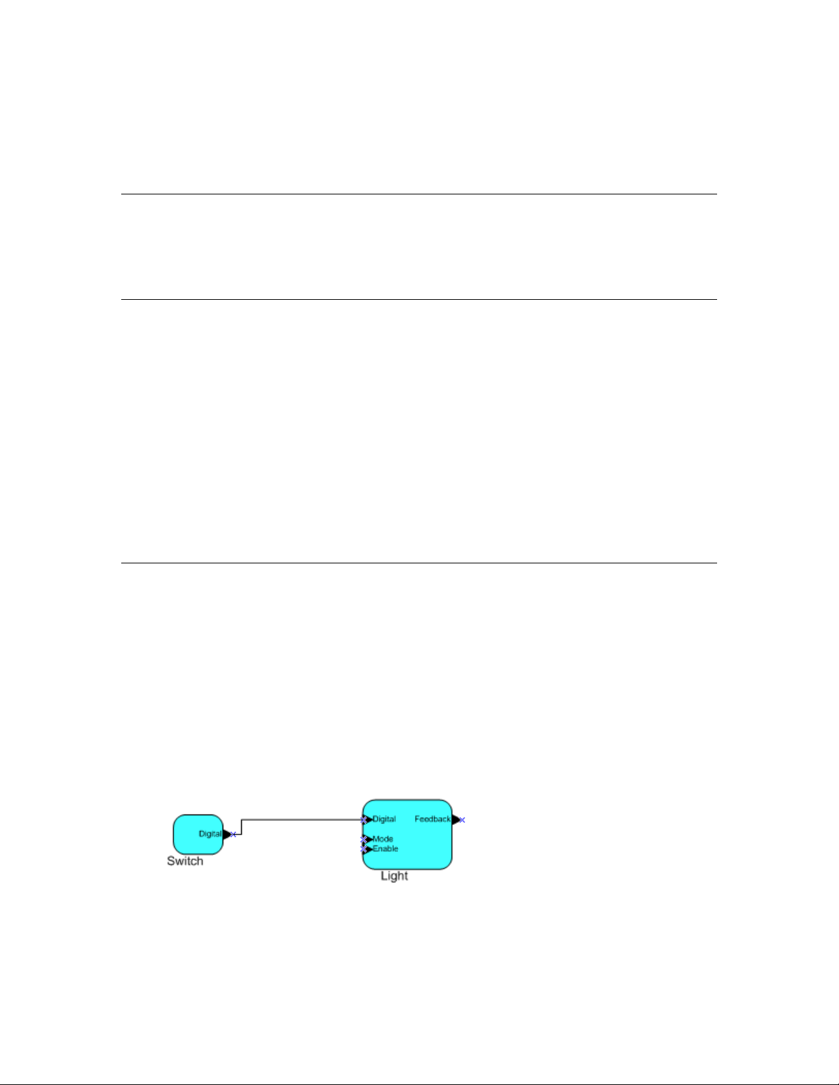
Network variables of identical type and length but opposite directions can be connected to allow the
devices to share information. For example, an application on a lighting device could have an input
network variable based on the SNVT_switch type, while an appl i cati o n on a dimmer-switch device
could have an output network variable of t he same SNVT_switch type. A network management tool
such as OpenLNS CT could be used to connect these two devices, allowing the switch to control the
lighting device, as shown in the following figure:
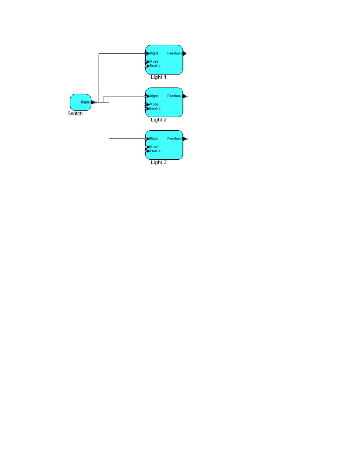
A single network variable may be connected to multiple network variables of the same type but
opposite direction. The following example shows the same switch being used to control three lights:
6 Introduction
Page 23
The application program in a device does not need to know where input network variable values come
from or where output network variable values go. When the application program has a changed value
for an output network variable, it simply assigns the new value to the output network variable.
Through a process called binding that takes place during network design and installation, the device is
configured to know the logical address of the other device or group of devices in the network
expecting that network variable’s values. The device’s embedded firmware assembles and sends the
appropriate packet(s) to these destinations. Similarly, when the device receives an updated value for
an input network variable required by its application program, its firmware passes the data to the
application program. The binding process thus creates logical connections between an output network
variable in one device and an input network variable in another device or group of devices.
Connections may be thought of as virtual wires. For example, the dimmer-switch device in the
dimmer-switch-light example could be replaced with an occupancy sensor, without making any
changes to the lighting device.
Configuration Properties
Configuration properties define how an application device behaves by determining the manner in
which data is manipulated and when it is transmitted. Configuration properties determine the functions
to be performed on the values stored in the network variables. For example, a configuration property
may specify a minimum change that must occur on a physical input to a device before the
corresponding output network vari abl e is u pd a te d. Like network variables, configuration propertie s
have types that determine the type and format of the data they contain.
Functional Blocks
Applications in devices are divided into one or more f unct ional blocks. A functional block is a
collection of network variables and configuration properties that work together to perform a single
task. These network variables and configuration properties are called the functional block members.
For example, a digital input device could have four digital input functional blocks that contain the
configuration properties and output netwo r k vari able members for each of the four hardware digital
inputs on the device. A functional block is an implementation of a functional profile.
Functional Profiles
A functional profile defines mandatory and optional network variable and configuration property
members for a type of functional block. For example, the standard functional profile for a light
OpenLNS CT User’s Guide 7
Page 24
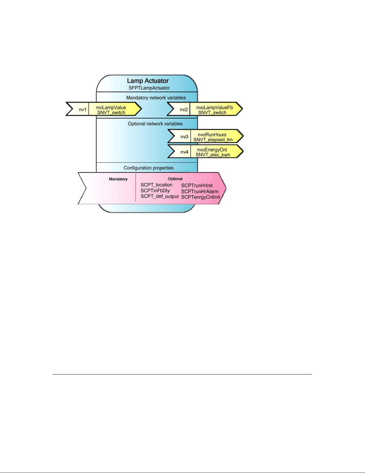
actuator has mandatory SNVT_switch input and output network variables, optional
SNVT_elapsed_tm and SNVT_elec_kwh output network variables, and a number of optional
configuration properties. The following diagram illustrates the components of the standard light
actuator functional profile:
When a functional block is created from a functional profile, the application designer can determine
which of the optional configuration properties and network variables to implement.
Standard Network Variable and Configuration Property Types
Every network variable and configuration property has a type, which determines the content and
structure of the data. To enable devices from different manufacturers to interoperate, the following
standard types are defined:
• Standard Network Variable Types (SNVTs, pronounced snivits). SNVTs contain many common
operational data types. For example, SNVT_temp_p is a network variable type for network
variables containing temperature as a fixed-point number.
• Standard Configuration Property Types (SCPTs, pronounced skipits). SCPTs contain many
common configuration data types. For example, SCPT_location is a configuration proper ty type for
configuration properties containing the device location as a text string.
types.lonmark.org for a list and description of all SNVTs and SCPTs.
See
User-defined Standard Network Variable and Configuration Property Types
Applications may use manufacturer-defined non-standard types—user network variable types
(UNVTs) and user configuration property types (UCPTs)—which are defined in user resource files.
Device manufacturers may provide additional resource files that define these types. See the
NodeBuilder Resource Editor User’s Guide for additional information on creating or using these files.
Subsystems
Devices, routers, and functional blocks are contained in subsystems. With OpenLNS CT, each
subsystem corresponds to one page within an OpenLNS CT drawing. Subsystems allow you to place
devices, routers, and functional blocks onto separate pages for organizati onal pu rp oses . You m a y also
nest subsystems in other subsystems, allowing you to create a subsystem hierarchy for large networks.
For example, a network may consist of HVAC, lighting, security, and operator subsystems. These may
8 Introduction
Page 25

be further divided into subsystems for each floor, and each floor divided into subsystems for each
room.
Supernodes
Using OpenLNS CT, you can also use subsystems to create supernodes. A supernode is a subsystem
with its own network variable interface. You can use supernodes to organize groups of devices into
logical units and to hide complex subsystem details, exposing only the most important network
variables. This structure reduces errors and decreases the time required for network engineering and
commissioning. A network variable interface for a supernode may contain any network variable on
any device functional block found within the supernode or in any of its nested subsystems.
Visio Basics
OpenLNS CT is built on the Visio drawing tool to provide a robust technical drawing environment for
network design. An OpenLNS CT drawing consists of one or more drawing files, and each drawing
file contains multiple subsystems that are each displayed on individual Visio pages. The Visio
documentation provides detailed descriptions of Visio commands and capabilities.
Two key Visio concepts are shapes and stencils. Shapes are reusable drawing objects. A shape may
represent a simple drawing object such as a line, arc, circle, or square, or it may represent a complex
drawing object with special behavior such as OpenLNS CT SmartShapes
SmartShapes for subsystems, application devices, functional blocks, network variables, message tags,
connections, routers, and channels.
®
. OpenLNS includes
To simplify finding and reusing shapes, Visio defines a special type of drawing called a stencil. A
shape contained on a stencil is called a master shape. When you drag a master shape from a stencil to
one of your drawing pages, Visio automatically makes a copy of the master shap e on your drawing and
leaves the master shape unchanged on the s tencil.
You can create custom master shapes and stencils for any set of OpenLNS CT SmartShapes. For
example, OpenLNS CT includes custom master SmartShapes and a custom stencil for SmartServer
devices and functional blocks. You may wish to create your own custom master SmartShapes and
stencils to speed up network design. See Chapter 12,
Master SmartShapes, for more information.
To simplify access to your most commonly used stencils and drawing options, Visio defines another
type of drawing called a template. Templates are drawings that may be used as the starting point when
you create a new drawing. OpenLNS CT includes a L
when you create an OpenLNS CT drawing. If you wish, you can create your own custom OpenLNS
CT template and select it as the default template in the OpenLNS CT Design Manager. See
Network Options in Chapter 3 for more information on selecting the default drawing template.
Creating and Using Custom Ope nL N S CT
ONWORKS template that is used automatically
New
OpenLNS CT User’s Guide 9
Page 26

10 Introduction
Page 27

2
Installing and Activating
OpenLNS CT
This chapter describes how to order OpenLNS CT, install the various software and
components included in your copy of OpenLNS CT, and how to activate OpenLNS CT.
OpenLNS CT User’s Guide 11
Page 28

Ordering OpenLNS CT
You can order OpenLNS CT directly from Echelon, from an Echelon distributor, or from the Echelon
store at
address when you order OpenLNS CT products. Once you complete your order, Echelon will send
you an e-mail message to the provided e-mail address with the activation key for your OpenLNS CT
products. You can order the following products from the Echelon store:
store.echelon.com. If you order from the Echelon store, make sure you provide a valid e-mail
Echelon
Part No.
38000-400 OpenLNS Commissioning Tool Professional Edition (DVD)
38010-400 OpenLNS Commissioning Tool Professional Edition Without Visio (DVD)
38050-400 OpenLNS Commissioning Tool Professional Edition Activation Key
38060-400 OpenLNS Commissioning Tool Professional Edition Without Visio Acti vation Key
38100-400 OpenLNS Commissioning Tool Standard Edition (DVD)
38150-400 OpenLNS Commissioning Tool Standard Edition Activation Key
38160-400 OpenLNS Com missioning Tool Standard Edition Without Vi si o Act i vat i o n Key
38300-400 OpenLNS Commissioning Tool Trial Edition Without Visio Activation Key
You can download your OpenLNS CT products from the Echelon Web site at
www.echelon.com/openlns, and then install and activate them as described in the next section.
OpenLNS CT Product
Installing and Activating OpenLNS CT
You can install a licensed copy of OpenLNS CT on up to two computers, a primary and a secondary
computer, provided that the following requirements are met: only the OpenLNS CT user on the
primary computer can use the copy of OpenLNS CT on the secondary computer and the OpenLNS CT
software may only be used on one computer at a time. See the
Agreement in Appendix C for more information. To begin your installation, follow these steps:
OpenLNS CT Software License
1. If you are installing a version of OpenLNS CT that does not include Visio, you must separately
purchase and install the 32-bit version of Visio 2010 or Visio 2003 before installing the OpenLNS
CT software.
2. If you do not have an Echelon download account, create one on the Echelon Web site at
www.echelon.com/support/downloads/accounts. Your account will enab le you to download
OpenLNS software from the Echelon Web site; make activating and managing licenses for
multiple Echelon products easier; enable you to return, transfer, and recover licenses; and help you
receive technical support from Echelon faster.
3. Download OpenLNS CT from the Echelon Web site and run the OpenLNSCTSetup.exe file, or
insert the OpenLNS CT DVD into your DVD-ROM drive.
If you are installing OpenLNS CT from a DVD and the OpenLNS CT setup application does not
launch immediately, click Start on the taskbar and then and click Run. Browse to the
OpenLNSCTSetup application on the OpenLNS CT DVD and click Open. The Select
Components dialog box opens.
12 Installing and Activating OpenLNS CT
Page 29
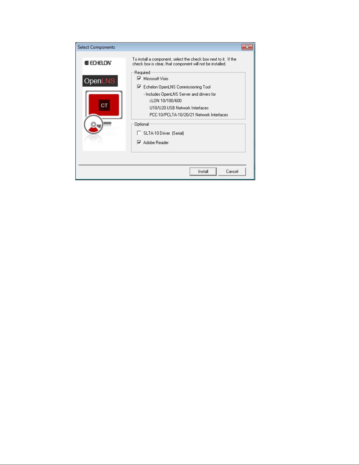
4. Select the components that you wish to install by selecting the appropriate check boxes on the
Select Components dialog box.
• Microsoft Visio: Installs the 32-bit version of the Visio 2010 drawing tool. To install the
32-bit version of Visio 2010, your computer cannot have the 64-bit version of any Office
2010 application installed on it.
OpenLNS CT is not compatible with the 64-bit version of Visio 2010 (even if your computer
is using a 64-bit operating system), and it is not compatible with any version of Visio prior to
Visio 2003. If you already have a 64-bit version of any Office 2010 application, you must
uninstall it before installing the 32-bit version of Visio. You can reinstall the 32-bit version of
any 64-bit Office software that you have installed.
• Echelon OpenLNS Commissioning Tool: Installs the required components of OpenLNS
CT. Installing OpenLNS CT automatically installs OpenLNS Server, the OpenLNS CT XML
, and the drivers for the following OpenLDV 4.0-compatible network interfaces:
Utility
o Remote Network Interfaces (RN Is): SmartServer , i.LON 100 Internet Server, i.LON 600
IP-852 Router, and i.LON 10 Ethernet Adapter
o Local USB network interfaces: U10/U20 USB network interfaces.
o Local PC card network interfaces: PCC-10 and PCLTA-10, 20, and 21 PCI network
interfaces. The PCC/PCLTA and SLTA-10 network drivers are compatible with 32-bit
versions of Windows only and are not instal le d on 6 4-bi t versi o ns of Wi n do ws.
If you are using OpenLNS CT on an IP-852 channel, you will need an IP network interface
card (such as Ethernet or WiFi) or modem with PPP software. An IP network interface is also
required if you are using an IP-852 interface such as a SmartServer (with IP-852 routing
option), i.LON 100 Internet Server (with IP-852 routing option), or i.LON 600 IP-852 Router.
If you are using another OpenLNS interface, install the network interface hardware and driver
following the instructions provided with the hardware.
Most network interfaces include an application that handles network interface configuration.
You must perform this configuration before you can use OpenLNS CT while attached to a
network. The application may handle host details such as IRQ assignment, and it may also
manage network parameters such as buffer counts and transceiver types.
OpenLNS CT User’s Guide 13
Page 30
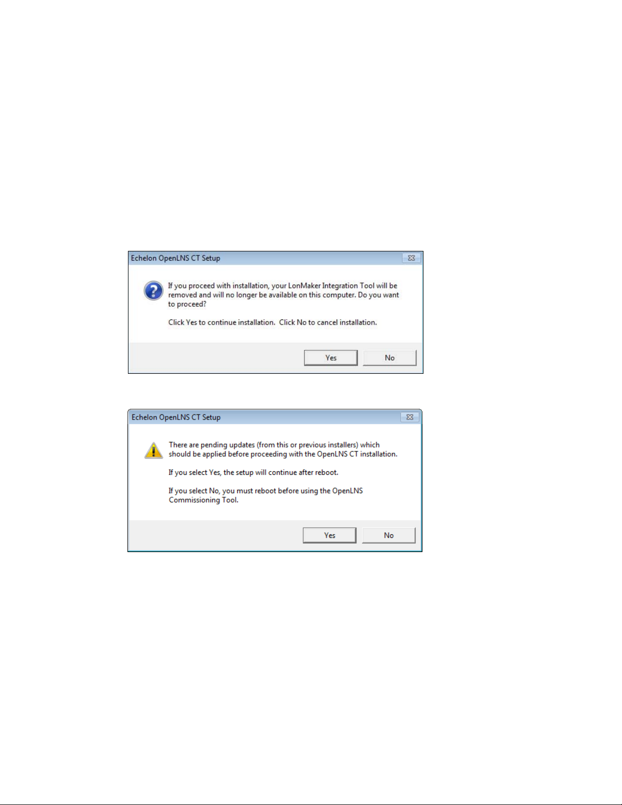
You can use the L
ONWORKS Interfaces application in the Control Panel to define, configure,
and test RNIs, IP-852 network interfaces, USB 10/20 network interfaces, and PCC/PCLTA
network interfaces.
• SLTA-10 Driver (Serial): Installs the network driver for the SLTA-10 serial network
interface. Click this check box if you are using an SLTA-10 serial adapter as your network
interface. This option is not available on 64-bit versions of Windows.
• Adobe Reader: Installs Adobe Reader 9.2, which is a free program that allows you to read
Adobe Acrobat portable document files (.pdf extension). Many of the L
ONMARK reference
documents are exclusively in PDF format. You can clear this check box if you already have a
PDF reader application.
5. Click Install. If you are upgrading from the LonMaker Integration Tool, a message opens
informing you that installing OpenLNS CT will remove any version of the LonMaker tool on your
computer.
6. Click Yes to continue installing OpenLNS CT. The installation program installs the selected
components sequentially, prompting you for required reboots.
7. During the installation, the following dialog opens, displaying the current progress of the
OpenLNS CT setup:
14 Installing and Activating OpenLNS CT
Page 31

If you selected the Visio component in the Select Components window, the Microsoft Visio setup
wizard opens. Follow the instructions in the installation program to complete the Visio setup.
8. Install OpenLNS CT following these steps:
a. The OpenLNS CT setup program begins automatically with the Welcome window opening.
b. Click Next. The License Agreement window opens.
OpenLNS CT User’s Guide 15
Page 32

c. Read the license agreement and click Yes if you agree with the terms. The Customer
Information window opens.
d. Enter your name, organization, and the OpenLNS CT activation key in the appropriate fields.
The name and organization may be entered automatically based on the user currently logged
on and whether other Echelon products are installed on your computer.
If you renewed your annual maintenance and you are installing your upgrade on the same
computer as your original OpenLNS CT software, your activation key is automatically
displayed. If you are installing an upgrade on a different computer, you must find the
activation key that you saved from your orig i nal versi o n of OpenLNS CT.
Under Echelon Account, enter the user name (e-mail address) and password you created for
your Echelon download account (see step 2 if you do not have an Echelon download account).
Click Next.
16 Installing and Activating OpenLNS CT
Page 33

e. If your computer is connected to the Internet, the OpenLNS CT installer connects to the
Echelon License Server, the License Server issues activation licenses for OpenLNS Server
and OpenLNS CT, and the installer stores the licenses on your computer.
If your computer is not attached to the Internet, you can use the Echelon License Wizard to
manually activate OpenLNS CT via e-mail or phone after installing the software (e-mail is
recommended). See the next section,
Manually Activating OpenLNS CT, for more
information.
f. If the Destination Location window opens, choose a L
ONWORKS folder in which you want the
OpenLNS CT software installed, and then click Next. The OpenLNS CT software will be
installed in an OpenLNS CT folder below the L
previously installed other Echelon software on this computer, use the same L
ONWORKS folder that you specify. If you
ONWORKS
folder.
The default L
ONWORKS folder is C:\Program Files\LonWorks (on a 32-bit version of
Windows) or C:\Program Files (x86)\LonWorks (on a 64-bit version of Windows). If you
previously installed other Echelon software on this computer, the last L
ONWORKS folder that
you selected will be displayed as the default, and you cannot change this value.
g. The Ready to Install window opens. Click Install to begin the OpenLNS CT installation.
h. If you need to reboot your computer, a window will appear prompting you to select to reboot
your computer now or later. After OpenLNS CT installation and any required reboots have
been completed, a window will appear, stating that OpenLNS CT has been installed
successfully and providing you with the option to view the ReadMe file. The ReadMe file
contains information that is not included in this user’s guide.
OpenLNS CT User’s Guide 17
Page 34

i. Click Finish. The ReadMe file opens if the Show the Readme File check box was selected.
When you finish reading the ReadMe file, close the window.
j. A confirmation dialog opens stating that the selected components have been installed. Click
OK.
Note: Do not uninstall any of the following applications and components that are used by
OpenLNS CT: OpenLNS Server, OpenLNS XML Utility, OpenLDV, Visio, LonMark Resource
Files, Multi-Port Router 50, and the IP-852 Configuration Server. Uninstalling any of these
applications and components will cause OpenLNS CT to stop running.
9. If your computer was not attached to the Internet when you were installing OpenLNS CT, proceed
to the next section to manually activate your software. OpenLNS CT will not run until it is
activated.
18 Installing and Activating OpenLNS CT
Page 35

Manually Activating OpenLNS CT
If your computer was not attached to the Internet when you installed OpenLNS CT, you can use
the Echelon License Wizard to activate OpenLNS Server and OpenLNS CT after you complete the
software installation. You can activate your software via the Internet if your computer is now
online, or you can activate your software via e-mail or phone if your computer is still offline. To
use the License Wizard to activate your OpenLNS CT software, follow these steps:
1. Open the Echelon License Wizard. Click Start, click Programs, point to Echelon License
Wizard, and then click License Wizard. The Echelon License Wizard opens. Click Next.
2. The Step 1: What would you like to do? dialog opens.
OpenLNS CT User’s Guide 19
Page 36
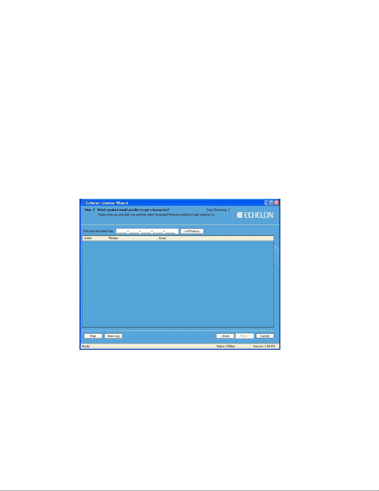
3. To activate your OpenLNS CT software using the over the Internet or via e-mail, click Activate
Product Licenses and then click Next.
To activate over the phone, click Show Advanced Tasks, Upgrade a Product License over the
Phone, and then follow the instructions in the License Wizard. If your computer is offline,
activate via e-mail if you have e-mail access because activating over the phone requires manually
entering many lengthy alpha-numeric strings.
4. If your computer is online, the Step 2: What is Your Account Information dialog opens.
Complete the following steps to activate your software (if your computer is still offline, proceed to
step 5):
a. Enter your account information and/or your OpenLNS CT activation key, and then click Next.
b. The Step 3: Which License Would You Like to Activate? dialog opens.
c. Select Activate from the Action list for both OpenLNS Server and OpenLNS CT, and then
click Next.
d. The Step 4: Status dialog opens, and the License Wizard activates your licenses.
e. Click Exit to close the License Wizard.
5. If your computer is still offline, the Step 2: Which Product Would You Like to Get a License
For dialog opens.
6. Enter your OpenLNS CT activation key in the Enter Your Activation Key box and then click
List Products. The License Wizard lists your OpenLNS Server and OpenLNS CT products.
Select Activate from the Action list for both OpenLNS Server and OpenLNS CT, and then click
Next.
20 Installing and Activating OpenLNS CT
Page 37
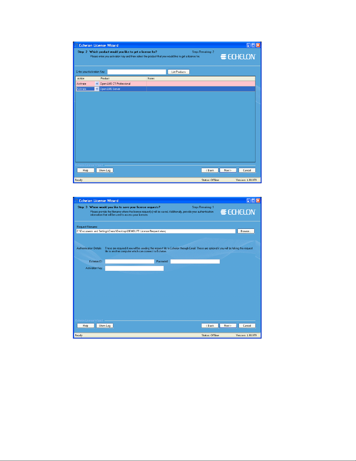
7. The Step 3: Where Would You Like to Save Your License Requests? dialog o pen s.
8. In the Request File Name property, enter a full path where a license request file (.elwrq
extension) is to be saved, or click Browse, specify the directory where the license request file is to
be saved, and then enter a name for the file.
Under Authentication Details, enter the Echelon ID (e-mail address) and Password you created
for your Echelon download account (see step 2 if you do not have an Echelon download account).
The Activation Key box displays the 25-character alphanumeric string for the Echelon product to
be activated. Do not modify this property.
Click Next.
9. The Status dialog opens. The License Wizard confirms the creation of the license request file.
OpenLNS CT User’s Guide 21
Page 38
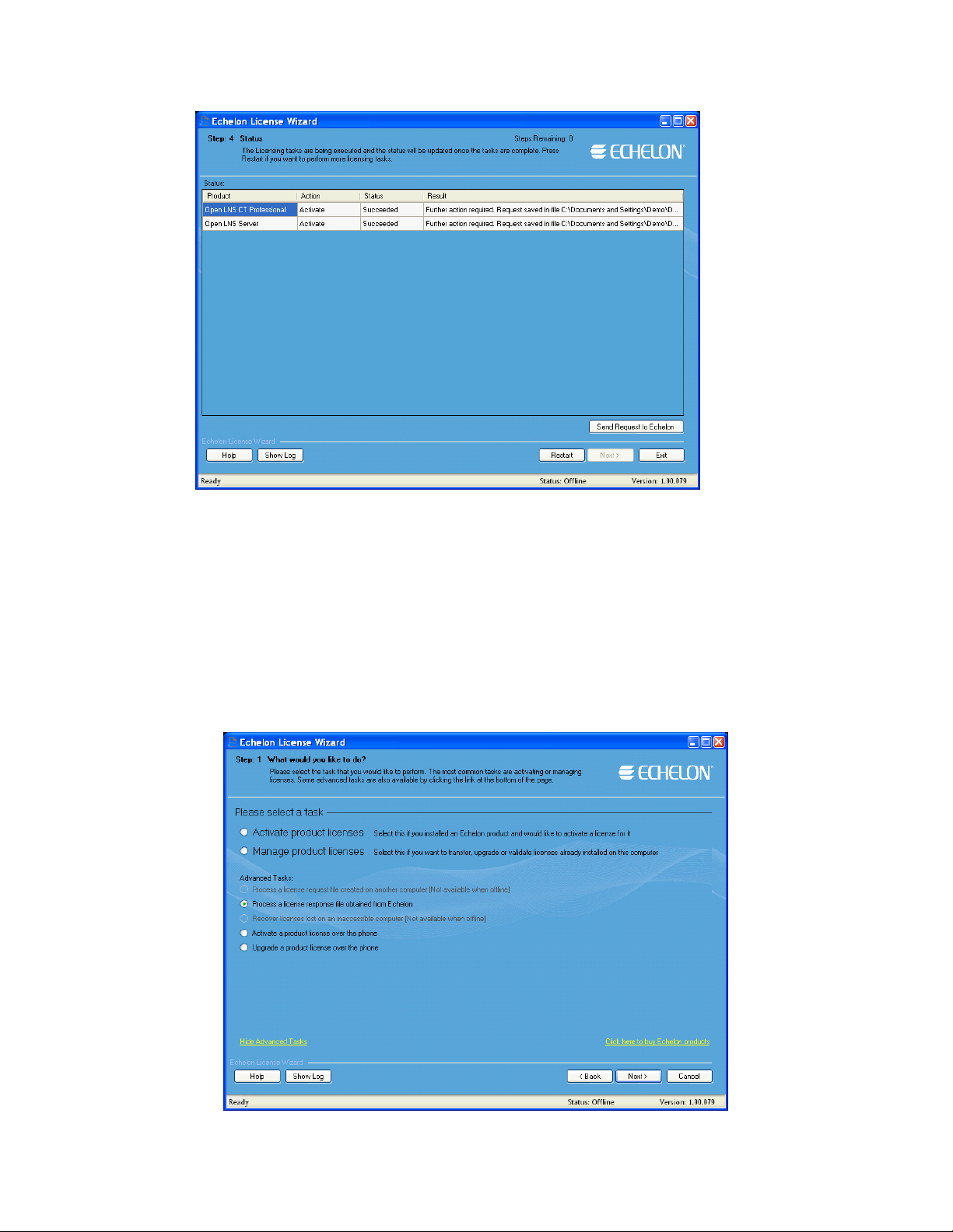
10. Click Send Request to Echelon to e-mail the license request file to Echelon at
activation@echelon.com. Echelon will send you an e-mail message with a license response
(.elwrs extension) file. For faster activation, copy the license request file to an Internet-connected
computer with the License Wizard installed on it and importing it into the License Wizard. The
License Wizard creates the license response file, which you can then copy to the original
computer.
11. Import the license response (.elwrs ex tension) file into the License Wizard and activate your
OpenLNS Server and OpenLNS CT licenses following these steps:
a. Start the Echelon License Wizard.
b. In the Task Selection dialog, click the Show Advanced Topics link, and then click the
Process a License Response File Obtained from Echelon option.
22 Installing and Activating OpenLNS CT
Page 39

c. The Import License Request or Response File dialog opens. In the File Name property,
enter the full path of the license response file (.elwrs extension), or click Browse and then
select the file. Click Next.
d. The Check License Response File dialog opens. Confirm that the Echelon product licenses
in the license response file are the ones you want to activate. Click Next. The License Server
installs and activates the licenses in the license response file.
e. The Status dialog opens and confirms that the OpenLNS Server and OpenLNS CT licenses
have been successfully activated.
OpenLNS CT User’s Guide 23
Page 40
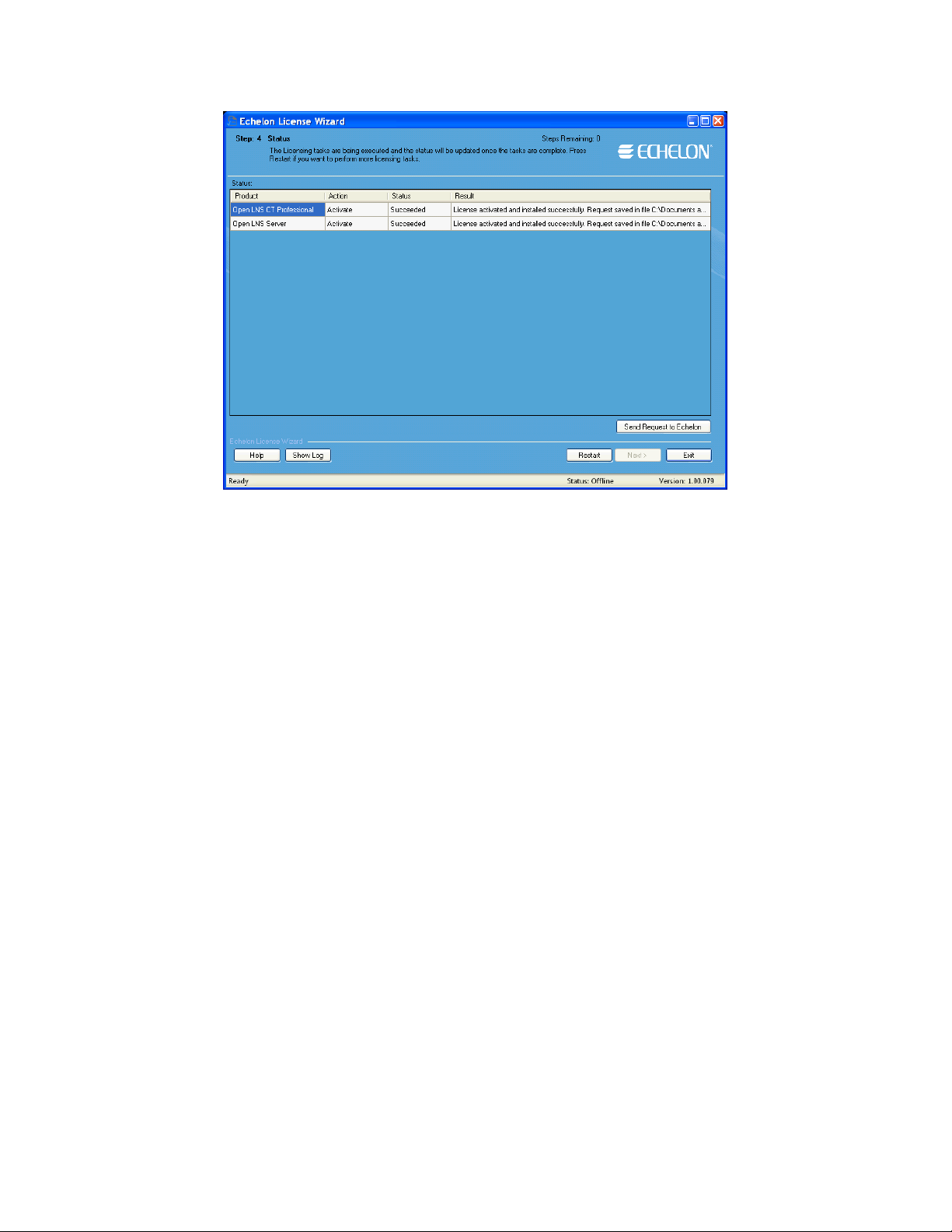
12. Click Exit to close the License Wizard.
24 Installing and Activating OpenLNS CT
Page 41

Getting Started
This chapter describes how to plan and create OpenLNS CT network designs. It
describes how to use the OpenLNS CT Design Manager to create, open, and manage
OpenLNS CT network designs, and it explains how to set up a network interface that
enables OpenLNS CT to communicate with the network. It summarizes the different
OpenLNS CT client types, and it explains how to use OpenLNS CT remotely, and
how to create and use user profiles.
3
OpenLNS CT User’s Guide 25
Page 42

Design Overview
To prepare to design an OpenLNS CT network, follow these steps:
Define network requirements and organizat i on.
1.
Select a network installation scenario.
2.
Determine user permissions for viewing and changing the network.
3.
Optimize network performance.
4.
Defining Network Requirements and Organization
You can define your network’s requirements by evaluating which devices (sensors, actuators, and
controllers) are needed to achieve the desired network functions and how the devices will be integrated
into the network. For example, your network may need a simple fan coil unit, which could require a
fan start/stop relay, a cooling coil valve, and a supply air temperature sensor. You could use digital
output, analog output, and analog input devices, respectively, to integrate these devices (the analog
output module could also includes a PID controller you can use to control the fan coil unit).
Once you define the network requirements, you can figure out how to organize the network in
OpenLNS CT. You can help organize the network by answering the following questions:
• How will devices and functional blocks be grouped within subsystems?
• Which functional blocks are needed for the devices to accomplish desired tasks?
• How do functional blocks need to be configured and connected to correctly interpret values from
sensors, perform any necessary calculations, and drive actuators?
Selecting a Network Installation Scenario
You can design your entire network without commissioning any devices until after you r design is
complete, or you can design your network and commission devices at the same time. These two
approaches are called installation scenarios. The first network installation scenario is called the
engineered system and the second is the ad-hoc system. You can use both scenarios withi n a single
system, or you can use either exclusively. The best scenario for a given network depends on many
factors including the skill level of the installer, desired flexibility for the network, and the end-user
requirements.
Engineered System Scenario
The engineered system scenario allows you to design the network without having access to the
physical devices
First, you design the network offsite using OpenLNS CT. You drag OpenLNS CT SmartShapes
representing devices, routers, IP-852 routers, functional blocks, and connections from an OpenLNS
CT stencil to an OpenLNS CT drawing and arrange them on the drawing, and into multiple subsystems
if desired.
Once you are onsite and have attached an OpenLNS CT computer to the network, you then
commission the physical devices. OpenLNS CT commissions a device by configuring the physical
device to match the configuration that you specified in the OpenLNS CT drawing.
Engineered systems must often be modified du ri n g o n-sit e i nstal l a ti on due to differences between
as-drawn plans and the physical network. OpenLNS CT supports on-site changes to the engineered
system to allow for these changes during commissionin g.
The advantage of the engineered system scenario is that it makes network installation quick, easy, and
error-free because most of the time-consuming data entry and processing is done offsite during the
design phase. This scenario is often used for building and industrial automation systems, in which the
original design closely matches the actual installation.
26 Getting Started
Page 43

Ad-Hoc System Scenario
The ad-hoc system scenario allows you to design and install the network onsite. In this scenario,
OpenLNS CT loads the network configuration information into each device as you define devices,
configurations, and connections. This is different from the engineered system scenario in that
information is incrementally loaded to the physical devices.
The advantage of the ad-hoc system scenario is its flexibility, as the installer can make decisions
onsite. It is most appropriate for simpler systems in which the details of the system to be installed are
not known prior to commissioning.
The disadvantages of the ad-hoc system scenario are that it’s slower for large systems and requires the
same person to do both the network design and installation.
Determining User Permissions
When you create an OpenLNS CT network design, OpenLNS CT does not assign any security to the
network drawing. It defaults to one user—the administrator of the OpenLNS CT drawing. While this
default is permissible if one person is performing the network installation in a secure environment, it
may not be suitable for multi-user or insecure environments. In these environments, you need to create
and manage user profiles to control access to your OpenLNS CT network design. This will prevent
any unauthorized changes to your OpenLNS CT network design and enable you to better manage the
installation or repair of a system.
User profiles allow you to create access controls for a network drawing and its subsystems and set
privileges for actions that can be performed on OpenLNS CT objects. For example, you could have a
scenario in which a system integrator has access to the entire network and can add or change
application devices and routers, while the installers can also access the entire network, but only can
commission the application devices and routers.
You might use a different scenario if you are working with multiple system integrators who are all
supplying devices for your network. In this case, you can give each integrator access to their
subsystem only but allow them to freely change the subsystem drawing and commission devices. This
prevents one integrator from accidentally modifying a drawing created by another integrator.
By default, user profiles are not enabled for new networks. To enable user profiles, you must first
assign an Administrator password and create new user profiles as described in
Administrator can create, modify, and delete user profiles.
Once you logon as a user other than the Administrator, you can still create new user profiles, as
described in Creating a New User Profile, and you can change your password as described in
Changing Passwords.
For information on using user profiles with OpenLNS CT remotely, see
User Profiles.
with
User Profiles. The
Using OpenLNS CT Remotely
Optimizing OpenLNS CT Network Performance
Many factors affect the performance of an OpenLNS CT network design. The following are guidelines
for several aspects of your OpenLNS CT network design that can help optimize network
performance— especially for large networks.
Drawing Files
A single drawing file should not be larger than 3MB, or consist of more than 20 typical pages or 10
complex pages. If you are creating a network exceeding these guidelines, design the subsystems in
multiple drawing files. For optimum performance, devices and their associated functional blocks
should be contained within the same drawing file, as should all members of the same connection.
OpenLNS CT User’s Guide 27
Page 44

When designing multiple drawing files, organize the individual drawing files as subsystems within the
top-level drawing file, and limit the top-level drawing to contain only those subsystems. This
minimizes the number of drawing files that must be opened as you descend the subsystem hierarchy.
Avoid deep subsystem hierarchies with long subsystem names that results in long subsystem paths.
Subsystem paths may be stored in devices to help the network recovery process if you lose the network
database, but devices have limited memory available to store the network path. Furthermore,
visualization tools such as Wonderware’s InTouch
exceeded with long subsystem paths.
®
have limits to item name lengths that can be
Network Changes
To improve network performance when making numerous network changes at one time, set OpenLNS
CT to OffNet. This will allow you to make the changes quickly, as the changes will be saved in the
OpenLNS network database instead of being sent to the physical devices. When you finish making the
changes, set OpenLNS CT to OnNet and the changes are propagated to the physical devices.
Connections
If you will be making changes to a subsystem, limit the number of connections monitored by
OpenLNS CT to less than five per subsystem. Having more than five monitored connections in a
subsystem will increase the time required to perform certain network management operations.
Alternatively, you can turn off all monitoring while making changes by right-clicking a clear space in
the subsystem page and clicking Enable Monitoring if it is currently set. You can turn monitoring on
again after making the changes.
If you are using an OpenLNS application that does not support monitor sets (groups of data points that
OpenLNS CT uses to monitor and control network variables) and you are making many bound
connections to the OpenLNS application, make the bound connections persistent. This will improve
network performance. Conversely, non-persistent bound connections, which can be created in an
OpenLNS CT network with OpenLNS applications other than OpenLNS CT, can significantly increase
the time required to open and close an OpenLNS CT drawing. OpenLNS tools that suppor t mon itor
sets, such as OpenLNS CT, enable monitoring of monitor points to be setup quickly once an OpenLNS
CT network is opened. This is because points in monitor sets are always persistent. OpenLNS CT
automatically creates monitor sets for connection monitoring when monitoring is enabled on an
OpenLNS CT network. To enable monitoring, right-click a clear space in the subsystem page and
clicking Enable Monitoring if it is not currently set. For more information on monitor sets, see the
OpenLNS Programmer’s Guide.
Sharing the OpenLNS Interface with the LNS DDE Server
If the LNS DDE Server and OpenLNS CT are running con currently and sharing the same OpenLNS
network interface, limit the polling rate of the LNS DDE server to 10 polls per second on a
ONWORKS channel. Having the LNS DDE Server polling abov e this rate will degrade network
L
performance. By default, the LNS DDE server polls active network variables every 1 second, so more
than 10 active network variables running at the default poll interval can impact network performance.
You will see similar performance degradation if you have any other OpenLNS monitoring application
sharing the OpenLNS network interface with OpenLNS CT, or if you are using connection monitoring
in OpenLNS CT.
If you will be making numerous network changes, either disable the LNS DDE Server and any other
OpenLNS monitoring applications, or reduce the polling rate to a maximum of 10 polls per second
while you are making changes.
Functional Blocks
If you have a large network with many unconnected network variables on the functional blocks, delete
the unused network variable SmartShapes. Network variable SmartShapes add performance overhead,
yet they are not required if they are not connected. You can re-add network variable SmartShapes to a
28 Getting Started
Page 45

functional block if you need to connect them later. To simplify following this guideline, you can
create functional block master SmartShapes with your most commonly used network variables. See
Creating a Functional Block Master SmartShape in Chapter 4, Designing Networks for more
information.
Subsystems
Subsystems allow you to divide a large network into more manageable parts. For example, in a
building control network, one subsystem could contain lighting controls and another temperature
controls. Each subsystem is represented by a page of an OpenLNS CT drawing and by a subsystem
SmartShape on the drawing page of its parent subsystem. You can nest subsystems like directories on
your computer, so the temperature control subsystem could contain other subsystems representing, for
example, each floor of the building. You can also create subsystems in separate OpenLNS CT
drawings. Using this feature, you can create large networks while maximizing Visio’s performance by
limiting the number of pages in a single drawing. You can also create a separate OpenLNS CT
drawing for each user for large networks with multiple installers.
If you are creating a network that needs more subsystems than 20 typical pages or 10 complex pages,
you should divide it into two or more drawing files. For optimum performance, devices and their
associated functional blocks should be contained within the same drawing file, as should all members
of the same connection.
A supernode is a special type of subsystem SmartShape that has one or more network variable
interfaces on it. Any network variable or message tag on any functional block in the subsystem may
be exported to the subsystem SmartShape. This doe s not c reat e new net w or k vari ables or message
tags, but exports the network variable or message tag’s connection point one or more levels up the
subsystem hierarchy. Using a supernode allows you to provide a simple interface to an arbitrarily
complex subsystem. For example, a supernode that contains lighting controls may have a network
variable interface that allows the devices contained within it to be put into emergency override. This
allows the integrator to easily identify the critical interfaces into the subsystem, while ignoring those
that are typically only used internally by the subsystem.
OpenLNS CT Design Manager Overview
The OpenLNS CT Design Manager is an essential tool for managing your OpenLNS CT networks.
With the OpenLNS CT Design Manager, you can create, open, and delete networks; back up and
restore networks to prevent against loss; and configure default settings for new networks to speed up
the network creation process.
To open the OpenLNS CT Design Manager, click Start on the taskbar, point to Programs, point to the
Echelon OpenLNS CT folder, and then click OpenLNS CT. The O penLNS CT Design Manager
opens.
OpenLNS CT User’s Guide 29
Page 46

The OpenLNS CT Design Manager consists of five tabs that let you perform the following functions:
• General. Create, open, copy, delete, and backup/restore OpenLNS CT network designs; start the
OpenLNS Server application; and import and defragment OpenLNS network databases.
• Options. Set a prioritized list of languages for L
• New Network Options. Configure default properties for the pages in the Network Wizard and
options to skip the pages, and set the network components.
• OpenLNS CT Stencils. Add, remove, or modify the properties of OpenLNS CT stencils.
• OpenLNS CT Default Options. Configure the default properties and behavior for OpenLNS CT
objects (for example, adding devices, adding functional blocks, and backing up and synchronizing
the OpenLNS database).
ONMARK resource files.
General
You can use the General tab in the OpenLNS CT Design Manager to create, open, copy, delete,
backup, restore OpenLNS CT network designs; start the OpenLNS Server application so remote clients
can access the OpenLNS network database; import a database and then create a new OpenLNS CT
drawing from it; and defragment OpenLNS network databases. To use the General tab, enter the
following data in the boxes and click the following buttons:
New Network
Network Name Specifies the name of the new OpenLNS CT network design to be
created. The name must be unique to all the OpenLNS CT networks
on this computer. You can enter up to 16 characters and include
embedded spaces. The name is not case sensitive; therefore, you
30 Getting Started
Page 47

cannot create two networks with names that differ only in
capitalization.
The initial default network name is “Network 1”. OpenLNS CT
automatically increments the index in the default network name so
that the network names are unique for subsequent netwo rks y ou
create using the default name. After you create a network with a
different name than the initial default, the default network name will
become the last network created with an incremented index. For
example, if you create a new network named “Test”, the default
network name will be “Test 1”. If you create the “Test 1” network,
the default network name will become “Test 2”, and so on.
Create Network Creates and opens a new OpenLNS CT network design consisting of
a new OpenLNS network database and a new OpenLNS CT
drawing.
Show all options Displays all the pages in the Network Wizard as the network is
opened, regardless if the Skip this Prompt option is selected for a
page in the New Network Options tab.
To create networks with one-click, clear this check box and select
the options in the New Network Options tab to skip the pages in the
Network Wizard.
Existing Network
Drawing Directory Selects a file from the folder indicated in the Drawing Base Path
list. To open an existing OpenLNS CT network design, select the
folder containing the OpenLNS CT drawing file.
Drawing Name Selects an OpenLNS CT drawing from all the OpenLNS CT
drawings contained in the selected drawing folder. Select the
OpenLNS CT drawing you want to open, delete, or backup.
Database Name Selects an OpenLNS network database from all the OpenLNS
network databases on this computer. Select the database you want to
defragment, delete, or backup, or from which you want to start the
OpenLNS Server. This field is not used for the Open Network,
Open Copy, and Restore operations.
Open Network Opens the OpenLNS CT drawing and associated OpenLNS network
database specified in the Drawing Name list. The Database Name
list is ignored by this operation.
Open Copy Opens a copy of the OpenLNS CT drawing specified in the Drawing
Name list, making a copy of the OpenLNS CT drawings and the
associated OpenLNS network database. This copy is created like a
new network. (You will be prompted to choose a new top-level
drawing name and database path. The Database Name list is
ignored by this operation.)
Delete Deletes the OpenLNS CT drawing and OpenLNS network database
specified in the Drawing Name and Database Name lists,
respectively. To delete only a drawing or a database, select <none>
in the appropriate list.
Defragment Database Defragments and recreates the index for the OpenLNS CT database
specified in the Database Name list. This can reduce the size of and
decrease the access time to a network database that has grown in size
because of many changes. Backup the database before
defragmenting it in the event an error occurs during the
OpenLNS CT User’s Guide 31
Page 48

defragmentation process.
Start OpenLNS Server Starts the OpenLNS Server application so that remote client
computers can access the OpenLNS network database.
Backup Opens the OpenLNS CT Backup dialog, in which you can back up
the network database specified in the Database Name lists and all of
associated drawing files.
Manually Backing Up an OpenLNS CT Network in Chapter 7,
See
Maintaining Networks, for more information on how to use the
OpenLNS CT Backup dialog. See
Backup/Restore Options in
Appendix A for the default backup options you can set.
Show all options If this check box is selected, all of the network option windows will
be presented as the network is opened regardless if the Skip this
Prompt option had been previously selected.
Restore Restores an OpenLNS CT drawing and OpenLNS network database
from an OpenLNS CT backup file. See
4Restoring an OpenLNS CT
Network in Chapter 7, Maintaining Networks, for more information.
Backup/Restore Options in Appendix A for the default restore
See
options you can set.
Import Imports an OpenLNS network database (objects.dat file) into
OpenLNS so that it opens in the Database Name box. The imported
database may have an OpenLNS CT drawing associated with it.
Select the folder containing the OpenLNS network database you
want to import. If the database does not have an OpenLNS CT
drawing associated with it, you can then click Create Drawing to
create an OpenLNS CT drawing based on the imported database.
Settings
Drawing Base Path Determines the directory that will be used by the Drawing
Directory list. All of the folders in this directory will be listed in the
Drawing Directory list. You can browse through the folders to find
the desired path or enter the pathname.
Add Lets you select a drawing folder to add to the Drawing Base Path
list.
Exit Closes the OpenLNS CT Design Manager. This does not close Visio
or any open networks.
To automatically exit the Design Manager after opening an
OpenLNS CT drawing, click the Options tab in the OpenLNS CT
Design Manager and select the Exit Design Manager After
Launching Visio check box.
Options
The OpenLNS CT Design Manager’s Options tab allows you to set a prioritized list of languages for
ONMARK resource files. This list is then applied to all new networks you create.
L
When OpenLNS CT displays documentat i on for sel ect ed devices, functional blocks, and network
variables, it uses the definitions contained in L
ONMARK resource files. You can display the LONMARK
resource file information in different languages by specifying a prioritized list of languages for
ONMARK resource files in OpenLNS CT.
L
32 Getting Started
Page 49
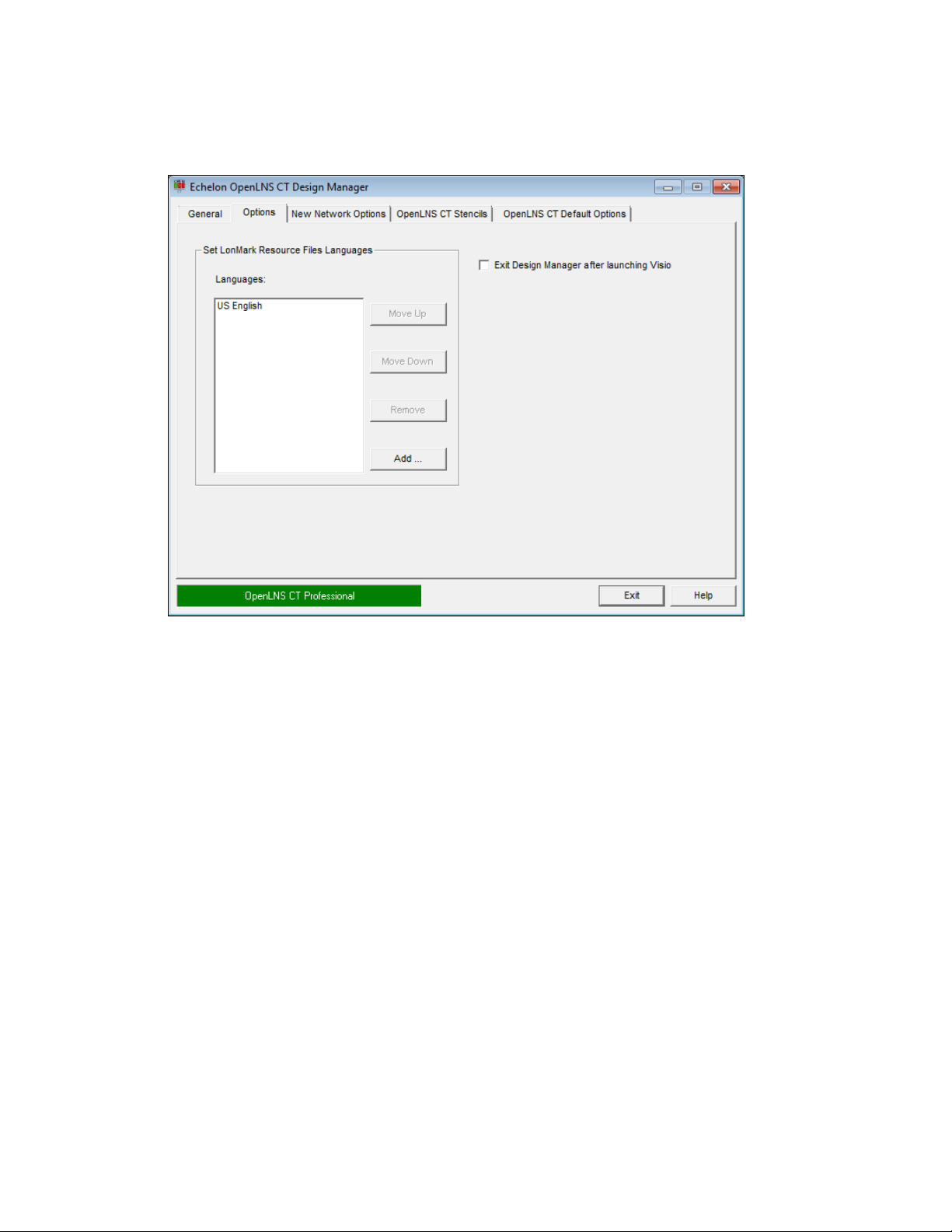
You can set the resource file language for a specific network while in OpenLNS CT by clicking
Add-ins, clicking OpenLNS CT, clicking LonWorks Network, clicking Network Properties, and
then clicking the Resource File Language tab.
The OpenLNS CT Design Manager’s Options tab contains the following options:
Set L
ONMARK
Resource Files
Languages
Allows available language-specific L
added, removed, or reordered in the languages list. When searching
for a resource definition such as an NV field name, OpenLNS CT
ONMARK resource files to be
searches the first language file in the list for the device information,
then the second language file in the list, and so on until it finds the
information for the specified device. If no match is found and the
device information is found in the corresponding U.S. English file,
the English text will be used to display the information.
U.S. English is the default language and cannot be removed from the
list. The language-specific L
ONMARK resource files added to the list
must be installed and available to OpenLNS CT. Usually they will
have been installed if available and you click Add to add them to the
list.
Languages Lists the languages in the order they will be searched for device
information.
Move Up Moves the selected language up one position in the list.
Move Down Moves the selected language down one position in the list.
Remove Removes the selected language from the list.
Add Adds a language to the end of the list.
Exit Design Manager
after Launching Visio
Selecting this option automatically closes the OpenLNS CT Design
Manager after launching Visio.
OpenLNS CT User’s Guide 33
Page 50

New Network Options
You can use the New Network Options tab to set the default network interface, automatically register
plug-ins, set the default network management mode, and set the default drawing template. The
properties you set are then applied to each new network you create.
You can also select options to have OpenLNS CT skip the pages in the Network Wizard when opening
a network. If you additionally clear the Show all Options check box under the New Network box in
the General tab, you can create new networks with one-click, skipping all the pages in the Network
Wizard.
The OpenLNS CT Design Manager’s New Network Options tab contains the following options:
Network Interface
Network Attached Select this check box to specify that the OpenLNS CT computer will
Network Interface
Name
Skip Network Interface
Options Page
Plug-Ins
Register Plug-Ins Select this check box to register all enabled plug-ins when you create
34 Getting Started
be attached to the physical network so that OpenLNS CT can
communicate with the physical devices.
Clear this check box if you the OpenLNS CT computer will not be
attached to the network. This check box is cleared by default.
Select the OpenLNS network interface to be used for communication
between the OpenLNS CT computer and the physical network. This
option is only available if you selected the Network Attached check
box.
Skips the network interface page in the Network Wizard when you
create a new OpenLNS CT network.
a new OpenLNS CT network.
Page 51

Skip Plug-ins Options
Page
User Logon
Skip Logon Options
Page
Management Mode
Skips the plug-in registration page in the Network Wizard when you
create a new OpenLNS CT network.
Skips the user logon page in the Network Wizard when you open an
OpenLNS CT network.
Select when changes made in your OpenLNS CT drawing are
transmitted to the physical devices on the network.
OnNet Changes to the OpenLNS CT drawing are sent immediately to the
physical devices on the network. Select OnNet if you are
commissioning an engineered system or if you are working on any
phase of an ad-hoc system.
OffNet Changes to the OpenLNS CT drawing are saved in the OpenLNS
network database, but are not propagated to physical devices until
OpenLNS CT is placed OnNet. Select OffNet if you are designing
an engineered system.
Once you have commissioned devices with OpenLNS CT OnNet,
you can make real-time changes to network variables when
OpenLNS CT is OffNet.
You can read and make changes to configuration properties while
OpenLNS CT is OffNet, but changes will not be propagated until
you set OpenLNS CT OnNet or you manually propagate them (by
right-clicking a device, pointing to Commissioning, and selecting
Propagate CP Values to Device on the shortcut menu).
Skip Mode Options
Page
Network Components
Skips the management mode page in the Network Wizard when you
create a new OpenLNS CT network.
Drawing Template Lists the templates available for new OpenLNS CT networks. The
template is an empty OpenLNS CT drawing that specifies a default
drawing background, styles, stencils, and other OpenLNS CT
settings. You can select from the following three default OpenLNS
CT templates that are listed:
ONWORKS is the initial default template used for new
• L
networks. It uses U.S. measurement units.
ONDEMO is the template used to create a demonstration
• L
network. In a demo network, you can only create a maximum
of five application devices.
ONWORKSMetric is a template that uses SI measurement
• L
units for drawing pages.
Custom OpenLNS CT templates installed in the template directory
are also listed.
Root Subsystem Name Specifies the top-level subsystem name, which opens on the title
block on the top-center of the first page of each new OpenLNS CT
drawing. Subsystem names may be up to 85 characters, may include
embedded spaces, but may not include the period, backslash, colon,
forward slash, or double quote characters. Subsystem names are case
sensitive. The default top-level subsystem name is “Subsystem 1”.
Initial Channel Name Specifies the name of the initial channel that is attached to the
OpenLNS Network Interface in each new network drawing.
OpenLNS CT User’s Guide 35
Page 52

Channel names may be up to 85 characters, may include embedded
spaces, but may not include the period, backslash, colon, forward
slash, or double quote characters. Channel names are case sensitive.
The default root channel name is “Channel 1”.
OpenLNS CT Stencils
The OpenLNS CT Design Manager’s OpenLNS CT Stencils tab lists the OpenLNS CT stencils that
are initially available in the L
allows you to add, remove, or modify the properties of OpenLNS CT stencils.
ONWORKS template upon opening or creating a network drawing. It
The OpenLNS CT Stencils tab contains the following options:
Edit Click the name of an OpenLNS CT stencil you wish to modify and
then click Edit. The Edit Stencil Properties dialog opens. You can
change the name of the OpenLNS CT version or modify the
description associated with an OpenLNS CT stencil file.
Conversely, you can change the stencil file associated with the
OpenLNS CT version or description of a stencil file.
Add Click Add to open the Add New Stencil dialog. Click Browse, select
a Visio stencils (.vss) file from C:\Program
Files\LonWorks\LonMaker\Visio (32-bit system), C:\Program
Files (x86)\LonWorks\LonMaker\Visio (64-bit system), or from
another folder in your computer, and then click Open. You can then
enter the OpenLNS CT version and a description of the selected Visio
stencil. There is no limit on the number of characters, and you can
include embedded spaces, periods, backslashes, colons, forward
slashes, and double quotes. When you are done, click OK.
Delete Click the name of an OpenLNS CT stencil you want to remove from
36 Getting Started
Page 53
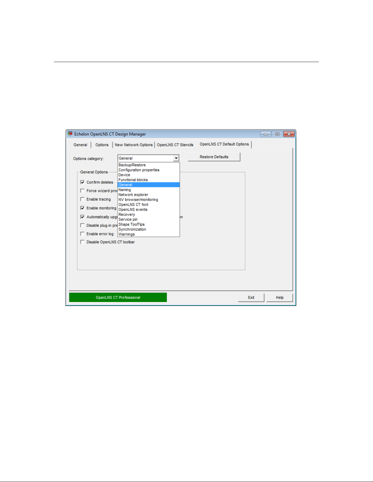
the list and then click Delete (the stencil file is not deleted).
OpenLNS CT Default Options
You can use the OpenLNS CT Default Options tab to set the OpenLNS CT default properties for the
new networks you create. This tab contains a list of OpenLNS CT options categories such as options
for configuration properties, devices, functional blocks and for backing up and synchronizing the
OpenLNS CT network database. The default options you set will be applied to each new OpenLNS
CT network you create. Once you create a new network, you can change any of the default options in
the OpenLNS CT drawing by clicking Add-ins, clicking OpenLNS CT, and then clicking OpenLNS
CT Options.
Click Restore Defaults to reset the options and values in the currently displayed options category to
their defaults.
You can set the default options for new networks in the following options categories:
• Backup/Restore
• Configuration Properties
• Device
• Functional Blocks
• General
• Naming Options
• Network Explorer
• NV Browser/Monitoring
• OpenLNS Events
• OpenLNS CT Font
• Recovery
• Service Pin
• SmartShape ToolTips
OpenLNS CT User’s Guide 37
Page 54

• Synchronization
• Warnings
Appendix A details the defaults you can set under each network properties options category.
Setting Up a Network Interface
To attach your OpenLNS CT computer to a LONWORKS network, you must define and configure an
OpenLDV 4.0-compatible network interface or an IP-852 network interface before starting OpenLNS
CT. Network interfaces include the following:
• RNIs: SmartServer, i.LON 100 Internet Server, i.LON 600 IP-852 Router, and i.LON 10 Ethernet
Adapter.
• IP-852 network interfaces: SmartServer (with IP-852 routing option), i.LON 100 Internet Server
(with IP-852 routing option), and i.LON 600 IP-852 Router.
• Local USB network interfaces: U10/U20 USB network interfaces.
• Local PC card network interfaces: PCC-10 and PCLTA-10, 20, and 21 PCI network interfaces
(32-bit versions of Windows only).
• Serial network interface: SLTA-10 serial interface (32-bit versions of Windows only).
You can use the L
these OpenLDV 4.0 network interfaces.
ONWORKS Interfaces application in the Control Panel to define, configure, and test
Optimizing Network Interface Performance
To optimize the performance of OpenLNS CT when your OpenLNS CT computer is attached to a
ONWORKS network, use an OpenLNS high performance network interface (RNI, U10/U20 USB
L
network interface, IP-852 network interface, or other network interface with a Layer 2 MIP), if
available. If you are using a PL-20 power line channel or another slow channel, you can use a legacy
interface to limit network overhead (a high performance network interface may saturate the channel).
Using an IP-852 Network Interface
You can use an IP-852 channel to implement a LONWORKS control network ove r a n IP ne t work and
integrate multiple native L
channel as a backbone. If you are attaching your OpenLNS CT computer to an IP-852 channel, you
can set up an IP-852 interface and create the IP-852 channel following these steps:
1. Ensure that all of your IP-852 devices (for example, the OpenLNS Server computer, one or more
OpenLNS CT computers, and one or more IP-852 routers) all have static IP addresses or have
dynamic IP addresses that do not change. A static IP address is an address that is not dynamically
assigned by a DHCP server.
2. Create an IP-852 interface on each computer that is to be connected to the IP-852 channel. This
may include the OpenLNS Server computer and one or more OpenLNS CT computers. To create
an IP-852 interface, follow these steps on each of the computers:
a. Open the L
ONWORKS networks into one large network that uses a high-speed IP-852
ONWORKS Interfaces application in the Control Panel.
b. Click the IP-852 tab.
c. Click Interface, point to Add, and then either click IP-852 Interface or click New Interface
and then click IP-852 in the Select Interface Type dialog.
d. The Add Network Interface Wizard dialog opens.
e. Specify the name of the new IP-852 network interface; the IP address, port, and channel
timing parameters; and authentication parameters. Click OK.
38 Getting Started
Page 55

For more information on creating IP-852 network interfaces, see the L
ONWORKS Interfaces
online help file.
3. Define the IP-852 channel and devices in the IP-852 Configuration Server. To do this, follow
these steps:
a. Click Start on the taskbar, point to Programs, point to Echelon IP-852 Configuration
Server, and then click Echelon IP-852 Configuration Server.
b. Click Channel, and then click New Channel. Enter a name for the new IP-852 channel.
c. Right-click the new IP-852 channel you just created and then click New Device. Enter a
name for the new device.
d. Right-click the new device and then click Device Properties. Enter the IP address for the
device.
e. Repeat steps c and d for each OpenLNS Server computer, OpenLNS CT computer, and
IP-852 router on the IP-852 channel.
OpenLNS CT User’s Guide 39
Page 56

The devices on the IP-852 channel will not be fully commissioned until you run OpenLNS
applications such as the OpenLNS Server or OpenLNS CT on each of the OpenLNS Server or
OpenLNS CT computers. For more information, see the IP-852 Channel User’s Guide.
Creating and Opening OpenLNS CT Networks
An OpenLNS CT network consists of an OpenLNS CT drawing and an OpenLNS network database.
OpenLNS CT provides several ways to create an OpenLNS CT network, including the following
methods:
• Create a new OpenLNS CT network design. Use this method if you are engineering a new
network, or if you want to redo the logical design of an existing network.
• Use an existing OpenLNS database to create an OpenLNS CT drawing. Use this method to use
OpenLNS CT with a network that was previously installed with an OpenLNS application other
than OpenLNS CT.
• Create an OpenLNS CT network design from an existing physical network, which creates a new
OpenLNS network database and an OpenLNS CT drawing. This method is called network
recovery. Use this method if the network is operational and was originally installed with an
application not based on OpenLNS or was self-installed. You can also use this method with a
network that was previously installed with an OpenLNS application, but does not have its original
network database. OpenLNS CT can recover a network wi t ho ut c han gi n g the de vi ce ap pl i cat i ons
or network configuration. See
Networks, for more information on how to use network recovery and for a summary of the
limitations of network recovery.
• Copy an existing OpenLNS CT network design. Use this method to create a new network that is
similar to an existing network.
Creating an OpenLNS CT Network Design
Recovering an OpenLNS CT Network in Chapter 7, Maintaining
You can create a new OpenLNS CT network design to engineer a new network or to redo the logical
design of an existing network. To create a new network design, you must use OpenLNS CT as a local
client (OpenLNS CT is running on the same computer as the OpenLNS server).
40 Getting Started
Page 57
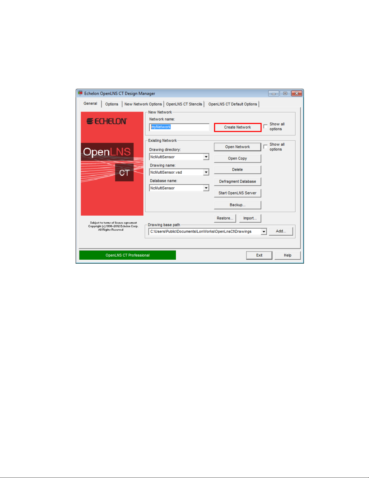
To create a new OpenLNS CT network, follow these steps:
1. Click Start on the taskbar, point to Programs, point to Echelon OpenLNS CT, and then select
OpenLNS CT. The OpenLNS CT Design Manager opens.
2. Under New Network, enter the name of the network in the New Network box, or accept the
default network name.
3. Click Create Network to create the new network. Visio starts.
• When you initially start Visio 2010, a message opens informing you that Visio must activated.
Click OK and follow the activation instructions.
• When you initially attempt to create a network, a message opens informing you that Visio
must be launched and initialized so that it can work with OpenLNS CT.
• In addition, a warning opens asking you if you want to enable macros, which are required for
OpenLNS CT to function. Click Enable Macros. See
Working with Digital Signatures for
more information.
4. If you selected the Show all Options check box under the New Network box in the OpenLNS
CT Design Manager, or you cleared the check boxes for skipping the network interface,
management mode, and plug-in options pages of the Network Wizard in the New Network
Options tab, the Naming dialog in the Network Wizard opens. Otherwise, you can skip to step 6.
OpenLNS CT User’s Guide 41
Page 58

Tips:
• You can click Finish at any point in the Network Wizard. Doing so will skip the subsequent
series of pages, and your new OpenLNS CT network design will be created using the current
settings in the New Network Options tab of the OpenLNS CT Design Manager.
• By default, the subsequent pages in the Network Wizard will appear each time you re-open
the OpenLNS CT drawing. Select the Skip This Prompt when Re-opening this Drawing
check box on any of the pages you want to skip when re-opening the drawing.
• You can change any options you set in the Network Wizard in the OpenLNS CT drawing.
Open the OpenLNS CT menu, click Network Properties, and then click the tab containing
the options you want to modify.
5. Edit the following information as required:
Network Name D isplays the network name. By default, this is the current name in
the Network Name box under New Network in the General tab of
the OpenLNS CT Design Manager. The default network name is
incremented if a naming conflict exists.
You can change the name of the network. The name must be unique
to the network database, and it can have a maximum of 16
characters. The network name in the Network Database Path and
Network Drawing Path fields will automatically be updated to
match the name you specify.
Recover Database
from Network
Opens the OpenLNS Database Recovery Wizard after completing
the Network Wizard. You can use the recovery wizard to create a
new OpenLNS CT drawing and network database from an existing
operational network.
42 Getting Started
Page 59

4Recovering an OpenLNS CT Network in Chapter 7, Maintaining
See
Networks, for more information.
Network Database
Path
Specifies the folder that will contain the network database. By
default, the database path is
C:\Users\Public\Documents\LonWorks\OpenLnsCt\Databases\
<network name>.
You can specify a different to place the OpenLNS CT network
database; however, the network name in the database path must
match the one in the Network Name box.
Network Drawing
Path
Specifies the folder that will contain the OpenLNS CT drawing. By
default, the drawing path is
C:\Users\Public\Documents\LonWorks\OpenLnsCt\
Drawings\<network name>.
You can specify a different to place the OpenLNS CT drawing;
however, the network name in the drawing path must match the one
in the Network Name box.
Network Description Contains an optional description of the network being created. This
field has no effect on network operation, but it can provide
additional documentation for as-built reports.
6. Click Next. The Network Interface dialog opens.
7. If your OpenLNS CT computer is attached to the physical network and you want OpenLNS CT to
communicate with the physical devices, select Network Attached. If you select this option and
you have more than one network interfaces in your computer, select the name of the OpenLDV 4.0
or IP-852 network interface under Network Interface Name.
OpenLNS CT User’s Guide 43
Page 60

Notes:
• The network interface you select must already have been defined and configured, as described
in Setting up a Network Interface.
• For OpenLNS CT to communicate on an IP-852 channel, the OpenLNS CT computer must be
configured as an IP-852 device on the target channel using the IP-852 Configuration Server.
If an IP-852 device name has not been defined, create one in the
as described in
Using an IP-852 Network Interface earlier in this chapter.
IP-852 Configuration Server
8. Click Next. If you specified that OpenLNS CT computer is attached to the physical network, the
OnNet/OffNet dialog opens. If it is not attached, the Plug-In Registration dialog opens and you
can skip to step 11.
9. Select when changes made in your OpenLNS CT drawing are sent to the physical devices on the
network. You have two choices:
• OnNet. Changes to the OpenLNS CT drawing are sent immediately to the physical devices
as you make the changes. Select OnNet if you are commissioning an engineered system or if
you are working on any phase of an ad-hoc system.
• OffNet. Changes to the OpenLNS CT drawing are saved in the netw ork database and then
sent to the physical devices once OpenLNS CT is set OnNet. Select OffNet if you are
designing an engineered system. You can make real-time changes to network variables when
OpenLNS CT is OffNet once you have commissioned devices with OpenLNS CT OnNet.
You can read and make changes to configuration properties while OpenLNS CT is OffNet,
but changes will not be propagated until you set OpenLNS CT OnNet or you manually
propagate them (by right-clicking a device, pointing to Commissioning, and selecting
Propagate CP Values to Device on the shortcut menu).
Select this Skip the Prompt check box if you want the Network Wizard to skip the
Management Mode page each time you open the OpenLNS CT network. If the Show all
Options check box under Existing Networks in the OpenLNS CT Design Manager General
tab is selected, the prompt will appear regardless if this check box is selected.
44 Getting Started
Page 61

10. Click Next. The Plug-In Registration dialog opens.
11. Use the following commands to register, deregister, enable, and disable plug-ins in your OpenLNS
CT network.
Register Adds a plug-in to the Pending list, indicating that the plug-in is to be
registered. A plug-in must be registered for it to be available within
OpenLNS CT.
This button is available when a plug-in listed under any category or a
category label (except Pending) is selected. If a category label is
selected, all the plug-ins under it will be registered.
Deregister Adds a plug-in to the Pending list, indicating that the plug-in is to be
deregistered. Once a plug-in is deregistered, it is no longer available
within OpenLNS CT.
This button is available when a plug-in li st e d un der Already
Registered is selected, can be deregistered, and supports being
deregistered.
Enable Adds a plug-in listed under Disabled to the Pending category,
indicating that the plug-in is to be enabled. You can enable a plug-in
that you previously disabled.
This button is available when a plug-in li st e d un der Disabled or the
Disabled category label is selected. If the Disabled category label is
selected, all the plug-ins under it will be enabled.
Disable Adds a plug-in listed under Already Registered or Not Registered to
the Pending category, indicating that the plug-in is to be disabled.
You can disable a plug-in to prevent OpenLNS CT from prompting
you to register the plug-in.
This button is available when a plug-in li st e d un der Already
OpenLNS CT User’s Guide 45
Page 62

Registered or Not Registered or either of the category labels is
selected. If the Already Registered or Not Registered category label
is selected, all the plug-ins under the selected category label will be
disabled.
Remove Removes a plug-in from the Pending list. This button is available
when a plug-in listed under Pending or the Pending category label is
selected. If the Pending category label is selected, all the plug-ins
under it will be removed.
Skip this Prompt when
Re-opening Drawing
Select this check box if you want the Network Wizard to skip the
Plug-In Registration page each time you open the OpenLNS CT
network. If the Show all Options check box under Existing
Networks in the OpenLNS CT Design Manager General tab is
selected, the prompt will appear regardless if this option is selected.
Register all New
Plug-ins when
Re-opening this
Drawing
Select this check box if you want new plug-ins in the plug-in
directory to be automatically registered each time you open the
OpenLNS CT drawing.
New plug-ins must be registered with Windows. The installation
program for the plug-ins typically does this automatically. If you are
designing your own plug-ins see the OpenLNS Plug-in Framework
User’s Guide for more information on how to create plug-ins and
register them with Windows.
Continue with
Advanced Options
Opens and lets you set options in the authentication, domain
definition, timing, and resource file language pages in the Network
Wizard. See
4Recovering an OpenLNS CT Network in Chapter 7,
Maintaining Networks, for setting the options in these pages.
12. Click Finish to open your new OpenLNS CT drawing.
13. If you are creating or opening an OpenLNS CT network for the first time, a message opens
informing you that the drawing being opened contains macros from the Echelon Corporation, and
asking you if you would like to enable macros for this drawing. Verify that the macros were
signed by Echelon Corporation, and then enable macros, which is required for using OpenLNS
CT. Set Always Trust Macros from this Source to automatically enable macros for all
OpenLNS CT drawings that are signed by Echelon
Working with Digital Signatures
Visio drawings can have VBA code associated with them through the use of macros and ActiveX
objects. Visio drawings that use this capability use Microsoft VBA signatures to provide security from
VBA viruses. Each time you create an OpenLNS CT network design, the template that you selected in
the OpenLNS CT Design Manager (L
This template uses VBA macros to implement the network drawing’s L
template and all Visio drawings created from it are signed by the Echelon Corporation.
Network drawings created with LonMaker releases before 3.1 will not have a digital signature.
Network drawings created with LonMaker Turbo Editions and LonMaker 3.1 or later may have
expired digital signatures. In addition, you can cause an OpenLNS CT drawing to lose its Echelon
signature by adding VBA code to it. This can happen if you add an ActiveX object or VBA code to
the OpenLNS CT drawing. Once a network drawing has lost its signature, it cannot get it back
automatically. If you have lost Echelon’s signature on a network drawing, you have three op tions: (1)
ignore the macro warnings as described in the next paragraph; (2) disable macro warnings as described
in the next paragraph; or (3) sign the drawing with your compan y’s digital signature as described at
http://office.microsoft.com/en-us/excel-help/digitally-sign-a-macro-project-HA001231781.aspx.
46 Getting Started
ONWORKS.vst by default) is used to create the network drawing.
ONWORKS functionality. This
Page 63

If an OpenLNS CT drawing does not have a digital signature, you will see the macro warning dialog
and will have to enable macros every time the network drawing is opened, provided Visio’s macro
security is set to medium (the default). In order to change Visio’s macro security, open the Tools
menu, point to Macro and then select Security. A dialog opens allowing you to select Low, Medium,
or High security.
• If you select Low security, you will never see the macro warning.
• If you select Medium security, you will be prompted to enable macros for unsigned network
drawings or network drawings signed by companies that have not been added to the trusted
signatures list.
• If you select High security, macros will automatically be disabled (and OpenLNS CT will not
function) for unsigned network drawings, and you will be prompted to enable macros for network
drawings signed by companies that have not been added to the trusted signatures list.
Visio’s security level is persistent. When you change Visio’s security level, it will be the security level
for Visio every time it is started until you change it again.
Tip: If your drawing contains ActiveX controls, change the security setting to Low. Otherwise, Visio
will prompt you each time the drawing is opened as to whether to activate the controls.
Creating an OpenLNS CT Network from an Existing OpenLNS Database
You can create a new OpenLNS CT network design by opening an OpenLNS network database that is
not already associated with a drawing. OpenLNS CT will then create a drawing for the database. You
can use this procedure to import an existing network into OpenLNS CT when the network was created
with an OpenLNS application other than OpenLNS CT. To create a new OpenLNS CT network from
an existing OpenLNS network database, you must use OpenLNS CT on a local client.
To create a new OpenLNS CT network design from an existing OpenLNS database, follow these steps:
1. Click Start on the taskbar, point to Programs, point to Echelon OpenLNS CT, and then select
OpenLNS CT. The OpenLNS CT Design Manager opens.
2. Under Existing Network, select which database you want to open in the Database Name list and
then select <none> in the Drawing Directory list. A Create Drawing command will appear in
place of the Open Network command.
OpenLNS CT User’s Guide 47
Page 64

3. Click Create Drawing. Visio starts and the Naming dialog of the Network Wizard opens.
4. Specify the folder that will contain the OpenLNS CT drawing in the Network Drawing Path box.
The folder must have the same name that opens in the Network Name box, but it may be
contained within another folder. The Network Name and Network Database Path boxes are
read-only, as these settings are determined by the OpenLNS network database. Click Next. The
Network Interface dialog opens.
48 Getting Started
Page 65
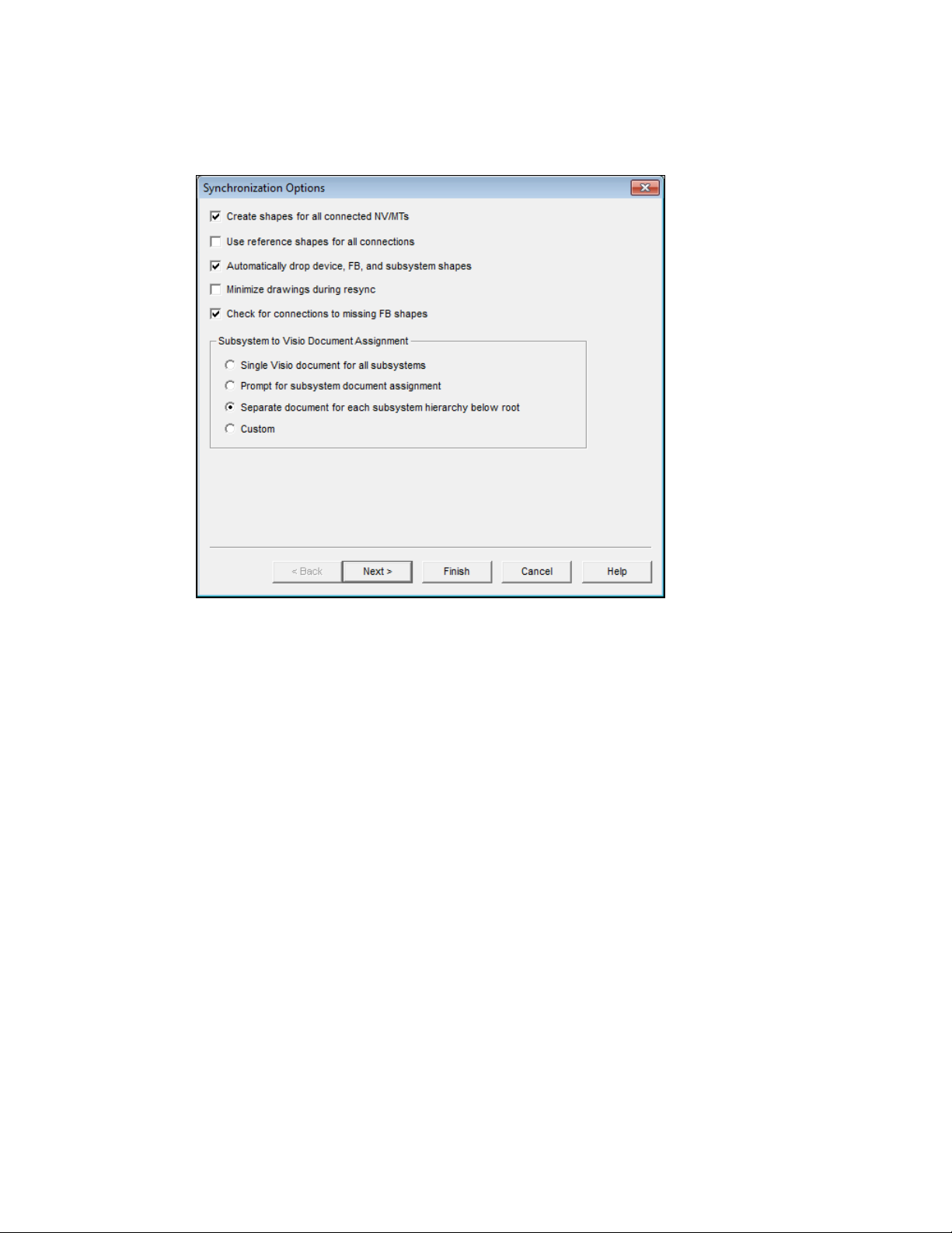
5. Following steps 7 through 9 of Creating a New OpenLNS CT Network Design, select whether
OpenLNS CT is attached to the network, and if it is attached, select the management mode (OnNet
or OffNet). Click Finish. The Synchronization Options dialog box opens.
6. Select the desired synchronization options and subsystem assignments.
Create Shapes for all
Connected NVs/MTs
Adds SmartShapes to functional blocks for all connected network
variables or message tags created by the resynchronization.
If this check box is cleared, OpenLNS CT will use generic
connections when possible. It will still create network variable or
message tag SmartShapes for connections to supernodes and for
those functional blocks that already contain network variable or
message tag SmartShapes.
Use Reference
Shapes for all
Connections
Represents all network variable connections created by the
resynchronization with reference connectio n SmartShapes.
If this check box is cleared, OpenLNS CT will use standard
connection SmartShapes for connections for net w or k vari able hubs
and targets located in the same subsystem. Reference connection
SmartShapes are always used for connections that span subsystems.
Automatically Drop
Device, FB, and
Subsystem Shapes
Automatically adds SmartShapes to the drawing for all devices,
functional blocks, and subsystems created by the resynchronization.
If this check box is cleared, OpenLNS CT will prompt the user to
select whether a SmartShape should be added for a device,
functional block, or subsystem created by the resynchronization.
Minimize Drawings
during Resync
Minimizes all the drawings in the OpenLNS CT network during the
resynchronization. This speeds up the resynchronization as it
reduces the time Visio spends updating the drawings.
Check for
Connections for
Enables OpenLNS CT to check for connections to functional blocks
that are in the OpenLNS database but not represented by a
OpenLNS CT User’s Guide 49
Page 66

Missing FB Shapes SmartShape in the OpenLNS CT drawing.
Subsystem to Visio
Document
Assignment
Select in which Visio drawing file to place the subsystems in your
network. You have four choices:
• Single Visio Document for all Subsystems. Places all
subsystems in a single Visio document.
• Prompt for Subsystem Document Assignment. Prompts you
to specify the Visio document for each subsystem.
• Separate Document for each Subsystem Hierarchy below
Root. Places each subsystem hierarchy below the top-level
subsystem in a separate, new Visio document.
• Custom. Opens the Subsystem Document Assignment d i al og.
In this dialog, you specify the Visio document for each
subsystem.
7. Click Next. If you selected the Automatically Drop Device, FB, and Subsystem Shapes check
box, the Select Stencil dialog box opens. If you cleared this check box, skip to step 9.
8. Select the stencils that you want to be scanned for master SmartShapes.
• To add a stencil, click Add Stencil, select the desired Visio stencil file (.vss), and then click
Open or double-click the stencil.
• To remove a stencil, select the desired stencil and then click Remove. You can also re-order
the stencil positions by selecting a stencil and clicking Move Up or Move Down. Click
Finish.
OpenLNS CT will then search, in order, all the listed stencils. When objects are found within
the database that are not already represented in the drawing, OpenLNS CT scans the listed
stencils and automatically adds the appropriate SmartShape to the drawing. If the particular
master SmartShape for an object is not found, an appropriate generic SmartShape (a
50 Getting Started
Page 67

ONWORKS Device SmartShape, for example) will be used. After OpenLNS CT is done
L
scanning stencils, the Synchronization Status dialog box opens.
9. You can monitor the progress of the resynchronization. When the resynchronization is complete,
click OK to open your OpenLNS CT network.
Copying an OpenLNS CT Network Design
You can create a new OpenLNS CT network design by copying an existing one. You can use this
procedure to reuse the drawings, options, plug-ins, master SmartShapes, and device templates of an
existing network design. You can also use this procedure to reduce the time required to create a new
network. To do this, create an empty network design with all your desired plug-ins already registered,
and then copy the empty network design for each new network that you create. To copy an existing
OpenLNS CT network design, you must use OpenLNS CT on a local client
To create a new OpenLNS CT network design by copying an existing one, follow these steps:
1. Click Start on the taskbar, point to Programs, point to Echelon OpenLNS CT, and then select
OpenLNS CT. The OpenLNS CT Design Manager opens.
2. Choose an OpenLNS CT network to copy. Under Existing Network, select a drawing directory
from the Drawing Directory list, and then select the network you want to copy from the Drawing
Name list. Click Open Copy. A message opens prompting you to confirm that you want to open
a copy of the selected network, which will create copies of the OpenLNS network database and all
the drawings in the network.
3. Click Yes. The Network Wizard opens and the Naming page opens
4. Follow steps 5–11 in Creating an OpenLNS C T Net w ork D e sign. By default, the options selected
in the existing network will be used in your new network; however, you can change any option.
When you have completed the Plug-In Registration page, click Next. The Network Properties:
Domain dialog box opens.
OpenLNS CT User’s Guide 51
Page 68

5. A new random domain ID is generated. To use a specific domain ID, clear the Use Randomly
Generated Domain ID check box and enter your ID in hexadecimal format in the Domain ID
box. Click Finish.
6. If you are copying a network created with OpenLNS CT, your new OpenLNS CT network will
open and you can skip the remaining steps.
7. If the existing OpenLNS CT network design you are cop ying was created in a previous version of
LonMaker Turbo Editions (or earlier versions of the LonMaker tool), the Synchronize OpenLNS
CT for Windows Drawing dialog box opens. This is because the OpenLNS CT SmartShapes in
the drawing need to be updated to reflect the current OpenLNS CT.
8. In the Synchronize OpenLNS CT for Windows Drawing dialog box, the Update Shapes to
Current OpenLNS CT Version check box will be selected by default. Select any other desired
synchronization options and click Next. The Choose Synchronization Scope dialog box opens.
9. Accept the defaults and click Next. The Choose Shapes and Items to Update dialog box will
appear.
10. Accept the defaults and click Finish. The Synchronization Status dialog box opens as the
synchronization process begins.
11. The Synchronization Status dialog box displays the progress of the synchronization. Once
“Synchronization Complete” opens, click OK to open your OpenLNS CT network design.
For more information about the synchronization options in the preceding dialog boxes, see
Manual
Network Resynchronization in Chapter 7, Maintaining Networks.
Notes: If you open the copy of the OpenLNS CT network with OpenLNS CT set OnNet, a message
opens reminding you that the copy of the OpenLNS CT network should not be attached to the physical
network associated with the original. This is because the devices and routers will be updated to match
the new network database. Verify that OpenLNS CT is not attached to the original network and then
click Yes to proceed with your OpenLNS CT set OnNet. Click No to return to the Management Mode
page and set OpenLNS CT OffNet.
52 Getting Started
Page 69
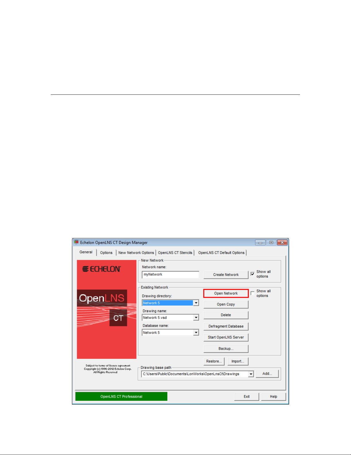
Any devices you created and commissioned in your original network will have the same Neuron IDs in
the copied version. To avoid conflicts, make sure the domain IDs of the original and copied OpenLNS
CT network designs are unique, or make sure that the copied OpenLNS CT network design is not
attached to the physical network associated with the original version when you are using it.
Monitoring will be disabled in the copy of the OpenLNS CT network. To enable monitoring,
right-click a clear space in the drawing page and click Enable Monitoring. See Chapter 6,
Monitoring
and Controlling Networks, for more information on how to monitor and control application devices.
Opening an OpenLNS CT Network Design
To open an existing OpenLNS CT network, follow t hese steps:
1. Click Start on the taskbar, point to Programs, point to Echelon OpenLNS CT, and then select
OpenLNS CT. The OpenLNS CT Design Manager opens .
2. Choose the OpenLNS CT network you want to open. Under Existing Network, select the desired
drawing directory from the Drawing Directory list, and then select the network you want to open
from the Drawing Name list. For networks with multiple drawings files, you can select any of the
drawing files associated with the network.
3. To skip any or all of the pages in the Network Wizard when opening the existing network, clear
the Show all Options check box under the Existing Network box. The pages in the Network
Wizard will be skipped when you re-open the network provided that you previously selected the
check box at the bottom of the page (the Automatically Determine Server Location check box
for the Server Location page and the Skip This Prompt check box for all other pages). You can
also select the options to skip the pages in the Network Wizard in the OpenLNS CT drawing (to
do this, click Add-ins, click LonWorks Network, and click Network Properties). You cannot
skip the User Logon page if you have defined user profiles for the network (see
this chapter for more information).
4User Profiles in
4. Click Open Network.
OpenLNS CT User’s Guide 53
Page 70

5. If you are opening an Op enLNS CT network after s tarting OpenLNS CT for the first time, a
message may appear asking you if you want to enable macros. You must enable macros for
OpenLNS CT to function. See
Working with Digital Signatures for more information.
6. Visio starts, your OpenLNS CT drawing opens, and the Server Location page of the Network
Wizard opens (unless you selected the Automatically Determine Server Location check box at
the bottom of this page when you previously opened the network).
By default, each subsequent page in the Network Wizard will appear every time you open the
OpenLNS CT drawing unless you previously selected the Skip This Prompt check box on the
page from the Network Wizard or from the Network Properties dialog in the drawing.
Tip: You can click Finish at any point in the Network Wizard to skip the subsequent series of
pages and open your OpenLNS CT network. Your OpenLNS CT network will be opened using
the settings in the Network Properties dialog in the drawing at the time it was last saved.
7. Under Server Location, select the client type of the computer on which OpenLNS CT is running.
See OpenLNS CT Client Types for more information on each of these client types.
• Select Local if OpenLNS CT is running on the same computer as the OpenLNS Server.
• Select Remote Full Client if OpenLNS CT is running on a computer different than the
OpenLNS Server and the OpenLNS CT computer is attached to a L
ONWORKS channel
through an IP-852 channel.
• Select Remote Lightweight Client if OpenLNS CT is running on a computer different than
the OpenLNS Server and the OpenLNS CT computer communicates with the OpenLNS
Server over TCP/IP.
Select the Automatically Determine Server Location check box to have OpenLNS CT
automatically determine the location of the OpenLNS Server when you re-open your
OpenLNS CT network. If this check box is cleared, OpenLNS CT will prompt you to select
the server location each time you open the drawing.
54 Getting Started
Page 71

8. Click Next. The Network Interface page opens, unless the Skip this Prompt check box was
previously selected. Follow steps 7–12 in Creating an OpenLNS CT Network Design. By default,
the options previously selected for the network will be used; however, you can change any option.
Note: You may open multiple OpenLNS CT network designs by repeating the preceding steps.
Each OpenLNS CT network design that you open will have its own instance of Visio.
OpenLNS CT Client Types
The OpenLNS CT client type determines the location of OpenLNS CT in relation to the OpenLNS
server. OpenLNS CT supports three client types: local client, remote full client, and remote
lightweight client.
Local Client
A local client is an OpenLNS CT computer that is also running OpenLNS Server. In this
configuration, a local network interface is attached to the OpenLNS Server computer, and OpenLNS
CT uses the local network interface to communicate directly with the physical network. The following
figure demonstrates how OpenLNS CT connects to the physical network when it is running as local
client.
A local client can also be configured as a local IP client. In this configuration, the OpenLNS CT
computer is attached to an IP-852 channel and communicates remotely with the network through an
IP-852 router (SmartServer [with IP-852 routing option], i.LON 100 Internet Server [with IP-852
routing option], or i.LON 600 IP-852 Router). OpenLNS CT is still considered a local client because
is it running on the same computer as the OpenLNS Server.
OpenLNS CT User’s Guide 55
Page 72

Remote Full Client
A remote full client is an OpenLNS CT computer that communicates with the OpenLNS Server
(running on a separate computer) over a L
computer uses a network interface to communicate with the network (for example, a U10/U20 USB
network interface or PCC-10, PCLTA-20, or PCLTA-21 network interface card). As a remote full
client, network management tasks performed by OpenLNS CT are routed through the OpenLNS
Server, but monitoring and controlling tasks are sent directly to the network.
One or more OpenLNS CT computers and the OpenLNS Server may also be connected to the network.
ONWORKS channel. In this configuration, the OpenLNS CT
56 Getting Started
Page 73
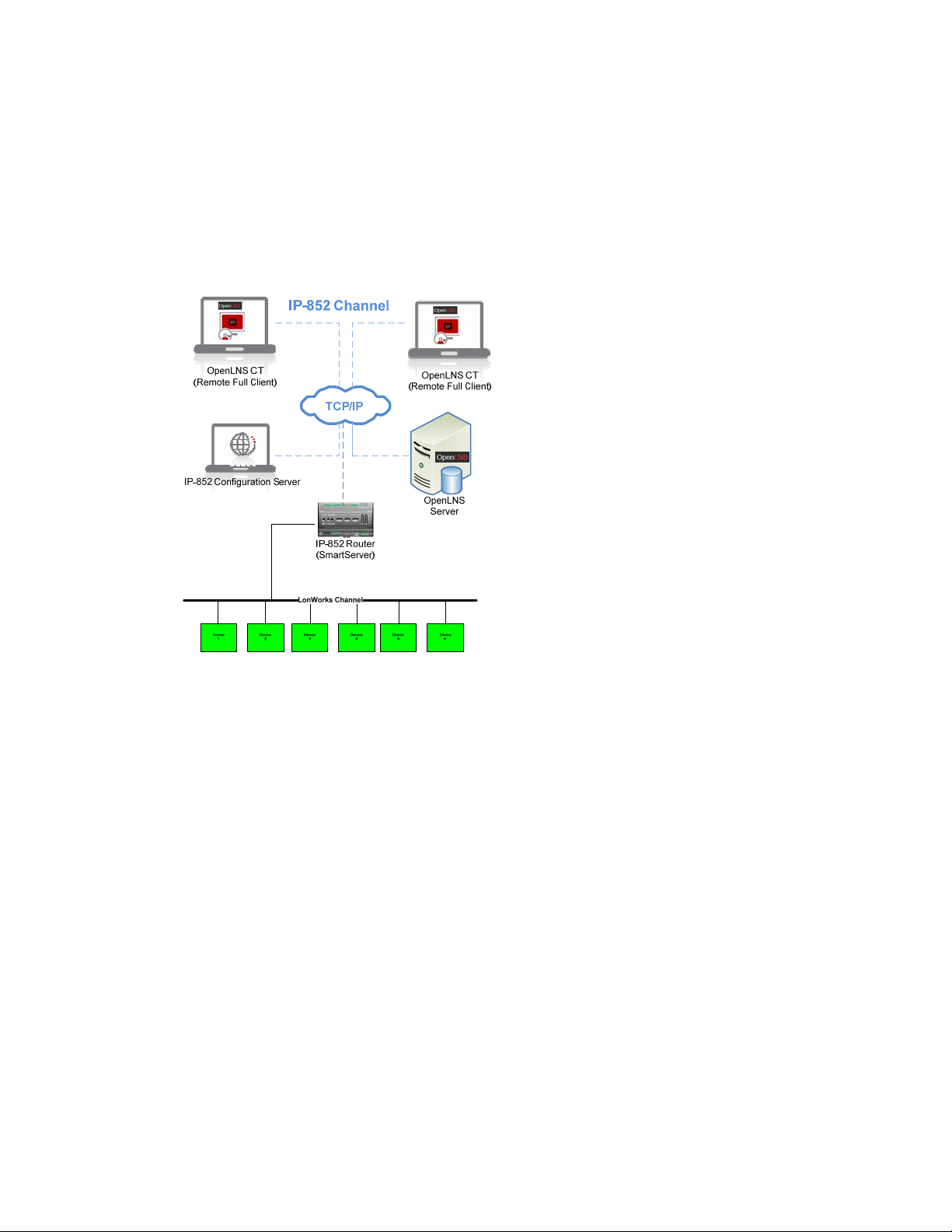
The following example demonstrates a scenario in which the OpenLNS CT computers communicate
with the OpenLNS Server and the network over an IP-852 channel. The OpenLNS computers directly
route management tasks to the network via an IP-852 router.
The IP-852 Configuration Server creates virtual channels that direct packet traffic and enable the
IP-852 devices (OpenLNS CT computers, the OpenLNS Server, the IP-852 router, and other IP-852
devices) to communicate with each other over the TCP/IP network. To create the IP-852 channel, you
must use the IP-852 Configuration Server to add and configure all the IP-852 devices to the network.
For more information on using the IP-852 Configuration Server to create IP-852 channels, see
Using
an IP-852 Network Interface earlier in this chapter.
To use OpenLNS CT on a remote full client follow these steps:
1. Prepare for remote operations.
a. Copy any custom stencils that you will need to the OpenLNS CT drawing folder on the
OpenLNS Server computer.
b. Back up the OpenLNS CT drawing for the network you will be us ing and all other files in the
drawing directory. See
Backing Up an OpenLNS CT Network Design in Chapter 7,
Maintaining Networks, for instructions.
c. Save the OpenLNS CT backup file to a shared network folder . If you do not ha ve a sha r ed
network folder, save the backup file to a CD, DVD, USB drive, floppy disk, or other storage
media.
2. Start the OpenLNS Server.
a. Click Start on the taskbar, point to Programs, point to Echelon OpenLNS CT, and then
select OpenLNS CT. The OpenLNS CT Design Manager opens.
b. Choose the OpenLNS network database you want to open from the Database Name list and
click Start OpenLNS Server.
OpenLNS CT User’s Guide 57
Page 74

c. The Echelon OpenLNS Remote Server application opens with the Network Interfaces
dialog.
d. Select the OpenLNS network interface or IP-852 network interface to be used to connect to
ONWORKS channel. An OpenLNS Server or remote client can be attached to an IP-852
the L
channel using an IP network interface, such as an Ethernet network interface card (NIC),
WiFi interface, or a modem channel with PPP software. The network interface to the
ONWORKS channel must be defined and configured before opening an existing OpenLNS
L
CT network on a remote full client. Click OK. The OpenLNS Server dialog opens.
e. The OpenLNS Server dialog displays the status for the open network. For more information
on using the OpenLNS Server, open the Help menu and click OpenLNS Server Help to view
the OpenLNS Utilities Online Help System file.
58 Getting Started
Page 75

f. To open an additional network, click Start OpenLNS Server on the OpenLNS CT Design
Manager. The OpenLNS Server window opens. Hi ghlight the next network to open. Click
Open Network. The Network Interface page opens. Select the network interface. Click OK.
Repeat this process for each additional network you want to open.
3. Copy the OpenLNS CT backup file that you created in step 1 to the remote client.
4. Start OpenLNS CT on the remote full client. Click Start on the taskbar, point to Programs, point
to Echelon OpenLNS CT, and then select OpenLNS CT. The OpenLNS CT Design Manager
opens.
5. Restore the OpenLNS CT drawings from the backup you created in step 1. See
4Restoring an
OpenLNS CT Network in Chapter 7, Maintaining Networks, for instructions. After restoring the
drawing files, a prompt opens asking whether you want to open the network drawing. Click Yes
to open the network drawing. The Network Wizard opens with the Server Location dialog.
OpenLNS CT User’s Guide 59
Page 76

6. Select Remote Full Client to access the network and then click Next. The Network Interface
page opens.
7. Follow steps 7–12 in Creating an OpenLNS C T Net w ork D e sign.
Remote Lightweight Client
A remote lightweight client is an OpenLNS CT computer that communicates with the OpenLNS Server
(running on a separate computer) via TCP/IP. As a remote lightweight client, the network
management, monitoring, and controlling tasks performed by OpenLNS CT are all routed through the
OpenLNS Server. This means that all network variable reads and writes are routed through the
OpenLNS Server, which can create bottlenecks in the OpenLNS Server if multiple remote lightweight
clients are monitoring and control multiple data points simultaneously. A remote lightweight client
can connect to the network without an IP-852 router.
60 Getting Started
Page 77

To use OpenLNS CT on a remote lightweight client follow these steps:
1. Prepare for Remote Operations.
a. Copy any custom stencils that you will need to the OpenLNS CT drawing folder on the
OpenLNS Server computer.
b. Back up the OpenLNS CT drawing for the network you will be us ing and all other files in the
drawing directory. See
Backing Up an OpenLNS CT Network Design in Chapter 7,
Maintaining Networks, for instructions.
c. Save the OpenLNS CT backup file to a shared network folder . If you do not ha ve a sha r ed
network folder, save the backup file to a CD, DVD, floppy disk, or other storage media.
2. Start the OpenLNS Server application.
a. Ensure that the OpenLNS Server computer is not set up to go into standby mode. Standby
mode will prevent communication with remote clients.
b. Click Start on the taskbar, point to Programs, point to Echelon OpenLNS CT, and then
select OpenLNS CT. The OpenLNS CT Design Manager opens.
c. Choose the OpenLNS network database you want to open from the Database Name list and
click Start OpenLNS Server. The Network Interfaces dialog box opens.
d. Select the OpenLNS Network Interface or an IP-852 Network In terface you want to use to
connect to the L
ONWORKS channel. Click OK. The OpenLNS Server dialog opens.
3. Copy the OpenLNS CT backup file that you created in step 1 to the remote lightweight client.
4. Start OpenLNS CT on the remote lightweight client. Click Start on the taskbar, point to
Programs, point to Echelon OpenLNS CT, and then select OpenLNS CT. The OpenLNS CT
Design Manager opens.
5. Restore the OpenLNS CT drawings from the backup you created in step 1. See
Restoring an
OpenLNS CT Network in Chapter 7, Maintaining Networks, for instructions. After restoring the
drawing files, a prompt opens asking whether you want to open the network drawing. Click Yes
to open the network drawing. The Network Wizard opens with the Server Location dialog.
OpenLNS CT User’s Guide 61
Page 78

6. Select Remote Lightweight Client to access the network and then click Next.
7. If the server address is configured correctly, you can skip to step 10 , in which the User Logon
window opens. If there is a problem with the server address, or you are opening a drawing created
using LonMaker, the Selecting a Remote Network Name dialog opens.
62 Getting Started
Page 79

8. Select an OpenLNS CT network to open. If a connection to this network has already been
established, click Next, and skip to step 10. If you are accessing the selected network over an
OpenLNS/IP interface for the first time, click Add/Remove. The Remote Networks Collection
dialog box opens.
9. Under Remote Network Properties, the Address box displays the address of the OpenLNS
Server, and the Port box displays the port used for the OpenLNS/IP connection (the default is
2540, which is the default port for the OpenLNS Server). Both boxes are read-only. Click Add or
Edit to create a new remote network or modify an existing one. Click OK, select the newly
created remote network, and then click Next.
10. Follow steps 9–12 in Creating an OpenLNS CT Network Design.
Using Network Service Device SmartShapes
A network service device (NSD) is a local or remote client capable of monitoring and controlling the
network. Every OpenLNS Server and OpenLNS CT remote full client in a network may be
represented in an OpenLNS CT drawing with an NSD SmartShape. When an OpenLNS CT network is
created, it initially contains an NSD SmartShape for the OpenLNS Network Interface that represents
the OpenLNS Server.
If a remote full client is connected to a network, you can add an NSD SmartShape that represents the
remote full client to the OpenLNS CT drawing. Creating an NSD SmartShape makes that remote full
client permanent in the drawing; otherwise, OpenLNS automatically creates and deletes it each time
you open and close the network.
After you have added a network service device, you can add a virtual functional block to that NSD,
add network variables to the virtual functional block, and then connect the network variables. This
enables the NSD to monitor devices directly as described in Binding Network Variables to the Host in
Chapter 6, Monitoring and Controlling Devices. Additionally, this lets you perform the network
management tasks described in Chapter 8, Managing Networks.
To add a NSD SmartShape to an OpenLNS CT drawing, follow these steps:
1. Drag the Network Service Device SmartShape (
stencil to your OpenLNS CT drawing.
OpenLNS CT User’s Guide 63
) from the OpenLNS CT Basic Shapes
Page 80
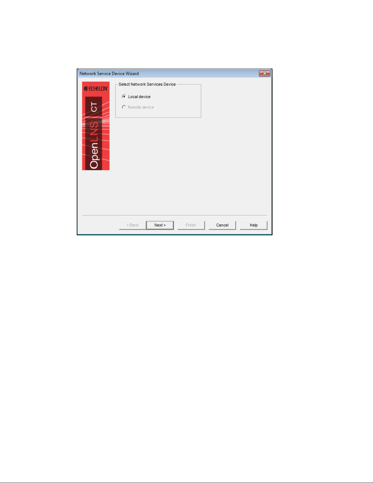
2. A dialog opens that allows you to select whether the network service device being added
represents the local NSD (only available if you are a remote client and you are using a NSD that
does not have a SmartShape associated with it) or a remote NSD.
3. If you selected Remote Device in step 2, a dialog opens which allows you to select the local or
remote network service device to be associated with this network service device SmartShape. If
there is only one network service device with no corresponding SmartShape, it will be
automatically selected.
Note: If you need to remove a NSD from the physical network, first remove the network service
device SmartShape from the drawing by right-clicking it and selecting Delete from the shortcut menu.
Listing Network Service Devices
If you are using OpenLNS CT with remote clients, you can view a list of all OpenLNS clients
connected to the network. Each client is represented by a network service device. To obtain a list of
all NSDs in a network, click Add-ins, point to LonWorks Network, and then select Network Service
Devices. The L
ONWORKS Network Service Devices dialog box opens.
64 Getting Started
Page 81

This dialog box lists all NSDs in this network, regardless of whether a SmartShape has been created
for each NSD. For each NSD, the following information is listed:
NSD Name Specifies the name of the NSD, which is assigned by the OpenLNS
Server.
Type Specifies the NSD type. This can either be NSS (the OpenLNS
Server) or NSI (a remote full client).
Device Name Specifies the NSD name in the format of <subsystem
name>.<network service device name>.
Channel Specifies the channel on which the NSD is attached.
Monitor Sets? Indicates whether monitor sets are defined on the NSD.
User Name Specifies the user name associated with the NSD. See
for more information on user names.
Application Specifies the name of the application currently active on the NSD.
If there is no application, or the application does not provide its name,
“Unknown” is displayed.
If the network service device is not responding, “No Response” is
displayed.
Click Remove to delete the selected network service device from the network. This option is generally
used to remove remote network service devices that are no longer in use, which improves the
performance of OpenLNS CT.
Click Monitor Sets to open the Monitor Sets dialog box, in which you can view and remove monitor
sets in the OpenLNS CT network. To delete a monitor set, locate the monitor set to delete from the
list, right-click the monitor set, and then click Remove on the shortcut menu.
User Profiles
Upgrading Network Service Devices
When you upgrade OpenLNS CT or switch between an OpenLNS high performance network interface
(LonTalk layer 2) and an OpenLNS network interface (LonTalk layer 5), you must upgrad e your
network service device. When you open the network and either of these conditions is detected,
OpenLNS CT will ask whether you want to upgrade. You should typically perform the upgrade.
However, if you are only using a different network interface temporarily, you may choose not to
upgrade. In this case, communication with physical devices is limited until the network is reopened
with the original network interface. If initially you choose not to upgrade the network service device
OpenLNS CT User’s Guide 65
Page 82

and decide later to upgrade, select the NSD SmartShape, right-click it, and then click Upgrade NSD
on the shortcut menu.
When moving from an OpenLNS high performance network interface (LonTalk layer 2) to an
OpenLNS network interface (LonTalk layer 5), all connections and monitor sets may not be created on
the new network interface. If this happens, a dialog displays the items that will be lost and gives you
an opportunity to cancel the upgrade.
Replacing a Local Network Service Device
When working as a remote full client, you can configure your local NSD to assume the configuration
(monitor sets, connections, and so on) of another, previously defined network service device. You can
do this by replacing a local NSD with the desired NSD SmartShape. The following conditions must be
met:
• Your current local NSD cannot have an NSD SmartShape associated with it. If it does, you must
first delete the NSD SmartShape from the drawing along with any associated functional block
SmartShapes and connections.
• The desired NSD must have a SmartShape in the drawing. If necessary, select one from the
template and drag it to the drawing.
When these conditions are met, select the desired NSD SmartShape, right-click it, and then click Make
Local NSD on the shortcut menu. You have full access to the configuration of the selected NSD.
Note: The selected NSD must not currently be in use by another remote client. If it is, performing this
operation will disconnect the other user from the network.
User Profiles
With user profiles, you can set which parts of an OpenLNS CT drawing users can access and the
actions they can perform. For example, you could have a scenario in which a system integrator has
access to the entire network and can add, delete, or change channels, routers, devices, functional blocks
and all other objects. Operators, though, would only be able to access the subsystem they are installing
and be restricted to commissioning devices and routers in that subsystem.
To enable user profiles on an OpenLNS CT drawing, you must first ass ign an administrator password.
To set the administrator password, click Add-ins, point to OpenLNS CT, select User Profiles, enter
the administrator password in the Password and Retype Password boxes, and then click Apply.
Passwords are case sensitive.
66 Getting Started
Page 83

Creating a New User Profile
To create a new user profile, follow these steps:
1. In the OpenLNS CT drawing, click Add-ins, point to OpenLNS CT, and then select User
Profiles. The User Profiles dialog box opens.
2. Enter the name of the new user name in the Name box, and the password in the Password and
Retype Password boxes. Both the user name and password are case sensitive.
OpenLNS CT User’s Guide 67
Page 84
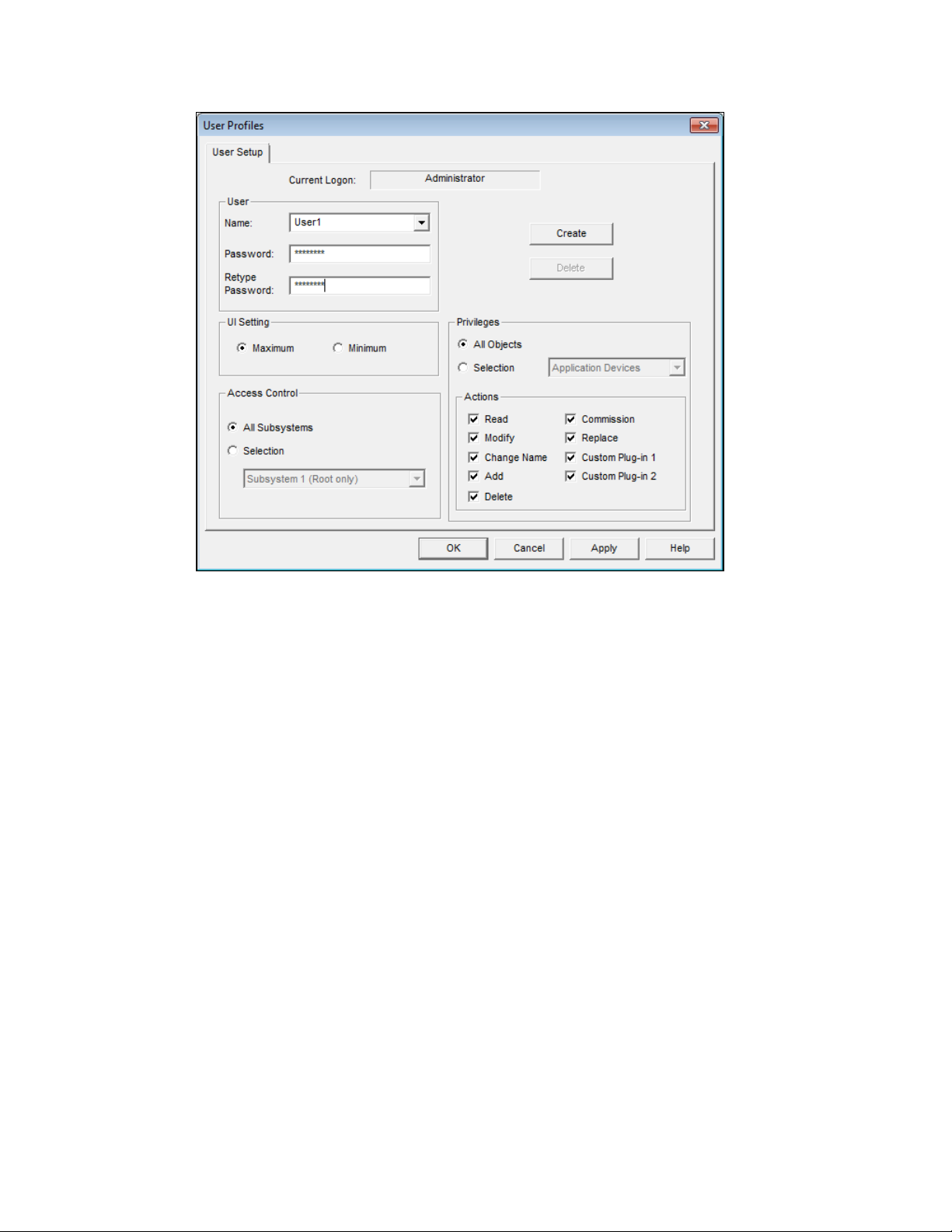
3. Set the user interface, access, and privileges of the new user.
UI Setting If you are using Visio 2003, you can select the set of OpenLNS CT
and Visio menus that will be available to the user. This option is not
available if you are using Visio 2010. If you are using Visio 2003,
you have two choices:
• Maximum. This setting provides the user a full set of toolbars,
menus, and menu items for advanced use of OpenLNS CT.
• Minimum. This setting provides the user only the basic menus,
menu items, and toolbars necessary to use OpenLNS CT.
Access Control Select the type of access the user has in the OpenLNS CT drawing.
You have two choices:
• All Subsystems. The user has unrestricted access to all of the
subsystems in the network.
• Selection. The user’s access is restricted to the selected
subsystem. This option can only be applied to the root
subsystem or any one of the subsystems one level below it. If
you select the root subsystem, the user cannot access any of the
subsystems below it.
68 Getting Started
Page 85
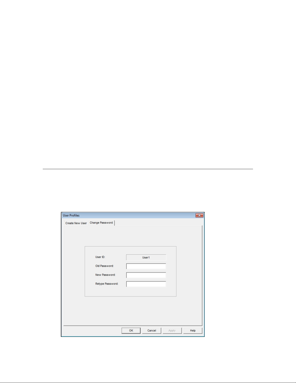
Privileges Select which actions the user can perform on objects in the
OpenLNS CT drawing.
You can set privileges for reading, modifying, changing the name,
adding, deleting, commissioning, and replacing objects, as well as
the use of plug-ins for the objects. The objects for which you can set
privileges consist of the network, subsystems, channels, application
devices, routers, functional blocks, connections, network variables,
and configuration properties.
While All Objects is selected, the privileges you set apply to all
objects. For example, to prevent this user from modifying any
object, click All Objects and then clear the Modify check box.
While Selection is selected, the privileges you set apply only to the
object specified in the Selection list. For example, to enable this
user to be able to modify functional blocks but not devices, click
Selection, select Functional Blocks, and then select the Modify
check box. Then select Application Devices from the Selection list
and clear the Modify check box.
4. Click Create if you are logged on as the Administrator; otherwise, click OK.
Note: Once the new user profile has been created, that user can open the network drawing and then
change their password or create new user profiles. A user can grant a new user only those privileges
that they have themselves.
Changing Passwords
All users can change their passwords. To change a password, follow these steps:
1. In the OpenLNS CT drawing, click Add-ins, point to OpenLNS CT, and then select User
Profiles. The User Profiles dialog box opens.
2. Click the Change Password tab.
OpenLNS CT User’s Guide 69
Page 86

3. Type the old password in the Old Password box, enter the new password in the New Password
and Retype Password boxes, and then click OK. The password will be changed.
Modifying and Deleting User Profiles
Only the Administrator can modify or delete a user profile. To modify or delete a user profile, follow
these steps:
1. In the OpenLNS CT drawing, click Add-ins, point to OpenLNS CT, and then select User
Profiles. The User Profiles dialog box opens.
2. Select a user profile to modify from the Name list.
3. To configure the user profile, change the options for the user interface, access and/or privileges,
and then click Apply. OpenLNS CT saves the changes for the selected user. If the user is
currently logged onto the network drawing from another computer, they must close and re-open
OpenLNS CT for the changes to take effect.
To delete the user profile, click Delete. A confirmation prompt opens. Click Yes to delete the
selected user.
Changing User Profiles in an OpenLNS CT Drawing
You can switch user profiles in an OpenLNS CT drawing. To change users, follow these steps:
1. In the OpenLNS CT drawing, click Add-ins, point to LonWorks Network, and then select
Network Properties. The Network Properties dialog box opens.
2. Click the Logon tab.
3. Click Change User. The Enter User Name and Password dialog box opens.
70 Getting Started
Page 87
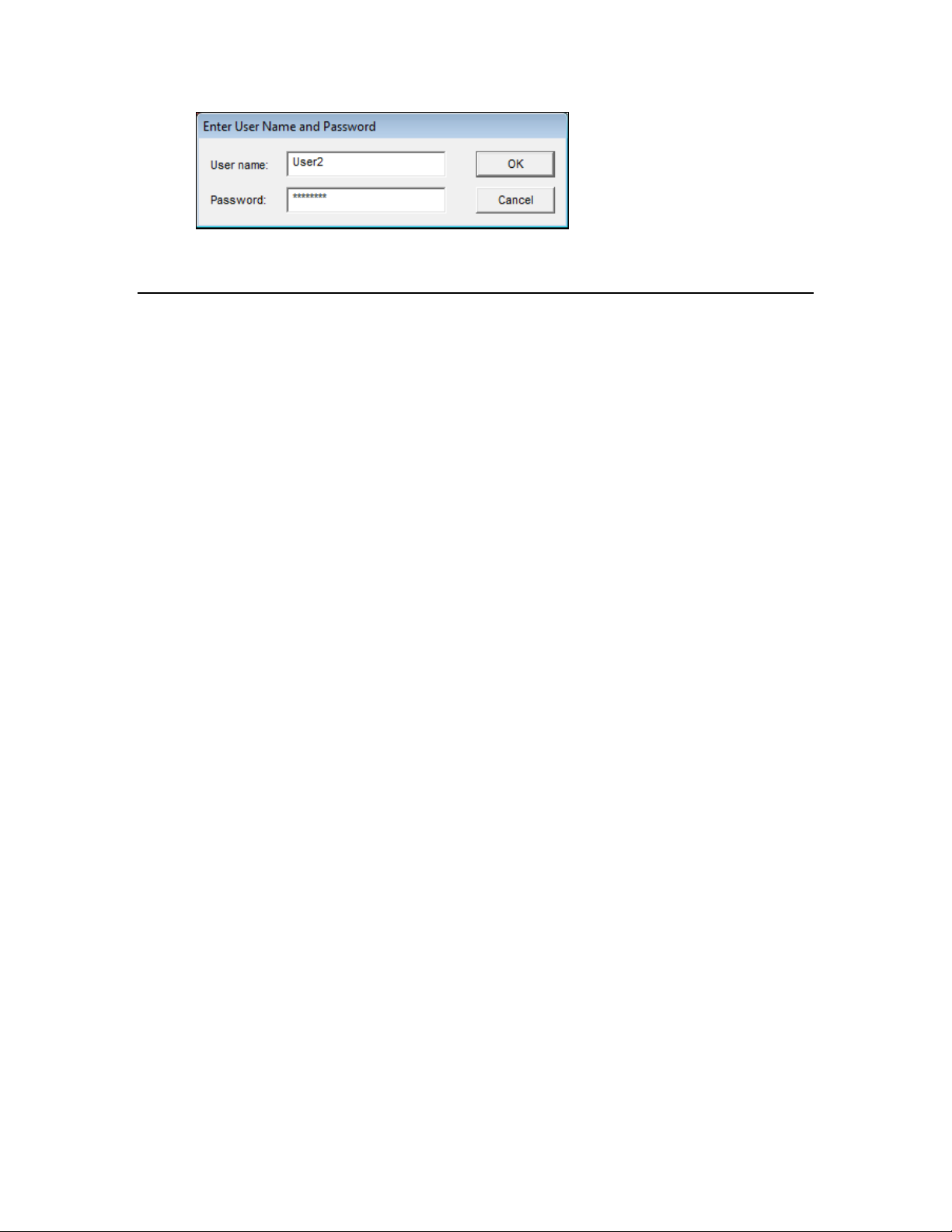
4. Enter the user name and password of the user you want to logon as.
5. Click OK. You will be logged on as the selected user.
Using OpenLNS CT Remotely with User Profiles
When you open an OpenLNS CT network on a remote client, you will be prompted for your user name
and password (provided that the administrator password has been set for the network). After logging
on to the network, you will have the same privileges as you do when working on a local client.
OpenLNS CT User’s Guide 71
Page 88

72 Getting Started
Page 89

4
Designing Networks
This chapter describes how to design a network using OpenLNS CT. It covers how to
create the following objects in an OpenLNS CT drawing: application devices,
functional blocks, network variables, routers, channels, and subsystems. It explains
how to connect network variables. It explains working with OpenLNS CT
SmartShapes and layers, customizing the OpenLNS CT user interface, and using
OpenLNS CT with AutoCAD drawings.
OpenLNS CT User’s Guide 73
Page 90

Creating a LONWORKS Network
You can design a LONWORKS network and then install it using OpenLNS CT. To design a
ONWORKS network with OpenLNS CT, you create an OpenLNS CT drawing. This entails adding
L
OpenLNS CT SmartShapes for channels, routers, devices, and functional blocks; making logical
connections between devices so they can send and receive data to and from each other; and organizing
the network into subsystems. You can add OpenLNS CT SmartShapes at any time under any
installation scenario—you can add OpenLNS CT SmartShapes while you are offsite designing the
network, or you can add them when you are onsite commissioning devices and performing network
maintenance.
To install the network, you commission the application devices and routers in it. Commissioning
associates the device SmartShapes created in the OpenLNS CT drawing with the physical devices on
the network.
This chapter describes how to create an OpenLNS CT drawing. Commissioning devices is covered in
Chapter 5,
Installing Networks.
Creating an OpenLNS CT Drawing
To create an OpenLNS CT drawing, you add application devices, routers, functional blocks, and other
OpenLNS CT objects to the drawing page. To add an OpenLNS CT object, yo u drag its OpenLNS CT
SmartShape from a stencil onto the drawing page. If required, the appropriate wizard will then open
and guide you through the process of creating that SmartShape. The following sections describe how
to create the objects in the OpenLNS CT Basic Shapes stencil.
Notes:
• Several of the SmartShapes in the OpenLNS CT Basic Shapes stencil are discussed elsewhere in
this user’s guide. For creating Network Service Device SmartShapes, see
Using Network Service
Device SmartShapes in Chapter 3, Getting Started; for creating Data Point SmartShapes, see
4Using Data Point SmartShapes in Chapter 6, Monitoring and Controlling Net w orks; and fo r usin g
the Network Merge SmartShape, see
4Merging OpenLNS CT Networks in Chapter 7, Maintaining
Networks.
74 Designing Networks
Page 91

• If you have licensed OpenLNS CT as part of the NodeBuilder tool, the OpenLNS CT Basic
Shapes stencil is replaced with a NodeBuilder Basic Shapes stencil that includes Release Target
Device and Development Target Device shapes.
Creating Application Devices
An application device consists of hardware and software that runs an application and communicates
with other devices using the ISO/IEC 14908-1 Control Network Protocol. An application device in an
OpenLNS CT drawing corresponds to a physical device on the network.
To add an application device to the network, you choose the device SmartShape and name, as well as
the template, location, channel, and optional description for the device. You can add a device to
without OpenLNS CT being attached to the network.
When you add a device to your OpenLNS CT drawing, you must define it, but you do not have to
commission the device until you are ready to install it. This is how you design an engineered system.
You define and configure devices offsite; bring the network database onsite; and then commission the
devices. Under the ad-hoc installation scenario, you define and commission the devices in one step
while onsite.
You can create an application device in one step. To do this, you enable automatic channel selection
and then drag a custom device master SmartShape to your OpenLNS CT drawing, near the channel on
which the device will be attached. Otherwise, the New Device Wizard opens when you add a device
SmartShape to your OpenLNS CT drawing. See
this section for how to enable this feature. See Chapter 12,
SmartShapes and Stencils, for how to create and use custom device master SmartShapes.
Using Automatic Channel Selection for Devices in
4Creating and Using OpenLNS CT
The first page of the New Device Wizard includes a Commission Device check box for
commissioning the device. Commissioning a device associates the physical device on the network
with the device SmartShape that you added to the OpenLNS CT drawing. To commission the device
immediately after defining it, select this check box.
To add a device to an Open LNS CT drawing, follow these steps:
1. Drag a Device SmartShape (
) from the OpenLNS CT Basic Shapes stencil or other stencil to
the drawing page. The New Device Wizard opens unless you enabled automatic channel selection
and dropped a custom device master SmartShape near a channel SmartShape.
OpenLNS CT User’s Guide 75
Page 92

2. Enter the following information for the device.
Device Name Enter the name of the device. This name must be unique within the
currently displayed subsystem. The device name may be up to 85
characters and it may include embedded spaces; however, the name
may not include period, backslash, colon, forward slash, or double
quote characters.
The default device name is the abbreviated device SmartShape
name followed by a dash, a space, and the instance number “1”.
The instance number in the default device name is incremented one
for each subsequent device of that type you create. For example,
the default device name of the first analog input device you create
is “AI- 1”, the second is “AI- 2”, and so on.
You can change this default naming convention by clicking
Add-ins, clicking OpenLNS CT, clicking OpenLNS CT Options,
and then selecting Naming from the Options Category list. See
Naming Options in Appendix A for information on how to use the
options on this page to change the default naming convention.
Number of Devices to
Create
Select the number of devices to be created. If you create more than
one device, OpenLNS CT will automatically increment the instance
number in the default names of the additional devices and place
them on the drawing adjacent to the first SmartShape. If the device
name does not contain an instance number at the end, OpenLNS CT
will append the instance number 1 to the second device (for
example, “Device” for the first device becomes “Device 1” for the
second device), and it will increment the instance number for
additional devices.
Commission Device Select this check box to commission the device after defining it.
This option is disabled if you are creating more than one device.
Device Template
76 Designing Networks
Page 93

Create a New Device
Template
Select this check box to create a new device template for the
device. If you select this check box, the Specify Device Template
window opens after you click Next. In this window, you can define
a new template by uploading the device interface definition from
the device or importing an existing device interface (XIF) file from
your computer.
This check box is unavailable for device SmartShapes with
pre-defined device templates such as the LonPoint device
SmartShapes.
Name Displays the OpenLNS device template that defines the device’s
interface. If the device SmartShape has a pre-defined device
template (such as the LonPoint device SmartShapes), that template
will appear in the box. Otherwise, this box will be blank.
If you are creating a new device template, enter a name for the new
device template. If you are using an existing device template,
select one from the list.
Channel
Auto-detect Channel Select this check box to automatically detect the channel on which
the device is attached. For this option to function, OpenLNS CT
must be attached to the network, and all routers between the
OpenLNS CT drawing network interface and the device must be
installed, commissioned, and online. Otherwise, an error will be
returned during commissioning.
Selecting this check box disables the Type and Name boxes below.
Do not select this check box if you are using routers that are
configured as repeaters or bridges.
If this check box is cleared, you must explicitly select which
channel the device is on from the Name box.
Type Select the channel type for the device. By default, this box displays
the channel type of the channel currently displayed in the Name
list. You can use it to filter the existing channels in the Name list
to those with a specific channel type.
You can limit the channel types displayed by specifying the
channel type in a custom device SmartShape.
Name Select the channel that you will attach to the device. You can
create a new channel SmartShape by entering a new channel name.
The channel name must be unique within the network and be no
more than 85 characters long. If you are creating a new channel,
specify the channel type in the Type box.
3. Click Next. If you are creating a NodeBuilder device, a window opens allowing you to select the
NodeBuilder device template; otherwise skip to step 4. After you have created and/or selected the
NodeBuilder device template, click Next (see the NodeBuilder FX User’s Guide for more
information). The Device Properties windo w opens.
OpenLNS CT User’s Guide 77
Page 94

4. Enter the following information:
Location Specifies a 6-byte location string that documents the device’s
location within the network.
To store the device’s subsystem ID in this field, follow these steps:
1. Click Add-ins, point to OpenLNS CT, and then click
OpenLNS Options. Select Recovery from the options category
list and then select the Set Location Property to Subsystem ID
check box under Subsystem Recovery Options.
2. Resynchronize the network. When you resynchronize the
network, select the Update Location Path and ID in Devices
check box in the Synchronize OpenLNS CT Drawing dialog.
The device’s current subsystem ID will be stored in this field.
The OpenLNS CT tool can then use this information to place
devices in their correct subsystems in the event you need to use
the OpenLNS database Recovery Wizard to recover a lost
network database.
Recovering an OpenLNS CT Network in Chapter 7,
See
Maintaining Networks, for more information on the network
recovery process.
If the Set Location Property to Subsystem ID check box is
cleared, you can enter an optional location description for the device.
You can enter up to 6 ASCII text characters, or up to 12 hex digits.
If you do not specify a value and the Set Location Property to
Subsystem ID check box in the Network Properties: Recovery
options category is cleared, the current value in the device will be
uploaded into this field and stored in the OpenLNS database when
the device is commissioned.
Ping Interval Enables the OpenLNS Server to ping the device periodically.
Pinging verifies that a device is still operating and communicating
78 Designing Networks
Page 95

with the network.
Set the ping interval based on the expected movement of the device.
Select Never to disable pinging. To enable pinging, change the ping
interval to 15 minutes if you expect the device will seldom move or
if the device is on a power line channel, 2 minutes if you expect it
will move somewhat frequently, and 1 minute if you expect it will
move frequently.
You must set a ping value for OpenLNS CT to display device and
functional block errors on their respective SmartShapes. See
Using
OpenLNS CT Styles for more information.
Description Provides an optional description of the device. This description has
no effect on network operation, but you can use it to provide
additional documentation for as-built reports.
5. If you selected the Commission Device check box on the first page of the wizard, the first window
for commissioning the device opens. See
4Commissioning a Device in Chapter 5, Installing
Networks, for instructions on commissioning your device.
If you did not select the Commission Device check box, click Finish to complete the device
definition process and add the device SmartShape to your OpenLNS CT drawing.
Using Automatic Channel Selection for Devices
You can use automatic channel selection to enable OpenLNS CT to automatically select the
appropriate channel for a new application device, skipping the New Device Wizard. This feature lets
you create a new device with a single click and drag. To enable automatic channel selection in your
OpenLNS CT drawing, follow these steps:
1. In the OpenLNS CT drawing, click Add-ins, point to OpenLNS CT, and then select OpenLNS
CT Options. The Network Properties dialog box opens.
2. Select Device from the Options Category list.
3. Select the Enable Automatic Channel Selection check box.
4. Click OK.
OpenLNS CT User’s Guide 79
Page 96
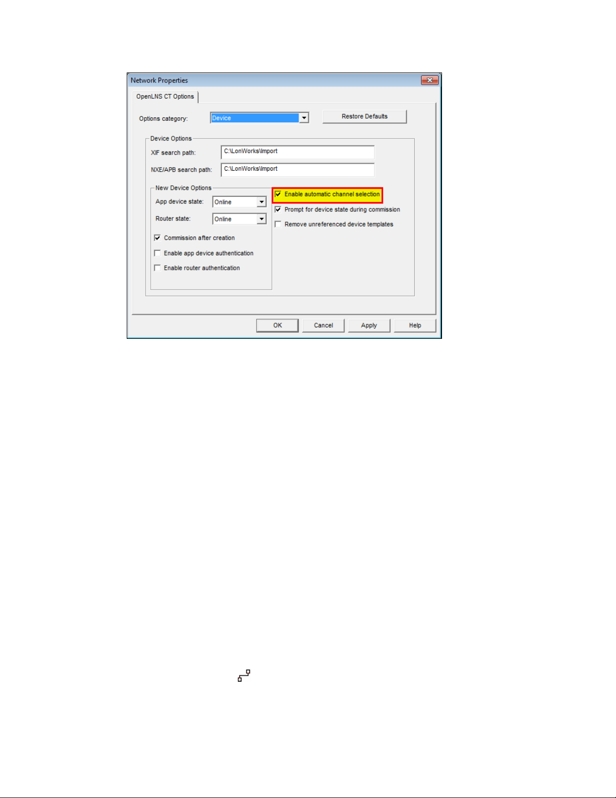
You can also have automatic channel selection enabled by default in each OpenLNS CT drawing you
create or open. In the OpenLNS CT Design Manager, click the OpenLNS CT Default Options tab,
select Device from the Options Category list, and then select the Enable Automatic Channel
Selection check box.
The order of the criteria used by OpenLNS CT to select the appropriate channel is as follows: (1)
closest qualified channel to the device SmartShape, in which the channel SmartShape is within 1 ½
times the width of the device SmartShape; (2) most recently used or created channel; and (3) other
available defined channels. If no channel can be selected using the preceding criteria, the New Device
Wizard will appear.
Automatic channel selection only applies to those device SmartShapes that include a device template
definition and channel type information such as master device SmartShapes and copies of existing
device SmartShapes. The New Device Wizard will therefore always appear when you drag the generic
Device SmartShape from the OpenLNS CT Basic Shapes stencil to your OpenLNS CT drawing.
Changing the Channel of an Application Device
You can move an application device to a different channel, preserving the device’s configuration and
all of its connections. You can do this to assign a device to a channel different than the one that was
automatically selected by OpenLNS CT, or to physically move a device to a different compatible
channel. To move a device to a different channel, you can either right-click the device and then click
Move Device on the shortcut menu, or you can use the Connector tool on the Visio Standard toolbar
to graphically move the device.
To use the Move Device command, right-click the device SmartShape and click Move Device on the
shortcut menu. See Moving OpenLNS CT SmartShapes in this chapter for how to move a device using
the Move Device command.
To use the Visio Connector tool to move the device, follow these steps:
1. Select the Connector tool (
2. Position the Connector tool over the “x” connection point of the device so that a red box opens
over the “x”.
80 Designing Networks
) on the Visio Standard toolbar.
Page 97

3. Click and hold the mouse button.
4. Drag the Connector tool to the center of the SmartShape of the desired channel so that a red box
opens around the channel SmartShape.
5. Release the mouse button.
6. Select a different tool on the Visio toolbar if you will not be making additional connections or
reassignments (if you continue to use the Connector tool to add new devices, routers, or
functional blocks SmartShapes to your drawing, Visio will attempt to connect the SmartShapes,
which may not be desired or could generate errors.)
Creating Functional Blocks
A functional block encapsulates a set of network variables and configuration properties that perform a
specific device function. For example, a four-port digital input device could have functional blocks for
each of its four digital inputs. Each functional block would contain an output network variable
representing the state or setting of a digital input. In addition, each functional block could contain
configuration properties that control how frequently the digital input data is transmitted to other
functional blocks. Ultimately, the task that the functional block performs in this example is
transmitting the digital input data to other functional blocks (another functional block recei vi ng the
digital input data could then use it to turn a lamp on or off).
You can create a functional block in one step. To do this, you enable automatic d e vice selection and
then drag a custom functional block master SmartShape to your OpenLNS CT drawing near the device
to which you want to assign the functional block. Otherwise, the New Functional Block Wizard opens
when you add a functional block SmartShape to your OpenLNS CT drawing. See Using Automatic
Device Selection in this section for how to enable this feature. See Chapter 12, Creating and Using
OpenLNS CT SmartShapes and Stencil, for how to create and use custom functional block master
SmartShapes.
To add a functional block to an OpenLNS CT drawing, follow these steps:
1. Drag a Functional Block SmartShape (
OpenLNS CT drawing. The Functional Block Wizard opens unless you enabled automatic device
selection and dropped a custom functional block master SmartShape near a device SmartShape.
) from the OpenLNS CT Basic Shapes stencil to your
OpenLNS CT User’s Guide 81
Page 98

2. Enter the following information:
Source Functional
Block
Name Displays the name of the source functional block (a master
SmartShape or an existing functional block) from which the new
functional block was created.
This box will be empty if the functional block was created by
dragging the generic functional block master SmartShape to the
OpenLNS CT drawing.
Type Displays the functional profile represented by the source functional
block (open loop sensor object, for example).
This box will be empty if the functional block was created by
dragging the generic functional block master SmartShape to the
OpenLNS CT drawing.
Subsystem
Name Specify the subsystem containing the functional block’s device.
The default is the subsystem containing the functional block.
Browse Click to browse the subsystem hierarchy and assign the functional
block to a device in a different subsystem.
Device
Name Select a device from a list of all the devices in the selected
subsystem that supports the functional block you are creating. If
you are creating a generic functional block SmartShape, all devices
82 Designing Networks
Page 99

in the selected subsystem with available functional blocks will be
listed.
Type Specifies the device template associated with the functional block.
Functional Block
Select whether the functional block you are creating is static or
dynamic.
• Static/Existing. Select a functional block that is defined in the
device interface.
• Dynamic FB. This option is only available fo r devi ces that
support dynamic functional blocks (for example, a controller
such as the SmartServer).
Type / FPT File
If you selected Static/Existing, select the functional profile for the
functional block. The default is the functional profile for the
functional block currently listed in the Functional Block Name
box.
If you selected Dynamic FB, select the functional profile type file
from the FPT File list.
Instance / FPT Type If you selected Static/Existing, select which instance of the
functional profile in the Type box to be created.
If you selected Dynamic FB, select the standard functional profile
template (SFPT) or user-defined functional profile template
(UFPT) to be assigned to the dynamic functional block.
Name Select the functional block.
If you are creating a functional block from a custom SmartShape
that specifies a specific functional profile, the number of functional
blocks listed corresponds with the number of available functional
blocks matching the functional profile on the associated device.
For example, if you create a functional block for a 4-port digital
input device that has four digital inputs, four digital input
functional blocks (one for each input) will initially be listed. If
you then create a second functional block for the same device, only
three functional blocks will be available in the list.
If you are creating a generic functional block SmartShape, all
possible functional blocks for the selected device will initially be
listed.
ID Displays the scope and functional profile number of the functional
block using the form <Scope>:<Number>.
If the functional block is a LonMark standard functional profile
then the “<Scope>:” is omitted because it is 0.
New FB Name Enter the name of the functional block. This name must be unique
within the device and should be descriptive of the task to be
performed by the functional block. The name may be up to 85
characters, but it may not include the period, backslash, colon,
forward slash, or double quote characters.
If the functional block was created from a master SmartShape or a
copy of an existing functional block, t he defa ul t funct i o nal b l ock
name is the name of the source functional block. If there is a
naming conflict, a separator character and an instance number
(starting at 1) are appended to the functional block name. For each
OpenLNS CT User’s Guide 83
Page 100

subsequent functional block with the same name for the same
device, the instance number is incremented by one.
For example, the default name of a new functional block created
from a digital output functional block master SmartShape named
“LED” would be “LED” if it was the only one named as such for
the assigned device. If a copy of the LED functional block was
created and assigned to the same device, the default name would
be “LED 1”. A second copy would be named “LED 2”, and so on.
If a functional block is created by dragging the generic functional
block master SmartShape to the OpenLNS CT drawing, the default
functional block name is the programmatic name of the functional
block.
OpenLNS CT by default inserts the name of the associated device
and a period before the functional block name in the OpenLNS CT
drawing. Therefore, if the first digital output functional block
named “LED” in the previous example was created for a device
named “DO- 1”, the default functional bloc k name would actually
be “DO- 1.LED”. The second functional block named “LED”
assigned to that same device would be “DO- 1.LED- 1”, and so on.
To enable or disable this feature for all new OpenLNS CT network
designs or for an existing OpenLNS CT network design, set or
clear the Include Device Name in Default FB Name check box in
the Network Properties: Functional Block options category as
described in Appendix A.
To change the default naming convention for all new OpenLNS
CT network designs or for an existing OpenLNS CT network, set
options in the Network Properties: Naming options category as
described in Appendix A.
Number of FBs
Create
Create all Network
Variables Shapes
Dynamic FBs
Create all Mandatory
NVs
Create all Optional
NVs
Enter the number of functional blocks to be created. When more
than one functional block is created, the additional functional
blocks will retain the same name as the first, and will be assigned
to other devices in the same subsystem. For example, if the first
functional block is assigned to Device 1, the second will be
assigned to Device 2. If a matching device does not exist, you will
be prompted to select the device.
Select this check box to automatically create SmartShapes for all
network variables defined in the functional block.
You can add unassigned network variables after the functional
block has been created if this check box is cleared.
Select this check box to automatically create all mandatory
network variables defined in the functional profile for a dynamic
functional block. The network variables are created in the
OpenLNS network database.
To create the SmartShapes in your OpenLNS CT drawing, select
the Create all Network Variables Shapes check box.
Select this check box to automatically create all optional network
variables defined the functional profile for a dynamic functional
block. The network variables are created in the OpenLNS network
database.
To create the SmartShapes in your OpenLNS CT drawing, select
84 Designing Networks
 Loading...