

Page 1
NodeBuilder
User’s Guide Release 4
®
Resource Editor
®
0 7 8 - 0 1 9 4 - 0 1 C
Page 2

Echelon, LON, LonWorks, Neuron, 3120, 3150, Digital
Home, i.LON, LNS, LonMaker, LonMark, LonPoint, LonTalk,
NodeBuilder, ShortStack, and the Echelon logo are
trademarks of Echelon Corporation registered in the
United States and other countries. FTXL, LonScanner,
LonSupport, OpenLDV, and LNS Powered by Echelon
are trademarks of Echelon Corporation.
Other brand and product names are trademarks or
registered trademarks of their respective holders.
Neuron
Chips and other OEM Products were not
designed for use in equipment or systems which involve
danger to human health or safety or a risk of property
damage and Echelon assumes no responsibility or
liability for use of the Neuron
Chips or LonPoint Modules
in such applications.
Parts manufactured by vendors other than Echelon and
referenced in this document have been described for
illustrative purposes only, and may not have been tested
by Echelon. It is the responsibility of the customer to
determine the suitability of these parts for each
application.
ECHELON MAKES NO REPRESENTATION, WARRANTY, OR
CONDITION OF ANY KIND, EXPRESS, IMPLIED, STATUTORY,
OR OTHERWISE OR IN ANY COMMUNICATION WITH YOU,
INCLUDING, BUT NOT LIMITED TO, ANY IMPLIED
WARRANTIES OF MERCHANTABILITY, SATISFACTORY
QUALITY, FITNESS FOR ANY PARTICULAR PURPOSE,
NONINFRINGEMENT, AND THEIR EQUIVALENTS.
No part of this publication may be reproduced, stored in
a retrieval system, or transmitted, in any form or by any
means, electronic, mechanical, photocopying,
recording, or otherwise, without the prior written
permission of Echelon Corporation.
Printed in the United States of America.
Copyright ©1997–2009 by Echelon
Corporation.
Echelon Corporation
www.echelon.com
ii
Page 3

Table of Contents
Preface ..................................................................................................... v
Purpose .......................................................................................................... vi
Audience......................................................................................................... vi
Content........................................................................................................... vi
Related Manuals............................................................................................. vi
For More Information and Technical Support.................................................vii
1 Introduction to Resource Files ........................................................ 1
Introduction to Resource Files......................................................................... 2
2 Getting Started .................................................................................. 5
Installing the Resource Editor..........................................................................6
Starting the Resource Editor ...........................................................................7
Setting Resource Editor Options.....................................................................7
3 Using Resource Folders................................................................... 9
Introduction to Resource Folders ..................................................................10
Browsing the Resource Catalog....................................................................10
Adding a Resource Folder.............................................................................12
Removing a Resource Folder........................................................................12
Moving a Resource Folder ............................................................................12
Refreshing the Resource Catalog .................................................................13
Searching for a Resource..............................................................................13
4 Creating and Modifying a Resource File Set ................................ 15
Creating and Modifying a Resource File Set.................................................16
Using the Standard Program ID Calculator ............................................20
Viewing Resource File Properties .................................................................24
5 Creating and Modifying Resources............................................... 25
Introduction to Creating and Modifying Resources .......................................26
Creating and Modifying a Network Variable or Configuration Property
Type...............................................................................................................26
Using the LonMaker Browser to Calculate Raw Values.........................31
Creating and Modifying a Structure or Union NV or CP Type ................32
Creating and Modifying an Enumerated NV or CP Type........................33
Creating and Modifying a Bitfield............................................................33
Creating and Modifying a Reference NV or CP Type.............................34
Creating and Modifying a Functional Profile..................................................35
Adding a Network Variable Member to a Functional Profile...................38
Adding a Configuration Property Member to a Functional Profile ..........41
Using Cascading Resource File Sets .....................................................44
Creating and Modifying an Enumeration Type .......................................45
Creating and Modifying a Language String...................................................48
Adding a String to a Language File.........................................................48
Adding a String While Defining a Resource............................................49
Searching for a Language String............................................................50
Creating, Modifying, and Translating a Language File...........................53
Creating and Modifying a Resource Format..................................................55
Using The Text Format Specifier............................................................58
Using Conversion Specifications......................................................60
Using a Conditional Format..............................................................61
NodeBuilder Resource Editor User's Guide iii
Page 4

Using a Scaling Factor and Unit String ............................................61
Using Localized List Separators.......................................................62
Using Localized Time and Date Formats.........................................62
Copying Resources.......................................................................................63
Removing and Obsoleting Resources...........................................................64
Purging a Resource File Set...................................................................64
Converting a Resource File Set.....................................................................65
6 Generating Resource Files............................................................. 69
Generating Resource Files............................................................................70
Resource Reports..........................................................................................71
Appendix A: Language File Extensions............................................. 73
Appendix B: NodeBuilder Resource Editor Software License
Agreement ............................................................................................. 75
iv Preface
Page 5

Preface
This document describes LONMARK resource files and how to use the
NodeBuilder Resource Editor to view, create, and modify them.
.
NodeBuilder Resource Editor User's Guide v
Page 6

Purpose
This document describes resource files and how to use the NodeBuilder Resource Editor
to view, create, and modify them.
Audience
This document is intended for device manufacturers who are creating resource files for
their L
resource definitions.
ONWORKS
®
devices, and is also intended for network integrators who need to view
Content
This guide includes the following content:
• Chapter 1,
It describes the types of resources contained within resource files and how they are
used by network tools.
• Chapter 2,
Resource Editor.
• Chapter 3,
all available resource folders on your computer, and how to add, move, and remove
resource folders.
• Chapter 4,
modify a resource file set.
• Chapter 5,
and how to modify existing resources.
• Chapter 6,
you have made changes using the resource editor.
Introduction to Resource Files, presents an introduction to resource files.
Getting Started, describes how to install and start the NodeBuilder
Using Resource Folders, describes how to use the resource catalog to view
Creating and Modifying a Resource File Set, describes how to create or
Creating and Modifying Resources, describes how to define new resources
Generating Resource Files, describes how to generate resource files once
• Appendix A,
files.
• Appendix B,
software license that you must agree to.
Language File Extensions, lists the file extensions used for language
NodeBuilder Resource Editor Software License Agreement, contains the
Related Manuals
The documentation related to the NodeBuilder Resource Editor is provided as Adobe®
PDF files and online help files. The PDF files are installed in the Echelon
NodeBuilder program folder when you install the NodeBuilder tool. You can download
the latest NodeBuilder documentation, including the latest version of this guide, from
Echelon’s website at
The following manuals provide supplemental information to the material in this guide.
You can download these documents from Echelon’s Web site at
®
LonMaker
vi Preface
User’s Guide
www.echelon.com/support/documentation/manuals.
www.echelon.com.
Describes how to use the LonMaker Integration Tool to
design, commission, modify, and maintain L
networks.
ONWORKS
Page 7
LONMARK® SNVT and SCPT
Guide
Documents the standard network variable types
(SNVTs), standard configuration property types
(SCPTs), and standard enumeration types that you can
declare in your applications.
Neuron
®
C Reference Guide
Provides reference information for writing programs
using the Neuron C language.
Neuron® C Programmer’s Guide
Describes how to write programs using the Neuron
Version 2.2 language.
ShortStack User's Guide Release
2.1
Describes how to develop an application for a
LONWORKS device using Echelon’s ShortStack 2.1 Micro
Server. It describes the architecture of a ShortStack
device and how to develop a ShortStack device.
For More Information and Technical Support
The NodeBuilder Resource Editor ReadMe file provides descriptions of known
problems, if any, and their workarounds. To view the NodeBuilder ReadMe, click
Start, point to Programs, point to NodeBuilder, and then select NodeBuilder
Resource Editor ReadMe First.
If you have technical questions that are not answered by this document, the NodeBuilder
Resource Editor online help, or the NodeBuilder Resource Editor ReadMe file, you can
contact technical support. To receive technical support from Echelon, you must purchase
support services from Echelon or an Echelon support partner. See
www.echelon.com/support for more information on Echelon support and training
services.
®
C
You can also enroll in training classes at Echelon or an Echelon training center to learn
more about developing devices. You can find additional information about device
development training at
www.echelon.com/training/courses/default.htm.
You can obtain technical support via phone, fax, or e-mail from your closest Echelon
support center. The contact information is as follows:
Region
The Americas
Languages Supported Contact Information
English
Japanese
Echelon Corporation
Attn. Customer Support
550 Meridian Avenue
San Jose, CA 95126
Phone (toll-free):
1-800-258-4LON (258-4566)
Phone: +1-408-938-5200
Fax: +1-408-790-3801
lonsupport@echelon.com
NodeBuilder Resource Editor User's Guide vii
Page 8

Region Languages Supported Contact Information
Europe
English
German
French
Italian
Echelon Europe Ltd.
Suite 12
Building 6
Croxley Green Business
Park
Hatters Lane
Watford
Hertfordshire WD18 8YH
United Kingdom
Phone: +44 (0)1923 430200
Fax: +44 (0)1923 430300
lonsupport@echelon.co.uk
Japan
China
Other Regions
Japanese Echelon Japan
Holland Hills Mori Tower,
18F
5-11-2 Toranomon, Minatoku
Tokyo 105-0001
Japan
Phone: +81-3-5733-3320
Fax: +81-3-5733-3321
lonsupport@echelon.co.jp
Chinese
English
Echelon Greater China
Rm. 1007-1008, IBM Tower
Pacific Century Place
2A Gong Ti Bei Lu
Chaoyang District
Beijing 100027, China
Phone: +86-10-6539-3750
Fax: +86-10-6539-3754
lonsupport@echelon.com.cn
English Phone: +1-408-938-5200
Fax: +1-408-328-3801
lonsupport@echelon.com
You can submit a feedback form with suggestions on how to improve the product’s
functionality and documentation at
form is not forwarded to technical support and should not be used to submit
product support related issues
www.echelon.com/company/feedback. This feedback
technical or
. Please send technical support questions to your Echelon
support center.
viii Preface
Page 9

Introduction to Resource Files
This chapter presents an introduction to resource files. It describes the
types of resources contained within resource files and how they are used
by network tools.
1
NodeBuilder Resource Editor User's Guide 1
Page 10

Introduction to Resource Files
Resource files provide definitions of functional profiles, type definitions, enumerations,
and formats that can be used by network tools such as the LonMaker tool. The type
definitions include definitions for network variable types and configuration property
types.
Resource files are grouped into resource file sets, where each set applies to a specified
range of program IDs. The program ID range is determined by a program ID template in
the file, and a scope value for the resource file set that specifies the fields of the program
ID template that are used when matching the program ID template to the program ID of
a device. The program ID template has an identical structure to the program ID of a
device, except that the applicable fields may be restricted by the scope. The scope value
can be seen as a filter, indicating the relevant parts of the program ID. The scope may be
one of the following:
0 – Standard
3 – Manufacturer
4 – Manufacturer and Device Class
5 – Manufacturer, Device Class, and Device Subclass
6 – Manufacturer, Device Class, Device Subclass, and Device Model
For a device to use a resource file set, the program ID of the device must match the
program ID template of the resource file set to the degree specified by the scope. This
allows each L
ONWORKS manufacturer to create resource files that are unique to their
devices.
For example, consider a resource file set with a program ID template of
81:23:45:01:02:05:04:00 and manufacturer and device class scope (scope 4). Any
device with the manufacturer ID fields of the program ID set to 1:23:45 and the device
class ID fields set to 01:02 would be able to use types defined in this resource file set,
whereas resources on devices of the same class but by a different manufacturer could not
access this resource file set.
A resource file set may also reference information in any resource file set with a
numerically lower scope provided the relevant fields of their program ID templates
match. For example, a scope 4 resource file set can reference resources in a scope 3
resource file set, provided the manufacturer ID components of the resource file sets’
program ID templates match.
Scopes 0 through 2 are reserved for standard resource definitions published by Echelon
and distributed by the L
ONMARK association. Scope 0 applies to all devices, and scopes 1
and 2 are reserved for future use. Since scope 0 applies to all devices, there is a single
scope 0 resource file set called the standard resource file set. A standard resource file set
is included with the NodeBuilder tool, but periodic updates are available from the
ONMARK association at www.lonmark.org. You can define your own functional profiles,
L
types, and formats in scope 3 through 6 resource files.
Each resource file set may contain definitions for the following resources:
Network Variable Types Type information for network variables. This
information includes the size, units, scaling
factors, and type category (float, integer, signed,
etc) for each type. Network variables can
2 Introduction to Resource Files
Page 11

contain a single value or they can contain a
structure or union containing multiple fields (for
example, the SNVT_date_cal network variable
contains 3 fields for the year, month, and day).
Network variables can also contain enumerated
values which allow the network variable to be
set to one of a discrete number of values.
Network variables types are defined in a
resource file with a “.typ” extension.
Configuration Property
Types
Type information for configuration properties.
This information includes the size, units, scaling
factors, and type category (float, integer, signed,
etc) for each type. Like network variables,
configuration properties can contain structures,
unions, and enumerated values. Configuration
property types are defined in a resource file with
a “.typ” extension (this is the same file used for
network variable types).
Functional Profiles Functional profiles define a template for
functional blocks. A functional block is a
collection of network variables and configuration
properties designed to perform a single function
on a device. Each functional profile can define
mandatory and optional configuration properties
and network variables. When a functional block
implements a functional profile, it must
implement all mandatory network variables and
configuration properties defined by the
functional profile, and it may implement some,
all, or none of the optional network variables
and configuration properties. Functional
profiles are defined in a resource file with an
“.fpt” extension. Functional profiles are also
called functional profile templates.
Enumeration Types An enumeration type is a list of numerical
values, each associated with a mnemonic name.
If a network variable or configuration property
type contains an enumeration, the definitions of
the enumerated values are maintained
separately as an enumeration type.
Enumeration types are defined in a resource file
with a “.typ” extension (along with network
variable and configuration property types), and
may also be defined in a separate C header file
(“.h” extension).
Language Strings Network variable types, configuration property
types, functional profiles, and enumeration types
can all reference text information used to
describe their name, units, and function. This
text information is contained in separate
language files. There is one language file for
NodeBuilder Resource Editor User's Guide 3
Page 12

every language your resource file set supports.
When a language file is translated, the
references contained in the network variable
types, configuration property types, and
functional profiles still point to the appropriate
strings. The file extension of each language file
depends on the language. The standard
language extensions are listed in Appendix A,
Language File Extensions.
Formats Each network variable and configuration
property type must have at least one format
defined. This format describes how the value
will be displayed to or entered by network
integrators and network operators. It is possible
to define multiple formats for a network variable
type or configuration property type. Different
formats can provide the information in a
different order (if the value is a structure or
union) or provide a different scaling factor (for
example, the SNVT_temp_f network variable
type has three formats, one for Fahrenheit, one
for differential Fahrenheit, and one for Celsius).
Formats are defined in format files with an
“.fmt” extension.
4 Introduction to Resource Files
Page 13

Getting Started
This chapter describes how to install and start the NodeBuilder Resource
Editor.
2
NodeBuilder Resource Editor User's Guide 5
Page 14

Installing the Resource Editor
The NodeBuilder Resource Editor is available as a standalone application, and is also
available as part of certain tools such as Echelon's NodeBuilder Development Tool. This
chapter describes how to install the standalone resource editor. See the documentation
for your application to install a NodeBuilder Resource Editor as part of that application.
To install the standalone resource editor, follow these steps:
1. Download the ResEdit.exe file to your computer. The file is available from the
Members area of the L
2. Click the Windows Start menu, click Run, and then open ResEdit.exe. The
NodeBuilder Resource Editor Setup application appears.
3. Enter a temporary folder to unpack the Setup application into, and then click
Continue. If this is a new folder, a confirmation window appears. Click Yes to
create the folder. The Setup application files are unpacked and the Welcome window
appears.
4. If a window appears that states than an older version of Windows Installer was
found, click OK to continue.
5. Click Next. The License Agreement window appears.
ONMARK Web site.
6. Read through the license. If you agree with the terms of the license, click I Accept
the Terms of the License Agreement, and then click Next. The Customer
Information window appears. If you do not agree with the terms of the license
agreement, click Cancel and do not install the software.
7. Enter the following information. Much of this information is automatically entered
into resource files that you will create with the resource editor, so it will save you
time later if you enter complete information now.
User Name Your name.
Organization The company you work for.
Phone Number A phone number where a contact can be reached.
Email Address An email address where a contact can be reached.
Web Address Your company's Web site.
LonMark Manufacturer
ID
Installation Option Click
8. Click Next. The Destination Folder window appears.
If your company has a L
ID, enter it here. If you do not have a
manufacturer ID, get a free temporary
manufacturer ID from
Anyone Who Uses this Computer to
make the resource editor available to all users on
this computer.
ONMARK manufacturer
www.lonmark.org/mid.
9. Select a destination folder for the NodeBuilder Resource Editor, and then click Next.
The Setup Type window appears.
10. Select Complete, and then click Next. The Ready to Install window appears.
11. Click Install. The installation completes.
6 Getting Started
Page 15
Starting the Resource Editor
You can use the NodeBuilder Resource Editor to create, modify, and view resource files,
and also to add user resource files to the resource catalog. To start the NodeBuilder
Resource Editor, click the Windows Start button, point to Programs > Echelon
NodeBuilder >, and then click NodeBuilder Resource Editor. The NodeBuilder
Resource Editor window appears.
Setting Resource Editor Options
You can set resource editor options that control how resources are displayed and specify
the active language file. To view and modify resource editor options, follow these steps:
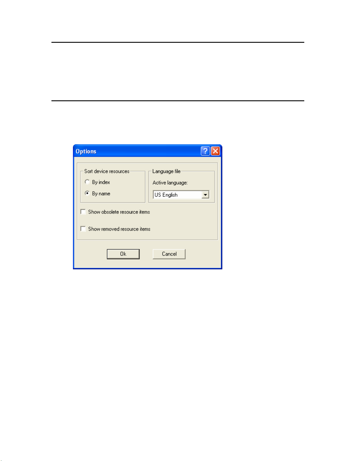
1. Click View, and then click Options. The Options dialog opens:
2. Enter the following information:
Sort Device Resources Displays resource items sorted by name or by
index. If
sorted alphabetically. If
they are sorted by resource file index.
Active Language Determines the language file that new strings will
be placed in. This is called the active language
file. See
String
Show Obsolete Resource
Items
Show Removed Resource
Items
3. Click OK.
NodeBuilder Resource Editor User's Guide 7
Display resource items that have been marked
obsolete. See
Display resource items that have been removed.
See
By Name is selected, resource items are
By Index is selected,
Creating and Modifying a Language
.
Removing and Obsoleting Resources.
Removing and Obsoleting Resources.
Page 16

8 Getting Started
Page 17

Using Resource Folders
This chapter describes how to use the resource catalog to view all
available resource folders on your computer, and how to add, move, and
remove resource folders.
3
NodeBuilder Resource Editor User's Guide 9
Page 18
Introduction to Resource Folders
A resource folder is a directory containing one or more resource file sets. You will
typically create your resource file sets in a resource folder with your company name that
is contained in the L
you may create a resource folder in C:\LonWorks\Types\User\MyCo. If you anticipate
creating many resource file sets, you may organize them in resource folders contained
within your company resource folder.
A resource catalog is a file containing a list of resource folders. The resource catalog file
is a file with a .cat extension. By default, the resource catalog file is contained in your
ONWORKS Types folder and is named ldrf.cat (the full path is
L
C:\LonWorks\Types\ldrf.cat by default. Network tools use the resource catalog to find
all the resources that are defined on your computer. The resource editor also uses the
resource catalog to display all of your available resources.
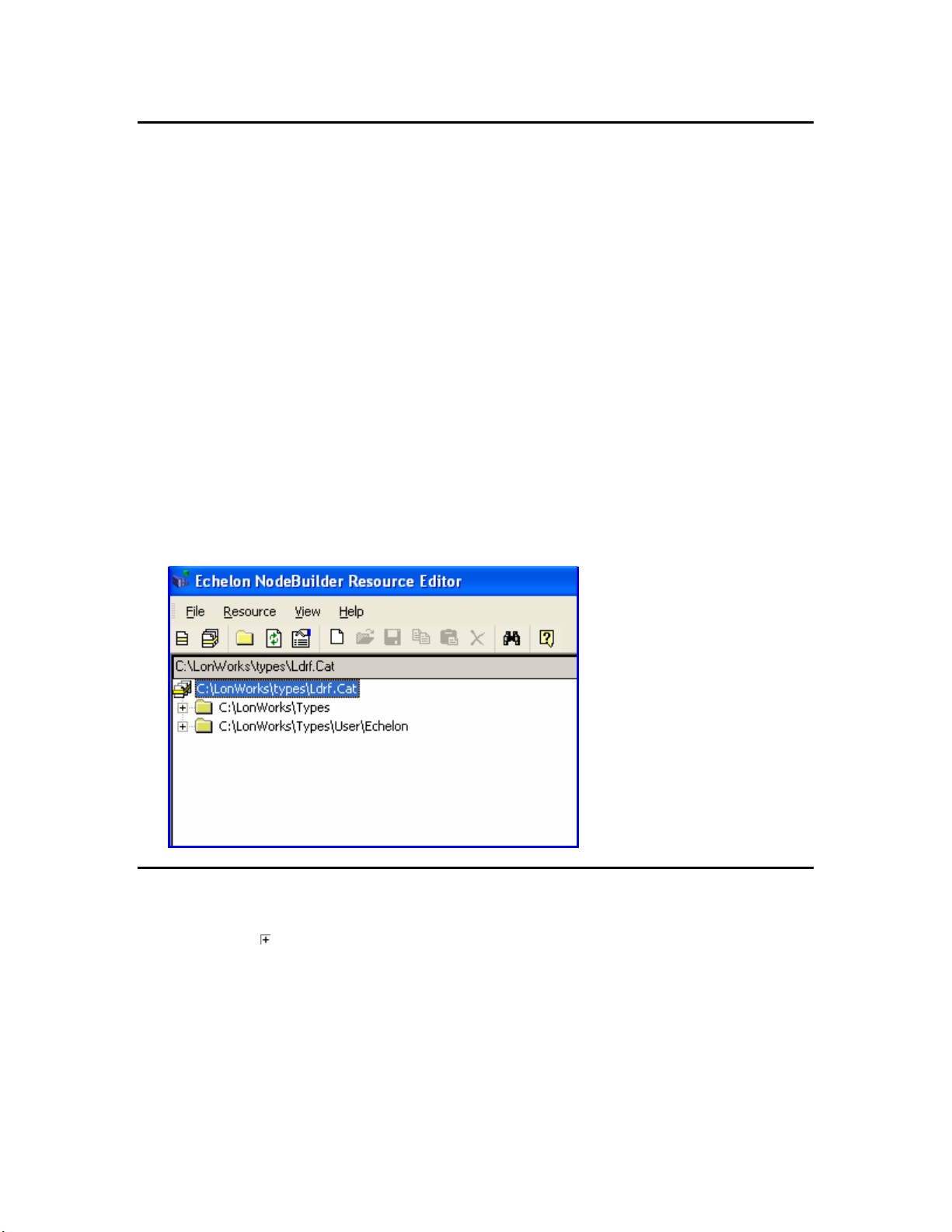
The resource editor displays a hierarchical view of your resource catalog, and all the
resource folders and resource files that it contains. The resource catalog is the top of the
hierarchy. The second level of the hierarchy below the resource catalog file contains
entries for each of the resource folders contained in the resource catalog. In the following
figure, the resource catalog file is C:\LonWorks\type\Ldrf.Cat and it contains two
resource folders: C:\LonWorks\Types and C:\LonWorks\Types\User\Echelon. The
C:\LonWorks\Types folder contains the standard resource file set, and the
C:\LonWorks\Types\User\Echelon folder contains Echelon-specific resource file sets.
ONWORKS Types\User folder. For example, if you work for MyCo,
Browsing the Resource Catalog
You can browse the resource catalog to view all the resource definitions contained within
it. Click the
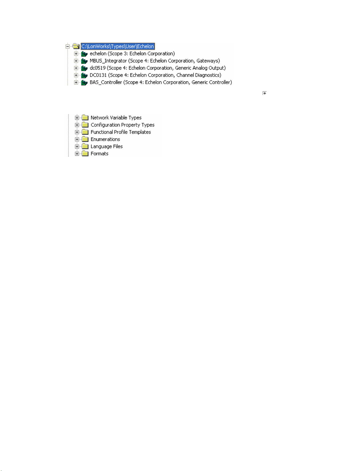
When you expand a resource folder you will see all resource file sets contained in that
folder. Each folder can hold multiple resource file sets. Each resource file set in the
folder is listed with its name and its scope. For example, the Echelon user resource
folder may appear as shown in the following figure:
10 Using Resource Folders
icon next to a resource folder to expand the hierarchy beneath it.
Page 19
To view or modify the contents of a resource file set, expand it using the
button. When
you expand a resource file set you will see six folders containing resource file
components, as shown in the following figure:
Each resource file set contains all of these folders, but some of them may be empty:
Expand these folders to view or modify the following resources:
Network Variable Types Contains the network variable types defined by
this resource file set. Network variable types
are used to implement network variables. They
can also be referenced by other network variable
or configuration property types, and may be
referenced by functional profile templates.
Configuration Property
Types
Contains the configuration property types
defined by this resource file set. Configuration
property types are used to implement
configuration properties. These types will
typically be referenced by one or more functional
profile templates.
Functional Profile Templates
Contains the functional profiles defined by this
resource file set.
Enumerations Contains the enumeration types defined by this
resource file set. Network variable and
configuration property types can use these
enumeration types.
Language Files Contains the language files defined by this
resource file set. Each language file contains a
set of strings translated into a specific language.
Expand a language file to browse the individual
strings in the language file.
Language string resources are used to provide
language-dependent details for all of the above
resources.
Formats Contains the formats defined by this resource
file set. Each network variable type and
configuration property type must have at least
one format.
NodeBuilder Resource Editor User's Guide 11
Page 20

Adding a Resource Folder
You can add a new resource folder to the resource catalog. This makes all resource file
sets contained within the folder available to network tools running on your computer,
and also allows you to view and modify the resource files contained within the folder
using the resource editor. To add a resource folder, follow these steps:
1. Right-click the resource catalog file at the top of the resource catalog, and then click
Add Folder on the shortcut menu. You can also click the Add Folder (
the toolbar, or open the File menu and then click Add Folder. An Add Folder
window appears.
2. Browse to the folder to be added to the resource catalog, and then click OK. The
folder should be located in a Types\User\<Manufacturer Name> folder within
your L
by default). The resource folder appears in the resource catalog.
ONWORKS folder (this is C:\LonWorks\Types\User\<Manufacturer Name>
) button on
Removing a Resource Folder
You can remove a resource folder from the resource catalog. Removing a resource folder
deregisters that folder from the resource catalog; it does not delete the resource files
within the folder. Use Windows Explorer to delete the files if you want to delete the
resource folder and its content.
To remove a resource folder, right-click the resource folder to be removed in the resource
catalog, and then click Remove on the shortcut menu. The resource folder name is
removed from the resource catalog.
Be careful not to remove resource folders that contain resource file sets that are
referenced by your remaining resource file sets, as this could render other resources
invalid.
Moving a Resource Folder
You can move a resource folder to a different directory. To move a resource folder, follow
these steps:
1. Use Windows Explorer to create the new folder.
2. Use Windows Explorer to move the resource file set to the new folder. A resource file
set consists of a type file (“.typ” extension), functional profile file (“.fpt” extension),
format file (“.fmt” extension), and one or more language files with an extension
dependent on the language (“.enu” for English US strings). A resource file set may
become unusable if one or more of these files are missing, so copy all of these files
together if you copy or move the resource file set to another directory or computer.
3. Remove the old resource folder from the resource catalog as described in
Resource Folder
4. Add the new resource folder to the resource catalog as described in Adding a
Resource Folder
12 Using Resource Folders
.
.
Removing a
Page 21
Refreshing the Resource Catalog
The resource catalog may get out of sync with the resource files on your computer if you
update resource files using a tool other than the resource editor, if you delete a resource
file set using Windows Explorer, if you update the resource file API on your computer, or
if you copy new resource files into a resource folder using Windows Explorer. If this
occurs, refresh the resource catalog in the resource editor by right-clicking the resource
catalog file at the top of the resource catalog and then clicking Refresh Catalog on the
shortcut menu. Any empty resource folders are removed when you refresh the resource
catalog.
Any folders that are not present in your file system will automatically be removed from
the resource catalog. This means that if you add a resource folder that is in a network or
removable drive, and that folder becomes inaccessible, you will have to add the folder to
the resource catalog again once the folder becomes available.
Searching for a Resource
You can search for specific resources in the resource catalog. You can search for network
variable types, configuration property types, functional profiles, enumerations, language
strings, or formats. You can search an individual resource file, a resource file set, a
resource folder, or the entire resource catalog. To search for a resource, follow these
steps:
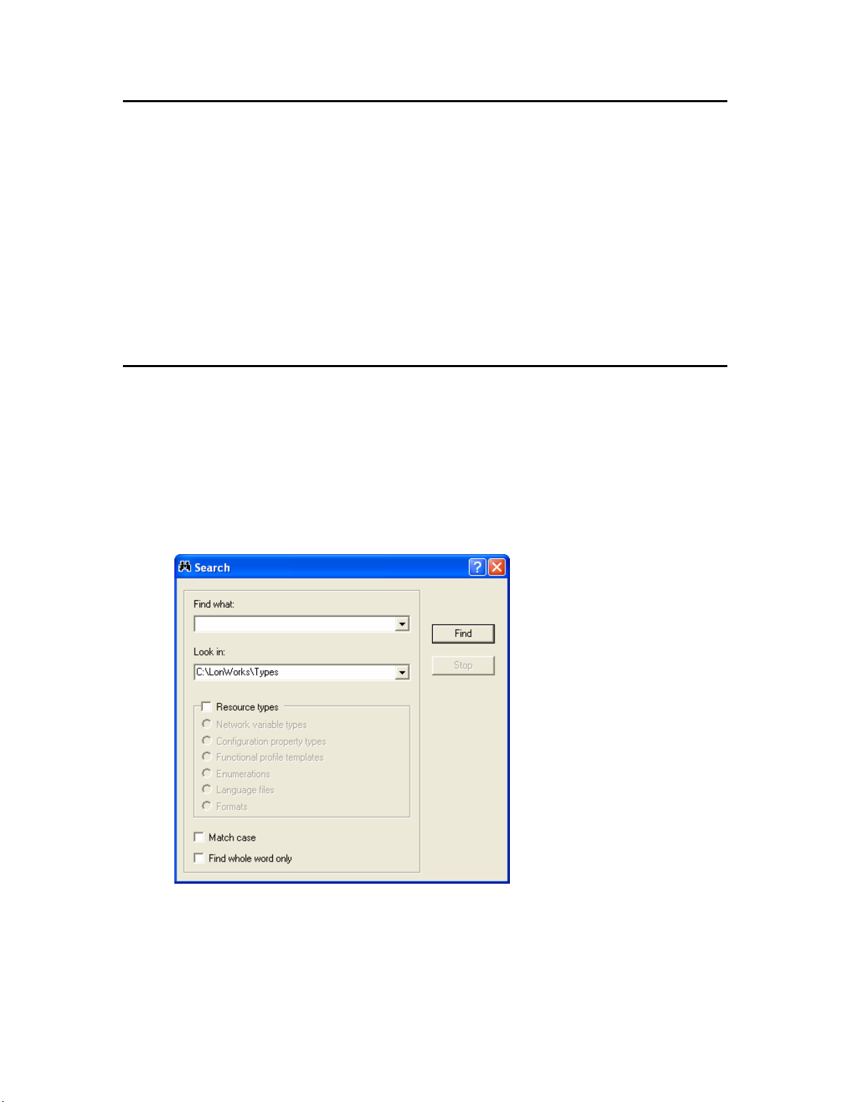
1. Right-click the folder to search in the resource catalog and then click Search on the
shortcut menu. The search will cover all resources within the folder that you select.
The Search dialog opens:
2. Enter the parameters for the search entering the following information:
Find What The string to search for. You can enter all or part
of a variable type name, configuration property
type name, functional profile name, enumeration
type name, language string, or format name. For
NodeBuilder Resource Editor User's Guide 13
Page 22

example, you can enter “switch” to search for
SNVT_switch.
Look In The resource catalog, resource folder, resource file
set, or resource file to search. By default, this will
contain the folder you selected to begin the search.
Click the arrow to increase the scope of the
search. A list of your original selection and all
levels of the resource catalog above your selection
appears.
Resource Types The type of resource to search for. You can limit
the search to
Network Variable Types,
Configuration Property Types, Functional
Profile Templates
Strings
, or Formats. Clear Resource Types to
, Enumerations, Resource
search all resource types.
Match Case Searches for strings with the same case that you
enter in
Find What.
Find Whole Word Only Searches for strings where the whole string
matches what you enter in
Find What. The
search will not return results that contain the
string in the
Find What field if it is part of a
larger word.
3. Click Find. The first search result appears in the resource catalog. Close the Search
window to operate on the result, or click Find Next to search for more results. To
stop a search in progress, click Stop.
14 Using Resource Folders
Page 23

4
Creating and Modifying a Resource File
Set
This chapter describes how to create or modify a resource file set.
NodeBuilder Resource Editor User's Guide 15
Page 24

Creating and Modifying a Resource File Set
You can create a new scope 3, 4, 5, or 6 resource file set within any resource folder. Each
resource file set has a number of properties that you will set when you create the set.
You can edit these properties at any time.
The number of resource file sets that you will create will depend on the number of device
types that you expect your company to develop, and the level of coordination that exists
between your developers. For all but the largest enterprises, you may find it easiest to
create a single manufacturer scope (scope selector 3) resource file set for your company,
and use it to maintain and distribute all of your company’s user types. Larger
enterprises may find it easier to coordinate manufacturer and device class scope (scope
selector 4) resource file sets, where a unique resource file set is created for each class of
devices. Very large enterprises can request multiple manufacturer IDs from the
ONMARK association, assign a different manufacturer ID to each major division that
L
ONWORKS development, and then maintain a separate scope selector 3 resource file
does L
set for each division. If your company has multiple L
it useful to initially create manufacturer, device class, and device subclass scope (scope
selector 5) resource file sets during development, and then copy the definitions to the
appropriate scope selector 3 or 4 resource file set when complete. You can create a
manufacturer, device class, device subclass, and device model scope (scope selector 6)
resource file set for any special-purpose types that you want to apply to a single device
type.
ONWORKS developers, you may find
To create a new resource file set or edit an existing one, follow these steps:
1. Add a resource folder for your company if you do not have one already as described in
Adding a Resource Folder.
2. To create a new resource file set, right-click the resource folder, and then click New
Resource File Set on the shortcut menu. To modify the properties for an existing
resource file set, right-click the resource file set, and then click Open on the shortcut
menu. The Modify Resource File Set dialog opens with the General tab selected:
16 Creating and Modifying a Resource File Set
Page 25
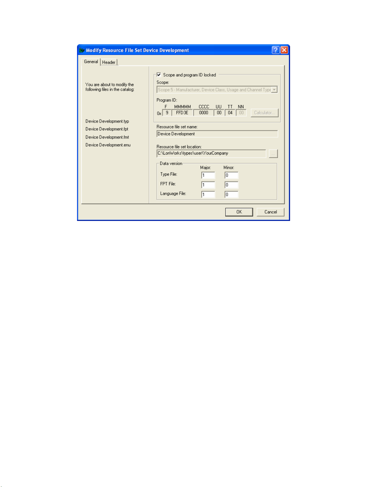
3. Enter the following information about the resource file set:
Scope/Program ID
Locked
Prevents modification of the scope or program ID
template for this resource file set. This option is
not displayed when you are creating a new
resource file set because the scope and program
ID template can be freely changed when you are
creating a resource file set. This option appears
when you are modifying a resource file set because
modifying these options in an existing resource
file set can break resources that reference this
resource file set. You can modify the
Program ID for an existing resource file set my
clearing
Scope/Program ID Locked. Be sure to
fix any references to the resource file set if you do
this
Scope The scope for the resource file set. See
Introduction to Resource Files for more
information.
Program ID
The program ID template for the resource file set.
Click Calculator to open the Standard Program
ID Calculator (see Using the Standard Program
ID Calculator). You only need to specify the
program ID template fields that are required for
the selected scope. Set all other fields to 0. If you
use the standard program ID calculator, verify
that these fields are set to 0 after closing the
calculator. The Standard Development
Scope and
NodeBuilder Resource Editor User's Guide 17
Page 26
Program ID setting is always ignored for
resource files and should be cleared. The required
values for each scope are as follows:
• Scope 3: Manufacturer.
• Scope 4: Manufacturer and Device class.
• Scope 5: Manufacturer, Device Class,
Usage, Channel Type, Has Changeable
Interface, and Usage Field Values Defined
by Functional Profile.
• Scope 6: Manufacturer, Device class,
Usage, Channel Type, Has Changeable
Interface, Usage Field Values Defined by
Functional Profile, and Model Number.
To change the program ID of an existing resource
file set, create a new resource file set with the
desired program ID and copy the resources from
the old resource file set to the new one.
If you attempt to add or create a resource file set
with a duplicate scope and program ID template
to an existing resource file set, a warning is
displayed when you generate the resource file set.
You can resolve the conflict by removing one of
the conflicting sets, or by changing the scope and
program ID template of one of the sets.
Resource File Set Name The name of the resource file set as it will appear
in the resource catalog. To change the name of an
existing resource file set, you must copy it and
remove the old resource file set, or edit the
resource file names using Windows Explorer and
restart the Resource Editor.
Resource File Set
Location
The resource folder containing the resource file
set. Depending on which method you used to
create the resource file set, you may be able to
change the resource folder. If enabled, click
to create or select a new folder. If you select a
folder that is not in the resource catalog, it will
automatically be added. You cannot change the
location for an existing resource file set. To
change the location of an existing resource file set,
copy it to the new location, then remove the old
resource file set.
Data Version The version number of the resource files. By
default,
Major is set to 1 and Minor is set to 0 for
a new resource file set (i.e. version 1.0). Increment
the major or minor version number whenever you
publish new resource files (see Generating Resource
Files Using the Resource Editor).
18 Creating and Modifying a Resource File Set
Page 27
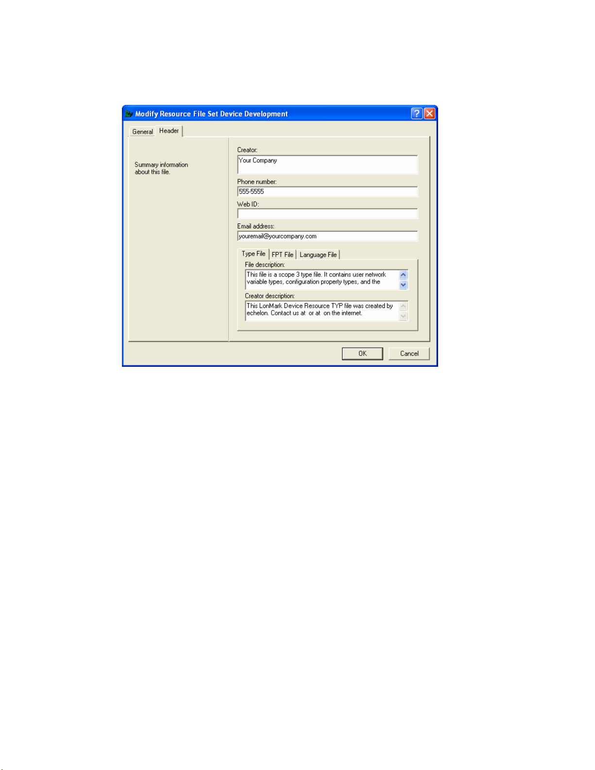
4. Click the File Header tab.
5. Enter the following company information for the resource file set:
Creator
The name of the company, and optionally the
person, to contact about this resource file set.
Phone Number The phone number to contact for questions about
this resource file set.
Web ID The Web address of the company that created this
resource file set.
Email Address The email address to write to for more
information about this resource file set. Enter a
valid email address for general inquiries, such as
lonworks@echelon.com, or the specific email
address of the resource file set creator (e.g.
joe.block@acme.com).
File Description Text descriptions for the type file, functional
profile, or language file (depending on what tab is
selected). The default value is a string specifying
the scope and file type.
Creator Description Optional additional creator information (company
name, contact information, etc) for the type file,
functional profile, or string file (depending on
what tab is selected). The default value is a string
containing the information from the NodeBuilder
Registration Properties tab. Changing the
Creator, Phone Number, Web ID, and Email
NodeBuilder Resource Editor User's Guide 19
Page 28

address fields in this tab will not update this
string.
6. Click OK. If you are creating a new resource file set, it is created and added to the
resource catalog. If you are updating a resource file set, any changes are written to
the resource file set. You can now add new network variable types, configuration
property types, functional profiles, enumeration types, language strings, and formats
to the resource file set. See
The Resource Editor can open older resource file formats. If you open a resource file set
of an older resource file format version, the version will automatically be updated to the
latest available format when you generate the resource files as described in Chapter 6,
Generating Resource Files. To convert a resource file set to an older version, see
Converting a Resource File, later in this chapter.
Creating and Modifying Resources for more information.
Using the Standard Program ID Calculator
The program ID is a 16-hex-digit number that uniquely identifies the device interface for
a device. You can format the program ID as a standard or non-standard program ID.
When formatted as a standard program ID, The 16 hex digits are organized as 6 fields
that identify the manufacturer, classification, usage, channel type, and model number of
the device. The Standard Program ID Calculator makes it easy for you to select the
appropriate values for these fields by allowing you to select from lists contained in a
program ID definition file included with the NodeBuilder tool and updated by the
ONMARK Interoperability Association.
L
To start the Standard Program ID Calculator from the NodeBuilder Device Template
Wizard (see Creating a NodeBuilder Project from the LonMaker Tool in the NodeBuilder
User’s Guide), click Calculator in the Program ID window. To start the Standard
Program ID Calculator from the New Resource File Set dialog (see Creating a New
Resource File Set or Editing an Existing Set), click Calculator in the dialog. The
Standard Program ID Calculator appears as shown in the following figure:
20 Creating and Modifying a Resource File Set
Page 29

This dialog allows you to choose a value for each part of the standard program ID. The
Program ID field at the bottom of the dialog displays the current program ID. Enter
the following values to set the program ID:
Manufacturer The device manufacturer. Click the arrow to
select from a list of all the L
manufacturers who are members of the L
ONWORKS device
ONMARK
Interoperability Association. If your company is a
member of the L
ONMARK association but is not
included in the list, download the latest program
ID data from
company is not a member of the L
www.lonmark.org/spid. If your
ONMARK
association, get a temporary manufacturer ID
www.lonmark.org/mid. If your company is a
from
ONMARK member, but not listed in the updated
L
program ID list, or if you have a temporary
manufacturer ID, select
[Decimal]>
in the Manufacturer list, then enter
<Enter Number
your manufacturer ID in the field to the right of
the Manufacturer field. Enter the value in
decimal, the calculator converts it to hex for the
program ID. You do not have to join the
ONMARK association to get a temporary
L
manufacturer ID, the information required to get
one is very minimal, and there is no fee to get one.
However, if your company is not a member of the
ONMARK Interoperability Association, now is a
L
good time to join. For more information, see
www.lonmark.org.
Category The general purpose or industry of the device.
Click the arrow to select from a list of categories
maintained by the L
ONMARK association. The
Category determines the device classes that will
be available in
Device Class. Select ALL to have
Device Class show all existing device classes.
Select
Profiles By Name to have Device Class
show an alphabetical list of all device classes with
a profile on the L
ONMARK website. Select
Profiles By Number to have Device Class show
a numerical list (sorted by device class number) of
all device classes with a profile on the L
ONMARK
Web site.
Device Class
The primary function of the device. The primary
function of the device is determined by the
primary functional profile implemented by your
device. Your device must implement at least one
functional profile, and may implement multiple
functional profiles. If you implement multiple
functional profiles, determine which is the
primary based on the most typical usage of your
device. Enter one of the following depending on
your primary functional profile:
NodeBuilder Resource Editor User's Guide 21
Page 30

• If you are using a standard functional profile
other than functional profiles 0 through 6 and
the functional profile is included in the
standard resource file set, click the arrow and
select the functional profile name. The device
class will be set to the functional profile
number for the selected functional profile.
• If you are using a standard functional profile
other than functional profiles 0 through 7 that
has not yet been included in the standard
resource file set, click the arrow and select
<Enter Number [Decimal]>, and then enter
the functional profile number in the two boxes
to the right of Device Class. Enter the last
two decimal digits in the second box, and the
remaining decimal digits in the first box.
• If your primary functional profile is based on
standard functional profiles 1 through 7 (you
cannot use functional profiles 0 or 6 as the
primary functional profile) or a user functional
profile, click the arrow to select from a list of
device classes maintained by the L
ONMARK
association. You can update the list by
downloading the latest program ID data from
www.lonmark.org/spid. To enter a device
class value that has not yet been added to the
standard list, select <Enter
Number[Decimal]> and enter a decimal
value from 0 to 255 in each of the fields to the
right of the Device Class field (the calculator
converts the values to hex for the program ID).
Usage The intended usage of the device. The most
significant two bits are determined by the
Changeable Interface
Defined By Functional Profile
below the
usage value, set
Profile
Usage box. If you are using a standard
Defined By Functional
, and then click the arrow to select from a
and Use Field Values
checkboxes
Has
list of standard usage values maintained by the
ONMARK association. You can update the list by
L
downloading the latest program ID data from
www.lonmark.org/spid. If the primary functional
profile implemented by your device specifies
custom usage values, clear
Defined By Functional Profile
Number[Decimal]>
Usage Field Values
, select <Enter
in the Usage list, and then
enter a decimal value from 0–255 in the field next
to the Usage list (the calculator translates the
value to hex for the program ID).
Channel Type The channel type supported by the device’s
ONWORKS transceiver. Click the arrow to select
L
22 Creating and Modifying a Resource File Set
Page 31

from a list of channel types maintained by the
ONMARK association. You can update the list by
L
downloading the latest program ID data from
www.lonmark.org/spid. Select Custom if you are
using a transceiver that is not compatible with
any of channel types in the list. To enter a
channel type value that has not yet been added to
the standard list, select
Number[Decimal]>
<Enter
and enter a decimal value
from 0 to 255 in the box to the right of the
Channel Type box (the calculator converts the
value to hex for the program ID).
Model Number The specific product model. Assign a unique
model number for the specified manufacturer,
device class, usage, and channel type. You may
use the same hardware for multiple model
numbers depending on the program that is loaded
into the hardware. The model number within the
program ID does not have to conform to your
published model number. This value can be
automatically updated by setting
Program ID Management
Automatic
in the Program ID
window of the device template wizard (described
earlier in this chapter). Enter a model number
within the range specified in the device template
wizard.
Standard Development
Program ID
Has Changeable Interface
Identifies this device as a development or
prototype device. Set this checkbox if the device
has not been certified by the L
ONMARK
Interoperability Association. When set, the
calculator sets the
When cleared, the calculator sets the
F field of the program ID to 9.
F field of the
program ID to 8—this value is reserved for devices
certified by the L
ONMARK association.
Set this checkbox to indicate that the device has a
changeable device interface. Set this checkbox if
the device has any network variables with
changeable types, or if the device supports
dynamic network variables.
Dynamic network variables are network variables
that are added at installation time by a network
tool. You can only implement dynamic network
variables on host-based devices, so you cannot use
them in any Neuron Chip or Smart Transceiverhosted devices that you develop with the
NodeBuilder tool.
Network variables with changeable types are
network variables whose type can be modified at
installation time by a network tool. You can
implement changeable type network variables on
NodeBuilder Resource Editor User's Guide 23
Page 32

any type of device. See the Using the Resource
Editor chapter in this document and the Neuron C
Programmer’s Guide for more information.
Usage Fields Defined By
Functional Profile
Program ID This box is automatically updated when you
Set this checkbox if the primary functional profile
implemented by this device defines usage values.
Otherwise, clear the checkbox to specify standard
usage values. When set, the
set to <Enter Number>. Enter the custom usage
value in the box to the right of the
change the other boxes. You can also enter some
or all of the program ID components directly into
this box. If you enter values directly, the
calculator updates the other boxes to match what
you have entered.
Usage value will be
Usage box.
Viewing Resource File Properties
You can see a summary of many of the items in the resource catalog by right-clicking
them and then clicking Properties on the shortcut menu. A window appears showing
information about the resource that was selected. You can view the following properties:
Catalog Right-click the resource catalog file at the top of
the resource catalog, and then click
Properties
window showing the number of directories,
number of type files, number of functional profile
files, number of format files, and number of
language files contained in the resource catalog.
on the shortcut menu to display a
Catalog
Resource File Set Right-click a resource file set and then click
Properties on the shortcut menu to display a
window showing the header information for the
resource file set, as well as the header information
for each type file, functional profile file, format
file, and language file contained in the resource
file set.
Network Variable Types,
Configuration Property
Types, Functional Profile
Templates, Enumerations,
Language Files, and Format
Files
Right-click a resource file folder and then click
Properties on the shortcut menu to display a
window showing the header of the resource file set
and the header or headers of the files that contain
the definitions displayed in the selected folder.
24 Creating and Modifying a Resource File Set
Page 33

Creating and Modifying Resources
This chapter describes how to define new resources and how to modify
existing resources.
5
NodeBuilder Resource Editor User's Guide 25
Page 34

Introduction to Creating and Modifying Resources
You can create and modify any resources within a scope 3, 4, 5, or 6 resource file set,
though you cannot do this for resource file sets not created by your company. If you are
modifying a resource file set that you have previously released, you must be careful to
make changes that are backward-compatible with your released products. You can add a
resource at any time and not affect your existing products. You can also add new
enumeration values to enumeration types without affecting your existing products. The
following sections describe how to create and modify resources.
Creating and Modifying a Network Variable or Configuration Property Type
You can create and edit network variable types and configuration property types in any
scope 3, 4, 5, or 6 resource file set. Do not attempt to do this in resource file sets that do
not have your manufacturer ID or that you do not manage. If you create a configuration
property types in a scope 6 resource file set, then create a configuration property in a
device based on that type, a network integrator will be unable to preserve the value of
the configuration property when the device is upgraded, since a new configuration
property type (with a new program ID template) will have to be created, and the tool
doing the upgrading will identify it as being a new configuration—and therefore
incompatible—property.
To add a network variable type or configuration property type to a resource file set or to
modify an existing network variable type or configuration property type, follow these
steps:
1. To create a new type in a resource file set, right-click the Network Variable Types
or Configuration Property Types folder in the resource file set and then click
New NVT or New CPT on the shortcut menu. To modify an existing type, doubleclick the type. The New/Edit Network Variable Type or New/Edit
Configuration Property Type dialog opens:
26 Creating and Modifying Resources
Page 35

The figure above shows the New or Existing Configuration Property Type dialog.
The New Network Variable Type dialog is identical except it does not contain Type
Range Override and Default Value or Inherited from a Network Variable.
2. Enter a name for the new network variable type or configuration property type in NV
Name or CP Name. Network variable type names must start with the letters
“UNVT.” Configuration property type names must start with the letters “UCPT.” By
default the name of the network variable or configuration property type is UNVT<NV
Index> or UCPT<CP Index>, respectively. The network variable or configuration
property index is shown in the status bar at the bottom of the window. Every new
network variable and configuration property in a resource file set will be assigned a
unique index (i.e. if you create a network variable with an index of 1 and then
remove it, the next network variable you create will still have an index of 2. See
Removing and Obsoleting Resources for more information).
By convention, user network variable type (UNVT) names have an underscore after
“UNVT”; the first letter after the underscore is lower case; and the name uses all
lower case with words separated by underscores (i.e. UNVT_scale_data). By
convention, user configuration property type (UCPT) names do not have an
underscore after the “UCPT” prefix, the first letter after UCPT is lower case, and the
name uses mixed case (i.e. UCPTadcFilter). Network variable type names are
limited to 64 characters, including the “UNVT_” and “UCPT” prefixes. You can use
upper and lower case alphanumeric characters and underscores. You cannot use
spaces or other special characters in names.
NodeBuilder Resource Editor User's Guide 27
Page 36

3. Select the network variable or configuration property data type in Data Type.
If you are defining a configuration property type, and the type depends on the type of
a network variable that the configuration property type applies to, set Inherited
From a Network Variable. You can use this to create a configuration property
type that will be used in multiple functional profiles that require different types. If
this checkbox is set, the data type will be set to INHERITED and cannot be changed
and Type Range and Default Value will be dimmed. When you implement a
configuration property that uses an inherited configuration property type, the
network variable the configuration property inherits from depends on how you
implement the configuration property. If you associate the configuration property
with a network variable, it will inherit its type from the network variable. If you
associate the configuration property with a functional block, it will inherit its type
from the principal network variable on that functional block. Configuration
properties that inherit their type from a changeable type network variable will
automatically change type when the network variable’s type is changed. See the
Neuron C Programmer’s Guide for details about changeable type network variables.
Configuration properties that inherit their type from a network variable cannot apply
to the entire device.
You can create an array type if you are defining fields of a structure or union. To
create a network variable or configuration property type array, first construct a
structure, create a field within the structure, set Array, and then specify the size of
the array in Dimension. See
CP Type
.
Creating and Modifying a Structure or Union NV or
Also see
Adding a Configuration Property Member to a Functional Profile, later in
this chapter, for details about creating arrays of configuration properties as
functional profile members.
If the type is not inherited, click the arrow to select from the following data types:
BITFIELD A signed or unsigned bitfield, 1-8 bits wide. Only
available for fields within a structure or union.
Creating and Modifying a Bitfield.
See
DOUBLE FLOAT A standard IEEE 754 64-bit floating point value.
ENUMERATED A signed 8-bit enumerated value. See Creating
and Modifying an Enumerated NV or CP Type
.
FLOAT An IEEE 754 standard 32 bit floating point value.
REFERENCE A reference to a network variable type. Uses the
type definition of the referenced network variable
type. If you are creating a structure or union, an
individual field can reference a network variable
type (see
Union NV or CP Type
Creating and Modifying a Structure or
). If the referenced network
variable type changes in some way, the
referencing type or field will automatically change
as well. See
NV or CP Type
Creating and Modifying a Reference
for more information.
SIGNED_CHAR An 8-bit signed character value.
SIGNED_LONG A 16-bit signed integer value.
28 Creating and Modifying Resources
Page 37

SIGNED_QUAD A 32-bit signed integer value.
SIGNED_SHORT An 8-bit signed integer value.
STRUCTURE A structure containing multiple fields. See
Creating and Modifying a Structure or Union NV
or CP Type
.
UNION A union containing multiple fields. See
Creating
and Modifying a Structure or Union NV or CP
.
Type
UNSIGNED_CHAR An 8-bit unsigned character.
UNSIGNED_LONG A 16-bit unsigned integer value.
UNSIGNED_QUAD A 32-bit unsigned integer value.
UNSIGNED_SHORT An 8-bit unsigned integer value.
4. If you are modifying an existing type, Make this Item Obsolete appears beneath
Data Type. Set this checkbox to make this type obsolete as described in
and Obsoleting Resources
.
Removing
5. If you are creating a configuration property type, set the values in Type Range
Override and Default Value (if you are creating a network variable type, skip to
step 6). Set the default value, as well as override minimum and maximum values. If
this is a reference configuration property, these limits will override the minimum and
maximum values set in the Limits tab of the referenced network variable type.
Use Type Range Override and Default Value to select Minimum, Maximum,
Invalid, or Default. Enter a hexadecimal value for each of these. You can only
enter raw hexadecimal data, so when setting the default value for a structure, union,
or floating point type, you must know the hexadecimal representation of the
structure, union, or floating point type. See Using the LonMaker Browser to
Calculate a Raw Value for information on using the LonMaker browser to determine
the hexadecimal representation of complex types.
You can inspect the formatted version of the data entered into Type Range
Override and Default Value in Formatted Value. If you have changed the type
definition, this value may be based on outdated formatting rules; to ensure that the
latest rules are applied, click OK to save changes and re-open the configuration
property type by right-clicking it and clicking Open on the shortcut menu.
6. Click the Strings tab. This following tab appears:
NodeBuilder Resource Editor User's Guide 29
Page 38

7. Enter or link to text to provide a language-dependent name for the type, a language-
dependent comment about the type, and a language-dependent name of the units for
the type (for example, “Celsius” or “Kilometers-per-Hour”). If you enter a new string,
it is created as a new language string in the currently active language file (see
Setting Resource Editor Options). You can later translate this string to other
languages as described in
Creating, Modifying, and Translating a Language File.
8. Click the Limits tab. This following tab appears:
9. For scalar types or scalar members of aggregates, set minimum and maximum
allowable values for the type in the Min and Max fields, and the value to which the
network variable or configuration property will be set when its value is unknown in
the Invalid field. By default, Min and Max will contain the largest and smallest
possible values for the Data Type in the Attributes tab (see Step 3). You can set the
limits for each field of a structure or union. You must create a format for the type for
these limits to appear correctly in network tools such as the LonMaker tool. See
Creating and Editing a Resource File Format for more information.
You can click Reset to set the associated Min or Max field to the limit supported by
the data type set in the Attributes tab. For example, if the type is set to Signed
Short, clicking the reset buttons will display a Min value of –128 and a Max value of
127.
10. Click the Scales tab. The following tab appears:
30 Creating and Modifying Resources
Page 39

11. Set scaling factors for this type. This allows types to represent values outside of the
limits of the base type. For example, an UNSIGNED_SHORT data type can contain
raw values between 0 and 255. By changing the scale, it could be used to represent
values from 50-305, or from 0 to 510 (but contain only even values). The formula for
converting the raw value to the scaled value is shown on the tab. By default, Scale
A is 1, and Scale B and Scale C are 0, resulting in identical values for the raw value
and scaled value (i.e. Scaled Value = 1 * 10
your scaling factors by entering a value into Raw Value Example and observing the
scaled value that appears in Scaling Result. You must create a format for the type
for these limits to appear correctly in network tools such as the LonMaker tool. See
Creating and Modifying a Resource Format for more information.
0
* (Unscaled Value + 0)). You can test
12. Click OK. The new network variable or configuration property type is added to the
Network Variable Types or Configuration Property Types folder. A default
format is created for the network variable or configuration property type as described
Creating and Modifying a Resource Format.
in
Using the LonMaker Browser to Calculate Raw Values
You can use the LonMaker Browser in the LonMaker tool to simplify setting default,
invalid, minimum override, and maximum override configuration property values in the
resource editor (see Step 5 in
Configuration Property Type
values that you must enter. This value can be difficult to determine without the
LonMaker Browser for configuration property types that use structure, union, or floating
point types. To determine the raw hexadecimal value of a value, follow these steps:
1. Create the configuration property type using the resource editor as described in
Creating and Modifying a Network Variable or Configuration Property Type.
2. Create a device that uses the configuration property type.
3. Add the device to a LonMaker network drawing.
4. Right-click the device, and then click Browse on the shortcut menu. The LonMaker
Browser appears.
5. Find the configuration property you created. Right-click the configuration property,
and then click Details on the shortcut menu. The LonMaker Browser’s Details
dialog opens.
Creating and Modifying a Network Variable or
). The LonMaker Browser calculates the raw hexadecimal
NodeBuilder Resource Editor User's Guide 31
Page 40

6. Set the individual values of the fields in the structure, union, or the floating-point
value to the desired default or override value and then click OK to return to the
browser.
7. Right-click the configuration property, and then click Change Format on the
shortcut menu. The LonMaker Browser’s Change Format dialog appears.
8. Select Built-in Data Types from Format Files, then select Raw (Hex) from
Formats Available, and then click OK to return to the browser. If the device you
are browsing is not commissioned, you will get a warning message, which you can
ignore.
9. The value is displayed as a comma separated list of values in the Browser window.
Each value is a two-byte hexadecimal number (the browser removes leading zeroes).
10. Return to the configuration property type in the resource editor and enter the
hexadecimal value for the default or override. Prefix a zero to any single digit values
in the comma-separated list. For example, if the LonMaker Browser shows a value of
“0,5,b,36,c,3,db,” enter “00050b360c03db.”
Creating and Modifying a Structure or Union NV or CP Type
You can create network variable and configuration property types with multiple fields,
each with their own data type, by defining a type as a structure or union. The fields in a
structure are separate, whereas the fields in a union may overlap. For example, if a
structure type contained an UNSIGNED_SHORT and an UNSIGNED_LONG field, the
total size is 24 bits (8 bits for the short, and 16 bits for the long). If a union type
contained these same two fields, the total size is 16 bits; the short shares the first 8 bits
of the long. Unions and structures can both contain any data types, including other
unions and structures, with the exception of bitfields, which can be used in structures,
but not unions.
Note: While the display of the structure type bears a resemblance to Neuron C code, it is
not in Neuron C syntax, and cannot be cut and pasted directly into a Neuron C file. To
implement a variable using a network variable or configuration property type in Neuron
C version 2 or later, simply declare this variable using the type name defined in the
resource file. For example, SNVT_count MyCount; defines a variable, not a network
variable, of type SNVT_count.
To create a union or structure type, follow these steps:
1. Create a new type as described in
Configuration Property Type
2. Set Data Type to UNION or STRUCTURE. The left pane displays typedef
struct { } or typedef union { }.
3. Right-click the typedef struct or typedef union statement, and then click
Insert Field on the shortcut menu. Enter attributes, strings, limits, and scales for
the new field as described in
Configuration Property Type
in the Neuron C language, but is otherwise not limited (i.e. it does not have to start
with “UNVT” or “UCPT” for fields). Each field contains its own data type, strings,
limits, and scales. Repeat this step for each field in the structure.
4. Click OK. The new type appears in the Network Variable Types or
Configuration Property Types folder.
To make changes to a field, click the field in the left pane and modify the field definition.
Creating and Modifying a Network Variable or
.
Creating and Modifying a Network Variable or
). Name must be a valid name for an aggregate member
32 Creating and Modifying Resources
Page 41

To remove a field, right-click the field in the left pane, and then click Remove Field on
the shortcut menu.
Creating and Modifying an Enumerated NV or CP Type
You can assign an enumerated type to a network variable type, configuration property
type, or a field in a structure or union. To create an enumerated type, follow these steps:
1. If the enumeration type you will use does not already exist, create it as described in
Creating and Modifying an Enumeration Type.
2. Create a new type as described in Creating and Modifying a Network Variable or
Configuration Property Type
Information appears in the dialog as shown in the following figure:
. In step 3, set Data Type to enumeration. Enum
3. Set Enum Scope to the scope of the resource file set containing the enumeration
type. You can select an enumeration type from the resource file set containing the
type you are creating, or from any resource file set with a numerically lower scope
and matching program ID template. File Path is automatically updated to the path
of the resource file set with the appropriate scope and program ID type. Enum Set
is updated to contain all enumerations available in that resource file set.
4. Select the enumeration type to use in Enum Set. Minimum and Maximum display
the minimum and maximum values for the selected enumeration type. You can use
these values to further restrict the range of available values for this type.
5. Continue creating the network variable or configuration property type as described in
Creating and Modifying a Network Variable or Configuration Property Type.
Creating and Modifying a Bitfield
You can define a field of a structure as a bitfield. This data type is defined as a Neuron C
bitfield. A bitfield is packed into a byte that can have from 1 to 8 bitfields that can each
be 1 to 8 bits, for a total of no more than 8 bits per byte (for example, you can have one 8bit field, two 4-bit fields, or 8 1-bit fields in a byte, or various combinations of these).
Two subsequent bitfields whose total size exceeds the 8 bit boundary automatically cause
a gap of unused data between the fields. To create a bitfield, follow these steps:
1. Create a new structure or union type as described in
Structure or Union NV or CP Type
bitfield.
. Set Data Type to ENUMERATED for the
Creating and Modifying a
2. Enter the following information:
NodeBuilder Resource Editor User's Guide 33
Page 42

Size The size of the bitfield, in bits, from 1 to 8. The
bitfield size determines the maximum value the
field can contain. An unsigned bitfield of W bits
W
width can accept values 0..2
of width W can hold values -2
-1, a signed bitfield
W/2
W/2
..+2
-1
Offset The offset of the bitfield within the byte. A full
byte is always required regardless of how many
bits in the bitfield are used. This value
determines where in the byte the values will be
set. This value can be from 0 to (8 – Size).
Signed/Unsigned Specifies a signed or unsigned value. An unsigned
bitfield can only contain positive values. A signed
bitfield can contain positive or negative values
with negative numbers values stored using twos
complement notation. Twos complement notation
is created by converting the number to binary,
complementing each bit, and adding 1 to the
resultant binary number.
A signed bitfield with a width of 1 can contain
only two values: -1 (minus one) and 0 (zero). This
is often unwanted; the developer is likely to
require an unsigned bitfield of the same width,
accepting 0 (zero) and +1 (plus one). The use of
unsigned bitfields is recommended due to a
slightly better performance on the Neuron Chip,
but also in order to avoid the common mistake of
declaring bitfields with a width of one bit as
signed.
Unlike the ANSI-C and Neuron C programming languages, resource files do not support
anonymous bitfields (bitfields that are declared with signedness and width, but without a
name, e.g. int : 3;) or bitfields with a width of 0. To control the positioning of a
bitfield within the compound byte, set the offset value accordingly. If the Resource
Editor detects a gap between bitfields, it will display a warning describing the situation
and offer to leave the gap intact, or to close the gap by adjusting the offset preferences
accordingly. Do not allow automatic adjustment if you have purposefully laid out the
bitfields to match some specific requirement.
Creating and Modifying a Reference NV or CP Type
Network variable types, configuration property types, and fields within structure or
union types can be based on existing network variable types (but not configuration
property types) that are defined within the same resource file, within the standard
resource file, or within any other resource file that has a compatible program ID
template and scope selector. When this is done, if the referenced type changes in some
way (type size, fields, etc), any configuration property and network variable types that
reference it will automatically be changed as well. To create a type based on an existing
type, follow these steps:
1. Create a new type as described in
Configuration Property Type
Information appears in the dialog as shown in the following figure:
Creating and Modifying a Network Variable or
. In step 3, set Data Type to reference. Reference
34 Creating and Modifying Resources
Page 43

2. Set Type Scope to the scope of the resource file set containing the referenced
network variable type. You can select a network variable type from the resource file
set containing the network variable or configuration type you are creating, or from
any resource file set with a numerically lower scope and matching program ID
template. File Path is automatically updated to the path of the resource file set
with the appropriate scope and program ID template, and NV Name is updated to
contain all network variable types available in that resource file set.
3. Set NV Name to the network variable type to use. Type Index and Type Size are
automatically updated when you set this value. Type Index indicates the index of
the network variable type within its resource file set. Type Size indicates the
number of bytes in the selected network variable type.
4. Continue creating the network variable or configuration property type as described in
Creating and Modifying a Network Variable or Configuration Property Type.
Creating and Modifying a Functional Profile
You can create and edit a functional profile in any scope 3, 4, 5, or 6 resource file set.
You can define a functional profile that inherits members from a scope 0 profile, or you
can create a new functional profile. When you inherit from a scope 0 profile, you can add
your own members to the scope 0 profile, or you can override members in the scope 0
profile.
Do not attempt to create or modify functional profiles in resource file sets that do not
have your manufacturer ID or that you do not manage. Functional profiles are used to
create functional blocks. Each functional profile can contain mandatory and optional
network variables and configuration properties. To create or modify a functional profile
in a resource file set, follow these steps:
1. To create a new functional profile, right-click the Functional Profile Templates
folder in the resource file set and then click New FPT on the shortcut menu. A new
functional profile template will be added to the resource file set. To modify an
existing functional profile, skip to step 3.
2. If this is a new functional profile, enter the name. The name must start with “UFPT”
and may not contain spaces. By convention, there is no underscore following UFPT;
the first letter after UFPT is lower case; and the name uses mixed case. Functional
profile names are limited to 64 characters, including the “UFPT” prefix. You can use
upper and lower case alphanumeric characters and underscores. You cannot use
spaces or other special characters in names; a functional profile name must meet the
requirements of a Neuron C variable name with the additional restriction that the
NodeBuilder Resource Editor User's Guide 35
Page 44

dollar character is not permitted in a functional profile name. By convention, the
functional profile name should indicate the application set of the profile, e.g.
“SFPToccupancySensor”, or “UFPTturboCharger”.
3. Double-click the functional profile. The Modify Functional Profile dialog appears.
This dialog contains three panes: a Available Types pane showing all resources that
may be referenced by this functional profile; a Functional Profile pane that displays
the network variables and configuration properties defined as part of this functional
profile; and a Member Details pane that displays functional profile properties or
properties of member network variables and configuration properties.
4. Enter the following information about this functional profile in the Member Details
pane:
Inherit Members from
Scope 0
Specifies that this functional profile inherits
network variable and configuration property
members from the scope 0 profile with the same
key. You can use this option to add new members
to an existing standard functional profile, to
redefine existing members of an existing standard
functional profile, or both.
Enter the functional profile number in
FPT Key.
This value must be set to a value less than 20000
to inherit from a scope 0 profile. When the
Inherit Members from Scope 0 checkbox is set,
all network variables and configuration properties
36 Creating and Modifying Resources
Page 45

from the selected standard profile will be
referenced by the functional profile (if there is no
standard functional profile template with the
same profile number, setting this option will have
no effect). All inherited members will be
displayed in pink, while new ones will be shown in
light blue.
You cannot remove any of the inherited network
variables and configuration properties, but you
can override them, or add additional network
variables and configuration properties. To
override an inherited network variable or
configuration property, add a new configuration
property or network variable with the same
direction and name. The capitalization of the
name must match. When you close the pane (e.g.
by clicking
OK), you will be prompted to confirm
the override. Overridden network variables and
configuration properties will inherit string
information.
You must override all configuration properties
that apply to the overridden network variable. A
warning will list any configuration properties
without overrides if you fail to meet this
requirement.
Inheriting members from a standard functional
profile allows you to extend and customize the
standard functional profiles to suit your device,
while maintaining the standard interface for
increased interoperability.
Name The name of the functional profile. This name
must start with "UFPT" and may not contain
spaces. By convention, there should be no
underscore following "UFPT", the first letter after
"UFPT" should be lower case; and the name uses
mixed case.
Devices that implement the profile can choose to
publish the profile’s name as part of the device’s
self-documentation. It is therefore good practice to
choose a profile name that indicates the basic
function of the profile. Examples include
UFPTtempSensor, SFPToccupancyDetector, etc.
FPT Key A unique ID for this functional profile within this
resource file set. This is the same as the
functional profile number. Enter a profile number
of 20000 or greater if you are creating a new
functional profile. Enter the original profile
number (which will be less than 20000) if you are
redefining a standard functional profile using
Inherit Members from Scope 0.
NodeBuilder Resource Editor User's Guide 37
Page 46

FPT Index The index of the functional profile within the
resource file set. The
number) is typically used to reference the
functional profile, not the
Principal NV The name of the principal network variable. The
principal network variable is used to determine
the type of configuration properties that apply to
the functional profile and that use an inherited
type. A principal network variable may also be
used to assist the network integrator by
highlighting the prime network variable
associated with this profile. Since a profile may
not contain any mandatory network variables at
all, this name can be empty. See Adding a
Network Variable or Configuration Property to a
Functional Profile for more information.
Mandatory NV Count The number of mandatory network variables that
have been created in this functional profile.
Optional NV Count The number of optional network variables that
have been created in this functional profile.
FPT Key (the profile
FPT Index.
Mandatory CP Count The number of mandatory configuration
properties that have been created in this
functional profile.
Optional CP Count The number of optional configuration properties
that have been created for in functional profile.
String Information A language-specific name for the functional profile
and a comment that describes the purpose of the
functional profile. See
Language File
information on creating and linking to language
strings.
5. Add mandatory and optional network variable and configuration property types to
the Functional Profile pane as described in
Functional Profile
Profile
, later in this chapter.
and Adding a Configuration Property Member to a Functional
, later in this chapter, for more
Adding a Network Variable Member to a
Adding a String to a
Adding a Network Variable Member to a Functional Profile
You can add mandatory and optional network variables to a functional profile. When you
create a functional block from a functional profile, it must implement all the mandatory
network variables defined by the functional profile, if any. It may implement some, all,
or none of the optional network variables, and it may add implementation-specific
network variables.
You can also add mandatory and optional network variables to a functional profile that
inherits members from a scope 0 profile (see
Profile
profile. You can add new members, or your can redefine existing members. To redefine a
member, define a new member with the same name as the scope 0 member to be
redefined
38 Creating and Modifying Resources
). The inherited profile initially contains all the members defined in the scope 0
Creating and Modifying a Functional
Page 47

To add mandatory and optional network variables to a functional profile, follow these
steps:
1. Drag a network variable type or configuration property type from the Resource
(leftmost) pane to the appropriate in the Profile (center) pane. The Functional Profile
pane contains the functional profile definition with Mandatory NVs, Optional
NVs, Mandatory CPs, and Optional CPs folders for the network variables and
configuration properties in the profile.
2. Select the new network variable to set options for it. The Members Details pane
(rightmost) appears as follows:
3. Enter the following information:
Name The name of the network variable member within
the functional profile. The name may contain only
letters, numerals, and the underscore character,
and it must not start with a digit. A prefix is not
required, but you may start input network
variable member names with “nvi” and output
network variable member names with “nvo” to
NodeBuilder Resource Editor User's Guide 39
Page 48

simplify identifying inputs and outputs in your
functional profile. If you do not use one of these
prefixes, start the network variable name with an
initial capital and use mixed case for the name.
Member A member number for the network variable
within the functional profile. Each network
variable must have a unique member number.
Member numbers may start with a “#” or “|”
character. The “#” prefix identifies members
within a user functional profile. The “|” prefix
identifies member numbers in a scope 0 profile,
both for scope 0 profiles as well as profiles with
members that are inherited from a scope 0 profile.
Reference/Scope The name and scope of the network variable type
of this network variable. You can use
to change the network variable type. You can
change which network variable types are
available in
Reference by changing Scope.
Principal NV Designates this network variable as the principal
network variable of this functional profile. Each
functional profile may have one principal network
variable. The principal network variable is used
to determine the type of configuration properties
with inherited types that apply to the functional
profile.
Reference
Input/Output Determines whether this network variable is an
input or output.
Service Type Sets the default communication service to use for
an output network variable member. You can
Acknowledged, Unacknowledged, or
select
Repeated to specify a specific service, or you can
Unspecified to leave the default up to the
select
network tool used to install a device containing a
functional block based on this profile.
The service
type may be changed by a network tool when the
device is added to a network, or by the
development tool when the network variable is
being declared. The
Service Type field is a
recommendation, not a requirement.
Polled Identifies an output network variable as a polled
output. Polled outputs do not propagate their
values on the network until they are polled by a
receiving device. The
Polled flag is a
recommendation; the polling preference can be
changed when this profile is implemented with a
development tool.
String Information A language-specific name for the network variable
within the profile and a comment that describes
the purpose of the network variable within this
40 Creating and Modifying Resources
Page 49

Referenced Type Range
Override Value
profile. See
String
linking to language strings.
Minimum, maximum, and invalid values for the
network variable member. A network variable
member with a reference type can have a
minimum and maximum range restriction that is
more restrictive than the range restriction for the
network variable type.
You can enter raw data into this field using any of
the following methods:
• A continuous stream of hexadecimal digits.
Example: 01010101ABCDABCD00
• Dash, colon, or dot separators for optional
grouping. Example: 01010101-ABCDABCD00
• A single asterisk character followed by a
decimal multiplier, which repeats the
preceding sequence of hexadecimal digits.
Example: 01*4-ABCD*2-00. The raw data
display may not match what you originally
entered. For example, if you enter “00-00*4,”
it will later be shown as “00*5.”
Creating and Modifying a Language
for more information on creating and
Formatted Value Displays the translated value based on the raw
value entered in
Override and Default Value
Referenced Type Range
.
Adding a Configuration Property Member to a Functional Profile
You can add mandatory and optional configuration properties to a functional profile.
When you create a functional block from a functional profile, it must implement all the
mandatory configuration properties defined by the functional profile. It may implement
some, all, or none of the optional configuration properties, and it may add
implementation-specific configuration properties.
You can also add mandatory and optional configuration properties to a functional profile
that inherits members from a scope 0 profile (see
Profile
profile. You can add new members, or your can redefine existing members. To redefine a
member, define a new member with the same name as the scope 0 member to be
redefined
To add mandatory and optional configuration properties to a functional profile, follow
these steps:
1. Drag a configuration property type from the Resource (leftmost) pane to the
). The inherited profile initially contains all the members defined in the scope 0
appropriate folder in the Profile (center) pane. The Functional Profile pane contains
the functional profile definition with Mandatory CPs and Optional CPs folders for
the configuration properties in the profile. Each type that you drag becomes a new
member in the profile. You can drag the same type multiple times to create multiple
members of the same type, however, you cannot create more than one configuration
Creating and Modifying a Functional
NodeBuilder Resource Editor User's Guide 41
Page 50

property of the same type that applies to the same interface within a functional
profile. For example, you can create multiple SCPTmaxSendTime configuration
properties that apply to different network variables, but you cannot create two
SCPTmaxSendTime configuration properties that apply to the same network
variable. You can, however, create an array of SCPTmaxSendTime configuration
properties that apply to a single network variable.
2. Select the new configuration property to set options for it. The Properties (rightmost)
pane appears as follows:
3. Enter the following information:
Name The name of the configuration property member
within the functional profile. This name may
contain only letters, numerals, and the underscore
character, and it must not start with a digit. A
prefix is not required, but “nci” and “cp” are
commonly used. If you do not use this prefix,
start the configuration property name with an
initial capital and use mixed case for the name.
42 Creating and Modifying Resources
Page 51

Member A member number of the configuration property
within the functional profile. Each configuration
property must have a unique member number.
Member numbers may start with a “#” or “|”
character. The “#” prefix identifies members
within a user functional profile. The “|” prefix
identifies member numbers in a scope 0 profile,
both for scope 0 profiles as well as profiles with
members that are inherited from a scope 0 profile.
Reference/Scope The name and scope of the configuration property
type of this configuration property. You can use
Reference to change the configuration property
type. You can change which configuration
property types are available in
changing
Scope.
Reference by
Array
Implementation/Min
Array Size/Max Array
Size
Specifies whether the configuration property
within the profile may be implemented as an
array, must be implemented as an array, or may
not be implemented as an array. Select from the
following values:
Prevent — Functional blocks created using this
functional profile template cannot implement this
configuration property as an array.
and Max Array Size will be deactivated.
Size
Min Array
This is the default setting, and also applies to all
functional profiles created prior to NodeBuilder
3.1.
Permit — Functional blocks created using this
functional profile template can implement this
configuration property as an array at the
discretion of the implementer. Use
to limit the maximum size of this array.
Size
Max Array
Min Array Size will be deactivated.
Require — Functional blocks created using this
functional profile template must implement this
configuration property as an array. Use Max
Array Size and Min Array Size to limit the
minimum and maximum size of this array.
CP Settings Options that control how network tools update the
configuration property. See the Neuron C
Programmer’s Guide and the Neuron C Reference
Guide for details about the configuration property
restriction flags.
Configuration property restriction flags are
requirements. When a functional block
implements a profile, each of the implemented
member configuration properties must specify at
least those restriction flags that are set in the
profile. Restriction flags that are not set in the
NodeBuilder Resource Editor User's Guide 43
Page 52

profile may be set by the implementing property,
unless this would cause an ambiguous restriction
flag set.
Applies To Specifies whether the configuration property
applies to a network variable or the entire
functional block. If the configuration property
applies to a network variable,
specifies the specific network variable.
If the configuration property applies to the entire
functional block but itself implements an
inheriting type, the property will derive its type
from the principal network variable. A principal
network variable must be defined in this case.
String Information A language-specific name for the configuration
property within the profile and a comment that
describes the purpose of the configuration
property within this profile. See
Modifying a Language String
information on creating and linking to language
strings.
Applies To also
Creating and
for more
Type Range Override
and Default Value
Minimum, maximum, invalid, and default values
for the configuration property member. A
configuration property member can have a
minimum and maximum range restriction that is
more restrictive than the range restriction for the
configuration property type it is based upon, and
can have different default and invalid values than
the base type.
You can enter raw data into this field using any of
the following methods:
• A continuous stream of hexadecimal digits.
Example: 01010101ABCDABCD00
• Dash, colon, or dot separators for optional
grouping. Example: 01010101-ABCDABCD00
• A single asterisk character followed by a
decimal multiplier, which repeats the
preceding sequence of hexadecimal digits.
Example: 01*4-ABCD*2-00. The raw data
display may not match what you originally
entered. For example, if you enter “00-00*4,”
it will later be shown as “00*5.”
Using Cascading Resource File Sets
When adding network variable or configuration property members to a functional profile,
you can add resources that are defined at the profile’s scope, at the standard scope (i.e.
scope selector 0), or at any matching scope that is numerically less than the profile’s
scope.
44 Creating and Modifying Resources
Page 53

For example, your company may maintain several resource file sets at different scopes: a
corporation wide set with general-purpose definitions at manufacturer scope (scope
selector 3), and a second set with more specific resources at device class scope (scope
selector 4). If the scope 4 resource file references any resources in the scope 3 resource
file, the two resource file sets are known as cascading resource file sets.
It is possible that cascading resource file sets will contain resources using the same
name. For example, two cascading resource files might contain a configuration property
type named UCPTsetpoint.
From a functional profile editing point of view, it is possible to add both UCPTsetpoint
(scope selector 3) and UCPTsetpoint (scope selector 4) to the same functional profile.
However, the Neuron C language is commonly used to implement functional profiles.
The hypothetical example can cause the Neuron C compiler to implement the
UCPTsetpoint that is defined at the numerically highest scope level (device class scope,
scope selector 4) in both cases.
The Neuron C language requires a configuration property to be implemented using a
declaration that relies on the property type name (UCPTsetpoint). When searching the
resource file catalog for a matching resource, the Neuron C Compiler will use the one
found at device class scope.
Therefore, you should avoid reusing names of network variable or configuration property
types in cascading resource file sets.
Creating and Modifying an Enumeration Type
You can create and edit enumeration types in any scope 3, 4, 5, or 6 resource file set. Do
not attempt to do this in resource file sets that do not have your manufacturer ID or that
you do not manage. An enumeration type is a list of enumerators that may be assigned
to an enumeration network variable, configuration property, or field of one of these.
Each enumerator consists of a name, value, and associated language string or strings.
Network variable and configuration property types can reference enumeration types as
described in Creating and Editing Enumerated Network Variable and Configuration
Property Types, earlier in this chapter. To create or modify enumeration types in a
resource file set, follow these steps:
1. To create a new enumeration type in a resource file set, right-click the
Enumerations folder in the resource file set and then click New Enum on the
shortcut menu. To modify an existing enumeration type, double-click the
enumeration type. The following enumeration type editor appears:
NodeBuilder Resource Editor User's Guide 45
Page 54

2. Enter or change the name of the enumeration type in Tag Name. This name is
called the tag name. By convention, the tag name is all lower case, with each word in
the name separated by an underscore, and ending with “_t” (for example:
count_control_t). Tag names are limited to 64 characters, including the “_t” suffix.
You can use upper and lower case alphanumeric characters (though upper case is
typically not used for tag names) and underscores. You cannot use spaces or other
special characters in tag names. When you enter a name in Tag Name, Header
File is automatically set to <Tag Name>.h. Header File contains the name of the
C header file (“.h” extension) that will store the enumeration definition. Each
enumeration type is stored in its own header file, which is placed in the resource
folder. When resource files are generated (see Generating Resource Files, later in
this chapter), the enumeration types are stored in the type file (“.typ” extension). In
order to use the enumeration types in a NodeBuilder project, you must add the
directory containing the header files to the Include Search Path in the Project tab
of the NodeBuilder Project Properties dialog.
3. Enter or change the enumerators in the table. For each enumerator, enter the
following information:
46 Creating and Modifying Resources
Page 55

Member The name of the enumerator. The name must be
unique for all enumeration types that may be
used in an application. To ensure uniqueness,
select a unique prefix for each enumeration type.
By convention, enumerator names use all upper
case, with words separated by underscores (for
example: DSIT_DRY_CONTACT). Enumerator
names are limited to 64 characters, including the
unique prefix. You can use upper and lower case
alphanumeric characters (though lower case is
typically not used) and underscores. You cannot
use spaces or other special characters in names.
Value The value associated with the enumerator. This
value must be between -128 and 127 (inclusive).
A value of -1 is used to indicate an invalid value,
and must be included in every enumeration type.
Comment The language string associated with the
enumerator. You can enter a new string or select
an existing one. When a network integrator or
network operator uses the enumeration, they will
see this value for the enumerator.
To enter a new string, double-click
Comment and
enter a new value. The new value will be added to
the language file for this resource file set (see
Using Resource Strings, later in this chapter).
To reference an existing string, click Comment
and then click the
button that appears when
Comment is selected. The Link dialog appears
that allows you to browse to the desired string as
described in Adding Strings to a Language
Resource File.
Example:
The following figure shows the fire_initiator_t enumeration type from the
standard resource file set:
NodeBuilder Resource Editor User's Guide 47
Page 56

Creating and Modifying a Language String
You can create and edit language strings that may be referenced by network variable
types, configuration property types, enumeration types, functional profiles, and resource
files. These strings are contained in a language file. Each resource file set contains a
language file for each language it supports. You can create new language strings directly
(see Adding a String to a Language File), or create them as you define the types that will
use them (see Adding a String to a Language File While Defining a Resource). Once you
have a language file created in one language, you can create other language files and
translate the strings as described in Creating, Modifying, and Translating a Language
File.
Adding a String to a Language File
You can add a language string directly to a language file. You can then reference the
string from any resource that requires a string reference. To add a string to a language
file, follow these steps:
1. Expand the Language Files folder in the resource file set.
2. Right-click a language file, and then click New Resource String on the shortcut
menu. This command will only be available if the active language is the same as the
48 Creating and Modifying Resources
Page 57

selected language resource file. See
about setting the active language. The New Resource String dialog appears. This
dialog shows the name and scope of the selected language file and the index of the
new string within that file.
Setting Resource Editor Options for information
3. Enter the text of the new language string into Resource String, and then click OK.
You can also create a new string by copying an existing string. To copy a string, follow
these steps:
1. Right-click the source string and then click Copy on the shortcut menu.
2. Right-click the destination language file, and then click Paste on the shortcut menu.
You can only paste language strings into a language file of the same language as the
file from which the string was copied (i.e. a string copied from a USA English
resource file can only be pasted into a USA English resource file).
You can create new language strings as you define the network variable types,
configuration property types, functional profiles, and enumeration types that
reference them. See
chapter, for more information.
Adding a String While Defining a Resource, later in this
Adding a String While Defining a Resource
You can create language strings as you create network variable types, configuration
property types, functional profiles, and enumeration types (see Creating and Editing a
Network Variable or Configuration Property Type, Creating and Editing a Functional
Profile, and Creating and Editing an Enumeration Type, earlier in this chapter).
The functional profile dialog and the Strings tab of the network variable type and
configuration property type dialogs each contain fields that appear similar to the
following figure:
NodeBuilder Resource Editor User's Guide 49
Page 58

The title of the field may vary (this one is intended for entering comments about the
resource file element being created), but there is always a text field, with New and Link
buttons.
To create a new language string, click New to create a new language string. The text
string will automatically be saved in the active language file.
To link to an existing language string, follow these steps:
1. Click Link. The Link dialog appears. This dialog allows you to choose a string from
the current resource file set, or from any other applicable resource file set.
2. Set Scope to the scope of the resource file set containing the language string. You
can only select a scope value equal to or less than the scope of the current resource
file set. To select a string from the current resource file set, set Scope to the current
resource file set’s scope.
3. Set Index to the language string index. The selected string is displayed in
Resource String.
4. Click OK.
Searching for a Language String
You can search for a language string within a language file. To search for a language
string, follow these steps:
1. In the Resource Editor, right-click a language file and then click Open on the
shortcut menu. The Modify dialog appears as shown in the following figure:
50 Creating and Modifying Resources
Page 59

2. Type a string into Highlight Strings Containing This Text to have all strings
containing the specified string highlighted. Set the Match Case checkbox to make
the search case sensitive, for example:
NodeBuilder Resource Editor User's Guide 51
Page 60

You can also search for a language string when using the Link button in the Strings
tab when creating or modifying a network variable or configuration property type, as
shown in the following figure:
52 Creating and Modifying Resources
Page 61

Creating, Modifying, and Translating a Language File
You can create a new language file to hold language strings in a new language, you can
edit language strings in a language file, and you can translate language strings in a
language file to new language strings in a second language file.
To create a new language file in a resource file set, follow these steps:
1. Right-click the Language Files folder and then click New Language File on the
shortcut menu. The New Language File dialog appears.
2. Select the language for the new language file under Select Language.
3. To translate a string as you create the file, double-click the string and enter the
translated version based on the selected language. Repeat this step for each string to
translate. You can translate strings after you create the file as described later in this
section.
To modify a language file in a resource file set, follow these steps:
1. Set the active language to the language of the language file as described in
Resource Editor Options
2. Double-click the language file in the Language Files folder. The Modify
<Language> dialog appears listing all the strings in the language file. The dialog
does not open if you double-click a language file that is not active. To set the active
language, see
3. To modify a string as you create the file, double-click the string and modify the
contents. Repeat this step for each string to modify.
You can view language strings from two language files side-by-side so that you can
translate the strings in one file to the other. To translate language files in a resource file
set, follow these steps:
1. Expand the Language Files folder. This folder contains all language files for the
resource file set.
2. Right-click the active language file and then click Translate on the shortcut menu.
You can change the active language by opening the resource editor View menu,
clicking Options, and changing the value of Active Language. See Setting
Resource Editor Options for information on setting the active language file. The
Translate dialog opens:
Setting Resource Editor Options in chapter 2.
.
Setting
NodeBuilder Resource Editor User's Guide 53
Page 62

This figure shows the American English language resource file for the Echelon
resource file set.
3. In the To box, select the language to which the strings in the language file are to be
translated.
When selecting a language that does not yet have a language file within the current
resource file set, the Resource Editor will create generic strings for each language
string resource that is listed in the Available Types pane. For those strings that are
deleted but still listed in the Available Types pane, or those that were previously
purged from the source language shown in the Available Types pane (indicated by a
"Purged Record~" placeholder), the Resource Editor will generate a string that is
marked deleted (e.g. "String7~"). You can undelete such a string by removing the
tilde character, and you can overwrite a previously purged string (shown with a
"Purged Record~" placeholder) by overwriting the placeholder. This feature simplifies
synchronization between multiple translations of the same string resources.
4. For each string on the left pane, provide a translation in the selected language in the
right pane. Some strings may not have a translation in all languages, in that the
text from the source language translates to an empty string. In those cases, delete
all text from the translated string. A language string resource may be an empty
string. The Resource Editor issues a warning when you save your changes
containing an empty string.
54 Creating and Modifying Resources
Page 63

can export the selected language files to text files for use by translation services.
You
To exp
Export to Text.
5. Open the File menu and then click Save to save the changes.
6. Open the File menu and then click Exit to close the Translate dialog.
ort the selected language files to text files, open the File menu and then click
Creating and Modifying a Resource Format
You can create and modify formats for each network variable type or configuration
property type. A format specifies how a value is to be displayed, printed, or entered.
Formats allow the physical representation of data to be independent of how users view
the data. This is especially important for any type of measurement data since most
measurement types have at least two display formats — one for United States (US) units
and one for Système Internationale (SI or metric) units. Formats are also important for
data that is viewed differently in different locales. For example, times and dates are
displayed differently in different regions of the world. Formats may include localespecific interpretation of times and dates, using locale information from the user’s
operating system.
If a format is not available for a network variable or configuration property, most
network tools will display the value as raw hex bytes. Formats allow you to customize
how network integrators and network operators see the values. When you create a
network variable or configuration property type, a default format is created. The default
format uses the text format specifier (see Using The Text Format Specifier, later in this
chapter). In the case of character, short, long, enumeration, float, or quad types, this
format will display the raw value. In the case of an array, structure, union, bitfield, or
reference type, the format will be set to Missing format for <TYPENAME>, where
<TYPENAME> is replaced by the name of the network variable or configuration property
type. If the network variable or configuration property type is a structure or union type
that contains more than 127 fields, the resource editor will create a placeholder default
format that contains the text “>>Note: This item can not be displayed due to a large
number of fields.<<.” You can modify this format to display up to 127 fields of the
network variable or configuration property type.
Each format is named with a type name followed by an optional modifier. For example, if
you create a network variable type named UNVT_my_type, you will have a default
format also named UNVT_my_type. You can create multiple formats for a type by
appending a modifier to the additional formats. A modifier is a string that is appended
to the format name, following a “#” character. Standard modifiers are defined for SI, US,
and localized formats, and you can also create your own modifiers. For example, you can
create UNVT_my_type#SI and UNVT_my_type#US if you want your type to be formatted
differently when displayed in US or SI units.
To create or modify a format in a resource file, follow these steps:
1. Expand the Formats folder in the resource file set. All formats defined for the
resource file set are displayed. There will be a minimum of one format per network
variable and configuration property type, but there may be more than one format for
some (or all) types.
2. To modify a format, right-click it and then click Open on the shortcut menu. To
create a new format, right-click the Formats folder, and then click New Format on
the shortcut menu. The Modify Format dialog appears (the title will be “Modify
Format <FormatName>” if you are modifying a format):
NodeBuilder Resource Editor User's Guide 55
Page 64

3. Enter the following information:
Network Variables Creates a network variable format.
Configuration Properties Creates a configuration property format.
Type Specification Name Specifies a type in the resource file set.
Type ID Displays the index of the selected network
variable or configuration property type within the
resource file set.
Base Type Displays the base type of the network variable or
configuration property type.
Type Length Displays the length in bytes of the selected
network variable or configuration property type,
in bytes.
Field List If the selected network variable or configuration
property type contains a structure or union, this
box displays the type and name of each field.
These names are for use within the
Specifier
.
Format
The field list presents a close approximation to a
C-language equivalent typedef of the respective
56 Creating and Modifying Resources
Page 65

network variable or configuration property type,
but may not always conform to ANSI C language
syntax.
Modifier Specifies that one of the following modifiers is
used:
Localized – Time and date formats are determined
by the settings on the user’s computer. If you are
creating a format for a network variable type or
configuration property type that contains the time
or date, or requires a localized list separator,
select this option.
Systeme Internationale
(metric) — Indicates that
this format displays SI units. If a format file
contains SI formats, these formats will
automatically be selected if the user’s computer is
configured to use SI units.
United States — Indicates that this format
displays US units. If a format file contains US
formats, these formats will automatically be
selected if the user’s computer is configured to use
US units.
Custom — Specifies a custom format modifier. If
this modifier is selected, enter the name in the
accompanying field. This modifier can only
contain letters, numbers, and the underscore
character.
Format Priority Specifies whether the format is the default for the
type, or the default for the type within a specified
measuring system. Select one of the following:
Standard Priority — No special priority. This is
the default setting.
Default For This Data Type — The format is the
default for network variables or configuration
properties created from this data type. The
format name will be preceded with an asterisk (*)
in the format file (“.fmt” extension).
Default For This Data Type and Measurement
System — The format is the default for the
currently selected measurement system (i.e. SI or
US). The format name will be preceded with a
plus (+) in the format file.
Format Specifier The formatting instructions for this type. There
are 4 format specifiers:
real — The value will be displayed or entered as a
single-precision, 32-bit, IEEE 754 floating point
number.
NodeBuilder Resource Editor User's Guide 57
Page 66

int — The value will be displayed or entered as a
signed, 32-bit integer.
discrete — The value will be displayed or entered
as an 8-bit value that contains either 0 or 1 for
each bit.
text(…) — The text format specifier can be used
for data that is not a simple number
(enumerations, strings, characters, and
structures); for data that must be localized,
scaled, or conditionally formatted; or where data
formatted as text is preferred. The standard
formats defined in STANDARD.FMT are all text
format specifications, since most network tools are
adept at handling text-formatted data, and textformatted data may be specified for every data
type. See Using the Text Format Specifier, later in
this chapter, for more details.
Using The Text Format Specifier
The text format specifier has the following syntax: text(<text format list>). The
text format list is similar to the ANSI C printf() arguments, with some simplifications
and extensions. The text format list is a comma-separated list of text formats. Each text
format consists of one of the following:
• A quoted string called a format string. The format string consists of characters to be
included in the formatted output, and may include conversion specifications that
specify how a corresponding field data argument is formatted. A conversion
specification may apply to the entire value to be formatted, or may apply to fields
within the value by adding the field names to the text format list. You can also
include localized list separators in format strings. See Using Conversion
Specifications and Using Localized List Separators for more information.
• A field name from the value being formatted. The value must be a structure or union
type. Field names are applied to conversion specifications in format specifications
that precede the field name in the text format list, applied from left to right. A
format can display up to a maximum of 127 fields of a structure or array type. See
Using Conversion Specifications for more information.
• A conditional format to specify one of two different formats, where one format is
selected when a value is formatted based on a conditional value. See Using
Conditional Formats for more information.
• A scaling factor to specify a multiplier and adder, and an optional unit string suffix,
that are used to scale the value to be formatted. A scaling factor may be applied to
the entire value, or to an individual field of a structure or union. See Using Scaling
Factors for more information.
• A localized time or date function. These functions format a time or date according to
the user’s operating system’s locale settings. See Using Localized Time and Date
Formats for more information.
Following are a few examples from the standard format file (standard.fmt). See the
standard format file for more examples.
58 Creating and Modifying Resources
Page 67

XAMPLE 1:
E
A simple integer that does not require localization, with a “%d” decimal conversion
specification:
SNVT_count: text("%d");
XAMPLE 2:
E
A simple floating point value that does not require localization, with a “%f” floatingpoint conversion specification:
SNVT_count_f: text("%f");
XAMPLE 3:
E
A temperature value that must be displayed differently in US, SI, and US differential
units, with a “%f” floating-point conversion specification and scaling factors:
SNVT_temp#SI: text("%f", *1+0(0:854)); ! degrees C
SNVT_temp#US: text("%f", *1.8+32(0:855)); ! degrees F
SNVT_temp#US_diff: text("%f", *1.8+0(0:855));
E
XAMPLE 4:
A time that must be localized, with a “LO” localized modifier and time() localization
function:
SNVT_date_time#LO: text(time(hour, minute, second));
XAMPLE 5:
E
A refrigeration type that requires a string, floating-point values, and locale-specific
list-separators:
SCPTrefrigType#LO:text("%s %f|%f|%f", refrigerant, A, B,
C);
This format definition displays the refrigerant field as a string, and A, B, and C as
floating point values separated by a localize list separator.
E
XAMPLE 6:
A position that includes conditional text:
SNVT_earth_pos#SI: text(("%d %d ",
latitude_direction, longitude_direction),
((latitude_direction == 0) ? ("S") : ("N")),
(" %d %d ", latitude_deg, latitude_min),
((longitude_direction == 0) ? ("E") : ("W")),
(" %d %d %f", longitude_deg, longitude_min,
height_above_sea));
Following is a formal definition of the text format:
<text format group> = '(' <text format list> ')'
= <text format>
NodeBuilder Resource Editor User's Guide 59
Page 68

<text format list> = <text format list> ',' <text format>
= <text format>
<text format> = '(' <condition> '?' <text format group> ':'
<text format group> ')'
= '(' <text format string> ',' <field spec list> ')'
= 'time' '(' < field spec string > ',' < field spec string >
[',' < field spec string >]
[',' < field spec string >] ')'
= 'date' '(' <field spec string> ',' <field spec string> ','
<field spec string> ')'
<condition> = '(' <field spec string> <conditional
operator> <decimal const> ')'
<conditional operator> = '=='
= '!='
<field spec list> = <field spec list> ',' <field spec with
modifiers>
= <field spec with modifiers>
<field spec with modifiers> = <field spec with multiplier and
adder> <string resource reference>
= <field spec with multiplier and adder>
<field spec with multiplier and adder> = <field spec string>
<multiplier> <adder>
= <multiplier><adder>
= <field spec string>
<field spec string> = <field spec string> '.' <field name>
= <field name>
<string resource reference> = '(' <mode> ':' <index> ')'
Using Conversion Specifications
You can use a conversion specification within a format string to specify how the value of a
field should be formatted. To format a field, append the field name in the text format list
after the format string. Include one field name for each conversion specification in the
list. The conversion specifications are applied to the field names from left to right. You
can specify the following conversion specifications
%c A single character. The base type in Neuron C must be char, int, or enum.
%d A signed or unsigned decimal number (based on the signedness defined in the
type file). The base type must be a Neuron C char, int, long, bitfield, or enum.
%f A floating point number. The base type must be a Neuron C char, int, long,
float, or enum.
%m An enumeration. The base type must be an enumerated list. If an
enumeration does not exist for the value, the format string is processed as if
it were %d.
%s A null-terminated string. The base type must be an array of 8-bit data.
String data must be null terminated.
%x An unsigned hexadecimal integer. The size is determined from the type file.
The data are always treated as unsigned. The base type must be char, int,
60 Creating and Modifying Resources
Page 69

long, bitfield, or enum.
You can use a backslash (‘\’) character as an escape character to include other format
characters as text. For example, the following characters can be included in a format
string:
\% The % character.
\\ The \ character.
\" The " character.
\| The | character.
Using a Conditional Format
You can use a conditional format to specify one of two different formats, where one
format is selected when a value is formatted based on a conditional value. The syntax for
a conditional format is similar to the ANSI C “?:” conditional expression. The syntax is
as follows:
<condition> ? <format if condition is true> : <format if condition is
false>
The condition is limited to expressions with the equal to ('==') and is not equal to ('!=')
comparison operators.
The field that appears in the conditional statement must appear in a text format list
before it appears in the conditional statement. Formats are processed in left-to-right
order.
Following is an example of a format definition with conditional format specifiers
extracted from the SNVT_earth_pos#SI format definition (much of the format definition
has been deleted for simplification):
UNVT_DM_Command: text( ("%m ", cmd),
((cmd == 1) ? ("%d", cmdData.databaseId) :
((cmd == 2) ? (" ") :
((cmd == 3) ? ("%d", cmdData. deviceIndex) :
<additional conditions deleted>
) ) ) );
Using a Scaling Factor and Unit String
You can use a scaling factor within a format string to specify a multiplier and adder, and
an optional unit string suffix, that are used to scale the value to be formatted. You can
scale any simple data type, and you can also scale any field in a structure or union that is
a simple data type. The scaling factors are applied as a multiplication and an addition
when data is converted for output, and they are applied in the reverse order, as a
subtraction and a division when data is input.
You can also specify a scope and language string index that specifies a language string to
use as the unit description. This string overrides the unit description string found in the
type file.
Alternate formats with scaling factors can be used for converting units to the United
States (US) or other measurement systems.
The syntax for a scaling factor is as follows:
*<Multiplier>+<Adder>[(<Unit String Scope>:<Unit String
Index>)]
NodeBuilder Resource Editor User's Guide 61
Page 70

Following are example formats using scaling factors.
EXAMPLE 1:
The following format definitions define SI and US formats for the SNVT_temp_f
standard network variable type:
SNVT_temp_f#SI: text("%f", *1+0(0:854)); ! degrees C
SNVT_temp_f#US: text("%f", *1.8+32(0:855)); ! degrees F
The SI format multiplies the value by 1 and adds 0 (i.e. shows the raw value) and
appends “degrees C” (scope 0, string index 854). The US format multiplies the value by
1.8 and adds 32 and appends “degrees F” (scope 0, string index 855).
E
XAMPLE 2:
The following format definitions define the SI and US formats for the SCPTsetPnts
standard configuration property type:
SCPTsetPnts#SI: text("%f,%f,%f,%f,%f,%f", ! degrees C
occupied_cool, standby_cool, unoccupied_cool,
occupied_heat, standby_heat, unoccupied_heat);
SCPTsetPnts#US: text("%f,%f,%f,%f,%f,%f", ! degrees F
occupied_cool*1.8+32(0:855),
standby_cool*1.8+32(0:855),
unoccupied_cool*1.8+32(0:855),
occupied_heat*1.8+32(0:855),
standby_heat*1.8+32(0:855),
unoccupied_heat*1.8+32(0:855));
Using Localized List Separators
You can include a locale-specific list-separator character in a format string. To do this,
specify a localized (“#LO”) modifier and include a vertical bar (‘|’) where you want the
list separator in the format string. The vertical bar is translated to the operating system
list-separator character for the current operating system default locale. The current
setting of the Windows list-separator character may be found in the List Separator
setting on the Number tab of the Regional Options in the Windows Control Panel. The
list-separator character can only be used with localized alternate formats, as described in
Creating and Modifying a Resource Format.
Using Localized Time and Date Formats
You can include time and date localization functions to format a time or date value as
specified by the operating system default locale method. The date format specifier
requires three parameters, which specify the data fields where it will find the year,
month, and day values to be formatted. The time format specifier requires two to four
parameters, specifying hour and minute values to be formatted, and optionally, second
and millisecond values.
For the Windows operating system, the current setting of the date format may be found
under Short Date Style on the Date tab of Regional Settings in the Windows Control
Panel. The current setting of the time format may be found under Time Style on the
Time tab of the Regional Settings, with the following exceptions:
62 Creating and Modifying Resources
Page 71

1. The time format specifier does not support AM/PM time formats, so this type of time
format will be converted to a 24-hour format.
2. The time format specifier supports display of milliseconds, which is not defined in
Windows time styles. If supplied, the milliseconds field will be appended to the
seconds field, and separated from the seconds field by the Decimal Symbol character
from the Number tab of the Regional Settings.
The time and date format specifiers may only be used in localized formats as
described in
Following are examples of the time and date localization functions.
E
XAMPLE 1:
A time format specifier from the SCPTmaxSntT#LO format definition:
XAMPLE 2:
E
A date format specifier from the SNVT_date_cal#LO format definition:
Creating and Modifying a Resource Format.
SCPTmaxSndT#LO: text(("%d ", day),
time(hour, minute, second, millisecond));
SNVT_date_cal#LO: text(date(year, month, day));
Copying Resources
You can copy any resources in the resource catalog. You can copy resources to a new
resource file set, or copy them within the same resource file set if you created the original
resource file set. To copy a resource, follow these steps:
1. Right-click the resource to be copied and then click Copy on the shortcut menu.
2. Right-click the folder that will contain the copied resource, and then click Paste on
the shortcut menu.
3. If you are copying a functional profile, the resource editor will attempt to use the
same functional profile number (key) for the new profile. If the profile number is
already in use, you are given the option of overwriting the existing profile or using a
different profile number.
Resources may reference other resources in the same resource file set or in resource
file sets with numerically lower scopes and compatible program ID templates. If you
copy a resource to a new resource file set, some of the references may become invalid.
If the resource editor determines that a reference may be invalid, it removes the
index number from the reference. This gives you an opportunity to find the invalid
references and correct them. To fix an invalid reference, first ensure that the
referenced item is available within the new resource file set or within a resource file
set with a numerically lower scope and compatible program ID template. Then
change the invalid reference to the new resource.
If you are making additions to a standard functional profile, create a new functional
profile that inherits from the standard profile instead of copying and modifying the
profile. This enables your new profile to stay consistent with any changes to the
original profile. If you create a new profile by copying and pasting an existing profile,
any changes to the original profile that are made after you make the copy will not be
NodeBuilder Resource Editor User's Guide 63
Page 72

reflected in your new profile. See Creating and Editing a Functional Profile for more
information.
Removing and Obsoleting Resources
Resources may reference other resources in the same resource file set or other resource
file sets, so deleting a resource could impact other resources, even in resource file sets
that you may no longer have loaded on your computer. Applications can also reference
resources, and it is important that an invalid resource not be passed to an application
because the original resource was replaced by another. To help prevent references to
non-existent resources or invalid resources (due to reuse of a deleted index), the resource
editor does not allow you to delete an individual resource. It instead provides two
alternatives: you can either mark a resource as deleted (and optionally later purge it
from the resource file), or mark it as obsolete.
During development, you can delete resources that you have defined, but not yet released
to production. To mark a resource as deleted, right-click it and then click Remove on
the shortcut menu. Alternatively, you can select the resource and then press DEL. This
does not physically delete the resource from the resource file. Instead, a tilde (“~”)
character is appended to the name to indicate that the resource has been removed. By
default, the resource editor does not display resources with a tilde as the last character,
so the resource will appear to be deleted. You can see any resources that you have
removed by opening the View menu, clicking Options, and then setting Show
Removed Resource Items. You can undelete a removed resource by first showing
removed resource items, and then deleting the tilde from the resource name. To remove
a deleted resource, you can purge removed resources from the resource file set as
described in
Purging a Resource File Set, later in this chapter.
You should not delete any resources that you have released to production. You may have
users that have created devices based on those resources, created resource files that
reference those resources, or created applications that use those resources. However, you
may decide that a resource that you have created should no longer be used for new
designs, even if it is used in existing designs. In this case you can mark the resource as
obsolete. This tells your users that they should no longer use the resource in new
designs, but allows the resource to continue to be used in existing designs. For example,
the SNVT_lev_disc type is marked as obsolete in the standard resource file set because it
has been replaced by SNVT_switch. The SNVT_lev_disc type continues to be used in
many devices, but newly designed devices should use SNVT_switch instead.
To mark a resource as obsolete, double-click the resource and then set Mark this Item
Obsolete. You can specify whether you want to see obsolete resources by opening the
View menu, clicking Options, and then setting or clearing Show Obsolete Resource
Items. You can remove the obsolete flag from a resource by clearing Mark this Item
Obsolete for the resource.
Purging a Resource File Set
You can purge a resource file set. When you delete a resource in the Resource Editor, it is
marked as deleted, but it is still physically in the resource file. This helps prevent
serious problems that could occur if you had other resources referencing the deleted
resource. This is most important once you have started shipping a device. You should
never delete resources used by devices in the field, though you can mark them as
obsolete. However, during development, you may create resources that you decide never
to ship. In this case, you may prefer that these deleted resources not remain in your
resource file. In this case, you can purge the resource file. Purging physically removes
64 Creating and Modifying Resources
Page 73

all deleted resources from the resource file. You must be careful not to purge a resource
file that contains deleted resources that are in use by devices that you have shipped, and
you must also be careful not to purge a resource file set that contains deleted resources
that are referenced by other resources.
To purge a resource file set, follow these steps:
1. Close all applications that may be using the resource files to be purged. This
includes the NodeBuilder and LonMaker tools.
2. Click the Windows Start button, point to Programs, point to Echelon
NodeBuilder Software, and then click Resource Converter Utility. The
Resource Converter opens.
3. Select the Resource File Set to be Converted.
4. Select which files in the resource file set you want to purge by setting the Convert
option for each resource file type to be purged.
5. Set New File Version to the latest version for each selected resource file type.
6. Set Purge Deleted Items for each selected resource file type.
7. Select an output folder for the purged resource file set, or set the Replace checkbox.
If you replace the resource file set, the utility will automatically create a backup
folder and a backup copy of the original, un-purged, resource file set, for you. This
folder is named “Backups” and is a subfolder to the location that contains the original
resource files.
8. Click Convert.
Converting a Resource File Set
You can convert the file format of a resource file. This may be necessary to generate a
resource file using an older file format for compatibility with a tool or device that does
not support the current resource file formats. For example, the resource files generated
by NodeBuilder 3.1 can only be read by tools or devices that are based on version 2.3 or
newer of the Resource File API, or by tools or devices that have a compatible API. LNS
tools such as the LonMaker tool can be upgraded by installing the latest version of the
Resource File API. Updates may be available from tool or device manufacturers that
install the new API, as well as on the LONMARK website (
convert the file format of a resource file set to provide compatibility with older tools or
devices that have not been upgraded.
Note: Some resource file sets cannot be converted to versions 1 or 2. This is because
new constructs have been added in the later versions of the LDRF API. For example, the
ONMARK Resource Files 13.00 is a rich file set that cannot be converted back to version
L
1 or 2. Converting this file to version 1 or 2 results in a DRF #1 error and the Resource
Converter failing.
The following table lists the file formats that have been defined for each of the types of
resource files:
www.lonmark.org). You can
NodeBuilder Resource Editor User's Guide 65
Page 74

File Type
Minimum
Format
Version
Format Changes
Required
Resource
File API
1 Initial release. 1.0
Functional
Profile
Format File
Language
File
2 Added support for larger
profiles and for marking
profiles as obsolete.
3 Added support for
inheriting profiles and for
non-contiguous member
numbers.
4 Added support for
configuration property
arrays and for deleting
profiles.
1 Initial release. N/A
2 Added support for scale
factors.
3 Added support for
language localization.
1 Initial release. 1.0
2 Added support for larger
language files.
3 Added support for
deleting language
strings.
2.0
2.1
2.2
N/A
N/A
2.0
2.2
1 Initial release. Included
NVTs only.
2 Added CPTs and
enumeration types.
3 Added support for invalid
values and for marking
types as obsolete.
N/A
1.0
2.1
Type File
4 Added support for
configuration property
arrays and for deleting
types.
5 Added support for
unsigned quad and
double float
Converting a resource file set to an older format can result in a loss of data that was
introduced in later resource file formats. Always save a copy of your resource file set
prior to converting it to an older file format.
66 Creating and Modifying Resources
2.2
2.3
Page 75

To convert the format of a resource file, follow these steps:
1. Click the Windows Start button, point to Programs, point to Echelon
NodeBuilder, and then click Resource File Converter. The Resource Converter
opens, as shown in the following figure:
2. Select the Resource File Set to be Converted.
3. Determine which files in the resource file set you want to convert. Set Convert
Functional Profiles File, Convert Type File, and Convert Language Resource
Files as desired.
4. For each file type you choose to convert, set New File Version. See the table above
for a summary of the characteristics of older file format versions.
5. If you wish to replace the existing resource file set, set Replace Existing Resource
File Set With New Version (save a backup copy of the resource file set before using
this option). If you wish to save the converted resource file set to a different location,
clear this option and enter a folder name in Output Folder (click the Browse
button to browse to a location). If you choose to replace the existing set, a
Backup.ResConv folder will be created and the old version of the resource file set
will be saved there. The backed up files will get a “.Vx” suffix, where x is the
format version number (e.g. a version 2 file would get a “.v2” suffix).
NodeBuilder Resource Editor User's Guide 67
Page 76

6. Click Convert.
You may choose to convert and purge a resource file set at the same time. In this case,
the source file will be purged, and then converted. You may also choose to convert a
resource file without changing the format version (e.g., converting a type file from
version 4 to version 4). Such a conversion enables some housekeeping work and errorchecking to be performed within the resource file, and may result in a resource file of a
slightly different size.
When converting a resource file set to an older format, advanced features and related
data will be removed from the set. This includes previously purged resources; although
purging of deleted resources actually removes the resource from the file set, a noncontiguous sequence of resource indices results. Only the more recent resource file
formats support this case; for older file formats, the gaps in the sequence of consecutive
indices must be filled. The Resource Converter does this by creating “dummy” resources
as needed, and marking them as deleted at the same time. Thus, file format conversion
might seem to “unpurge” previously purged resources, however, this is not the case. The
resources that are created in the empty indices during the conversion will be of a simple
type, and will not have any properties of the original, purged, resource.
68 Creating and Modifying Resources
Page 77

Generating Resource Files
This chapter describes how to generate resource files once you have made
changes using the resource editor.
6
NodeBuilder Resource Editor User's Guide 69
Page 78

Generating Resource Files
You can generate a resource file set at any time while editing a resource file set. If you
have made any changes to a resource file set, you must generate the new resource file set
before exiting the resource editor, otherwise your changes may be lost.
You can only make changes to one resource file set at a time. Once you have made any
changes to a resource file set, it becomes the active set. The active set is shown in the
status bar at the bottom of the Resource Editor window. If you have made any changes
to the active set, the name of the active set is followed by an asterisk (‘*’) to indicate that
you need to generate resource files. Once you have made any changes to a resource file
set, it becomes the active set and you can only make changes to the active set. If you
attempt to make changes to another resource file set, you will be given the option to
either generate the resource file set for the active set, or cancel changes.
To generate a resource file set, follow these steps:
1. Right-click the active set in the resource catalog, and then click Generate Resource
Files on the shortcut menu. The Generate Resource Files dialog opens listing the
files that will be generated (only files that have had changes made will be generated).
2. Click Set Version to set the version of the resource files to be generated. The Set
Version dialog opens:
70 Generating Resource Files
Page 79

This dialog displays the current versions of the type file, functional profile file, and
the language files (File Name for the language file will contain the name of the
language file for the language currently selected as the active language; see Setting
Resource Editor Options, earlier in this chapter, for more information). The format
file does not contain versioning information and is not listed.
3. Set the major and minor version numbers for each of these files. The files may have
differing minor versions, but use the same major version number for all files in a
resource file set to simplify configuration management. Once you have set the
version information, click OK. You will be returned to the resource file generation
confirmation dialog.
4. Click Yes to generate resource files. The new resource files will be placed in the
directory indicated by the resource file catalog. If you do not wish to generate
resource files at this time click Cancel. If you wish to revert to the most recently
generated version of the resource files, click No (this will cancel all changes you have
made using the resource editor since the last time resource files were generated).
Resource Reports
You can create a resource report that contains a summary of all the resources in a
resource file set, or in multiple resource file sets. You can use a resource report during
development as a reference guide for your resource definitions. You can also define
supplementary documentation that is automatically included in your resource report.
See types.lonmark.org and http://types.echelon.com for two examples of resource reports.
WARNING: The resource report generator is included as an unsupported component of
the NodeBuilder Resource Editor. It has not undergone the same level of testing as the
remainder of the Resource Editor. However, you may find it to be a useful aid to your
product development.
To start the Resource Report Generator, right-click the resource you wish to report and
then click Report on the shortcut menu.
NodeBuilder Resource Editor User's Guide 71
Page 80

See the Resource Report Generator User’s Guide for more information on creating
resource reports, available from the Windows Start menu under Echelon NodeBuilder
Software.
72 Generating Resource Files
Page 81

Appendix A
Language File Extensions
This appendix lists the file extensions used for language files.
NodeBuilder Resource Editor User's Guide 73
Page 82

Language File Extensions
Network variable types, configuration property types, functional profiles, and
enumeration types can all reference text information used to describe their name, units,
and function. This text information is contained in separate language files. There is one
language file for every language supported by a resource file set. When a language file is
translated, the references contained in the network variable types, configuration
property types, and functional profiles still point to the appropriate strings. The file
extension of each language file depends on the language, and is one of the following:
Czech csy
Danish dan
Dutch (Belgian) nlb
Dutch (default) nld
English (UK) eng
English (US) enu
Finnish fin
French (Belgian) frb
French (Canadian) frc
French (default) fra
French (Swiss) frs
German (Austrian) dea
German (default) deu
German (Swiss) des
Greek ell
Hungarian hun
Icelandic isl
Italian (default) ita
Italian (Swiss) its
Norwegian (Bokmal) nor
Polish plk
Portuguese (Brazilian) ptb
Portuguese (default) ptg
Russian rus
Slovak sky
Spanish (default) esp
Spanish (Mexican) esm
Swedish sve
74 Appendix A: Language File Extensions
Page 83

Appendix B
NodeBuilder Resource Editor
Software License Agreement
When installing the NodeBuilder Resource Editor software, you must
agree to the terms of the software license agreement detailed in this
appendix.
NodeBuilder Resource Editor User's Guide 75
Page 84

NodeBuilder® Resource Editor
NOTICE
This is a legal agreement between you and Echelon Corporation (“Echelon”). YOU
MUST READ AND AGREE TO THE TERMS OF THIS SOFTWARE LICENSE
AGREEMENT BEFORE ANY LICENSED SOFTWARE CAN BE
DOWNLOADED OR INSTALLED OR USED. BY CLICKING ON THE “I
AGREE” OR “ACCEPT” BUTTON OF THIS SOFTWARE LICENSE
AGREEMENT, OR DOWNLOADING LICENSED SOFTWARE, OR
INSTALLING LICENSED SOFTWARE, OR USING LICENSED SOFTWARE,
YOU ARE AGREEING TO BE BOUND BY THE TERMS AND CONDITIONS OF
THIS SOFTWARE LICENSE AGREEMENT. IF YOU DO NOT AGREE WITH
THE TERMS AND CONDITIONS OF THIS SOFTWARE LICENSE
AGREEMENT, THEN YOU SHOULD EXIT THIS PAGE AND NOT
DOWNLOAD OR INSTALL OR USE ANY LICENSED SOFTWARE. BY DOING
SO YOU FOREGO ANY IMPLIED OR STATED RIGHTS TO DOWNLOAD OR
INSTALL OR USE LICENSED SOFTWARE.
NodeBuilder Resource Editor Software License Agreement
In consideration of Your agreement to the terms of this Agreement, Echelon grants
You a limited, non-exclusive, non-transferable license to use the Licensed Software
according to the terms set forth below. If the Licensed Software is being provided to
You as an update or upgrade to software which You have previously licensed, then
You agree to destroy all copies of the prior release of this software within thirty (30)
days after installing the Licensed Software; provided, however, that You may retain
one (1) copy of the prior release for backup, archival and support purposes.
DEFINITIONS
For purposes of this Agreement, the following terms shall have the following
meanings:
• “Licensed Software” means all computer software programs and associated media,
printed materials, and online or electronic documentation that accompany the
NodeBuilder Resource Editor product; including without limitation, the Standard
Resource Files, tutorials and help files. The Licensed Software also includes any
software updates, add-on components, web services and other supplements that
Echelon may provide to You or make available to You, or that You obtain from the
use of features or functionality of the Licensed Software, after the date You obtain
Your initial copy of the Licensed Software (whether by delivery of a CD, permitting
downloading from the Internet or a dedicated Web site, or otherwise) to the extent
that such items are not accompanied by a separate license agreement or terms of use.
• “Resource File” means a binary file that specifies and documents data types,
language strings, and functional profiles in devices designed for use in a network
based upon Echelon’s LONWORKS® platform; and
76 Appendix B: NodeBuilder Resource Editor Software License Agreement
Page 85

“Standard Resource File” means a Resource File included as part of the Licensed
•
Software.
• “User Resource File” means a Resource File You create using the Licensed
Software.
• “You(r)” means licensee, i.e. the company, entity, or individual who has rightfully
acquired the Licensed Software.
LICENSE
You may:
(a) if You or Your company are a current member of the LONMARK® International (a
“LONMARK Member”), use and reproduce the Licensed Software to view Standard
Resource Files and develop User Resource Files;
(b) if You or Your company are not a LONMARK Member, use and reproduce the
Licensed Software to view Standard Resource Files and develop User Resource
Files solely for use with software based on Echelon’s LNS® Network Operating
System, including without limitation Echelon’s LonMaker® Integration Tool and
LNS DDE Server;
(c) use the Licensed Software for the foregoing purposes on any number of computers;
and
(d) make a reasonable number of backup copies of the Licensed Software in machine-
readable form, provided that You reproduce, unaltered, all proprietary notices on or
in such copies.
You may not, and shall not permit others to:
(a) use or copy the Licensed Software or User Resource Files except as permitted
above;
(b) modify, translate, reverse engineer, decompile, disassemble or otherwise attempt to
(i) defeat, avoid, bypass, remove, deactivate or otherwise circumvent any software
protection mechanisms in the Licensed Software, including without limitation any
such mechanism used to restrict or control the functionality of the Licensed
Software, or (ii) derive the source code or the underlying ideas, algorithms,
structure or organization from any of the Licensed Software that has not been
provided in source code form (except to the extent that such activities may not be
prohibited under applicable law);
(c) alter, adapt, prepare derivative works of, modify or translate the Licensed Software
in any way for any purpose, including without limitation error correction; or
(d) except for the limited rights granted above, distribute, rent, loan, lease, transfer or
grant any rights in the Licensed Software or User Resource Files in any form to any
person without the prior written consent of Echelon.
NodeBuilder Resource Editor User's Guide 77
Page 86

This license is not a sale. Title, copyrights and all other rights to the Licensed
Software and any copy made by You remain with Echelon and its suppliers.
Unauthorized copying of the Licensed Software or the accompanying documentation,
or failure to comply with the above restrictions, will result in automatic termination of
this license and will make available to Echelon other legal remedies.
TERMINATION
This license will continue until terminated. Unauthorized copying of the Licensed
Software or failure to comply with the above restrictions will result in automatic
termination of this Agreement and will make available to Echelon other legal
remedies. This license will also automatically terminate if You go into liquidation,
suffer or make any winding up petition, make an arrangement with Your creditors, or
suffer or file any similar action in any jurisdiction in consequence of debt. Upon
termination of this license for any reason You will destroy all copies of the Licensed
Software. Any use of the Licensed Software after termination is unlawful.
TRADEMARKS
You may make appropriate and truthful reference to Echelon and Echelon products
and technology in Your company and product literature; provided that You properly
attribute Echelon’s trademarks and do not use the name of Echelon or any Echelon
trademark in Your name or product name. No license is granted, express or implied,
under any Echelon trademarks, trade names, trade dress, or service marks.
WARRANTY DISCLAIMER
THE LICENSED SOFTWARE IS PROVIDED “AS IS”. ECHELON AND ITS
SUPPLIERS MAKE AND YOU RECEIVE NO WARRANTIES OR CONDITIONS
WITH RESPECT TO THE LICENSED SOFTWARE AND ECHELON AND ITS
SUPPLIERS SPECIFICALLY DISCLAIM ALL IMPLIED WARRANTIES AND
CONDITIONS INCLUDING THE WARRANTIES AND CONDITIONS OF
MERCHANTABILITY, SATISFACTORY QUALITY, FITNESS FOR A
PARTICULAR PURPOSE, NONINFRINGEMENT AND THEIR EQUIVALENTS.
Echelon does not warrant that the operation of the Licensed Software will be
uninterrupted or error free or that the Licensed Software will meet Your specific
requirements.
SOME STATES OR OTHER JURISDICTIONS DO NOT ALLOW THE
EXCLUSION OF IMPLIED WARRANTIES, SO THE ABOVE EXCLUSIONS
MAY NOT APPLY TO YOU. YOU MAY ALSO HAVE OTHER RIGHTS THAT
VARY FROM STATE TO STATE AND JURISDICTION TO JURISDICTION.
LIMITATION OF LIABILITY
IN NO EVENT WILL ECHELON OR ITS SUPPLIERS BE LIABLE FOR LOSS OF
OR CORRUPTION TO DATA, LOST PROFITS OR LOSS OF CONTRACTS,
COST OF PROCUREMENT OF SUBSTITUTE PRODUCTS OR OTHER DIRECT,
SPECIAL, INCIDENTAL, PUNITIVE, CONSEQUENTIAL OR INDIRECT
DAMAGES, LOSSES, COSTS OR EXPENSES OF ANY KIND ARISING FROM
78 Appendix B: NodeBuilder Resource Editor Software License Agreement
Page 87

THE SUPPLY OR USE OF THE LICENSED SOFTWARE, HOWEVER CAUSED
AND ON ANY THEORY OF LIABILITY (INCLUDING WITHOUT LIMITATION
NEGLIGENCE). THIS LIMITATION WILL APPLY EVEN IF ECHELON OR AN
AUTHORIZED DISTRIBUTOR HAS BEEN ADVISED OF THE POSSIBILITY
OF SUCH DAMAGES AND NOTWITHSTANDING THE FAILURE OF
ESSENTIAL PURPOSE OF ANY LIMITED REMEDY. EXCEPT TO THE
EXTENT THAT LIABILITY MAY NOT BY LAW BE LIMITED OR EXCLUDED, IN
NO EVENT SHALL ECHELON’S OR ITS SUPPLIERS’ LIABILITY EXCEED FIVE
HUNDRED DOLLARS ($500). YOU ACKNOWLEDGE AND AGREE THAT THE
LICENSED SOFTWARE IS PROVIDED WITHOUT CHARGE AND THAT THE
FOREGOING LIMITATIONS REPRESENT A REASONABLE ALLOCATION OF
RISK UNDER THIS AGREEMENT.
SOME STATES OR OTHER JURISDICTIONS DO NOT ALLOW THE
EXCLUSION OR LIMITATION OF LIABILITY FOR INCIDENTAL OR
CONSEQUENTIAL DAMAGES, SO THE ABOVE LIMITATIONS AND
EXCLUSIONS MAY NOT APPLY TO YOU.
SAFE OPERATION
YOU ASSUME RESPONSIBILITY FOR, AND HEREBY AGREE TO USE YOUR
BEST EFFORTS IN, DESIGNING AND MANUFACTURING PRODUCTS USING
THE LICENSED SOFTWARE TO PROVIDE FOR SAFE OPERATION
THEREOF, INCLUDING, BUT NOT LIMITED TO, COMPLIANCE OR
QUALIFICATION WITH RESPECT TO ALL SAFETY LAWS, REGULATIONS
AND AGENCY APPROVALS, AS APPLICABLE. THE LICENSED SOFTWARE,
STANDARD RESOURCE FILES, USER RESOURCE FILES, SMART
TRANSCEIVERS, NEURON CHIPS, AND OTHER ECHELON PRODUCTS AND
TECHNOLOGY ARE NOT DESIGNED OR INTENDED FOR USE AS
COMPONENTS IN EQUIPMENT INTENDED FOR SURGICAL IMPLANT INTO
THE BODY, OR OTHER APPLICATIONS INTENDED TO SUPPORT OR
SUSTAIN LIFE, FOR USE IN FLIGHT CONTROL OR ENGINE CONTROL
EQUIPMENT WITHIN AN AIRCRAFT, OR FOR ANY OTHER APPLICATION
IN WHICH THE FAILURE THEREOF COULD CREATE A SITUATION IN
WHICH PERSONAL INJURY OR DEATH MAY OCCUR, AND YOU SHALL
HAVE NO RIGHTS HEREUNDER FOR ANY SUCH APPLICATIONS.
LANGUAGE
The parties hereto confirm that it is their wish that this Agreement, as well as other
documents relating hereto, have been and shall be written in the English language
only.
Les parties aux présentes confirment leur volonté que cette convention de même que
tous les documents y compris tout avis qui s’y rattache, soient rédigés en langue
anglaise.
NodeBuilder Resource Editor User's Guide 79
Page 88

SUPPORT
You acknowledge that You shall either (i) inform the end-user that You are the
support contact for the User Resource Files, and that Echelon will not support the
User Resource Files, or (ii) inform the end-user that there will be no support for the
User Resource Files.
COMPLIANCE WITH EXPORT CONTROL LAWS
You agree to comply with all applicable export and reexport control laws and
regulations, including the Export Administration Regulations (“EAR”) maintained by
the United States Department of Commerce. Specifically, You covenant that You
shall not, directly or indirectly, sell, export, reexport, transfer, divert, or otherwise
dispose of any software, source code, or technology (including products derived from
or based on such technology) received from Echelon under this Agreement to any
country (or national thereof) subject to antiterrorism controls or U.S. embargo, or to
any other person, entity, or destination prohibited by the laws or regulations of the
United States, without obtaining prior authorization from the competent government
authorities as required by those laws and regulations. You agree to indemnify, to the
fullest extent permitted by law, Echelon from and against any fines or penalties that
may arise as a result of Your breach of this provision. This export control clause
shall survive termination or cancellation of this Agreement.
GENERAL
This Agreement shall not be governed by the 1980 U.N. Convention on Contracts for
the International Sale of Goods; rather, this Agreement shall be governed by the laws
of the State of California, including its Uniform Commercial Code, without reference
to conflicts of laws principles. This Agreement is the entire agreement between us
and supersedes any other communications, representations or advertising with respect
to the Licensed Software. If any provision of this Agreement is held invalid or
unenforceable, such provision shall be revised to the extent necessary to cure the
invalidity or unenforceability, and the remainder of the Agreement shall continue in
full force and effect. If the Licensed Software is licensed for use by the United States
or for use in the performance of a United States government prime contract or
subcontract, You agree that the Licensed Software is delivered as: (i) "commercial
computer software" as defined in DFARS 252.227-7013, Rights in technical data –
Noncommercial items (Nov 1995), DFARS 252.227-7014 Rights in noncommercial
computer software and noncommercial computer software documentation (Jun 1995),
and DFARS 252.211-7015 Technical data Commercial items (Nov 1995); (ii) as a
"commercial item" as defined in FAR 2.101; or (iii) as "restricted computer software"
as defined in FAR 52.227-19, Commercial computer software—Restricted rights (Jun
1987); whichever is applicable. The use, duplication, and disclosure of the Software
by the Department of Defense shall be subject to the terms and conditions set forth in
this Agreement as provided in DFARS 227.7202. All other use, duplication and
disclosure of the Software and Documentation by the United States shall subject to
the terms and conditions set forth in this Agreement and the restrictions contained in
subsection (c) of FAR 52.227-19, Commercial computer software—Restricted rights
(June 1987), or FAR 52.227-14, Rights in general data Alternative III (June 1987).
80 Appendix B: NodeBuilder Resource Editor Software License Agreement
Page 89

Licensor is Echelon Corporation, 550 Meridian Avenue, San Jose, CA 95126. If You
are not a LONMARK Member and wish to obtain license terms for use of the Licensed
Software and distribution of Standard Resource Files and User Resource Files other
than as permitted in this Agreement, contact Echelon, Attn: Sales).
Echelon, LNS, LON, LonMaker, LONMARK, LonTalk, LONWORKS, Neuron, and
NodeBuilder are registered trademarks of Echelon Corporation in the U.S. and other
countries.
NodeBuilder Resource Editor User's Guide 81
Page 90

www.echelon.com
 Loading...