

Page 1

NodeBuilder
®
FX User’s Guide
®
0 7 8 - 0 4 0 5 - 0 1 A
Page 2

Echelon, LON, LonWorks, Neuron, 3120, 3150, Digital
Home, i.LON, LNS, LonMaker, L
ONMARK, LonPoint,
LonTalk, NodeBuilder, ShortStack, and the Echelon logo
are trademarks of Echelon Corporation registered in the
United States and other countries. FTXL, LonScanner,
LonSupport, OpenLDV, and LNS Powered by Echelon
are trademarks of Echelon Corporation.
Other brand and product names are trademarks or
registered trademarks of their respective holders.
Neuron
Chips and other OEM Products were not
designed for use in equipment or systems which involve
danger to human health or safety or a risk of property
damage and Echelon assumes no responsibility or
liability for use of the Neuron
Chips or LonPoint Modules
in such applications.
Parts manufactured by vendors other than Echelon and
referenced in this document have been described for
illustrative purposes only, and may not have been tested
by Echelon. It is the responsibility of the customer to
determine the suitability of these parts for each
application.
ECHELON MAKES NO REPRESENTATION, WARRANTY, OR
CONDITION OF ANY KIND, EXPRESS, IMPLIED, STATUTORY,
OR OTHERWISE OR IN ANY COMMUNICATION WITH YOU,
INCLUDING, BUT NOT LIMITED TO, ANY IMPLIED
WARRANTIES OF MERCHANTABILITY, SATISFACTORY
QUALITY, FITNESS FOR ANY PARTICULAR PURPOSE,
NONINFRINGEMENT, AND THEIR EQUIVALENTS.
No part of this publication may be reproduced, stored in
a retrieval system, or transmitted, in any form or by any
means, electronic, mechanical, photocopying,
recording, or otherwise, without the prior written
permission of Echelon Corporation.
Printed in the United States of America.
Copyright ©1997–2009 by Echelon
Corporation.
Echelon Corporation
www.echelon.com
ii
Page 3

Table of Contents
Preface .................................................................................................... ix
Purpose ........................................................................................................... x
Audience.......................................................................................................... x
Hardware Requirements.................................................................................. x
Content ........................................................................................................... xi
Related Manuals.............................................................................................xii
For More Information and Technical Support................................................xiii
1 Introduction .......................................................................................
Introduction to the NodeBuilder Tool............................................................... 2
New Features in the NodeBuilder FX Tool...................................................... 2
5000 Series Chip Support......................................................................... 2
Backwards Compatibility for Device Applications .............................. 3
Improved Memory Architecture .......................................................... 3
Faster System Clock ..........................................................................4
Improved Performance for Arithmetic Operations.............................. 4
User-Programmable Interrupts........................................................... 4
Additional I/O Model Support ............................................................. 5
FT 5000 EVB Evaluation Board ................................................................ 5
Increased Network Variable Support ........................................................ 5
Neuron C Version 2.2 Enhancements ......................................................6
Interrupt Support................................................................................. 6
Non-Constant Device-Specific Configuration Property Support......... 6
New and Enhanced Compiler Directives............................................ 6
Enhanced Hardware Template Editor....................................................... 6
Enhanced Code Wizard Framework Template......................................... 6
Neuron C Debugger.................................................................................. 7
LNS Plug-in Framework Developer’s Kit................................................... 7
Microsoft Windows Vista Support ............................................................. 7
What's Included with the NodeBuilder FX Tool ............................................... 7
NodeBuilder FX Development Tool CD .................................................... 8
Development Platforms............................................................................. 8
FT 5000 EVB Evaluation Board ......................................................... 8
LTM-10A Platform and NodeBuilder Gizmo 4 I/O Board ...................9
LTM-10A Platform...................................................................... 10
NodeBuilder Gizmo 4 I/O Board ................................................10
LonMaker Integration Tool CD................................................................11
LonScanner Protocol Analyzer CD ......................................................... 11
U10/U20 USB Network Interface ............................................................ 11
Introduction to NodeBuilder Device Development and LONWORKS
Networks........................................................................................................
Channels ................................................................................................. 12
Routers.................................................................................................... 13
Applications............................................................................................. 13
Program IDs ............................................................................................ 13
Network Variables ................................................................................... 14
Configuration Properties .........................................................................16
Functional Blocks .................................................................................... 16
Functional Profiles................................................................................... 16
Hardware Templates............................................................................... 17
Neuron C................................................................................................. 17
Device Templates ...................................................................................17
1
12
NodeBuilder FX User's Guide iii
Page 4

Device Interface Files .............................................................................
Resource Files ........................................................................................ 18
Targets .................................................................................................... 18
2 Installing the NodeBuilder FX Development Tool ........................
Installing the NodeBuilder FX Development Tool.......................................... 20
Installing the NodeBuilder Software........................................................ 21
Connecting the NodeBuilder Hardware ..................................................26
Connecting the NodeBuilder FX/FT Hardware................................. 26
Connecting the NodeBuilder FX/PL Hardware................................. 29
3 NodeBuilder Quick-Start Exercise.................................................
NodeBuilder Quick-Start Exercise................................................................. 32
Step 1: Creating a NodeBuilder Project.................................................. 32
Step 2: Creating a NodeBuilder Device Template .................................. 36
Step 3: Defining the Device Interface and Creating its Neuron C
Application Framework ...........................................................................
Step 4: Developing the Device Application............................................. 46
FT 5000 Evaluation Boards.............................................................. 47
LTM-10A Platform and Gizmo 4 I/O Board ......................................48
Step 5: Compiling, Building, and Downloading the Application .............. 49
Step 6: Testing the Device Interface....................................................... 53
Step 7: Debugging the Device Application ............................................. 55
Step 8: Connecting and Testing the Device in a Network ......................61
Additional Device Development Steps.................................................... 67
Creating a LonMaker Stencil ............................................................ 67
Creating an LNS Device Plug-in....................................................... 71
Developing an HMI ........................................................................... 72
Creating a Device Installation Application ........................................ 72
Submitting a LONWORKS OEM License ............................................ 74
Applying for LONMARK Certification .................................................. 74
17
19
31
41
4 Creating and Opening NodeBuilder Projects ...............................
Introduction to the NodeBuilder Project Manager .........................................78
Using the Project Pane ...........................................................................79
Creating a NodeBuilder Project..................................................................... 80
Creating a NodeBuilder Project from the LonMaker Tool....................... 81
Creating a NodeBuilder Project from the NodeBuilder Project
Manager ..................................................................................................
Creating a NodeBuilder Project from the New Device Wizard ............... 84
Opening a NodeBuilder Project..................................................................... 86
Opening a NodeBuilder Project from the LonMaker Tool....................... 86
Opening a NodeBuilder Project from the NodeBuilder Project
Manager ..................................................................................................
Copying NodeBuilder Projects....................................................................... 89
Using the LonMaker Tool to Backup and Restore a NodeBuilder
Project .....................................................................................................
Manually Copying NodeBuilder Project Files.......................................... 92
Copying NodeBuilder Device Templates....................................................... 92
Copying User-Defined Resource Files .......................................................... 93
Viewing and Printing NodeBuilder XML Files................................................ 94
5 Creating and Using Device Templates ..........................................
Introduction to Device Templates.................................................................. 96
Creating Device Templates ........................................................................... 96
Starting the New Device Template Wizard ............................................. 96
77
81
88
89
95
iv Preface
Page 5

Specifying the Device Template Name...................................................
Specifying the Program ID ...................................................................... 98
Specifying Target Platforms.................................................................. 103
Managing and Editing Device Templates....................................................105
Managing Device Templates ................................................................105
Viewing and Editing Device Templates................................................. 106
Viewing Device Template Components ................................................ 107
Managing Development and Release Targets .....................................109
Setting Device Template Target Properties: Compiler................... 110
Setting Device Template Target Properties: Linker ....................... 113
Setting Device Template Target Properties: Exporter.................... 114
Setting Device Template Target Properties: Configuration............ 116
Inserting a Library into a NodeBuilder Device Template ......................118
Using Hardware Templates ......................................................................... 121
Creating Hardware Templates .............................................................. 122
Editing Hardware Templates................................................................. 124
Setting Hardware Properties ..........................................................124
Setting Memory Properties............................................................. 127
5000 Series Chips.................................................................... 128
3150 Neuron Core ................................................................... 129
3120 and 3170 Neuron Core ...................................................129
Setting the Hardware Template Description................................... 129
6 Defining Device Interfaces and Creating their Neuron C
Application Framework.................................................................
Introduction to Device Interfaces................................................................. 132
Starting the Code Wizard...................................................................... 132
Using the Resource Pane............................................................... 133
Introduction to Resource File Sets...........................................134
Introduction to Resources ........................................................ 135
Using the NodeBuilder Resource Editor .................................. 137
Using the Program Interface Pane ................................................. 137
Defining the Device Interface................................................................ 139
Adding Functional Blocks ............................................................... 142
Using Large Functional Block Arrays....................................... 145
Editing Mandatory Network Variables ............................................ 145
Editing Mandatory Configuration Properties................................... 152
Implementing Optional Network Variables ..................................... 158
Implementing Optional Configuration Properties............................ 160
Adding Implementation-specific Network Variables ....................... 162
Adding Implementation-specific Configuration Properties ............. 164
Setting Initial Values for Network Variables and Configuration
Properties .......................................................................................
Setting Initial Values for Structured Data Types ...................... 168
Setting Initial Values for Enumerations.................................... 170
Setting Initial Values for Floating Point and s32 Data Types... 171
Using Changeable-Type Network Variables .................................. 172
Generating Code with the Code Wizard ...............................................173
Files Created by the Code Wizard .................................................173
Using Code Wizard Templates.................................................... 176
Version 3 Templates ................................................................ 176
Version 2 Templates ................................................................ 176
Version 1 Templates ................................................................ 177
Creating the Device Application ..................................................... 177
97
131
167
NodeBuilder FX User's Guide v
Page 6

7 Developing Device Applications.................................................. 179
Introduction to Neuron C .............................................................................180
Unique Aspects of Neuron C ................................................................ 180
Neuron C Variables............................................................................... 182
Neuron C Variable Types ............................................................... 182
Neuron C Storage Classes............................................................. 182
Variable Initialization....................................................................... 183
Neuron C Declarations ................................................................... 183
Introduction to Neuron C Code Editing........................................................ 184
Modifying Neuron C Code Generated by the Code Wizard.................. 185
Code Commands............................................................................ 185
Code Guidelines ............................................................................. 186
Add I/O and Timer Declarations...............................................186
Add when-tasks Responding to I/O and Timer Events............ 187
Add interrupt-tasks Responding to Interrupt Requests............ 187
Add Code to when(nv_update_occurs(<nv>)) when-task of
Functional Blocks with Input NVs.............................................
Share Code with filexfer.nc when Handling Explicit
Messages on a Device Implementing FTP ..............................
Ignore NCC#310 and NC#463 Compiler Warnings................. 187
Implementing Changeable-Type Network Variables...................... 187
Neuron C Version 2 Features Not Supported by the Code
Wizard.............................................................................................
Message Tags.......................................................................... 189
I/O Models................................................................................189
Network Variables.................................................................... 189
Configuration Properties .......................................................... 189
when() clauses ......................................................................... 190
LONMARK Style ......................................................................... 190
Director Functions.................................................................... 190
Interrupt Tasks ......................................................................... 190
Using the NodeBuilder Editor ...................................................................... 190
Using Syntax Highlighting ..................................................................... 191
Searching Source Files......................................................................... 191
Searching a Single File for a String................................................ 191
Replacing Text................................................................................ 192
Searching Multiple Files for a String............................................... 192
Using Bookmarks .................................................................................. 195
Setting Editor Options ........................................................................... 195
187
187
189
8 Building and Downloading Device Applications........................
Introduction to Building and Downloading Applications .............................. 198
Building an Application Image ..................................................................... 198
Excluding Targets from a Build ............................................................. 203
Cleaning Build Output Files ..................................................................203
Viewing Build Status .............................................................................204
Setting Build Options............................................................................. 206
Downloading an Application Image ............................................................. 207
Programming 5000 Off-chip Memory.................................................... 208
Programming 5000 Series Chips In-Circuit .................................... 209
Programming 3150 Off-chip Memory.................................................... 214
Programming 3150 On-chip Memory.................................................... 215
Programming 3120 and 3170 On-chip Memory.................................... 216
Programming PL 3120 and PL 3170 Smart Transceiver
Parameters .....................................................................................
vi Preface
197
216
Page 7

Upgrading Device Applications .............................................................
Adding and Managing Target Devices ........................................................ 217
Adding a Target Device with the LonMaker Tool..................................217
Adding a Target Device with the NodeBuilder Project Manager ..........221
Managing Target Devices ..................................................................... 223
Editing Target Device Settings.............................................................. 224
9 Testing a NodeBuilder Device Using the LonMaker Tool..........
Introduction to Testing NodeBuilder Devices .............................................. 230
Monitoring and Controlling NodeBuilder Devices ................................. 230
Using the Data Point Shape ........................................................... 230
Using the LonMaker Browser ......................................................... 232
Connecting NodeBuilder Devices ......................................................... 235
10 Debugging a Neuron C Application.............................................
Introduction to Debugging ...........................................................................242
Starting the NodeBuilder Debugger...................................................... 242
Using the Debugger Toolbar................................................................. 244
Stopping an Application ........................................................................ 245
Halting an Application.....................................................................246
Running to the Cursor ....................................................................246
Setting and Using Breakpoints ....................................................... 246
Stepping Through Applications............................................................. 247
Debugging Interrupts for 5000 Series chips ......................................... 247
Using Statement Expansion.................................................................. 247
Using the Watch List Pane.................................................................... 247
Using the Call Stack Pane ....................................................................251
Using the Debug Device Manager Pane............................................... 251
Peeking and Poking Memory ................................................................ 252
Executing Code in Development Targets Only..................................... 253
Using the Debug Error Log Tab ............................................................ 253
Setting Debugger Options..................................................................... 253
217
229
241
Appendix A Using the Command Line Project Make Facility ........
Appendix B Using Source Control With a NodeBuilder Project ....
Appendix C Glossary.........................................................................
Appendix D NodeBuilder Software License Agreement.................
257
261
265
279
NodeBuilder FX User's Guide vii
Page 8

viii Preface
Page 9

Preface
The NodeBuilder FX Development Tool is a complete hardware and software
platform that is used to develop applications for Neuron
Transceivers. The NodeBuilder tool lets you create, debug, test, and maintain
LONWORKS® devices. It includes a suite of device development software that you
can use to develop device applications, and hardware platforms that you can use to
build and test prototype and production devices.
®
Chips and Echelon® Smart
NodeBuilder FX User's Guide ix
Page 10

Purpose
This document describes how to use the NodeBuilder tool to develop LONWORKS device applications
and build and test prototype and production L
ONWORKS devices.
Audience
This guide is intended for device and system designers with an understanding of control networks.
Hardware Requirements
Requirements for computers running the NodeBuilder tool are listed below:
• Microsoft
latest service pack available from Microsoft for your version of Windows.
• Intel® Pentium
requirements for the selected version of Windows.
• 300 to 550 megabytes (MB) free hard-disk space, plus the minimum Windows requirements for
the selected version of Windows.
®
Windows Vista or Microsoft Windows XP. Echelon recommends that you install the
®
III 600MHz processor or faster, and meeting the minimum Windows
o The NodeBuilder tool requires 100 MB of free space.
®
o The LonMaker
Integration Tool, which is included with the NodeBuilder software and is
required to install the NodeBuilder tool, requires 172 MB of free space.
o The LonScanner
™
Protocol Analyzer, which is included with the NodeBuilder software,
requires 26 MB of free space.
o Microsoft .NET Framework 3.5 SP1, which is required to run the NodeBuilder tool, requires
30 MB of free space.
®
o If you install Acrobat
Reader 9.1 from the NodeBuilder FX Development Tool CD, you
need an additional 204 MB of free space.
• 512 MB RAM minimum.
Note: Vista testing for the NodeBuilder tool has been performed on computers that have a
minimum of 2 GB of RAM. For complete Vista requirements, refer to
www.microsoft.com/windows/windows-vista/get/system-requirements.aspx. You can use
Microsoft’s Vista Upgrade Advisor to determine upgrade requirements for a particular computer.
To download this tool, go to the Microsoft Web site at
www.microsoft.com/windows/windows-vista/get/upgrade-advisor.aspx.
• CD-ROM drive.
• 1024x768 or higher-resolution display with at least 256 colors.
• Mouse or compatible pointing device.
• LNS
®
network interface or IP-852 router. If an LNS network interface is used, it may be a local or
remote interface.
o Compatible local network interfaces include the U10/U20 USB network interface (included
with the NodeBuilder FX/FT and FX/PL Development Kits); PCC-10, PCLTA-20, or
PCLTA-21 network interfaces; and the SLTA-10 Serial LonTalk Adapter.
®
o Compatible remote network interfaces include the i.LON
Internet Server, i.LON 600 L
ONWORKS-IP Server, or i.LON 10 Ethernet Adapter.
SmartServer, i.LON 100 e3
x Preface
Page 11

o Compatible IP-852 routers include the i.LON SmartServer with IP-852 routing, i.LON 100 e3
Internet Server with IP-852 routing, or an i.LON 600 L
an IP-852 router, your computer must have an IP network interface such as an Ethernet card
or modem with PPP software. In addition, the i.LON software must be installed on your
computer, and the IP-852 channel must be configured using the L
Server application software.
The LonMaker tool, which is included with the NodeBuilder software, automatically installs
drivers for all local and remote network interfaces, except the SLTA-10 Serial LonTalk Adapter.
The LonMaker CD includes an option for installing the driver for the SLTA-10 Serial LonTalk
Adapter.
Note: You must run the NodeBuilder software on the same computer with the LNS Server which
is installed by the LonMaker installer. You cannot run the NodeBuilder tool as a remote client to
an LNS Server running on another computer.
Content
This guide includes the following content:
•
Introduction: Lists the new features in the NodeBuilder FX tool, summarizes the components
included with the NodeBuilder tool, and provides an overview of NodeBuilder device
development and L
ONWORKS networks.
ONWORKS-IP Server. If you are using
ONWORKS-IP Configuration
•
Installing the NodeBuilder FX Development Tool. Describes how to get started with your
NodeBuilder tool, including how to install the NodeBuilder software and connect the NodeBuilder
hardware.
NodeBuilder Quick-Start Exercise. Demonstrates how to create a LONWORKS device using the
•
NodeBuilder tool.
•
Creating and Opening NodeBuilder Projects. Describes how to create, open, and copy
NodeBuilder projects, and explains how to copy NodeBuilder projects and NodeBuilder device
templates to another computer.
Creating and Using Device Templates. Describes how to use the New Device Template wizard in
•
the NodeBuilder Project Manager to create, manage, and edit NodeBuilder device templates.
Explains how to manage development and release targets and insert libraries into a device
template. Describes how to use the Hardware Template Editor to create and edit hardware
templates.
Defining Device Interfaces and Creating their Neuron C Application Framework. Describes how
•
to use the NodeBuilder Code Wizard to define your device interface and generate Neuron C code
that implements it. Explains how to start the NodeBuilder Code Wizard, how to add functional
blocks, network variables, and configuration properties to your device template, and how to create
the Neuron C framework for your device interface.
Developing Device Applications. Provides an overview of the Neuron C Version 2.2
•
programming language. Describes how to edit the Neuron C source code generated by the
NodeBuilder Code Wizard to implement your device functionality. Explains how to use the
NodeBuilder Editor to edit, search, and bookmark Neuron C code.
Building and Downloading Device Applications. Describes how to compile Neuron C source
•
code, build an application image, and download the application image to a device. Explains how
to add target devices to a NodeBuilder project and how to manage them.
Testing a NodeBuilder Device Using the LonMaker Tool. Describes how to use the Data Point
•
shape and LonMaker Browser in the LonMaker tool to monitor and control your device. It
explains how to use the LonMaker tool to connect your NodeBuilder device to other L
ONWORKS
devices in a network.
NodeBuilder FX User's Guide xi
Page 12

Debugging a Neuron C Application. Describes how the use the NodeBuilder debugger to
•
troubleshoot your Neuron C application.
• Appendices. Provides information for using the command line project make facility and managing
a NodeBuilder project using a source control application. Includes a glossary with definitions for
many terms commonly used with NodeBuilder device development, and it includes the
NodeBuilder Software License agreement.
Note: Screenshots in this document were taken during the development of the NodeBuilder FX tool;
therefore, some images may vary slightly from the release version of the user interface.
Related Manuals
The documentation related to the NodeBuilder tool is provided as Adobe® PDF files and online help
files. The PDF files are installed in the Echelon NodeBuilder program folder when you install the
NodeBuilder tool. You can download the latest NodeBuilder documentation, including the latest
version of this guide, from Echelon’s Web site at
The following manuals provide supplemental information to the material in this guide. You can
download these documents from Echelon’s Web site at
FT 5000 EVB Examples Guide Describes how to run the Neuron C example applications
www.echelon.com/docs.
www.echelon.com.
included with the NodeBuilder FX/FT Development tool on an
FT 5000 EVB.
FT 5000 EVB Hardware Guide Describes how to connect the FT 5000 EVBs, and describes the
Neuron core, I/O devices, service pin and reset buttons and
LEDs, and jumper settings on the FT 5000 EVB hardware.
One or two FT 5000 EVBs are included with the NodeBuilder
FX/FT Development Tool.
Gizmo 4 User’s Guide Describes how to use the I/O devices on the Gizmo 4 I/O Board,
and how to use the Gizmo 4 I/O Board to build your own I/O
hardware.
The Gizmo 4 I/O Board is included with the NodeBuilder FX/PL
Development Tool.
Introduction to the L
Platform
ONWORKS
®
Provides a high-level introduction to L
ONWORKS networks and
the tools and components that are used for developing, installing,
operating, and maintaining them.
®
Plug-in Programmer’s Guide
LNS
Describes how to write plug-ins using .NET programming
languages such as C# and Visual Basic .NET
LonMaker
L
ONMARK
®
User’s Guide
®
SNVT and SCPT Guide
Describes how to use the LonMaker Integration Tool to design,
commission, modify, and maintain L
ONWORKS networks.
Documents the standard network variable types (SNVTs),
standard configuration property types (SCPTs), and standard
enumeration types that you can declare in your applications.
LonScanner™ Protocol Analyzer
User’s Guide
Describes how to use the LonScanner Protocol Analyzer to
monitor, analyze, and diagnose ISO/IEC 14908-4,
ONWORKS/IP, and native ISO/IEC 14908-1 channels, and how
L
to interpret the data that the protocol analyzer collects.
xii Preface
Page 13

ONWORKS
L
®
User’s Guide
USB Network Interface
Describes how to install and use the U10 and U20 USB Network
Interfaces, which are included with NodeBuilder FX/FT
Development Tool and NodeBuilder FX/PL Development Tool,
respectively.
LTM-10A User’s Guide Describes how to use the LTM-10A Platform for testing your
applications and I/O hardware prototypes. Also describes how
you can design the LTM-10A Flash Control Module into your
products.
The LTM-10A Platform is included with the NodeBuilder
FX/PL Development Tool.
Neuron
®
C Programmer’s Guide
Describes how to write programs using the Neuron
®
C Version
2.2 language.
Neuron
®
C Reference Guide
Provides reference information for writing programs using the
Neuron C language.
®
Neuron
Tools Error Guide
NodeBuilder
®
FX/PL Examples Guide
Provides reference information for Neuron tool errors.
Describes how to run the Neuron C example application included
with the NodeBuilder FX/PL Development tool on the
LTM-10A Platform/Gizmo 4 I/O Board.
NodeBuilder
Guide
®
Resource Editor User’s
Describes how to use the NodeBuilder Resource Editor to create
and edit resource file sets and resources such as functional
profile templates, network variable types, and configuration
property types.
For More Information and Technical Support
The NodeBuilder ReadMe file provides descriptions of known problems, if any, and their
workarounds. To view the NodeBuilder ReadMe, click Start, point to Programs, point to
NodeBuilder, and then select NodeBuilder ReadMe First. You can also find additional information
about the NodeBuilder tool at the NodeBuilder Web page at
If you have technical questions that are not answered by this document, the NodeBuilder online help,
or the NodeBuilder ReadMe file, you can contact technical support. To receive technical support from
Echelon, you must purchase support services from Echelon or an Echelon support partner. See
www.echelon.com/support for more information on Echelon support and training services.
You can also enroll in training classes at Echelon or an Echelon training center to learn more about
developing devices. You can find additional information about device development training at
www.echelon.com/training/.
You can obtain technical support via phone, fax, or e-mail from your closest Echelon support center.
The contact information is as follows:
Region Languages Supported Contact Information
The Americas
English
Japanese
www.echelon.com/nodebuilder.
Echelon Corporation
Attn. Customer Support
550 Meridian Avenue
San Jose, CA 95126
Phone (toll-free):
1-800-258-4LON (258-4566)
Phone: +1-408-938-5200
Fax: +1-408-790-3801
lonsupport@echelon.com
NodeBuilder FX User's Guide xiii
Page 14

Region Languages Supported Contact Information
Europe
English
German
French
Italian
Echelon Europe Ltd.
Suite 12
Building 6
Croxley Green Business Park
Hatters Lane
Watford
Hertfordshire WD18 8YH
United Kingdom
Phone: +44 (0)1923 430200
Fax: +44 (0)1923 430300
lonsupport@echelon.co.uk
Japan
China
Other Regions
Japanese Echelon Japan
Holland Hills Mori Tower, 18F
5-11-2 Toranomon, Minato-ku
Tokyo 105-0001
Japan
Phone: +81-3-5733-3320
Fax: +81-3-5733-3321
lonsupport@echelon.co.jp
Chinese
English
Echelon Greater China
Rm. 1007-1008, IBM Tower
Pacific Century Place
2A Gong Ti Bei Lu
Chaoyang District
Beijing 100027, China
Phone: +86-10-6539-3750
Fax: +86-10-6539-3754
lonsupport@echelon.com.cn
English
Japanese
Phone: +1-408-938-5200
Fax: +1-408-328-3801
lonsupport@echelon.com
xiv Preface
Page 15

1
Introduction
This chapter introduces the NodeBuilder Development Tool. It lists the new features
in the NodeBuilder FX tool, summarizes the components included with the
NodeBuilder tool, and provides an overview of NodeBuilder device development and
LONWORKS networks.
NodeBuilder FX User's Guide 1
Page 16

Introduction to the NodeBuilder Tool
The NodeBuilder FX Development Tool is a complete hardware and software platform for developing,
debugging, testing, and maintaining L
5000 Smart Transceiver and all previous-generation 3100 Series chips. You can use the NodeBuilder
tool all to create many types of devices, including VAV controllers, thermostats, washing machines,
card-access readers, refrigerators, lighting ballasts, blinds, and pumps. You can use these devices in a
variety of systems including building and lighting controls, factory automation, energy management,
and transportation.
You can use the NodeBuilder tool to do the following:
• View standard resource file definitions for standard network variable types (SNVTs), standard
configuration property (SCPTs), and standard functional profile templates (SFPTs).
• Create your own resource files with user-defined network variable types (UNVTs), user-defined
configuration property (UCPTs), and user-defined functional profile templates (UFPTs).
• Automatically generate Neuron C code that implements your device’s interface and provides the
framework for your device application.
• Edit your Neuron C code to implement your device’s functionality.
• Compile, build, and download your application to a development platform or to your own devices.
ONWORKS devices based on the Neuron 5000 Processor and FT
• Test with prototype I/O hardware on either the FT 5000 EVB Evaluation Boards included with the
NodeBuilder FX/FT tool and available separately, or LTM-10A Platform and Gizmo 4 I/O Board
included with the NodeBuilder FX/PL tool and available separately, or use your own custom
device to build and test your own I/O hardware.
• Install your device into a L
ONWORKS devices.
L
ONWORKS network and test how your device interoperates with other
New Features in the NodeBuilder FX Tool
The NodeBuilder FX tool includes support for Echelon’s new 5000 Series chips (the term used to
collectively refer to the Neuron 5000 Processor and FT 5000 Smart Transceiver), support for
Echelon’s new FT 5000 EVB, and the following key features:
• Increased network variable support.
• Neuron C Version 2.2 Enhancements
• Enhanced Hardware Template Editor
• Enhanced Code Wizard Template
• Enhanced Neuron C debugger
• New LNS Plug-in Framework Developer’s Kit
• Microsoft Windows Vista support
The following sections describe these new features.
5000 Series Chip Support
The NodeBuilder FX tool supports Echelon’s new Neuron 5000 Processor and FT 5000 Smart
Transceiver, which are designed for the L
smaller, and cheaper that previous-generation chips, as they include the following new features and
functions.
• Backwards compatibility for device applications.
• Improved memory architecture.
• Faster system clock.
2 Introduction
ONWORKS 2.0 platform. The 5000 Series chips are faster,
Page 17

• Improved performance for arithmetic operations.
• User-programmable interrupts.
• Additional I/O model support.
The following sections describe these new features and functions.
Backwards Compatibility for Device Applications
The 5000 Series chips are compatible with device applications written for 3150 and 3120 Neuron
Chips and Smart Transceivers. You can use the NodeBuilder tool to port your old application to a
5000 Series chip. To do this, you open the device’s NodeBuilder project, update the Neuron Chip
model used by the hardware template to the Neuron 5000 processor or FT 5000 Smart Transceiver, and
then re-build the device application. See
information on using the Hardware Template Editor.
You can also use the NodeBuilder tool to upgrade your existing device applications to the new Version
3 code templates when porting them to a 5000 Series chip. The version 3 code templates include
improved code size, speed, and compliance with interoperability guidelines. To upgrade existing
device applications to the version 3 templates, see
Notes:
The Neuron firmware contains the implementation of the ISO/IEC 14908-1 protocol stack, the
application scheduler, and many frequently used functions. The functions included in the Neuron
firmware vary between firmware versions and chip models; therefore, when you rebuild an existing
application for a FT 5000 Smart Transceiver, the application may have a smaller or larger memory
footprint, subject to the application’s use of library functions.
Editing Hardware Templates in Chapter 5 for more
Using Code Wizard Templates in Chapter 6.
The Neuron C Version 2.2 language includes the following new keywords: interrupt, __lock,
stretchedtriac, __slow, __fast, and __parity. Some of these keywords use a double underscore
prefix to avoid any naming collisions within existing device applications.
Improved Memory Architecture
The 5000 Series chips have a new memory architecture that speeds up the CPU operation and lowers
development and device costs. The 5000 Series chips have internal on-chip memory that includes 16
KB of ROM to store the Neuron firmware image and 64 KB of RAM (44 KB is available for
application code and data). The 5000 Series chips use external serial memory (EEPROM or flash) to
store your application code, configuration data, and an upgradable Neuron firmware image (the 5000
Series chips have no user-accessible on-chip non-volatile memory). The external serial EEPROM and
flash memory devices communicate with Neuron 5000 Core via a serial peripheral interface bus (SPI)
or Inter-Integrated Circuit (I
flash devices must use the SPI interface.
When a device is reset, the application code and configuration data are copied from the external
non-volatile memory into the internal on-chip RAM, and the device application is then executed. The
5000 Series chips require at least 2KB of off-chip EEPROM to store configuration data, and you can
use a larger capacity EEPROM device or an additional flash device (up to 64 KB) to store your
application code and an upgradable Neuron firmware image.
The 5000 Series chips also include a new interrupt processor (ISR) that handles user-programmable
interrupts, which improves chip performance.
Note: Many types of EEPROM devices are supported; however, Echelon currently supports and
provides drivers for three external flash devices: Atmel AT25F512AN, ST M25P05-AVMN6T, and
SST25VF512A. You can configure the external non-volatile memory used by a device in the
Hardware Template Editor. For more information on using the Hardware Template Editor, see
Hardware Templates in Chapter 5.
2
C) interface. EEPROM devices can use either the SPI or I2C interfaces;
Using
The following graphic illustrates the memory architecture of the 5000 Series chips. For more
information on the memory architecture of the 5000 Series chips, see the 5000 Series Chip Data Book.
NodeBuilder FX User's Guide 3
Page 18

Faster System Clock
The 5000 Series chips support an internal system clock speed of up to 80 MHz (using an external 10
MHz crystal). This results in application processing power that equals a hypothetical FT 3150 Smart
Transceiver operating at an external clock speed of 160MHz. You can adjust the internal system clock
speed from 5 MHz to 80 MHz based on the device’s hardware template maintained by the
NodeBuilder Development Tool. For more information on configuring the system clock of the 5000
Series chips, see
Editing Hardware Templates in Chapter 5.
Improved Performance for Arithmetic Operations
The 5000 Series chips include 8-bit hardware multipliers and dividers, which are supported by new
Neuron assembly language instructions for multiplication and division. These instructions use
hardware multiply and divide functions to provide improved performance for 8-bit multiplication and
division. The older software multiplication and division system functions are still supported, but many
of these functions automatically benefit from these faster hardware multipliers and dividers.
User-Programmable Interrupts
The 5000 Series chips let you define user interrupts that can handle asynchronous I/O events,
timer/counter events, and a dedicated, high-resolution system timer. A hardware semaphore is
supplied to help you control access to data that is shared between the application (APP) and interrupt
(ISR) processors on the 5000 Series chips.
At higher system clock rates (20 MHz or greater), these interrupts can run in the dedicated interrupt
processor (ISR) on the chip. This improves the performance of the interrupt routines and your device
application. At lower system clock rates, these interrupts run in the same application processor (APP)
as the device application.
4 Introduction
Page 19

Additional I/O Model Support
The 5000 Series chips include hardware support for the Serial Peripheral Interface (SPI) and Serial
Communication Interface (SCI) serial I/O models, which provide increased performance for devices
that use these interfaces. The UART on the 5000 Series chips includes an increased FIFO (16 bytes),
and supports software-configurable parity generation and validation (odd, even, none).
Overall, the 5000 Series chips support 35 I/O models, including all of the I/O models that were
previously only supported by the PL 3120, PL 3150, and PL 3170 Smart Transceivers. These I/O
models include the Infrared Pattern model, Magcard Bitstream model, SCI model, and SPI model.
In addition, the 5000 Series chips support the Stretched Triac model, which is a new I/O model that
improves performance for triac devices used with inductive loads.
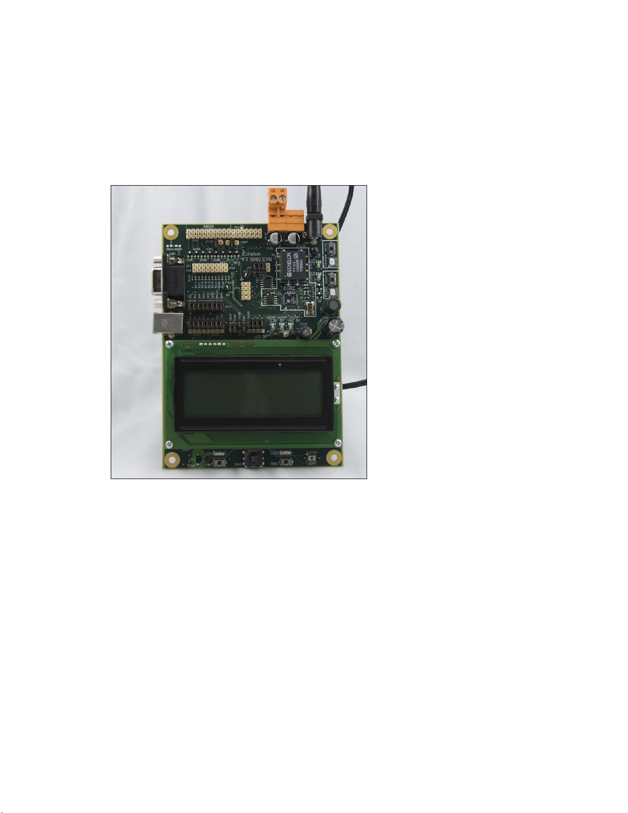
FT 5000 EVB Evaluation Board
The FT 5000 EVB is a complete 5000 Series LONWORKS device that you can use to evaluate the
ONWORKS 2.0 platform and create LONWORKS devices. The FT 5000 EVB includes a FT 5000
L
Smart Transceiver with an external 10 MHz crystal (you can adjust the system’s internal clock speed
from 5MHz to 80MHz), an FT-X3 communication transformer, 64KB external serial EEPROM and
flash memory devices, and a 3.3V power source. The FT 5000 EVB features a compact design that
includes the following I/O devices that you can use to develop prototype and production devices and
test the FT 5000 EVB example applications:
• 4 x 20 character LCD
• 4-way joystick with center push button
• 2 push-button inputs
• 2 LED outputs
• Light-level sensor
• Temperature sensor
The FT 5000 EVB Evaluation Board also includes EIA-232/TIA-232 (formerly RS-232) and USB
interfaces that you can use to connect the board to your development computer and perform
application-level debugging. You can also use the EIA-232 interface for development with the
ShortStack
Note: You cannot run ShortStack 2.1 Micro Servers on the FT 5000 EVB.
Each FT 5000 EVB also features a flash in-circuit emulator (ICE) header that supports the SPI and I
interfaces for fast downloads when programming the external non-volatile memory of the FT 5000
Smart Transceiver on the board.
For more information on the FT 5000 EVB hardware, including detailed descriptions of its Neuron
core, I/O devices, service pin and reset buttons and LEDs, and jumper settings, see the FT 50000 EVB
Hardware Guide.
®
Developer’s Kit. Note that only one interface can be used at a time.
Increased Network Variable Support
Neuron chips that use version 16 firmware or greater can support up to 254 static network variables
and 127 network variable aliases for Neuron-hosted devices, subject to available system resources (for
example, RAM and EEPROM) and application requirements. The 5000 Series chips use the new
version 18 Neuron firmware and therefore support these increased network variable limits, subject to
resources.
2
C
You must build the device application with the NodeBuilder FX tool to take advantage of these
increased network variable limits. If you use a previous release of the NodeBuilder tool, your device
application is limited to 62 network variables.
NodeBuilder FX User's Guide 5
Page 20

Neuron C Version 2.2 Enhancements
The new features in the Neuron C Version 2.2 programming language include interrupt support,
non-constant device-specific configuration properties, and new and enhanced compiler directives.
These new features are detailed in the Neuron C Programmer’s Guide and Neuron C Reference Guide.
Interrupt Support
The 5000 Series chips support hardware user interrupts in addition to the support provided through I/O
models. The Neuron C Version 2.2 language includes new keywords to manage hardware user
interrupts and a semaphore for application programs. The 5000 Series chips support the following
three types of interrupts: I/O interrupts, timer/counter driven interrupts, and periodic system interrupts.
When the 5000 Series chips are running at a system clock rate of 20 MHz or greater, these interrupts
execute in the separate interrupt processor on the chips, which improves the performance of the
interrupt and the device application.
Non-Constant Device-Specific Configuration Property Support
The Neuron C Version 2.2 language supports non-constant device-specific configuration properties.
Non-constant device-specific configuration properties have values that can be modified by the device
application, an LNS network tool such as the LonMaker tool, or another tool not based on LNS. For
example, a thermostat may include a user interface that allows the user to change the setpoint.
New and Enhanced Compiler Directives
The Neuron C Version 2.2 language includes new compiler directives and existing compiler directives
that have been enhanced to help you develop location-independent and modular code.
You can enable and disable specific errors and warnings using the new #error and #warning compiler
directives. You can use the new #pragma library directive to indicate custom library that is required.
You can use enhanced buffer control directives for statements of minimum or final requirements.
Compiler directives for control of the Neuron C Optimizer have been streamlined, and a new
optimization phase for generating more compact code has been added.
Enhanced Hardware Template Editor
The Hardware Template Editor in the NodeBuilder tool now supports hardware templates based on the
Neuron 5000 Processor or the FT 5000 Smart Transceiver, and is now available as a standalone tool.
For 5000 Series chips, you use the Hardware Template Editor to map external non-volatile memory
from 0x4000 to 0xE7FF in the Neuron address space (a maximum of 42 KB). The 5000 Series chips
support external serial EEPROM or serial flash devices for off-chip non-volatile memory. Echelon
currently supports and provides drivers for three flash devices (Atmel AT25F512AN, ST
M25P05-AVMN6T, and SST25VF512A).
For more information on using the Hardware Template Editor, see
Chapter 5.
Using Hardware Templates in
Enhanced Code Wizard Framework Template
The new Code Wizard Framework Version 3 Template supports large functional block and network
variable counts and includes fixes and improvements to code, code layout, and comments. New device
applications are automatically built using the Version 3 templates, and you can manually upgrade
existing applications to this version. The Code Wizard also supports continued maintenance of
applications based on Version 2 templates. For more information on upgrading existing device
applications to the new Code Wizard framework template, see
Chapter 6.
Using Code Wizard Templates in
6 Introduction
Page 21

Neuron C Debugger
The NodeBuilder debugger provides an option to write all breakpoints to RAM and not have them
copied to the external non-volatile memory. This option lets you set breakpoints and single step
through the memory of a 5000 Series Chip, without causing excessive writes to the external
non-volatile memory that could cause the memory to fail. For more information on using breakpoints
while debugging, see
Setting and Using Breakpoints in Chapter 10.
LNS Plug-in Framework Developer’s Kit
You can use the new LNS Plug-in Framework Developer’s Kit to write LNS device plug-ins in .NET
programming languages such as C# and Visual Basic .NET. The LNS Plug-in Framework Developer’s
Kit allows plug-ins to function in the .NET environment and interface with director applications. It
includes the .NET components needed for interfacing with the COM-based LNS API in the .NET
environment. It provides a set of example software and framework assemblies that let you efficiently
develop plug-ins with the latest .NET programming tools and re-distribute your plug-ins.
The LNS Plug-in Framework Developer’s Kit is automatically installed on your computer when you
install the NodeBuilder FX Development Tool CD. For more information on writing LNS device
plug-ins and the LNS Plug-in API, see the LNS Plug-in Programmer’s Guide.
Note: The LNS Plug-in Wizard, which generated code for Microsoft Visual Basic 6.0, has been
removed from the NodeBuilder tool and is no longer supported. You can still download the LNS
Plug-in Wizard from the Echelon Web site at
www.echelon.comdownloads.
Microsoft Windows Vista Support
The NodeBuilder FX Development Tool and the NodeBuilder online help files are compatible with
Microsoft Windows Vista.
What's Included with the NodeBuilder FX Tool
There are four NodeBuilder FX products: the NodeBuilder FX/FT Development Tool, the NodeBuilder
FX/PL Development Tool, the NodeBuilder FX/FT Classroom Edition, and the NodeBuilder FX CD.
The NodeBuilder FX/FT Classroom Edition is for educational-use only. The NodeBuilder FX CD is
for developers who do not require development hardware such as NodeBuilder 3.1 users or Mini FX
users who want to upgrade from an evaluation kit to a development kit (the NodeBuilder FX/FT Tool
and Mini FX/FT Kit both include FT 5000 EVBs). The four NodeBuilder FX products consist of the
following components:
Component
NodeBuilder Development Tool CD
Development Platforms*
LonMaker Integration Tool
Professional Edition CD (includes
Microsoft Visio 2003 Professional)
FX/FT and
FX/PL Tools
5 5 5
5 5
5 5
Classroom
Edition
CD
LonMaker Integration Tool Standard
Edition CD (includes Microsoft Visio
2003 Standard)
LonScanner Protocol Analyzer LNS
NodeBuilder FX User's Guide 7
5
5 5 5
Page 22
Turbo Edition CD
U10/U20 USB Network Interface
* The NodeBuilder FX/FT Development Tool and NodeBuilder FX/FT Classroom Edition include two FT 5000 EVBs. The
NodeBuilder FX/PL Tool includes one LTM-10A Hardware Platform and one NodeBuilder Gizmo 4 I/O Board (for
development of PL devices).
The following sections describe each of the components.
5 5
NodeBuilder FX Development Tool CD
The NodeBuilder Development Tool CD contains the software required to develop and debug Neuron
C applications for your L
can run on your development platform and use to further learn how to develop your own device
applications.
The NodeBuilder software includes the following components:
• NodeBuilder Resource Editor. View standard types and functional profiles, and create
user-defined types and profiles if the standard resource files do not include the resources you need.
• NodeBuilder Code Wizard. Use a drag-and-drop interface to create your device’s interface and
then automatically generate Neuron C source code that implements the device interface and
creates the framework for your device application.
• NodeBuilder Editor. Edit the Neuron C source code generated by the Code Wizard to create your
device’s application.
• NodeBuilder Debugger. Debug your application with a source-level view of your application code
as it executes.
ONWORKS devices, and it includes Neuron C example applications that you
• NodeBuilder Project Manager. Build and download your application image to your development
platform or to your own device hardware.
The NodeBuilder FX/FT Development tool and NodeBuilder FX/FT Classroom Edition include three
Neuron C example applications that you can run on your FT 5000 EVB, and the NodeBuilder FX/PL
Development tool includes one Neuron C example application that you can run on your LTM-10A
platform with Gizmo 4 I/O board. You can use these examples to test the I/O devices on the FT 5000
EVB or Gizmo 4 I/O board, and create simple L
code used in the example applications, and then create a new device application by modifying the
existing example applications or by developing the device application from scratch.
For more information on using the FT 5000 EVB example applications, see the FT 5000 EVB
Examples Guide. For more information on using the LTM-10A Platform–Gizmo 4 I/O Board example
application, see the NodeBuilder FX/PL Examples Guide.
ONWORKS networks. You can view the Neuron C
Development Platforms
The NodeBuilder FX/FT Development Tool includes two FT 5000 EVBs. The NodeBuilder FX/PL
Development Tool includes the LTM-10A Hardware Platform, a PLM-22 power line transceiver,
power line couplers for line-to-earth coupling and line-to-neutral coupling, and the NodeBuilder
Gizmo 4 I/O Board. The following sections describe these development platforms.
FT 5000 EVB Evaluation Board
The FT 5000 EVB is a complete 5000 Series LONWORKS device that you can use to evaluate the
ONWORKS 2.0 platform and create LONWORKS devices. The FT 5000 EVB includes an FT 5000
L
Smart Transceiver with an external 10 MHz crystal (you can adjust the system’s internal clock speed
from 5MHz to 80MHz), an FT-X3 communication transformer, 64KB external serial EEPROM and
flash memory devices, and a 3.3V power source. The FT 5000 EVB features a compact design that
8 Introduction
Page 23
includes the following I/O devices that you can use to develop prototype and production devices and
test the FT 5000 EVB example applications:
• 4 x 20 character LCD
• 4-way joystick with center push button
• 2 push-button inputs
• 2 LED outputs
• Light-level sensor
• Temperature sensor
The FT 5000 EVB Evaluation Board also includes an EIA-232/TIA-232 (formerly RS-232) and USB
interfaces that you can use to connect the board to your development computer and perform
application-level debugging. You can also use the RS-232 interface for development with the
ShortStack
®
Developer’s Kit. Note that only one interface can be used at a time.
Note: You cannot run ShortStack 2.1 Micro Servers on the FT 5000 EVB.
2
Each FT 5000 EVB also features a flash ICE header that supports the SPI and I
C interfaces for fast
downloads when programming the external non-volatile memory of the FT 5000 Smart Transceiver on
the board.
For more information on the FT 5000 EVB hardware, including detailed descriptions of its Neuron
core, I/O devices, service pin and reset buttons and LEDs, and jumper settings, see the FT 50000 EVB
Hardware Guide.
LTM-10A Platform and NodeBuilder Gizmo 4 I/O Board
The NodeBuilder FX/PL Development Tool includes the LTM-10A Hardware Platform (right) and the
NodeBuilder Gizmo 4 I/O Board (left).
NodeBuilder FX User's Guide 9
Page 24

LTM-10A Platform
The LTM-10A Platform is a complete LONWORKS device with downloadable flash memory and RAM
that you can use for testing your applications and I/O hardware prototypes.
The LTM-10A Platform includes an LTM-10A Flash Control Module (herein referred to as the
LTM-10A module) that you can design into your prototypes and products. The LTM-10A module
includes a Neuron Chip, 64 KB flash memory, 32 KB static RAM, 10 MHz crystal oscillator, and
custom Neuron firmware. The custom firmware allocates the memory to the Neuron Chip 64 KB
address space and automatically initializes the transceiver interface for standard transceivers. The
NodeBuilder tool can load your application image into the RAM or flash memory of the LTM-10A
module. An application image loaded into the flash memory is preserved when the module is powered
down. An application image loaded into the RAM is preserved when the module is reset, but not when
it is powered down. You can use the Neuron C Debugger to debug applications running in the RAM
or flash memory; however, you should debug your application running in RAM because extensive
debugging in the flash memory can cause the flash memory to fail.
The LTM-10A Platform also includes a PLM-22 power line transceiver with external power line
coupler for attaching the platform to a L
ONWORKS network. Two power line couplers are included,
one for line-to-earth coupling and one for line-to-neutral coupling.
For more information on the LTM-10A Platform and Flash Control Module, see the LTM-10A User’s
Guide.
NodeBuilder Gizmo 4 I/O Board
The NodeBuilder Gizmo 4 I/O Board is a collection of I/O devices that you can use with the LTM-10A
Platform for developing prototype devices and I/O circuits, developing special-purpose devices for
testing, or running the NodeBuilder examples. The Gizmo 4 includes the following I/O devices:
• 4 x 20 character LCD display
• 2 10-bit resolution analog inputs with screw terminal connector
• 2 8-bit resolution analog outputs with screw terminal connector
• 2 digital inputs with screw terminal connector and pushbutton inputs
• 2 digital outputs with screw terminal connector and LED outputs
• Digital shaft encoder
• Piezoelectric transducer
• Real-time clock
• Temperature sensor
10 Introduction
Page 25

A Gizmo 4 I/O library is included with the NodeBuilder software that provides easy-to-use high-level
functions for accessing the display, analog I/O, piezo transducer, real-time clock, and temperature
sensor. For a description of the I/O devices on the Gizmo 4 board and a description of the Gizmo 4 I/O
library, see the Gizmo 4 User’s Guide.
LonMaker Integration Tool CD
The LonMaker tool is an integral part of your NodeBuilder development kit that you can use to install,
connect, configure, test, and update the devices in your project. It is a software package for designing,
installing, and maintaining L
system, the LonMaker tool combines a powerful, client-server architecture with an easy-to-use Visio
user interface. The LonMaker tool is compatible with a number of LNS plug-ins, including the
NodeBuilder Project Manager.
The LonMaker tool can be used to manage all phases of a network’s life cycle, from the initial design
and commissioning to the ongoing operation, because it provides the functionality of several network
tools in one single solution:
• Network Design Tool. You can design a network onsite or offsite (either connected to the network
over the Internet or not connected to it all), and then modify it anytime. The LonMaker tool can
also learn an existing network’s design through a process called network recovery.
• Network Installation Tool. You can rapidly install a network designed offsite once it is brought
onsite. The device definitions can be quickly and easily associated with their corresponding
physical devices to reduce on-site commissioning time. The LonMaker Browser provides
complete access to all network variables and configuration properties.
ONWORKS control networks. Based on Echelon’s LNS network operating
• Network Documentation Tool. You can create a LonMaker drawing during the network design
and installation process. This LonMaker drawing is an accurate, logical representation of the
installed physical network. The LonMaker drawing is therefore an essential component of as-built
reports.
• Network Operation Tool. You can operate the network using the operator interface pages
contained within the LonMaker drawing.
• Network Maintenance Tool. You can easily add, test, remove, modify, or replace devices, routers,
channels, subsystems, and connections to maintain the network.
This guide describes many of the LonMaker functions that you will use with the NodeBuilder tool.
See the LonMaker User’s Guide for more information on the LonMaker tool and to learn how it can be
used to install, operate, and maintain your operational networks in addition to your development
networks.
LonScanner Protocol Analyzer CD
The LonScanner Protocol Analyzer is a software package that provides network diagnostic tools to
observe, analyze, and diagnose the behavior of installed L
devices that you have built with the NodeBuilder tool. You can use the LonScanner tool with the U10
or U20 USB network interface included with the NodeBuilder FX/FT and FX/PL Tools, and you also
use it with other network interfaces including an IP-852 (ISO/IEC 14908-4) interface as described in
the LonScanner Protocol Analyzer User’s Guide. For more information on the LonScanner tool, see
the LonScanner Protocol Analyzer User’s Guide.
ONWORKS networks, including network with
U10/U20 USB Network Interface
The NodeBuilder FX/FT Development Tool and NodeBuilder FX/PL Development Tool include U10
and U20 USB network interfaces, respectively. The U10 and U20 USB Network Interfaces are
low-cost, high-performance L
NodeBuilder FX User's Guide 11
ONWORKS interfaces for USB-enabled computers and controllers.
Page 26

The U10 USB Network Interface connects directly to TP/FT-10 Free Topology Twisted Pair (ISO/IEC
14908-2) L
Interface connects to PL-20 C-Band Power Line (ISO/IEC 14908-3) L
ONWORKS channels through a high-quality removable connector. The U20 USB Network
ONWORKS channels through an
included power supply with integrated coupler. The U20 USB Network Interface can also be
connected directly to 10.8-18VDC power systems (such as those in automobiles, trucks and buses)
without a coupling circuit, or to virtually any powered line through a customer-supplied coupler/power
supply.
The drivers for U10 and U20 USB network interfaces are automatically installed on your computer
when you install the LonMaker Integration Tool CD.
The USB Network Interfaces can be used with virtually any computer-based L
including all LNS
and OpenLDV
™
based applications such as the NodeBuilder Development tool,
ONWORKS application,
LonMaker tool, and LonScanner Protocol Analyzer.
For more information on installing and using the U10 and U20 USB network interfaces, see the
LonWorks USB Network Interface User’s Guide.
Introduction to NodeBuilder Device Development and LONWORKS Networks
A LONWORKS network consists of intelligent devices (such as sensors, actuators, and controllers) that
communicate with each other using a common protocol over one or more communications channels.
Network devices are sometimes called nodes.
Devices may be Neuron hosted or host-based. Neuron hosted devices run a compiled Neuron C
application on a Neuron Chip or Smart Transceiver. You can use the NodeBuilder tool to develop,
test, and debug Neuron C applications for Neuron hosted devices.
Host-based devices run applications on a processor other than a Neuron Chip or Smart Transceiver.
Host-based devices may run applications written in any language available to the processor. A
host-based device may use a Neuron Chip or Smart Transceiver as a communications processor, or it
may handle both application processing and communications processing on the host processor. The
NodeBuilder tool supports some of the common tasks occurring in the creation of host-based devices;
however, an additional host-based device development tool, such as the ShortStack
Kit or the FTXL
™
Developer’s Kit, is required.
®
2.1 Developer’s
Each device includes one or more processors that implement the ISO/IEC
14908-1 Control Network
Protocol (CNP). Each device also includes a component called a transceiver to provide its interface to
the communications channel.
A device publishes and consumes information as instructed by the application that it is running. The
applications on different devices are not synchronized, and it is possible that multiple devices may all
try to talk at the same time. Meaningful transfer of information between devices on a network,
therefore, requires organization in the form of a set of rules and procedures. These rules and
procedures are the communication protocol, which may be referred to simply as the protocol. The
protocol defines the format of the messages being transmitted between devices and defines the actions
expected when one device sends a message to another. The protocol normally takes the form of
embedded software or firmware code in each device on the network. The CNP
is an open protocol
defined by the ISO/IEC 14908-1 standard (defined nationally in the United States, Europe, and China
by the ANSI/EIA 709.1, EN 14908, and GB/Z 20177 standards, respectively).
Channels
A channel is the physical media between devices upon which the devices communicate. The LonTalk
protocol is media independent; therefore, numerous types of media can be used for channels: twisted
pair, power line, fiber optics, IP, and radio frequency (RF) to name a few. Channels are categorized
into channel types, and the channel types are characterized by the device transceiver. Common
12 Introduction
Page 27

channel types include TP/FT-10 (ISO/IEC 14908-2 twisted pair free topology channel), TP/XF-1250
(high-speed twisted pair channel), PL-20 (ISO/IEC 14908-3 power line channel), FO-20
(ANSI/CEA-709.4 fiber optics channel), and IP-852 (ISO/IEC 14908-4 IP-communication).
Different transceivers may be able to interoperate on the same channel; therefore, each transceiver type
specifies the channel type or types that it supports. The choice of channel type affects transmission
speed and distance as well as the network topology.
The NodeBuilder tool, LonMaker tool, and LonScanner tool, and Neuron chips support all standard
channel types, but not all Neuron chips support all transceiver and channel types. Smart Transceivers
combine the transceiver and Neuron chip core in the same chip, and therefore support the channel
types supported by the integrated transceiver.
Routers
Multiple channels can be connected using routers. Routers are used to manage network message
traffic, extend the physical size of a channel (both length and number of devices attached), and connect
channels that use different media (channel types) together. Unlike other devices, routers are always
attached to at least two channels.
The NodeBuilder tool does not require routers, but the LonMaker tool can be used to create complex
networks that include multiple routers. Typically, device development networks use a simple
topology, but you can create a complex network when creating a device application with the
NodeBuilder tool.
Applications
Every LONWORKS device contains an application that defines the device’s behavior. The application
defines the inputs and outputs of the device. The inputs to a device can include information sent on
ONWORKS channels from other devices, as well as information from the device hardware (for
L
example, the temperature from a temperature sensing device). The outputs from a device can include
information sent on L
hardware (for example, a fan, light, heater, or actuator). You can use the NodeBuilder tool to write a
device’s Neuron C application.
ONWORKS channels to other devices, as well as commands sent to the device
Program IDs
Every LONWORKS application has a unique, 16 digit, hexadecimal Standard Program ID with the
format FM:MM:MM:CC:CC:UU:TT:NN. This Program ID is broken down into the following
fields:
Field Description
Format (F)
A 1 hex-digit value defining the structure of the program ID. The upper
bit of the format defines the program ID as a standard program ID (SPID)
or a text program ID. The upper bit is set for standard program IDs, so
formats 8–15 (0x8–0xF) are reserved for standard program IDs.
• Program ID format 8 is reserved for L
• Program ID format 9 is used for devices that will not be L
certified, or for devices that will be certified but are still in
development or have not yet completed the certification process.
ONMARK certified devices.
ONMARK
• Program ID formats 10–15 (0xA–0xF) are reserved for future use.
Text program ID formats are used by network interfaces and legacy
devices and, with the exception of network interfaces, should not be
used for new devices.
The NodeBuilder tool can be used to create applications with program ID
NodeBuilder FX User's Guide 13
Page 28

Field Description
format 8 or 9.
Manufacturer ID (M)
Device Class (C)
Usage (U)
A 5 hex-digit ID that is unique to each L
ONWORKS device manufacturer.
The upper bit identifies the manufacturer ID as a standard manufacturer
ID (upper bit clear) or a temporary manufacturer ID (upper bit set).
• Standard manufacturer IDs are assigned to manufacturers when they
ONMARK International, and are also published by LONMARK
join L
International so that the device manufacturer of a L
ONMARK certified
device is easily identified. Standard manufacturer IDs are never
reused or reassigned. If your company is a L
ONMARK member, but
you do not know your manufacturer ID, you can find your ID in the
list of manufacturer IDs at
www.lonmark.org/spid. The most current
list at the time of release of the NodeBuilder tool is also included with
the NodeBuilder software.
• Temporary manufacturer IDs are available at no charge to anyone on
request by filling out a simple form at
www.lonmark.org/mid.
A 4 hex-digit value identifying the primary function of the device. This
value is drawn from a registry of pre-defined device class definitions. If
an appropriate device class designation is not available, L
ONMARK
International Secretary will assign one, upon request.
A 2 hex-digit value identifying the intended usage of the device. The
upper bit specifies whether the device has a changeable interface. The
next bit specifies whether the remainder of the usage field specifies a
standard usage or a functional-profile specific usage. The standard usage
values are drawn from a registry of pre-defined usage definitions. If an
appropriate usage designation is not available one will be assigned upon
request. If the second bit is set, a custom set of usage values is specified
by the primary functional profile for the device.
Channel Type (T)
A 2 hex-digit value identifying the channel type supported by the device’s
ONWORKS transceiver. The standard channel-type values are drawn
L
from a registry of pre-defined channel-type definitions. A custom
channel-type is available for channel types not listed in the standard
registry.
Model Number (N)
A 2 hex-digit value identifying the specific product model. Model
numbers are assigned by the product manufacturer and must be unique
within the device class, usage, and channel type for the manufacturer. The
same hardware may be used for multiple model numbers depending on the
program that is loaded into the hardware. The model number within the
program ID does not have to conform to your published model number.
See the
LonMark Application Layer Interoperability Guidelines for more
information about program IDs.
Network Variables
Applications exchange information with other LONWORKS devices using network variables. Every
network variable has a direction, type, and length. The network variable direction can be either input
or output, depending on whether the network variable is used to receive or send data. The network
variable type determines the format of the data.
14 Introduction
Page 29

Network variables of identical type and length but opposite directions can be connected to allow the
devices to share information. For example, an application on a lighting device could have an input
network variable that was of the switch type, while an application on a dimmer-switch device could
have an output network variable of the same type. A network management tool such as the LonMaker
Integration Tool could be used to connect these two devices, allowing the switch to control the lighting
device, as shown in the following figure:
A single network variable may be connected to multiple network variables of the same type but
opposite direction. The following example shows the same switch being used to control three lights:
The application program in a device does not need to know where input network variable values come
from or where output network variable values go. When the application program has a changed value
for an output network variable, it simply assigns the new value to the output network variable.
Through a process called binding that takes place during network design and installation, the device is
configured to know the logical address of the other device or group of devices in the network
expecting that network variable’s values. The device’s embedded firmware assembles and sends the
appropriate packet(s) to these destinations. Similarly, when the device receives an updated value for
an input network variable required by its application program, its firmware passes the data to the
application program. The binding process thus creates logical connections between an output network
variable in one device and an input network variable in another device or group of devices.
Connections may be thought of as virtual wires. For example, the dimmer-switch device in the
dimmer-switch-light example could be replaced with an occupancy sensor, without making any
changes to the lighting device.
The NodeBuilder Code Wizard automatically generates the required network variable declarations for
your device’s interface in your device’s Neuron C application. Typically, you don’t need implement
any code in the device application to handle the binding process, or the source or destination devices
NodeBuilder FX User's Guide 15
Page 30

for network variable values. Neuron C provides an easy-to-use programming model familiar to any C
language programmer that encapsulates the complexity of distributed applications.
Configuration Properties
LONWORKS applications may also contain configuration properties. Configuration properties allow
the device’s behavior to be customized using a network management tool such as the LonMaker tool or
a customized plug-in created for the device (see the LNS Plug-in Programmer’s Guide for more
information on creating LNS device plug-ins).
For example, an application may allow an arithmetic function (add, subtract, multiply, or divide) to be
performed on two values received from two network variables. The function to be performed could be
determined by a configuration property. Another example of a configuration property is a heartbeat
that determines how often a device transmits network variable updates over the network.
Like network variables, configuration properties have types that determine the type and format of the
data they contain.
The NodeBuilder Code Wizard automatically generates the required configuration property
declarations for your device’s interface and most of the required infrastructure code in your device’s
Neuron C application. The NodeBuilder tool supports configuration properties with an easy-to-use
programming model in Neuron C.
Functional Blocks
Applications in devices are divided into one or more functional blocks. A functional block is a
collection of network variables and configuration properties, which are used together to perform one
task. These network variables and configuration properties are called the functional block members.
For example, a digital input device could have four digital input functional blocks that contain the
configuration properties and output network variable members for each of the four hardware digital
inputs on the device.
The NodeBuilder Code Wizard automatically generates the required functional block declarations for
your device’s interface in your device’s Neuron C application.
A functional block is an implementation of a functional profile.
Functional Profiles
A functional profile defines mandatory and optional network variable and configuration property
members for a type of functional block. For example, the standard functional profile for a light
actuator has mandatory SNVT_switch input and output network variables, optional
SNVT_elapsed_tm and SNVT_elec_kwh output network variables, and a number of optional
configuration properties. The following diagram illustrates the components of the standard light
actuator functional profile:
16 Introduction
Page 31

When a functional block is created from a functional profile, the application designer can determine
which of the optional configuration properties and network variables to implement.
Hardware Templates
A hardware template is a file with a .NbHwt extension that defines the hardware configuration for a
device. It specifies hardware attributes that include the transceiver type, Neuron Chip or Smart
Transceiver model, clock speed, system image, and memory configuration. Several hardware
templates are included with the NodeBuilder tool. You can use these or create your own. Third-party
development platform suppliers may also include hardware templates for their platforms.
Neuron C
Neuron C is a programming language, based on ANSI C, used to develop applications for devices that
use a Neuron Chip or Smart Transceiver as the application processor. Neuron C includes extensions
for network communication, device configuration, hardware I/O, and event-driven scheduling.
Device Templates
A device template defines a device type. The NodeBuilder tool uses two types of device templates.
The first is a NodeBuilder device template. The NodeBuilder device template is a file with a .NbDt
extension that specifies the information required for the NodeBuilder tool to build the application for a
device. It contains a list of the application Neuron C source files, device-related preferences, and the
hardware template name. When the application is built, the NodeBuilder tool automatically produces
an LNS device template and passes it to the LonMaker tool and other network tools. The LNS device
template defines the external device interface, and it is used by the LonMaker tool and other network
tools to configure and bind the device.
Device Interface Files
A device interface file (also known as an XIF file or an external interface file) is a file that specifies the
interface of a device. It includes a list of all the functional blocks, network variables, configuration
properties, and configuration property default values defined by the device’s application. LNS tools
such as the LonMaker tool use device interface files to create an LNS device template. This enables
the network tool to be used to create network designs without being connected to the physical devices,
and it speeds up some configuration steps when the network tool is connected to the physical device.
NodeBuilder FX User's Guide 17
Page 32

A text device interface file with a .XIF extension is required by the
LonMark Application Layer
Interoperability Guidelines. A text device interface file is automatically produced by the NodeBuilder
tool when you build an application. The NodeBuilder tool also automatically creates binary (.XFB
extension) and optimized-binary (.XFO extension) versions of the device interface file that speed the
import process for LNS tools such as the LonMaker tool.
Resource Files
Resource files define network variable types, configuration property types, and functional profiles.
Resource files for standard types and profiles are distributed by L
resource files define standard network variable types (SNVTs), standard configuration property types
(SCPTs), and standard functional profiles. For example, SCPT_location is a standard configuration
property type for configuration properties containing the device location as a text string, and
SNVT_temp_f is a network variable type for network variables containing temperature as a
floating-point number. The standard network variable and configuration property types are defined at
types.lonmark.org.
As new SNVTs and SCPTs are defined, updated resource files and documentation are posted to the
ONMARK Web site. Standard functional profiles are included with the NodeBuilder tool, and their
L
documentation is also available on the L
files and documentation, go to the L
ONMARK Web site. To view and download the latest resource
ONMARK Web site at www.lonmark.org.
Device manufacturers may also create user resource files that contain manufacturer-defined types and
profiles called user network variable types (UNVTs), user configuration property types (UCPTs), and
user functional profiles (UFPTs).
You can create applications that only use the standard types and profiles. In this case, you do not need
to create user-defined resource files. If you need to define any new user types or profiles, you will use
the NodeBuilder Resource Editor to create them.
ONMARK International. The standard
Targets
A target is a LONWORKS device whose application is built by the NodeBuilder tool. There are two
types of targets, development targets and release targets. Development targets are used during
development; release targets are used when development is complete and the device will be released to
production. Each NodeBuilder device template specifies the definition for a development target and a
release target. Both target definitions use the same source code, program ID, interface, and resource
files, but can use different hardware templates and compiler, linker, and exporter options. The source
code may include code that is conditionally compiled based on the type of target.
18 Introduction
Page 33

Installing the NodeBuilder FX
Development Tool
This chapter describes how to get started with your NodeBuilder tool, including how
to install the NodeBuilder software and connect the NodeBuilder hardware.
2
NodeBuilder FX User's Guide 19
Page 34

Installing the NodeBuilder FX Development Tool
To install your NodeBuilder FX Development Tool, follow these steps:
1. Verify that you have a manufacturer ID. A manufacturer ID is required for many NodeBuilder
tool functions.
Standard manufacturer IDs are assigned to manufacturers when they join L
and are also published by L
certified device is easily identified. If your company is a L
know your manufacturer ID, you can go to
ONMARK International so that the device manufacturer of a LONMARK
ONMARK member, but you do not
www.lonmark.org/spid and find your ID in the list of
ONMARK International,
manufacturer IDs. The most current list at the time of release of the NodeBuilder tool is also
included with the NodeBuilder software.
If you do not have a manufacturer ID, you can instantly get a temporary manufacturer ID by filling
out a simple form at
http://www.lonmark.org/mid.
2. If you have Mini EVK 1.0 installed on your computer, remove it before installing the NodeBuilder
FX software.
3. Register your NodeBuilder FX tool. This entitles you to a free replacement CD or serial number if
you lose either one in the future. To register your NodeBuilder FX tool, go to
www.echelon.com/register, select the NodeBuilder product, enter the serial number from the back
of your NodeBuilder FX Tool CD case, enter the other information requested by the form, and
then click Register Now.
*** SPECIAL OFFER *** Echelon will send you free printed versions of the Neuron C
Programmer’s Guide and the Neuron C Reference Guide if you register your software within
30 days of purchase.
4. Insert the LonMaker Integration Tool CD into your computer, install the LonMaker software,
and then activate the LonMaker tool as described in Chapter 2 of the LonMaker User’s Guide.
The LonMaker tool must be installed on your computer in order to install the NodeBuilder
software.
Installing the LonMaker tool automatically installs the drivers for the U10/U20 USB network
interface (included with the NodeBuilder FX Development Tool); PCC-10 PC Card Network
Interface; PCLTA-20 and 21 Cards; the i.LON SmartServer, i.LON 100 Internet Server, and
i.LON 10 Ethernet Adapter remote network interfaces; and the i.LON 600 L
ONWORKS-IP Server.
If you are using an SLTA-10 Serial LonTalk Adapter as the network interface, select the check
box for installing the SLTA-10 driver in the LonMaker installer as described in the LonMaker
User’s Guide.
5. Insert the LonScanner Protocol Analyzer CD into your computer, install the LonScanner
software, and then activate the LonScanner software as described in the LonScanner Protocol
Analyzer User’s Guide.
Note: You must install the LonScanner software before installing the NodeBuilder FX software;
otherwise, the NodeBuilder FX tool may fail.
6. Insert the NodeBuilder FX Development Tool CD into your computer and install the
NodeBuilder software as described in the next section,
Installing the NodeBuilder Software. You
must install Microsoft .NET Framework 3.5 SP1, the NodeBuilder FX tool, and LNS
Server/Turbo Edition SP5, in that order, to run the NodeBuilder tool. Optionally, you can install
Adobe Reader 9.1, and you can install the provided FTDI USB driver if you plan on using the
USB port on the NodeBuilder FX/FT hardware (FT 5000 EVB) for debugging.
Note: The NodeBuilder software automatically installs the following programs on your computer:
NodeBuilder Resource Editor 4.0, L
ONMARK Resource Files 13.00, LNS Plug-in Framework 1.10,
and ISI Developer’s Kit 3.02.
20 Installing the NodeBuilder Development Kit
Page 35

7. Connect the NodeBuilder hardware as described in
this chapter.
8. If you do not have the LonMaker FX tool, which is scheduled to be released in 2010, or you are
developing 3100 Series devices, order 500 LonMaker development credits as described in Chapter
10 of the LonMaker User’s Guide. You do not need to order LonMaker credits if you have the
LonMaker FX tool and you are developing 5000 Series devices.
Your licensed copy of the LonMaker software includes 64 free LonMaker credits. A LonMaker
credit is a token representing a prepaid fee to commission a device. You can use LonMaker
credits in one network or in multiple networks. LonMaker credits are associated with the
LonMaker application and the computer running it and are stored in a file called the LonMaker
license file. The LonMaker tool keeps track of the number of credits you have available. When
you initially install the LonMaker tool, you have 64 free LonMaker credits to start your
development. You can order up to 500 free credits for development use per year per device type
that you develop.
9. If you will be developing an LNS device plug-in for your device, install Microsoft Visual Studio
2005 Professional Edition or higher. The NodeBuilder software installer automatically installs the
new LNS Plug-in Framework Developer’s Kit, which you can use to write LNS device plug-ins in
.NET programming languages such as C# and Visual Basic .NET For more information on writing
LNS device plug-ins and the LNS Plug-in API, see the LNS Plug-in Programmer’s Guide.
Connecting the NodeBuilder Hardware later in
Installing the NodeBuilder Software
To install the NodeBuilder software, follow these steps:
1. Insert the NodeBuilder FX Development Tool CD into your CD-ROM drive.
2. If the NodeBuilder setup application does not launch immediately, click Start on the taskbar and
then and click Run. Browse to the Setup application on the NodeBuilder FX Development Tool
CD and click Open. The Echelon NodeBuilder FX Development Tool main menu opens.
3. Click Install Products. The Install Products dialog opens.
NodeBuilder FX User's Guide 21
Page 36

4. Click Microsoft .NET Framework 3.5 SP1 to install Microsoft .NET Framework 3.5 SP1 and
then follow the on-screen instructions. Microsoft .NET Framework 3.5 SP1 is required to run the
NodeBuilder tool.
5. After Microsoft .NET Framework 3.5 SP1is installed, click the Echelon NodeBuilder FX
Development Tool button in the Taskbar to return to the NodeBuilder installer, and then click
NodeBuilder FX in the Install Products dialog. The Welcome window of the NodeBuilder
software installer opens.
6. Click Next. The NodeBuilder Development Tool License Agreement window opens.
22 Installing the NodeBuilder Development Kit
Page 37

7. Read the license agreement (see Appendix D,
printed version of this license agreement). If you agree with the terms, click Accept the Terms
and then click Next. The Customer Information window appears.
NodeBuilder Software License Agreement, for a
8. Enter the NodeBuilder serial number on the back of NodeBuilder FX Development Tool CD in the
Serial Number box. Optionally, you can enter the following registration information. The
NodeBuilder FX tool automatically enters this information into your resource files. Your phone
number, e-mail address, and Web address will be included with any resource file that you create
and distribute.
User Name Your name. The name may be entered automatically based on the user
currently logged on and whether other Echelon products are installed on
NodeBuilder FX User's Guide 23
Page 38

your computer.
Organization The name of your company. The name may be entered automatically
based on the user currently logged on and whether other Echelon
products are installed on your computer.
Manufacturer ID If you have a standard manufacturer ID, enter it decimal format.
If your company is a L
ONMARK member, but you do not know your
manufacturer ID, you can find your ID in the list of manufacturer IDs at
www.lonmark.org/spid. The most current list at the time of release of
the NodeBuilder tool is also included with the NodeBuilder software.
If you do not have a standard manufacturer ID, you can request a
temporary manufacturer ID by filling out a simple form at
www.lonmark.org/mid.
Phone Number The phone number where you can be contacted.
Email Address The e-mail address where you can be contacted.
Web Address Your company’s Web site.
Note: You can enter or modify this information after installing the NodeBuilder software in the
NodeBuilder Project Manager. To do this, create or open a NodeBuilder project, click Project,
click Settings (or right-click the Project folder in the Project pane and click Settings on the
shortcut menu), and then click the Registration tab in the NodeBuilder Project Properties
dialog.
9. Click Next. If your computer does not have a L
window appears. Choose a L
ONWORKS folder in which you want the NodeBuilder software
ONWORKS directory, the Destination Location
installed. By default, the NodeBuilder software is installed in the C:\LonWorks folder, or the
C:\Program Files\LonWorks directory if you have not previously installed any Echelon or
ONMARK products (this will not likely be the case because you should have already installed the
L
LonMaker tool, which is installed in the C:\LonWorks folder by default). Click Next.
10. The Setup Type window opens.
24 Installing the NodeBuilder Development Kit
Page 39

11. Select the type of installation to be performed. Select Complete to install NodeBuilder features or
select Custom to choose whether to install the FT 5000 EVB examples, NodeBuilder LTM-10A
examples, both sets of examples, or neither on your computer. Click Next. The Ready to Install
window appears.
12. Click Install to begin the NodeBuilder software installation. Before installing the NodeBuilder
software, the following programs are automatically installed or upgraded on your computer (if
they are not already installed on your computer, or if they are installed, but have a lower version):
NodeBuilder Resource Editor 4.0, L
ONMARK Resource Files 13.00, LNS Plug-in Framework 1.10,
and ISI Developer’s Kit 3.02.
13. After the NodeBuilder software has been installed, a window appears stating that the installation
has been completed successfully.
NodeBuilder FX User's Guide 25
Page 40

14. Click Finish. If a window appears prompting you to reboot your computer now or later, click Yes
to reboot your computer now.
15. Once the installation has completed, you will be given the option to view the ReadMe file. See
the ReadMe file for updates to the NodeBuilder documentation.
16. Install LNS Server/Turbo Edition SP5 after the NodeBuilder tool is installed and you have
performed any required reboots. To do this, click the Echelon NodeBuilder FX Development
Tool button in the Taskbar to return to the NodeBuilder installer, click LNS Turbo SP 5 in the
Install Products dialog, and then follow the on-screen instructions. LNS Server/Turbo Edition
SP5 or later is required for developing, testing, and debugging your devices.
17. Optionally, install Adobe Reader 9.1. Adobe Reader (or another PDF viewer) is required to open
the user documentation PDF files included with the NodeBuilder software. To do this, click the
Echelon NodeBuilder FX Development Tool button in the Taskbar to return to the NodeBuilder
installer, click Adobe Reader 9.1 in the Install Products dialog, and then follow the on-screen
instructions.
18. Optionally, install the FTDI USB driver if you plan on using the USB port on the FT 5000 EVB
for debugging. To do this, click the Echelon NodeBuilder FX Development Tool button in the
Taskbar to return to the NodeBuilder installer, and then click FTDI USB Driver 2.04.06 in the
Install Products dialog.
Connecting the NodeBuilder Hardware
The following sections describe how to connect the NodeBuilder FX/FT hardware (FT 5000 EVBs)
and the NodeBuilder FX/PL hardware (LTM-10A Platform, Gizmo 4 I/O Board, and power line
coupler).
Connecting the NodeBuilder FX/FT Hardware
To connect the NodeBuilder FX/FT hardware, follow these steps:
1. Unpack the equipment from the shipping carton.
Note: The FT 5000 EVBs are shipped in protective anti-static packaging. When assembling the
FT 5000 EVBs, the boards must not be subjected to high electrostatic potentials. Avoid touching
the component pins, or any other metallic equipment on the evaluation boards.
2. Verify that all of the following hardware and software items are present.
Item Qty
FT 5000 EVB 2
Power supplies (90–240VAC 50/60Hz) with power cords (US/Japan and
Continental European)
Network cable and terminator 1
U10 USB Network Interface 1
USB Extension Cable 1
NodeBuilder FX CD 1
2
LonMaker CD 1
LonScanner CD 1
3. Connect the barrel connectors of the included power supplies into the barrel jacks on the FT 5000
EVBs, connect the power supplies to the included power cords that are appropriate for you region
(US/Japan or Continental European), and then plug the power cords into a power outlet. The
power LEDs on the boards will activate when they are powered on.
26 Installing the NodeBuilder Development Kit
Page 41

4. Connect the orange network connector on each FT 5000 EVB to the included network cable.
5. Use the included U10 USB Network Interface to attach the computer running the NodeBuilder
tool to the TP/FT-10 channel. To do this, connect the black network connector on the network
cable to the U10 USB Network Interface, and then plug the U10 USB Network Interface into an
available USB port on your computer. You can use the included USB extension cable to help
connect the USB 10 Network Interface to your development computer.
NodeBuilder FX User's Guide 27
Page 42

If this is the only L
ONWORKS interface installed on your computer, it will automatically use the
default name LON1, and you can proceed directly to your software application and begin using
the interface as LON1.
If you have another network interface installed on your computer, you can check the name used by
the U10 USB Network Interface in the L
ONWORKS Interfaces application. You can also use this
application to configure the buffer sizes and counts used by the U10 USB Network Interface. To
open the L
ONWORKS Interfaces application, and check the name of the U10 USB Network
Interface and configure it, click Start on the taskbar, click Control Panel, double-click
LonWorks
Interfaces, and then click the USB tab.
For more information on installing and using the U10 USB Network Interface, see the LonWorks
USB Network Interface User’s Guide.
Note: You can use a different network interface such as a PCC-10, PCLTA-20, or PCLTA-21;
SLTA-10; remote network interface (i.LON SmartServer, i.LON 100 Internet Server, i.LON 600
ONWORKS-IP Server, or i.LON 10 Ethernet Adapter); or an IP-852 interface (i.LON
L
SmartServer with IP-852 routing, i.LON 100 Internet Server with IP-852 routing, or i.LON 600
ONWORKS-IP Server).
L
To use a PCC-10, a PCLTA-20, or a PCLTA-21 as the network interface, you first need to
configure it as a layer-2 network interface using the L
ONWORKS Plug ‘n Play application. To do
this, click Start on the taskbar, click Control Panel, and then double-click LonWorks Plug ‘n
Play. In the Device Selected box, select your network interface. In the NI application box,
select PCC10NSI if you are using a PCC-10, or select NSIPCLTA if you are using a PCLTA-20
or a PCLTA-21. Click OK to save your changes and close the LonWorks Plug ‘n Play
application.
6. Complete the quick-start exercise in Chapter 3,
NodeBuilder Quick-Start Exercise. In the
quick-start exercise, you will develop a device with one sensor and one actuator. The sensor is a
simple sensor that monitors a push button on the FT 5000 EVB and toggles a network variable
output each time the button is pressed. The actuator drives the state of an LED on the FT 5000
EVB based on the state of a network variable input.
This quick-start guides you through all the steps of creating a device with the NodeBuilder tool,
including creating the NodeBuilder project, the device template, the device interface, and the
Neuron C code that implements your device interface; implementing device functionality in the
Neuron C code; building and downloading the device application; testing the device in a
ONWORKS network; and debugging the device application.
L
7. Run the Neuron C example applications included with the NodeBuilder FX tool on your FT 5000
EVBs. The NodeBuilder tool includes three Neuron C example applications (NcSimpleExample,
NcSimpleIsiExample, and NcMultiSensorExample) that you can use to test the I/O devices on the
FT 5000 EVBs, and create simple managed and self-installed L
ONWORKS networks.
The NcMultiSensorExample application is pre-loaded on the FT 5000 EVBs and runs in
Interoperable Self-installation (ISI) mode by default. You install and connect this example
application and the other examples using the LonMaker tool, or using the ISI protocol. See the FT
5000 EVB Examples Guide for more information on using these example applications.
For more information on the FT 5000 EVB, including how to use the I/O components, service buttons,
interfaces, and jumpers on the FT 5000 EVB hardware, see the FT 5000 EVB Hardware Guide.
28 Installing the NodeBuilder Development Kit
Page 43

Connecting the NodeBuilder FX/PL Hardware
To connect the NodeBuilder FX/PL hardware, follow these steps:
1. Unpack the equipment from the shipping carton. Avoid touching areas of integrated circuitry, as
static discharge could damage circuits.
2. Verify that all of the following hardware and software items are present.
Item Qty
LTM-10A Platform (with built-in PL-22 power line transceiver) 1
LTM-10A Power Supply 1
Gizmo 4 I/O Board 1
LONWORKS Power Line Couplers. One line-to-neutral (L-N) coupler, and
one line-to-earth (L-E) coupler.
U20 USB Network Interface 1
U20 USB Network Interface Power Supply 1
USB Extension Cable 1
PLM-22 Accessory Kit 1
NodeBuilder FX CD 1
LonMaker CD 1
LonScanner CD 1
3. Connect either the line-to-neutral (L-N) or line-to-earth (L-E) LONWORKS Power Line Coupler
included with the NodeBuilder FX/PL tool to the Network input on the LTM-10A Platform,
connect a power cable (not included) to the coupler, and then plug the power cable into a power
outlet.
If you use the L-N coupler, you can directly use the included USB 20 network interface and power
supply/coupler to connect your computer running the NodeBuilder tool to a PL-20 channel as
described in step
for the USB 20 network interface.
4. Connect the LTM-10A power supply to the 9–12VDC INPUT on the LTM-10A Platform, and
then insert the power supply into a power outlet.
6. If you use the L-E coupler, you must supply your own power supply/coupler
2
NodeBuilder FX User's Guide 29
Page 44

5. Connect the Gizmo 4 I/O Board to the LTM-10A Platform using the provided ribbon cable. Plug
one end of the ribbon cable into the I/O CONNECTOR on the Gizmo 4 I/O Board, and plug the
other end into the I/O connector on the LTM-10A Platform. For more information on connecting
the NodeBuilder FX/PL hardware, see the LTM-10A User’s Guide and the Gizmo 4 User’s Guide.
6. Insert the barrel connector of the included power supply into the barrel jack of the included U20
USB network interface, connect the power supply to the included power cord that is appropriate
for you region (US/Japan or Continental European), plug the power cord into a power outlet, and
then plug the U20 USB network interface into an available USB port on your computer. For more
information on installing and using the U20 USB Network Interface, see the LonWorks USB
Network Interface User’s Guide.
7. Complete the quick-start exercise in Chapter 3,
NodeBuilder Quick-Start Exercise. In the
quick-start exercise, you will develop a device with one sensor and one actuator. The sensor is a
simple sensor that monitors a push button on the Gizmo 4 I/O Board and toggles a network
variable output each time the button is pressed. The actuator drives the state of an LED on the
Gizmo 4 I/O Board based on the state of a network variable input.
This quick-start guides you through all the steps of creating a device with the NodeBuilder tool,
including creating the NodeBuilder project, the device template, the device interface, and the
Neuron C code that implements your device interface; implementing device functionality in the
Neuron C code; building and downloading the device application; testing the device in a
ONWORKS network; and debugging the device application.
L
8. Run the Neuron C example application, NcExample, included with the NodeBuilder FX tool on
your LTM-10A Platform. You can use the NcExample application to test the I/O devices on the
Gizmo 4 I/O Board, and create a simple managed L
ONWORKS network. For more information on
using the NcExample application, see the NodeBuilder FX/PL Examples Guide.
30 Installing the NodeBuilder Development Kit
Page 45

NodeBuilder Quick-Start Exercise
This chapter demonstrates how to create a LONWORKS device using the NodeBuilder
Development tool.
3
NodeBuilder FX User's Guide 31
Page 46

NodeBuilder Quick-Start Exercise
The following quick-start exercise demonstrates how to create a LONWORKS device with the
NodeBuilder tool. It introduces NodeBuilder FX features and provides some familiarity with the
NodeBuilder interface. You can use either the FT 5000 EVB Evaluation Board or the LTM-10A
Platform with the Gizmo 4 I/O Board as the hardware platform for this exercise.
The first step required to develop a device is to define the requirements for the device. For this
quick-start exercise, you will develop a device with one sensor and one actuator. The sensor is a
simple sensor that monitors a push button and toggles a network variable output each time the button is
pressed. The actuator drives the state of an LED based on the state of a network variable input.
To develop a L
1. Create a NodeBuilder project.
2. Create a NodeBuilder device template.
3. Define the device interface and generate Neuron C source code that implements it.
4. Develop the device application by editing your Neuron C source code.
5. Compile, build, and download your application.
6. Test your device interface.
7. Debug your device’s application.
8. Connect and test your device in a network.
Additional steps in the device development process include creating a LonMaker stencil, an LNS
device plug-in, a human-machine interface (HMI), and an installation application for your device;
submitting your OEM license so that you can purchase Neuron Chips or Echelon Smart Transceivers;
and applying for L
Additional Device Development Steps section that follows this quick-start exercise.
After you complete this exercise, you can load and run the Neuron C example applications that are
included with the NodeBuilder tool. The NodeBuilder software includes three Neuron C example
applications that you can load into your FT 5000 EVBs (included with the NodeBuilder FX/FT Tool,
and available separately), and one Neuron C example application that you can load into your
LTM-10A platform with Gizmo 4 I/O Board (included with the NodeBuilder FX/PL Tool, and
available separately). You can use these examples to test the I/O devices on the FT 5000 EVB or
Gizmo 4 I/O board, and create simple L
by these examples to further learn how to develop your own device applications.
For more information on using the FT example applications, see the FT 5000 EVB Examples Guide.
For more information on using the PL example application, see the NodeBuilder FX/PL Examples
Guide.
ONWORKS device with the NodeBuilder tool, you perform the following steps:
ONMARK certification for your device. These steps are summarized in the
ONWORKS networks. You can browse the Neuron C code used
Step 1: Creating a NodeBuilder Project
A NodeBuilder project collects all the information about a set of devices that you are developing. You
will create, manage, and use NodeBuilder projects from the NodeBuilder Project Manager. The
project manager provides an integrated view of your entire project and provides the tools you will use
to define and build your project.
To create a NodeBuilder project, start the NodeBuilder Project Manager from the LonMaker tool
(recommended) or directly from the NodeBuilder program folder. You will typically start the project
manager from the LonMaker tool because it simplifies the
a LonMaker network.
You can use the same NodeBuilder project with multiple LonMaker networks, and you can use a
LonMaker network with multiple NodeBuilder projects. However, a LonMaker network can only be
used with one NodeBuilder project at a time.
To create a NodeBuilder project by starting the NodeBuilder Project Manager from the LonMaker tool,
follow these steps:
32 NodeBuilder Quick-Start Exercise
association of a NodeBuilder project with
Page 47

1. Create a new LonMaker network. To do this, follow these steps:
a. Verify that your LonMaker computer is physically attached to the network via the USB 10/20
interface provided with the NodeBuilder FX Development Kit (or with another network
interface).
b. Click Start on the taskbar, point to Programs, point to Echelon LonMaker, and then select
LonMaker. The LonMaker Design Manager opens.
c. In the Network Name property under New Network, enter NB_FX Exercise.
d. Clear the Show All Options check box under New Network if it is selected.
e. Click Create Network to create the new network.
• A message may appear informing you that Visio must be launched and initialized so that
it can work with the LonMaker tool. Click OK.
• A warning may appear asking you if you want to enable macros. You must enable
macros for the LonMaker tool to function.
f. Visio 2003 starts and the Naming page in the Network Wizard appears. Click Next. The
Network Interface page appears.
NodeBuilder FX User's Guide 33
Page 48

g. Select the Network Attached check box and then select the network interface attached to
your LonMaker computer that is to be used for communication between the LonMaker tool
and your development platform or platforms.
You can use the U10 or U20 USB Network Interface included with your development
platform, or you can use another network interface such as a PCC-10, PCLTA-20,
PCLTA-21, i.LON 10 Ethernet Adaptor, i.LON server. If you are using the U10 or U20 USB
Network Interface included with the NodeBuilder tool and you have not installed any other
network interfaces on your computer, select LON1.
For more information on installing and configuring the U10 or U20 USB Network Interface,
and on using it to attach your computer to a network channel, see the L
ONWORKS USB
Network Interface User’s Guide.
h. Click Next. The Management Mode page appears.
34 NodeBuilder Quick-Start Exercise
Page 49

i. Select OnNet. This means that changes to the LonMaker drawing are sent immediately to
your NodeBuilder devices on the network. Click Finish.
j. The LonMaker tool creates and opens a new network drawing.
For more information on creating and opening LonMaker networks, see Chapter 3 of the
LonMaker User’s Guide.
2. Click LonMaker and then click NodeBuilder.
NodeBuilder FX User's Guide 35
Page 50

3. The New Project wizard opens.
4. Accept the default Create a New NodeBuilder Project option, and then click Next.
5. Accept the default NodeBuilder Project Name, which is the same name as the LonMaker
network, and then click Next.
6. Accept the defaults in the Specify Default Project Settings dialog, and then click Finish.
7. The NodeBuilder New Device Template wizard starts. Proceed to the next section to create a
NodeBuilder device template.
For more information on creating NodeBuilder projects, see Chapter 4,
NodeBuilder Projects.
Creating and Opening
Step 2: Creating a NodeBuilder Device Template
Each type of device that you develop with the NodeBuilder tool is defined by a pair of device
templates: a NodeBuilder device template and an LNS device template. The NodeBuilder device
template specifies the information required for the NodeBuilder tool to build the application for a
device such as a list of the source code files and up to two hardware platforms for the device. The
LNS device template defines the external interface to the device, and is used by LNS tools such as the
LonMaker tool to configure and bind the device.
Each pair of device templates is identified by a unique program ID. Every device on a network with
the same program ID must have the same external interface.
This section demonstrates how to create a NodeBuilder device template. The LNS device template
will be created automatically when you build the application. To create the NodeBuilder device
template, follow these steps:
1. In the NodeBuilder Device Template Name property in the New Device Template wizard, enter
NB FX Example Device.
36 NodeBuilder Quick-Start Exercise
Page 51

2. Click Next. The Program ID window appears.
3. Click Calculator. The Standard Program ID Calculator dialog opens.
NodeBuilder FX User's Guide 37
Page 52

4. Enter the following values for the program ID fields:
• In the Manufacturer ID (M:MM:MM) property, enter your standard manufacturer ID or
temporary manufacturer ID in decimal format, or select the Examples manufacturer ID. By
default, the manufacturer ID that you entered during of the NodeBuilder tool installation is
shown by default.
If your company is a L
find your ID in the list of manufacturer IDs at
ONMARK member, but you do not know your manufacturer ID, you can
www.lonmark.org/spid.
If you do not have a standard manufacturer ID, you can request a temporary manufacturer ID
by filling out a simple form at
www.lonmark.org/mid.
• In the Category property, select the I/O option.
• In the Device Class (CC:CC) property, select the Multi-I/O module (5.01) option.
• In the Usage (UU) property, select the General option.
• In the Channel Type (TT) property, select the TP/FT-10 option.
• In the Model Number (NN) property, enter 01.
38 NodeBuilder Quick-Start Exercise
Page 53

Note: The current list of manufacturer IDs, device classes, usage values, and channel types
are defined in an XML file (spidData.xml) that is available at
file is updated as L
ONMARK International adds new manufacturer IDs, device classes, usage
www.lonmark.org/spid. This
values, and channel types.
5. Click OK to return to the New Device Template wizard. The Program ID property contains the
program ID you specified in the Standard Program ID Calculator dialog.
Tip: Do not clear the Enable check box under Automatic Program ID Management. This
enables the Model Number (NN) field in the program ID to be incremented automatically when
the external interface of the device is changed. This allows for the easy development of a device
with a changing external interface during development. The program ID will cycle through the
range of specified model numbers to avoid two devices having the same program ID but different
external interfaces.
6. Click Next. The Hardware Template window opens.
7. Specify the development build and release build hardware template.
• If you are using the NodeBuilder FX/FT hardware (FT 5000 EVBs), select FT 5000 EVB in
both the Development Build Hardware Template and Release Build Hardware Template
properties.
NodeBuilder FX User's Guide 39
Page 54

• If you are using the NodeBuilder FX/PL hardware (LTM-10A Platform with Gizmo 4 I/O
Board), select LTM-10A RAM in the Development Build Hardware Template property,
and then select LTM-10A Flash in the Release Build Hardware Template property.
8. Click Finish. The NodeBuilder Code Wizard starts. There will be an initial pause as it reads the
available resource files. Proceed to the next section to generate Neuron C code that defines your
device’s interface.
40 NodeBuilder Quick-Start Exercise
Page 55

Step 3: Defining the Device Interface and Creating its Neuron C Application Framework
You can develop device applications with the NodeBuilder tool using the Neuron C programming
language. Neuron C is based on ANSI C, with extensions for network communication, hardware I/O,
timing, and event handling.
The NodeBuilder tool includes a NodeBuilder Code Wizard, which automatically generates Neuron C
source code that defines the device interface (XIF). The device interface includes all the functional
blocks, network variables, and configuration properties implemented by your device. The
NodeBuilder Code Wizard also generates much of the code for the Node Object functional block,
which is a standard functional block that is used for maintaining and managing the device and its
functional blocks.
The left pane of the NodeBuilder Code Wizard is the Resource pane, which is used to display the
resources that are available for your application. The right pane is the Program Interface pane, which
is used to display and modify your device’s interface. You will define your device’s interface by
dragging functional profile templates and network variable and configuration property types from the
Resource pane to the Program Interface pane.
After you run the NodeBuilder Code Wizard, you work with the generated code to implement your
device’s functionality. You can rerun the NodeBuilder Code Wizard at any time to modify your
device’s interface, while maintaining any changes that you have implemented in the source code.
In this step, you will automatically create Neuron C source code for a device with the following
functional blocks:
• An open-loop sensor functional block with a SNVT_switch output network variable.
• An open-loop actuator with a SNVT_switch input network variable.
NodeBuilder FX User's Guide 41
Page 56

• A simple Node Object with no configuration properties (the NodeBuilder Code Wizard
automatically creates this functional block).
To define your device interface and automatically create Neuron C source code for it using the Code
Wizard, follow these steps:
1. Create an open-loop sensor functional block with a SNVT_switch network variable. To do this,
follow these steps:
a. Expand the STANDARD (Scope 0: Standard) resource file under the LonWorks/Types
folder, and then expand the Functional Profile Templates folder to display the standard
functional profile templates (SFPTs).
b. Drag the SFPTopenLoopSensor (1) functional profile template from the Resource Pane on
the left side to the Functional Blocks folder in the Program Interface pane on the right side.
An openLoopSensor functional block appears under the Functional Blocks folder.
42 NodeBuilder Quick-Start Exercise
Page 57

c. Rename the openLoopSensor functional block to “Switch”. To do this, right-click the
openLoopSensor functional block in the Program Interface pane, click Rename on the
shortcut menu, enter Switch, and then press ENTER or TAB. A warning message appears
warning that new source files will be generated as a result of the name change. Click OK.
d. Expand the Switch functional block, and then expand the Mandatory NVs folder to display
the nvoSwitch network variable.
NodeBuilder FX User's Guide 43
Page 58

e. Double-click the nvoValue network variable, or right-click it and then select Properties on
the shortcut menu. The NV Properties dialog opens.
f. In the Name property, change the network variable name to nvoSwitch.
g. In the NV Type property, select SNVT_switch, and then click OK.
44 NodeBuilder Quick-Start Exercise
Page 59

2. Create an open-loop actuator with a SNVT_switch network variable.
a. Drag a SFPTopenLoopActuator functional profile template from the Resource Pane on the
left side to the Functional Blocks folder in the Program Interface pane on the right side.
b. Rename the openLoopActuator functional block to “LED”. A warning message appears
warning that new source files will be generated as a result of the name change. Click OK.
c. Expand the LED functional block, and then expand the Mandatory NVs folder to display the
nviValue network variable.
d. Double-click the nviValue network variable, or right-click it and then select Properties on
the shortcut menu. The NV Properties dialog opens.
e. In the Name property, change the network variable name to nviLamp.
f. In the NV type property, select SNVT_switch, and then click OK.
You have completed designing the external interface of the device. You will now use the
NodeBuilder Code Wizard to generate the source files for you.
3. Click the Generate and Close button in the top-right corner of the NodeBuilder Code Wizard to
generate the Neuron C source files that implement your specified external interface.
4. The NodeBuilder Code Wizard closes and you are returned to the Project Manager window. The
Project pane within the project manager displays the files and templates defined for your project.
NodeBuilder FX User's Guide 45
Page 60

5. Double-click the NB FX Example Device.nc file in the Project pane to open the main Neuron C
file for this new device template.
6. Open the Switch.h and LED.h header files and view the functional block and configuration
property declarations.
7. Open the Switch.nc and LED.nc Neuron C files and view the default implementation of the
director function (named SwitchDirector or equivalent).
The director function is a mechanism that allows the developer to easily dispatch events to all the
functional blocks in a device with a single function call. For instance, during reset, the when
(reset) clause can dispatch the reset event for each functional block in the device when it is done
initializing the “global” components in the device. This is done using the following line of code:
executeOnEachFblock (FBC_WHEN_RESET);
8. Proceed to the next section to implement your device’s functionality by editing your Neuron C
code.
For more information on defining device interfaces and generating Neuron C code for them, see
Chapter 6,
Defining Device Interfaces and Creating their Neuron C Application Framework.
Step 4: Developing the Device Application
The Neuron C source code generated by the NodeBuilder Code Wizard implements your device’s
interface. The Code Wizard also generates a skeleton application framework, including the most
common tasks performed by the Node Object. When developing the device application, you will
typically concentrate on writing the algorithms that implement your device’s functionality. To do this,
you will edit the code generated by the Code Wizard and program any required interaction between the
device application and the I/O devices on your device hardware.
In this step, you will add Neuron C I/O declarations to the Switch.h, and LED.h header files, and then
implement your desired I/O functionality in the Switch.nc and LED.nc Neuron C files.
Note: The I/O object declarations used for the NodeBuilder FX/FT hardware (FT 5000 EVBs) and the
NodeBuilder FX/PL hardware (LTM-10A Platform with Gizmo 4 I/O Board) are different. Therefore,
46 NodeBuilder Quick-Start Exercise
Page 61

follow the section corresponding with the development platform or platforms you are using for the
appropriate code to use.
FT 5000 Evaluation Boards
1. Declare the I/O hardware for the Switch following these steps:
a. Double-click the Switch.h file in the Project pane to edit the source file.
b. Find the following line of code near the end of the Editor window:
//}}NodeBuilder Code Wizard End
c. Add the following line of code after the line referenced in step b.
IO_9 input bit ioSwitch1;
2. Add functionality to the Switch I/O following these steps:
a. Double-click the Switch.nc file in the Project pane.
b. Find the following line of code at the end of the Editor window:
#endif // _Switch_NC_
c. Add the following when-clause before the line referenced in step b:
when (io_changes (ioSwitch1))
{
nvoSwitch.state = !input_value;
nvoSwitch.value = input_value ? 200u : 0;
}
3. Declare the I/O hardware for the LED. To do this follow these steps:
a. Double-click the LED.h file in the Project pane.
b. Find the following line of code near the end of the Editor window:
//}}NodeBuilder Code Wizard End
c. Add the following line of code after the line referenced in step b.
IO_2 output bit ioLamp = 1;
4. Add functionality to the LED I/O following these steps:
a. Double-click the LED.nc file in the Project pane.
b. Find the following lines of code near the beginning of the Editor window:
when(nv_update_occurs(nviLamp))
//
//}}NodeBuilder Code Wizard End
{
c. Add the following line of code after the lines referenced in step b:
io_out(ioLamp, !(nviLamp.value && nviLamp.state));
5. Click File and then click Save All to save all your changes to the source files.
6. Proceed to the next section to compile your Neuron C application, and then build an application
image and download it to your device.
For more information on editing Neuron C code to implement your device’s functionality, see Chapter
7,
Developing Device Applications.
NodeBuilder FX User's Guide 47
Page 62

LTM-10A Platform and Gizmo 4 I/O Board
1. Declare the I/O hardware for the Switch following these steps:
a. Double-click the Switch.h file in the Project pane to edit the source file.
b. Find the following line of code near the end of the Editor window:
//}}NodeBuilder Code Wizard End
c. Add the following line of code after the line referenced in step b.
IO_6 input bit ioSwitch1;
2. Add functionality to the Switch I/O following these steps:
a. Double-click the Switch.nc file in the Project pane.
b. Find the following line of code at the end of the Editor window:
#endif // _Switch_NC_
c. Add the following when clause before the line referenced in step b:
when(io_changes(ioSwitch1))
{
nvoSwitch.state = !input_value;
nvoSwitch.value = input_value ? 200u : 0;
}
3. Declare the I/O hardware for the LED. To do this follow these steps:
a. Double-click the LED.h file in the Project pane.
b. Find the following line of code near the end of the Editor window:
//}}NodeBuilder Code Wizard End
c. Add the following line of code after the line referenced in step b.
IO_0 output bit ioLamp = 1;
4. Add functionality to the LED I/O following these steps:
a. Double-click the LED.nc file in the Project pane.
b. Find the following lines of code near the beginning of the Editor window:
when(nv_update_occurs(nviValue))
//
//}}NodeBuilder Code Wizard End
{
c. Add the following line of code after the lines referenced in step b:
io_out(ioLamp, !(nviLamp.value && nviLamp.state));
5. Click File and then click Save All to save all your changes to the source files.
6. Proceed to the next section to compile your Neuron C application, and then build an application
image and download it to your device.
For more information on editing Neuron C code to implement your device’s functionality, see Chapter
7,
Developing Device Applications.
48 NodeBuilder Quick-Start Exercise
Page 63

Step 5: Compiling, Building, and Downloading the Application
The NodeBuilder tool includes a complete set of tools for compiling your Neuron C application,
building an application image that can be loaded into your device, and downloading your application
image to your device.
When you build your application, the NodeBuilder tool will create downloadable application image
files and device interface files. The downloadable application image file is used by the LonMaker tool
and other network tools to download the compiled application image to a device. The device interface
file describes the external interface for your device. It is used by network tools such as the LonMaker
tool to determine how to bind and configure your device. The device interface file is also used by the
NodeBuilder tool to automatically create the LNS device template.
The NodeBuilder tool can create two device sets for each device that you build, one for a development
version of your device and one for a release, or production, version of your device. The default project
directory for your NB_FX Exercise project is C:\Lm\Source\NB_FX Exercise. The two device file
sets are written to different directories—the NB FX Example Device\Development directory and the
NB FX Example Device\Release directory. The development and release file set are both stored
within your project directory.
To compile, build, and download your application, follow these steps:
1. Right-click the NB FX Example Device device template icon in the Project pane, then click Build
on the shortcut menu.
2. If you receive any build errors, double-check that the code you entered matches that listed in
4: Developing Device Applications (you may receive some warnings, which can be ignored in the
context of this quick-start exercise).
3. Click the Echelon LonMaker/Visio button in the Taskbar to switch to the LonMaker tool. You
will use the LonMaker Tool to install, bind, configure, and test the devices in your project. The
LonMaker tool displays a network drawing that shows the devices, functional blocks, and
connections in your network.
NodeBuilder FX User's Guide 49
Step
Page 64

The LonMaker tool also displays stencils that contain shapes that you can drag to your LonMaker
drawing. The LonMaker tool includes a NodeBuilder Basic Shapes 4.00 stencil with shapes that
you will use to add new devices, functional blocks, and connections to your network drawing.
The NodeBuilder Basic Shapes 4.00 stencil contains shapes that can be used with any device.
You can also create custom stencils with shapes customized for your devices and networks.
The NodeBuilder Basic Shapes 4.00 stencil contains two shapes that you will use to define your
devices during development. They are the Development Target Device shape and the Release
Target Device shape. These special device types help distinguish between other devices on the
network and the target devices used by the NodeBuilder tool. The NodeBuilder tool allows you to
create a mixed network of development hardware (FT 5000 EVB or LTM-10A Platforms), release
hardware (your own hardware), and other devices.
4. Drag a Development Target Device shape from the NodeBuilder Basic Shapes 4.00 stencil to
your network drawing. You can drop the shape anywhere, but a good location is just below the
Channel 1 shape on your drawing.
5. The New Device Wizard opens. In the Device Name property, enter NB Device, and then select
the Commission Device check box. Verify that NB FX Example Device is selected in the
NodeBuilder Device Template box.
50 NodeBuilder Quick-Start Exercise
Page 65

6. Click Next three times. The window in the New Device Wizard lets you select the application
image to be downloaded to your device.
7. Select the Load Application Image check box and then click Next. This specifies that you will
download to the device the binary application image file (.APB extension) that was automatically
created when you built the device with the NodeBuilder tool. The application image files for your
NodeBuilder development devices are stored in the C:\Lm\Source\<NodeBuilder
Project>\<NodeBuilder Device Template>\Development folder.
NodeBuilder FX User's Guide 51
Page 66

8. The next window lets you set the initial device state and the source of configuration property values
when your device is commissioned.
9. Select the Online option under State. This means that your device will run its application after it
has been commissioned.
10. Click Finish. The Press Service Pin window appears.
52 NodeBuilder Quick-Start Exercise
Page 67

11. Press the service pin on the development platform to be loaded and commissioned. The
LonMaker tool loads the application image for your NB FX Example Device application to the
development platform and makes it operational. When the LonMaker tool is done commissioning,
it will return to the LonMaker drawing. The device shape will be will be solid green indicating
that the device has been commissioned and is online. The device application will not do anything
until you test the device or connect it to other devices.
12. Proceed to the next section to test your device’s interface using the LonMaker Browser.
For more information on building and downloading device applications, see Chapter 8,
Downloading Device Applications.
Building and
Step 6: Testing the Device Interface
The NodeBuilder tool makes it easy to test your device by itself, as well as to integrate your device
into a network and test its interaction with other devices.
The first tool that you will typically use for testing is the LonMaker Browser. The browser displays all
the input and output network variables and configuration properties for your device. You will typically
exercise the hardware or network variable inputs to your device and observe the hardware and network
outputs from your device.
NodeBuilder FX User's Guide 53
Page 68

To test your device’s interface with the LonMaker Browser, follow these steps:
1. Right-click the NB FX Example Device device in your LonMaker drawing, then click Browse on
the shortcut menu.
2. The LonMaker Browser opens. It displays the three functional blocks in your device interface
(LED, NodeObject, and Switch) and the network variables and configuration properties within
each functional block. You can only write values to the input network variables (blue) and
writable configuration properties (green).
3. Click the Monitor All button (
54 NodeBuilder Quick-Start Exercise
) on the toolbar to start polling all values.
Page 69

4. Press and hold the left button at the bottom of your development board (SW1 on the FT 5000
EVB; IO_6 on the Gizmo 4 I/O Board). The value of the nvoSwitch network variable in the
Switch functional block changes to 100.0 1, which means that the switch is at its maximum level
(100%) and on.
5. Release the left button at the bottom of your development board. The value of the nvoSwitch
network variable in the Switch functional block changes back to 0.0 0, which means that the
switch is at its lowest level (0%) and off.
Note: The nvoSwitch network variable does not toggle each time you press the button. Instead, it
depicts the current state of the button. You will modify the behavior of the Switch functional
block in
6. Click anywhere in the row for the nviLamp network variable in the LED functional block. In the
Value box in the browser toolbar, enter 100.0 1 and then press ENTER or click the Set Value
button (
(LED1 on the FT 5000 EVB; IO_0 on the Gizmo 4 I/O Board) to its maximum level (100%) and
turns it on.
7. In the Value box in the browser toolbar, enter 0.0 0, and then press ENTER or click the Set Value
button (
The LED functional block appears to be functioning correctly.
8. Proceed to the next section to debug your device’s application. You will modify your device
application so that the value of the nvoSwitch network variable in the Switch functional block
toggles each time the button is pressed instead of when the button is pressed and released.
Step 7: Debugging Your Device’s Application so that it acts as a toggle-switch.
) in the browser toolbar. This sets the LED on the left side of your development board
) in the browser toolbar. This returns the LED to its lowest level (0%) and turns it off.
For more information on testing your device, see Chapter 9,
LonMaker Tool.
Testing a NodeBuilder Device Using the
Step 7: Debugging the Device Application
If your device does not function as expected, you can use the NodeBuilder Debugger to control and
observe the behavior of the device application. The debugger allows you to set breakpoints, monitor
variables, halt the application, step through the application, view the call stack, and peek and poke
memory. You can make changes to the code as you debug your device.
To debug your device’s application with the NodeBuilder Debugger, follow these steps:
1. Click the Echelon LonMaker/Visio button in the Taskbar to switch to the LonMaker tool.
2. Right-click the NB Device device shape in your LonMaker drawing, point to NodeBuilder, and
then click Debug on the shortcut menu.
NodeBuilder FX User's Guide 55
Page 70

3. The NodeBuilder Project Manager appears, and a debug session for the device starts. There is a
short pause as the debug session is started while the NodeBuilder tool establishes communication
with the device’s debug kernel.
4. Double-click the Switch.nc file in the Project pane. A Debug window appears for the Switch.nc
file.
5. Find the when(io_changes(ioSwitch)) clause near the end of the file. This is the code
you added in
56 NodeBuilder Quick-Start Exercise
Step 4: Developing the Device Application.
Page 71

6. Right-click the nvoSwitch.state = !input_value line, and then click Toggle
Breakpoint on the shortcut menu, or click anywhere in the line and press F9.
7. A breakpoint marker (
pane at the bottom of the NodeBuilder Project Manager.
8. Press and then release the left button at the bottom of your development board (SW1 on the FT
5000 EVB; IO_6 on the Gizmo 4 I/O Board). Observe that program execution stops at your
breakpoint as denoted by the arrow symbol on top the breakpoint symbol (
) appears next to the line, and the line is added to the Breakpoint List
).
NodeBuilder FX User's Guide 57
Page 72

9. Right-click the input_value variable in the line of code in which you set the breakpoint, and
then click Watch Variable on the shortcut menu.
10. The Watch Variable dialog opens.
58 NodeBuilder Quick-Start Exercise
Page 73

11. Click Add Watch. The variable is added to the Watch List pane at the bottom of the NodeBuilder
Project Manager. This pane displays each of the variables added to the watch list and their current
values.
12. Click the Step Into button (
you reach the end of the when clause. The input_value variable is 0.
13. Click the Step Into button to observe that the function executes a second time. The
input_value variable is now 1.
14. Click the Resume button (
execution.
15. Click Debug, point to Stop Debugging, and then select All Devices.
) in the debug toolbar to step through the code in the function until
) in the debug toolbar. Your device application resumes normal
NodeBuilder FX User's Guide 59
Page 74

16. The NodeBuilder debugger has demonstrated that events occur when the button is both pressed
and released. To implement the desired behavior in which an event occurs only when the button is
pressed, change the following lines of code in the Switch.nc file:
nvoSwitch.state = !input_value;
nvoSwitch.value = input_value ? 200u : 0;
to the following:
if (!input_value) {
nvoSwitch.state ^= 1;
nvoSwitch.value = nvoSwitch.state ? 200u : 0;
}
17. Verify that the Load after Build option (
) is set.
18. Right-click the NB FX Example Device device template in the Project pane, then click Build on
the shortcut menu. The NodeBuilder tool rebuilds the NB FX Example Device application and
downloads it to all devices using the NB FX Example Device device template.
19. Right-click the NB FX Example Device device in your LonMaker drawing, then click Browse on
the shortcut menu to open the LonMaker Browser. Verify that the Monitor All button (
) on
the toolbar is enabled.
20. Press the left button at the bottom of your development board (SW1 on the FT 5000 EVB; IO_6
on the Gizmo 4 I/O Board) repeatedly. Observe that the button now acts as a toggle-switch—the
value of the nvoSwitch network variable in the Switch functional block changes when you press
the button, but it no longer changes when you release the button.
21. Proceed to the next section to install and test your device in a L
For more information on debugging Neuron C applications, see Chapter 10,
ONWORKS network.
Debugging a Neuron C
Application.
60 NodeBuilder Quick-Start Exercise
Page 75

Step 8: Connecting and Testing the Device in a Network
Once you determine that your device is functioning as desired, you can test it as part of a network.
You can use the LonMaker tool to connect your development devices to other devices and verify their
operation within a network. This entails creating functional blocks, connecting the network variables
within the functional blocks, and verifying that the network variable values are updated appropriately
when you use the I/O devices on the FT 5000 EVB or Gizmo 4 I/O Board.
An output network variable of a device may be connected to compatible input network variables of the
same device. These are called turnaround connections. For this exercise, you will create a turnaround
connection so that a switch on your development board controls an LED. The procedure is the same
for creating connections between different devices.
To create Functional Block shapes with Network Variable shapes for each of your functional blocks,
and then connect the network variables, follow these steps:
1. Click the Echelon LonMaker/Visio button in the Taskbar to switch to the LonMaker tool.
2. Drag a Functional Block shape from the NodeBuilder Basic Shapes 4.00 stencil on the left of
the LonMaker window to the drawing.
3. The Functional Block wizard opens. You will use this wizard to associate the new functional
block shape with the NB Device device and the Switch functional block.
4. In the Functional Block wizard, do the following:
a. In the Name property under Device, select NB Device if it is not already selected.
b. In the Name property under Functional Block, select Switch.
c. In the New FB Name: property, enter Left Switch.
d. Select the Create All Network Variable Shapes check box.
NodeBuilder FX User's Guide 61
Page 76

5. Click Finish. The New Functional Block wizard closes and the LonMaker drawing appears. A
new Left Switch functional block shape appears on the drawing.
6. Repeat steps 2–4 to create a new functional block shape named “Left LED”. In the Name
property under Functional Block in the Functional Block Wizard, select LED. In the New FB
Name: property, enter Left LED.
62 NodeBuilder Quick-Start Exercise
Page 77

7. Click Finish. The New Functional Block wizard closes and the LonMaker drawing appears. A
new Left LED functional block shape appears on the drawing.
8. Connect the nvoSwitch output network variable of the Left Switch functional block to the
nviLamp input network variable of the Left LED functional block. To do this follow these steps:
NodeBuilder FX User's Guide 63
Page 78

a. Drag the Connector shape from the NodeBuilder Basic Shapes 4.00 stencil to the drawing.
Position the left end of the shape over the tip of the nvoSwitch output network variable on the
Left Switch functional block before releasing the mouse button. A red box appears around
the end of the Connector shape when you have positioned it correctly over the Network
Variable shape.
b. Drag the other end of the Connector shape to the nviLamp input network variable of the
Left LED functional block until it snaps into place and a square box appears around the end
of the Connector shape. There is a brief pause as the LonMaker tool updates the NB Device
device over the network.
9. Monitor the values of the nvoSwitch output network variable of the Left Switch functional block
and the nviLamp input network variable of the Left LED functional block. To do this, follow
these steps:
a. Right-click an empty space in the LonMaker drawing and then select Enable Monitoring on
the shortcut menu.
64 NodeBuilder Quick-Start Exercise
Page 79

b. Right-click the new Connector shape and select Monitor Input Value to display the current
value of the nvoSwitch network variable on the Left Switch functional block.
c. Right-click the new Connector shape and select Monitor Output Value to display the
current value of the nviLamp network variable on the Left LED functional block.
NodeBuilder FX User's Guide 65
Page 80

10. Press the left button at the bottom of your development board (SW1 on the FT 5000 EVB; IO_6
on the Gizmo 4 I/O Board) repeatedly to test the connection between the nvoSwitch output
network variable of the Left Switch functional block and the nviLamp input network variable of
the Left LED functional block.
Observe that the left LED at the bottom of your development board (LED1 on the FT 5000 EVB;
IO_0 on the Gizmo 4 I/O Board) turns on and off each time you press the left button on your
development board. In addition, the current values of the output and input network variable on the
Connector shape toggle between 100.0 1 and 0.0 0 each time you press the button.
For more information on testing NodeBuilder devices in a L
ONWORKS network, see Chapter 9
Testing a NodeBuilder Device Using the LonMaker Tool.
66 NodeBuilder Quick-Start Exercise
Page 81

Additional Device Development Steps
After you create your device application and successfully test your device in a network, you can
perform the following additional steps in the device development process, which are summarized in
the following sections:
• Create a LonMaker stencil.
• Create an LNS device plug-in.
• Create an HMI.
• Create a device installation application
• Submit an OEM license.
• Apply for L
Creating a LonMaker Stencil
You can create a LonMaker stencil for your device to make it easier for network integrators to install.
A LonMaker stencil should contain a custom LonMaker shape for your device and for each functional
block in the device interface. These custom shapes can then be provided to network integrators so that
they can quickly integrate your device into their L
To create a LonMaker stencil for your device, you do the following:
1. Create a new LonMaker stencil. To do this follow these steps:
a. Open the LonMaker drawing containing the NodeBuilder device for which you want to make
ONMARK certification for your device.
ONWORKS networks using the LonMaker tool.
custom shapes.
b. Click File, point to Stencils, and then click New Stencil.
c. A blank LonMaker stencil named Stencil is added to the Shapes window.
2. Create a custom device shape. To do this follow these steps:
a. Right-click the NodeBuilder device in the LonMaker drawing page and then select Properties
on the shortcut menu.
NodeBuilder FX User's Guide 67
Page 82

b. The Device Properties dialog opens with the Attributes tab selected. This dialog allows you
to read and write to the properties of the LonMaker device.
c. In the Device Name property, enter the name to be shown for the custom device shape in your
LonMaker stencil.
d. Click the Basic Properties tab.
68 Creating and Opening NodeBuilder Projects
Page 83

e. Set the Location and Ping Interval properties to the values to be saved with the custom
device shape in your LonMaker stencil. See the LonMaker online help file for more
information on these properties. Note that changes made to the Description are not saved in
the custom device shape.
f. Click the Advanced Properties tab.
NodeBuilder FX User's Guide 69
Page 84

g. Set the Non-group Receive Timer property to the value to be saved with the custom device
shape in your LonMaker stencil. See the LonMaker online help file for more information on
this property.
h. Click OK.
i. Drag your NodeBuilder device to your LonMaker stencil. A new custom LonMaker master
shape with the device name specified in step c appears in the stencil.
j. Click the disk icon (
LonMaker stencil file (.vss extension), and then save your LonMaker stencil.
70 Creating and Opening NodeBuilder Projects
) on the stencil’s title bar. Specify a name and location for your
Page 85

3. Create custom functional block shapes. Custom functional block shapes let you provide network
integrators with functional block shapes that have built-in network variable shapes. To do this
follow these steps:
a. Verify that functional block shapes for each functional block defined by the device interface
have been added to the LonMaker drawing. To create a functional block shape, drag a
Functional Block shape from the NodeBuilder Basic Shapes 4.00 stencil on the left of the
LonMaker window to the drawing, and then complete the Functional Block wizard.
b. Configure the default network variable and configuration property values for the custom
functional block using the LonMaker browser or an LNS device plug-in (if you have created
one for your device). You can create several versions of the same functional block for
different configurations of that functional block.
c. Drag each functional block shape to your LonMaker stencil. New custom LonMaker master
shapes with the functional block names specified in the Functional Block wizard appear in the
stencil.
d. Click the disk icon (
Note: Custom LonMaker shapes can contain multiple functional blocks, devices, and connections. For
example, you can create custom LonMaker shapes for two connected functional blocks, or for a device
and all of its configured functional blocks. To do this, select multiple shapes and drag and drop them
to a custom stencil. See the LonMaker User’s Guide for more information on creating complex
custom LonMaker shapes.
) on the stencil’s title bar to save your LonMaker stencil.
Creating an LNS Device Plug-in
You can create an LNS device plug-in to simplify and automate the installation of your devices for
network integrators. An LNS device plug-in is an application that implements the LNS Plug-in API.
LNS device plug-ins are typically written in a .NET programming language such as C# or Visual Basic
.NET, but you can write an LNS device plug-in in any development environment that allows the
creation of an (COM) automation server for Windows. For more information on writing LNS device
plug-ins and the LNS Plug-in API, see the LNS Plug-in Programmer’s Guide.
NodeBuilder FX User's Guide 71
Page 86

Developing an HMI
You can create a human machine interface (HMI) for your device so that end users can monitor and
control it. You will typically create an HMI if you are building a complete system that requires one;
however, if your device is installed by integrators where each installation is unique, the integrators will
typically develop the required HMIs.
You can use the LonMaker tool to design a simple HMI for your device. With the LonMaker tool, you
use the data point shape in the LonMaker Basic Shapes stencil and standard Visio shapes to create the
HMI. For example, you can create an HMI that displays the current state of a lamp and provides
override switches that let you manually turn the lamp on and off. For more information on creating
HMIs with data point shapes, see Chapter 6 of the LonMaker User’s Guide.
You can use high-end HMI tools, such as Wonderware’s InTouch or Intellution FIX, to represent more
complex types of network interactions. These tools are developed with a scripting language tuned to
specifically address HMI tasks. In addition, these tools offer components that provide reporting and
analysis, history, alarm logging, event handling, and Internet-enabling.
Creating a Device Installation Application
You can create an installation executable that automatically installs all the files required by your
device into the appropriate locations on your customers’ computers. The files that your application
should install include the device application (if your device uses downloadable application memory),
the device interface file, user-defined resource files, the LonMaker stencil, the LNS device plug-in, and
the HMI. Typically, the installation executable is created using an installation application such as the
InstallShield
If your device will be installed in a managed network (as opposed to a self-installed network), your
customers must have LNS or an LNS network tool such as the LonMaker tool already installed on their
computers. Installing LNS or an LNS network tool creates a LonWorks folder that is stored by
default in the root directory or program files directory on the user’s computer (for example,
C:\LonWorks or C:\Program Files\LonWorks). The user, however, can change the location of the
LonWorks folder when they are installing LNS or an LNS tool. You can locate the LonWorks folder
in the Windows registry at the following location:
HKEY_LOCAL_MACHINE\SOFTWARE\LonWorks\LonWorks Path
The following table lists and describes the files that your installation application should install:
®
product.
72 Creating and Opening NodeBuilder Projects
Page 87

Programmable
Application Image
Files
(.APB and .NXE)
The LonMaker tool and other LNS network tools use programmable
application image files to download the compiled application image to
a device. The programmable application image files have .APB,
.NDL, and .NXE extensions.
On a NodeBuilder computer, the programmable application image
files are stored in the Development or Release target folder within the
device template folder. For example, the application image files for
the development target in the quick-start exercise in this chapter are
stored in the C:\Lm\Source\NB_FX Exercise\NB FX Example
Device\Development folder.
Your installation executable must install the .APB files. The .NDL
file is used to support manufacture-time loading of devices and
therefore does not need to be installed; the .NXE file is used to
support legacy network tools and is usually not required. The .APB
file should be installed in a folder where it can be found by the LNS
network tool on the target computer. For the LonMaker tool, you can
find this location in the Windows registry in the following location
(by default, this location is C:\LonWorks\Import):
HKEY_LOCAL_MACHINE\SOFTWARE\LonWorks\LonMaker
for Windows\NxeSearchPath
Your installation executable should install your .APB file in a
subdirectory labeled with your company name
(C:\LonWorks\Import\YourCompany, for example). Your
installation should search for your company’s folder and, if not found,
it should create a folder with your company’s name.
Device Interface Files
(.XIF, .XFO*, and
.XFB)
* .XFO file is
optional.
See Building an Application Image in Chapter 8 for more information
on these programmable application image files.
The LonMaker tool and other LNS network tools use device interface
files (also known as external interface files) to create LNS device
templates. Device interface files have .XIF, .XFO, and .XFB
extensions.
On a NodeBuilder computer, the device interface files are stored in
the same Development or Release target folder that contains the
programmable application image files for the device.
Your installation executable must install the .XIF and .XFB files.
Installing the .XFO file is optional; however, it speeds up device
template importing for tools that support it such as the LonMaker tool.
Your installation executable should install these device interface files
in a folder where it can be found by the LNS network tool on the
target computer. For the LonMaker tool, you can find this location in
the Windows registry in the following location (by default, this
location is C:\LonWorks\Import):
HKEY_LOCAL_MACHINE\SOFTWARE\LonWorks\LonMaker
for Windows\XifSearchPath
Your installation executable should install your device interface files
in a subdirectory labeled with your company name
(C:\LonWorks\Import\YourCompany, for example). Your
installation should search for your company’s folder and, if not found,
it should create a folder with your company’s name.
Building an Application Image in Chapter 8 for more information
See
NodeBuilder FX User's Guide 73
Page 88

on these device interface files.
Device Resource Files
(.TYP, .FMT, .FPT)
Resource files are the files created by the NodeBuilder Resource that
contain network variable and configuration property type information
and functional profile definitions. You must install all resource files
that are used by your device.
The location of the resource files on the NodeBuilder computer can be
found by starting the resource editor and finding the folder that
contains the resource file set you want to include in the installation.
For each resource file set, you must install the type file (.TYP
extension), the format file (.FMT extension), the functional profile
file (.FPT extension), and any language resource file (language
resource file extensions vary by language as described in the
NodeBuilder Resource Editor User’s Guide. Uninstalling a device
should not remove manufacturer resource files because they may be
used by other devices from the manufacturer.
Resource files should be installed to the LonWorks\types folder, in a
subdirectory labeled with your company name
(C:\LonWorks\Types\YourCompany, for example).
LNS Device Plug-in If you have created an LNS device plug-in, it should be installed and
registered by your installation. See the LNS Plug-in Programmer’s
Guide for more information.
LonMaker Stencil If you have created a LonMaker stencil containing custom shapes for
your device, it should be installed in the LonWorks\LonMaker\Visio
folder in a subdirectory labeled with your company name
(C:\LonWorks\LonMaker\Visio\YourCompany, for example). See
Creating a LonMaker Stencil earlier in this section for more
information.
HMI Application If you have created an HMI for your device, it should be installed and
registered. See the documentation for your installation creation
software and your HMI development tool for more information on the
steps this entails.
Submitting a LONWORKS OEM License
You need a LONWORKS OEM License to purchase Neuron Chips or Echelon Smart Transceivers, and
to manufacture devices that contain Neuron Chips or Echelon Smart Transceivers. You can download
ONWORKS OEM License Agreement from the Echelon Web site at www.echelon.com/oemlicense.
a L
Sign and return this license so that you can purchase Neuron Chips or Echelon Smart Transceivers
when you are ready to start building device hardware.
Applying for LONMARK Certification
LONMARK International is an independent, non-profit organization that oversees LONWORKS
technology and related standards. If your device will be installed by integrators, you will want to
apply for L
devices for their projects. L
standard and can be easily integrated into L
multiple vendors. For information on having your device L
site at
ONMARK certification for your device since most integrators require LONMARK certified
ONMARK certified devices are assured to be compliant with LONMARK
ONWORKS networks with other LONWORKS devices from
ONMARK certified, see the LONMARK Web
www.lonmark.org.
74 Creating and Opening NodeBuilder Projects
Page 89

NodeBuilder FX User's Guide 75
Page 90

Page 91

4
Creating and Opening NodeBuilder
Projects
This chapter describes how to create, open, and copy NodeBuilder projects, and how
to copy NodeBuilder projects and NodeBuilder device templates to another computer.
NodeBuilder FX User's Guide 77
Page 92

Introduction to the NodeBuilder Project Manager
A NodeBuilder project collects all the information about a set of devices that you are developing. You
will create, manage, and use NodeBuilder projects from the NodeBuilder Project Manager. The
project manager provides an integrated view of your entire project and provides the tools you will use
to define and build your project.
To create a NodeBuilder project, you start the NodeBuilder Project Manager from the LonMaker tool
(recommended) or directly from the NodeBuilder program folder. You will typically start the project
manager from the LonMaker tool because it simplifies the process of associating the NodeBuilder
project with the LonMaker network.
You can use the same NodeBuilder project with multiple LonMaker networks, and you can use a
LonMaker network with multiple NodeBuilder projects; however, you can only use a LonMaker
network with one NodeBuilder project at a time.
The NodeBuilder Project Manager initially contains three panes: the Project pane (left), the Edit pane
(right), and the Results pane (bottom). These panes can all be moved and resized, and the Project and
Results panes can be closed; however, the NodeBuilder Project Manager displays all the three panes by
default.
The following table describes the three panes in the NodeBuilder Project Manager:
Pane Description
Project Provides a hierarchical view of all the components in the NodeBuilder
project. The Project pane lets you browse the files used in the
NodeBuilder Project. See the following section for further description
of the Project pane.
78 Creating and Using Device Templates
Page 93

Edit Lets you to edit any of the Neuron C source files or header files that
are used in the project. See Chapter 7,
Applications, for more information on using the Edit pane.
Results The Results pane contains three tabs: Messages, Search Results, and
Event Log.
• The Messages tab displays compiler and other messages
generated when you build the application image for a
NodeBuilder device template. If any errors or warnings are
generated during the build, you can double-click them to open the
file containing the error or warning and go to the line of code that
generated the error or warning. See
Image in Chapter 8 for more information on using the Messages
tab in the Results pane.
• The Search Results tab displays the results of a Find in Files
search. You can double-click any of these results to open the file
containing the search text and go to the line containing the search
text. See
information on using the Search Results tab in the Results pane.
• The Event Log contains debugger event messages. See Chapter
10,
using the Event Log tab in the Results pane.
Searching Source Files, in Chapter 7 for more
Debugging a Neuron C Application, for more information on
Developing Device
Building an Application
Using the Project Pane
The Project pane appears on the left side of the NodeBuilder Project Manager by default. The Project
pane provides a hierarchical view of all the components in the NodeBuilder project. You can use the
Project pane to browse and open the files in your NodeBuilder Project.
The top level of the Project pane is always a project folder labeled Project ‘<Project Name>‘:. You
can right-click the Project folder to see a shortcut menu with the following options:
NodeBuilder FX User's Guide 79
Page 94

Settings Opens the NodeBuilder Project Properties dialog with the Project
tab selected. The Project tab displays the project settings.
Properties Displays file properties of the NodeBuilder project file (.NbPrj
extension). The properties include the file name, location, size, and
the dates on which the file was created, last modified, and last
accessed.
The Project folder may also contain the following three folders: Device Templates, Devices, and
Hardware Templates.
• The Device Templates folder contains all of the device templates that have been created in this
NodeBuilder project. See
templates.
• The Devices folder contains a list all devices in LonMaker drawings that have been associated
with device templates in this NodeBuilder project. See
8 for more information. Note that the Devices folder will not appear if the NodeBuilder project is
not associated with a LonMaker network.
• The Hardware Templates folder contains a list of the hardware templates available in this
NodeBuilder project. See
hardware templates.
Creating Device Templates in Chapter 5 for more information on device
Building an Application Image in Chapter
Using Hardware Templates in Chapter 5 for more information on
Creating a NodeBuilder Project
To create a NodeBuilder project, you must first start the NodeBuilder Project Manager. You can start
the NodeBuilder Project Manager from the LonMaker tool, or you can start it standalone directly from
the NodeBuilder program folder. You will typically start the project manager from the LonMaker tool
because it simplifies the process of associating the NodeBuilder project with the LonMaker network.
80 Creating and Using Device Templates
Page 95

Creating a NodeBuilder Project from the LonMaker Tool
You can create a NodeBuilder project by starting the NodeBuilder Project Manager from the
LonMaker tool. To do this, follow these steps:
1. Create or open a LonMaker drawing. See the LonMaker User’s Guide for more information on
creating and opening LonMaker drawings. If you will want to load the application you develop
into a device, make sure the LonMaker computer is attached to the network.
2. Open the LonMaker menu then click NodeBuilder. The NodeBuilder Project Manager starts. If
you have not previously created a NodeBuilder project for this network, the New Project wizard
automatically starts.
Note: If you have previously created a project for this network and you want to create a new
project, click File and then click Create Project.
3. Enter project information into the wizard as described in steps 5–9 in the next section,
NodeBuilder Project from the NodeBuilder Project Manager.
Note: You can also start the NodeBuilder tool from the LonMaker tool’s New Device Wizard. See
Starting the NodeBuilder tool from the New Device Wizard later in this chapter for more information
on how to do this.
Creating a
Creating a NodeBuilder Project from the NodeBuilder Project Manager
You can create a NodeBuilder project by starting the NodeBuilder Project Manager standalone. To do
this, follow these steps:
1. Open the NodeBuilder Project Manager. To do this, click Start on the taskbar, point to
Programs, point to Echelon NodeBuilder, and then click NodeBuilder Development Tool. The
NodeBuilder Project Manager starts.
2. Click File and then click Create Project. The New Project wizard starts with the Select Network
dialog.
3. To associate an existing LonMaker network with your NodeBuilder project, clear the Do Not
Open Any Network check box if it is selected, select an existing LonMaker network in the
NodeBuilder FX User's Guide 81
Page 96

Network property, and then select the LNS network interface to be used for communication
between the LonMaker network and your NodeBuilder device in the Network Interface property.
Alternatively, you can select the Do Not Open Any Network check box to create a new project
that is not associated with a LonMaker network, and disable automatic LNS device template
creation and automatic load after build.
4. Click Next.
5. The Specify New Project Name dialog opens.
6. In the Project Name property, enter the name of your new NodeBuilder project. If you specified
a LonMaker network to be associated with the NodeBuilder project in the Select Network dialog,
the default Project Name is that of the selected LonMaker network. You can accept this default
name or enter a new one.
Project files with this name and .NbPrj, .NbOpt, and .NbWsp extensions will be created in the
project folder specified in the Location property. The project folder is stored in the
C:\lm\Source\<Project name> folder by default. You can click the button to the right of the
Location property to specify a different location.
If you specified a LonMaker network to be associated with the NodeBuilder project in the Select
Network dialog, the Set as Default Project check box is selected. This means that this
NodeBuilder project is automatically opened when the NodeBuilder tool is started from the
selected LonMaker network. If you selected the Do Not Open Any Network check box in the
Select Network dialog, the Set as Default Project check box is unavailable.
7. Click Next. The Specify Project Default Settings dialog opens.
82 Creating and Using Device Templates
Page 97

8. Specify the following properties:
Project Name The name of the project as specified in the Specify New Project
Name dialog. This is a read-only field.
Location The location of the project folder as specified in the Specify New
Project Name dialog. This is a read-only field.
Default Transceiver
Type
The transceiver type to be used for Hardware Templates that specify
“default” for the transceiver type. The default transceiver type is
TP/FT-10. See the
Using Hardware Templates section in Chapter 5
for more information on hardware templates.
Include Search
Path
An optional semi-colon separated list of directories to be searched for
include files when a NodeBuilder project is compiled. By default,
only the device template source file and the Neuron C standard
include file directories will be searched for include files. If relative
path names are specified, they are relative to the location of the
NodeBuilder project directory (location of the .NbPrj project file).
Note that this list applies to the entire project. By default, this
property is blank.
Run Device
Template Wizard
Automatically opens the Device Template Wizard immediately after
you click Finish. The Device Template Wizard guides you through
the process of creating the first NodeBuilder device template for this
project. See
Creating Device Templates in Chapter 5 for more
information. This option is selected by default.
9. Click Finish. If you selected the Run Device Template Wizard check box in the Specify
Project Default Settings dialog, the Device Template Wizard opens. Proceed to the
Specifying
the Device Template Name section in Chapter 5 to create a device template.
NodeBuilder FX User's Guide 83
Page 98

Creating a NodeBuilder Project from the New Device Wizard
You can create a NodeBuilder project from the New Device Wizard in the LonMaker tool. To do this,
follow these steps:
1. Create or open a LonMaker network. See the LonMaker User’s Guide for more information on
creating and opening LonMaker networks. If you plan on downloading your device application to
a device, make sure that the LonMaker computer is attached to the network.
2. Drag a Development Target Device or a Release Target Device shape from the NodeBuilder
Basic Shapes 4.00 stencil to your network drawing. Use a Development Target Device if you
are building to a NodeBuilder hardware platform; use a Release Target Device if you are building
to the release hardware. You can drop the shape anywhere, but a good location is just below the
Channel 1 shape on your drawing.
3. The New Device Wizard opens. In the Device Name property, enter the device name, select the
Commission Device check box, and then select the Create New Device Template check box
under NodeBuilder Device Template.
84 Creating and Using Device Templates
Page 99

4. Click Next. The next page in the New Device Wizard lets you select the NodeBuilder device
template.
5. Click Start NodeBuilder to create a new NodeBuilder project. The NodeBuilder tool starts
automatically.
6. The New Project wizard opens.
NodeBuilder FX User's Guide 85
Page 100

7. Accept the default Create a New NodeBuilder Project option, and then click Next.
8. Accept the default NodeBuilder Project Name, which is the same name as the LonMaker
network, and then click Next.
9. Accept the defaults in the Specify Default Project Settings dialog, and then click Finish.
10. The NodeBuilder New Device Template wizard starts. Proceed to the
Template Name section in Chapter 5 to create a device template.
Specifying the Device
Opening a NodeBuilder Project
To open an existing NodeBuilder project, you must first start the NodeBuilder Project Manager if it is
not already running. You can start the NodeBuilder Project Manager from the LonMaker tool, or
directly from the NodeBuilder program folder. You will typically start the project manager from the
LonMaker tool since that simplifies associating the NodeBuilder project with the LonMaker network.
Opening a NodeBuilder Project from the LonMaker Tool
You can open a NodeBuilder project by starting the NodeBuilder Project Manager from the LonMaker
tool. To do this, follow these steps:
1. Create or open a LonMaker drawing. See the LonMaker User’s Guide for more information on
creating and opening LonMaker drawings. If you plan on downloading your device application to
your device, make sure the LonMaker computer is attached to the network.
2. Click LonMaker and then click NodeBuilder. The NodeBuilder Project Manager starts. If you
have not previously created a NodeBuilder project for this network, the New Project wizard
automatically starts with the NodeBuilder Project dialog displayed.
Note: If you have previously created a NodeBuilder project for this network, the default project
for the network opens. To open a different project, click File, click Open Project, and then skip
to step 4.
3. In the NodeBuilder Project dialog, select the Open an Existing NodeBuilder Project option and
then click Next.
86 Creating and Using Device Templates
 Loading...