

Page 1

Neuron Assembly
Language Reference
Guide
Develop assembly language functions using the
Neuron® Assembly Language.
078-0399-01B
Page 2

Echelon, LONWORKS, LONMARK, NodeBuilder, LonTalk, Neuron,
3120, 3150, ShortStack, LonMaker, and the Echelon logo are
trademarks of Echelon Corporation that may be registered in
the United States and other countries.
Other brand and product names are trademarks or
registered trademarks of their respective holders.
Neuron Chips and other OEM Products were not designed
for use in equipment or systems, which involve danger to
human health or safety, or a risk of property damage and
Echelon assumes no responsibility or liability for use of the
Neuron Chips in such applications.
Parts manufactured by vendors other than Echelon and
referenced in this document have been described for
illustrative purposes only, and may not have been tested
by Echelon. It is the responsibility of the customer to
determine the suitability of these parts for each
application.
ECHELON MAKES AND YOU RECEIVE NO WARRANTIES OR
CONDITIONS, EXPRESS, IMPLIED, STATUTORY OR IN ANY
COMMUNICATION WITH YOU, AND ECHELON SPECIFICALLY
DISCLAIMS ANY IMPLIED WARRANTY OF MERCHANTABILITY
OR FITNESS FOR A PARTIC ULAR PURPOSE.
No part of this publication may be reproduced, stored in a
retrieval system, or transmitted, in any form or by any means,
electronic, mechanical, photocopying, recording, or
otherwise, without the prior written permission of Echelon
Corporation.
Printed in the United States of America.
Copyright © 2006-2014 Echelon Corporation.
Echelon Corporation
www.echelon.com
Page 3

Welcome
Echelon’s Neuron® assembly language is the symbolic programming language for
Series 3100, Series 5000, and Series 6000 Neuron Chips and Smart Transceivers.
You can write a Neuron assembly language function or program that interacts
with a Neuron C application program to provide L
or existing smart devices. The Neuron assembly language is not intended as a
general programming language for L
to optimize new or existing Neuron C applications.
ONWORKS
ONWORKS devices, but should be used only
®
networking for new
This document describes the Neuron assembly language. The Neuron assembly
language can be used with any programmable Series 3100 device (Neuron 3120
Chip, FT 3120 Smart Transceiver, PL 3120 Smart Transceiver, Neuron 3150
Chip, FT 3150 Smart Transceiver, PL 3150 Smart Transceiver, and PL 3170™
Smart Transceiver) and with any programmable Series 5000 device (FT 5000
Smart Transceiver and Neuron 5000 Processor) or Series 6000 device. Where
applicable, this document identifies differences in the Neuron assembly language
that are specific to a particular device series.
Audience
This document assumes that you have a good understanding of general assembly
language programming concepts and techniques. It also assumes that you are
familiar with the Neuron C programming language and L
development. In addition, a general understanding of the Series 3100, Series
5000, or Series 6000 architecture is required.
Related Documentation
The following manuals are available from the Echelon Web site
(www.echelon.com
applications for Neuron Chip or Smart Transceiver devices:
• Series 5000 Chip Data Book (005-0199-01A). This manual provides
detailed technical specifications on the electrical interfaces, mechanical
interfaces, and operating environment characteristics for the Neuron
5000 Processors and FT 5000 Smart Transceivers.
) and provide additional information that can help you develop
ONWORKS device
®
®
• Series 6000 Chip Data Book (005-0230-01). This manual provides
detailed technical specifications on the electrical interfaces, mechanical
interfaces, and operating environment characteristics for the Neuron
6000 Processors and FT 6000 Smart Transceivers.
• I/O Model Reference for Smart Transceivers and Neuron Chips (078-
0392-01C). This manual describes the I/O models that are available for
Series 3100, Series 5000, and Series 6000 devices.
• FT 3120 / FT 3150 Smart Transceiver Data Book (005-0139-01D). This
manual provides detailed technical specifications on the electrical
interfaces, mechanical interfaces, and operating environment
characteristics for the FT 3120
Neuron Assembly Language Reference iii
®
and FT 3150® Smart Transceivers.
Page 4

• Introduction to the LONWORKS Platform (078-0391-01A). This manual
provides an introduction to the ISO/IEC 14908 (ANSI/CEA-709.1 and
EN14908) Control Network Protocol, and provides a high-level
introduction to L
ONWORKS networks and the tools and components that
are used for developing, installing, operating, and maintaining them.
• L
ONMARK
®
Application Layer Interoperability Guidelines. This manual
describes design guidelines for developing applications for open
interoperable L
Web site, www.lonmark.org
ONWORKS devices, and is available from the LONMARK
.
• IzoT Commissioning Tool User's Guide ( 078-0514-01). This manual
describes how to use the IzoT Commissioning Tool to design, commission,
monitor and control, maintain, and manage a network.
• IzoT NodeBuilder® FX User’s Guide ( 078-0516-01). This manual
describes how to develop a L
ONWORKS device using the IzoT NodeBuilder
tool.
• Neuron C Programmer’s Guide (078-0002-01I). This manual describes
how to write programs using the Neuron C Version 2.2 programming
language.
• Neuron C Reference Guide (078-0140-01G). This manual provides
reference information for writing programs using the Neuron C Version
2.2 programming language.
• PL 3120 / PL 3150 / PL 3170 Power Line Smart Transceiver Data Book
(005-0193-01A). This manual provides detailed technical specifications
on the electrical interfaces, mechanical interfaces, and operating
environment characteristics for the PL 3120, PL 3150, and PL 3170™
Smart Transceivers.
All of the Echelon documentation is available in Adobe
PDF files, you must have a current version of the Adobe Reader
PDF format. To view the
, which you can
download from Adobe at: www.adobe.com/products/acrobat/readstep2.html
.
iv
Page 5

Table of Contents
Welcome ......................................................................................................... iii
Audience ........................................................................................................ iii
Related Documentation ................................................................................ iii
Introduction ....................................................................................................... 1
Introduction .................................................................................................... 2
Neuron Assembler Tools ................................................................................ 3
Neuron C Compiler for Assembly Programming ................................... 3
Neuron Assembler Command Line Tool ................................................ 3
Command Usage ............................................................................... 4
NAS Command Switches .................................................................. 4
Neuron Librarian Tool ............................................................................ 5
IzoT NodeBuilder Development Tool ..................................................... 6
Assembler Files .............................................................................................. 6
Source Files .............................................................................................. 6
Naming Convention .......................................................................... 6
File Format ........................................................................................ 7
Output Files ............................................................................................. 7
General Neuron Assembly Syntax ................................................................ 8
Labels ....................................................................................................... 9
Assembly Instructions ............................................................................. 9
Operands ................................................................................................ 10
Literal Constants ............................................................................ 10
Symbols ............................................................................................ 11
Expressions ...................................................................................... 11
Comments .............................................................................................. 14
Assembler Directives ................................................................................... 14
Interfacing with Neuron C Programs ......................................................... 14
Neuron Architecture for Neuron Assembly Programming .................. 15
Neuron Architecture .................................................................................... 16
Hardware Resources for Assembly Programs ............................................ 17
CPU Registers ........................................................................................ 17
General-Purpose Registers ............................................................. 18
Pointer Registers ............................................................................. 19
Flag Register ................................................................................... 21
Instruction Pointer .......................................................................... 21
Base-Page Register and Stack Registers ....................................... 21
Stacks ..................................................................................................... 22
Data Stack ....................................................................................... 22
Return Stack ................................................................................... 23
Stack Manipulation ............................................................................... 24
Segments ................................................................................................ 25
Using Neuron Chip Memory ................................................................. 26
Chips with Off-Chip Memory ......................................................... 26
Chips without Off-Chip Memory .................................................... 28
Chips with Auto-tuned Memory ..................................................... 29
Accessing Global and Static Data ......................................................... 30
Addressing Modes ........................................................................................ 30
Immediate .............................................................................................. 30
Absolute .................................................................................................. 30
Direct ...................................................................................................... 31
Neuron Assembly Language Reference v
Page 6

Implicit ................................................................................................... 31
Pointer Direct......................................................................................... 31
Indirect Relative .................................................................................... 31
Indirect Indexed ..................................................................................... 32
DSP Relative .......................................................................................... 32
BP Relative ............................................................................................ 33
BP Indexed ............................................................................................. 33
Indirect ................................................................................................... 33
Relative .................................................................................................. 33
Writing a Neuron Assembly Utility Function .......................................... 35
Overview of Stack-Oriented Programming ................................................ 36
Designing a Neuron Assembly Function .................................................... 37
Interrupt Tasks with Assembly Code ......................................................... 39
Documenting Changes to the Stack ............................................................ 40
Stack-Effect Comments ......................................................................... 41
Multi-Byte Values ........................................................................... 41
Pointer Values ................................................................................. 41
Conditional Values .......................................................................... 41
Showing the Return Stack .............................................................. 42
Stack-Transformation Comments ........................................................ 42
Integrating the Program .............................................................................. 42
Assembling the Program ............................................................................. 43
Linking the Program .................................................................................... 44
Debugging the Program ............................................................................... 44
Interfacing with a Neuron C Application ................................................. 47
Overview ....................................................................................................... 48
Naming Conventions.................................................................................... 48
Function Parameters ................................................................................... 48
Calling Conventions ..................................................................................... 49
Data Representation .................................................................................... 51
Integers, Characters, and Strings ........................................................ 51
Multi-Byte Values .................................................................................. 51
Arrays ..................................................................................................... 52
Structures and Unions .......................................................................... 52
Bitfields .................................................................................................. 52
Calling a Neuron C Function from Assembly Code ................................... 52
Exploring an Example Function in Neuron Assembly .......................... 55
Overview of the Checksum Example .......................................................... 56
Implementing the Checksum Function ...................................................... 56
Including the Assembly Function in a Neuron C Application .................. 57
Neuron Assembly Language Instruction Statements ............................ 59
Overview of the Assembly Language Instructions .................................... 60
ADC (Add with Carry) ................................................................................. 64
ADD (Add) .................................................................................................... 65
ADD_R (Add and Return) ............................................................................ 66
ALLOC (Allocate) ......................................................................................... 67
AND (And) .................................................................................................... 68
AND_R (And and Return)............................................................................ 69
BR (Branch) .................................................................................................. 70
BRC (Branch If Carry) ................................................................................. 71
BRF (Branch Far) ........................................................................................ 72
vi
Page 7

BRNC (Branch If Not Carry) ....................................................................... 73
BRNEQ (Branch If Not Equal) .................................................................... 74
BRNZ (Branch If Not Zero) ......................................................................... 76
BRZ (Branch If Zero) .................................................................................... 77
CALL (Call Near) ......................................................................................... 78
CALLF (Call Far) ......................................................................................... 79
CALLR (Call Relative) ................................................................................. 80
DBRNZ (Decrement and Branch If Not Zero) ............................................ 81
DEALLOC (Deallocate and Return) ........................................................... 82
DEC (Decrement) ......................................................................................... 84
DIV (Divide) .................................................................................................. 85
DROP (Drop from Stack) ............................................................................. 86
DROP_R (Drop from Stack and Return) .................................................... 87
INC (Increment) ........................................................................................... 88
MUL (Multiply) ............................................................................................ 90
NOP (No Operation) ..................................................................................... 91
NOT (Not) ..................................................................................................... 92
OR (Or) .......................................................................................................... 93
OR_R (Or and Return) ................................................................................. 94
POP (Pop from Stack) .................................................................................. 95
POPD (Pop Pointer Direct) ........................................................................ 100
POPPUSH (Pop from Data Stack and Push onto Return Stack) ............ 101
PUSH (Push onto Stack)............................................................................ 102
PUSHD (Push Pointer Direct) ................................................................... 107
PUSHPOP (Pop from Return Stack and Push onto Data Stack) ............ 109
PUSHS (Push Short) .................................................................................. 110
RET (Return from Call) ............................................................................. 111
ROLC (Rotate Left through Carry) ........................................................... 112
RORC (Rotate Right through Carry) ........................................................ 113
SBC (Subtract with Carry) ........................................................................ 114
SBR (Short Branch) ................................................................................... 115
SBRNZ (Short Branch If Not Zero) ........................................................... 117
SBRZ (Short Branch If Zero) ..................................................................... 119
SHL (Shift Left) .......................................................................................... 121
SHLA (Shift Left Arithmetically) .............................................................. 122
SHR (Shift Right) ....................................................................................... 123
SHRA (Shift Right Arithmetically) ........................................................... 124
SUB (Subtract) ........................................................................................... 125
XCH (Exchange) ......................................................................................... 127
XOR (Exclusive Or) .................................................................................... 128
XOR_R (Exclusive Or and Return) ........................................................... 129
Neuron Assembler Directives .................................................................... 131
Overview of the Assembler Directives ...................................................... 132
APEXP (Application Symbol Export) ........................................................ 134
DATA.B (Reserve Initialized Memory) ..................................................... 135
ELSE (Conditional Assembly) ................................................................... 137
END (Assembly Control) ........................................................................... 138
ENDIF (Conditional Assembly) ................................................................ 139
EQU (Equate Symbol) ................................................................................ 140
ERROR (Conditional Assembly) ............................................................... 141
EXPORT (Export Symbol) ......................................................................... 142
IF (Conditional Assembly) ......................................................................... 143
IFDEF (Conditional Assembly) ................................................................. 144
Neuron Assembly Language Reference vii
Page 8

IFNDEF (Conditional Assembly) .............................................................. 145
IMPORT (Import External Symbol) ......................................................... 146
INCLUDE (Assembly Control) .................................................................. 147
LIBRARY (Include Library) ...................................................................... 148
LIST (Listing Control) ............................................................................... 150
NOLIST (Listing Control).......................................................................... 151
ORG (Segment Control) ............................................................................. 152
PAGE (Listing Control) ............................................................................. 153
RADIX (Default Radix) .............................................................................. 154
RES (Reserve Uninitialized Memory) ....................................................... 155
RESOURCE (Resource Control)................................................................ 156
SEG (Segment Control) ............................................................................. 157
SUBHEAD (Listing Control) ..................................................................... 158
System-Provided Functions ....................................................................... 159
Overview of the Functions ......................................................................... 160
_abs16 (Absolute Value, 16 Bit) ................................................................ 160
_abs8 (Absolute Value, 8 Bit) .................................................................... 161
_add16 (Add, 16 Bit) .................................................................................. 161
_add16s (Add Signed, 16 Bit) .................................................................... 161
_add_8_16f (Add Fast, 8 Bit to 16 Bit) ...................................................... 162
_adds_8_16 (Add Signed, 8 Bit to 16 Bit) ................................................. 162
_alloc (Allocate Stack Space) ..................................................................... 162
_and16 (And, 16 Bit) .................................................................................. 163
_dealloc (Deallocate Stack Space and Return) ......................................... 163
_dec16 (Decrement, 16 Bit) ........................................................................ 163
_div16 (Divide, 16 Bit) ............................................................................... 164
_div16s (Divide Signed, 16 Bit) ................................................................. 164
_div8 (Divide, 8 Bit) ................................................................................... 165
_div8s (Divide Signed, 8 Bit) ..................................................................... 165
_drop_n (Drop N Bytes from Stack) .......................................................... 165
_drop_n_preserve_1 (Drop N Bytes from Stack and Preserve NEXT) ... 166
_drop_n_preserve_2 (Drop N Bytes from Stack and Preserve NEXT and NEXT+1)
..................................................................................................................... 166
_drop_n_return_1 (Drop N Bytes from Stack, Preserve NEXT, and Return) 166
_drop_n_return_2 (Drop N Bytes from Stack, Preserve NEXT and NEXT+1, and
Return) ........................................................................................................ 167
_equal16 (Equality Test, 16 Bit) ............................................................... 167
_equal8 (Equality Test, 8 Bit) ................................................................... 168
_gequ16s (Greater Than or Equal Signed, 16 Bit) ................................... 168
_gequ8 (Greater Than or Equal, 8 Bit) ..................................................... 168
_gequ8s (Greater Than or Equal Signed, 8 Bit) ....................................... 169
_get_sp (Get Stack Pointer) ....................................................................... 169
_inc16 (Increment, 16 Bit) ......................................................................... 169
io_iaccess (Acquire Semaphore) ................................................................ 170
io_iaccess_wait (Acquire Semaphore and Wait) ....................................... 170
io_irelease (Release Semaphore) ............................................................... 171
_l_shift16 (Left Shift, 16 Bit) ..................................................................... 172
_l_shift16s (Left Shift Signed, 16 Bit)....................................................... 172
_l_shift8 (Left Shift, 8 Bit) ......................................................................... 172
_l_shift8s (Left Shift Signed, 8 Bit) ........................................................... 173
_l_shift8_<n> (Left Shift by <n>, 8 Bit) .................................................... 173
_ldP0_fetchl (Load P0 from Fetched Location) ........................................ 173
_less16 (Less Than, 16 Bit) ........................................................................ 174
viii
Page 9

_less16s (Less Than Signed, 16 Bit) ......................................................... 174
_less8 (Less Than, 8 Bit) ............................................................................ 174
_less8s (Less Than Signed, 8 Bit).............................................................. 175
_log16 (Logical Value, 16 Bit) .................................................................... 175
_log8 (Logical Value, 8 Bit) ........................................................................ 175
_lognot16 (Negated Logical Value, 16 Bit) ............................................... 176
_lognot8 (Negated Logical Value, 8 Bit) ................................................... 176
_lshift16_add16 (Left Shift and Add, 16 Bit) ........................................... 177
_lshift8_add16 (Left Shift and Add, Converts 8 Bits to 16 Bits)............. 177
_lshift8by1_add16 (Left Shift By 1 and Add, Converts 8 Bits to 16 Bits)177
_lshift8by2_add16 (Left Shift By 2 and Add, Converts 8 Bits to 16 Bits)178
_max16 (Maximum Value, 16 Bit) ............................................................ 178
_max16s (Maximum Signed Value, 16 Bit) .............................................. 178
_max8 (Maximum Value, 8 Bit) ................................................................ 179
_max8s (Maximum Signed Value, 8 Bit) .................................................. 179
_memcpy (Copy Memory) .......................................................................... 180
_memcpy1 (Copy Memory from Offset) .................................................... 180
_memset (Set Memory) .............................................................................. 180
_memset1 (Set Memory at P0) .................................................................. 181
_min16 (Minimum Value, 16 Bit) ............................................................. 181
_min16s (Minimum Signed Value, 16 Bit) ............................................... 181
_min8 (minimum Value, 8 Bit) .................................................................. 182
_min8s (Minimum Signed Value, 8 Bit) ................................................... 182
_minus16s (Negative Signed Value, 16 Bit) ............................................. 182
_mod8 (Modulo, 8 Bit) ................................................................................ 183
_mod8s (Modulo Signed, 8 Bit) .................................................................. 183
_mul16 (Multiply, 16 Bit) .......................................................................... 183
_mul16s (Multiply Signed, 16 Bit) ............................................................ 184
_mul8 (Multiply, 8 Bit) .............................................................................. 184
_mul8s (Multiply Signed, 8 Bit) ................................................................ 185
_mul_8_16 (Multiply, 8 Bit to 16 Bit) ....................................................... 185
_muls_8_16 (Multiply Signed, 8 Bit to 16 Bit) ......................................... 185
_mul8l (Multiply, 8 Bit with 16 Bit Result).............................................. 186
_mul8ls (Multiply Signed, 8 Bit with 16 Bit Result) ............................... 186
_not16 (Not, 16 Bit) .................................................................................... 186
_or16 (Or, 16 Bit)........................................................................................ 187
_pop (Pop from TOS and Push to Offset) .................................................. 187
_pop1 (Pop from TOS and Push Short to Offset) ..................................... 187
_popd (Pop from TOS and NEXT, Push to Offset, 16 Bit) ....................... 188
_popd1 (Pop from TOS and NEXT, Push Short to Offset, 16 Bit) ........... 188
_push (Push from Offset to TOS) .............................................................. 189
_push1 (Push Short from Offset to TOS) .................................................. 189
_push4 (Copy Top 4 Bytes of Stack, Push to Stack) ................................ 189
_pushd (Push from Offset to TOS and NEXT, 16 Bit) ............................. 190
_pushd1 (Push Short from Offset to TOS and NEXT, 16 Bit) ................. 190
_r_shift16 (Right Shift, 16 Bit) .................................................................. 190
_r_shift16s (Right Shift Signed, 16 Bit) .................................................... 191
_r_shift8 (Right Shift, 8 Bit) ...................................................................... 191
_r_shift8_<n> (Right Shift <n>, 8 Bit) ...................................................... 191
_r_shift8s (Right Shift Signed, 8 Bit) ........................................................ 192
_register_call (Call Function from Register) ............................................ 192
_sign_extend16 (Convert 8 Bit to 16 Bit, Preserve Sign) ........................ 193
_sub16 (Subtract, 16 Bit) ........................................................................... 193
Neuron Assembly Language Reference ix
Page 10

_sub16s (Subtract Signed, 16 Bit) ............................................................. 193
_xor16 (Exclusive OR, 16 Bit) ................................................................... 194
Neuron Assembly Instructions Listed by Mnemonic ........................... 195
Instructions by Mnemonic ......................................................................... 196
Neuron Assembly Instructions Listed by Hexadecimal Opcode ....... 207
Instructions by Opcode .............................................................................. 208
Reserved Keywords ...................................................................................... 219
Keywords .................................................................................................... 220
Index ................................................................................................................. 221
x
Page 11

1
Introduction
This chapter introduces the Neuron assembly language and
the Neuron Assembler.
Neuron Assembly Language Reference 1
Page 12

Introduction
An application program for a LONWORKS device that runs on a Series 3100,
Series 5000, or Series 6000 Neuron Chip or Smart Transceiver uses the Neuron C
programming language. Although this language is very powerful and flexible,
there can be times when you want to optimize the application program for the
ONWORKS device, perhaps for code size or processing speed. You can use
L
Neuron assembly language to write functions or programs that provide such
optimizations.
Although Neuron assembly language functions can be smaller and faster than
those generated by the Neuron C compiler, they also have the following
characteristics:
• TheIzoT NodeBuilder FX Development Tool does not provide a Code
Wizard for assembly functions
• There are fewer automated validations and checks for Neuron assembly
code
• Functions written in assembly language can be harder to write, read, and
maintain
• Functions written in assembly language have a larger potential for error,
compared to higher language implementations
• Code written in assembly language cannot be debugged with the
NodeBuilder Debugger
Nonetheless, the Neuron assembly language is a powerful tool for managing
specific tasks for a Neuron C application program.
This chapter provides an overview of the tools, files, and syntax for Neuron
assembly language functions. The rest of this book contains the following
information:
• Chapter 2, Neuron Architecture for Neuron Assembly Programming,
provides an overview of the Neuron architecture, hardware resources,
and addressing modes.
• Chapter 3, Writing a Neuron Assembly Utility Function, provides an
overview of stack-oriented programming and information about designing
assembly language functions. It also describes a recommended approach
to documenting changes to the stack.
• Chapter 4, Interfacing with a Neuron C Application, describes how a
Neuron assembly language function can work with a Neuron C
application.
• Chapter 5, Exploring an Example Function in Neuron Assembly,
describes a simple example function in Neuron assembly.
• Chapter 6, Neuron Assembly Language Instruction Statements, describes
all of the supported Neuron assembly language instructions.
• Chapter 7, Neuron Assembler Directives, describes the supported Neuron
Assembler directives.
2 Introduction
Page 13

• Chapter 8, System-Provided Functions, describes system-provided
functions for various arithmetical or logical operations or for stack
management.
This book also contains several appendixes with additional information.
Neuron Assembler Tools
You can create and edit Neuron assembly language files using any text editor,
such as Windows Notepad. The primary tool for working with Neuron assembly
language files is the Neuron Assembler. The Neuron Assembler translates your
source code, written in the Neuron Assembly language, into a Neuron object file
(.no extension). You can use the Neuron Librarian to create or manage code
libraries of Neuron object files, including those created from assembly language
files.
In general, you do not need to use the Neuron Assembler when creating a small
number of utility functions for use with one specific Neuron C application. To use
assembly source code within a Neuron C application, the Neuron C Compiler
supports the #pragma include_assembly_file directive, which can be used to
copy a specified assembly source file directly into the compiler-generated output.
The main tools for working with Neuron C applications, which can interact with
Neuron assembly functions, are the IzoT NodeBuilder FX Development Tool, and
the FT 6000 EVB. The IzoT NodeBuilder FX Development Tool can produce
Neuron assembly listing output files for your Neuron C programs.
Neuron C Compiler for Assembly Programming
The Neuron C Compiler supports the #pragma include_assembly_file
directive. This directive can be used repeatedly within the same Neuron C source
code, specifying one assembly source file at a time.
The Neuron C compiler translates your Neuron C source code into Neuron
Assembly output. When it encounters the #pragma include_assembly_file
directive, the compiler copies the content of the referenced assembly source file
directly (without modification) into its own output stream.
See the Neuron C Reference Guide for more information about compiler
directives.
Neuron Assembler Command Line Tool
The Neuron Assembler, available from the command line as NAS.EXE,
translates source files written in the Neuron assembly language (typically using
a .ns file extension) into Neuron object files (.no file extension), which can then
be packaged into function libraries using the Neuron Librarian (NLIB.EXE).
The resulting function libraries can then be provided to the Neuron Linker
(NLD.EXE), and code that is contained in these libraries and referenced by the
Neuron C source code is linked with the application.
To run the Neuron Assembler, open a Windows command prompt (Start →
Programs → Accessories → Command Prompt), and enter the following
command:
nas –switches file.ns
Neuron Assembly Language Reference 3
Page 14

where –switches define any optional command-line switches (see NAS
Command Switches) and file.ns specifies the source input file to assemble.
The command-line tools are installed in the LonWorks\bin directory.
For example, the following command runs the Neuron Assembler, assembles the
abc.ns source file, and generates an abc.no object file in the same directory:
NAS abc.ns
Command Usage
The following command usage notes apply to running the nas command:
• If no command switches or arguments follow the command name, the tool
responds with usage hints and a list of available command switches.
• Most command switches come in two forms: A short form and a long
form.
The short form consists of a single, case-sensitive, character that
identifies the command, and must be prefixed with a single forward slash
'/' or a single dash '-'. Short command switches can be separated from
their respective values with a single space or an equal sign. Short
command switches do not require a separator; the value can follow the
command identifier immediately.
The long form consists of the verbose, case-sensitive, name of the
command, and must be prefixed with a double dash '- -'. Long command
switches require a separator, which can consist of a single space or an
equal sign.
Examples:
Short form: nas –l …
Long form: nas --listing …
• Multiple command switches can be separated by a single space.
• Commands of a Boolean type need not be followed by a value. In this
case, the value yes is assumed. Possible values for Boolean commands
are yes, on, 1, +, no, off, 0, - (a minus sign or dash).
Examples:
nas --listing=yes abc.ns
nas --listing abc.ns
• Command switches can appear at any location within the command line
or in any order (on separate lines) within a script.
NAS Command Switches
Table 1 lists the available command switches for the nas command. All
switches are optional.
4 Introduction
Page 15

Table 1. Command Switches for the nas Command
Command Switch
Short
Form
--autotrunc -a Auto-truncate literals for byte-immediate operations
--define -d Define a specified conditional-compilation symbol
--defloc Location of an optional default command file
--file -@ Include a command file
--flex -x Specifies interpretation of flex segments
--headroom -h Report available memory headroom
--help -? Display usage hint for command
Description Long Form
--laserjet -j Make the listing LaserJet landscape
--listfile -L Specify an explicit listing file (with -l)
--listing -l Produce an assembly listing output file
--mkscript Generate a command script
--nodefaults Disable processing of default command files
--outfile -o Specify an explicit output file
--search -s Add a path to the search list for include files
--silent Suppress banner message display
--suboptimalwarning -w Display warnings for instructions that are not optimal
size
--warning Display specified value as a warning
Neuron Librarian Tool
A library is a collection of Neuron object files. Each object file contains one or
more compiled ANSI C source files or assembled Neuron assembly source files.
Members of a library are object files created by the Neuron Assembler or the
Neuron C compiler. Although you use the Neuron C compiler to create object
files for a library, you cannot include language constructs that are specific to
Neuron C in these functions.
Neuron Assembly Language Reference 5
Page 16

The Neuron Librarian, available from the command line as NLIB.EXE, allows
you to create and manage libraries, or add and remove individual object files to
and from an existing library.
See the Neuron C Programmer’s Guide for more information about the Neuron
Librarian.
IzoT N odeBuilder Development Tool
The IzoT NodeBuilder FX Development Tool is a hardware and software platform
for developing applications for Neuron Chips and Smart Transceivers. With the
IzoT NodeBuilder FX Development Tool, you can perform many tasks for
developing L
generate Neuron C code for the device interface, compile and build your
application, and debug your application.
The IzoT NodeBuilder FX Development Tool does not work directly with Neuron
assembly language files. However, it can produce an assembly listing output file
for your Neuron C programs, and it can embed your assembly source files into
your application if it includes the #pragma include_assembly_file directive.
The IzoT NodeBuilder FX Development tool can also provide Neuron function
libraries (which can contain object files based on your assembly source) to the
linker, thus making these assembly-coded functions available to your application.
Note that the IzoT NodeBuilder FX Development Tool does not directly support
debugging of code written in assembly or of any code brought in from a function
library.
ONWORKS devices, including: write and edit Neuron C code,
See the IzoT NodeBuilder FX User’s Guide for more information about the IzoT
NodeBuilder FX Development Tool.
Assembler Files
The Neuron Assembler requires a single source input file, and produces one
object output file, and optionally also produces a listing output file. The
descriptions and requirements for native Neuron assembly files also apply to
Neuron assembly source files that are used with the Neuron C Compiler’s
#pragma include_assembly_file directive.
The following sections describe these files.
Source Files
A source file (the input file) contains zero, one, or more lines of Neuron assembly
source code. This source code can consist of Neuron assembly instructions or
Neuron assembly directives.
The following sections describe the file naming convention and file format for
source files.
Naming Convention
A file that contains Neuron assembly source can have any file name that is
allowed by the operating system, but the use of the .ns file extension is
6 Introduction
Page 17

recommended. If no file name extension is provided on the command line, the
Neuron Assembler assumes an .ns extension.
A file that is used with the Neuron Librarian (NLIB) must follow the Windows
8.3 naming convention (for example, filename.ext, where filename is no more than
eight characters and ext is one of the allowable extensions for Neuron assembly
files, such as .ns and .no). Spaces are not allowed in the file name or the
extension.
File Format
Each line in an assembly source file is independent, with no line-continuation
character or terminator character. An assembly source line can contain one of
the following:
• A blank line (zero, one, or more whitespace characters (blanks, spaces, or
tabs), followed by a newline or carriage-return character). The Neuron
Assembler ignores blank lines.
• A comment. A comment starts with a semicolon character (;) and ends
with a newline or carriage-return character. The Neuron Assembler
ignores all characters after the semicolon.
• A label. A label is an identifier for an instruction, directive, or segment.
• An assembly instruction, with zero, one, or more arguments. The line
with the instruction can begin with an optional label, and can also end
with an optional comment.
• An assembler directive. The line with the directive can begin with an
optional label (if the directive allows one), and can also end with an
optional comment.
If the line contains a label, it must begin in the first column. If the line contains
an instruction or directive without a label, the instruction or directive must begin
beyond the first column. A comment can begin in any column, but always
extends to the end of the line.
Spaces or tabs separate the label, the instruction mnemonic or directive, and the
first argument (if any). Multiple arguments are separated by spaces, tabs, or
commas, depending on the syntax of the particular instruction or directive.
Thus, the basic format for an assembly source line is:
label instruction operand ; comment
label DIRECTIVE argument ; comment
By convention, instruction mnemonics are specified in lower case and directives
are specified in upper case.
Output Files
The Neuron Assembler produces the following output files:
• An object output file
• An optional listing output file
Neuron Assembly Language Reference 7
Page 18

The object output file contains assembled code, ready for the Neuron Linker.
Typically, the object output file has the same name as the input source file, but
has an .no file extension.
The listing output file contains the source instructions, directives, and comments
from the source input file, and includes the instruction opcodes and addressing
information (including symbolic or segment-relative addresses that are resolved
by the linker). The listing output file also can include source instructions and
directives from imported files. The listing output file is formatted for ease of
printing or viewing online. Use the --listing (-l) command-line switch to
generate a listing output file. Typically, the listing output file has the same
name as the input source file, but has an .nl file extension.
For both the object output file and the listing output file, you can use the -outfile (-o) command-line switch of the nas command to rename these files.
However, this switch does not allow you to redirect the files to another directory.
A listing output file consists of one or more pages of output. Each page begins
with two header lines and a subhead line:
• The first header line contains information about the version of the
Neuron Assembler and ends with the current page number. This line
starts with a page break control character (form feed), that is used for
printing control. This control character is usually represented by a
special symbol when you view the assembly listing file with a file editor.
• The second header line contains the date and time that the listing file
was created and ends with the name of the source input file.
• The subhead line is blank, unless you specify a subhead using the
SUBHEAD directive (see SUBHEAD (Listing Control).
The rest of a page of a listing output file contains assembly source lines with
additional information in the left-hand columns:
• The first field is a four-digit hexadecimal number that represents the
absolute or relative address of the line. If the assembly source line
defines a label, the four-digit number is the value of the label. For
relocatable segments, the value is relative to the beginning of the
segment.
• The second field (and subsequent fields) is a two-digit or four-digit
hexadecimal number that represents the opcodes or data bytes as
assembled. If the field contains four zeros followed immediately by an
asterisk (*), the field’s value cannot be determined at assembly time, but
must be resolved at link time.
Assembly source lines that are skipped because of conditional assembly are also
included in the listing output file. Lines that are skipped are marked with an
exclamation mark (!) in the left-most column to designate that the line was not
assembled.
General Neuron Assembly Syntax
The general Neuron assembly language syntax is:
label keyword operand1 operand2 ; comment
where:
8 Introduction
Page 19

Labels
• label is an optional identifier, followed by white space
• keyword is a reserved name for an assembly instruction or Assembler
directive
• The operands operand1 and operand2 are optional. There can be zero,
one, or two operands, depending on the specific instruction. When
present, they take the form of either literals or identifiers for data items.
Operand identifiers are either reserved names of registers or stack
pointers, or are assumed to be data items declared in another part of the
file. Depending on the instruction, two operands are separated by either
white space or a comma, and depending on the addressing mode, they can
be enclosed in square brackets ([ ]) or combined with other special
characters.
• The terminating semicolon and comment are optional, but highly
recommended for most assembly source lines. See Documenting Changes
to the Stack for additional comment recommendations.
The following sections provide additional information about these syntax
elements.
A label is an identifier for an instruction, directive, or segment. The Neuron
Assembler defines label values by their position in the source file relative to the
instructions and directives. A relocatable label has no absolute value until link
time.
A label can comprise either lower or upper case letters a..z or A..Z, the digits 0..9,
and any of the following special characters: underscore (_), period (.), or percent
(%). The first character cannot be one of the numeric digits, nor can it be the
period (.) character. Labels are case sensitive.
Note that Neuron Assembler keywords are reserved and cannot be used for
labels, regardless of case. Reserved words include instruction mnemonics,
assembler directives, or register names. See Appendix C, Reserved Keywords, for
a list of assembler keywords.
Assembly Instructions
An assembly instruction is a keyword that represents a class of machine
operation codes (opcodes). The specific opcode is defined by the instruction,
combined with its operands.
An assembly instruction can comprise either upper or lower case characters a..z
or A..Z and the underscore character (_). Assembly instructions are not case
sensitive.
Each instruction accepts zero, one, or two operands (which can include special
characters).
An exclamation character (!) can precede an instruction. This character indicates
that any warning that results from using the -w command line switch is
suppressed for that instruction. Using this character can be useful if the -w
switch warns of something that is intentional or otherwise unavoidable.
Neuron Assembly Language Reference 9
Page 20

See Chapter 6, Neuron Assembly Language Instruction Statements, for a
description of all supported instructions.
Operands
Many Neuron assembly instructions require one or two operands to define the
machine instruction (opcode). Operands add information to the instruction, and
define the data that the instruction should operate on.
For example, some instructions require a register name (such as TOS or DSP) as
an argument to specify the source or destination of the data for the instruction.
In general, you can specify operand names in upper or lower case.
Some instructions use immediate addressing, for which you specify the operand
by prefixing a number sign or hash (#) to the value. An immediate value is used
as a literal value. For example, a PUSH #24 instruction pushes the literal value
“24” onto the stack, whereas a PUSH 24 instruction pushes the contents of
location 24 onto the stack.
Some instructions use base-relative addressing, for which the operand specifies a
location within the base-page relative to its starting address. Specify such a
displacement by prefixing an exclamation mark (!) to the operand.
Some instructions use one or two operands that specify a pointer register,
sometimes also with a displacement, or they specify a displacement relative to
the data stack pointer (DSP) or return stack pointer (RSP). Specify these types of
arguments by enclosing the argument in square brackets ([ ]).
Literal Constants
A literal constant is a numeric value, such as 12 or 173. The Neuron Assembler
supports numeric values in any of four radixes (bases): binary (base 2), octal
(base 8), decimal (base 10), and hexadecimal (base 16).
The RADIX directive specifies the default radix for an assembly language
function (see RADIX (Default Radix). To explicitly specify the radix for a literal
constant, prefix the constant’s value with one of the following letters and the
apostrophe character (‘):
• b’ for binary numbers
• o’ for octal numbers
• d’ for decimal numbers
• h’ for hexadecimal numbers
You can specify the radix letter in either upper or lower case. You can specify
leading zeros for any literal constant without changing its value. However, if the
default radix is hexadecimal, a literal constant must always begin with a numeric
digit or leading zero.
For example, you can specify the decimal value 123 as b’01111011, o’173, d’123,
or h’7b.
10 Introduction
Page 21

Symbols
A symbol is one or more consecutive alphanumeric characters. A symbol can
comprise either lower or upper case letters a..z or A..Z, the digits 0..9, and any of
the following special characters: underscore (_), period (.), or percent (%). The
first character cannot be one of the numeric digits, nor can it be the period (.)
character. Symbols are case sensitive.
Note that Neuron Assembler keywords are reserved and cannot be used for
symbols, regardless of case. Reserved words include instruction mnemonics,
assembler directives, or register names. See Appendix C, Reserved Keywords, for
a list of assembler keywords.
A label is a type of symbol (see Labels). A symbol that acts as a label for the
EQU directive is defined explicitly by the directive’s argument expression,
regardless of whether the directive is in a relocatable segment. See EQU (Equate
Symbol) for more information about this directive.
You can also define a symbol by importing its value from an assembled object file.
The value of an imported symbol is known only at link time. In addition, you can
export a symbol to make it available at link time to another assembly file or a
Neuron C file. See one of the following sections for more information about
importing and exporting symbols: APEXP (Application Symbol Export), EXPORT
(Export Symbol), and IMPORT (Import External Symbol).
Expressions
Some Neuron assembly instructions accept expressions as arguments. The
simplest expression consists of a literal constant or a symbol. However, the
assembler also accepts expressions for which the value is the result of a
computation. The computation can involve multiple literal constants or symbols
and use a variety of operators. If the value of an expression is not computable at
assembly time, the assembly object output file must contain sufficient
information for the Neuron Linker to compute the expression value at link time.
General Expressions
The assembler supports the following types of operators for creating general
expressions:
• Unary
• Binary
• Special operators
All expression values are 16-bit expressions, and all operators produce 16-bit
results. All operations use unsigned two’s-complement arithmetic. You can add
parentheses to an expression to syntactically determine its boundaries without
changing its value.
Unary operators are symbols that appear in front of an expression and perform
an operation on the value of that expression. Table 2 lists the unary operators.
Neuron Assembly Language Reference 11
Page 22

Table 2. Unary Operators
Operator Description
- Two’s-complement arithmetic negation
~ One’s-complement bitwise negation
Binary operators are symbols that appear between two expressions and perform
an operation to combine the values of the two expressions. Table 3 lists the
binary operators.
Table 3. Binary Operators
Operator Description
+ Two’s-complement addition
- Two’s-complement subtraction
* Multiplication
/ Division with integral truncation
& Bitwise AND
| Bitwise OR
^ Bitwise Exclusive OR
The special operators are symbols that instruct the Neuron Assembler to perform
a specific action. The values of expressions that use special operators are
computed at link time. Table 4 lists the special operators.
Table 4. Special Operators
Operator Description
@ Specifies a special operator function
* Specifies the absolute address of the
current assembly instruction (only
computable at link time for relocatable
segments)
A special operator function begins with the @ character, followed by the function
name, and then by a parenthesized expression. The function names can be
specified in either lower or upper case. Table 5 lists the special operator
functions.
12 Introduction
Page 23

Table 5. Special Operator Functions
Function Description
LB Extracts the low byte of the expression
HB Extracts the high byte of the expression
(logical shift right by eight bits)
NEAR Offset value for the RAMNEAR area
(only computable at link time)
Example:
The following example demonstrates the use of the @NEAR expression. The
example implements a one-byte variable in the RAMNEAR segment, and a
function named Example that increments this global variable.
; open RAMNEAR segment, declare one byte
; uninitialized variable
SEG RAMNEAR
ORG
myVariable EXPORT
RES 1
; The Example routine takes no arguments and produces
; no results, but increments the global variable
SEG CODE
ORG
pNear EQU 1
Example APEXP ; ( -- )
push [pNear][@NEAR(myVariable)]
inc
pop [pNear][@NEAR(myVariable)]
ret ; return to caller
Constant Expressions
A constant expression is a general expression that is computable at assembly time
and has a constant value in an appropriate range for the specified instruction or
directive.
An expression that is not constant is one that is computable only at link time or
that has a variable value at runtime. Such symbols must be designated as
imported symbols.
Important: An expression that uses either the * or @NEAR special operator
cannot be a constant expression.
When using negative constants, or expressions that yield negative results, in a
byte context, you must use the @LB special operator (or specify the --autotrunc
[-a] command-line switch) to obtain a one-byte value for the value. For example,
use PUSH #@LB(-1) instead of PUSH #-1 (the latter will fail assembly).
Neuron Assembly Language Reference 13
Page 24

Displacements
A displacement is a relative address value. A displacement can be interpreted as
a signed or unsigned number, depending on the instruction with which the
displacement appears.
To compute the absolute address value, add the displacement (using either
signed or unsigned arithmetic, as appropriate) to the absolute address of the
instruction that contains the displacement.
Address Expressions
An address expression is an expression that specifies an address, and can be one
of the following types of expression: a literal constant, a symbol with an optional
offset expression, or the * special operator with an optional offset expression.
The optional offset expression is a general expression with a prefixed + (addition)
or - (subtraction) operator.
An address expression can consist of a mixture of locally defined and imported
symbols from the same or from multiple segments. However, symbols from other
segments must be exported, even if they are not used by other modules.
Comments
A comment is part of an assembly source line that provides useful information to
the code developer. The Neuron Assembler ignores comments. A comment starts
with a semicolon character (;) and ends with a newline or carriage-return
character.
Recommendation: Use comments to document changes to the data and return
stacks. See Documenting Changes to the Stack for a recommended method of
documenting stack changes.
Assembler Directives
An assembler directive provides information to the Neuron Assembler to control
or affect the processing of the remainder of the assembly file.
The directives have syntax analogous to the assembly instructions. Most
directives require arguments, which are similar to the operands of the assembly
instructions.
See Chapter 7, Neuron Assembler Directives, for more information about the
Neuron Assembler directives.
Interfacing with Neuron C Programs
Typically, you use Neuron assembly language to create utilities that can be used
with an application that is written in Neuron C. The Neuron C program code
might call functions defined in Neuron assembly, or a Neuron assembly function
might call a Neuron C function or program.
See Chapter 4, Interfacing with a Neuron C Application, for more information
about how Neuron assembly language functions and Neuron C program interact.
14 Introduction
Page 25

2
Neuron Architecture for Neuron
Assembly Programming
This chapter describes elements of the Neuron architecture that apply
to writing a function in Neuron assembly language.
Neuron Assembly Language Reference 15
Page 26

Neuron Architecture
For Series 3100 devices, the architecture of a Neuron Chip or Smart Transceiver
includes three independent processors that share a common memory, arithmeticlogic unit (ALU), and control circuitry. Each processor has its own set of
registers, including an instruction pointer (IP) and a flag register (FLAGS),
which contains the processor ID and the Carry flag.
For Series 5000 and 6000 devices, the architecture of a Neuron Chip or Smart
Transceiver is essentially identical to the independent processors of a Series 3100
device; however, Series 5000 and 6000 devices also provide interrupt-processing
support. Depending on the device’s configuration, interrupts can run in a fourth
processor or share the main application processor. As with Series 3100 devices,
each processor has its own set of registers, including an instruction pointer (IP)
and a flag register (FLAGS), which contains the processor ID and the Carry flag.
The Neuron architecture uses a base page model for addressing memory. Each
processor has a base-page register (BP) that points to a 16-byte boundary in
RAM. The first eight bytes of the base page are used as four 16-bit pointers
(named P0 to P3), followed by 16 bytes that implement 16 one-byte data registers
(named R0 to R15).
Some addressing modes refer to those general-purpose registers, and one
addressing mode directly accesses all 256 base-page bytes, including the 24 bytes
for the general-purpose registers.
Many of the general-purpose registers have a pre-defined use within the Neuron
system firmware and application framework. See CPU Registers for more
information.
Base-page pointers or the direct addressing mode is used to access to global data
(defined as memory outside the base page).
Neuron Chips and Smart Transceivers are stack-oriented machines, using two
stacks: the data stack and the return stack. The data stack holds program data,
and the return stack holds return addresses and transient local data. In the
event of an interrupt, the return stack also holds some of the processor’s state
information.
The data stack’s starting address is at low base page memory (after the generalpurpose register area), and moves upward. The data stack pointer (DSP) is an 8bit offset from the BP register. The return stack’s starting address is at the top
of the base-page memory, and moves downward. The return stack pointer (RSP)
is an 8-bit offset from the BP register.
A dedicated hardware register holds the top of data stack element (this element
is called TOS), and a special addressing mode allows for fast access to the
element below TOS (this element is called NEXT).
This stack-oriented architecture, with both data and return stacks growing
towards each other within the same 256-byte base page, is not normally
problematic, but deep recursion or large local variables, or a combination of both,
should be avoided to prevent the stacks from colliding. The programmer is
responsible for seeing that the two stacks never collide. For Series 5000 and
6000 devices, a stack collision or a stack underflow can be recognized by the
system firmware, and results in an entry in the device’s error log.
16 Neuron Architecture for Neuron Assembly Programming
Page 27

A Neuron Chip or Smart Transceiver is a big-endian device, that is, the mostsignificant byte (MSB) of an address or a 16-bit scalar is at a lower memory
address, and the least-significant byte (LSB) of an address or a 16-bit scalar is at
a higher memory address. For 16-bit addresses, a Neuron assembly language
function must be sure to read or write the MSB at a low address before reading or
writing the LSB at higher address.
Because the data stack grows towards higher addresses, 16-bit entities appear on
the data stack with the LSB nearer to TOS. For the return stack, which grows in
the opposite direction, 16-bit entities appear with the MSB nearer to TOS.
Most operations that require arguments require that these arguments are
pushed onto a stack, and when an operation is performed, its arguments are
popped from a stack and its result (if any) pushed back on.
In addition to the DSP, a Neuron assembly language function can use two
registers, TOS and NEXT, to work with the top of the stack and with the next
element below the top of the stack, respectively. See Overview of Stack-Oriented
Programming for additional information about working with stacks.
For more information about the Neuron architecture:
• For Series 3100 devices, see the FT 3120 / FT 3150 Smart Transceiver
Data Book or the PL 3120 / PL 3150 / PL 3170 Power Line Smart
Transceiver Data Book.
• For Series 5000 devices, see the Series 5000 Chip Data Book.
• For Series 6000 devices, see the Series 6000 Chip Data Book.
Hardware Resources for Assembly Programs
The Neuron architecture provides two major sets of hardware resources for a
Neuron assembly language function to use: CPU registers and stacks. To make
effective use of these resources, the Neuron assembly language implements a
number of addressing modes that provide efficient access to data, either through
the registers or through one of the stacks. The following sections describe these
hardware resources. See Addressing Modes for a description of the available
addressing modes.
CPU Registers
The Neuron architecture provides the following types of CPU registers for
Neuron assembly language programming:
• General-purpose 16-bit pointer registers and 8-bit data registers
• A flag register
• An instruction pointer
• A base-page register
• A data-stack pointer register (8-bit, BP-relative)
• A register containing the element on top of the data stack (TOS)
• A return-stack pointer register (8-bit, BP-relative)
The following sections describe these registers.
Neuron Assembly Language Reference 17
Page 28

General-Purpose Registers
The Neuron architecture defines 16 hardware memory locations that the Neuron
Assembler uses as general-purpose registers, typically named R0, R1, R2, and so
on, to R15, as described in Table 6. Each of the general-purpose registers is
eight bits wide.
Table 6. General-Purpose Registers
GeneralPurpose
Register
R0 Scratch register. A function can use this register as needed.
R1 Scratch register. A function can use this register as needed.
R2 Scratch register. A function can use this register as needed.
R3 Reserved for use by the system firmware.
R4 Reserved for use by the system firmware.
R5 Reserved for use by the system firmware.
Description
Assume that any call to the firmware, or to any function in a
library or written in Neuron C, might change the contents of
this register.
Assume that any call to the firmware, or to any function in a
library or written in Neuron C, might change the contents of
this register.
Assume that any call to the firmware, or to any function in a
library or written in Neuron C, might change the contents of
this register.
R6 Reserved for use by the system firmware.
R7 Reserved for use by the system firmware.
R8 Reserved for use by the system firmware.
R9 Reserved for use by the system firmware.
R10 Reserved for use by the system firmware.
R11 Reserved for use by the system firmware.
R12 Reserved for use by the system firmware.
R13 Reserved for use by the system firmware.
R14 Reserved for use by the system firmware.
R15 Reserved for use by the system firmware.
18 Neuron Architecture for Neuron Assembly Programming
Page 29

A scratch register is one that can be used for temporary data storage by multiple
programs or functions. Although some operations support a special addressing
mode to index data through the general-purpose registers, you should consider
registers R0..R2 as modified after calling any other function. See Chapter 8,
System-Provided Functions, for a description of these functions, including which
general-purpose registers each function uses and modifies.
Important: Do not use or modify R4 in your Neuron assembly functions because
the network processor uses it. Modifying the other reserved general-purpose
registers (R3 to R15) can also cause unpredictable results.
The Neuron Assembly language refers to the general purpose data registers by
their base-page relative indices, 8..23. A typical assembly language function
defines the mnemonics R0 to R15 for these registers by using the EQU assembly
directive.
Example: The following push instruction uses base page relative addressing.
This addressing mode addresses the argument through one operand, the index of
one of the general purpose data registers within the base page. This index must
be in the 8..23 range.
The following instruction pushes the value of the R0 register onto the data stack:
push !8
Defining mnemonic names for the general-purpose registers makes this
instruction more easily readable. The following example is equivalent to the
previous one:
R0 EQU 8
push !R0
However, because you define the R0 mnemonic, it carries no special meaning for
the Neuron Assembler. The Assembler does not validate that the mnemonic
refers to the correct or intended register.
For the purpose of clarity (and unless explicitly mentioned to the contrary), all
source code examples in this book assume that the following mnemonics are
defined:
R0 EQU 8
R1 EQU R0+1
...
R15 EQU R14+1
Finally, note that the mnemonics are user-defined symbols. Unlike pre-defined
register names or assembly instructions, user-defined symbols are case-sensitive.
Pointer Registers
The Neuron architecture defines four general-purpose pointer registers, typically
named P0, P1, P2, and P3, as described in Table 7. Each of the pointer registers
is 16 bits wide.
Neuron Assembly Language Reference 19
Page 30

Table 7. Pointer Registers
Pointer
Register
P0 Scratch register. A function can use this register as needed.
P1 Always points to the beginning of the RAMNEAR segment.
P2 Used by Neuron C programs. Assume that any call to the
P3 Scratch register. Assume that any call to the firmware, or to
A scratch register is one that can be used for temporary data storage by multiple
programs or functions. That is, must typically be saved before and restored after
calling any other function.
Important: Do not modify P1 or P2 in your Neuron assembly functions.
Description
Assume that any call to the firmware, or to any function in a
library or written in Neuron C, might change the contents of
this register.
Do not change this register’s content when working in a
Neuron C context.
firmware, or to any function in a library or written in
Neuron C, might change the contents of this register.
any function in a library or written in Neuron C, might
change the contents of this register.
The Neuron Assembly language refers to the general-purpose pointer registers by
their numerical identifier, 0..3. A typical assembly language function defines the
mnemonics P0 to P3 for these registers by using the EQU assembly directive.
Example: The following push instruction uses indirect-relative addressing.
This addressing mode addresses the argument through two operands: a pointer
register and an offset. The effective address of the operation’s argument is
obtained by adding the offset to the contents of the pointer register.
The following instruction pushes the 7th byte from the memory address pointed
to by the P0 register onto the data stack:
push [0][7]
Defining mnemonic names for the general-purpose registers makes this
instruction more easily readable. The following example is equivalent to the
previous one:
P0 EQU 0
push [P0][7]
However, because you define the P0 mnemonic, it carries no special meaning for
the Neuron Assembler. The Assembler does not validate that the mnemonic
refers to the correct or intended register.
For the purpose of clarity (and unless explicitly mentioned to the contrary), all
source code examples in this book assume that the following mnemonics are
defined:
20 Neuron Architecture for Neuron Assembly Programming
Page 31

7
reservedcarry flag
6 5 4 3 2 1 0
P0 EQU 0
P1 EQU 1
P2 EQU 2
P3 EQU 3
Finally, note that the mnemonics are user-defined symbols. Unlike pre-defined
register names or assembly instructions, user-defined symbols are case-sensitive.
Flag Register
The flag register (FLAGS) is an 8-bit data register that contains the Carry flag
and other flags that are used by the system firmware. The Carry flag is the
most-significant bit of register, as shown in Figure 1.
A Neuron assembly function would rarely use the FLAGS register explicitly;
however, a number of assembly instructions for conditional branches and
arithmetic use the Carry flag from this register.
Figure 1. Flag Register Bits
Instruction Pointer
The instruction pointer (IP) is a 16-bit address register that contains the address
of the next instruction to be executed. It is explicitly modified by call, branch,
and return instructions. Conditional branch instructions (when the branch is not
taken) and all other Neuron assembly instructions implicitly increment the IP by
the size of the instruction.
Base-Page Register and Stack Registers
Each of the Neuron processors has its own base page area in the data space. The
base pages are established at device startup by an initialization function. Any
remaining data space that is not used for base pages can be used as global
variable space.
A base page area has four parts:
• General-purpose pointer registers
• General-purpose data registers
• Data stack and data-stack register
Neuron Assembly Language Reference 21
• Return stack and return-stack register
Figure 2 shows an example for the layout of a base page, including all of the
registers that are available for Neuron assembly language programming.
Page 32

...
lsb(ret)
msb(ret)
NEXT
...
GPR
0x0000
0xFFFF
BP
DSP
+
RSP
+
TOS
DSP -1
DSP -8
-1..-8
+
(DSP-relative
addressing mode)
256 Bytes
msb P0
lsb P0
msb P1
lsb P1
lsb P3
R0
R1
R15
BP +8
BP +0
BP +9
BP +23
General-Purpose
Registers
IP
Stacks
Figure 2. Base Page Layout
Each of the Neuron processors has two stacks: a data stack and a return stack.
The data stack starts at lower addresses and grows toward high memory. The
return stack starts at the top of the base page and grows toward low memory. In
general, it is up to the programmer to ensure that these two stacks do not
overlap.
Data Stack
The data stack is located both in registers and in base page RAM, that is, it
consists of two registers and associated memory. Access to the data stack is
controlled by two registers:
• Top of stack (TOS) is an 8-bit data register that holds the top element of
the data stack.
• Data stack register (DSP) is an 8-bit address register that, when added to
the BP, points to the location in the data stack where the NEXT element
exists. The DSP grows towards higher addresses.
Example: If the values 1, 2, 3, and 4 were on the data stack, and a PUSH
instruction pushed the value 5 onto the data stack, the register contents would be
as shown in Figure 3. Note that DSP points to the NEXT element.
22 Neuron Architecture for Neuron Assembly Programming
Page 33

DSP
TOS
1
2
3
4
5
Low
High
NEXT
Figure 3. The Data Stack after a Push
For two-byte quantities, a two-byte push places the most-significant byte (MSB)
onto the stack first, followed by the least-significant byte (LSB).
Some assembly instructions support the DSP-relative addressing mode, which
provides easy access to the eight bytes of data in the stack below NEXT
(expressed with their negative DSP-relative offset -1..-8).
Return Stack
The return stack is also located in base page RAM. It consists of one register and
associated memory. The return stack pointer (RSP) is an 8-bit address register
that is added to the BP to address the top of the return stack. The RSP grows
towards lower addresses.
When calls are executed, the address of the next sequential instruction is stored
on the top of the return stack. This is a 16-bit address stored with the least
significant byte first (that is, the high order byte is pushed last).
Example: If a call were executed from location H'0124, the contents of the
return stack would be as shown in Figure 4.
Neuron Assembly Language Reference 23
Page 34

RSP = old RSP - 2
High
Low
25
01
??
Address of
next sequential
instruction after call
Stack Manipulat ion
The Neuron assembly language provides the following instructions to manipulate
the data stack:
• PUSH to place data from literal data, an address, or a register into the
TOS element of the stack
• PUSH TOS to copy the value in the TOS element of the stack into the
TOS element (so that it occupies both the TOS and NEXT elements)
• PUSH NEXT to copy the value in the NEXT element to the TOS element
• POP to remove data from the TOS element of the stack and place it into
an address or a register
• ALLOC to allocate space on the stack
• DEALLOC to deallocate space on the stack
• DROP to delete data from the TOS element of the stack or from the
NEXT element of the stack
• INC and DEC to increment and decrement the TOS element on the stack
Figure 4. The Return Stack
• ROLC and RORC to rotate the value in the TOS element on the stack
left or right through the Carry flag
• SHL, SHLA, SHR, and SHRA to shift the value in the TOS element on
the stack left or right, either logically or arithmetically
• XCH to exchange the value in the TOS element of the stack with the
value in the NEXT element of the stack
In addition, the Neuron assembly language provides the following instructions to
work with both the data stack and the return stack:
• PUSHPOP to remove the top element of the return stack and place it
into the TOS element of the data stack
24 Neuron Architecture for Neuron Assembly Programming
Page 35
• POPPUSH to remove the TOS element of the data stack and place it
• DROP [RSP] to drop the top of the return stack
• PUSH RSP and PUSH [RSP] to copy the value from the top of the
• POP RSP to remove data from the TOS element of the data stack and
See Chapter 6, Neuron Assembly Language Instruction Statements, for more
information about these and other Neuron assembly instructions.
Segments
The assembler groups assembly instructions and data blocks into one or more
segments. A segment is a group of assembly instructions and data blocks that are
assembled into consecutive bytes of machine instructions and data, at
consecutive and ascending addresses. That is, when a segment is closed, it is
complete and can be assembled and written to the object output file.
The basic unit for the assembler is a statement, but the basic unit for the linker
is a segment. The linker relocates code and data on a segment-by-segment basis.
onto the top of the return stack
return stack into the TOS element of the data stack
place it onto the top of the return stack
During assembly:
• One segment of each type is always open.
• Additional code and data can be added only to an open segment.
• Only one of the open segments is the currently active segment.
• The next assembly instruction or data statement encountered in the
assembly file is added to the active segment.
The segment type does not affect the assembly of the source lines within it, but
does affect the linking of the segment.
The Neuron Assembler supports the segment types listed in Table 8.
Table 8. Segment Types
Segment
Name
CODE For general assembly code.
EECODE For code and constant data that resides in on-chip or off-chip
EEFAR For data that resides in off-chip non-volatile memory.
Usage
EEPROM.
EENEAR For data that resides in on-chip EEPROM for Series 3100
devices or mandatory EEPROM for Series 5000 and 6000
devices. The size of the EENEAR segment is 256 bytes.
INITCODE For initialization code. Used by the Neuron C compiler.
Neuron Assembly Language Reference 25
Page 36

Segment
Name
INITDATA For initialization data. Used by the Neuron C compiler.
RAMCODE For code and constant data that resides in off-chip RAM.
RAMFAR For data that resides in on-chip or off-chip RAM.
RAMNEAR For data that resides in on-chip or off-chip RAM. Only Neuron
ROM For code or constant data that resides in the user area of
SIDATA For self-identification data. Used by the Neuron C compiler.
TRANSIENT For transient code. Must be relocatable.
FLEX For segments whose name is decided with the Neuron
Usage
3150 Chip, FT 3150 Smart Transceiver, and Series 5000 and
6000 devices support off-chip RAM. The size of the
RAMNEAR segment is 256 bytes.
ROM. Only Neuron 3150 Chip and FT 3150 Smart
Transceiver support a ROM user area.
Assembler’s --flex command line option. This allows writing
and sharing code for resident and for transient use.
Notes:
• EEPROM: electrically erasable programmable read-only memory
• RAM: random access memory
• ROM: read-only memory
• FLEX: In Neuron Assembly, use SEG FLEX to specify a segment whose
name is determined by the --flex command line option. This option is
typically used as --flex CODE or --flex TRANSIENT, although the --flex
option supports arbitrary segment names including invalid ones. The flex
feature allows sharing of code for different targets, directed to the
appropriate segment type with the Neuron Assembler invocation.
Using Neuron Chi p Memory
The following sections describe the memory maps for Neuron Chips or Smart
Transceivers with off-chip memory, and Neuron Chips or Smart Transceivers
without off-chip memory. These memory maps show how several of the segment
types relate to memory usage within the Neuron Chip or Smart Transceiver.
Chips with Off-Chip Memory
On-chip memory on the Neuron 3150 Chip and FT 3150 Smart Transceiver
consists of RAM and EEPROM. On-chip memory on a Series 5000 and 6000
device consists of RAM.
26 Neuron Architecture for Neuron Assembly Programming
Page 37

For the Neuron 3150 Chip and the FT 3150 Smart Transceiver, off-chip memory
on these chips consists of one or more of ROM, RAM, EEPROM, NVRAM, or flash
memory regions. You specify the starting page number for each region and the
number of pages (a page is 256 bytes) when the device is defined. If ROM is used,
its starting address must be 0000. If ROM is not used, then flash or NVRAM
memory must take its place, starting at address 0000. The regions of memory
must be in the order shown in Figure 5. They need not be contiguous, but they
cannot overlap.
For Series 5000 and 6000 devices, off-chip non-volatile memory can be either
EEPROM or flash memory. Off-chip non-volatile memory starts at address
0x4000, and can extend up to address 0xE7FF. This memory area is called
extended non-volatile memory. Figure 6 shows the memory map for Series 5000
and 6000 devices.
Memory mapped I/O devices can be connected to the Neuron 3150 Chip, FT 3150
Smart Transceiver, or PL 3150 Smart Transceiver. The devices should respond
only to memory addresses that correspond to any of the shaded areas in Figure
5.
Figure 5. Off-Chip Memory on the Neuron 3150 Chip, the FT 3150 Smart Transceiver, and
PL 3150 Smart Transceiver
Neuron Assembly Language Reference 27
Page 38

Reserved
Mandatory EEPROM
On-Chip RAM
Extended Memory
(Configurable as:
Extended RAM
or
Non-volatile memory)
On-Chip ROM
0x0000 to 0x3FFF
0x4000 to 0xE7FF
0xE800 to 0xEFFF
0xF000 to 0xF7FF
0xF800 to 0xFFFF 2 KB
2 KB
2 KB
42 KB
16 KB
Figure 6. Memory Map for Series 5000 and 6000 Devices
Chips without Off-Chip Memory
On-chip memory on the Neuron 3120 Chips, the 3120 Smart Transceiver, and PL
3170 Smart Transceiver consists of ROM, RAM, and EEPROM. None of these
devices support off-chip memory. Figure 7 summarizes the memory maps.
28 Neuron Architecture for Neuron Assembly Programming
Page 39

Figure 7. Memory Maps for Neuron Chips without Off-Chip Memory
Chips with Auto-tuned Memory
Series 6000 Neuron Chips and Smart Transceivers support a hardware
architecture similar to series 5000 chips. In addition, auto-tuning memory maps
are supported with these chips. Auto-tuning memory maps eliminate the need to
define a memory map with a specific size and location of RAM, EEPROM and
code segments.
Neuron Assembly Language Reference 29
Page 40

Instead of relying on the developer to specify these memory areas, the Neuron
Linker automatically determines the amount of memory required for each type,
and constructs a memory map to meet the requirements of the chip, the firmware
and the application.
Accessing Global and Static Data
The Neuron C compiler places each global and static data object in its own
relocatable data segment of the appropriate type (RAMNEAR, RAMFAR,
EENEAR, EEFAR, or ROM, depending on the storage type declared for the
Neuron C variable). For a Neuron assembly language function, you should also
place global and static data into relocatable data segments.
Addressing Modes
The Neuron assembly language supports several addressing modes to specify the
effective address of the argument of an instruction. The syntax for the
instruction operand generally specifies the addressing mode used. For example,
the number sign or hash (#) denotes the immediate addressing mode.
Not all of the addressing modes are available for all instructions. See Chapter 6,
Neuron Assembly Language Instruction Statements, for a description of the
instructions and the addressing modes that each supports.
The following sections describe the supported addressing modes.
Immediate
In the immediate addressing mode, the instruction operand is a literal constant
or an expression that resolves to a constant value. In this addressing mode, the
instruction does not reference any registers or memory addresses.
Example:
push #10 ; (10, ...)
pushd #h’98bc ; (bc, 98, ...)
The push #10 instruction pushes the number 10 onto the data stack. The pushd
#h’98bc instruction pushes the most-significant byte (h’98) into NEXT and the
least-significant byte (h’bc) into TOS.
Absolute
In the absolute addressing mode, the instruction operand is an absolute address
in memory or an expression that resolves to an absolute address. Because the
address is an absolute address, the address must be 16 bits.
Example:
push myVariable ; (myVar, ...)
callf myRoutine ; (--)
The push myVariable instruction pushes the value at the location named
myVariable into TOS. The callf myRoutine instruction is a far call to the
myRoutine function.
30 Neuron Architecture for Neuron Assembly Programming
Page 41

Direct
Implicit
In the direct addressing mode, the instruction operand is a register name or an
expression that resolves to a name of a register. In contrast with the relative
addressing modes, the direct addressing mode manipulates the contents of the
register, rather than using the register as a pointer or address.
Example:
push tos ; (TOS, ...)
sub tos,next ; (TOS-NEXT, ...)
The push tos instruction pushes TOS onto the stack, thus duplicating the value
in TOS. That is, both TOS and NEXT now hold the same value. The sub
tos,next instruction subtracts NEXT from TOS, and places the result in TOS.
The result of this two-instruction sequence is zero (in TOS).
In the implicit addressing mode, the instruction takes no operands. The
instruction’s arguments are implicit.
Example:
add ; (TOS+NEXT, ...)
pushpop ; ( )
The add instruction adds the contents of TOS with the contents of NEXT, and
places the result in TOS. The pushpop instruction pops the top element from
the return stack and pushes it onto the data stack.
Pointer Direct
In the pointer-direct addressing mode, the instruction operand is a pointer
register (P0, P1, P2, or P3) or an expression that resolves to a pointer register. In
contrast with the relative addressing modes, the pointer-direct addressing mode
manipulates the contents of the register, rather than using the register as a
pointer or address.
Example:
inc [P0] ; ( )
pushd [P3] ; ([P3], ...)
The inc [P0] instruction increments the pointer register P0. The pushd [P3]
instruction pushes the two-byte pointer register P3 onto the data stack.
Indirect Relative
In the indirect-relative addressing mode, the instruction takes two arguments: a
pointer register (P0, P1, P2, or P3) or an expression that resolves to a pointer
register, plus an offset value or expression that resolves to an offset value. The
offset must be in the range 0 to 255. The indirect-relative addressing mode uses
the pointer register plus offset as a pointer or address, rather than using the
contents of the register.
Neuron Assembly Language Reference 31
Page 42

Example:
push [P0][12] ; ( )
pop [P3][4] ; ([P3][4], ...)
The push [P0][12] instruction pushes the 12th byte from the address contained
in the P0 general-purpose pointer register onto the data stack by adding the
value of the second operand (12) to the value of the P0 pointer register. The pop
[P3][4] instruction pops the value in TOS to the location specified as 4 bytes from
the value of the P3 pointer register.
Indirect Indexe d
In the indirect-indexed addressing mode, the instruction takes two operands: a
pointer register (P0, P1, P2, or P3) or an expression that resolves to a pointer
register, plus an offset value in TOS. Unlike the indirect-relative addressing
mode, the offset can be any value. In contrast with the direct addressing modes,
which uses constant offset values, this addressing mode uses variable offset
values in the 0..255 range, contained in TOS.
Example:
pop [P0][tos] ; ( )
push [P3][tos] ; ([P3][4], ...)
The pop [P0][tos] instruction pops the value of NEXT from the stack and places
it into the location specified by adding the value of TOS to the value of the P0
pointer register. The push [P3][tos] instruction pushes the value from the
location specified by adding TOS to the value of the P3 pointer register into
NEXT on the stack.
DSP Relative
In the DSP-relative addressing mode, the instruction takes two operands: the
data stack pointer (DSP) and a negative displacement value or expression that
resolves to a negative displacement value. The displacement must be in the
range -1 to -8.
Example:
; (t, n, a, b, c, d, e --)
push [dsp][-1] ; (a, t, n, a, b, c, d, e -- )
pop [dsp][-4] ; (t, n, a, b, c, a, e --)
The push [dsp][-1] instruction pushes the a copy of the first element below
NEXT into TOS (‘a’ in this example). The pop [dsp][-4] instruction pops the
value held in TOS into the fourth stack element below NEXT.
The DSP-relative offset refers to the position before the instruction executes.
See Documenting Changes to the Stack for information about the importance of
using stack comments like those in the example to document how the
instructions affect the stacks.
32 Neuron Architecture for Neuron Assembly Programming
Page 43

BP Relative
In the BP-relative addressing mode, the instruction argument is a generalpurpose register (R0 to R15). The register name is prefixed by an exclamation
mark (!) to indicate a displacement relative to the base page.
Example:
pop !R0 ; ( )
push !R2 ; ([R2], ...)
The pop !R0 instruction pops the value of TOS into the R0 register (byte 8 of the
base page). The push !R2 instruction pushes the contents of the R2 register
(byte 10 of the base page) into TOS.
BP Indexed
In the BP-indexed addressing mode, the instruction operand is TOS. The BPindexed addressing mode uses the value in TOS as an offset into the base page,
providing access to all 256 base-page bytes. The register name (TOS) is prefixed
by an exclamation mark (!) to indicate a displacement relative to the base page.
Because this addressing mode uses TOS for its operand, instructions that use
this addressing mode use NEXT for their argument.
Example:
The pop !tos instruction pops the value of NEXT from the stack and places it
into the location within the base page specified by the value of TOS. The push
!tos instruction pushes the contents of the location within the base page,
specified by the value of TOS, into NEXT on the stack. That is, it pushes the
TOS-th byte of the base page into NEXT.
Indirect
In the indirect addressing mode, the instruction operand is the value that is at
the top of the return stack.
Example:
The push [rsp] instruction pushes the contents of the top of the return stack
(pointed to by RSP) into TOS on the data stack. RSP is not changed.
Another instruction that uses the indirect addressing mode is the dbrnz
instruction, which uses this addressing mode for the branch destination. Its
reference to [RSP] is implied.
pop !tos ; ( )
push !tos ; ([TOS], ...)
push [rsp] ; (z, ...)
Relative
In the relative addressing mode, the instruction takes a relative address for its
operand; a distance rather than an absolute address (some instructions that use
relative addressing take a second operand). The branch destination is computed
by adding the relative address (the distance from the current IP) to the
Neuron Assembly Language Reference 33
Page 44

instruction pointer IP. Some instructions that use relative addressing support
signed distances (that is, support branching in both directions), while other
instructions support relative addressing for positive distances only (only jump
forward).
Unlike absolute addresses, which always require a 16-bit value, relative
addresses support shorter branch distances with the benefit of more compact
machine code, which benefits both the memory footprint and execution time.
Example:
loop ...
brz loop ;
The brz instruction branches to the relative address provided in its operand if
the instruction’s argument, the value in TOS, is zero. If TOS is not zero, this
conditional branch does not occur, and execution continues with the next
instruction that follows brz.
34 Neuron Architecture for Neuron Assembly Programming
Page 45

Writing a Neuron Assembly Utility
Function
This chapter describes general guidelines for writing a utility function
in Neuron assembly language.
3
Neuron Assembly Language Reference 35
Page 46

Overview of Stack-Oriented Programming
Neuron assembly language is a stack-oriented programming language, which
means that the data stack is the primary tool for managing data manipulation,
rather than using other tools, such as processor registers. The Neuron
instruction set provides a rich set of stack-oriented instructions, rather than
register-oriented instructions.
One of the major features of a stack-oriented language is its use of postfix
notation (also known as Reverse Polish notation) for arithmetic and logical
operations. This notation is well suited for working with a stack. Arithmetic and
logical operations consist of numeric values and arithmetic or logical operators
(for addition, subtraction, AND, OR, and so on). In postfix notation, the
operators follow the operands.
To add three and four in postfix notation, you write “3 4 +”; “3” and “4” are the
operands, and “+” is the operator. For more conventional infix notation, you add
three and four by writing “3 + 4”. For a stack-oriented language such as
Neuron assembly language, you push the values “3” and “4” (the operands) onto
the stack, and then use the ADD instruction (the operator) to add the two
numbers together. The arithmetic operations consume the operand values on the
stack and place the results of arithmetic operations onto the stack.
In postfix arithmetic, the affinity of operands to their operator is defined by the
order in which the operands and operators appear. Parentheses are not required
for postfix arithmetic.
Example: To perform the arithmetic operation that is conventionally written as
“3 − 4 + 5” in postfix notation, you write “3 4 − 5 +”. This operation is
expressed in Neuron assembly language as:
PUSH #3
PUSH #4
SUB NEXT,TOS
PUSH #5
ADD
This code performs the following tasks:
1. The first two PUSH instructions place the values 3 and 4 onto the stack.
2. The SUB NEXT,TOS instruction consumes the values 3 and 4, and
places the result of the subtraction (-1) on the top of the stack. The
operands TOS and NEXT refer to the top of the stack and the next
element below the top of the stack, respectively.
3. The next PUSH instruction places the value 5 on the stack so that the
ADD instruction can add the two values (-1 and 5) together.
4. The ADD instruction consumes the values -1 and 5, and places the result
of the addition (4) on the top of the stack. Note that because the addition
operands are on the stack, the ADD instruction itself has no operands or
parameters (that is, it uses implicit addressing).
The number signs or hashes for the PUSH instructions tell the assembler that
the values are immediate, literal, values, rather than addresses (the instructions
use immediate addressing). Because of the small data values, this example could
have used the PUSHS instruction, rather than the PUSH instruction, to produce
36 Writing a Neuron Assembly Utility Function
Page 47

more compact code; see PUSHS (Push Short) for a description of the PUSHS
instruction.
Note that the stacks and all data registers are 8 bits wide. Operations on larger
scalars typically require the combination of more than one instruction. Chapter
8, System-Provided Functions, describes system functions that can be used to
accomplish many common tasks, including arithmetic with 16-bit operands.
Designing a Neuron Assembly Function
A general approach to writing Neuron Assembly functions is to push arguments
for a called function onto the stack, call the function, push more arguments, call
another function, and so on, and then finally, after the last operation, clean up
the stack frame. This approach, however, can lead to suboptimal code and larger
than necessary stack frames. For more efficient Neuron assembly programming,
it often helps to look ahead into the remainder of the algorithm, and to get the
stack layout correct as soon as possible.
Optimized assembly functions can often consume stack arguments rather than
work with copies of the function arguments (which the caller would later dispose
of).
Note that different rules might apply when interfacing Neuron C functions; see
Chapter 4, Interfacing with a Neuron C Application, for more information.
One way to create a correct stack layout that is suited for postfix arithmetic is to
create a prefix formula, and then read that formula in reverse to generate a
postfix formula that is appropriate for creating the stack frames. This technique
generally applies to mathematical problems, but also applies to other types of
problems, and is often easier for programmers who not used to postfix notation.
Generate a prefix form of the algorithm, using function names for the operators.
For example, use “add(A,B)” for the more conventional infix form “(A + B)”.
Then, read the expression from right-to-left to generate the postfix form
“(B,A,add)”. From the postfix form, you can generate the necessary stack frames:
push A, push B, add.
Example:
For this extended example, assume that you need to write a function that
computes a circular area, given a radius R. That is, the function has the
following characteristics:
• Input: radius, R
2
• Output: area, πR
Assume that this function will be part of a mathematics library that you plan to
write in Neuron assembly language.
The first decision to make is whether the function will be called from Neuron C
applications or only from other Neuron assembly functions. For this example,
the function will be called from Neuron C applications.
If you name the function “carea”, its function prototype in C is:
// carea(radius) returns pi * radius^2
unsigned long carea(unsigned long radius);
The following tools are available to help you write this function:
Neuron Assembly Language Reference 37
Page 48

• For the value pi (π), you can use the following approximation: 355/113
-8
(3.1415929203…), which has an error relative to pi of 8.5 * 10
.
• To multiply two unsigned long integers, you can use the _mul16 system
function.
• To calculate (a*b)/c with a 32-bit intermediate result, you can use the
standard Neuron C muldiv() function:
unsigned long muldiv(unsigned long a,
unsigned long b,
unsigned long c);
• You can use general-purpose pointer registers for general 16-bit values,
not just for pointer values.
Thus, one possible algorithm for the carea function is:
2
carea := π * r
= π * r * r
= 355 * r * r / 113
= (355 * r) * r / 113
which becomes:
carea = muldiv(355*r, r, 113)
which finally becomes:
carea = muldiv(_mul16(355, r), r, 113)
The proposed solution uses a fixed-point approximation for pi (355/133), and a
combination of the _mul16 and muldiv() library functions. To translate the
solution into Neuron assembly instructions, read the algorithm from right to left:
1. Push the unsigned long value of 133 onto the stack.
2. Push the unsigned long radius value onto the stack. This value is the
carea function’s argument.
3. Push the unsigned long radius value onto the stack again.
4. Push the unsigned long constant 355 onto the stack.
5. Call the _mul16 function.
6. Call the muldiv() function.
The Neuron assembly implementation of this function is shown below:
IMPORT _mul16 ; (a(2), b(2) -- (a*b)(2))
IMPORT muldiv ; (a(2), b(2), c(2) -- (a*b/c)(2))
PIFACTOR EQU d’355
PIDIVISOR EQU d’113
; PIFACTOR/PIDIVISOR = PI = 3.14159…
SCRATCH16 EQU 0 ; 16-bit scratch register
%carea APEXP ; (r(2) -- (pi*r*r)(2))
; save r(2) to SCRATCH16 and put PIDIVISOR in place:
popd [SCRATCH16] ; ()
pushd #PIDIVISOR ; (piDiv(2))
; restore radius twice:
38 Writing a Neuron Assembly Utility Function
Page 49

pushd [SCRATCH16] ; (r(2), piDiv(2))
pushd [SCRATCH16] ; (r(2), r(2), piDiv(2))
; push the “second half” of pi:
pushd #PIFACTOR ; (PiFac(2), r(2), r(2), PiDiv(2))
; do the math:
call _mul16 ; ((piFac*r)(2), r(2), piDiv(2))
brf muldiv ; ( -- carea)
For this implementation, the Neuron assembly file imports the two external
functions: _mul16 and muldiv. The _mul16 function has a preceding
underscore because it is intended for use only with assembly functions. Note that
neither the _mul16 nor the muldiv function names has a percent sign (%) prefix.
The _mul16 system function is not defined in, or designed for, the Neuron C
application name space. The muldiv function is designed for the Neuron C
application name space, but is imported using the system keyword in Neuron C,
which makes the symbol available without the percent sign (%) prefix.
The assembly file then defines two mnemonics for the pi value approximation,
and defines a mnemonic for one of the general-purpose 16-bit registers. This
register temporarily holds a 16-bit value; as long as we do not interpret such a
value as a pointer, these registers can hold any 16-bit value, even though they
are typically used for pointer values.
The %carea function is then declared, using the percent sign (%) prefix, with the
APEXP directive to make this symbol available to the Neuron C application
name space.
The %carea function then sets up the stack for calling the _mul16 and muldiv
functions. Note that because the _mul16 function is located in the near code
area, it can be called with the two-byte CALL instruction, rather than the
slightly less efficient three-byte CALLF instruction.
By setting the stack up correctly, the carea function can branch into the muldiv
function (using the BRF instruction), rather than having to call the muldiv
function (using the CALLF and RET instructions). The carea function can use
the branch instruction because the stack layout for executing the muldiv
function is correct, and contains only the arguments for the muldiv function.
Also, the result type of the carea function is the same as that of the muldiv
function.
For more information about the _mul16 function, see _mul16 (Multiply, 16 Bit).
For more information about the muldiv() function, see the Neuron C Reference
Guide.
Interrupt Tasks with Assembly Code
For Series 5000 and 6000 devices, you can write an interrupt task to handle
hardware interrupts. Although you write the interrupt task in Neuron C, you
can include a Neuron assembly function in the Neuron C task using the
#pragma include_assembly_file compiler directive, or call a function written
in assembly from your interrupt task.
In general, interrupts run in a separate processor context on the Series 5000 and
6000 Chips, but for the lowest two clock rates (clock multiplier values ½ and 1 in
Neuron Assembly Language Reference 39
Page 50

the device’s hardware template), the interrupts run on the application processor,
and share stacks and common registers with the Neuron C application.
Recommendation: To ensure that shared and global data is updated correctly
by both the application and an interrupt, use the locking construct (__lock
keyword in Neuron C; io_iaccess() and io_irelease() functions in Neuron
assembly) to provide semaphore access to shared and global data.
See the Neuron C Programmer’s Guide for more information about interrupts and
the __lock keyword. See io_iaccess (Acquire Semaphore) and io_irelease (Release
Semaphore) for information about these functions.
Documenting Changes to the Stack
Commenting source code can greatly improve the readability and maintainability
of the code. The time that you spend writing a useful comment will be repaid
when you need to maintain or debug the code.
In addition to plain-language comments that describe the purpose, assumptions,
and side effects of the code, Neuron assembly language code can greatly benefit
from comments that show how the stack changes. Including comments that
describe stack changes can help you to:
• Improve the readability of the code by showing its expected behavior
• Find potential stack errors, such as unbalanced stacks or data that is on
the wrong stack
• Determine offset values for DSP-relative addressing
Although the Neuron Assembler does not enforce a particular commenting style
for stack-related comments, this section describes a recommended comment style.
This recommended style is also used throughout this book in the code examples.
There are two types of stack-related comments:
• Stack-effect comments
• Stack-transformation comments
Stack-effect comments describe how a particular instruction or system-provided
function call alters the stack. For example, the PUSH instruction adds a value
to the top of the stack, and thus alters the stack.
Stack-transformation comments describe how an entire assembly function alters
the stack. These comments show the expected contents of the stack before and
after the function runs. For example, before a function runs, the stack contains
the function arguments, and after it runs, the stack contains the function result
or return code.
Both types of stack-related comments use parentheses to denote the boundary of
the stack. The data stack is shown first, and if the return stack is affected, it is
shown second with an R prefix. For example, the following comment shows a
change to both stacks:
; (cs, pData) R(size)
The example shows two elements on the data stack, and one element on the
return stack. The following sections describe how to read these comments.
40 Writing a Neuron Assembly Utility Function
Page 51

Stack-Effect Comments
In general, the data stack is documented as a set of ordered values from left to
right, with TOS in the first (left-most) position. For example, if the values 1 and
2 were on the data stack, with 1 in TOS and 2 in NEXT, and the current
instruction is a PUSHS instruction to push the value 0 onto the stack, the stack-
effect comment would be (0,1,2), as shown below:
pushs #0 ; (0, 1, 2)
The comment follows the instruction, so that the stack-effect comment shows the
stack layout after the instruction has been executed. In this case, the comment
shows that 0 has been pushed onto the stack, and the previous values 1 and 2
have been moved to the right (down the stack).
Note that this stack-effect comment does not show the entire stack, that is, the
data stack contains more than the three values 0, 1, and 2. Instead, the comment
shows only enough stack elements to clarify how the stack is changed by the
current instruction or function call. You could add an ellipsis (...) or a double
hyphen (--) to the right of the changed values to remind you that there is more
data on the stack (for example, (0,1,2,…)). However, the ellipsis or double
dash is not necessary.
In general, you do not know the actual data values on the stack, but instead you
are pushing and popping variables. Add the variable name (or a portion of it) to
the stack comment, for example:
push interface_type ; (type)
Stack values are unsigned one-byte scalars unless stated otherwise.
Multi-Byte Values
For multi-byte values, add the element’s size, in bytes, to the value in the
comment. Enclose the size in parentheses following the value itself. For
example, for a 16-bit value named address, the comment would read as
address(2). Therefore, the following two stack-effect comments are equivalent:
; (address(2), …)
; (addresslo, addresshi, …)
Pointer Values
For pointer values, use square brackets ([ ]) to indicate that the value is fetched
from an address. For example, the following stack-effect comment describes one
byte from the location address(2):
; ([address(2)])
Conditional Values
Occasionally, stack elements are conditional. For example, the BRNEQ
instruction drops TOS if the comparison (which is part of the BRNEQ operation)
results in equality, but leaves TOS intact otherwise. Use braces ({ }) to indicate
conditional stack elements. For example, the following comment indicates that
Neuron Assembly Language Reference 41
Page 52

the code element might still be on the stack (if the equality test fails), or might no
longer be on the stack (if the equality test succeeds):
brneq #d’123,next_test ; ({code})
Showing the Return Stack
Because most instructions and functions only affect the data stack, stack
comments refer to the data stack by default. For those cases where data
elements are handled on both the data and return stacks, show the effect to both
stacks in the comment. Use the R prefix to denote the effect to the return stack.
The following example shows the data stack containing element a, and the return
stack containing data element b following the POPPUSH instruction:
poppush ; (a) R(b)
Recommendation: Show return stack comments only where necessary. When
the return stack is no longer affected, the first instruction that no longer uses the
return stack should show an empty return stack as “R()”. In this way, the code
shows that the return stack is empty of local variables and is not needed, and
shows that the return stack is not accidentally forgotten.
The following code saves a copy of the value in TOS on the return stack
temporarily, and restores it after a function call:
push tos ; (z, z)
poppush ; (z) R(z)
callf myFunction ; ( ) R(z)
pushpop ; (z) R()
Stack-Transformation Comments
A stack-transformation comment does not apply to an individual operation, but to
an entire function, and typically follows the EXPORT or APEXP directive. The
stack transformation comment shows the expected stack layout at the beginning
of the function (the function arguments), a double hyphen (as a separator), and
the data stack elements of relevance after the function completes.
For example, the stack transformation comment for the assembly version of a
strlen() equivalent function, which takes a pointer argument and returns an
unsigned integer result, would be:
%strlen APEXP ; (pString(2) –- length)
Thus, pString(2) represents the 2-byte function argument, and length
represents the function return value.
You could think of stack transformation comments as the Neuron Assembly
equivalent of Neuron C function prototypes. However, the Neuron Assembler
does not verify the “prototype” against the actual implementation.
Integrating the Program
The most common method of integrating Neuron assembly language functions in
a Neuron C program is to use the #pragma include_assembly_file compiler
directive. During compilation of the Neuron C program, this directive causes the
42 Writing a Neuron Assembly Utility Function
Page 53
Compiled Neuron C
Program
Included Neuron Assembly
Source Code
Neuron Assembly Output from
the Neuron C Compiler
Neuron C Program File
Neuron Assembly Source
File
#pragma
include_assembly_file file
Source Files
Neuron C compiler to copy the contents of a Neuron assembly file as-is into the
assembly-language output for the program, as shown in Figure 8.
Figure 8. Including Assembly Code in a Neuron C Program
This method exposes the Neuron C application programmer to your assembly
source code. For improved code management, and the option to conceal your
assembly source code from the Neuron C programmer, see Assembling the
Program.
For many general cases where a Neuron C application is supported by one or a
few functions written in Neuron assembly, this method is preferred because of its
simplicity. However, you should consider the following limitations:
• If you include assembly source within a function, interrupt task, or when
task, the CODE segment becomes active, and you cannot change the
segment.
• If you include assembly source outside a function, interrupt task, or when
task, you must specify the segment to use, because you cannot make
assumptions about the current segment type.
• The compiler uses RADIX HEX, and thus assumes the default format for
numerical constants is hexadecimal. Do not change the default radix (or
be sure to change it back to hexadecimal) when including assembly
source files.
The #pragma include_assembly_file compiler directive is available for users of
the IzoT NodeBuilder Development Tool.
Assembling the Program
Neuron Assembly Language Reference 43
To assemble a single Neuron assembly file, use the Neuron Assembler commandline tool (NAS.EXE).
Example: To assemble a file named checksum.ns, use the NAS command, as
shown below:
C:\myDevice> nas --listing checksum.ns
Neuron Assembler, version 5.00.21, build 0
Page 54

Copyright (c) Echelon Corporation 1992-2009
0 warning(s), 0 error(s)
The --listing option causes the Assembler to generate a listing file. The
Neuron Assembler creates two output files:
• checksum.nl (the listing file)
• checksum.no (the object file)
To add an object file to a Neuron library, use the Neuron Librarian command-line
tool (NLIB.EXE).
Example: To add the previously assembled checksum.no file to an existing
library named wwdc.lib, use the NLIB command as shown below:
C:\myDevice> nlib --add wwdc.lib checksum.no
Neuron C Librarian, version 5.00.21, build 0
Copyright (c) Echelon Corporation 1992-2009
0 warning(s), 0 error(s)
You can add multiple files to a library at once, or you can add each file separately
by running the NLIB command several times. You can use the --report option
to inspect an existing library and list its contents.
See Neuron C Compiler for Assembly Programming for more information about
compiling a Neuron C program that includes Neuron assembly code. See Neuron
Assembler Command Line Tool for more information about the NAS command.
See the Neuron C Programmer’s Guide for more information about the Neuron
Librarian.
Linking the Program
To link an assembled object file with a compiled Neuron C object file, refer to
your Neuron C development tool’s user’s guide. the IzoT NodeBuilder FX
Development Tool supports user-defined libraries, and a simple mechanism to
specify it.
Debugging the Program
Although the IzoT NodeBuilder FX Development Tool allows you to debug
Neuron C code, it does not provide support for debugging Neuron assembly code
directly. That is, you cannot set a breakpoint in assembly code, single-step
through assembly code, or watch variable or register values.
Thus, to debug a Neuron assembly function, you should create helper functions in
Neuron C to call and test the assembly function. For example, for a Checksum()
function written in Neuron assembly language, you should create a test function
that calls the assembly function and verifies its correctness, as shown below:
#pragma include_assembly_file “checksum.ns”
extern unsigned Checksum(unsigned, const char*);
void TestCall(void) {
unsigned cs;
cs = Checksum(8, “ABCDEFGH”);
44 Writing a Neuron Assembly Utility Function
Page 55

}
In addition, you can add a callback function to the test application, and modify
the assembly source to call the Neuron C callback function. This callback can
perform diagnostic functions, or you can use it simply to set a breakpoint in the
NodeBuilder Debugger. The diagnosis() function, shown below, is a callback
that serves as a breakpoint for the debugger:
#pragma include_assembly_file “checksum.ns”
extern unsigned Checksum(unsigned, const char*);
void TestCall(void) {
unsigned cs;
cs = Checksum(8, “ABCDEFGH”);
}
// set breakpoint here
void diagnosis(unsigned currentChecksum,
unsigned remainingSize,
const char* remainingData) {
}
#pragma ignore_notused currentChecksum
#pragma ignore_notused remainingSize
#pragma ignore_notused remainingData
#pragma ignore_notused diagnosis
The #pragma ignore_notused directives allow the compiler to ignore the
warnings that it otherwise generates for unused variables and functions. The
compiler would generate warnings for these variables and the function because
the compiler is not aware of the embedded assembly code, because the assembly
code is already compiled.
See Calling a Neuron C Function from Assembly Code for a description of this
diagnosis() function.
Another debugging technique is to use dedicated global variables that report
status details which are internal to the assembly function. Because they are
global variables, you can access them from your Neuron C program. This
technique is especially useful for assembly functions that do not complete at once.
For example, a state machine typically runs repeatedly until it returns to an idle
state.
It is also strongly recommended that you follow strict and thorough stack
commenting policies (a recommended policy is described in Documenting Changes
to the Stack). Although thorough stack commenting does not help in debugging a
problem, it is a principal tool to help avoid the need for debugging.
Neuron Assembly Language Reference 45
Page 56

Page 57

4
Interfacing with a Neuron C
Application
This chapter describes the conventions and interface
requirements for a Neuron assembly function to work with a
Neuron C application program.
Neuron Assembly Language Reference 47
Page 58

Overview
Typically, you use Neuron assembly language to create utilities that can be used
with an application that is written in Neuron C. The Neuron C program code
might call functions defined in Neuron assembly, or a Neuron assembly function
might call a Neuron C function or program.
This chapter describes the conventions that a Neuron assembly language
function must follow when interfacing with Neuron C functions, including data,
calling and naming conventions.
See the following sections for information about integrating, assembling, and
linking your assembly program with the Neuron C application: Integrating the
Program, Assembling the Program, and Linking the Program.
Naming Conventions
Within a Neuron assembly file, declare functions, variables, or any other linkable
item that interfaces with the Neuron C application, with a percent-sign prefix.
This declaration allows the symbol to become part of the Neuron C name space.
To make the symbol and its meaning available to the Neuron C application, you
must provide its C language ‘extern’ specification (for variables and constants) or
its prototype (for functions).
Within a Neuron C file, when you specify an external symbol, the Neuron C
compiler automatically assumes a percent-sign prefix.
Example:
The following example includes an assembly-coded function in a Neuron C
program:
#pragma include_assembly_file “checksum.ns”
extern unsigned Checksum(unsigned, const char*);
The compiler-generated calls to this function from the Neuron C application use
the name %Checksum. Thus, the assembly function must use the %Checksum
label with the APEXP directive:
%Checksum APEXP
... ; function body
ret ; return to caller
The Neuron C Compiler (and its companion tools, such as the Neuron Assembler
or Linker) cannot verify that the prototype (or extern specification that you
provide) actually matches the implementation in the assembly source file. It is
the programmer’s responsibility to ensure that the specification in Neuron C
matches the implementation in Neuron Assembly.
Function Parameters
Typically, an assembly language function is called with parameters. The
compiler pushes function arguments on the stack from right-to-left, so that the
last argument is in the TOS element of the stack. For example, for a function
with two arguments, such as Checksum(unsigned, const char*), the const char*
pointer is pushed first, and the unsigned argument is pushed into TOS.
48 Interfacing with a Neuron C Application
Page 59

In typical C-language implementations of such functions, the caller is responsible
for removing the arguments from the stack after the function completes. But for
Neuron assembly language functions, the called function must ensure that all
arguments are consumed (removed from the stack) before returning to the caller.
Only function results can remain on the data stack. This calling convention
typically allows for more compact code, given the Neuron Chip’s stack-oriented
architecture.
Calling Conventions
Depending on its use, an assembly language function can use different calling
conventions:
• Assembly-coded functions that are used exclusively by other assemblycoded functions can employ any appropriate calling conventions for
efficiency or ease of use. For example, a function could pass pointer
arguments through general-purpose pointer registers.
• Any function that calls, or might be called from, code that is generated by
the Neuron C compiler must meet the guidelines described in this section.
To avoid naming collisions, the Neuron C compiler enforces the following naming
convention for global and static data:
• Firmware labels begin with alphabetic characters.
• Firmware labels that are used as interfaces for application code are
prefixed with the underscore (_) character.
• Global labels are prefixed with the percent sign (%). For a Neuron C
variable or function name, the % character is added by the compiler, not
the programmer. For Neuron assembler functions or data that interface
with Neuron C, you must be sure to add the % character for all exported
labels. When importing symbols from a Neuron C application into your
assembly programming project, you must also add the % character for all
imported symbols.
• Static labels are also prefixed with the percent sign (%). A Neuron C
static segment label is the % character plus name of the module (without
the file extension) plus another % character and a unique number
generated by the compiler. For example, an anonymous string “ABC”
argument for a function call within a file named MyDevice.nc might be
named %MYDEVICE%STR1 by the compiler.
Your Neuron assembly functions must follow the same naming convention so that
the functions can interface with Neuron C programs.
Functions exchange arguments and results on the data stack. When calling a
function, the caller pushes the function’s arguments onto the data stack, right to
left, in the order of the Neuron C function prototype.
However, unlike most implementations of the C language, in Neuron C, the
called function, not the caller, is responsible for clearing the arguments off the
data stack prior to returning to the caller. Thus, the called function must leave
only function results (if any) on the data stack.
Neuron Assembly Language Reference 49
Page 60

This optimization is leads to more efficient code (as the called function might
consume its arguments rather than working on copies), and leads to more stackefficient programs.
Example:
This example assumes a utility written in Neuron assembly that has the
following function prototype in Neuron C:
extern unsigned Checksum(unsigned size, const char* pData);
When calling this function, the pointer argument pData is pushed onto the stack
first (right to left), followed by the size argument. When the function call returns,
the unsigned result of the Checksum function is found on top of the data stack.
The pData and size arguments are no longer available on the data stack.
Consider the following Neuron C code, which calls the assembly-language code
function %Checksum in the Testcall function:
#pragma include_assembly_file “checksum.ns”
extern unsigned Checksum(unsigned, const char*);
void Testcall(void) {
unsigned cs;
cs = Checksum(8, “ABCDEFGH”);
}
For this Neuron C code, the Neuron C compiler translates the Testcall function
into the following assembly code (taken from the assembly listing of the compilergenerated code):
IMPORT %Checksum
SEG CODE
ORG
0000 _%MYDEVICE%STR1 EXPORT
0000 41 42 DATA.B 41,42,43,44,45,46,47,48
0002 43 44 45 46
0006 47 48
0008 00 DATA.B 0
SEG CODE
ORG
0000 %Testcall APEXP ; Function body
0000 C0 ALLOC #1
0001 B5 0000* PUSHD #_%MYDEVICE%STR1
0004 B4 08 PUSH #8
0006 77 0000* CALLF %Checksum
0009 E5 DROP NEXT
000A 7F DEALLOC #1
The listed code performs the following tasks:
1. First, the compiler generates an IMPORT %Checksum statement as
result of the Neuron C function prototype specification.
2. In the first code segment (SEG CODE), the compiler allocates initialized
data for the anonymous constant string variable using the compilergenerated name _%MYDEVICE%STR1 (the “MYDEVICE” part of the name
is derived from the name of the Neuron C file). The DATA.B directive
50 Interfacing with a Neuron C Application
Page 61

also supports a string format, but does not automatically include the
terminating zero-byte. An alternative declaration would have been
_%MYDEVICE%STR1 DATA.B “ABCDEFGH”, 0.
3. In the second code segment (SEG CODE), the Testcall() function
(%Testcall APEXP), uses the ALLOC #1 instruction to allocate one
local variable on the data stack (for the unsigned cs local variable). It
then pushes the address of the string onto the stack using the immediate
push-double instruction PUSHD #_%MYDEVICE%STR1, followed by a
PUSH #8 instruction for the size parameter. Note that the value 8 is out
of range for the shorter PUSHS instruction (which has a 1-byte opcode),
so the PUSH instruction must be used instead (which has a 2-byte
opcode).
4. Then, the Checksum function is called with the CALLF instruction, a far
call that can target any location in the 64 KB address space.
5. Finally, the compiler assigns the function result (in TOS) to the local
variable (in NEXT) with a simple DROP NEXT instruction. The cs local
variable is now in TOS. With the end of the block (indicated by the
closing curly brace), the compiler-generated code frees the allocated stack
space with the DEALLOC #1 instruction. The DEALLOC instruction
also performs a return-from-call operation (equivalent to RET).
Data Representation
The following sections describe how various types of data are represented in the
Neuron assembly language. The data types described include integers,
characters, strings, multi-byte objects, arrays, structures, unions, and bitfields.
Integers, Char acters, and Strings
Short integers and characters are stored as a single byte. The Neuron assembly
representation of a signed integer is in two's-complement form; thus, the same
instructions can be used for both signed and unsigned arithmetic. A variety of
firmware functions are used for other arithmetic operations, as described in
Chapter 8, System-Provided Functions.
A character string is an array of characters (thus, an array of bytes). Strings
that interface with Neuron C are expected to include a terminator byte of zero.
Each Neuron C global or static variable is defined as its own relocatable segment
within the appropriate segment type.
Multi-Byte Values
Multi-byte scalar objects (such as signed and unsigned long integers) are stored
as two consecutive bytes in big endian orientation: the most significant byte is
stored at the lower address. Whenever a long integer is pushed onto the data
stack, the most significant byte is pushed first (or popped last).
Neuron Assembly Language Reference 51
Page 62

Arrays
The Neuron Chip and Smart Transceiver hardware has no data alignment
requirement, beyond the natural byte alignment. Thus, arrays are consecutive
elements without intervening padding. The first element (the element at index
0) is at the lowest address of the array. The remaining elements appear
consecutively at addresses that increase as multiples of the array-element size.
Arrays are therefore packed objects with no unused space between the elements.
Array sizes are always exactly the size of an individual element multiplied by the
number of elements in the array.
Structures and Unions
A structure is a group of fields packed into consecutive byte locations. The first
field is at the lowest address of the structure. The remaining fields appear
consecutively at addresses that increase by adding the size of the previous fields
to the beginning address of the structure. The size of a structure is always
exactly the sum of the sizes of each individual element in the structure.
A union is a group of overlaid fields. Each field starts at the beginning of the
union. The size of a union is always exactly the maximum of the sizes of each
individual field in the union.
Bitfields
Bitfields in a Neuron C structure or union are always packed within one or more
bytes. A single bitfield cannot cross a byte boundary; thus, the maximum bitfield
size is eight bits. The first bitfield in a byte uses the most significant bits, and
subsequent bitfields within the byte use the next most significant bits until all
bits are used.
Anonymous bitfields of non-zero size are supported as placeholders, allowing for
exact positioning of the named bitfields within their container byte. Anonymous
bitfields of size zero always complete the current container.
A new byte is begun when a bitfield is encountered that is too large for the
remaining bits, or when an anonymous bitfield is encountered with size 0, or
when a non-bitfield object is encountered.
Calling a Neuron C Function from Assembly Code
When a Neuron assembly function calls a Neuron C function, the main task of
the assembly function is to prepare the stack for the function by pushing the
function arguments in the correct order, and to call the function. Because the
called function clears the stack as part of its operation, the calling assembly
function need only retrieve the function’s result data (if any) from the stack.
The general approach to calling Neuron C functions from assembly code includes
performing the following steps:
1. Import the symbol for the function.
2. Preserve all general-purpose registers in use.
3. Push the function arguments onto the data stack, from right to left.
52 Interfacing with a Neuron C Application
Page 63

4. Call the function.
5. Process optional function results and clear the stack frame.
6. Restore general-purpose registers saved.
Example:
The following example shows how to set up and call a diagnosis function that is
defined in Neuron C.
The Neuron C definition for this function is:
void diagnosis(unsigned currentValue,
unsigned remainingSize,
const char* remainingData){
...
}
The following Neuron assembly language code shows how to call this Neuron C
function:
pData EQU 0
IFDEF _DEBUG
IMPORT %diagnosis ; (cs, size, pData -- )
... ; (cs) R(size)
pushd [pdata] ; (pData(2), cs) R(size)
pushd [pData] ; (pData(2), pData(2), cs) R(size)
push [rsp] ; (size, pData(2), pData(2), cs) R(size)
push [dsp][-4] ; (cs, size, pData(2), pData(2), cs) R(size)
callf %diagnosis ; (pData(2), cs) R(size)
popd [pData] ; (cs) R(size)
ENDIF
Thus, the Neuron assembly code performs the general steps for calling the
Neuron C function:
1. Import the diagnosis symbol (IMPORT %diagnosis).
2. Preserve all general-purpose registers in use (pushd [pData]).
3. Push the function arguments onto the data stack, from right to left
(pushd [pData], push [rsp], push [dsp][-4]).
4. Call the diagnosis function (callf %diagnosis).
5. Process optional function results and clear the stack frame. This example
does not show processing for function results.
6. Restore general-purpose registers saved (popd [pData]).
This implementation uses conditional assembly based on a predefined symbol
_DEBUG. Using conditional assembly allows this function to be called only
within debug builds. However, conditional assembly is not available with
Neuron C programs; you must create a Neuron assembly code library and link
the library with the Neuron C program.
The assembly function pushes the pointer register P0 on to the stack twice
(pushd [pData]): once to save the register content across the call to the
diagnosis function, and a second time to provide the current pointer value to the
diagnosis function itself. An alternative implementation could push the pointer
once (pushd [pData]), then duplicate the value on the stack using two push
Neuron Assembly Language Reference 53
Page 64

next instructions, but this alternative implementation would use one more byte
of code.
In this example, it is assumed that the value for the remainingSize argument
resides on top of the return stack. The function fetches a copy of it with the nonmodifying push [rsp] instruction.
At this point, the value for the currentValue argument is now buried deep under
the set of arguments and the copies of the pointer register. The function uses
DSP-relative addressing to access this value. The offset for retrieving the value
is -4, that is, the currentValue variable is the 4th byte on the data stack following
NEXT (note that pData is a two-byte value). Thus, the function uses the push
[dsp][-4] instruction.
Important: When using DSP-relative addressing, you should frequently review
its use. As you modify the assembly implementation, the stack frames could
change, which could require you to recalculate the offset values used for DSPrelative addressing. The Neuron Assembler provides no tools for to automate
this recalculation. You can declare symbols (with the EQU directive) to assist
with DSP-relative offsets, which can allow you to review symbol definitions
rather than specific offsets, but the process is nonetheless manual.
The assembly function finally calls the diagnosis function with a callf
%diagnosis function call, which pushes the instruction pointer (IP) onto the
return stack, and executes the diagnosis function. If you knew that the diagnosis
function would be located in nearby memory, this function call could have
perhaps been replaced by the more compact callr %diagnosis instruction, which
covers function calls in the -128..+127 distance range. However, you do not have
control over the placement of the Neuron C-coded function, and thus must use
the CALLF instruction.
Finally, when function processing is complete, the calling function restores the
previously preserved register with a popd [pData] instruction.
54 Interfacing with a Neuron C Application
Page 65

Exploring an Example Function in
Neuron Assembly
5
This chapter describes an example function written in
Neuron assembly language. This example function is
designed to be called by a Neuron C application program.
Neuron Assembly Language Reference 55
Page 66

Overview of the Checksum Example
The checksum example function described in this chapter demonstrates the
process of writing and testing a function in Neuron assembly language.
The example function calculates a simple checksum for a data string of a
specified length. The checksum algorithm used combines all bytes with an
exclusive OR. An equivalent Neuron C function for the checksum example is
shown below:
unsigned Checksum(unsigned size, const char* pData) {
unsigned result;
result = 0;
while (size--) {
result ^= *pData++;
}
return result;
}
Although there might not be a need to recode this particular function in assembly
language, this example demonstrates how to pass arguments from a Neuron C
program to a Neuron Assembler function, how to manage the stacks to process a
simple calculation, and how to return arguments from a Neuron Assembler
function to a Neuron C program.
Implementing the Checksum Function
A Neuron assembly implementation of the checksum example function is shown
below:
SEG CODE
ORG
pData EQU 0
%Checksum APEXP ; (size, pData(2) -- cs)
poppush ; (pData(2)) R(size)
popd [pData] ; () R(size)
pushs #0 ; (cs) R(size)
cs_loop
push [pData][0] ; (v, cs) R(size)
inc [pData] ; (v, cs) R(size)
xor ; (cs) R(size)
dbrnz cs_loop ; (cs) R({size})
ret ; (cs) R()
The Neuron assembly code for the Checksum function performs the following
tasks:
• The EQU directive defines a mnemonic (pData) with value 0 (zero). This
mnemonic is used to identify one of the general-purpose pointer registers
(P0). This example uses a mnemonic name (pData) that is more
meaningful to this source code than the register name (P0).
• The POPPUSH instruction takes the value in TOS (the size argument)
from the data stack and pushes it on the return stack. TOS now has the
56 Exploring an Example Function in Neuron Assembly
Page 67

value formerly held in NEXT. Using this instruction prepares for the
loop construct that follows.
• The POPD instruction takes two bytes from the stack (the pData
variable) and loads them into the general purpose register (P0, which was
equated to the mnemonic name pData).
• The PUSHS instruction pushes a short immediate constant (value range
0..7) onto the stack. In this case, it pushes the value zero. The single
PUSHS instruction allocates the local cs variable, and initializes it to the
value zero.
• The PUSH [pData][0] instruction uses the indirect-indexed addressing
mode to push the first byte in the array (index 0) addressed through the
pData value (pointer register P0) onto the stack.
• The INC [pData] instruction uses pointer-direct addressing to increment
the pData pointer (P0).
• The XOR instruction combines TOS and NEXT with a logical exclusiveOR, leaving the result in TOS. Prior to this operation, TOS contains the
current byte read from the pData array, and NEXT contains the running
local cs variable.
• The DBRNZ instruction completes the loop. The instruction first
decrements the value on the top of the return stack, which holds the
remaining size of the array that is being processed. If the resulting value
is zero, the loop index is removed from the return stack and processing
continues with the next instruction. If the resulting value is not zero,
however, processing continues at the indicated label cs_loop.
• The RET instruction returns to the caller function by loading the
instruction pointer (IP) with the return address from the return stack
(which was below the loop counter). This return address is automatically
loaded onto the return stack when the Neuron C program calls the
function with the CALL, CALLR, or CALLF instruction.
Both stacks must be balanced when the function terminates: the data stack must
hold the correct number of bytes to match the return type at every return point
from the function, and the return stack should have the same number of bytes as
when the function was called. That is, unlike in many common C language
implementations, Neuron C and Neuron Assembly require that the called
function itself remove the function arguments from the data stack.
Including the Assembly Function in a Neuron C Application
To include the Checksum function in a Neuron C application program, use the
#pragma include_assembly_file compiler directive. This directive instructs
the compiler to copy the content of the specified file directly into the assembly
output for the Neuron C program. This directive is available to IzoT NodeBuilder
tool users, and is the preferred method for working with simple assembly
language functions.
The following Neuron C program includes a TestCall() function that calls the
assembly-coded Checksum function:
Neuron Assembly Language Reference 57
Page 68

#pragma num_alias_table_entries 0
#pragma include_assembly_file “checksum.ns”
extern unsigned Checksum(unsigned, const char*);
void TestCall(void) {
unsigned cs;
cs = Checksum(8, “ABCDEFGH”);
}
The Neuron C compiler reads the Checksum function arguments from right to
left, and pushes them onto the stack so that the first argument (unsigned) is in
TOS, the top of the stack. When the function completes, the compiler expects the
function result (cs) on the data stack. Thus, the function must digest all
arguments and local variables before returning to the caller.
The #pragma include_assembly_file compiler directive instructs the compiler
to include the assembly source file, but the compiler does not parse the included
assembly file. Likewise, the compiler does not analyze the included assembly
code to ensure that there is an appropriate Neuron C function prototype for the
assembly implementation. You must provide a proper function prototype,
typically in a header file. In addition, you muse ensure that the number, order,
and type of arguments, and any results, are correct, both in the Neuron C
function prototype and in the Neuron assembly implementation.
Note that certain Neuron C specifications have no direct correspondence in a
Neuron assembly function. For example, the declaration of the pData argument
as const (a variable pointer to constant data) is correct from a C language point
of view, but it is your responsibility in the assembly function to ensure that this
data is not modified.
58 Exploring an Example Function in Neuron Assembly
Page 69

6
Neuron Assembly Language
Instruction Statements
This chapter describes the Neuron assembly language
instruction statements that are supported by the Neuron
Assembler.
Neuron Assembly Language Reference 59
Page 70

Overview of the Assembly Language Instructions
The Neuron assembly language provides instruction statements that control the
functionality of the function or program. This chapter describes the Neuron
assembly instructions that are supported by the Neuron Assembler.
Table 9 lists the Neuron assembly language instructions, grouped by general
function: arithmetic operations, logical operations, shift and rotate operations,
stack manipulation, conditional program control operations, unconditional
program control operations, and other operations. Some instructions appear in
more than one group because they perform more than one function.
Table 9. Neuron Assembly Instructions
Arithmetic Operations
ADC Add with carry
ADD Add
ADD_R Add and return
DBRNZ Decrement and branch if not zero
DEC Decrement
DIV Divide
INC Increment
MUL Multiply
SBC Subtract with carry
SUB Subtract
Logical Operations
AND And
AND_R And and return
NOT Not
OR Or
OR_R Or and return
XOR Exclusive or
XOR_R Exclusive or and return
60 Neuron Assembly Language Instruction Statements
Page 71
Shift and Rotate Operations
ROLC Rotate left through carry
RORC Rotate right through carry
SHL Shift left
SHLA Shift left arithmetically
SHR Shift right
SHRA Shift right arithmetically
Stack Manipulation
ALLOC Allocate
DEALLOC Deallocate and return
DROP Drop from stack
DROP_R Drop from stack and return
POP Pop from stack
POPD Pop pointer direct
POPPUSH Pop from data stack and push onto
return stack
PUSH Push onto stack
PUSHD Push pointer direct
PUSHPOP Pop from return stack and push onto
data stack
PUSHS Push short
XCH Exchange
Conditional Program Control Operations
BRC Branch if carry
BRNC Branch if not carry
BRNEQ Branch if not equal
BRNZ Branch if not zero
Neuron Assembly Language Reference 61
Page 72
BRZ Branch if zero
DBRNZ Decrement and branch if not zero
SBRNZ Short branch if not zero
SBRZ Short branch if zero
Unconditional Program Control Operations
ADD_R Add and return
AND_R And and return
BR Branch
BRF Branch far
CALL Call near
CALLF Call far
CALLR Call relative
DEALLOC Deallocate and return
DROP_R Drop from stack and return
OR_R Or and return
RET Return from call
SBR Short branch
XOR_R Exclusive or and return
Other Operations
NOP No operation
The following sections describe each of the Neuron Assembler instructions. The
description for each instruction includes a table with the following information:
• The hexadecimal representation of the instruction’s opcode
The opcode is the part of a machine instruction that informs the processor
of the type of operation to be performed and the type of data to be used.
The first byte of an instruction is its opcode, and remaining bytes are its
data. Some Neuron machine instructions have variable opcodes because
data is included in the opcode so that the instruction’s size can be as
small as possible.
• The size of the instruction, in bytes
Each machine instruction requires either one, two, or three bytes of
62 Neuron Assembly Language Instruction Statements
Page 73

program memory. The size includes both the opcode and the instruction’s
data, if any.
• The number of CPU cycles required to execute the instruction
Each machine instruction requires a number of processor clock cycles
(within the Neuron Chip or Smart Transceiver) to execute. The number
of cycles ranges from one to seven, depending on the type of operation.
• The instruction’s affect on the Carry flag
Many machine instructions have an affect on the Carry flag, and some
use the contents of the Carry flag to perform their operation. The Carry
flag can be used, modified, or cleared by an instruction.
The description for each instruction also describes whether the instruction
applies to Series 3100 devices, Series 5000 and 6000 devices, or to both device
series. Most instructions apply to both series.
Neuron Assembly Language Reference 63
Page 74

ADC (Add with Carry)
The ADC instruction adds two numbers with the value of the Carry flag. The
ADC instruction uses the implicit addressing mode. The ADC instruction
retrieves both TOS and NEXT from the data stack and adds them together with
the value of the Carry flag. TOS and NEXT are consumed, and the result is
placed in TOS. The operation modifies the Carry flag as result of the unsigned
addition.
The ADC instruction applies to Series 3100, 5000, and 6000 devices.
Syntax:
The ADC instruction requires no operands:
ADC
Table 10 describes the attributes of the ADC instruction.
Table 10. ADC Instruction
Instruction Hexadecimal
Opcode
ADC 54 1 4 Used, modified
Example:
The following example performs the operation 2+3. The example assumes that
the Carry flag is set.
pushs #2 ; (2, -, -)
pushs #3 ; (3, 2, -)
adc ; (6, -, -)
The value of TOS after this code executes is 6 because 2+3+Carry = 6. In this
case, the value of the Carry flag is used for the addition, and then modified
(cleared) because the unsigned addition did not require an extra carry bit.
Instruction
Size (Bytes)
CPU Cycles
Required
Affect on
Carry Flag
64 Neuron Assembly Language Instruction Statements
Page 75

ADD (Add)
The ADD instruction adds two numbers. The ADD instruction uses one of two
addressing modes:
• In implicit addressing mode, the ADD instruction retrieves both TOS and
• In immediate addressing mode, the ADD instruction (ADD #number)
The ADD instruction applies to Series 3100, 5000, and 6000 devices.
Syntax:
NEXT from the data stack and adds them together. TOS and NEXT are
consumed, and the result is placed in TOS. The operation modifies the
Carry flag as result of the unsigned addition.
adds a specified one-byte constant number to the value of TOS, and the
result is placed in TOS. The value of number must resolve at link time to
a value in the range -128 to +127. The operation modifies the Carry flag
as result of the unsigned addition.
In implicit addressing mode, the ADD instruction requires no operands:
ADD
In immediate addressing mode, the ADD instruction instruction requires one
operand:
ADD #number
The number sign or hash (#) is required to specify the immediate value.
Table 11 describes the attributes of the ADD instruction.
Table 11. ADD Instruction
Instruction Hexadecimal
Opcode
ADD 50 1 4 Modified
ADD #number 58 2 3 Modified
Example:
The following example performs the operation 2+3+4.
pushs #2 ; (2, -, -)
pushs #3 ; (3, 2, -)
add ; (5, -, -)
add #4 ; (9, -, -)
Instruction
Size (Bytes)
CPU Cycles
Required
Affect on
Carry Flag
The value of TOS after the first ADD instruction is 5 because 2+3 = 5. The ADD
#4 instruction adds 4 to TOS (4+5), so that TOS then contains 9. The value of the
Carry flag is modified (cleared) after each of the add instructions because neither
unsigned addition requires an extra carry bit.
Neuron Assembly Language Reference 65
Page 76

ADD_R (Add and Return)
The ADD_R instruction adds two numbers and performs a return-from-call
operation. The ADD_R instruction uses the implicit addressing mode. The
ADD_R instruction retrieves both TOS and NEXT from the data stack and adds
them together. TOS and NEXT are consumed, and the result is placed in TOS.
The operation modifies the Carry flag as result of the unsigned addition. The
return-from-call operation loads the instruction pointer (IP) with the return
address from the return stack.
The ADD_R instruction applies to Series 3100, 5000, and 6000 devices.
Syntax:
The ADD_R instruction requires no operands:
ADD_R
Table 12 describes the attributes of the ADD_R instruction.
Table 12. ADD_R Instruction
Instruction Hexadecimal
Opcode
ADD_R 5C 1 7 Modified
Example:
The following example performs the operation 2+3 and performs the return-fromcall operation. The example assumes that the return stack contains the address
of the caller to which the ADD_R instruction returns.
pushs #2 ; (2, -, -)
pushs #3 ; (3, 2, -)
add_r ; (5, -, -)
The value of TOS after this code executes is 5 because 2+3 = 5. The value of the
Carry flag is modified (cleared) because the unsigned addition did not require an
extra carry bit. After completing the addition, the ADD_R instruction performs
the return-from-call operation.
Instruction
Size (Bytes)
CPU Cycles
Required
Affect on
Carry Flag
66 Neuron Assembly Language Instruction Statements
Page 77

ALLOC (Allocate)
The ALLOC instruction allocates a specified number of bytes on the data stack.
The specified number of bytes must be in the range 1 to 8. The ALLOC
instruction uses the immediate addressing mode. The allocated bytes are not
initialized and have non-deterministic values.
Recommendation: Use the _alloc system function to allocate more than eight
bytes on the data stack, or to allocate any number of bytes that will be initialized
to zero. See _alloc (Allocate Stack Space) for more information.
See also DEALLOC (Deallocate and Return) to deallocate space on the data stack.
The ALLOC instruction applies to Series 3100, 5000, and 6000 devices.
Syntax:
The ALLOC instruction requires a single operand to specify the number of bytes
to allocate on the data stack:
ALLOC #number
The value of number must be in the range 1..8. The number sign or hash (#) is
required to specify the immediate value.
Table 13 describes the attributes of the ALLOC instruction.
Table 13. ALLOC Instruction
Instruction Hexadecimal
Opcode
ALLOC #1 C0 1 3 None
ALLOC #2 C1 1 3 None
ALLOC #3 C2 1 3 None
ALLOC #4 C3 1 3 None
ALLOC #5 C4 1 3 None
ALLOC #6 C5 1 3 None
ALLOC #7 C6 1 3 None
ALLOC #8 C7 1 3 None
Instruction
Size (Bytes)
CPU Cycles
Required
Affect on
Carry Flag
Example:
The following example allocates two bytes on the data stack. The resulting
values of TOS and NEXT are not specified.
alloc #2 ; (a, b)
Neuron Assembly Language Reference 67
Page 78

AND (And)
The AND instruction performs a logical AND for two numbers. The AND
instruction uses one of two addressing modes:
• In implicit addressing mode, the AND instruction retrieves both TOS and
• In immediate addressing mode, the AND instruction (AND #number)
The AND instruction applies to Series 3100, 5000, and 6000 devices.
Syntax:
In implicit addressing mode, the AND instruction requires no operands:
AND
NEXT from the data stack and performs a bitwise logical AND for them.
TOS and NEXT are consumed, and the result is placed in TOS. The
operation clears the Carry flag.
performs a bitwise logical AND for a specified constant number with the
value of TOS, and the result is placed in TOS. The value of number must
resolve at link time to a value in the range -128 to +127. The operation
clears the Carry flag.
In immediate addressing mode, the AND instruction requires one operand:
AND #number
The number sign or hash (#) is required to specify the immediate value.
Table 14 describes the attributes of the AND instruction.
Table 14. AND Instruction
Instruction Hexadecimal
Opcode
AND 51 1 4 Cleared
AND #number 59 2 3 Cleared
Example:
The following example performs the operation 2 AND 3 AND 4.
pushs #2 ; (2, -, -)
pushs #3 ; (3, 2, -)
and ; (2, -, -)
and #4 ; (0, -, -)
The value of TOS after the first AND instruction is 2 because 2 AND 3 = 2. The
AND #4 instruction performs a logical AND of 4 with TOS (4 AND 2), so that
TOS then contains 0.
Instruction
Size (Bytes)
CPU Cycles
Required
Affect on
Carry Flag
68 Neuron Assembly Language Instruction Statements
Page 79

AND_R (And and Return)
The AND_R instruction performs a logical AND for two numbers and performs a
return-from-call operation. The AND_R instruction uses the implicit addressing
mode. The AND_R instruction retrieves both TOS and NEXT from the data
stack and performs a bitwise logical AND for them. TOS and NEXT are
consumed, and the result is placed in TOS. The operation clears the Carry flag.
The return-from-call operation loads the instruction pointer (IP) with the return
address from the return stack.
The AND_R instruction applies to Series 3100, 5000, and 6000 devices.
Syntax:
The AND_R instruction requires no operands:
AND_R
Table 15 describes the attributes of the AND_R instruction.
Table 15. AND_R Instruction
Instruction Hexadecimal
Opcode
AND_R 5D 1 7 Cleared
Example:
The following example performs the operation 2 AND 3 and performs the returnfrom-call operation. The example assumes that the return stack contains the
address of the caller to which the AND_R instruction returns.
pushs #2 ; (2, -, -)
pushs #3 ; (3, -, -)
and_r ; (2, -, -)
The value of TOS after this code executes is 2 because 2 AND 3 = 2. After
completing the logical and operation, the AND_R instruction performs the
return-from-call operation.
Instruction
Size (Bytes)
CPU Cycles
Required
Affect on
Carry Flag
Neuron Assembly Language Reference 69
Page 80

BR (Branch)
The BR instruction performs an unconditional branch. The BR instruction uses
the relative addressing mode. The BR instruction branches forward or backward
with a signed relative displacement of -126 to +129 bytes. The displacement
expression must resolve at link time to a value in the range -128 to +127 (two less
than the actual displacement because the displacement calculation includes the
size of the BR operation itself).
The Neuron Assembler also supports the use of a label for the displacement
expression; manual calculation of the displacement value is not required.
See also BRF (Branch Far) for a longer unconditional branch and SBR (Short
Branch) for a shorter unconditional forward branch.
The BR instruction applies to Series 3100, 5000, and 6000 devices.
Syntax:
The BR instruction requires a single operand to specify the displacement or
label:
BR displacement
BR label
Table 16 describes the attributes of the BR instruction.
Table 16. BR Instruction
Instruction Hexadecimal
Opcode
BR 71 2 2 None
Example:
The following example shows two functions that share a common set of code. The
BR instruction branches unconditionally from the end of one function to the
Common label to run the common code.
Sub_B ... ; subroutine B
br Common
Sub_A ... ; subroutine A
Common ... ; common code
ret ; return to caller
Instruction
Size (Bytes)
CPU Cycles
Required
Affect on
Carry Flag
70 Neuron Assembly Language Instruction Statements
Page 81

BRC (Branch If Carry)
The BRC instruction performs a conditional branch if the Carry flag is set. The
BRC instruction uses the relative addressing mode. The BRC instruction
branches forward or backward with a signed relative displacement of -126 to
+129 bytes if the Carry flag is set; otherwise, program operation continues with
the next instruction. The displacement expression must resolve at link time to a
value in the range -128 to +127 (two less than the actual displacement because
the displacement calculation includes the size of the BRC operation itself).
The Neuron Assembler also supports the use of a label for the displacement
expression; manual calculation of the displacement value is not required.
See also BRNC (Branch If Not Carry).
The BRC instruction applies to Series 3100, 5000 and 6000 devices.
Syntax:
The BRC instruction requires a single operand to specify the displacement or
label:
BRC displacement
BRC label
Table 17 describes the attributes of the BRC instruction.
Table 17. BRC Instruction
Instruction Hexadecimal
Opcode
BRC 33 2 2 Used
Example:
The following example assumes that TOS and NEXT have data values to be
added. The ADD instruction adds them and sets the Carry flag for the unsigned
addition. The BRC instruction branches to the Ovflw label if the Carry flag is
set, otherwise the program continues. The BR instruction ensures that the code
at the Ovflw label is only run when needed.
add ; (result, -, -)
brc Ovflw
...
br Common
Ovflw ... ; handle Carry set condition
Common ...
Instruction
Size (Bytes)
CPU Cycles
Required
Affect on
Carry Flag
Neuron Assembly Language Reference 71
Page 82
BRF (Branch Far)
The BRF instruction performs an unconditional branch. The BRF instruction
uses the relative addressing mode. The BRF instruction branches to a specified
absolute address. The address expression can resolve at link time to any value
within the 64 KB address space.
The Neuron Assembler also supports the use of a label for the address
expression; manual calculation of the displacement value is not required.
See also BR (Branch) and SBR (Short Branch) for shorter unconditional
branches.
The BRF instruction applies to Series 3100, 5000, and 6000 devices.
Syntax:
The BRF instruction requires a single operand to specify the address or label:
BRF address
BRF label
Table 18 describes the attributes of the BRF instruction.
Table 18. BRF Instruction
Instruction Hexadecimal
Opcode
BRF 75 3 4 None
Example:
The following example uses the BRF instruction to branch into a library
function, whose address is unknown until the program is compiled and linked.
brf LibRoutine ;
Instruction
Size (Bytes)
CPU Cycles
Required
Affect on
Carry Flag
72 Neuron Assembly Language Instruction Statements
Page 83

BRNC (Branch If Not Carry)
The BRNC instruction performs a conditional branch if the Carry flag is not set.
The BRNC instruction uses the relative addressing mode. The BRNC
instruction branches forward or backward with a signed relative displacement of
-126 to +129 bytes if the Carry flag is not set; otherwise, program operation
continues with the next instruction. The displacement expression must resolve at
link time to a value in the range -128 to +127 (two less than the actual
displacement because the displacement calculation includes the size of the
BRNC operation itself).
The Neuron Assembler also supports the use of a label for the displacement
expression; manual calculation of the displacement value is not required.
See also BRC (Branch If Carry).
The BRNC instruction applies to Series 3100, 5000, and 6000 devices.
Syntax:
The BRNC instruction requires a single operand to specify the displacement or
label:
BRNC displacement
BRNC label
Table 19 describes the attributes of the BRNC instruction.
Table 19. BRNC Instruction
Instruction Hexadecimal
Opcode
BRNC 32 2 2 Used
Example:
The following example assumes that TOS and NEXT have data values to be
added. The ADD instruction adds them and sets the Carry flag for the unsigned
addition. The BRNC instruction branches to the Ok label if the Carry flag is not
set, otherwise the program continues. The BR instruction ensures that the code
at the Ok label is only run when needed.
add ; (result, -, -)
brnc Ok
... ; handle Carry set condition
br Common
Ok ...
Common ...
Instruction
Size (Bytes)
CPU Cycles
Required
Affect on
Carry Flag
Neuron Assembly Language Reference 73
Page 84

BRNEQ (Branch If Not Equal)
The BRNEQ instruction compares TOS with a specified number and performs a
conditional branch if they are not equal. The BRNEQ instruction uses the
relative addressing mode for the branch destination and the immediate
addressing mode for the test condition. The BRNEQ instruction compares TOS
to a constant expression. The expression number must resolve at link time to a
constant in the range -128 to +127.
After the comparison, the BRNEQ instruction branches forward or backward
with a signed relative displacement of -125 to +130 bytes if TOS is not equal to
number; otherwise, program operation continues with the next instruction. The
displacement expression must resolve at link time to a value in the range -128 to
+127 (three less than the actual displacement because the displacement
calculation includes the size of the BRNEQ operation itself).
The Neuron Assembler also supports the use of a label for the displacement
expression; manual calculation of the displacement value is not required.
The BRNEQ instruction applies to Series 3100, 5000, and 6000 devices.
Syntax:
The BRNEQ instruction requires two operands: one to specify the number for
comparison and one to specify the displacement or label:
BRNEQ #number, displacement
BRNEQ #number, label
The number sign or hash (#) is required to specify the immediate value.
Table 20 describes the attributes of the BRNEQ instruction.
Table 20. BRNEQ Instruction
Instruction Hexadecimal
Opcode
BRNEQ 76 3 4
Example:
The following example tests the argument in TOS for the ASCII codes 65 (for ‘A’),
66 (for ‘B’), and 67 (for ‘C’), and calls a related function for each. The example
shows one possible assembly implementation of a C-language switch/case
construct.
Example APEXP ; (argument -- )
Instruction
Size (Bytes)
CPU Cycles
Required
(if branch is
taken)
6
(if branch is not
taken)
Affect on
Carry Flag
None
74 Neuron Assembly Language Instruction Statements
Page 85

testA brneq #d’65,testB ; ({argument})
callr do_a ; ( )
br exit
testB brneq #d’66,testC ; ({argument})
callr do_b ; ( )
br exit
testC brneq #d’67,fail ; ({argument})
callr do_c ; ( )
br exit
fail ; (argument)
callr report_error ; ( )
exit ret ; return to caller
This example does not show the called functions.
Neuron Assembly Language Reference 75
Page 86
BRNZ (Branch If Not Zero)
The BRNZ instruction performs a conditional branch if TOS is not zero. The
BRNZ instruction uses one of two addressing modes: absolute and relative. The
BRNZ instruction branches forward or backward with a signed relative
displacement of -126 to +129 bytes if TOS is not zero; otherwise, program
operation continues with the next instruction. TOS is consumed by this
instruction. The displacement expression must resolve at link time to a value in
the range -128 to +127 (two less than the actual displacement because the
displacement calculation includes the size of the BRNZ operation itself).
The Neuron Assembler also supports the use of a label for the displacement
expression; manual calculation of the displacement value is not required.
See also SBRNZ (Short Branch If Not Zero) for a shorter conditional branch with
the same condition, and BRZ (Branch If Zero) for a conditional branch with the
opposite condition.
The BRNZ instruction applies to Series 3100, 5000, and 6000 devices.
Syntax:
The BRNZ instruction requires a single operand to specify the displacement or
label:
BRNZ displacement
BRNZ label
Table 21 describes the attributes of the BRNZ instruction.
Table 21. BRNZ Instruction
Instruction Hexadecimal
Opcode
BRNZ 72 2 4 None
Example:
The following example assumes that the stack already has an array of data
values from which we want to process non-zero values and skip zero values.
search brnz numFnd
br search ; skip zeros
numFnd ...
Instruction
Size (Bytes)
CPU Cycles
Required
Affect on
Carry Flag
76 Neuron Assembly Language Instruction Statements
Page 87
BRZ (Branch If Zero)
The BRZ instruction performs a conditional branch if TOS is zero. The BRZ
instruction uses the relative addressing mode. The BRZ instruction branches
forward or backward with a signed relative displacement of -126 to +129 bytes if
TOS is zero; otherwise, program operation continues with the next instruction.
TOS is consumed by this instruction. The displacement expression must resolve
at link time to a value in the range -128 to +127 (two less than the actual
displacement because the displacement calculation includes the size of the BRZ
operation itself).
The Neuron Assembler also supports the use of a label for the displacement
expression; manual calculation of the displacement value is not required.
See also SBRZ (Short Branch If Zero) for a shorter conditional branch with the
same condition, and BRNZ (Branch If Not Zero) for a conditional branch with the
opposite condition.
The BRZ instruction applies to Series 3100, 5000, and 6000 devices.
Syntax:
The BRZ instruction requires a single operand to specify the displacement or
label:
BRZ displacement
BRZ label
Table 22 describes the attributes of the BRZ instruction.
Table 22. BRZ Instruction
Instruction Hexadecimal
Opcode
BRZ 73 2 4 None
Example:
The following example assumes that the stack already has an array of data
values from which we want to process zero values and skip non-zero values.
search brz zeroFnd
br search ; skip non-zeros
zeroFnd ...
Instruction
Size (Bytes)
CPU Cycles
Required
Affect on
Carry Flag
Neuron Assembly Language Reference 77
Page 88
CALL (Call Near)
The CALL instruction calls a function at the specified near address. The CALL
instruction uses the (short) absolute addressing mode. The near-address
expression must resolve at link-time to an absolute address in the range h’0000
to h’1FFF. Therefore, this instruction can only be used to call functions that
reside in the near area.
See Chapter 8, System-Provided Functions, for a description of system functions
that you can use with this instruction.
The CALL instruction applies to Series 3100, 5000, and 6000 devices.
Syntax:
The CALL instruction requires a single operand to specify the near address:
CALL near_address
Table 23 describes the attributes of the CALL instruction.
Table 23. CALL Instruction
Instruction Hexadecimal
Opcode
CALL 00 to 1F 2 6 None
Example:
The following example calls the _add_8_16f system function to add an 8-bit
value with a 16-bit value.
call _add_8_16f ;
Instruction
Size (Bytes)
CPU Cycles
Required
Affect on
Carry Flag
78 Neuron Assembly Language Instruction Statements
Page 89

CALLF (Call Far)
The CALLF instruction calls a function at the specified absolute address. The
CALLF instruction uses the absolute addressing mode. The address expression
can resolve at link time to any value within the 64 KB address space.
Recommendation: For calls to addresses in the lower 8 KB of the address
space, use the near-address CALL instruction. For calls to nearby functions, use
the CALLR instruction.
The CALLF instruction applies to Series 3100, 5000, and 6000 devices.
Syntax:
The CALLF instruction requires a single operand to specify the far address:
CALLF address
Table 24 describes the attributes of the CALLF instruction.
Table 24. CALLF Instruction
Instruction Hexadecimal
Opcode
CALLF 77 3 7 None
Example:
The following example calls a function named %PTRINC. This example assumes
that the called function resides at a high memory address.
callf %PTRINC ; calculate next ptr bytes
...
%PTRINC APEXP ; function body
...
ret ; return to caller
Instruction
Size (Bytes)
CPU Cycles
Required
Affect on
Carry Flag
Neuron Assembly Language Reference 79
Page 90

CALLR (Call Relative)
The CALLR instruction calls a function at the specified forward or backward
signed relative displacement of -126 to +129 bytes. The CALLR instruction uses
the (long) relative addressing mode. The displacement expression must resolve
at link time to a value in the range -128 to +127 (two less than the actual
displacement because the displacement calculation includes the size of the
CALLR operation itself).
The Neuron Assembler also supports the use of a label for the displacement
expression; manual calculation of the displacement value is not required.
The CALLR instruction applies to Series 3100, 5000, and 6000 devices.
Syntax:
The CALLR instruction requires a single operand to specify the displacement:
CALLR displacement
Table 25 describes the attributes of the CALLR instruction.
Table 25. CALLR Instruction
Instruction Hexadecimal
Opcode
CALLR 74 2 5 None
Example:
The following example calls a local function named myFilter. This example
assumes that the called function is a nearby function.
callr myFilter
...
myFilter ...
ret ; return to caller
Instruction
Size (Bytes)
CPU Cycles
Required
Affect on
Carry Flag
80 Neuron Assembly Language Instruction Statements
Page 91

DBRNZ (Decrement and Branch If Not Zero)
The DBRNZ instruction performs two functions: it decrements the unsigned 8bit value on the top of the return stack and performs a conditional branch. The
DBRNZ instruction uses the indirect addressing mode for the comparison and
the relative addressing mode for the branch operation. If the result of the
decrement is not zero, the instruction branches to the destination indicated by
the displacement value, which must be in the range -126 to +129. If the value on
the top of the return stack becomes zero, the DBRNZ instruction drops the value
from the return stack and continues processing with the next instruction. TOS is
not affected by this instruction.
The displacement expression must resolve at link time to a value in the range 128 to +127 (two less than the actual displacement because the displacement
calculation includes the size of the DBRNZ operation itself).
The Neuron Assembler also supports the use of a label for the displacement
expression; manual calculation of the displacement value is not required.
The DBRNZ instruction applies to Series 3100, 5000, and 6000 devices.
Syntax:
The DBRNZ instruction requires a single operand to specify the displacement:
DBRNZ displacement
Table 26 describes the attributes of the DBRNZ instruction.
Table 26. DBRNZ Instruction
Instruction Hexadecimal
Opcode
DBRNZ 70 2 5 None
Example:
The following example calls a function named do_it repeatedly, until the value n
on the return stack is zero. Thus, this example implements a do until loop
construct. This example assumes that the called function resides at a high
memory address or is a system function.
Example APEXP ; ( n -- )
poppush ; ( ) R(n)
loop_body ; ( ) R(n)
callf do_it ; ( ) R(n)
dbrnz loop_body ; ( ) R({n})
ret ; ( ) R( )
Instruction
Size (Bytes)
CPU Cycles
Required
Affect on
Carry Flag
Neuron Assembly Language Reference 81
Page 92

DEALLOC (Deallocate and Return)
The DEALLOC instruction deallocates a specified number of bytes from the data
stack, and performs a return from call operation. The DEALLOC instruction
uses the immediate addressing mode. The specified number of bytes must be in
the range 1 to 8.
Recommendation: Use the _dealloc system function to deallocate more than
eight bytes from the data stack. See _dealloc (Deallocate Stack Space and
Return) for more information.
See also ALLOC (Allocate) to allocate space on the data stack.
The DEALLOC instruction applies to Series 3100, 5000, and 6000 devices.
Syntax:
The DEALLOC instruction requires a single operand to specify the number of
bytes to allocate on the data stack:
DEALLOC #number
The value of number must be in the range 1..8 The number sign or hash (#) is
required to specify the immediate value.
Table 27 describes the attributes of the DEALLOC instruction.
Table 27. DEALLOC Instruction
Instruction Hexadecimal
Opcode
DEALLOC #1 7F 1 6 None
DEALLOC #2 7E 1 6 None
DEALLOC #3 7D 1 6 None
DEALLOC #4 7C 1 6 None
DEALLOC #5 7B 1 6 None
DEALLOC #6 7A 1 6 None
DEALLOC #7 79 1 6 None
DEALLOC #8 78 1 6 None
Instruction
Size (Bytes)
CPU Cycles
Required
Affect on
Carry Flag
Example:
The following example allocates two bytes on the data stack as part of a function,
then at the end of the function, deallocates the two bytes from the data stack and
performs a return from call operation.
82 Neuron Assembly Language Instruction Statements
Page 93

myFunction
alloc #2 ; ((2))
... ; function body
dealloc #2 ; ( -- )
Neuron Assembly Language Reference 83
Page 94

DEC (Decrement)
The DEC instruction decrements the TOS value. The DEC instruction uses the
implicit addressing mode. If the TOS value is zero prior to the decrement, this
instruction sets the Carry flag.
The DEC instruction applies to both Series 3100, 5000, and 6000 devices.
Syntax:
The DEC instruction requires no operands:
DEC
Table 28 describes the attributes of the DEC instruction.
Table 28. DEC Instruction
Instruction Hexadecimal
Opcode
DEC 3F 1 2 Modified
Example:
The following example calls assumes that TOS contains a loop-control variable.
The DEC instruction decrements TOS. When TOS becomes zero, the BRZ
instruction branches to the Done label. As long as TOS is not zero, the BR
instruction branches to the Loop label. Thus, this example implements a for
loop construct.
Loop ... ; loop body
dec ; ( n )
brz Done
br Loop
Done ...
ret ; return to caller
Instruction
Size (Bytes)
CPU Cycles
Required
Affect on
Carry Flag
84 Neuron Assembly Language Instruction Statements
Page 95

TOS
TOS
NEXT
⇒
DIV (Divide)
The DIV instruction performs integer division. The DIV instruction uses the
implicit addressing mode. The instruction divides the unsigned integer dividend
value in NEXT by the unsigned integer divisor value in TOS. The quotient result
is placed in TOS. The remainder, if any, is placed in NEXT. Thus, this
instruction implements the following equation:
Division by zero has the following effects:
• The quotient in TOS is set to 0xFF.
• The remainder in NEXT is unchanged from the value of the dividend.
• A level 3 exception (subtrap 1), if enabled, is fired. This exception does
not cause a device reset.
Recommendation: Use the _div16 or _div16s system functions to divide
unsigned or signed 16-bit numbers, and use the _div8s system function to divide
a signed 8-bit number. See _div16 (Divide, 16 Bit); _div16s (Divide Signed, 16
Bit); and _div8s (Divide Signed, 8 Bit).
, with remainder in NEXT
The DIV instruction applies to Series 5000 and 6000 devices.
Syntax:
The DIV instruction requires no operands:
DIV
Table 29 describes the attributes of the DIV instruction.
Table 29. DIV Instruction
Instruction Hexadecimal
Opcode
DIV ED 1 14 None
Example:
The following example performs the division 7/3. Before the DIV instruction
executes, TOS contains 7 and NEXT contains 3. After the DIV instruction
executes, TOS contains 2 (7/3 = 2, with remainder) and NEXT contains 1 (the
remainder).
pushs #3 ; (3, -, -)
pushs #7 ; (7, 3, -)
div ; (2, 1, -)
Instruction
Size (Bytes)
CPU Cycles
Required
Affect on
Carry Flag
Neuron Assembly Language Reference 85
Page 96

DROP (Drop from Stack)
The DROP instruction drops a value from one of the stacks:
• The DROP [RSP] instruction drops the top of the return stack
• The DROP TOS instruction drops TOS
• The DROP NEXT instruction drops NEXT
The DROP instruction uses the direct addressing mode.
The DROP instruction applies to Series 3100, 5000, and 6000 devices.
Syntax:
The DROP instruction requires a single operand to specify which stack element
to drop:
DROP [RSP]
DROP TOS
DROP NEXT
Table 30 describes the attributes of the DROP instruction.
Table 30. DROP Instruction
Instruction Hexadecimal
Opcode
DROP [RSP] F6 1 2 None
DROP TOS E4 1 3 None
DROP NEXT E5 1 2 None
Example:
The following example calls a function named clearFlags, which requires three
stack arguments. The function consumes one of the arguments, but does not
consume the others. This example uses the DROP TOS instruction twice to
clear the remaining arguments from the data stack.
push #MSG_CLR ; ( flags, *msg_p, len )
call clearFlags ; ( *msg_p, len, - )
drop TOS ; ( len, -- )
drop TOS ; ( -- )
...
clearFlags
...
ret ; return to caller
Instruction
Size (Bytes)
CPU Cycles
Required
Affect on
Carry Flag
86 Neuron Assembly Language Instruction Statements
Page 97

DROP_R (Drop from Stack and Return)
The DROP_R instructions drop a value from the data stack and perform a
return from call operation:
• The DROP_R TOS instruction drops TOS and performs a return from
call
• The DROP_R NEXT instruction drops NEXT and performs a return
from call
The DROP_R instruction uses the direct addressing mode.
Note that the DROP_R TOS instruction is equivalent to the DEALLOC #1
instruction.
The DROP_R instruction applies to Series 3100, 5000, and 6000 devices.
Syntax:
The DROP instruction requires a single operand to specify which stack element
to drop:
DROP_R TOS
DROP_R NEXT
Table 31 describes the attributes of the DROP_R instruction.
Table 31. DROP_R Instruction
Instruction Hexadecimal
Opcode
DROP_R TOS 7F 1 6 None
DROP_R NEXT F5 1 5 None
Example:
The following example implements a function named set_mode, which uses
conditional compilation to perform different tasks for different modes. If the
mode MODE1 is defined, the function consumes the TOS value by using the POP
instruction. If the mode MODE1 is not defined, the function uses the DROP_R
TOS instruction to drop the mode argument from the data stack and return to
the function’s caller.
set_mode ; (mode)
IFDEF MODE1
; Limit to 0 or 1
and #h'1
pop _mode ; ()
ret ; return to caller
ELSE
drop_r tos ; ()
ENDIF
Instruction
Size (Bytes)
CPU Cycles
Required
Affect on
Carry Flag
Neuron Assembly Language Reference 87
Page 98
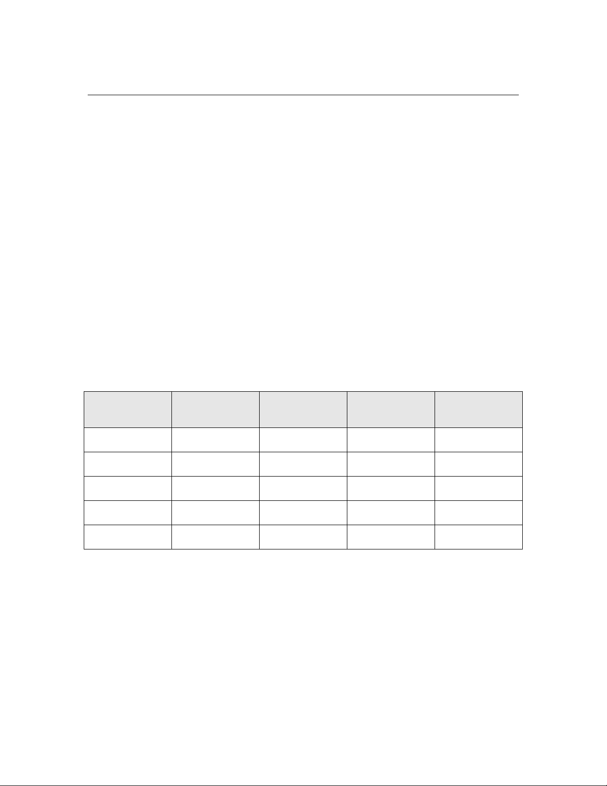
INC (Increment)
The INC instruction can increment the TOS value or the value of a specified
pointer register. The INC instruction uses the pointer direct addressing mode.
When incrementing TOS, if the TOS value is zero after the increment, this
instruction sets the Carry flag. When incrementing a pointer register, the
pointer-register expression must be in the range 0 to 3.
The INC instruction applies to Series 3100, 5000, and 6000 devices.
Syntax:
The INC instruction for the TOS requires no operands:
INC
The INC instruction for a pointer register requires a single operand to specify the
pointer register:
INC [0]
INC [1]
INC [2]
INC [3]
Table 32 describes the attributes of the INC instruction.
Table 32. INC Instruction
Instruction Hexadecimal
Opcode
INC 3E 1 2 Modified
INC [0] 34 1 6 None
INC [1] 35 1 6 None
INC [2] 36 1 6 None
INC [3] 37 1 6 None
Example:
The following example calls assumes that TOS contains a loop-control variable
with a negative value. The INC instruction increments TOS. When TOS
becomes zero and Carry flag is set, the BRC instruction branches to the Done
label. As long as the Carry flag is not set, the BR instruction branches to the
Loop label. Thus, this example implements a for loop construct.
Loop ... ; loop body
inc ; ( n )
brc Done
br Loop
Instruction
Size (Bytes)
CPU Cycles
Required
Affect on
Carry Flag
88 Neuron Assembly Language Instruction Statements
Page 99

Done ...
ret ; return to caller
Neuron Assembly Language Reference 89
Page 100

):(* TOSNEXTTOSNEXT ⇒
MUL (Multiply)
The MUL instruction performs integer multiplication. The MUL instruction
uses the implicit addressing mode. The instruction multiplies the unsigned
integer multiplicand value in NEXT with the unsigned integer multiplier value
in TOS. The 16-bit product result is placed in NEXT and TOS. Because the data
stack grows towards higher addresses, NEXT holds the most-significant byte
(MSB) and TOS holds the least-significant byte (LSB) of the 16-bit value. Thus,
this instruction implements the following equation:
where NEXT:TOS represents a 16-bit product.
Recommendation: Use the _mul16 or _mul16s system functions to multiply
unsigned or signed 16-bit numbers. See _mul16 (Multiply, 16 Bit); and _mul16s
(Multiply Signed, 16 Bit).
The MUL instruction applies to Series 5000 and 6000 devices.
Syntax:
The MUL instruction requires no operands:
MUL
Table 33 describes the attributes of the MUL instruction.
Table 33. MUL Instruction
Instruction Hexadecimal
Opcode
MUL EC 1 14 None
Example:
The following example performs the multiplication 18*68 (h’12 * h’44). Before
the MUL instruction executes, TOS contains 18 (h’12) and NEXT contains 68
(h’44). After the MUL instruction executes, TOS contains 200 (h’C8), which are
the low 8 bits of the product, and NEXT contains 4 (h’04), which are the high 8
bits of the product. Together, NEXT:TOS contain the 16-bit product, 1224
(h’04C8).
pushs #@LB(68) ; (h’44, -, -)
pushs #@LB(18) ; (h’12, h’44, -)
mul ; (h’C8, h’04, -)
Instruction
Size (Bytes)
CPU Cycles
Required
Affect on
Carry Flag
90 Neuron Assembly Language Instruction Statements
 Loading...