

Page 1

Mini FX User’s Guide
®
0 7 8 - 0 3 9 8 - 0 1 A
Page 2

Page 3

Echelon, LON, L
i.LON, LNS, LonMaker, L
ONWORKS, Neuron, 3120, 3150, Digital Home,
ONMARK, LonPoint, LonTalk,
NodeBuilder, ShortStack, and the Echelon logo are
trademarks of Echelon Corporation registered in the United
States and other countries. FTXL, LonScanner, LonSupport,
OpenLDV, and LNS Powered by Echelon are trademarks of
Echelon Corporation.
Other brand and product names are trademarks or
registered trademarks of their respective holders.
Neuron
Chips and other OEM Products were not designed for
use in equipment or systems which involve danger to human
health or safety or a risk of property damage and Echelon
assumes no responsibility or liability for use of the Neuron
Chips or LonPoint Modules in such applications.
Parts manufactured by vendors other than Echelon and
referenced in this document have been described for
illustrative purposes only, and may not have been tested by
Echelon. It is the responsibility of the customer to determine
the suitability of these parts for each application.
ECHELON MAKES NO REPRESENTATION, WARRANTY, OR
CONDITION OF ANY KIND, EXPRESS, IMPLIED, STATUTORY, OR
OTHERWISE OR IN ANY COMMUNICATION WITH YOU,
INCLUDING, BUT NOT LIMITED TO, ANY IMPLIED WARRANTIES OF
MERCHANTABILITY, SATISFACTORY QUALITY, FITNESS FOR ANY
PARTICULAR PURPOSE, NONINFRINGEMENT, AND THEIR
EQUIVALENTS.
No part of this publication may be reproduced, stored in a
retrieval system, or transmitted, in any form or by any means,
electronic, mechanical, photocopying, recording, or
otherwise, without the prior written permission of Echelon
Corporation.
Printed in the United States of America.
Copyright ©1997–2009 by Echelon
Corporation.
Echelon Corporation
www.echelon.com
ii
Page 4

Table of Contents
Preface..................................................................................................vii
Purpose ........................................................................................................viii
Audience ......................................................................................................viii
Hardware Requirements ............................................................................viii
Content ..........................................................................................................ix
Related Manuals ...........................................................................................ix
For More Information and Technical Support ............................................xi
1 Introduction .................................................................................... 1
Introduction to the Mini FX Evaluation Kit ................................................2
New Features in the Mini FX Evaluation Kit.............................................. 2
Series 5000 Chip Support .......................................................................2
Improved Memory Architecture ....................................................... 3
Faster System Clock .........................................................................4
Improved Performance for Arithmetic Operations ......................... 4
User-Programmable Interrupts ....................................................... 4
Additional I/O Model Support .......................................................... 5
Increased Network Variable Support .............................................. 5
Smaller Layout.................................................................................. 5
Backwards Compatibility for Device Applications ......................... 5
FT 5000 EVB Evaluation Board............................................................. 6
PL 3150 and 3170 EVB Evaluation Board............................................. 6
Neuron C Version 2.2 Enhancements .................................................... 7
Interrupt Support ............................................................................. 7
Non-Constant Device-Specific Configuration Property Support ... 7
New and Enhanced I/O Models........................................................ 7
New and Enhanced Compiler Directives......................................... 7
Hardware Template Editor..................................................................... 8
Microsoft Windows Vista Support .......................................................... 8
What's Included with the Mini FX Evaluation Kit...................................... 8
Mini FX CD .............................................................................................. 9
Development Platforms......................................................................... 10
FT 5000 EVB Evaluation Board ....................................................10
PL 3150 and PL 3170 EVB Evaluation Boards.............................10
LonScanner Protocol Analyzer CD (Demo Edition) ............................ 11
U10/U20 USB Network Interface......................................................... 12
Upgrading the Development Environment ................................................ 12
Upgrading to the NodeBuilder FX Tool ............................................... 12
Upgrading to the LonMaker Tool ......................................................... 14
Activating the LonScanner Tool ........................................................... 15
Introduction to Mini FX Device Development and LONWORKS
Networks.......................................................................................................
Channels ................................................................................................16
Routers ................................................................................................... 16
Applications ...........................................................................................17
Program IDs........................................................................................... 17
Network Variables................................................................................. 18
Configuration Properties....................................................................... 20
Functional Blocks .................................................................................. 20
Functional Profiles ................................................................................20
15
Mini FX User's Guide iii
Page 5

Hardware Templates.............................................................................
Neuron C ................................................................................................ 21
Device Templates................................................................................... 21
Device Interface Files............................................................................ 22
Resource Files ........................................................................................ 22
21
2 Installing the Mini FX Evaluation Kit..................................... 23
Installing the Mini FX Evaluation Kit .......................................................24
Installing the Mini FX Software........................................................... 24
Connecting the Mini FX Hardware ...................................................... 29
Connecting the Mini FX/FT Hardware.......................................... 30
Connecting the Mini FX/PL Hardware.......................................... 33
3 Mini FX Quick-Start Exercise ................................................... 37
Mini FX Quick-Start Exercise..................................................................... 38
Step 1: Creating the Device Application .............................................. 38
Step 2: Writing the Device Application................................................ 39
FT 5000 Evaluation Boards............................................................ 39
PL 3150 and PL 3170 Evaluation Boards .....................................41
Step 3: Building the Device Application .............................................. 42
Step 4: Downloading the Device Application ....................................... 45
Step 5: Testing the Device Application ................................................46
4 Using the Mini FX Application.................................................. 47
Introduction to the Mini FX Application .................................................... 48
Building a Device Application ..................................................................... 48
Creating and Opening Neuron C Source Files ....................................49
Selecting the Hardware Template........................................................ 51
Specifying the Program ID.................................................................... 51
Building the Application Image File .................................................... 55
Downloading an Application Image File ....................................................55
Resetting, Winking, and Testing Devices................................................... 60
5 Developing Device Applications............................................... 63
Introduction to Neuron C ............................................................................64
Unique Aspects of Neuron C................................................................. 64
Neuron C Variables ............................................................................... 66
Neuron C Variable Types ...............................................................66
Neuron C Storage Classes .............................................................. 67
Variable Initialization ....................................................................68
Neuron C Declarations ...................................................................68
Getting Started with Neuron C................................................................... 69
Performing Neuron C Input/Output..................................................... 70
Switches........................................................................................... 72
FT 5000 EVB............................................................................. 72
Mini Gizmo I/O Board .............................................................. 73
Conditional Compilation Example .......................................... 74
LEDs ................................................................................................75
FT 5000 EVB............................................................................. 76
Mini Gizmo I/O Board .............................................................. 76
Conditional Compilation Example .......................................... 76
Temperature Sensor .......................................................................77
Serial I/O.......................................................................................... 78
LCD Display .................................................................................... 79
iv Preface
Page 6

I/O Examples Toolkit ......................................................................
Creating Example Device Applications................................................ 84
Digital Sensor and Actuator Examples ......................................... 85
Simple Digital Sensor............................................................... 85
Simple Digital Actuator ...........................................................86
Advanced Digital Actuator....................................................... 86
Advanced Digital Sensor Example .......................................... 88
Thermostat Example ......................................................................89
ISI Example..................................................................................... 92
80
Appendix A Glossary ........................................................................ 97
Appendix B Creating and Editing Hardware Templates ...... 109
Using Hardware Templates ......................................................................110
Creating Custom Hardware Templates ............................................. 111
Configuring Hardware Templates...................................................... 111
Setting Hardware Properties .......................................................111
Setting Memory Properties ..........................................................114
Series 5000 Chips ................................................................... 115
3150 Neuron Core................................................................... 116
3170 Neuron Core................................................................... 116
Setting the Hardware Template Description .............................. 117
Appendix C Mini FX Software License Agreement................. 119
Mini FX User's Guide v
Page 7

vi Preface
Page 8

Preface
The Mini FX Development Kit is a hardware and software
platform for evaluating the L
developing simple L
build Neuron
ONWORKS devices, and test LONWORKS devices.
L
ONWORKS devices. The Mini kit lets you
®
C applications and download them to
ONWORKS
®
2.0 platform and
Mini FX User's Guide vii
Page 9

Purpose
This document describes how to use the Mini FX Evaluation Kit to develop and build
simple Neuron C device applications, download the device applications to L
devices, and test the L
ONWORKS devices.
ONWORKS
Audience
This guide is intended for device and system designers with an understanding of control
networks.
Hardware Requirements
Requirements for computers running the Mini kit are listed below:
• Microsoft
you install the latest service pack available from Microsoft for your version of
Windows.
• Intel® Pentium
requirements for the selected version of Windows.
®
Windows Vista® or Microsoft Windows® XP. Echelon recommends that
®
III 600MHz processor or faster, and meeting the minimum Windows
• 120 to 350 megabytes (MB) free hard-disk space, plus the minimum Windows
requirements for the selected version of Windows.
o The Mini kit requires 90 MB of free space.
o Microsoft .NET Framework 3.5 SP1, which is required to run the Mini FX
Application, requires 30 MB of free space.
o The LonScanner
Mini kit software, requires 26 MB of free space.
o If you install Adobe
an additional 204 MB of free space. You need Adobe Reader or another PDF
viewer to view the Mini kit documentation.
• 512 MB RAM minimum.
• Note: Windows Vista testing for the Mini FX Application has been performed on
computers that have a minimum of 2 GB of RAM. For complete Windows Vista
requirements, refer to
www.microsoft.com/windows/windows-vista/get/system-requirements.aspx. You
can use Microsoft’s Vista Upgrade Advisor to determine upgrade requirements for a
particular computer. To download this tool, go to the Microsoft Web site at
www.microsoft.com/windows/windows-vista/get/upgrade-advisor.aspx.
• CD-ROM drive.
• 1024x768 or higher-resolution display with at least 256 colors.
™
Protocol Analyzer (Demo Edition), which is included with the
®
Reader 9.1 from the Mini FX Evaluation Kit CD, you need
• Mouse or compatible pointing device.
• LNS
viii Preface
®
network interface or IP-852 router. If an LNS network interface is used, it
may be a local or remote interface.
o Compatible local network interfaces include the U10/U20 USB network interface
(included with the Mini FX/FT and Mini FX/PL Evaluation Kits); PCC-10,
Page 10

PCLTA-20, or PCLTA-21 network interfaces; and the SLTA-10 Serial LonTalk
Adapter.
o Compatible remote network interfaces include the i.LON® SmartServer, i.LON
100 e3 plus Internet Server, or i.LON 600 L
o Compatible IP-852 routers include the i.LON SmartServer with IP-852 routing,
i.LON 100 e3 plus Internet Server with IP-852 routing, or an i.LON 600
ONWORKS-IP Server. If you are using an IP-852 router, your computer must
L
have an IP network interface such as an Ethernet card or modem with PPP
software. In addition, the i.LON software must be installed on your computer,
and the IP-852 channel must be configured using the L
Configuration Server application software.
Content
This guide includes the following content:
•
Introduction: Lists the new features in the Mini FX Evaluation Kit, and summarizes
the components included with the Mini kit. Describes how to upgrade your device
development environment with the NodeBuilder tool, LonMaker tool, and an
activated LonScanner tool. It provides an overview of device development with the
Mini kit and L
ONWORKS networks.
ONWORKS-IP Server.
ONWORKS-IP
•
Installing the Mini FX Evaluation Kit. Describes how to get started with your Mini
FX, including how to install the Mini FX software and connect the Mini FX
hardware.
• Mini FX Quick-Start Exercise. Demonstrates how to create a device with the Mini
kit.
• Using the Mini FX Application. Describes how to use the Mini FX Application to
build a Neuron C application image, download an application image into a device,
and test a device.
Developing Device Applications. Introduces the Neuron C Version 2.2 programming
•
language, and provides a series of programming examples that demonstrate Neuron
C concepts, including input/output, timers, network variables, configuration
properties, functional blocks, and Interoperable Self-Installation (ISI).
• Appendices. Includes a glossary, an appendix describing how to create and edit
custom hardware templates, and the Mini Kit Software License agreement.
Related Manuals
The documentation related to the Mini kit is provided as Adobe PDF files and online help
files. The PDF files are installed in the Echelon Mini program folder when you install
the Mini kit. You can download the latest Mini FX documentation, including the latest
version of this guide, from Echelon’s Web site at
The following manuals provide supplemental information to the material in this guide.
You can download these documents from Echelon’s Web site at www.echelon.com.
www.echelon.com/docs.
FT 5000 EVB Examples Guide Describes how to run the Neuron C example
applications included with the Mini FX/FT Evaluation
Kit on an FT 5000 EVB.
Mini FX User's Guide ix
Page 11

FT 5000 EVB Hardware Guide Describes how to connect the FT 5000 EVBs, and
describes the Neuron core, I/O devices, service pin and
reset buttons and LEDs, and jumper settings on the FT
5000 EVB hardware.
Two FT 5000 EVBs are included with the Mini FX/FT
Evaluation Kit.
Introduction to the L
Platform
ONWORKS
Provides a high-level introduction to L
networks and the tools and components that are used
ONWORKS
®
for developing, installing, operating, and maintaining
them.
I/O Model Reference for Smart
Transceivers and Neuron Chips
Describes the many different I/O models that are
available for use with the Neuron Chips and Smart
Transceivers.
LonMaker
®
User’s Guide
Describes how to use the LonMaker Integration Tool to
design, commission, modify, and maintain L
networks.
ONMARK
L
Guide
®
SNVT and SCPT
Documents the standard network variable types
(SNVTs), standard configuration property types
(SCPTs), and standard enumeration types that you can
declare in your applications.
LonScanner™ Protocol Analyzer
User’s Guide
Describes how to use the LonScanner Protocol Analyzer
to monitor, analyze, and diagnose ISO/IEC 14908-4,
ONWORKS/IP, and native ISO/IEC 14908-1 channels,
L
and how to interpret the data that the protocol analyzer
collects.
ONWORKS
L
®
USB Network
Interface User’s Guide
Describes how to install and use the U10 and U20 USB
Network Interfaces, which are included with the Mini
FX/FT Evaluation Kit and Mini FX/PL Evaluation Kit,
respectively.
Mini FX/PL Examples Guide Describes how to run the Neuron C example
applications included with the Mini FX/PL Evaluation
Kit on PL 3150 and PL 3170 EVBs.
ONWORKS
Mini FX/PL Hardware Guide Describes how to connect the PL 3150 and PL 3170
EVBs, and describes the I/O devices, service pin and
reset buttons and LEDs, and jumper settings on the PL
3150 and PL 3170 EVBs, and Mini Gizmo I/O Boards.
The Mini FX/PL Evaluation Kit includes one PL 3150
EVB and one PL 3170 EVB.
Neuron
®
C Programmer’s Guide
Describes how to write programs using the Neuron
Version 2.2 language.
Neuron
®
C Reference Guide
Provides reference information for writing programs
using the Neuron C language.
Neuron
®
Tools Error Guide
Provides reference information for Neuron tool errors.
x Preface
C
Page 12

NodeBuilder
User’s Guide
®
Resource Editor
Describes how to use the NodeBuilder Resource Editor
to create and edit resource file sets and resources such
as functional profiles, network variable types, and
configuration property types.
®
PL 3120
/ PL 3150® / PL 3170
Smart Transceiver Data Book
™
Provides detailed technical specifications on the
electrical interfaces, mechanical interfaces, and
operating environment characteristics for the PL 3120,
PL 3150, and PL 3170 Power Line Smart Transceivers.
For More Information and Technical Support
The Mini FX ReadMe document provides descriptions of known problems, if any, and
their workarounds. To view the Mini FX ReadMe, click Start, point to Programs,
point to Echelon Mini, and then select Mini FX ReadMe First. You can also find
additional information about the Mini kit at the Mini FX Web page at
www.echelon.com/mini.
If you have technical questions that are not answered by this document, the Mini FX
online help, or the Mini FX ReadMe file, you can contact technical support. Free e-mail
support is available or you can purchase phone support from Echelon or an Echelon
support partner. See
support and training services.
You can also view free online training or enroll in training classes at Echelon or an
Echelon training center to learn more about developing devices. You can find additional
information about device development training at
www.echelon.com/support for more information on Echelon
www.echelon.com/training.
You can obtain technical support via phone, fax, or e-mail from your closest Echelon
support center. The contact information is as follows (check www.echelon.com/support
for updates to this information):
Region Languages Supported Contact Information
The Americas
English
Japanese
Echelon Corporation
Attn. Customer Support
550 Meridian Avenue
San Jose, CA 95126
Phone (toll-free):
1.800-258-4LON (258-4566)
Phone: +1.408-938-5200
Fax: +1.408-790-3801
lonsupport@echelon.com
Europe
English
German
French
Italian
Echelon Europe Ltd.
Suite 12
Building 6
Croxley Green Business
Park
Hatters Lane
Watford
Hertfordshire WD18 8YH
United Kingdom
Phone: +44 (0)1923 430200
Fax: +44 (0)1923 430300
lonsupport@echelon.co.uk
Mini FX User's Guide xi
Page 13

Region Languages Supported Contact Information
Japan
Japanese Echelon Japan
Holland Hills Mori Tower,
18F
5-11.2 Toranomon,
Minato-ku
Tokyo 105-0001
Japan
Phone: +81.3-5733-3320
Fax: +81.3-5733-3321
lonsupport@echelon.co.jp
China
Other Regions
Chinese
English
English
Japanese
Echelon Greater China
Rm. 1007-1008, IBM Tower
Pacific Century Place
2A Gong Ti Bei Lu
Chaoyang District
Beijing 100027, China
Phone: +86-10-6539-3750
Fax: +86-10-6539-3754
lonsupport@echelon.com.cn
Phone: +1.408-938-5200
Fax: +1.408-328-3801
lonsupport@echelon.com
xii Preface
Page 14

1
Introduction
This chapter introduces the Mini FX Evaluation Kit. It lists
the new features in the Mini kit, and it summarizes the
components included with the Mini kit. It describes how to
upgrade your device development environment with the
NodeBuilder tool, LonMaker tool, and an activated
LonScanner tool. It provides an overview of device
development with the Mini kit and L
ONWORKS networks.
Mini FX User's Guide 1
Page 15

Introduction to the Mini FX Evaluation Kit
The Mini FX Evaluation Kit is a hardware and software platform for evaluating the
L
ONWORKS
and 3100 Neuron Chips and Smart Transceivers. The Mini kit lets you build Neuron C
applications and download them to L
You can use the Mini kit to develop prototype or production devices, particularly in the
rapidly growing, price-sensitive mass markets of smart light switches, thermostats, and
other simple devices and sensors.
You can use the Mini kit to do the following:
• Compile, build, and download a Neuron C device application to a development
platform or to your own devices.
• Test with prototype I/O hardware on either the FT 5000 EVBs included with the
Mini FX/FT Evaluation Kit and available separately, or with the PL 3150 and PL
3170 EVBs included with the Mini FX/PL Evaluation Kit and available separately, or
build and test your own I/O hardware with your own custom device.
• Create a self-installed L
with other L
LonMaker
• View standard resource file definitions for standard network variable types (SNVTs),
standard configuration property (SCPTs), and standard functional profiles.
• Create your own resource files with user-defined network variable types (UNVTs),
user-defined configuration property (UCPTs), and user-defined functional profiles.
®
2.0 platform and developing LONWORKS devices based on the Series 5000
ONWORKS devices, and test LONWORKS devices.
ONWORKS network and test how your device interoperates
ONWORKS devices—or use the Mini kit with a separately purchased
®
Integration Tool to create a managed LONWORKS network.
New Features in the Mini FX Evaluation Kit
The Mini FX Evaluation Kit adds support for Echelon’s new Series 5000 chips (the term
used to collectively refer to the Neuron 5000 Processor and FT 5000 Smart Transceiver),
support for Echelon’s new FT 5000 EVB and new PL 3170 EVB, and the following key
features:
• Neuron C Version 2.2 Enhancements
• Hardware Template Editor
• Microsoft Windows Vista support
Series 5000 Chip Support
The Mini FX Evaluation Kit supports Echelon’s new Neuron 5000 Processor and FT 5000
Smart Transceiver, which are designed for the L
chips are faster, smaller, and cheaper that previous-generation chips, as they include the
following new features and functions.
• Improved memory architecture.
• Faster system clock.
• Improved performance for arithmetic operations.
• User-programmable interrupts.
• Additional I/O model support.
• Increased network variable support (NodeBuilder tool required).
• Smaller layout
ONWORKS 2.0 platform. The Series 5000
2 Introduction
Page 16

• Backwards compatibility for device applications.
Improved Memory Architecture
The Series 5000 chips have a new memory architecture that speeds up the CPU
operation and lowers development and device costs. The Series 5000 chips have internal
on-chip memory that includes 16 KB of ROM to store the Neuron firmware image and 64
KB of RAM (44 KB is available for application code and data). The Series 5000 chips use
external serial memory (EEPROM or flash) to store your application code, configuration
data, and an upgradable Neuron firmware image (the Series 5000 chips have no
user-accessible on-chip non-volatile memory). The external serial EEPROM and flash
memory devices communicate with Neuron 5000 Core via a serial peripheral interface
bus (SPI) or Inter-Integrated Circuit (I
2
SPI or I
C interfaces; flash devices must use the SPI interface.
When a device is reset, the application code and configuration data are copied from the
external non-volatile memory into the internal on-chip RAM, and the device application
is then executed. The Series 5000 chips require at least 2KB of off-chip EEPROM to
store configuration data, and you can use a larger capacity EEPROM device or an
additional flash device (up to 64 KB) to store your application code and an upgradable
Neuron firmware image.
The Series 5000 chips also include a new interrupt processor that handles
user-programmable interrupts, which improves chip performance.
2
C) interface. EEPROM devices can use either the
Note: Many types of EEPROM devices are supported; however, Echelon currently
supports and provides drivers for three external flash devices: Atmel AT25F512AN,
STM25P05, and SST25VF512A. You can configure the external non-volatile memory
used by a device in the Hardware Template Editor. For more information on using the
Hardware Template Editor, see Chapter 3.
Figure 1.1 illustrates the architecture of the Series 5000 chips. For more information on
the memory architecture of the Series 5000 chips, see the Series 5000 Chip Data Book.
Mini FX User's Guide 3
Page 17
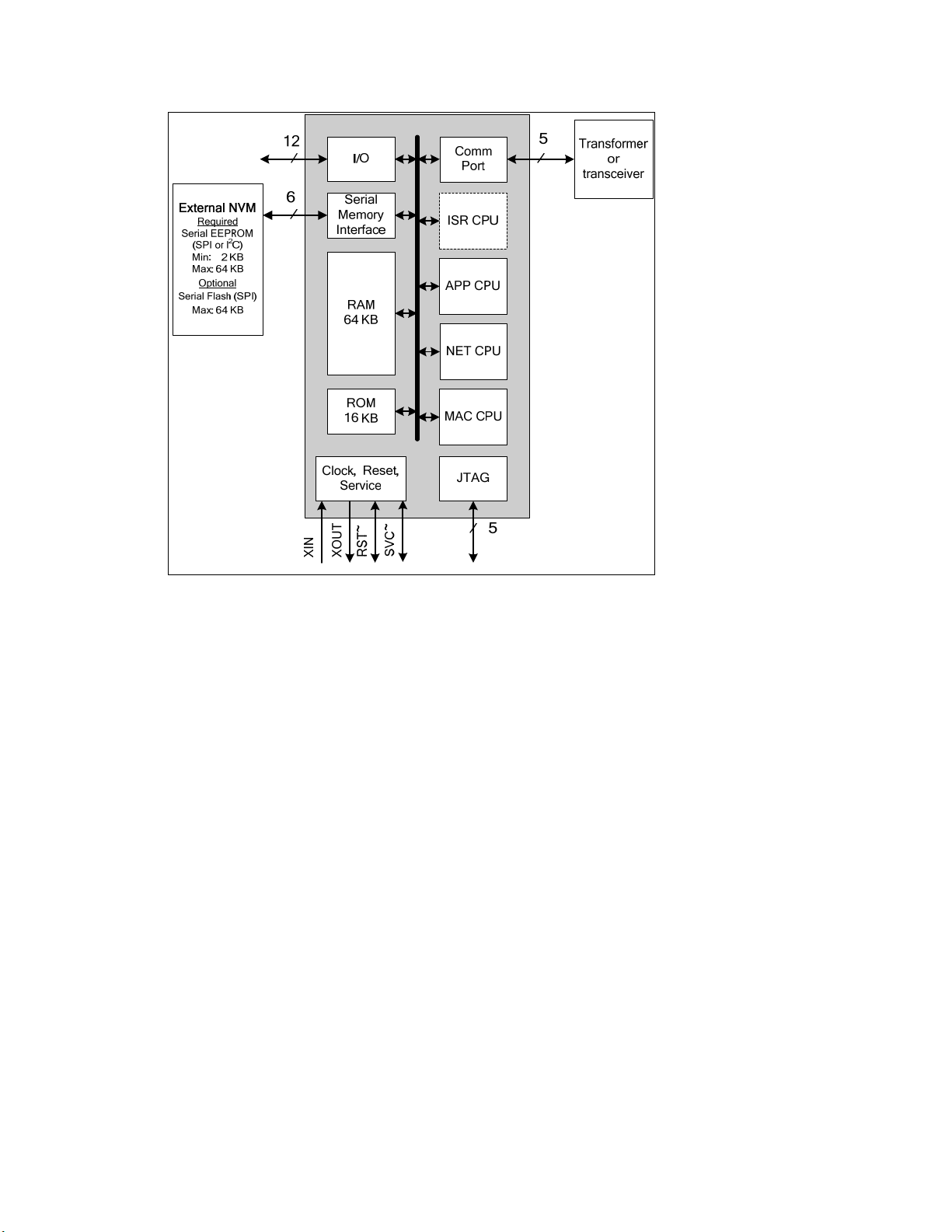
Figure 1.1 Series 5000 Chip Architecture
Faster System Clock
The Series 5000 chips support an internal system clock speed of up to 80 MHz (using an
external 10 MHz crystal). This results in application processing power that equals a
hypothetical FT 3150 Smart Transceiver operating at an external clock speed of 160MHz.
You can adjust the internal system clock speed from 5 MHz to 80 MHz through the
device’s hardware template. For more information on configuring the system clock of the
Series 5000 chips, see
Appendix B, Creating and Editing Hardware Templates.
Improved Performance for Arithmetic Operations
The Series 5000 chips include 8-bit hardware multipliers and dividers, which are
supported by new Neuron assembly language instructions for multiplication and division.
These instructions use hardware multiply and divide functions to provide improved
performance for 8-bit multiplication and division. The older software multiplication and
division system functions are still supported, but many of these functions automatically
benefit from these faster hardware multipliers and dividers.
User-Programmable Interrupts
The Series 5000 chips let you define user interrupts that can handle asynchronous I/O
events, timer/counter events, and a dedicated, high-resolution system timer. A hardware
semaphore is supplied to help you control access to data that is shared between the
application (APP) and interrupt (ISR) processors on the Series 5000 chips.
At higher system clock rates (20 MHz or greater), these interrupts run in the dedicated
interrupt processor (ISR) on the chip. This improves the performance of the interrupt
4 Introduction
Page 18

routines and your device application. At lower system clock rates, these interrupts run
in the same application processor (APP) as the device application.
Additional I/O Model Support
The Series 5000 chips include hardware support for the Serial Peripheral Interface (SPI)
and Serial Communication Interface (SCI) serial I/O models, which provide increased
performance for devices that use these interfaces. The UART on the Series 5000 chips
includes an increased FIFO (16 bytes), and supports software-configurable parity
generation and validation (odd, even, none) for the SCI model.
Overall, the Series 5000 chips support 35 I/O models, including all of the I/O models that
were previously only supported by the PL 3120, PL 3150, and PL 3170 Smart
Transceivers. These I/O models include the new Infrared Pattern, Magcard Bitstream,
SCI, and SPI models.
In addition, the Series 5000 chips support the Stretched Triac model, which is a new I/O
model that improves performance for triac devices used with reactive loads.
Increased Network Variable Support
The Series 5000 chips can support up to 254 static network variables and 127 network
variable aliases, subject to available system resources (for example, RAM and EEPROM)
and application requirements. All current Series 3100 chips with Neuron firmware
version 16 or better also support these increased network variable limits, subject to
available memory resources.
You must build the application with the NodeBuilder FX tool to take advantage of these
increased network variable limits. If you use the Mini FX Application, your device
application is limited to 32 network variables.
Smaller Layout
The Series 5000 chips feature a more compact design using a 7 mm by 7 mm 48-pin quad
flat no leads (QFN) packaging and 3.3V operation (I/O pins are 5V-tolerant)
Backwards Compatibility for Device Applications
The Series 5000 chips are compatible with device applications written for 3150 and 3120
Neuron Chips and Smart Transceivers. You can use the Mini kit to port your Series
3100 application to a Series 5000 chip. To do this, you open the Mini kit application and
verify that the existing application can be built using Mini FX Application. If the build is
successful, create a hardware template for your device based on the Series 5000 chip, and
then re-build the device application using the new hardware template. See
Hardware Template in Chapter 4 and,
Templates See in Chapter 4 for more information on using the Hardware Template
Editor.
Notes:
The Neuron firmware contains the implementation of the ISO/IEC 14908-1 protocol
stack, the application scheduler, and many frequently used functions. The functions
included in the Neuron firmware vary between firmware versions and chip models;
therefore, when you rebuild an existing application for a FT 5000 Smart Transceiver, the
application may have a smaller or larger memory footprint, subject to the application’s
use of library functions.
Appendix B, Creating and Editing Hardware
Selecting the
Mini FX User's Guide 5
Page 19

The Neuron C Version 2.2 language includes new keywords such as interrupt, __lock,
stretchedtriac, __slow, __fast, and __parity. Some of these keywords use a double
underscore prefix to avoid any likely naming collisions within existing device
applications.
FT 5000 EVB Evaluation Board
The FT 5000 EVB is a complete Series 5000 LONWORKS device that you can use to
evaluate the L
includes a FT 5000 Smart Transceiver with an external 10 MHz crystal (you can adjust
the system’s internal clock speed from 5MHz to 80MHz), an FT-X3 communication
transformer, 64KB external serial EEPROM and flash memory devices, and a 3.3V power
source. The FT 5000 EVB features a compact design that includes the following I/O
devices that you can use to develop prototype and production devices and test the FT
5000 EVB example applications:
• 4 x 20 character LCD
• 4-way joystick with center push button
• 2 push-button inputs
• 2 LED outputs
• Light-level sensor
• Temperature sensor
ONWORKS 2.0 platform and create LONWORKS devices. The FT 5000 EVB
The FT 5000 EVB Evaluation Board also includes EIA-232/TIA-232 (formerly RS-232)
and USB interfaces that you can use to connect the board to your development computer
and perform application-level debugging. You can also use the EIA-232 interface or
other interfaces provided for development with the ShortStack® Developer’s Kit. Note
that only one interface can be used at a time.
Note: You must use the ShortStack FX Developer’s Kit to develop ShortStack
applications for the FT 5000 EVB. Earlier versions of the kit do not support the FT 5000
EVB.
The FT 5000 EVB supports the in-circuit programming of the external serial EEPROM
and flash devices used by the FT 5000 Smart Transceiver on the FT 5000 EVB. This
provides an alternative to loading application images into these external serial memory
devices over the TP/FT-10 network.
The FT 5000 EVB also features a flash in-circuit emulator (ICE) header that you can use
to connect an SPI flash ICE. This provides an alternative to using the external serial
non-volatile memory flash device on the FT 5000 EVB.
For more information on the FT 5000 EVB hardware, including detailed descriptions of
its Neuron core, I/O devices, service pin and reset buttons and LEDs, jumper settings,
and in-circuit programming instructions, see the FT 5000 EVB Hardware Guide.
PL 3150 and 3170 EVB Evaluation Board
The PL 3170 EVB is a complete LONWORKS device that you can use to evaluate the
ONWORKS 2.0 platform and create simple LONWORKS devices. The PL 3170 EVB
L
includes a PL 3170 Smart Transceiver, which includes Interoperable Self Installation
(ISI) functions built into the firmware that is stored in the on-chip ROM. This lets you
create Neuron C device application that have a maximum of 4 KB code—even when
using ISI functions in the application.
6 Introduction
Page 20

The PL 3150 EVB is a complete L
Transceiver operating at 10MHz external clock (5MHz system clock speed), 64KB of
off-chip flash memory, and 2KB of on-chip RAM.
You can attach a Mini Gizmo I/O Board to the PL 3150/PL 3170 EVBs to test your device
applications and test the example applications included with the Mini FX/PL Evaluation
Kit.
ONWORKS device that includes a PL 3150 Smart
Neuron C Version 2.2 Enhancements
The new features in the Neuron C Version 2.2 programming language include interrupt
support, non-constant device-specific configuration properties, new and enhanced I/O
models, and new and enhanced compiler directives. These new features are detailed in
the Neuron C Programmer’s Guide and Neuron C Reference Guide.
Interrupt Support
The Series 5000 chips support hardware user interrupts in addition to the support
provided through I/O models. The Neuron C Version 2.2 language includes new
keywords to manage hardware user interrupts and a semaphore for application
programs. The Series 5000 chips support the following three types of interrupts: I/O
interrupts, timer/counter driven interrupts, and periodic system interrupts.
When the Series 5000 chips are running at a system clock rate of 20 MHz or greater,
these interrupts execute in the separate interrupt processor on the chips, which improves
the performance of the interrupt and the device application.
Non-Constant Device-Specific Configuration Property
Support
The Neuron C Version 2.2 language supports non-constant device-specific configuration
properties. Non-constant device-specific configuration properties have values that can be
modified by the device application, an LNS network tool such as the LonMaker
Integration Tool, or another tool not based on LNS. For example, a thermostat may
include a user interface that allows the user to change the setpoint.
®
New and Enhanced I/O Models
The Neuron C Version 2.2 language now includes support for the stretched triac output
model, and it includes some enhancements to the existing SCI and I2C I/O models.
The stretched triac output model provides improved control when driving inductive
loads. The stretched triac model requires a Neuron 5000 Processor.
The SCI input/output model now supports a configurable parity bit (none, even, odd).
The parity feature requires a Series 5000 chip even though the SCI model is available on
some Series 3100 chips.
The I2C input/output model now supports slow and fast operation speeds for compliance
with the I2C standard when operating at very high system clock speeds.
New and Enhanced Compiler Directives
The Neuron C Version 2.2 language includes new compiler directives and existing
compiler directives that have been enhanced to help you develop location-independent
and modular code.
Mini FX User's Guide 7
Page 21

You can enable and disable specific warnings using the new #pragma enable_warning
and #pragma disable_warning compiler directives, and you can use the new #error
and #warning compiler directives to manage conditional compilation, raising
user-defined warning or error messages as necessary. You can use the new #pragma
library directive to indicate any required library. You can use enhanced buffer control
directives for statements of minimum or final requirements.
Compiler directives for control of the Neuron C Optimizer have been streamlined, and a
new optimization phase for generating more compact code has been added.
Hardware Template Editor
The Mini kit now includes a Hardware Template Editor that you can use to create and
configure new custom hardware templates and edit existing ones. The Hardware
Template Editor can be launched from the Mini FX application, and it is available as a
standalone tool.
A hardware template is a file with a .NbHwt extension that defines the hardware
configuration for a target device. It specifies hardware attributes including platform,
transceiver type, Neuron Chip or Smart Transceiver model, clock speed, system image,
and memory configuration. Several standard hardware templates are included with the
Mini kit. You can use these or create your own.
The Hardware Template Editor supports hardware templates based on any supported
Neuron chip, including Series 5000 and Series 3100 chips. You use the Hardware
Template Editor to map external non-volatile memory from 0x4000 to 0xE7FF in the
Neuron address space (a maximum of 42 KB).
For more information on using the Hardware Template Editor, see
Hardware Template in Chapter 4 and,
Templates.
Appendix B, Creating and Editing Hardware
Selecting the
Microsoft Windows Vista Support
The Mini FX Application and online help files are compatible with Microsoft Windows
Vista.
What's Included with the Mini FX Evaluation Kit
There are two Mini FX products: the Mini FX/FT Evaluation Kit and the Mini FX/PL
Evaluation Kit. Table 1.1 lists the components included with the two Mini FX products:
Table 1.1 Mini FX Products
Mini FX CD
Component
Mini FX/FT
Evaluation
Kit
5 5
Mini FX/PL
Evaluation
Kit
Development Platforms
FT 5000 EVB Evaluation Boards
PL 3150 EVB and PL 3170 EVB Evaluation Boards
(1 each)
8 Introduction
5
5
Page 22

LonScanner Protocol Analyzer CD (Demo Edition)
U10 or U20 USB Network Interface
The following sections describe each of the components.
5 5
5 5
Mini FX CD
The Mini FX CD contains the software required to build and download Neuron C
applications for your L
that you can run on your development platform and use to further learn how to develop
your own device applications.
The Mini FX software includes the following programs:
• Mini FX Application. Manage Neuron C code, build Neuron C device applications,
and download the device applications to your development boards. The Mini FX
Application includes the following components:
o Hardware Template Editor. Specify hardware attributes including platform,
transceiver type, Neuron Chip or Smart Transceiver model, clock speed, system
image, and memory configuration.
o Standard Program ID Calculator. Specify the device’s 16-hex digit program ID,
which uniquely identifies the device application.
o Diagnostic Tool. Reset the device application, wink a device, or get the current
device status and statistics related to the device’s performance.
ONWORKS devices, and it includes Neuron C example applications
• NodeBuilder Resource Editor. Provides a simple interface for viewing existing
ONMARK® resources and defining your own resources. For more information on the
L
NodeBuilder Resource Editor, see the NodeBuilder Resource Editor User’s Guide.
• ISI Developer’s Kit. Provides for easy development of devices that do not require
installation tools. Consult the ISI Programmer’s Guide for more information on ISI.
™
• OpenLDV
messages through Echelon’s family of L
Mini FX Application and the Monitoring & Control C# example application that you
can download from the Echelon Web site uses the OpenLDV API. For more
information on OpenLDV, see the OpenLDV Programmer’s Guide. You can download
the OpenLDV Programmer’s Guide and the OpenLDV Developer’s Kit from the
Echelon Web site at
• Example Applications. The Mini kit include three Neuron C example applications
for the FT 5000 EVBs, and four Neuron C example applications for the PL 3150 EVB
and PL 3170 EVB. You can use these examples to test the I/O devices on your EVBs,
and create simple L
example applications, and then create a new device application by modifying the
existing example applications or by developing the device application from scratch.
For more information on using the FT 5000 EVB example applications, see the FT
5000 EVB Examples Guide. For more information on using the PL 3150 and PL 3170
example applications, see the Mini FX/PL Examples Guide.
Note: Mini FX/PL users can download a Monitoring & Control C# example
application from the Echelon Web site. This application monitors ISI messages and
uses the OpenLDV API to monitor and control network variables on devices,
including the PL 3150 and PL 3170 EVBs, running the MGDemo example.
3.4. An API used by the Mini kit to send and receive ISO/IEC 14908-1
ONWORKS network interface products. The
www.echelon.com/openldv.
ONWORKS networks. You can view the Neuron C code used in the
Mini FX User's Guide 9
Page 23
Development Platforms
The Mini FX/FT Evaluation Kit includes two FT 5000 EVBs. The Mini FX/PL
Evaluation Kit includes one PL 3150 EVB and one PL 3170 EVB. The following sections
describe these development platforms.
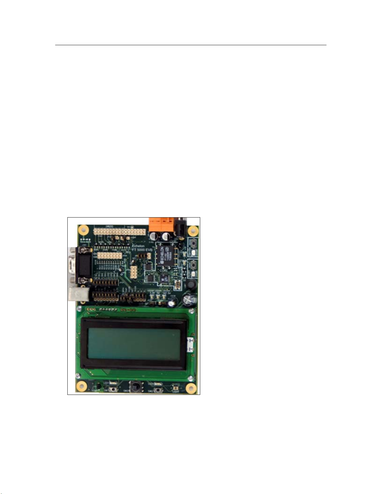
FT 5000 EVB Evaluation Board
The FT 5000 EVB is a complete Series 5000 LONWORKS device that you can use to
evaluate the L
includes an FT 5000 Smart Transceiver with an external 10 MHz crystal (you can adjust
the system’s internal clock speed from 5MHz to 80MHz), an FT-X3 communication
transformer, 64KB external serial EEPROM and flash memory devices, and a 3.3V power
source. The FT 5000 EVB features a compact design that includes the following I/O
devices that you can use to develop prototype and production devices and test the FT
5000 EVB example applications:
• 4 x 20 character LCD
• 4-way joystick with center push button
• 2 push-button inputs
• 2 LED outputs
• Light-level sensor
• Temperature sensor
ONWORKS 2.0 platform and create LONWORKS devices. The FT 5000 EVB
Figure 1.2 FT 5000 EVB
PL 3150 and PL 3170 EVB Evaluation Boards
The Mini FX/PL Evaluation Kit includes one PL 3150 EVB and one PL 3170 EVB. The
PL 3150 and 3170 EVBs utilize Echelon’s Power Line Smart Transceivers to signal over
any AC or DC power circuit, eliminating any need for additional wiring. The power
10 Introduction
Page 24
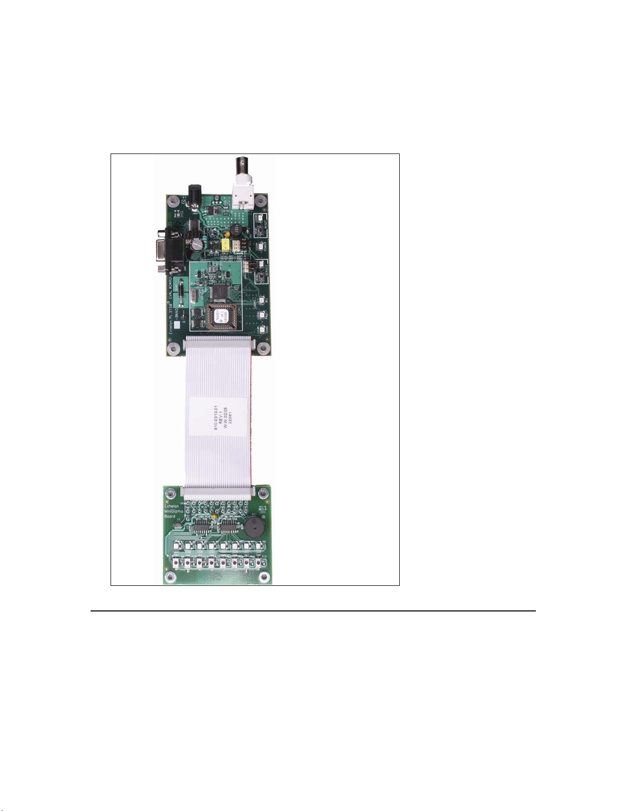
supplies included with the PL 3150 and 3170 EVBs pass the network signals directly into
the AC power lines over the same two wires that power the evaluation boards. With the
PL 3150 and 3170 EVBs, you can begin building a power line control network by simply
plugging the evaluation boards into an electrical outlet. You can also attach the included
Mini Gizmo I/O Boards to the PL 3150/PL 3170 EVBs to test your device applications and
run the example applications included with the Mini FX/PL Evaluation Kit.
Figure 1.3 PL 3150/PL 3170 EVB (top) and Mini Gizmo I/O Board (bottom)
LonScanner Protocol Analyzer CD (Demo Edition)
The LonScanner Protocol Analyzer is a software package that provides network
diagnostic tools to observe, analyze, and diagnose the behavior of installed L
networks, including network with devices that you have built with the Mini kit. A demo
version of the LonScanner Protocol Analyzer is included with your Mini kit. It is not
required to use the Mini kit, but the protocol analyzer will make your development and
integration efforts more productive. You can use the LonScanner tool with the U10 or
U20 USB network interface included with the Mini FX/FT and Mini FX/PL kits, and you
Mini FX User's Guide 11
ONWORKS
Page 25

also use it with other network interfaces including an IP-852 (ISO/IEC 14908-4) interface
as described in the LonScanner Protocol Analyzer User’s Guide.
The LonScanner tool included with the Mini kit will run in demo mode until you
purchase a key and activate it. When operating in demo mode, the protocol analyzer
does not display every captured packet and displays only the first 20 packets of a saved
or imported log file. In addition, the LonScanner License Activation dialog will appear
every time you open the protocol analyzer, and give you the option to activate your
LonScanner software. For more information on the LonScanner tool, including how to
purchase a key activate the software, see the LonScanner Protocol Analyzer User’s Guide.
U10/U20 USB Network Interface
The Mini FX/FT Evaluation Kit and Mini FX/PL Evaluation Kit include U10 and U20
USB network interfaces, respectively. The U10 and U20 USB Network Interfaces are
low-cost, high-performance L
controllers.
The U10 USB Network Interface connects directly to a TP/FT-10 Free Topology Twisted
Pair (ISO/IEC 14908-2) L
The U20 USB Network Interface connects to a PL-20 C-Band Power Line (ISO/IEC
14908-3) LONWORKS channel through an included power supply with integrated coupler.
The U20 USB Network Interface can also be connected directly to 10.8-18VDC power
systems (such as those in automobiles, trucks and buses) without a coupling circuit, or to
virtually any powered line through a customer-supplied coupler/power supply.
ONWORKS interfaces for USB-enabled computers and
ONWORKS channel through a high-quality removable connector.
The USB Network Interfaces can be used with virtually any computer-based L
application, including all LNS and OpenLDV based applications such as the Mini kit,
NodeBuilder
USB Network Interfaces are automatically installed when you install the Mini FX
software.
For more information on installing and using the U10 and U20 USB network interfaces,
see the L
tool, LonMaker tool, and LonScanner tool. Drivers for the U10 and U20
ONWORKS USB Network Interface User’s Guide.
ONWORKS
Upgrading the Development Environment
You can upgrade your device development environment with the NodeBuilder FX
Development Tool or the LonMaker tool, or by activating the LonScanner tool included
with your Mini kit. The following sections describe the features provided by each tool,
and how they can improve your device development projects.
Upgrading to the NodeBuilder FX Tool
You can upgrade your Mini kit to the NodeBuilder FX Development Tool to build larger
device applications and build them faster in an integrated development environment
with a source-level debugger. The NodeBuilder FX Development Tool also provides free
activation of the included LonMaker and LonScanner tools. The NodeBuilder tool
includes the following components to help speed up your device development projects:
• Code Wizard. Use a drag-and-drop interface to create your device’s interface and
then automatically generate Neuron C source code that implements the device
interface and creates the framework for your device application.
• Code Editor. Edit the Neuron C source code generated by the Code Wizard to create
your device’s application.
12 Introduction
Page 26

• Debugger. Debug your application with a source-level view of your application code
as it executes. The debugger lets you control and observe the behavior of your device
application over a L
monitor network variables, halt the application, step through the application, view
the call stack, and peek and poke memory. You can make changes to the code as you
debug a single device or debug multiple devices simultaneously.
• Project Manager. Build and download your application image to your development
platform or to your own device hardware.
®
• LonMaker
in your project using an LNS based application that combines a powerful,
client-server architecture with an easy-to-use Visio user interface. For more
information, see the LonMaker User’s Guide.
Activation of the LonMaker tool included with the NodeBuilder FX Development Tool
is free.
• LonScanner Protocol Analyzer (LNS Turbo Edition). Observe, analyze, and diagnose
the behavior of installed L
you have built with the Mini kit or NodeBuilder tool. For more information, see the
LonScanner Protocol Analyzer User’s Guide
Activation of the LonScanner tool included with the NodeBuilder FX Development
Tool is free.
Integration Tool. Install, connect, configure, test, and update the devices
ONWORKS channel. The debugger lets you set breakpoints,
ONWORKS networks, including network with devices that
• LNS Plug-in Framework Developer’s Kit. Write LNS device plug-ins in .NET
programming languages such as C# and Visual Basic .NET and re-distribute them.
For more information, see the LNS®Plug-in Programmer’s Guide.
Table 1.2 compares the Mini kit to the NodeBuilder FX tool.
Table 1.2 Comparison of the Mini Kit to the NodeBuilder Tool
Feature
Neuron C Compiler
Network Variables per Device
(maximum number)
Network Variables Aliases per Device
(maximum number)
Application Code and Constant Data per
Device (maximum size in KB)
Integrated Development Environment
Code Wizard
Code Editor
Mini FX
Evaluation Kit
5 5
32 254
32 127
32 44
5
5
5
NodeBuilder
FX Tool
a
a
Debugger
Project Manager
LonMaker Tool
Mini FX User's Guide 13
5
5
5
Page 27

Mini FX
Feature
LonScanner Protocol Analyzer (Demo
Edition)
LonScanner Protocol Analyzer (LNS Turbo
Edition)
LNS Plug-in Framework Kit
a
The NodeBuilder FX tool supports up to 254 static network variables and 127 network variable
aliases for Neuron-hosted devices that use version 16 firmware or greater (for example, the Series
5000 chips, which use version 18 firmware). This limit is subject to available system resources (for
example, RAM and EEPROM) and application requirements.
When you upgrade to the NodeBuilder tool, you can use your existing development
hardware, and you can incorporate the Neuron C source files, library files, and hardware
templates you developed with the Mini kit into your NodeBuilder projects.
Note: The Mini kit build process requires the automatic creation of NodeBuilder device
template files. The Mini kit uses the name of the Neuron C source file as the name of the
device template file. For example, compiling the myDeviceApplication.nc source file
with the Mini FX Application leads to the creation of a hidden
myDeviceApplication.nbdt device template file.
To use the same device template file for both the Mini and NodeBuilder build processes,
specify different names for the source file and the device template when you build the
source file with NodeBuilder tool. Possible conflicts resulting from the sharing of the
same NodeBuilder device template file can be resolved by viewing and editing the device
template preferences in the NodeBuilder tool.
Evaluation Kit
5
5
5
NodeBuilder
FX Tool
For more information on the NodeBuilder tool, see the NodeBuilder Web page at
www.echelon.com/nodebuilder. For more information on ordering the NodeBuilder tool,
contact your Echelon sales representative.
Upgrading to the LonMaker Tool
You can use the Mini kit to create self-installed devices, which do not require a network
management tool such as the LonMaker tool. The Mini kit supports standalone
applications (which may not require any network management), and self-installed
applications using the ISI protocol.
For more complex networks and applications that do require a network management
tool, you can use the LonMaker tool to install your development devices in a network,
and then configure, monitor, and test those devices. The LonMaker tool includes the
following features that you can use to test the Neuron C device applications you have
developed with the Mini kit: the LonMaker Browser, Data Point shapes, the LonMaker
Device Manager, and connection monitoring.
The LonMaker Browser is a standalone application that monitors all the network
outputs from your device and allows you to control all the network inputs to your
device. You can open the LonMaker Browser on any device or functional block in the
network. The LonMaker Browser displays all the network variables and
configuration properties for the selected network variables and configuration
properties. You can change the value of any of the input network variables or
writeable configuration properties.
14 Introduction
Page 28

The Data Point shape provides similar functionally as the LonMaker Browser, but
directly in your LonMaker drawing. The Data Point shape is a LonMaker Basic Shape
that you can add to your LonMaker drawing to monitor and control individual network
variables and configuration properties in your device. You can use a Data Point shape to
monitor the value of any input or output network variable, configuration property, or
functional block state (enabled or in override). You can also use a Data Point shape to
control the value of an input network variable or a configuration property. You can also
use Data Point shapes to create simple human-machine interface (HMI) applications for
your development devices within your LonMaker drawing.
The LonMaker Device Manager allows you to control the state of your device and its
functional blocks. You can use the device manager to reset your device, put your
device online or offline, and test network communication with your device. You can
also use the Device Manager to enable or disable individual functional blocks on your
device, and to invoke the self-test function of any of your functional blocks that
support self-test.
The LonMaker tool allows you to connect the network variables in your devices, and
then monitor those connections on the same page that you created the connections.
You can use monitored connections to view the values of network variables on your
LonMaker drawing. This feature is useful for monitoring and debugging your device
because monitored connections provide an easy way to visualize the flow of data
through your functional blocks.
Note: You cannot simultaneously use the same network interface with both the
LonMaker tool and the Mini FX Application. The Mini FX Application is an
OpenLDV application; therefore, it cannot share a network interface with other
ONWORKS applications. This means that when the Mini FX Application is attached
L
to a network interface, network tools such as the LonMaker tool cannot use that
network interface at the same time, and vice versa. To avoid network interface
conflicts, you can use the LonMaker tool to download and test device applications
that you have compiled with the Mini FX Application, or you can use separate
network interfaces for the LonMaker tool and the Mini FX Application.
Activating the LonScanner Tool
You can purchase a key to activate the LonScanner tool that is included with your Mini
kit. Once you activate your LonScanner tool, you can view every captured packet
transmitted and received by you development device and view all entries in saved or
imported log files.
Introduction to Mini FX Device Development and LONWORKS Networks
A LONWORKS network consists of intelligent devices (such as sensors, actuators, and
controllers) that communicate with each other using a common protocol over one or more
communications channels. Network devices are sometimes called nodes.
Devices may be Neuron hosted or host-based. Neuron hosted devices run a compiled
Neuron C application on a Neuron Chip or Smart Transceiver. You can use the Mini kit
to develop, test, and debug Neuron C applications for Neuron hosted devices.
Host-based devices run applications on a processor other than a Neuron Chip or Smart
Transceiver. Host-based devices may run applications written in any language available
to the processor. A host-based device may use a Neuron Chip or Smart Transceiver as a
Mini FX User's Guide 15
Page 29

communications processor, or it may handle both application processing and
communications processing on the host processor. The Mini kit supports some of the
common tasks occurring in the creation of host-based devices; however, an additional
host-based device development tool, such as the ShortStack® FX or the FTXL™
Developer’s Kit combined with a host development tool, is required.
Each device includes one or more processors that implement the ISO/IEC
Control Network Protocol (CNP). Each device also includes a transceiver to provide its
interface to the communications channel.
A device publishes and consumes information as instructed by the application that it is
running. The applications on different devices are not synchronized, and it is possible
that multiple devices may all try to talk at the same time. Meaningful transfer of
information between devices on a network, therefore, requires organization in the form of
a set of rules and procedures. These rules and procedures are the communication
protocol, which may be referred to simply as the protocol. The protocol defines the
format of the messages being transmitted between devices and defines the actions
expected when one device sends a message to another. The protocol normally takes the
form of embedded software or firmware code in each device on the network. The CNP
an open protocol defined by the ISO/IEC 14908-1 standard (defined nationally in the
United States, Europe, and China by the ANSI/EIA 709.1, EN 14908, and GB/Z 20177
standards, respectively).
14908-1
Channels
A channel is the physical media between devices upon which the devices communicate.
The CNP is media independent; therefore, numerous types of media can be used for
channels: twisted pair, power line, fiber optics, IP, and radio frequency (RF) to name a
few. Channels are categorized into channel types, and the channel types are
characterized by the device transceiver. Common channel types include TP/FT-10
(ISO/IEC 14908-2 twisted pair free topology channel), TP/XF-1250 (high-speed twisted
pair channel), PL-20 (ISO/IEC 14908-3 power line channel), FO-20 (ANSI/CEA-709.4
fiber optics channel), and IP-852 (ISO/IEC 14908-4 IP-communication).
is
Different transceivers may be able to interoperate on the same channel; therefore, each
transceiver type specifies the channel type or types that it supports. The choice of
channel type affects transmission speed and distance as well as the network topology.
The Mini kit, LonMaker tool, and LonScanner tool, and Neuron chips support all
standard channel types, but not all Neuron chips support all transceiver and channel
types. Smart Transceivers combine the transceiver and Neuron chip core in the same
chip, and therefore support the channel types supported by the integrated transceiver.
Routers
Multiple channels can be connected using routers. Routers are used to manage network
message traffic, extend the physical size of a channel (both length and number of devices
attached), and connect channels that use different media (channel types) together.
Unlike other devices, routers are always attached to at least two channels.
The Mini kit does not install routers, but it can be used on networks with routers
installed by the LonMaker tool or other network management tool.
16 Introduction
Page 30

Applications
Every LONWORKS device contains an application that defines the device’s behavior. The
application defines the inputs and outputs of the device. The inputs to a device can
include information sent on L
ONWORKS channels from other devices, as well as
information from the device hardware (for example, the temperature from a temperature
sensing device). The outputs from a device can include information sent on L
ONWORKS
channels to other devices, as well as commands sent to the device hardware (for example,
a fan, light, heater, or actuator). You can use the Mini kit to write a device’s Neuron C
application.
Program IDs
Every LONWORKS application has a unique, 16 digit, hexadecimal standard program ID
with the format FM:MM:MM:CC:CC:UU:TT:NN. Table 1.3 provides a break down of
the fields within the program ID.
Table 1.3 Program ID Fields
Field Description
Format (F) A 1 hex-digit value defining the structure of the program ID.
The upper bit of the format defines the program ID as a
standard program ID (SPID) or a text program ID. The upper
bit is set for standard program IDs, so formats 8–15 (0x8–0xF)
are reserved for standard program IDs.
Manufacturer ID
(M)
• Program ID format 8 is reserved for L
ONMARK certified
devices.
• Program ID format 9 is used for devices that will not be
ONMARK certified, or for devices that will be certified
L
but are still in development or have not yet completed
the certification process.
• Program ID formats 10–15 (0xA–0xF) are reserved for
future use. Text program ID formats are used by
network interfaces and legacy devices and, with the
exception of network interfaces, should not be used for
new devices.
The Mini kit can be used to create applications with program ID
format 8 or 9.
A 5 hex-digit ID that is unique to each LONWORKS device
manufacturer. The upper bit identifies the manufacturer ID as
a standard manufacturer ID (upper bit clear) or a temporary
manufacturer ID (upper bit set).
• Standard manufacturer IDs are assigned to
manufacturers when they join L
and are also published by L
that the device manufacturer of a L
ONMARK International,
ONMARK International so
ONMARK certified
device is easily identified. Standard manufacturer IDs
are never reused or reassigned. If your company is a
ONMARK member, but you do not know your
L
Mini FX User's Guide 17
Page 31

Field Description
manufacturer ID, you can find your ID in the list of
manufacturer IDs at
current list at the time of release of the Mini kit is also
included with the Mini kit software.
• Temporary manufacturer IDs are available at no charge
to anyone on request by filling out a simple form at
www.lonmark.org/mid.
Device Class (C) A 4 hex-digit value identifying the primary function of the
device. This value is drawn from a registry of pre-defined device
class definitions. If an appropriate device class designation is
not available, L
upon request.
Usage (U) A 2 hex-digit value identifying the intended usage of the device.
The upper bit specifies whether the device has a changeable
interface. The next bit specifies whether the remainder of the
usage field specifies a standard usage or a functional-profile
specific usage. The standard usage values are drawn from a
registry of pre-defined usage definitions. If an appropriate
usage designation is not available one will be assigned upon
request. If the second bit is set, a custom set of usage values is
specified by the primary functional profile for the device.
ONMARK International Secretary will assign one,
www.lonmark.org/spid. The most
Channel Type (T) A 2 hex-digit value identifying the channel type supported by
ONWORKS transceiver. The standard channel-type
LonMark Application Layer Interoperability Guidelines
Model Number
(N)
the device’s L
values are drawn from a registry of pre-defined channel-type
definitions. A custom channel-type is available for channel
types not listed in the standard registry.
A 2 hex-digit value identifying the specific product model.
Model numbers are assigned by the product manufacturer and
must be unique within the device class, usage, and channel type
for the manufacturer. The same hardware may be used for
multiple model numbers depending on the program that is
loaded into the hardware. The model number within the
program ID does not have to conform to your published model
number.
See the
for more information about program IDs.
Network Variables
Applications exchange information with other LONWORKS devices using network
variables. Every network variable has a direction and a type. The network variable
direction can be either input or output, depending on whether the network variable is
used to receive or send data. The network variable type determines the format of the
data.
Network variables of identical type but opposite directions can be connected to allow the
devices to share information. For example, an application on a lighting device could have
18 Introduction
Page 32

an input network variable that was of the switch type, while an application on a
dimmer-switch device could have an output network variable of the same type. A
network management tool such as the LonMaker Integration Tool could be used to
connect these two devices, allowing the switch to control the lighting device, as shown in
Figure 1.4:
Figure 1.4 Network Variable Connection
A single network variable may be connected to multiple network variables of the same
type but opposite direction. Figure 1.5 shows the same switch being used to control three
lights:
Figure 1.5 Network Variable Fan-Out Connection
The application program in a device does not need to know where input network variable
values come from or where output network variable values go. When the application
program has a changed value for an output network variable, it simply assigns the new
value to the output network variable.
Through a process called binding that takes place during network design and
installation, the device is configured to know the logical address of the other device or
group of devices in the network expecting that network variable’s values. The device’s
embedded firmware assembles and sends the appropriate packet(s) to these destinations.
Similarly, when the device receives an updated value for an input network variable
required by its application program, its firmware passes the data to the application
program. The binding process thus creates logical connections between an output
network variable in one device and an input network variable in another device or group
of devices.
Mini FX User's Guide 19
Page 33

Connections may be thought of as virtual wires. For example, the dimmer-switch device
in the dimmer-switch-light example could be replaced with an occupancy sensor, without
making any changes to the lighting device.
You can declare a maximum of 32 network variables in a Neuron C application to be
compiled with the Mini kit. The NodeBuilder FX Development Tool supports up to 254
network variables.
If you are creating a device to be used in a managed network, you typically don’t need
implement any code in the device application to handle the binding process, or the source
or destination devices for network variable values. If you are creating a device to be
used in a self-installed network, you need to implement code to support the enrollment
process, which is how you create network variable connections in such a network.
Neuron C provides an easy-to-use programming model familiar to any C language
programmer that encapsulates the complexity of distributed applications.
Configuration Properties
LONWORKS applications may also contain configuration properties. Configuration
properties allow the device’s behavior to be customized using a network management tool
such as the LonMaker tool or a customized plug-in created for the device (see the LNS
Plug-in Programmer’s Guide for more information on creating LNS device plug-ins).
For example, an application may allow an arithmetic function (add, subtract, multiply, or
divide) to be performed on two values received from two network variables. The function
to be performed could be determined by a configuration property. Another example of a
configuration property is a heartbeat interval setting that determines how often a device
transmits network variable updates over the network.
Like network variables, configuration properties have types that determine the type and
format of the data they contain.
You will need to declare the required configuration properties for your device’s Neuron C
application. The Mini kit supports configuration properties with an easy-to-use
programming model in Neuron C.
Functional Blocks
Applications in devices are divided into one or more functional blocks. A functional block
is a collection of network variables and configuration properties, which are used together
to perform one task. These network variables and configuration properties are called the
functional block members. For example, a digital input device could have four digital
input functional blocks that contain the configuration properties and output network
variable members for each of the four hardware digital inputs on the device. You will
need to declare the required functional blocks for your device’s Neuron C application. A
functional block is an implementation of a functional profile.
Functional Profiles
A functional profile defines mandatory and optional network variable and configuration
property members for a type of functional block. For example, the standard functional
profile for a light actuator has mandatory SNVT_switch input and output network
variables, optional SNVT_elapsed_tm and SNVT_elec_kwh output network variables,
and a number of optional configuration properties. Figure 1.6 illustrates the components
of the standard light actuator functional profile:
20 Introduction
Page 34

Figure 1.6 Functional Profile
When a functional block is created from a functional profile, the application designer can
determine which of the optional configuration properties and network variables to
implement. With some functional profiles, you can control certain aspects of the
implementation such as the network variable type, or the size of a configuration property
array.
Hardware Templates
A hardware template is a file with a .NbHwt extension that defines the hardware
configuration for a device. It specifies hardware attributes that include the transceiver
type, Neuron Chip or Smart Transceiver model, clock speed, system image, and memory
configuration. Several hardware templates are included with the Mini kit. You can use
these or create your own. Third-party development platform suppliers may also include
hardware templates for their platforms.
Neuron C
Neuron C is a programming language, based on ANSI C, used to develop applications for
devices that use a Neuron Chip or Smart Transceiver as the application processor.
Neuron C includes extensions for network communication, device configuration,
hardware I/O, interrupt handling, and event-driven scheduling.
Device Templates
A device template defines a device type. The Mini kit generates a NodeBuilder device
template (.NbDt extension) that specifies the information required for the NodeBuilder
tool to build the application for a device. It contains a list of the application Neuron C
source files, device-related preferences, and the hardware template name. The
NodeBuilder device template is automatically generated, managed, and removed by the
Mini FX application, unless a matching NodeBuilder device template already exists (for
example, an existing NodeBuilder project includes the device template). In this case,
Mini FX User's Guide 21
Page 35

Mini kit will upgrade this device template as necessary, but it will not delete or manage
it.
If you build the application with the NodeBuilder tool, the NodeBuilder tool
automatically produces an LNS device template and passes it to the LonMaker tool and
other network tools. The LNS device template defines the external device interface, and
it is used by the LonMaker tool and other network tools to configure and bind the device.
The Mini kit does not generate LNS device templates, but it generates device interface
files (with .XIF and .XFB extensions). These interface files can be used with the
LonMaker tool to generate LNS device templates.
Device Interface Files
A device interface file (also known as an XIF file or an external interface file) is a file that
specifies the interface of a device. It includes a list of all the functional blocks, network
variables, configuration properties, and configuration property default values defined by
the device’s application. LNS tools such as the LonMaker tool use device interface files
to create an LNS device template. This enables the network tool to be used to create
network designs without being connected to the physical devices, and it speeds up some
configuration steps when the network tool is connected to the physical device. A text
device interface file with a .XIF extension is required by the
Interoperability Guidelines.
LonMark Application Layer
The Mini kit automatically creates a .XIF file when you build a device application. The
Mini kit also automatically creates a binary (.XFB extension) version of the device
interface file that speed the import process for LNS tools such as the LonMaker tool.
Resource Files
Resource files define network variable types, configuration property types, and functional
profiles. Resource files for standard types and profiles are distributed by L
International. The standard resource files define standard network variable types
(SNVTs), standard configuration property types (SCPTs), and standard functional
profiles. For example, SCPTlocation is a standard configuration property type for
configuration properties containing location information as a text string, and
SNVT_temp_f is a network variable type for network variables containing temperature
as a floating-point number. The standard network variable and configuration property
types are defined at
As new SNVTs and SCPTs are defined, updated resource files and documentation are
posted to the LONMARK Web site. Standard functional profiles are included with the
Mini kit, and their documentation is also available on the L
and download the latest resource files and documentation, go to the L
www.lonmark.org.
at
Device manufacturers may also create user resource files that contain
manufacturer-defined types and profiles called user network variable types (UNVTs),
user configuration property types (UCPTs), and user functional profiles (UFPTs).
types.lonmark.org.
ONMARK Web site. To view
ONMARK
ONMARK Web site
You can create applications that only use the standard types and profiles. In this case,
you do not need to create user-defined resource files. If you need to define any new user
types or profiles, you will use the NodeBuilder Resource Editor included with the Mini kit
to create them.
22 Introduction
Page 36

Installing the Mini FX Evaluation Kit
This chapter describes how to get started with your Mini kit,
including how to install the Mini FX software and connect the
Mini FX hardware.
2
Mini FX User's Guide 23
Page 37

Installing the Mini FX Evaluation Kit
To install your Mini FX Evaluation Kit, follow these steps:
1. Verify that you have a manufacturer ID. A manufacturer ID is required for many
Mini kit functions.
Standard manufacturer IDs are assigned to manufacturers when they join L
International, and are also published by L
manufacturer of a L
ONMARK member, but you do not know your manufacturer ID, you can go to
L
www.lonmark.org/spid and find your ID in the list of manufacturer IDs. The most
current list at the time of release of the Mini kit is also included with the Mini kit
software.
If you do not have a manufacturer ID, you can instantly get a temporary
manufacturer ID by filling out a simple form at
2. Register your Mini kit. This entitles you to a free replacement CD or serial number if
you lose either one in the future. To register your Mini kit, go to
www.echelon.com/register, select the Mini FX Evaluation Kit product, enter the
serial number from the back of your Mini FX CD case, enter the other information
requested by the form, and then click Register Now.
3. A demo version of the LonScanner Protocol Analyzer is included with your Mini kit.
It is not required to use the Mini kit, but the protocol analyzer will make your
development and integration efforts more productive. To try the demo version, insert
the LonScanner Protocol Analyzer CD into your computer, install the
LonScanner software, and then optionally purchase an activation key and activate
the LonScanner software as described in the LonScanner Protocol Analyzer User’s
Guide.
Note: If you plan on installing the LonScanner software, you must install it before
installing the Mini FX software. If you install the LonScanner software after
installing the Mini FX software, re-install the Mini FX software and chose the Repair
option when prompted.
ONMARK certified device is easily identified. If your company is a
ONMARK International so that the device
http://www.lonmark.org/mid.
ONMARK
4. Insert the Mini FX CD into your computer and install the Mini FX software as
described in the next section,
Microsoft .NET Framework 3.5 SP1 before installing the Mini FX Evaluation Kit.
Optionally, you can install Adobe Reader 9.1, the provided FTDI USB driver if you
plan on using the USB port on the Mini FX/FT hardware (FT 5000 EVB) for
debugging, and the SLTA-10 driver if you are using an SLTA-10 Serial LonTalk
Adapter as the network interface.
Note: The Mini FX software automatically installs the following programs on your
computer: NodeBuilder Resource Editor 4.0, L
OpenLDV 3.40, and ISI Developer’s Kit 3.02.
5. Connect the Mini FX hardware as described in
later in this chapter.
Installing the Mini FX Software. You must install
ONMARK Resource Files 13.00,
Connecting the Mini FX Hardware
Installing the Mini FX Software
To install the Mini FX software, follow these steps:
1. Insert the Mini FX Evaluation Kit CD into your CD-ROM drive.
24 Installing the Mini FX Evaluation Kit
Page 38

2. If the Mini FX setup application does not launch immediately, click Start on the
Windows taskbar and then and click Run. Browse to the Setup application on the
Mini FX CD and click Open. The Echelon Mini FX Evaluation Kit main menu
opens.
Figure 2.1 Mini FX Evaluation Kit Main Menu
3. Click Install Products. The Install Products dialog opens.
Figure 2.2 Mini FX Evaluation Kit Install Products Dialog
Mini FX User's Guide 25
Page 39

4. Click Microsoft .NET Framework 3.5 SP1 to install Microsoft .NET Framework
3.5 SP1 and then follow the on-screen instructions. Microsoft .NET Framework 3.5
SP1 is required to run the Mini FX Application.
5. After Microsoft .NET Framework 3.5 SP1is installed, click the Echelon Mini FX
Evaluation Kit button in the taskbar to return to the Mini FX installer, and then
click Mini FX Evaluation Kit in the Install Products dialog. The Welcome
window of the Mini FX software installer opens.
Figure 2.3 Mini FX Evaluation Kit Installer—Welcome Dialog
6. Click Next. The Mini FX Evaluation Kit License Agreement window opens.
26 Installing the Mini FX Evaluation Kit
Page 40

Figure 2.4 Mini FX Evaluation Kit Installer—License Agreement
7. Read the license agreement (see Appendix C,
Mini FX Software License Agreement,
for a printed version of this license agreement). If you agree with the terms, click
Accept the Terms and then click Next. The Customer Information window
appears.
Figure 2.5 Mini FX Evaluation Kit Installer—Customer Information
8. Enter the Mini FX serial number on the back of Mini FX Evaluation Kit CD in the
Serial Number box. Optionally, you can enter the following registration
information.
User Name Your name. The name may be entered automatically based on
the user currently logged on and whether other Echelon
products are installed on your computer.
Organization The name of your company. The name may be entered
automatically based on the user currently logged on and
whether other Echelon products are installed on your
computer.
9. Click Next. If your computer does not have a L
Location window appears. Choose a L
ONWORKS folder in which you want the Mini
ONWORKS directory, the Destination
FX software installed. By default, the Mini FX software is installed in your existing
ONWORKS folder, which is typically C:\LONWORKS, or C:\Program
L
Files\L
ONWORKS if you have not previously installed any Echelon or LONMARK
products. Click Next.
10. The Setup Type window opens.
Mini FX User's Guide 27
Page 41

Figure 2.6 Mini FX Evaluation Kit Installer—Setup Type
11. Select the type of installation to be performed. Select Complete to install all the
Mini kit features or select Custom to choose whether to install the FT 5000 EVB
examples, Mini EVB examples, both sets of examples, or neither on your computer.
Click Next. The Ready to Install window appears.
Figure 2.7 Mini FX Evaluation Kit Installer—Ready to Install
12. Click Install to begin the Mini FX software installation. Before the Mini FX
Evaluation Kit is installed, the following programs are automatically installed or
upgraded on your computer (if they are not already installed on your computer, or if
28 Installing the Mini FX Evaluation Kit
Page 42

they are installed, but have a lower version): ISI Developer’s Kit 3.02, OpenLDV
3.40, NodeBuilder Resource Editor 4.0, and L
13. After the Mini kit software has been installed, a window appears stating that the
installation has been completed successfully.
ONMARK Resource Files 13.00.
Figure 2.8 Mini FX Evaluation Kit Installer—Completed
14. Click Finish. If a window appears prompting you to reboot your computer now or
later, click Yes to reboot your computer now.
15. Once the installation has completed, you will be given the option to view the
ReadMe file. See the ReadMe file for updates to the Mini kit documentation.
16. Optionally, install Adobe Reader 9.1. Adobe Reader (or another PDF viewer) is
required to open the user documentation PDF files included with the Mini FX
software. To do this, click the Echelon Mini FX Evaluation Kit button in the taskbar
to return to the Mini FX installer, click Adobe Reader 9.1 in the Install Products
dialog, and then follow the on-screen instructions.
17. Optionally, install the FTDI USB driver if you plan on using the USB port on the FT
5000 EVB for application-level debugging. To do this, click the Echelon Mini FX
Evaluation Kit button in the taskbar to return to the Mini FX installer, and then
click FTDI USB Driver 2.04.06 in the Install Products dialog.
18. Optionally, install the SLTA-10 driver if you plan on using an SLTA-10 Serial
LonTalk Adapter as the network interface. To do this, click the Echelon Mini FX
Evaluation Kit button in the taskbar to return to the Mini FX installer, and then
click SLTA-10 Driver in the Install Products dialog.
Connecting the Mini FX Hardware
The following sections describe how to connect the Mini FX/FT hardware (FT 5000 EVBs)
and the Mini FX/PL hardware (PL 3150 and PL 3170 EVBs).
Mini FX User's Guide 29
Page 43

Connecting the Mini FX/FT Hardware
To connect the Mini FX/FT hardware, follow these steps:
1. Unpack the equipment from the shipping carton.
Note: The FT 5000 EVBs are shipped in protective anti-static packaging. When
assembling the FT 5000 EVBs, the boards must not be subjected to high electrostatic
potentials. Avoid touching the component pins, or any other metallic equipment on
the evaluation boards.
2. Verify that all of the following hardware and software items listed in Table 2.1 are
present.
Table 2.1 Mini FX/FT Evaluation Kit Hardware and Software Items
Item Qty
FT 5000 EVB 2
Power supplies (90–240VAC 50/60Hz) with power cords
(US/Japan and Continental European)
Network cable and terminator 1
U10 USB Network Interface 1
USB Extension Cable 1
Mini FX CD 1
LonScanner CD (Demo Edition) 1
3. Connect the barrel connectors of the included power supplies into the barrel jacks on
the FT 5000 EVBs, connect the power supplies to the included power cords that are
appropriate for you region (US/Japan or Continental European), and then plug the
power cords into a power outlet. The power LEDs on the boards will activate when
they are powered on.
2
30 Installing the Mini FX Evaluation Kit
Page 44

Figure 2.9 FT 5000 EVB Power Supply Connection
4. Connect the orange network connector on each FT 5000 EVB to the included network
cable.
Figure 2.10 FT 5000 EVB Network Connection
5. Use the included U10 USB Network Interface to attach the computer running the
Mini FX Application to the TP/FT-10 channel. To do this, connect the black network
connector on the network cable to the U10 USB Network Interface, and then plug the
U10 USB Network Interface into an available USB port on your computer. You can
use the included USB extension cable to help connect the USB 10 Network Interface
to your development computer.
Mini FX User's Guide 31
Page 45

Figure 2.11 USB 10 Network Interface Connection
If this is the only L
ONWORKS interface installed on your computer, it will
automatically use the default name LON1, and you can proceed directly to your
software application and begin using the interface as LON1.
If you have another network interface installed on your computer, you can check the
name used by the U10 USB Network Interface in the L
ONWORKS Interfaces
application. You can also use this application to configure the buffer sizes and counts
used by the U10 USB Network Interface. To open the L
ONWORKS Interfaces
application, and check the name of the U10 USB Network Interface and configure it,
click Start on the taskbar, click Control Panel, double-click L
ONWORKS
Interfaces, and then click the USB tab.
For more information on installing and using the U10 USB Network Interface, see
the LONWORKS USB Network Interface User’s Guide.
Note: You can use a different network interface such as a PCC-10, PCLTA-20, or
PCLTA-21; SLTA-10; remote network interface (i.LON SmartServer, i.LON 100 e3
plus Internet Server, i.LON 600 L
ONWORKS-IP Server); or an IP-852 interface (i.LON
SmartServer with IP-852 routing, i.LON 100 e3 plus Internet Server with IP-852
routing, or i.LON 600 L
ONWORKS-IP Server).
To use a PCC-10, a PCLTA-20, or a PCLTA-21 as the network interface, you first
need to configure it as a layer-5 network interface using the LONWORKS Plug ‘n Play
application. To do this, click Start on the taskbar, click Control Panel, and then
double-click L
ONWORKS Plug ‘n Play. In the Device Selected box, select your
network interface. In the NI application box, select PCC10NSI if you are using a
PCC-10, or select NSIPCLTA if you are using a PCLTA-20 or a PCLTA-21. Click
OK to save your changes and close the L
ONWORKS Plug ‘n Play application.
6. Complete the quick-start exercise in Chapter 3,
Mini FX Quick-Start Exercise. In the
quick-start exercise, you will develop a device with one sensor and one actuator. The
sensor is a simple sensor that monitors a push button on the FT 5000 EVB. The
actuator drives the state of an LED on the FT 5000 EVB based on the state of the
button.
This quick-start guides you through all the steps of creating a device with the Mini
kit, including writing the Neuron C code that implements your device functionality,
building the device application, downloading the device application, and testing the
device.
7. Run the Neuron C example applications included with the Mini kit on your FT 5000
EVBs. The Mini kit includes three Neuron C example applications
(NcSimpleExample, NcSimpleIsiExample, and NcMultiSensorExample) that you can
use to test the I/O devices on the FT 5000 EVBs, and create simple self-installed and
managed L
ONWORKS networks. Note that you need the LonMaker tool or other
network tool to create a managed network with the FT 5000 EVB example
applications.
32 Installing the Mini FX Evaluation Kit
Page 46

The NcMultiSensorExample application is pre-loaded on the FT 5000 EVBs and runs
in Interoperable Self-Installation (ISI) mode by default. You install and connect this
example application and the other examples using the LonMaker tool, or using the
ISI protocol. See the FT 5000 EVB Examples Guide for more information on using
these example applications.
For more information on the FT 5000 EVB, including how to use the I/O components,
service buttons, interfaces, and jumpers on the FT 5000 EVB hardware, see the FT 5000
EVB Hardware Guide.
Connecting the Mini FX/PL Hardware
To connect the Mini FX/PL hardware, follow these steps:
1. Unpack the equipment from the shipping carton. Avoid touching areas of integrated
circuitry, as static discharge could damage circuits.
2. Verify that all of the following hardware and software items listed in Table 2.2 are
present.
Table 2.2 Mini FX/PL Evaluation Kit Hardware and Software Items
Item Qty
PL 3150 EVB 1
PL 3170 EVB 1
Power supplies (90–240VAC 50/60Hz) with power cords
(US/Japan and Continental European) and integrated couplers
MiniGizmo 2
MiniGizmo Cables 2
U20 USB Network Interface 1
USB Extension Cable 1
Mini FX CD 1
LonScanner CD (Demo Edition) 1
3. Connect the PL 3150 and PL 3170 EVBs to the MiniGizmo I/O Boards using the
included MiniGizmo ribbon cables.
4. Connect the barrel connectors of two of the included power supplies into the barrel
jacks on the PL 3150 and PL 3170 EVBs, connect the power supplies to the included
power cords that are appropriate for you region (US/Japan or Continental European),
and then plug the power cords into a power outlet.
This connects the PL EVBs to the power line channel. The Mini FX/PL power
supplies include internal coupling to enable the evaluation boards to communicate
through the power supply. You cannot substitute another power supply for the Mini
kit power supplies, unless your alternative power supply provides equivalent
coupling.
2
Mini FX User's Guide 33
Page 47

Figure 2.12 PL 3150/PL 3170 EVB Connections
5. After you plug in the power supplies, LED1 will begin flashing, indicating that the
PL Evaluation Board has entered CENELEC configuration mode. If LED8 is on,
then the CENELEC access protocol is enabled. If LED8 is off, CENELEC is
disabled. By default, CENELEC is enabled.
You must enable the CENELEC access protocol when operating within one of the
CENELEC member states. When operating outside the CENELEC member states,
disable the CENELEC access protocol for optimum performance and reliable
communications.
To change the current setting, you can press the SW8 button on the MiniGizmo I/O
Board to toggle CENELEC support. When you have made a selection, press the SW1
button to confirm your selection and exit CENELEC configuration mode. Make sure
that LED8 is on before pressing SW1 if you want CENELEC enabled, or off if you
want CENELEC disabled. You will not be able to perform any network operations
with the PL EVB until you have made a selection and exited CENELEC
configuration mode.
The CENELEC setting affects the hardware template and program ID (channel type)
selections you will make when using the Mini FX Application with the PL EVBs. See
Chapter 4 for more information on these settings.
The CENELEC EN 50065-1 standard specifies an access protocol for C-band
channels to allow multiple power line signaling devices from different manufacturers
to operate on a common AC-mains circuit. See Chapter 8 of the PL 3120 / PL 3150 /
PL 3170 Smart Transceiver Data Book for more information on the CENELEC
34 Installing the Mini FX Evaluation Kit
Page 48

protocol. To view this book, click Start, point to Programs, point to Echelon Mini,
point to Smart Transceiver Data Books, and then click it.
6. Insert the barrel connector of the included power supply into the barrel jack of the
included U20 USB network interface, connect the power supply to the included power
cord that is appropriate for you region (US/Japan or Continental European), plug the
power cord into a power outlet, and then plug the U20 USB network interface into an
available USB port on your computer. For more information on installing and using
the U20 USB Network Interface, see the L
ONWORKS USB Network Interface User’s
Guide.
Figure 2.13 USB 10 Network Interface Connection
Note: You can use a different network interface such as remote network interface
(i.LON SmartServer or i.LON 100 e3 plus Internet Server), or an IP-852 interface
(i.LON SmartServer with IP-852 routing or i.LON 100 e3 plus Internet Server with
IP-852 routing, or i.LON 600 L
7. Complete the quick-start exercise in Chapter 3,
ONWORKS-IP Server).
Mini FX Quick-Start Exercise. In the
quick-start exercise, you will develop a device with one sensor and one actuator. The
sensor is a simple sensor that monitors a push button on a PL 3150/PL 3170 EVB.
The actuator drives the state of an LED on the PL 3150/PL 3170 EVB based on the
state of the button.
This quick-start guides you through all the steps of creating a device with the Mini
kit, including writing the Neuron C code that implements your device functionality,
building the device application, downloading the device application, and testing the
device.
8. Run the MGDemo, MGSwitch, MGLight, and MGKeyboard Neuron C example
applications included with the Mini kit on your PL 3150 and PL 3170 EVBs. You can
use the example applications to test the I/O devices on the Mini Gizmo I/O Boards
that you can attach to the PL 3150/PL 3170 EVBs, and create simple self-installed
and managed L
ONWORKS networks. You need to purchase a LonMaker tool or other
network tool to create a managed network with the Mini FX/PL example
applications.
The PL 3150 EVB comes pre-loaded with the MGDemo example application; the PL
3170 EVB comes pre-loaded with the MGSwitch example application. With these
pre-loaded example applications, you can create a simple self-installed L
ONWORKS
network where the push buttons on the PL 3170 EVB are connected to the LEDs on
the PL 3150 EVB.
For more information on using the Mini FX/PL example applications, see the Mini
FX/PL Examples Guide.
Mini FX User's Guide 35
Page 49

Note: Echelon power line technology combined with ISI self-installation provides virtual
plug and play communication in a single-family home environment. Mini kit users are
encouraged to explore the communication capabilities of these evaluation units in a
variety of home environments.
Reliable power line communication in a commercial environment—where nearby outlets
may be serviced from different distribution transformers with very long branch circuits—
is possible with the addition of routers, as described in the Centralized Commercial
Building Applications with the PLT-21 Power Line Transceiver Engineering Bulletin
(005-0056-01). Communication in a commercial environment without the additional
routers described in this engineering bulletin may not be reliable.
For best results, do not attempt to communicate through mains power bars or power
strips that contain EMC filters. This can be accomplished by plugging the Mini kit
supply into a plug on the input side of a filtered power bar.
36 Installing the Mini FX Evaluation Kit
Page 50

3
Mini FX Quick-Start Exercise
This chapter demonstrates how to create a LONWORKS device
using the Mini kit.
Mini FX User's Guide 37
Page 51

Mini FX Quick-Start Exercise
The following quick-start exercise demonstrates how to create a LONWORKS device with
the Mini kit. It introduces Mini kit features; familiarizes you with the Mini FX
Application user interface; and guides you through all the steps of developing a device
with the Mini kit, including creating, writing, compiling and building, and downloading
the Neuron C device application.
For this quick-start exercise, you will develop a standalone device application with one
sensor and one actuator. The sensor is a simple sensor that monitors a push button on
the EVB. The actuator drives the state of an LED on the EVB based on the state of the
push button. You can use either the FT 5000 EVB, or PL 3150/PL 3170 EVB as the
hardware platform for this exercise.
Note: For simplicity, this device application does not include functional blocks and
network variables, which are used by interoperable L
device application does not include any ISI code, which is required to connect your device
to other L
you can add functional block and network variable declarations to the Neuron C device
application so that your device has an interoperable interface, and then you can add ISI
code so that you can connect your device to other devices that have compatible ISI
assemblies, or connect your devices using the LonMaker tool or other network tool. For
more information on declaring functional blocks and network variables and using ISI in
your device application, see
ONWORKS devices in a self-installed network. After you complete this exercise,
Creating Example Device Applications in Chapter 5.
ONWORKS devices. In addition, this
After you complete this exercise, you can also load and run the Neuron C example
applications that are included with the Mini kit. The Mini FX software includes three
Neuron C example applications that you can load into your FT 5000 EVBs (included with
the Mini FX/FT Evaluation Kit, and available separately), and four Neuron C example
applications that you can load into PL 3150 and PL 3170 EVBs (included with the Mini
FX/PL Evaluation Kit, and available separately). You can use these examples to test the
I/O devices on your EVBs, and you can browse the Neuron C code used by these examples
to further learn how to develop your own device applications. For more information on
using the FT example applications, see the FT 5000 EVB Examples Guide. For more
information on using the PL example applications, see the Mini FX/PL Examples Guide.
To develop a L
1. Create a new device application.
2. Write Neuron C source code for your device application.
3. Build your device application.
4. Download your device application
5. Test your device application.
ONWORKS device with the Mini kit, you perform the following steps:
Step 1: Creating the Device Application
You can use the Mini FX Application to create a new device application. To do this,
follow these steps:
1. Start the Mini FX Application. To do this, click Start on the taskbar, point to
Programs, point to the Echelon Mini program folder, and then click Mini FX
Application. The Mini FX Application opens with the Application tab selected.
2. Click New to create a new device application, browse to the desired location on your
hard drive or create a new folder, then enter main as the file name, and then click
38 Mini FX Quick-Start Exercise
Page 52

Save. This creates a new empty Neuron C source file named main.nc in your
chosen location, and it opens the file using your computer’s default text editor.
3. Proceed to the next section to write your Neuron C device application in the main.nc
file.
Step 2: Writing the Device Application
When developing the device application, you will typically concentrate on writing the
algorithms that implement your device’s functionality. To do this, you will program any
required interaction between the device application and the I/O devices on your device
hardware. In this step, you will create Neuron C I/O declarations and implement your
desired I/O functionality in the main.nc Neuron C source file that you created in the
previous section. If you are using the Mini FX/FT Evaluation Kit, you will additionally
add code that writes to the LCD on the FT 5000 EVB.
Note: The I/O device declarations used for the Mini FX/FT hardware (FT 5000 EVBs)
and the Mini FX/PL hardware (PL 3150/PL 3170 EVBs) are different. Therefore, follow
the section corresponding with the development platform or platforms you are using for
the appropriate code to use.
FT 5000 Evaluation Boards
1. Enter the following directives:
#include <string.h>
#include <io_types.h>
#include <control.h>
//required to compile Neuron C source code
#pragma num_alias_table_entries 0
//run application even if device is uncommissioned
#pragma run_unconfigured
2. Add the following code that declares the I/O hardware for the SW1 button and LED1
on the FT 5000 EVB (both LED1 and SW1 are connected directly to the I/O 2 and I/O
9 I/O pins, respectively):
IO_2 output bit ioLed1 = 1;
IO_9 input bit ioSwitch1;
3. Add the following code that adds functionality to the Switch and LED I/O:
//Create global variable to store the previous LED state
boolean switchState;
// Function for setting LED1
void SetLed(boolean led1)
{
io_out(ioLed1, !led1);
}
// Read the SW1 button when pressed and then set LED1
void DisplayStatus(boolean led, boolean sw);
when(io_changes(ioSwitch1) to 0)
{
switchState ^= TRUE;
SetLed(switchState);
DisplayStatus(switchState, switchState);
}
Mini FX User's Guide 39
Page 53

4. Add the following code that initializes the I/O devices and writes to the LCD when
the FT 5000 EVB is reset:
void InitializeIO()
{
io_change_init(ioSwitch1);
}
void LcdDisplayString(unsigned r ow, unsi gned col umn, co nst char* data) ;
when(reset) {
InitializeIO();
LcdDisplayString(0,0, "Mini FX QuickStart ");
LcdDisplayString(1,0, "====================");
LcdDisplayString(2,0, "Press SW1 to toggle ");
LcdDisplayString(3,0, "LED1 ");
}
5. Add the following code that writes to the LCD on the FT 5000 EVB:
IO_0 i2c __slow ioIIC;
# define LCD_COMMAND_PREFIX 0xFEu
# define LCD_COMMAND_ON 0x41u
# define LCD_COMMAND_SETCURSOR 0x45u
# define LCD_COMMAND_CLEARSCREEN 0x51u
# define LCD_COMMAND_BRIGHTNESS 0x53u
// The datasheet states the address as 0x50, but the
// 7-bit right-justified address is really 0x28 (0x50 >> 1):
# define I2C_ADDRESS_LCD (0x50u >> 1)
// The SendLcdCommand() function is used within this driver kit.
// The function sends a one- or two-byte command to the display.
void SendLcdCommand(unsigned command, unsigned parameter, unsigned size)
{
unsigned data[3];
data[0] = LCD_COMMAND_PREFIX;
data[1] = command;
data[2] = parameter;
(void)io_out(ioIIC, data, I2C_ADDRESS_LCD, 1+size);
}
void LcdDisplayString(unsigned row, unsigned column, const char* data)
{
// Set the cursor position:
static const unsigned lcdRowAddress[4] = {0x00, 0x40, 0x14, 0x54};
SendLcdCommand(LCD_COMMAND_SETCURSOR, lcdRowAddress[row]+column, 2);
// Send the data:
(void)io_out(ioIIC, data, I2C_ADDRESS_LCD, (unsigned)strlen(data));
}
// The InitializeLCD function enables and clears the display. Call this
// function from InitializeIO() (which in turn is called from when(reset).
// InitializeIO() is called from the when(reset) task and initalizes
// the I/O system and related driver functions.
// display SW1 and LED1 state when on
void DisplayStatus(boolean led, boolean sw)
{
LcdDisplayString(2, 0, “SW1 = ”);
40 Mini FX Quick-Start Exercise
Page 54

LcdDisplayString(3, 0, “LED1 = “);
LcdDisplayString(2, 7, led ? “ON” : “OFF”);
LcdDisplayString(3, 7, sw ? “ON” : “OFF”);
}
6. Save your main.nc Neuron C source file.
7. Proceed to
Step 3: Building the Device Application to compile and build your Neuron
C device application.
For more information on writing Neuron C code to implement your device’s functionality,
see Chapter 5,
Developing Device Applications.
PL 3150 and PL 3170 Evaluation Boards
1. Enter the following directives:
//Required to compile Neuron C source code
#pragma num_alias_table_entries 0
//Run application even if device is uncommissioned
#pragma run_unconfigured
2. Add the following code that declares the I/O hardware for the SW1–SW8 buttons and
LED1–LED8 on the PL 3150/PL 3170 EVB (all the switches and LEDs on the Mini
Gizmo I/O board are connected through serial-in parallel-out and parallel-in
serial-out shift registers:
// Configure the I/O pins for SW1–SW8 buttons
IO_4 input bitshift numbits(8) clockedge(-) ioButtons;
IO_6 output bit ioButtonLoad = 1;
// Configure the I/O pins for LED1–LED8
IO_2 output bitshift numbits(8) ioLeds;
IO_1 output bit ioLedLoad = 1;
3. Add the following code that adds functionality to the Switch and LED I/O:
// Read state of MiniGizmo SW1 button
boolean GetButton(void)
{
unsigned debounce;
unsigned data;
data = 0xFF;
for (debounce = 0; debounce < 3; ++debounce) {
// Strobe:
io_out(ioButtonLoad, 0);
io_out(ioButtonLoad, 1);
// Sample data and debounce:
data &= (unsigned)io_in(ioButtons);
}
return ~data & 0x01;
}
// Set MiniGizmo LED1
void SetLeds(boolean led1)
{
unsigned data;
// Compute the data byte for the shift register:
data = led1 ? 0x01 : 0x00;
// Push inverted data into shift register:
io_out(ioLeds, ~data);
Mini FX User's Guide 41
Page 55

// strobe:
io_out(ioLedLoad, 0);
io_out(ioLedLoad, 1);
}
//Create global variable to store the previous SW1 button state.
boolean switchState;
// Create function that sets LED1 when SW1 button is pushed.
void OnButtonPressed()
{
switchState ^= TRUE;
SetLeds(switchState, ~switchState);
}
// Timer that checks SW1 button every 25ms
mtimer repeating buttonTimer = 25;
when(timer_expires(buttonTimer))
{
static boolean previousButton;
boolean currentButton;
currentButton = GetButton();
if (currentButton && !previousButton){
OnButtonPressed();
}
previousButton = currentButton;
}
4. Save your main.nc Neuron C source file.
5. Proceed to the next section to compile and build your Neuron C device application.
For more information on writing Neuron C code to implement your device’s functionality,
see Chapter 5,
Developing Device Applications.
Step 3: Building the Device Application
You can use the Mini kit to compile your Neuron C application and build an application
image that can be loaded into your device.
When you build your application, the Mini kit will create downloadable application
image files and device interface files. The downloadable application image file is used by
the Mini kit and other network tools to download the compiled application image to a
device. The device interface file describes the external interface for your device. It is
used by network tools such as the LonMaker tool to determine how to bind and configure
your device. The device interface file is also used by the NodeBuilder tool to
automatically create the LNS device template. The device interface file is not used in
this exercise because it does require the device to be configured.
The Mini kit also generates other application image files that are appropriate for to your
hardware. For example, if your hardware contains off-chip memory parts such as the
flash memory device commonly used with a PL 3150 Smart Transceiver, the Mini kit
generates a programmable application image file (.NEI extension) that can be used to
program the flash memory part using a device programmer. For more information on the
42 Mini FX Quick-Start Exercise
Page 56

application image files used for various memory parts, see Chapter 8 of the NodeBuilder
FX User’s Guide.
To compile and build, your device application, follow these steps:
1. In the Target Hardware box on the Application tab, select the standard hardware
template for your EVB.
• If you are using the Mini FX/FT Evaluation Kit, select FT 5000 Evaluation
Board.
• If you are using the Mini FX/PL Evaluation Kit, select PL 3150 Evaluation
Board (CENELEC off), PL 3150 Evaluation Board (CENELEC on), PL
3170 Evaluation Board (CENELEC off), or PL 3170 Evaluation Board
(CENELEC on).
The CENELEC EN 50065-1 standard is a European-standard protocol for
controlling access to a power line used for communication. It is required for
power line communication in most CENELEC member states, which include
most of Europe and some neighboring countries. For operation outside states
governed by the CENELEC committee, you must disable the CENELEC access
protocol for optimum performance and reliable communication. See Chapter 8 of
the PL 3120 / PL 3150 / PL 3170 Smart Transceiver Data Book for more
information on the CENELEC protocol. To view this book, click Start, point to
Programs, point to Echelon Mini, point to Smart Transceiver Data Books,
and then click it.
2. In the Standard Program Identifier box, click Calculate. The Standard
Program ID Calculator dialog opens.
3. Specify the program ID for your device application. The program ID uniquely
identifies an application, and must be different for every type of device on a network.
The program ID includes fields that define the manufacturer, device class, device
subclass, transceiver type, and model number for a device type.
Enter the following values for the program ID fields:
• In the Manufacturer ID (M:MM:MM) property, enter your standard
manufacturer ID or temporary manufacturer ID in decimal format, or select the
Examples manufacturer ID.
• If your company is a L
ONMARK member, but you do not know your manufacturer
ID, you can find your ID in the list of manufacturer IDs at
www.lonmark.org/spid.
• If you do not have a standard manufacturer ID, you can request a temporary
manufacturer ID by filling out a simple form at
www.lonmark.org/mid.
• In the Category property, select the I/O option.
• In the Device Class (CC:CC) property, select the Multi-I/O module (5.01)
option.
• In the Usage (UU) property, select the General option.
• In the Channel Type (TT) property, select the TP/FT-10 option if your
development platform is a FT 5000 EVB, or select the PL-20 option if your
development platform is a PL 3150/PL 3170 EVB.
• In the Model Number (NN) property, enter 01.
Mini FX User's Guide 43
Page 57

Note: The current list of manufacturer IDs, device classes, usage values, and
channel types are defined in an XML file (spidData.xml) that is available at
www.lonmark.org/spid. This file is updated as LONMARK International adds
new manufacturer IDs, device classes, usage values, and channel types.
4. Click OK to return to the Mini FX Application. The program ID you specified in the
Standard Program ID Calculator dialog appears in the Standard Program
Identifier box.
5. Click Build to compile the application and create the application image files.
6. The status box at the bottom of the Application tab informs you when the
application has successfully been compiled, and it displays build errors (if any).
Figure 3-1 demonstrates that the device application in this quick-start exercise has
successfully been built. In addition, it displays the properties set in the Application
tab to build it.
Figure 3.1 Building the Device Application
7. If you receive any build errors, double-check that the code you entered matches that
listed in
Step 2: Writing the Device Application (you may receive some warnings,
which can be ignored in the context of this quick-start exercise).
44 Mini FX Quick-Start Exercise
Page 58

Step 4: Downloading the Device Application
You can use the Mini FX Application to download an application image over a
ONWORKS network into your development platform. In this step, you will download the
L
application image file that was automatically created when you built the device in the
previous section. To download the application image file into your EVB, follow these
steps.
1. Click the Device tab.
2. In the Network Interface box, select the network interface attached to your
development computer that is to be used for communication between the Mini FX
Application and your EVB, and then click Connect. If you are using the U10 or U20
USB Network Interface included with the Mini kit and you have not installed any
other network interfaces on your computer, select LON1. The Status box at the
bottom indicates whether the Mini FX Application is connected to a network
interface.
You can alternatively use a different layer 5 network interface such as a PCC-10,
PCLTA-20, PCLTA-21, i.LON 10 Ethernet Adaptor, i.LON server. To use a PCC-10,
PCLTA-20, PCLTA-21 as the network interface for communication with an FT 5000
EVB, you must first configure it as a layer 5 interface. To do this, click Start on the
taskbar, click Control Panel, and then double-click LonWorks Plug ‘n Play. In
the Device Selected box, select your network interface. In the NI application box,
select PCC10NSI if you are using a PCC-10, or select NSIPCLTA if you are using a
PCLTA-20 or a PCLTA-21. Click OK to save your changes and close the LonWorks
Plug ‘n Play application.
3. Press the service pin on the FT 5000 EVB or PL 3150/PL 3170 EVB. The service pin
is a black button that is located along the right side of the board and is labeled
“Service”.
4. The Service Pin Message dialog opens. The Neuron ID of the FT 5000 EVB
appears in the Neuron ID box and its program ID in the Program ID box.
The Neuron ID is a unique 48-bit (12-hex digit) identifier contained in every
ONWORKS device. The Mini kit uses the Neuron ID to communicate with your
L
selected device. For more information on Neuron IDs, see the Introduction to the
ONWORKS Platform document in the Echelon Mini FX program folder.
L
5. Click Yes to register the device with the Mini FX Application.
6. The EVB device is added to the Device list, which includes devices that you have
added. The device will remain in the Device list until you close the Mini FX
Application, or connect to a new network interface. You will need to add the device
again when you restart the Mini FX Application, or when you connect to a different
network interface.
7. In the Application Image box, the application image file that was automatically
created when you built the device (main.NDL) is displayed. The application image
file that was built last appears in this box by default. If the main.NDL file is not
displayed, you can select it from the list of those application images recently built or
added, or click Add to browse to and select it.
8. Click Load to load the main.NDL application image file into your EVB. The Status
box informs you when the application image has been successfully loaded into the
device, and it also informs you of any load errors.
Mini FX User's Guide 45
Page 59

Figure 3-2 demonstrates that the device application in this quick-start exercise has
successfully been downloaded to the EVB. In addition, it displays the properties set
in the Device tab to download the device application.
Figure 3.2 Downloading the Device Application
Step 5: Testing the Device Application
You can use the switch and LED I/O devices on your EVB to test your device application,
and verify that it is functioning as designed. To test your device application, follow these
steps:
1. Press the SW1 button located on the bottom left side of the FT 5000 EVB or Mini
Gizmo I/O board.
2. Observe that LED1 is illuminated (LED1 is located directly above the SW1 button).
3. Press the SW1 button to extinguish LED1.
46 Mini FX Quick-Start Exercise
Page 60

4
Using the Mini FX Application
This chapter describes how to use the Mini FX Application
to build a Neuron C device application and download it into
a device. This chapter also describes how to use the Mini FX
Application to reset, wink or test a device.
Mini FX User's Guide 47
Page 61

Introduction to the Mini FX Application
The Mini FX Application is an easy-to-use program consisting of two tabs: the
Application tab and the Device tab. You use the Application tab to create/edit,
compile, and build Neuron C device applications, and you use the Device tab to
download your device applications.
You can use the Application tab to create new Neuron C device applications or edit
existing ones. Neuron C (Version 2.2) is a programming language that includes network
communication, I/O, interrupt-handling, and event-handling extensions to ANSI C,
which make it a powerful tool for the development of L
After you develop your Neuron C device application, you can use the Application tab to
compile it. The Mini FX Application can compile device applications that have a
maximum of approximately 32 KB of code and 32 network variables. When you
successfully compile your Neuron C device application, the Mini FX Application
generates a downloadable application image file (.NDL extension) that you download
into a device based on a Neuron chip or Smart Transceiver, including your FT 5000 EVBs
or PL 3150/PL 3170 EVBs.
You use the Device tab to download the application image file into your EVBs or into
other L
use the Device tab to reset, wink, and test the devices that you have registered with the
Mini FX Application.
ONWORKS devices based on Neuron chips or Smart Transceivers. You can also
ONWORKS device applications.
The following sections describe how to perform the following tasks with the Mini FX
Application:
1. Compile and build a device application.
2. Download a device application.
3. Reset, wink, and test a device.
Building a Device Application
You can use the Application tab in the Mini FX Application to create a new Neuron C
device application or modify an existing one, compile the device application, and build a
downloadable application image file.
1. Create a new Neuron C source file (.nc extension) or open an existing one.
Optionally, you can specify any libraries required by your Neuron C source code (for
example, the ISI libraries if you are creating an ISI device.
You can also specify required libraries from within your source code by using the
#pragma library compiler directive. Using this directive usually simplifies
application management because the application’s dependency on a particular
function library is expressed within the application code itself. For more information
on using the library pragma, see Chapter 2 of the Neuron C Reference Guide.
2. Select a hardware template. The hardware template defines the hardware
configuration for the development platform or device into which your device
application is to be downloaded.
3. Specify the program ID of your device application. The program ID is a unique,
16-hex digit ID that uniquely identifies the device application.
4. Build the application image and device interface files.
48 Using the Mini FX Application
Page 62

Creating and Opening Neuron C Source Files
You can use the Application tab in the Mini FX Application to create a new Neuron C
source file or open an existing one. To create/open a Neuron C source file and include
library files, follow these steps:
1. Start the Mini FX Application. To do this, click Start on the taskbar, point to
Programs, point to the Echelon Mini program folder, and then click Mini FX
Application. The Mini FX Application opens with the Application tab selected.
Figure 4.1 Application Tab
2. To create a new Neuron C source file, click New in the Neuron C Source Files and
Library Box. This creates a new empty source file (.nc extension), and opens the
file using your computer’s default editor for Neuron C source files (or Notepad if you
have not registered any specialized Neuron C editor on your computer). To open an
existing Neuron C source file, select a file from the list of those that have been
compiled most recently or click Browse and select a file, and then click Edit.
The Mini FX Evaluation Kit includes several pre-built example applications that you
can view or edit. To select one of the example applications, click Browse, navigate
to the C:\L
your development platform (FT 5000 EVB or Mini EVB [for PL 3150/PL 3170
EVBs]), and then select the .nc file to be opened. For more information on the FT
Mini FX User's Guide 49
ONWORKS\NeuronC\Examples folder, open the folder corresponding to
Page 63

5000 EVB example applications, see the FT 5000 EVB Examples Guide. For more
information on the PL 3150/PL 3170 EVB example applications, see the Mini FX/PL
Examples Guide.
Note: Windows Notepad is typically your default Neuron C source editor. To use a
different editor, open the Folder Options in the Windows Control Panel, click the
File Types tab, select the NC extension, and then click Change to change the
program to be used to open .NC files, and then click Close. The Mini FX Application
will then use the selected editor as the default.
Tip: Choose an editor that includes line numbers as your default editor. This helps
you navigate your device application if it fails to compile because the Status box at
the bottom of the Application tab in the Mini FX Application lists any errors in your
code, and it includes the line numbers of the errors. You can download a free editor
that includes line numbers such as
evaluation), or
Crimson Editor.
TextPad
®
(for evaluation), UltraEdit (for
3. Write the Neuron C code for your device application. See Chapter 5,
Developing
Device Applications, for more information on the Neuron C programming language
and examples to help you get started with programming in Neuron C.
4. If your Neuron C source code references any functions contained in a standard ISI
library or any other standard or custom library, you may need to instruct the Mini
kit to use these libraries. Failing to do so will lead to link errors because functions
and variables provided with those libraries cannot be found.
You can reference a library several ways: (1) you can include a reference to the
required library with your source code, or (2) you can explicitly advise on required
libraries through the tool. The Mini kit supports both methods; however, it is
recommended that you include the library references in your source code. This is
because the source code makes references to certain functions and libraries provided
with certain required libraries; therefore, it is logical that the same source code
states this library requirement. In addition, including the library reference in your
source does not require any additional steps; therefore, it makes the build process
easier to manage. For more information on using the pragma library compiler
directive, see Chapter 2 of the Neuron C Reference Guide.
• To reference a library within your source code, add a pragma library compiler
directive to your application source code that specifies the required library in its
argument.
• To reference a library outside your source code, click Add in the Neuron C
Source and Library File Names box, and then browse to and select the library
to be included in the Add Library/Libraries window. This window defaults to
the C:\LonWorks\NeuronC\ Libraries directory, which contains the
standard Neuron C libraries, and the ISI libraries described in the ISI
Programmer’s Guide.
Alternatively, you can type the full path of the library to be added in the box.
You can enter multiple libraries by clicking Add multiple times, or by entering
them in the box and separating them with semicolons.
Note: The Mini FX Application automatically links your Neuron C device
application with all required standard libraries (see Chapter 5 of the NodeBuilder FX
User’s Guide for descriptions of these standard library files). However, some Neuron
C applications have specific library requirements. For example, the example
applications included with the Mini FX/PL Evaluation Kit all require the ISI
libraries and the CENELEC Configuration Library (CCL). Seven different ISI
50 Using the Mini FX Application
Page 64

libraries are supplied, varying in features provided and application memory required.
For more information on the libraries required by the various Mini FX/PL example
applications, see the Mini FX/PL Examples Guide.
Selecting the Hardware Template
You can use the Application tab in the Mini FX Application to select the hardware
template for your device application. A hardware template specifies the attributes for
the hardware into which your device application is to be downloaded including platform,
transceiver type, Neuron Chip or Smart Transceiver model, clock speed, system image,
and memory configuration.
In the Target Hardware box, select the hardware template corresponding to your
development platform from the list of standard hardware templates stored in the
ONWORKS\NodeBuilder\Templates\Hardware\Standard folder. The list
C:\L
includes hardware templates for the FT 5000 EVBs, and PL 3150/PL 3170 EVBs.
• If you are using the Mini FX/FT Evaluation Kit, select FT 5000 Evaluation Board.
• If you are using the Mini FX/PL Evaluation Kit, select PL 3150 Evaluation Board
(CENELEC off), PL 3150 Evaluation Board (CENELEC on), PL 3170
Evaluation Board (CENELEC off), or PL 3170 Evaluation Board (CENELEC
on).
The CENELEC EN 50065-1 standard is a European-standard protocol for controlling
access to a power line used for communication. It is required for power line
communication in most CENELEC member states, which include most of Europe and
some neighboring countries. For operation outside states governed by the CENELEC
committee, you must disable the CENELEC access protocol for optimum performance
and reliable communication. See Chapter 8 of the PL 3120 / PL 3150 / PL 3170
Smart Transceiver Data Book for more information on the CENELEC protocol. To
view this book, click Start, point to Programs, point to Echelon Mini, point to
Smart Transceiver Data Books, and then click it.
• To use a custom hardware template you have created, click Browse, and then
browse to and select the hardware template. By default, custom hardware templates
are stored in the C:\L
your computer.
• To create a custom hardware template, click New and then configure the hardware,
memory, and description properties of your new custom hardware template as
described in the
• To view or edit the hardware, memory, and description properties of the selected
hardware template, click Edit. If you save changes to a hardware template, you will
be prompted to confirm that you want to clear the read-only attribute of the
hardware template and save the file. Click Yes to overwrite the hardware template.
Note: Do not overwrite Standard hardware templates. Instead, create a custom
hardware template from a copy of a Standard hardware template and then configure
your custom hardware template. For more information on creating and configuring
custom hardware templates, see Appendix B,
Templates.
ONWORKS\NodeBuilder\Templates\Hardware folder on
Configuring Hardware Templates section in Appendix B.
Creating and Configuring Hardware
Specifying the Program ID
You can use the Application tab in the Mini FX Application to specify the program ID
for your device application. The program ID is a 16-hex-digit number that uniquely
Mini FX User's Guide 51
Page 65

identifies the device application. The program ID may be formatted as a standard or
non-standard program ID. When formatted as a standard program ID, the 16 hex digits
are organized as six fields that identify the manufacturer, classification, usage, channel
type, and model number of the device.
To specify the program ID for your device application, follow these steps:
1. Click Calculate in the Standard Program Identifier box. The Standard
Program ID Calculator dialog opens.
Figure 4.2 Standard Program ID Calculator
The Standard Program ID Calculator helps you select the appropriate values for
the program ID fields. It lets you select the values from lists contained in a program
ID definition file distributed by L
(spidData.xml) is available at
ONMARK International adds new manufacturer IDs, device classes, usage values,
as L
ONMARK International. The current file
http://www.lonmark.org/spid. This file is updated
and channel types.
The Program ID box at the bottom of this dialog is automatically updated as you
enter the program ID fields. You can manually enter some or all of the program ID
fields directly into this box. If you enter values directly in this box, the calculator
updates the properties above in the dialog with those values.
2. In the Manufacturer ID (M:MM:MM) property, either select your company from
the list, enter your 5 hex-digit standard manufacturer ID or temporary manufacturer
ID in the box to the right in decimal format (the calculator will convert it to hex
format), or select the Examples manufacturer ID.
• If your company is a L
ONMARK member, but you do not know your manufacturer
ID, you can find your ID in the list of manufacturer IDs at
www.lonmark.org/spid.
52 Using the Mini FX Application
Page 66

• If you do not have a standard manufacturer ID, you can request a temporary
manufacturer ID by filling out a simple form at
www.lonmark.org/mid.
3. In the Category property, select the general purpose or industry of the device. The
Category determines the device classes that will be available in Device Class
property. Alternatively, you can select one of the following options to determine and
organize the device classes shown in the Device Class property:
• ALL. Show all the existing device classes.
• Profiles By Name. Show an alphabetical list of all device classes with a profile.
• Profiles By Number. Show a numeric list (sorted by device class number) of all
device classes with a profile.
4. In the Device Class (CC:CC) property, select the primary function of the device. To
enter a device class value that has not yet been added to the standard list, select
<Enter Number[Decimal]>, and then enter decimal values from 0 to 255 in the
boxes to the right (the calculator will convert the values to hex format).
5. In the Usage (UU) property, select the intended use of the device. The most
significant two bits are determined by the Has Changeable Interface and Use
Field Valued Defined By Functional Profile check boxes below the Usage
property.
If you are using a standard usage value, select the Use Field Defined By
Functional Profile check box below the Usage property, and select a standard
usage value from the list.
If the primary functional profile implemented by your device specifies custom usage
values, clear the Use Field Defined By Functional Profile check box below the
Usage property, select <Enter Number[Decimal]> from the list, and then enter a
decimal value from 0-255 in the box to the right (the calculator will convert the value
to hex format).
6. In the Channel Type (TT) property, select the channel type supported by the
device’s transceiver.
• If you are using an FT 5000 EVB or you are developing a device based on an FT
Smart Transceiver, select TP/FT-10.
• If you are using a PL 3150/PL 3170EVB or you are developing a device based on a
PL Smart Transceiver or PLT-22 transceiver, select PL-20C or PL-20N. The
PL-20C transceiver has the CENELEC EN 50065-1 standard protocol enabled,
the PL-20N transceiver does not.
• If you are using a transceiver that is not compatible with any of channel types in
the list, select Custom. To enter a channel type value that has not yet been
added to the standard list, select <Enter Number[Decimal]>
and enter a
decimal value from 0 to 255 in the box to the right (the calculator will convert
the value to hex format).
Note: Applications linking with the ISI libraries must select the program ID so
that it reports the channel type correctly. Non-interoperable device applications
should still use a standard program ID and advertise the channel type field
correctly.
7. In the Model Number (NN) property, enter the specific product model within the
range specified by the Min Model # and Max Model # properties in the Program
ID dialog. You can assign a unique model number for the specified manufacturer,
Mini FX User's Guide 53
Page 67

device class, usage, and channel type. The same hardware may be used for multiple
model numbers depending on the program that is loaded into the hardware. The
model number within the program ID does not have to conform to your published
model number.
8. In the Standard Development Program ID property, identify your device as a
standard development/prototype device or as a L
device is a development or prototype device that is not yet
ONMARK certified device. If your
LONMARK certified, select
the Standard Development Program ID check box (the calculator sets the F field
of the program ID to 9). Clear this checkbox if your prototype is L
ONMARK certified
(the calculator sets the F field of the program ID to 8). This check box is selected by
default.
9. If your device has a changeable interface (it has changeable-type network variables,
or the device supports dynamic network variables), select the Has Changeable
Interface check box. This check box is cleared by default.
Integrators can use a network tool to change the types of changeable-type network
variables when installing a network. You can implement changeable-type network
variables on any type of device.
Dynamic network variables are network variables that are created or removed
during installation time by a network tool. Network variables with changeable types
may be implemented by any device; dynamic network variables may only be
implemented by some host-based devices. For more information on changeable-type
network variables, see Chapter 3 of the Neuron C Programmer’s Guide. For more
information on changeable-type network variables and dynamic network variables,
see the
Application Layer Interoperability Guidelines.
Figure 4.3 Standard Program ID Calculator Completed
54 Using the Mini FX Application
Page 68

10. Click OK to return to the Application tab in the Mini FX Application. The
program ID you calculated appears in the Standard Program Identifier box.
Building the Application Image File
You can use the Application tab in the Mini FX Application to compile your device
application and generate a downloadable application image file for it. To do this, follow
these steps:
1. Click Build in the Build Application Image box.
2. The status box at the bottom of the Application tab informs you when the
application has successfully been compiled, and it displays build errors (if any).
3. If you receive any build errors, double-check that your code and fix the errors. For
more information on Neuron errors, including tips on how to resolve them, see
Chapter 7 of the Neuron Tools Errors Guide.
Note: The FT 5000 EVB example applications contain multiple Neuron C source and
header files, which are all referenced by the main.nc file. If you modify any of these
files and you want to build the modified device application with the Mini FX
Application, re-build the main.nc file in the example’s
ONWORKS\NeuronC\Examples\FT50000 EVB\<Example>\Source folder.
L
Downloading an Application Image File
You can use the Device tab in the Mini FX Application to download an application image
file over a L
device based on a Neuron Chip or Smart Transceiver. To do this, you select a network
interface, select a device, select the application image file to be downloaded into the
specified device, and then download the application image file.
Note: Your EVBs ship with example applications pre-loaded on them. This means that
out-of-the-box you can install and bind them using the ISI protocol—without any
additional steps (no network tool is required). You can also install and bind your EVBs
using the LonMaker tool (available separately), or other network tool. Binding refers to
the process in which devices are logically connected via the network variables in their
device applications.
• The FT 5000 EVBs come with the NcMultiSensorExample application pre-loaded on
them. See the FT 5000 EVB Examples Guide for more information on downloading
and using this example application.
• The PL 3150 EVB comes with the MgDemo application pre-loaded on it, and the PL
3170 EVB comes with the MgSwitch application pre-loaded on it. See the Mini
FX/PL Examples Guide for more information on downloading and using these
example applications.
To download an application image file into a device, follow these steps.
1. Click the Device tab.
ONWORKS network into your development platforms or any other LONWORKS
Mini FX User's Guide 55
Page 69

2. In the Network Interface box, select the network interface attached to your
development computer that is to be used for communication between the Mini FX
Application and your EVB, and then click Connect. If you are using the U10 or U20
USB Network Interface included with the Mini kit and you have not installed any
other network interfaces on your computer, select LON1. The Status box at the
bottom indicates whether the Mini FX Application is connected to a network
interface.
You can alternatively use a different layer 5 network interface such as a PCC-10,
PCLTA-20, PCLTA-21, i.LON 10 Ethernet Adaptor, i.LON server. To use a PCC-10,
PCLTA-20, PCLTA-21 as the network interface for communication with an FT 5000
EVB, you must first configure it as a layer 5 interface. To do this, click Start on the
taskbar, click Control Panel, and then double-click LonWorks Plug ‘n Play. In
the Device Selected box, select your network interface. In the NI application box,
select PCC10NSI if you are using a PCC-10, or select NSIPCLTA if you are using a
PCLTA-20 or a PCLTA-21. Click OK to save your changes and close the LonWorks
Plug ‘n Play application.
56 Using the Mini FX Application
Page 70

Note: The Mini FX Application is an OpenLDV application; therefore, it cannot
share a network interface with other L
ONWORKS applications. This means that when
the Mini FX Application is attached to a network interface, network tools such as the
LonMaker tool cannot use that network interface at the same time. To make the
network interface available to other applications, you must close the Mini FX
Application.
Conversely, the Mini FX Application cannot use a network interface that is currently
attached to another L
ONWORKS application. If you try to attach the Mini FX
Application to a network interface that is already connected, the following dialog
opens.
To make a connected network interface available to Mini FX Application, you must
close any L
ONWORKS applications using that network interface. If you are using the
LonMaker tool, you can also alternatively detach the application from the network
interface by clicking LonMaker, clicking Network Properties, clicking the
Network Interface tab, and clearing the Network Attached box, and then
clicking OK.
To use the Mini FX Application with network tools while avoiding network interface
conflicts, follow these guidelines:
• Use the network tool to download device applications that you have compiled
with the Mini FX Application into the target device, and to test that target
device.
• Use a separate network interfaces for the network tool and the Mini FX
Application. For example, you can install two U10 USB Network Interfaces in
your computer, and use one for the network tool, and use the other for the Mini
FX Application.
3. Select the device into which the application image is to be downloaded. You can do
this in three ways: sending a service pin message from the device, manually adding
a device, or selecting a previously registered device or a device automatically
discovered through the ISI protocol.
• To send a service pin message to register the device and select it, follow these
steps:
a. Press the Service button on the device. For the FT 5000 EVB or PL 3150/PL
3170 EVB, the Service button is a black button that is located along the right
side of the board and is labeled “Service”.
b. The Service Pin Message dialog opens. The Neuron ID of the device
appears in the Neuron ID box and its program ID in the Program ID box.
Mini FX User's Guide 57
Page 71

Figure 4.4 Service Pin Message Dialog
The Neuron ID is a unique 48-bit (12-hex digit) identifier contained in every
ONWORKS device. The Mini FX Application uses the Neuron ID to
L
communicate with your selected device. For more information on Neuron
IDs, see the Introduction to the L
ONWORKS Platform document in the
Echelon Mini FX program folder.
The program ID is a 16-hex-digit number that uniquely identifies the device
application. The program ID is displayed as eight pairs of hexadecimal
encoded digits, separated by colons. The 16 hex digits are organized as 6
fields (FM:MM:MM:CC:CC:UU:TT:NN) that identify the manufacturer,
classification, usage, channel type, and model number of the device. For
more information on program IDs, see the
Program IDs section in Chapter 1.
c. Click Yes to register the device with the Mini FX Application.
d. The device is added to the Device list, which includes devices that you have
added. The device will remain in the Device list until you close the Mini FX
Application, or connect to a new network interface. You will need to add the
device again when you restart the Mini FX Application, or when you connect
to a different network interface.
• To manually register the device and select it, follow these steps:
a. Click Add. The Add Device dialog opens.
b. Either press the Service button on the device, or manually enter the 12-digit
Neuron ID in hexadecimal format.
c. Click OK.
d. The device is added to the Device list.
• To select a device that was registered during the current Mini FX Application
session with the currently selected network interface, select the device from the
Device list. You can also select a device that has automatically been discovered
58 Using the Mini FX Application
Page 72

through the ISI protocol (all self-installed devices in the network are silently
registered and added to the Device list).
4. From the list in the Application Image box, select the application image file to be
downloaded into the device you selected in step 3. The list includes all the
application images you have recently built or added with the Mini FX Application.
The last application image file that was built with the Mini FX Application appears
in this box by default.
To select an application image file that is not listed, click Add, and then browse to
and select the application image file (.NDL extension) to be downloaded. You can
select an application image file that you built using the Application tab, or you can
select any other existing application image file. The Mini FX Application builds
multiple types of application image files to support various network tools; however,
you must select an .NDL file when loading a device with the Mini FX Application.
Note: You cannot load the MgDemo Mini FX/PL example application on a PL 3170
EVB.
5. Click Load to load the selected Neuron application image into the selected device.
The Status box at the bottom of the Device tab informs you when the application
image has been successfully loaded into the device, and it also informs you of any
load errors. For more information on Neuron linker (NLD) errors, including tips on
how to resolve them, see Chapter 7 of the Neuron Tools Errors Guide.
Mini FX User's Guide 59
Page 73

Note: After you load one of the MgDemo, MgSwitch, MgKeyboard or MgLight
application image files into a PL 3150/PL 3170EVB, LED1 will begin flashing,
indicating that the PL EVB has entered CENELEC configuration mode. If LED8 is
on, then the CENELEC EN-50065-1 protocol is currently enabled. If LED8 is off,
this CENELEC protocol is currently disabled.
The initial setting depends on the hardware template you selected when you loaded
the application image into a PL EVB. For example, if you selected the PL 3150
Evaluation Board (CENELEC on) hardware template, CENELEC will be enabled
by default, and LED8 will be on. If you selected the PL 3150 Evaluation Board
(CENELEC off) hardware template, CENELEC will be disabled by default, and
LED8 will be off.
You can press the SW8 button to enable or disable CENELEC. When you have made
a selection, press the SW1 button to confirm your selection and exit CENELEC
configuration mode. You will not be able to load another application into the PL
3150/PL 3170EVB, or perform any other network operations, until you have made a
selection and exited CENELEC configuration mode.
The PL EVB will enter CENELEC configuration mode every time you load a Mini
FX/PL example application image file into it (as well as the first time you power up
the EVB). To disable this behavior for any of the Mini FX/PL example applications,
comment out the following line in the Neuron C source file:
#define SUPPORT_CCL
For more information on CENELEC configuration mode, see the CENELEC
Configuration Library ReadMe file that is automatically installed with the Mini
FX software. To view this document, click Start, point to Programs, point to
Echelon Mini, point to Mini FX Documentation, and then select CENELEC
Configuration Library ReadMe. Alternatively, you can browse to the
ONWORKS\NodeBuilder folder on your computer and then open the
C:\L
CCL_ReadMe.htm file.
Resetting, Winking, and Testing Devices
You can use the Device tab to reset, wink, or test a device that you have registered with
the Mini FX Application. To do this, open the Mini FX Application, follow
the previous section to select a network interface and register the device to be tested, and
then click one of the following options:
• Reset. You can reset a device to test its reset behavior, or to restart the device
application if the device becomes unresponsive. Resetting a device clears the device
statistics that are reported when you click Test.
• Wink. You can wink a device to identify it on the network and verify that it is
communicating properly. A device that supports the Wink command generates an
application-dependent audio or visual feedback such as a beep or a flashing service
LED when winked. Wink commands are typically used when installing or diagnosing
multiple devices in a system, where a network tool may be needed to confirm the
identity of a given device. You can program your device application to so that it
provides some clear audio or visual feedback in response to a Wink command.
steps 1–3 in
o When you wink an FT 5000 EVB running any of the provided Neuron C example
applications, the TX (transaction send) and RX (transaction receive) LEDs
quickly flash on and off.
60 Using the Mini FX Application
Page 74

o When you wink a PL EVB when it is running an example application LED1–
LED3 on the Mini Gizmo I/O Board turn on and LED4–LED8 blink rapidly for a
few seconds, and the TX and RX LEDs on the EVB quickly flash.
• Test. You can test a device to check its current status. After the test has been
completed, the Status box displays the current state of the device, as well as
statistics such as the number of packets received by the device, the number of
packets addressed to the device, and the number of missed or lost messages. Each
statistic displayed by the test will remain static when it reaches the maximum value
of 65,535. You can reset the device statistics after a test by clicking Reset.
Mini FX User's Guide 61
Page 75

62 Using the Mini FX Application
Page 76

5
Developing Device Applications
This chapter provides an overview of the Neuron C Version
2.2 programming language. It provides a series of
programming examples that demonstrate Neuron C
concepts, including input/output, timers, network variables,
configuration properties, functional blocks, and
Interoperable Self-Installation (ISI).
Mini FX User's Guide 63
Page 77

Introduction to Neuron C
Neuron C Version 2.2 is a programming language based on ANSI C that you can use to
develop applications for Neuron Chips and Smart Transceivers. It includes network
communication, I/O, interrupt-handling, and event-handling extensions to ANSI C,
which make it a powerful tool for the development of L
Following are a few of the extensions to the ANSI Standard C language:
• A network communication model based on functional blocks and network variables that
simplifies and promotes data sharing between like or disparate devices.
• A network configuration model based on functional blocks and c onf i g uration properties
that facilitates interoperable network configuration tools.
• A type model based on standard and user resource files expands the market for
interoperable devices by simplifying integration of devices from multiple
manufacturers.
• An extensive built-in set of I/O objects that supports the powerful I/O capabilities of
Neuron Chips and Smart Transceivers. Powerful event-driven programming extensions
based on when-tasks that provide easy handling of network, I/O, and timer events.
• Language extensions that define application interrupt handlers and use
synchronization tools, where available.
ONWORKS device applications.
Neuron C provides a rich set of language extensions to ANSI C tailored to the unique
requirements of distributed control applications. Experienced C programmers will find
Neuron C a natural extension to the familiar ANSI C paradigm. Neuron C offers built-in
type checking and allows the programmer to generate highly efficient code for distributed
ONWORKS applications.
L
Neuron C omits ANSI C features not required by the standard for free-standing
implementations. For example, certain standard C libraries are not part of Neuron C.
Other differences between Neuron C and ANSI C are detailed in the Neuron C
Programmer’s Guide.
This chapter provides an introduction to Neuron C. For more details on Neuron C, see
the Neuron C Programmer’s Guide.
Unique Aspects of Neuron C
Neuron C implements all the basic ANSI C types, and type conversions as necessary. In
addition to the ANSI C data constructs, Neuron C provides some unique data elements.
Network variables are fundamental to Neuron C and L
variables are data constructs that have language and Neuron firmware support to
provide the look and feel of a regular global C variable, but with additional properties of
communicating across a L
that network. The network variables make up part of the device interface for a
ONWORKS device.
L
Configuration properties are Neuron C data constructs that are another part of the device
interface. Configuration properties allow the device’s behavior to be customized using a
network tool such as the LonMaker tool or a customized plug-in created for the device.
Configuration properties provide the look and feel of a normal variable to the C program,
with the addition of controlled access by network configuration tools.
ONWORKS network, to or from one or more other devices on
ONWORKS applications. Network
64 Developing Device Applications
Page 78

Neuron C also provides a way to organize the network variables and configuration
properties in the device into functional blocks. Functional blocks provide a collection of
network variables and configuration properties that are used together to perform one
task. These network variables and configuration properties are called the functional
block members.
Each network variable, configuration property, and functional block is defined by a type
definition contained in a resource file. Network variables and configuration properties
are defined by network variable types (NVTs) and configuration property types (CPTs).
Functional blocks are defined by functional profile templates (FPTs).
Network variables, configuration properties, and functional blocks in Neuron C can use
standardized, interoperable types. The use of standardized data types promotes the
interconnection of disparate devices on a L
ONWORKS network. For network variables,
the standard types are called standard network variable types (SNVTs). For
configuration properties, the standard types are called standard configuration property
types (SCPTs). For functional blocks, the standard types are called standard functional
profiles (SFPTs). If you cannot find standard types or profiles that meet your
requirements, Neuron C also provides full support for user-defined network variable
types (UNVTs), user-defined configuration property types (UCPTs), and user-defined
functional profile templates (UFPTs).
A Neuron C application executes in the environment provided by the Neuron firmware.
This firmware provides an event-driven scheduling system as part of the Neuron C
language’s run-time environment. Therefore, a Neuron C application does not use a
single entry point, as is the case with ANSI C’s main() function. Instead, a Neuron C
application uses when-tasks and interrupt-tasks to specify application code to be
executed in response to various system events or interrupt requests, much in the way of
a .NET event handler.
The Neuron firmware contains a scheduler, which executes these when-tasks in an
orderly and deterministic fashion as and if needed. Neuron C when-tasks can be
triggered by system events (such as reset), network events (such as a network variable
update or network error), I/O events (such as a new reading from an I/O input), timer
events, or any arbitrary application-defined event.
Interrupt-tasks are activated as the interrupt request occurs, subject to interrupt
prioritization rules. Neuron C interrupt-tasks can be triggered by edge or level
conditions on any of the dedicated I/O pins, by events occurring in the embedded timer
and counter units, or by a dedicated high-resolution system timer. Interrupt-tasks are
only supported by Series 5000 chips. Other interrupt sources, such as those related to
sending or transmitting serial data over the embedded UART, are handled transparently
by the Neuron firmware.
Neuron C also provides a lower-level application messaging service integrated into the
language in addition to the network variable model. While the network variable model
has the advantage of being a standardized method of information interchange that
promotes interoperability between multiple devices from multiple vendors, application
messaging is available for proprietary and standard special-purpose solutions.
Application messages are used with the L
ONWORKS file transfer protocol, a standard
mechanism for transfer of large amounts of data, and the ISI protocol, a standard
mechanism to manage networks without intervention of a dedicated tool or specialist.
Another Neuron C data object is the application timer object. Timer objects can be
declared and manipulated like variables. When a timer expires, the Neuron firmware
automatically manages the timer events and notifies the program of those events.
Mini FX User's Guide 65
Page 79

Timers may be automatically reloading (repeating), or one-shot timers, with a duration
ranging from 0.001–65,535 seconds.
Neuron C supports programmable hardware timer units through a variety of I/O library
functions. These functions provide a resolution up to 1 MHz (1 µs) or better, subject to
the selected I/O model, Neuron type, clock speed, and other factors (see the I/O Model
Reference for more information). The Series 5000 chips also support a configurable
high-resolution system timer, which can be used to generate periodic interrupt requests.
Neuron C supports up to 35 different I/O models, ranging from simple bit Direct I/O
models for typical input or output hardware to complex Timer/Counter models for triacs.
Neuron C also includes serial and parallel I/O models for serial and parallel
communication busses. These I/O models are standardized I/O “device drivers” for the
Neuron Chip or Smart Transceiver I/O hardware. Each I/O model fits into the
event-driven programming model. A function-call interface is provided to interact with
each I/O object. The function-call interfaces are optimized for their respective I/O
models, yet they are similar to each other so that they are easy to use.
Neuron C Variables
The following sections briefly discuss various aspects of Neuron C-specific variable
declarations. Data types affect what sort of data a variable represents. Storage
classes affect where the variable is stored, whether it can be modified (and if so, how
often), and whether there are any device interface aspects to modifying the data.
Neuron C Variable Types
Neuron C supports the following C variable types. The keywords shown in square
brackets below are optional. If omitted, they will be assumed by the Neuron C
language, per the rules of the ANSI C standard:
• [signed] long [int] 16-bit quantity
• unsigned long [int] 16-bit quantity
• signed char 8-bit quantity
• [unsigned] char 8-bit quantity
• [signed] [short][int] 8-bit quantity
• unsigned [short][int] 8-bit quantity
• enum 8-bit quantity (int type)
Neuron C provides some predefined enum types. One example is shown below:
typedef enum {FALSE, TRUE} boolean;
You should use the unsigned int type whenever possible because it is the type best
supported by the Neuron Chip and Smart Transceiver’s hardware architecture. The
unsigned int type is preferred over signed int type.
Neuron C also provides predefined objects that, in many ways, provide the look and feel
of an ANSI C language variable. These objects include Neuron C timer and I/O objects.
See Chapter 2 of the Neuron C Programmer’s Guide for more details on I/O objects, and
see Chapter 4 in the Neuron C Reference Guide for more details on timer objects.
The extended arithmetic library also defines float_type and s32_type for IEEE 754 and
signed 32.bit integer data respectively. These types are detailed further in Chapter 3 of
the Neuron C Reference Guide.
66 Developing Device Applications
Page 80

Neuron C Storage Classes
If no class is specified for a declaration at file scope, the data or function is global. File
scope is that part of a Neuron C program that is not contained within a function, a
when-task, or an interrupt-task. Global data (including all data declared with the static
keyword) is present throughout the entire execution of the program, starting from the
point where the symbol was declared. Declarations using extern references can be used
to provide forward references to variables, and function prototypes must be declared to
provide forward references to functions. In addition, extern references can be used to
publish a symbol and allow for linking with other object files.
Upon power-up or reset of a Neuron Chip or Smart Transceiver, the global data in RAM
is initialized to its initial-value expression, if present; otherwise, it is set to 0.
Neuron C supports the following ANSI C storage classes and type qualifiers:
• auto declares a variable of local scope. Typically, this would be within a function
body. This is the default storage class within a local scope and the keyword is
normally not specified. Variables of auto scope that are not also static are not
initialized upon entry to the local scope. The value of the variable is not preserved
once program execution leaves the scope.
• const declares a value that cannot be modified by the application program. Affects
self-documentation (SD) data generated by the Neuron C compiler when used in
conjunction with the declaration of CP families or configuration network variables.
The Neuron C language does not permit the use of const with auto.
• extern declares a data item or function that is defined in another module, in a
library, or in the system image.
• static declares a data item or function which is not to be made available to other
modules at link time. Furthermore, if the data item is local to a function or to a
when()task, the data value is to be preserved between invocations, and is not made
available to other functions at compile time.
In addition to the ANSI C storage classes, Neuron C provides the following classes and
class modifiers:
• network begins a network variable declaration. See Chapter 3, How Devices
Communicate Using Network Variables, of the Neuron C Programmer’s Guide for
more details.
• uninit when combined with the eeprom keyword (see below), specifies that the
EEPROM variable is not initialized or altered on program load or reload over the
network.
The following Neuron C keywords allow you to direct portions of application code and
data to specific memory sections.
• eeprom
• far
• offchip (only on Neuron Chips and Smart Transceivers with external memory)
onchip
•
These keywords are particularly useful on the Neuron 3150 Chip and 3150 Smart
Transceivers, since a majority of the address space for these parts is mapped off chip.
See Using Neuron Chip Memory in Chapter 8 of the Neuron C Programmer’s Guide for a
more detailed description of memory usage and the use of these keywords.
Mini FX User's Guide 67
Page 81

Variable Initialization
Initialization of variables occurs at different times for different classes. The const
variables, except for network variables, must be initialized. Initialization of const
variables occurs when the application image is first loaded into the Neuron Chip or
Smart Transceiver. The const ram variables are placed in off-chip RAM that must be
non-volatile. The eeprom and config variables are also initialized at load time, except
when the uninit class modifier is included in these variable definitions.
Automatic variables cannot be declared const because Neuron C does not implement
initializers in declarations of automatic variables.
Global RAM variables are initialized at reset (specifically when the device is reset or
powered up). By default, all global RAM variables (including static variables) are
initialized to zero at this time.
Initialization of I/O objects, input network variables (except for eeprom, config,
config_prop, or const network variables), and timers also occurs at reset. Zero is the
default initial value for network variables and timers.
Local variables (except static ones) are not automatically initialized, nor are their values
preserved when the program execution leaves the local scope.
Neuron C Declarations
The Neuron C Version 2.2 programming language and ANSI C both support the
following declarations listed in Table 5.1:
Table 5.1 ANSI C and Neuron C Declarations
Declaration Example
Simple data items
Data types
Enumerations
Pointers
Functions
Arrays
Structures and unions
The Neuron C Version 2.2 programming language also supports the following
declarations listed in Table 5.2:
int a, b, c;
typedef unsigned long ULONG;
enum hue {RED, GREEN, BLUE};
char *p;
int f(int a, int b);
int a[4];
struct s {
int field1;
unsigned field2 : 3;
unsigned field3 : 4;
};
Table 5.2 Neuron C Declarations
Declaration Example
I/O objects
Timers
Network variable
68 Developing Device Applications
IO_0 output oneshot relay_trigger;
mtimer led_on_timer;
network input SNVT_temp nviTemperature;
Page 82

Declaration Example
Configuration Properties
Functional Blocks
SCPTdefOutput cp_family cpDefaultOut;
fblock SFPTnodeObject { … } myNode;
Getting Started with Neuron C
This section provides a series of Neuron C examples that demonstrate how to use Neuron
C to perform I/O functions. These programming examples are designed to work with
both the FT 5000 EVB and the PL 3150/PL 3170 EVB, with minor functional differences
based on the hardware and system resources on the boards. The examples use the I/O
devices on the FT 5000 EVB, and the Mini Gizmo I/O board that you can attach to a PL
3150/PL 3170 EVB. The I/O devices used in these examples include the push buttons,
LEDs, temperature sensors, serial ports, and displays on the boards. By following these
examples, you will create a set of I/O utility functions that is summarized in
Examples Toolkit later in this chapter. These utility functions are used in the
subsequent example device applications.
This section then provides a series of increasingly complex device applications based on
the I/O examples. These device applications introduce Neuron C and device development
concepts such as I/O objects and timers, network variables, configuration properties,
functional profiles, and Interoperable Self-Installation (ISI). The device applications are
as follows:
I/O
• A digital sensor that senses a push button, and a digital actuator that drives an LED.
• A thermostat that samples ambient temperature readings, displays current and
setpoint temperature values, executes a controller algorithm to drive a heating and
cooling system, and provides status information.
You can copy the programming examples or the complete device applications to a text
editor, save them to a file with an .nc extension, and then build and download them into
your EVB with the Mini FX Application.
Note: You must use the .nc file extension for Neuron C source code. You cannot use the
.c file extension, which is common to ANSI C programmers. If you compile code
packaged in a file with a .c file extension, the Neuron C Compiler classifies the source as
“pure C” and disables most of the Neuron C extensions. As a result, you will not be able
to download the resulting application image file into a Neuron Chip or Smart
Transceiver. You cannot use the Mini kit to create user-defined function libraries with
the pure C feature, but you can use the NodeBuilder tool to create them with pure C.
If you have changed the jumper configurations on your EVB, you must return them to
their default settings to run the examples provided in this chapter. Table 5-3 lists the
minimum jumper configurations required for the FT 5000 EVB, PL 3150 EVB, and PL
3170 EVB to run the examples. The table lists separately the jumper pins that must be
connected and disconnected.
See the FT 5000 EVB Hardware Guide for more information on the jumper locations and
settings of the FT 5000 EVB. See the Mini FX/PL Examples Guide for more information
on the jumper locations and settings of the PL 3150/PL 3170 EVB.
Mini FX User's Guide 69
Page 83

Table 5.3 Required EVB Jumper Configurations
Board
FT 5000 EVB
PL 3150 EVB Mini Gizmo I/O Board (P201) — —
PL 3170 EVB Mini Gizmo I/O Board (P201)
Note: You can use other Series 3100 EVBs to run the examples applications. To do this,
connect the Mini Gizmo I/O Board to the P201 connector on the EVB, connect the IO10
jumper, and remove the IO5, IO6, IO0, IO8, IO4, and IO1 jumpers.
Required Connections Required Disconnections
Jumper Pin Jumper Pin
JP31 all JP21 all
JP32 1-2 (SWSH)
3-4 (TEMP)
7-8 (SW1)
JP33 LCD 5V JP201 all
P201 7-8 (10 T1IN) JP203 1-2 (SPD)
JP32 11-12 (3PD)
13-14 (1PD)
15-16 (9PD)
3-4 (6PD)
5-6 (T2IN)
7-8 (FON PD)
JP201 all
JP203 IO5
JP204 IO6
Performing Neuron C Input/Output
A Neuron Chip or Smart Transceiver may be connected to one or more physical I/O
devices via up to 12 versatile I/O pins. Examples of simple I/O devices include
temperature, light, and position sensors; valves; switches; LEDs; and LCDs. Neuron
Chips and Smart Transceivers can also be connected to other microprocessors. The
Neuron firmware implements numerous I/O objects that manage the interface to these
devices for a Neuron C application. For more details on I/O objects, see the Neuron C
Programmer’s Guide and the Neuron C Reference Guide.
To set up I/O devices in your Neuron C code, you declare the I/O objects that monitor and
control the Neuron Chip or Smart Transceiver I/O pins, named IO_0 – IO_10 or IO_11
(depending on the Neuron Chip or Smart Transceiver model). To perform I/O, you use
the built in I/O events and functions in the Neuron C programming language.
You can then use the built in I/O events and functions to debug your device application.
For example, you can use the LED outputs on your EVBs to signal events from within
your application.
You can also perform application level debugging using the serial ports on your EVBs, or
exchange other data to any other computer using a serial connection. To do this, you
insert code in your device application that sends output to the serial ports, enable serial
communication on your EVB, and connect your EVB to your development computer via a
serial interface. You can then monitor the serial output with Windows HyperTerminal,
PuTTy, or another terminal emulation program on your computer.
• You can connect an FT 5000 EVB to your development computer via a USB or EIA
232 interface For more information on connecting the serial interface on an FT 5000
EVB, see Chapter 2 of the FT 5000 EVB Hardware Guide. The examples in this
70 Developing Device Applications
Page 84

chapter, and the jumper configuration discusses earlier in this chapter, use an EIA232 connection.
• You can connect your PL 3150 EVB to your development computer via an EIA 232
interface. For more information on connecting the serial interface on a PL 3150 EVB,
see the Mini FX/PL Examples Guide.
If you are using the Mini FX/FT Evaluation Kit, you can also use the LCDs on the FT
5000 EVBs to display debug output, application data, and usage information. The
programming samples in this chapter demonstrate how to do this.
For more information on the built in Neuron C I/O functions and events, see the Neuron
C Reference Guide. For more information on performing I/O with a Smart Transceiver or
Neuron Chip, see the I/O Model Reference for Smart Transceivers and Neuron Chips and
the Engineering Bulletins listed in Table 5.4, which are available at
www.echelon.com/docs.
Table 5.4 Neuron C I/O Engineering Bulletins
Document Title Description Part Number
Analog-To-Digital
Conversion With
the Neuron Chip
Driving a Seven
Segment Display
with the Neuron
Chip
EIA-232C Serial
Interfacing with
the Neuron Chip
Neuron Chip
Quadrature Input
Function Interface
Describes some of the more popular
analog to digital (A/D) conversion
schemes available for use with a Smart
Transceiver or Neuron Chip. Provides
schematics, parts lists and code
examples.
Describes how a Smart Transceiver or
Neuron Chip can be used to drive a
seven-segment display controller chip,
the Motorola MC14489, using the
Neurowire device. Includes Neuron C
software drivers to display decimal
numbers from binary data.
Describes a simple level conversion
circuit to allow a Smart Transceiver or
Neuron Chip to communicate with
RS-232C devices. Also includes Neuron
C software to drive an RS-232C CRT
terminal.
Describes the use of the quadrature
device in a Smart Transceiver or
Neuron Chip to interface to external
devices such as shaft encoders.
005-0019-01
005-0014-01
005-0008-01
005-0003-01
Parallel I/O
Interface to the
Neuron Chip
Describes hardware and software to
interface a Smart Transceiver or
Neuron Chip to a microprocessor using
005-0021.01
the parallel I/O port.
Mini FX User's Guide 71
Page 85

Document Title Description Part Number
Scanning a Keypad
with the Neuron
Chip
Using the
Hardware Serial
Peripheral
Interface (SPI) and
Neurowire I/O
Object Models to
Interface with
Peripherals and
Microcontrollers
The programming samples in this section are designed to work with both the FT 5000
EVB and the PL 3150/PL 3170 EVB. Conditional compilation is used where necessary
because some of the I/O devices on the EVBs are different. For the examples in this
chapter, define the USE_5000EVB symbol to use the FT 5000 EVB, and define the
USE_MINIGIZMO symbol to use a PL 3150/PL 3170 EVB (other Series 3100 EVB) with
a Mini Gizmo I/O board attached.
Describes how a Smart Transceiver or
Neuron Chip can be used to scan a
simple 16-key switch matrix to provide
a numeric or special-function keyboard
without the use of a keyboard encoder.
Describes communications between
Smart Transceivers or Neuron Chips
and other microcontrollers for designs
that intend to make use of the SPI
interface for simpler applications and
also for understanding how the SPI
interfaces are implemented in the
Smart Transceivers and Neuron Chips.
Neuron C code examples of an SPI
interface are explained in this
engineering bulletin, and the source
code is available for download.
005-0004-01
005-0165
This following section demonstrates how to write Neuron C code to perform I/O on
switches, LEDs, temperature sensors, serial ports, and displays. To view the collection of
I/O definitions and functions created by these examples, see
end of this section. The subsequent example device applications in this chapter are
based on the I/O definitions and functions.
Note: This section includes code fragments rather than complete application code. To
view complete example Neuron C device applications, see
Applications later in this chapter.
I/O Examples Toolkit at the
Creating Example Device
Switches
The following sections describe how to write Neuron C code that interoperates with the
push buttons on the FT 5000 EVB and the Mini Gizmo I/O Board that you can attach to a
PL EVB. The code that samples the SW1 button on both EVB types can be combined
using conditional compilation. The complete code for the I/O drivers is provided in
Examples Toolkit at the end of this section.
FT 5000 EVB
The FT 5000 EVB includes two push buttons: SW1 and SW2. The SW1 button is wired
straight to the I/O 9 pin and can be sampled using a simple input bit model. The SW2
push button is connected to a parallel-in/serial-out shift register. For simplicity, this
example uses the SW1 button only.
The state of a bit input signal can be read at any time through the io_in() Neuron C
library function:
I/O
72 Developing Device Applications
Page 86

IO_9 input bit ioSwitch1;
void example()
{
if ((boolean)io_in(ioSwitch1)) {
…
}
}
The Neuron C language implements a largely event-driven programming model. This
means that instead of constantly polling all I/O for new data, your device application only
needs to respond to changes. The following example initializes this system during reset
processing, and calls an OnButtonPressed() event handler whenever an activated
button is detected. The OnButtonPressed() event handler does nothing in this
example, but it will be modified later to respond to button events:
IO_9 input bit ioSwitch1;
extern void OnButtonPressed(void); // button event handler
//
// InitializeIO() is called from the when(reset) task and initializes
// the I/O system and related driver functions.
//
void InitializeIO()
{
io_change_init(ioSwitch1);
}
//
// when(reset) executes whenever the device resets. It performs housekeeping
// and initialization tasks as required by the application.
//
when(reset)
{
InitializeIO();
//
// TODO: add other initialization code, if necessary
//
…
}
//
// when(io_changes…) executes whenever the switch
//
when(io_changes(ioSwitch1) to 0)
{
OnButtonPressed();
}
//
// OnButtonPressed() is called whenever the button becomes active. This
// initial implementation here does nothing.
//
void OnButtonPressed()
{
}
Note: The FT 5000 EVB examples included with the Mini kit contain a
EvalBoardGetSwitch() function that demonstrates how to efficiently handle both push
buttons on the FT 5000 EVB. This function is contained in the ft5000evalboard.h file,
which is located in the L
ONWORKS\NeuronC\Examples\FT5000 EVB\Common
folder on your computer.
Mini Gizmo I/O Board
The Mini Gizmo I/O board includes eight buttons that are connected to a parallel-in
serial-out shift register. These buttons are sampled using a bitshift input model for data,
Mini FX User's Guide 73
Page 87

and a bit output model for the latch pulse. To read any of these buttons, all eight buttons
must be read from the shift register.
The following GetButton() function takes three subsequent readings to suppress a
bouncing signal, and returns the logical state of the SW1 button:
IO_4 input bitshift numbits(8) clockedge(-) ioButtons;
IO_6 output bit ioButtonLoad = 1;
boolean GetButton(void)
{
unsigned debounce;
unsigned data;
data = 0xFF;
for (debounce = 0; debounce < 3; ++debounce) {
// strobe:
io_out(ioButtonLoad, 0);
io_out(ioButtonLoad, 1);
// sample data and debounce:
data &= (unsigned)io_in(ioButtons);
}
return ~buttons & 0x01;
}
Because the eight Mini Gizmo buttons are connected through a shift register, state
changes cannot be detected through the io_changes() event used with the SW1 button
on the FT 5000 EVB. The following example uses a repeating application timer, which
expires every 25 ms, to take the button reading. When an activated SW1 button is
detected, the timer event handler calls the same OnButtonPressed() event handler
introduced earlier:
extern void OnButtonPressed(void); // button event handler
//
// buttonTimer expires every 25ms, and triggers the timer_expires event
// with each expiry
//
mtimer repeating buttonTimer = 25;
//
// The Neuron C scheduler activates the following when-task whenever the
// button timer expires. The task samples the button state, detects a
// newly activated SW1 button, and fires the OnButtonPressed() event when
// necessary.
//
when(timer_expires(buttonTimer) {
static boolean previousButton = TRUE;
boolean currentButton;
currentButton = GetButton();
if (currentButton && !previousButton) {
OnButtonPressed();
}
previousButton = currentButton;
}
//
// OnButtonPressed() is called whenever the button becomes active. This
// initial implementation here does nothing.
//
void OnButtonPressed()
{
}
Conditional Compilation Example
The following is the combined code for the switch driver, capable of driving the SW1
button on FT 5000 EVB and the Mini Gizmo I/O board:
74 Developing Device Applications
Page 88

#ifdef USE_5000EVB
IO_9 input bit ioSwitch1;
//
// when(io_changes…) executes whenever the button is pressed
//
when(io_changes(ioSwitch1) to 0)
{
OnButtonPressed();
}
#ifdef USE_MINIGIZMO
IO_4 input bitshift numbits(8) clockedge(-) ioButtons;
IO_6 output bit ioButtonLoad = 1;
boolean GetButton(void)
{
unsigned debounce;
unsigned data;
data = 0xFF;
for (debounce = 0; debounce < 3; ++debounce) {
// Strobe:
io_out(ioButtonLoad, 0);
io_out(ioButtonLoad, 1);
// Sample data and debounce:
data &= (unsigned)io_in(ioButtons);
}
return ~data & 0x01;
}
//
// buttonTimer expires every 25ms, and triggers the timer_expires event
// with each expiry
//
mtimer repeating buttonTimer = 25;
//
// The Neuron C scheduler activates the following when-task whenever the
// button timer expires. The task samples the button state, detects a
// newly activated SW1 button, and fires the OnButtonPressed() event when
// necessary.
//
when(timer_expires(buttonTimer)) {
static boolean previousButton = TRUE;
boolean currentButton;
currentButton = GetButton();
if (currentButton && !previousButton) {
OnButtonPressed();
}
previousButton = currentButton;
}
#else
#endif // 5000 evb
#endif // mini gizmo
LEDs
LEDs are normally connected to Vcc through a suitable resistor, and driven active low: a
‘0’ output signal normally switches the LED on, and a ‘1’ switches it off. The following
sections describe how to program the LEDs on the FT 5000 EVB and the Mini Gizmo I/O
Board that you can attach to a PL EVB. The code that drives the LEDs on both EVB
types can be combined using conditional compilation. The complete code for the I/O
drivers is provided in
Mini FX User's Guide 75
I/O Examples Toolkit at the end of this section
Page 89

FT 5000 EVB
The FT 5000 EVB includes two LEDs: LED1 and LED2. LED1 and LED2 are
connected to pins I/O 2 and I/O 3, respectively. You can drive the state of these LEDs by
simply declaring a one bit output model for each LED, and assigning the desired output
value with the io_out() Neuron C library function:
IO_2 output bit ioLed1 = 1;
IO_3 output bit ioLed2 = 1;
For use with the examples provided in this chapter, a SetLeds() function takes two
arguments, the logical on/off state for each LED. The function provides hardware
abstraction, translates the logical on/off state into the physical signal, and drives the I/O
lines accordingly:
void SetLeds(boolean led1, boolean led2)
{
io_out(ioLed1, !led1);
io_out(ioLed2, !led2);
}
Mini Gizmo I/O Board
The Mini Gizmo I/O board includes eight LEDs that are connected to the Smart
Transceiver using a serial-in/parallel-out shift register. To control any of these LEDs,
the desired state of all eight LEDs must be shifted into this register. Similar to the
SetLeds() function for the FT 5000 EVB, the SetLeds() function for the Mini Gizmo I/O
board in this example only supports two LEDs, LED1 and LED2. The remaining six
LEDs are always off.
The following is an implementation of the SetLeds() function for use with the Mini
Gizmo I/O board. The function uses a bitshift output model for the serialized data, and a
bit output object to drive the shift register’s low-active Load signal.
IO_2 output bitshift numbits(8) ioLeds;
IO_1 output bit ioLedLoad = 1;
void SetLeds(boolean led1, boolean led2)
{
unsigned data;
// Compute the data byte for the shift register:
data = led1 ? 0x80 : 0x00;
data |= led2 ? 0x40 : 0x00;
// Push inverted data into shift register:
io_out(ioLeds, ~data);
// Strobe:
io_out(ioLedLoad, 0);
io_out(ioLedLoad, 1);
}
Conditional Compilation Example
The following is the combined code for the LED driver, capable of driving two LEDs on
FT 5000 EVB and the Mini Gizmo I/O board:
76 Developing Device Applications
Page 90

#ifdef USE_5000EVB
IO_2 output bit ioLed1 = 1;
IO_3 output bit ioLed2 = 1;
#else
#ifdef USE_MINIGIZMO
IO_2 output bitshift numbits(8) ioLeds;
IO_1 output bit ioLedLoad = 1;
#endif // mini gizmo
#endif // 5000 evb
void SetLeds(boolean led1, boolean led2)
{
#ifdef USE_5000EVB
io_out(ioLed1, !led1);
io_out(ioLed2, !led2);
#else
#ifdef USE_MINIGIZMO
unsigned data;
// Compute the data byte for the shift register:
data = led1 ? 0x01 : 0x00;
data |= led2 ? 0x02 : 0x00;
// Push inverted data into shift register:
io_out(ioLeds, ~data);
// Strobe:
io_out(ioLedLoad, 0);
io_out(ioLedLoad, 1);
#endif // mini gizmo
#endif // 5000 evb
} // SetLeds
Temperature Sensor
Both the FT 5000 EVB and the Mini Gizmo I/O board include a Dallas DS18S20
temperature sensor. This temperature sensor is connected to the Smart Transceiver
through a one-wire touch I/O interface to pin I/O 7.
The following example illustrates the use of the touch I/O model. The
GetTemperature() function drives the 1-wire protocol to obtain two data bytes from the
sensor, maps those to a local variable in big endian notation, and transforms the data
received to meet the definition of a SNVT_temp_p standard network variable type,
which holds temperature information in Celsius, with a resolution of 0.01°.
IO_7 touch ioTemperatureSensor;
#define DS18S20_SKIP_ROM 0xCCu
#define DS18S20_CONVERT 0x44u
#define DS18S20_READ 0xBEu
SNVT_temp_p GetTemperature(void)
{
union {
SNVT_temp_p value;
unsigned raw[2];
} current;
current.value = 32767l;
if (touch_reset(ioTemperatureSensor)) {
(void)touch_byte(ioTemperatureSensor, DS18S20_SKIP_ROM);
(void)touch_byte(ioTemperatureSensor, DS18S20_READ);
// Read data into big-endian variable:
current.raw[1] = (unsigned)touch_byte(ioTemperatureSensor, 0xFFu);
Mini FX User's Guide 77
Page 91

current.raw[0] = (unsigned)touch_byte(ioTemperatureSensor, 0xFFu);
if (touch_reset(ioTemperatureSensor)) {
// The value currently held in ‘current’ is the raw DS18S20
// data, in Celsius, at a resolution of 0.5 degrees.
// SNVT_temp_p, however, provides a resolution of 0.01 in
// a fixed-point implementation.
// Correct the raw reading by factor 50 thus:
current.value *= 50ul;
// Start the next conversion cycle:
(void) touch_byte(ioTemperatureSensor, DS18S20_SKIP_ROM);
(void) touch_byte(ioTemperatureSensor, DS18S20_CONVERT);
} else {
current.value = 32767l;
}
}
return current.value;
}
Serial I/O
Serial I/O is often used to exchange application data with other processors or computers.
A simple serial text output is also often useful for simple application-level debugging and
diagnosing, or for reporting calibration data during manufacture.
Both the FT 5000 EVB and the PL 3150/PL 3170 EVB support a EIA-232 line driver and
a 9-pin standard serial port (J201). To use this serial port, you must configure your EVB
as described in
chapter. This enables your application to drive the asynchronous serial output from the
Smart Transceiver’s I/O 10 pin through the EIA-232 line driver and to the J201
connector.
Table 5-3 in the Getting Started with Neuron C section earlier in this
To monitor the serial output generated by the examples in this chapter, you can connect
your EVB to your computer using a DB9 Male-Female Serial Extension Cable or a USB
Type A to Type B Cable (FT 5000 EVB only), and then run Windows HyperTerminal,
PuTTY, or another terminal emulation program on your computer. Configure the
terminal emulation program for direct connection to your serial port (typically COM1 or
COM2), 9600 bps, 8 data bits, no parity, one stop bit, and no flow control.
The following example implements the SerialOutput() function, which uses the SCI
serial I/O model through pins I/O 8 (RxD, which is not used in this example) and I/O 10
(TxD, which is used to send data). The SerialOutput() function sends a zero-terminated
string (without the termination byte) to the serial output, using the SCI input/output
model. The function automatically appends a "\r\n" line termination.
The SCI I/O model uses the on-chip hardware UART. If the SCI I/O model is not
available on your hardware platform, you can use the serial output model instead.
IO_8 sci baud(SCI_9600) ioSerial;
void SerialOutput(const char *data)
{
// Send data:
io_out_request(ioSerial, data, strlen(data));
while(!io_out_ready(ioSerial)) ;
// Send line termination:
io_out_request(ioSerial, “\r\n”, 2);
}
78 Developing Device Applications
Page 92

LCD Display
The LCD display included with the FT 5000 EVB may be used to display status or other
application data in an easy-to-read fashion. In addition, it can be used to debug and
diagnose applications.
The display is connected to the Smart Transceiver through an I2C interface to the I/O 0
and I/O 1 pins. The functions shown in the following example use the i2c input/output
model. For applications built in debug mode, the LcdDisplayString() function
automatically forwards the data to the serial output. The Debug mode is supported in
the NodeBuilder tool, but it is not available with Mini kit.
The Mini Gizmo I/O board does not include an LCD display. When used with the Mini
Gizmo I/O board, the LcdDisplayString() function always uses a remote display and
forwards the data to the serial output.
#ifndef USE_MINIGIZMO
IO_0 i2c __slow ioIIC;
# define LCD_COMMAND_PREFIX 0xFEu
# define LCD_COMMAND_ON 0x41u
# define LCD_COMMAND_SETCURSOR 0x45u
# define LCD_COMMAND_CLEARSCREEN 0x51u
# define LCD_COMMAND_BRIGHTNESS 0x53u
// The datasheet advertizes the address as 0x50, but in reality,
// the 7-bit right-justified address is 0x28 (0x50 >> 1):
# define I2C_ADDRESS_LCD (0x50u >> 1)
//
// The SendLcdCommand() function is used within this driver kit.
// The function sends a one- or two-byte command to the display.
//
void SendLcdCommand(unsigned command, unsigned parameter, unsigned size)
{
unsigned data[3];
data[0] = LCD_COMMAND_PREFIX;
data[1] = command;
data[2] = parameter;
(void)io_out(ioIIC, data, I2C_ADDRESS_LCD, 1+size);
}
#endif // !mini gizmo
//
// The InitializeLCD function enables and clears the display. Call this
// function from InitializeIO() (which in turn is called from when(reset).
//
static void InitializeLCD(void)
{
#ifndef USE_MINIGIZMO
SendLcdCommand(LCD_COMMAND_ON, 0, 1);
SendLcdCommand(LCD_COMMAND_BRIGHTNESS, 1, 2);
SendLcdCommand(LCD_COMMAND_CLEARSCREEN, 0, 1);
#else // use mini gizmo:
SerialOutput("\r\n---Reset");
#endif // mini gizmo
}
void LcdDisplayString(unsigned row, unsigned column, const char* data)
{
#ifndef USE_MINIGIZMO
Mini FX User's Guide 79
Page 93

// Set the cursor position
static const unsigned lcdRowAddress[4] = {0x00, 0x40, 0x14, 0x54};
SendLcdCommand(LCD_COMMAND_SETCURSOR, lcdRowAddress[row]+column, 2);
// Send the data
(void)io_out(ioIIC, data, I2C_ADDRESS_LCD, (unsigned)strlen(data));
# ifdef _DEBUG
// in a debug build, forward the same data to the serial port:
watchdog_update();
SerialOutput(data);
# endif // _debug
#else // Use mini gizmo:
// Always send data to serial port (in lieu of a local display)
SerialOutput(data);
#endif // mini gizmo
}
//
// InitializeIO() is called from the when(reset) task and initalizes
// the I/O system and related driver functions.
//
void InitializeIO()
{
#ifdef USE_MINIGIZMO
#else
InitializeLCD();
#ifdef USE_5000EVB
io_change_init(ioSwitch1);
#endif // USE_5000EVB
#endif // USE_MINIGIZMO
} // InitializeIO
I/O Examples Toolkit
The following code is the combined I/O driver toolkit from the I/O examples in this
section. You can copy and paste this code into a file (the suggested filename is “io.nc”),
and use it with the example device applications in the following
Applications section. Alternatively, you can paste the I/O toolkit code straight into your
application’s main Neuron C source file. Note that you must define either
USE_MINIGIZMO or USE_5000EVB based on your EVB.
//
// io.nc is the I/O toolkit that drives both FT 5000 EVB and PL 3150 EVB
// (actually, almost anything with a Mini Gizmo I/O board)
//
#ifndef __IO_NC__
#define __IO_NC__
#include <string.h>
#include <io_types.h>
#include <control.h>
//
// Make sure one of USE_5000EVB and USE_MINIGIZMO is defined. If both are
// defined, USE_MINIGIZMO has priority (allowing to use the Mini Gizmo I/O
// board with the FT 5000 EVB).
//
#ifndef USE_5000EVB
#ifndef USE_MINIGIZMO
# error "You must define either USE_5000EVK or USE_MINIGIZMO"
#endif // mini gizmo
#endif // 5000 evb
//
// Driver to support two leds. Use SetLeds(a, b) to drive the LEDs with
logical
Creating Example Device
80 Developing Device Applications
Page 94

// levels, i.e. TRUE for "on".
// The driver function translates the logical levels as necessary.
//
#ifdef USE_MINIGIZMO
IO_2 output bitshift numbits(8) ioLeds;
IO_1 output bit ioLedLoad = 1;
#else
#ifdef USE_5000EVB
IO_2 output bit ioLed1 = 1;
IO_3 output bit ioLed2 = 1;
#endif // 5000 evb
#endif // mini gizmo
void SetLeds(boolean led1, boolean led2)
{
#ifdef USE_MINIGIZMO
unsigned data;
// compute the data byte for the shift register:
data = led1 ? 0x01 : 0x00;
data |= led2 ? 0x02 : 0x00;
// push inverted data into shift register:
io_out(ioLeds, ~data);
// strobe:
io_out(ioLedLoad, 0);
io_out(ioLedLoad, 1);
#else
#ifdef USE_5000EVB
io_out(ioLed1, !led1);
io_out(ioLed2, !led2);
#endif // 5000 evb
#endif // mini gizmo
} // SetLeds
//
// Driver to support one button. The driver calls the OnButtonPressed()
// function, which is a callback function implemented by the application.
//
extern void OnButtonPressed(void);
#ifdef USE_MINIGIZMO
IO_4 input bitshift numbits(8) clockedge(-) ioButtons;
IO_6 output bit ioButtonLoad = 1;
boolean GetButton(void)
{
unsigned debounce;
unsigned data;
data = 0xFF;
for (debounce = 0; debounce < 3; ++debounce) {
// Strobe:
io_out(ioButtonLoad, 0);
io_out(ioButtonLoad, 1);
// Sample data and debounce:
data &= (unsigned)io_in(ioButtons);
}
return ~data & 0x01;
}
//
// buttonTimer expires every 25ms, and triggers the timer_expires event
// with each expiry
//
mtimer repeating buttonTimer = 25;
//
// The Neuron C scheduler activates the following when-task whenever the
// button timer expires. The task samples the button state, detects a
// newly activated SW1 button, and fires the OnButtonPressed() event when
// necessary.
Mini FX User's Guide 81
Page 95

//
when(timer_expires(buttonTimer)) {
static boolean previousButton = TRUE;
boolean currentButton;
currentButton = GetButton();
if (currentButton && !previousButton) {
OnButtonPressed();
}
previousButton = currentButton;
}
#else
#ifdef USE_5000EVB
IO_9 input bit ioSwitch1;
//
// when(io_changes…) executes whenever the switch
//
when(io_changes(ioSwitch1) to 0)
{
OnButtonPressed();
}
#endif // 5000 evb
#endif // mini gizmo
//
// Driver to support a 1-Wire Dallas DS18S20 digital thermometer device.
// This implementation uses a simplified protocol, skipping the
// search ROM step, because the boards provide only one 1-Wire device.
// The same code works for both FT 5000 EVB and Mini Gizmo I/O boards.
//
// 1-Wire is a registered trademark of Dallas Semiconductor.
// You can find out more about this device on www.maxim-ic.com
//
IO_7 touch ioTemperatureSensor;
#define DS18S20_SKIP_ROM 0xCCu
#define DS18S20_CONVERT 0x44u
#define DS18S20_READ 0xBEu
SNVT_temp_p GetTemperature(void)
{
union {
SNVT_temp_p value;
unsigned raw[2];
} current;
current.value = 32767l;
if (touch_reset(ioTemperatureSensor)) {
(void)touch_byte(ioTemperatureSensor, DS18S20_SKIP_ROM);
(void)touch_byte(ioTemperatureSensor, DS18S20_READ);
// read data into big-endian variable
current.raw[1] = (unsigned)touch_byte(ioTemperatureSensor, 0xFFu);
current.raw[0] = (unsigned)touch_byte(ioTemperatureSensor, 0xFFu);
if (touch_reset(ioTemperatureSensor)) {
// The value currently held in 'current' is the raw DS18S20
// data, in Celsius, at a resolution of 0.5 degrees.
// SNVT_temp_p, however, provides a resolution of 0.01 in
// a fixed-point implementation.
// Correct the raw reading by factor 50 thus:
current.value *= 50ul;
// Start the next conversion cycle:
(void) touch_byte(ioTemperatureSensor, DS18S20_SKIP_ROM);
(void) touch_byte(ioTemperatureSensor, DS18S20_CONVERT);
82 Developing Device Applications
Page 96

} else {
current.value = 32767l;
}
}
return current.value;
}
//
// Driver to support simple serial output. The SerialOutput() function
// sends a zero-terminated string (without the termination byte) to the
// serial output, using the SCI input/output model. The function auto// matically appends a "\r\n" line termination.
// The SCI model is not available on all target chips, as it requires
// and uses the on-chip UART. Consider using the serial output model on
// IO 10 as a replacement in this case.
//
IO_8 sci baud(SCI_9600) ioSerial;
void SerialOutput(const char *data)
{
io_out_request(ioSerial, data, (unsigned)strlen(data));
while(!io_out_ready(ioSerial)) ;
// Send line termination:
io_out_request(ioSerial, "\r\n", 2);
}
//
// Driver to support the LCD display provided with the FT 5000 EVB. In a
// debug build, the driver automatically forwards the output to the serial
// port, using the SerialOutput() function.
// On a device using a Mini Gizmo I/O board, which does not include
// a LCD display, display data is always sent to the serial output.
//
// The main API is LcdDisplayString()
//
#ifndef USE_MINIGIZMO
IO_0 i2c __slow ioIIC;
# define LCD_COMMAND_PREFIX 0xFEu
# define LCD_COMMAND_ON 0x41u
# define LCD_COMMAND_SETCURSOR 0x45u
# define LCD_COMMAND_CLEARSCREEN 0x51u
# define LCD_COMMAND_BRIGHTNESS 0x53u
// The datasheet advertizes the address as 0x50, but in reality, the 7-bit
// right-justified address is 0x28 (0x50 >> 1)
# define I2C_ADDRESS_LCD (0x50u >> 1)
//
// The SendLcdCommand() function is used within this driver kit. The function
// sends a one- or two-byte command to the display.
//
void SendLcdCommand(unsigned command, unsigned parameter, unsigned size)
{
unsigned data[3];
data[0] = LCD_COMMAND_PREFIX;
data[1] = command;
data[2] = parameter;
(void)io_out(ioIIC, data, I2C_ADDRESS_LCD, 1+size);
}
#endif // !mini gizmo
//
// The InitializeLCD function enables and clears the display. Call this
// function from InitializeIO() (which in turn is called from when(reset).
//
void InitializeLCD(void)
Mini FX User's Guide 83
Page 97

{
#ifndef USE_MINIGIZMO
SendLcdCommand(LCD_COMMAND_ON, 0, 1);
SendLcdCommand(LCD_COMMAND_BRIGHTNESS, 1, 2);
SendLcdCommand(LCD_COMMAND_CLEARSCREEN, 0, 1);
#else // use mini gizmo:
SerialOutput("\r\n---Reset");
#endif // mini gizmo
}
void LcdDisplayString(unsigned row, unsigned column, const char* data)
{
#ifndef USE_MINIGIZMO
// Set the cursor position:
static const unsigned lcdRowAddress[4] = {0x00, 0x40, 0x14, 0x54};
SendLcdCommand(LCD_COMMAND_SETCURSOR, lcdRowAddress[row]+column, 2);
// Send the data
(void)io_out(ioIIC, data, I2C_ADDRESS_LCD, (unsigned)strlen(data));
# ifdef _DEBUG
// In a debug build, forward the same data to the serial port:
SerialOutput(data);
# endif // _debug
#else // Use mini gizmo
// always send data to serial port (in lieu of a local display)
SerialOutput(data);
#endif // mini gizmo
}
//
// initialization entry point. The application calls this from when(reset):
//
//
// InitializeIO() is called from the when(reset) task and initalizes
// the I/O system and related driver functions.
//
void InitializeIO()
{
#ifdef USE_MINIGIZMO
#else
InitializeLCD();
#ifdef USE_5000EVB
io_change_init(ioSwitch1);
#endif // USE_5000EVB
#endif // USE_MINIGIZMO
} // InitializeIO
#endif // __IO_NC_
Creating Example Device Applications
This section provides a series of device applications based on the I/O examples created in
the previous section. These device applications introduce Neuron C and device
development concepts such as I/O objects and timers, network variables, configuration
properties, functional profiles, and ISI. There are three types of device applications
demonstrated in this section: digital sensor and digital actuator examples, a thermostat
example, and an ISI example.
Notes:
• The digital sensor and digital actuator examples require the LonMaker tool for
commissioning and for connecting their network variable to compatible devices.
Alternatively, you can add code to make these example applications self-installed (see
ISI Example later in this section for how to do this). The thermostat example can
the
be run as a standalone application and does not require network integration. You
can use the LonMaker tool or ISI to integrate the thermostat example into a network.
84 Developing Device Applications
Page 98

• The example device applications presented in this section are not considered
interoperable mainly because they do not include a Node Object functional block. For
examples of interoperable device applications that are more complex, see the FT 5000
EVB examples or Mini FX/PL examples included with the Mini kit.
o To view the source code for the FT 5000 EVB examples click Start, point to
Programs, pointing to Echelon Mini, point to Examples, point to FT 5000
EVB, click the desired Example Source Code folder, and then click the Source
folder. For more information on the FT 5000 EVB examples, see the FT 5000
EVB Examples Guide.
o To view the source code for the Mini FX/PL examples click Start, point to
Programs, pointing to Echelon Mini, point to Examples, point to Mini EVB,
and then click the desired Example Source Code folder. For more information
on the FT 5000 EVB examples, see the Mini FX/PL Examples Guide.
Digital Sensor and Actuator Examples
The digital sensor and actuator examples creates a simple device which can sense a
switch, and drive an output network variable to reflect the switch’s on/off position. The
physical implementation uses the SW1 pushbutton to toggle the switch state with every
activation.
The digital actuator implements an input network variable of the same type, and reflects
every new value received in this input network variable by driving a lamp accordingly.
The physical implementation on the FT 5000 EVB or Mini Gizmo I/O board uses LED1
to represent that lamp.
The network variable is defined as a SNVT_switch type, which is defined similar to the
following pseudo-definition. The true definition of SNVT_switch is embedded in the
standard resources, and includes additional data such as scaling factors, comments or
supported value ranges:
typedef struct {
unsigned value;
unsigned state;
} SNVT_switch;
SNVT_switch reports the on/off state with its state member, where 0 indicates Off and 1
indicates On. The value field supports raw data in the 0–200 range, representing 0–
100% dimming level, in increments of 0.5%.
Simple Digital Sensor
The simple digital sensor example demonstrates the event-driven Neuron C
programming model, and showcases the integration of network variables into Neuron C.
The application code defines a network variable, nvoSwitch, similar to a global ‘C’
variable, and uses it just like any other global variable. The system firmware
automatically sends any newly assigned network variable value over the network.
Typically, the application code does not need to know where output network variable
values go.
Based on the
the following code defines the simple digital sensor example.
I/O toolkit created by the examples in Performing Neuron C Input/Output,
#include "io.nc"
#pragma num_alias_table_entries 2
//
// Output network variable declaration. Will always be cleared to
Mini FX User's Guide 85
Page 99

// zero after reset.
network output SNVT_switch nvoSwitch;
//
// OnButtonPressed() is called whenever the button becomes active.
//
void OnButtonPressed()
{
// toggle the reported switch status:
nvoSwitch.state ^= 1;
nvoSwitch.value = nvoSwitch.state ? 200u : 0;
}
when(reset) {
InitializeIO();
LcdDisplayString(0,0, "Simple Digital");
LcdDisplayString(1,0, "Sensor Example");
LcdDisplayString(2,0, "-+-+-+-+-+-+-+-+-+-+");
LcdDisplayString(3,0, "SW1 drives nvoSwitch");
}
Simple Digital Actuator
Similar to the OnButtonPressed() function, which was called by the I/O toolkit, the
when(nv_update_occurs) task executes when the specified network variable received
an update from the network. Most Neuron C applications focus on the application
algorithm, while delegating most or all of the processing related to the network to the
system firmware. The corresponding simple digital actuator is defined by the following
application.
#include "io.nc"
#pragma num_alias_table_entries 2 // required by compiler
//
// Input network variable declaration. Will always be cleared to
// zero after reset.
network input SNVT_switch nviSwitch;
//
// when(nv_update_occurs) executes when the referenced input network
// variable receives a new value:
//
when(nv_update_occurs(nviSwitch))
{
SetLeds(nviSwitch.state, FALSE);
}
when(reset) {
InitializeIO();
LcdDisplayString(0,0, "Simple Digital");
LcdDisplayString(1,0, "Actuator Example");
LcdDisplayString(2,0, "-+-+-+-+-+-+-+-+-+-+");
LcdDisplayString(3,0, "nviSwitch drives LED");
}
Advanced Digital Actuator
This example demonstrates a slightly more complex version of the digital actuator. This
example implements two digital actuators (driving LED1 and LED2 through one input
network variable each. This application also implements two SCPTlocation
configuration properties, which can be used to describe the lamps (for example, through
their location). Each lamp is represented by one functional block of type
86 Developing Device Applications
Page 100

SFPTopenLoopActuator, where each functional block encapsulates the network
variable and configuration property for each lamp.
Following the declaration of the input network variables and configuration properties,
the fblock construct defines the functional block, and it describes how locally
implemented network variables and configuration properties map to the definitions in
the SFPTopenLoopActuator functional profile instantiated by the functional block.
The first element of the nviSwitch network variable array implements the profile’s
nviValue member (and subsequent members of this network variable array are
distributed among the other elements of the fblock array). Similarly, the first element of
the lamp[0] fblock array uses the first element of the nciLocation configuration
property array.
#include "io.nc"
#pragma num_alias_table_entries 2 // required by compiler
//
// Input network variable declaration. For multiple lamps
// of the same characteristic, it is best to declare the
// related network variables as an array:
//
network input SNVT_switch nviSwitch[2];
//
// Configuration network variables are used just like any
// other network variable, but are updated very infrequently,
// and their values reside in non-volatile memory (e.g. EEPROM
// or flash memory)
//
network input cp SCPTlocation nciLocation[2];
//
// Functional blocks group network variables, configuration
// properties and other aspects of a logical unit within a
// device's application together. Similar to other data items,
// functional blocks can also be implemented as arrays:
//
fblock SFPTopenLoopActuator {
nviSwitch[0] implements nviValue;
} lamp[2] fb_properties {
nciLocation[0]
};
//
// when(nv_update_occurs) executes when the referenced input network
// variable receives a new value:
//
when(nv_update_occurs(nviSwitch))
{
SetLeds(nviSwitch[0].state, nviSwitch[1].state);
}
void OnButtonPressed(void)
{
// Do nothing in this application
}
when(reset) {
InitializeIO();
LcdDisplayString(0,0, "Second Digital");
LcdDisplayString(1,0, "Actuator Example");
LcdDisplayString(2,0, "-+-+-+-+-+-+-+-+-+-+");
LcdDisplayString(3,0, "nviSwitch drives LED");
}
Mini FX User's Guide 87
 Loading...