

Page 1

®
@echelon
CPD 3000 Lighting Controller
Integration Guide
078-0485-01A
Version 1
Page 2

Echelon, LONWORKS, LONMARK, and the Echelon logo are
trademarks of Echelon Corporation registered in the United
States and other countries.
Other brand and product names are trademarks or
registered trademarks of their respective holders.
ECHELON MAKES AND YOU RECEIVE NO WARRANT IES OR
CONDITIONS, EXPRESS, IMPLIED, STATUTORY OR IN ANY
COMMUNICATION WITH YOU, AND ECHELON SP ECIFICALLY
DISCLAIMS A N Y IMPLIED WARR A N T Y O F M ER C H ANTABILITY
OR FITNESS FOR A PARTICULAR PURPOSE.
No part of this publication may be reproduced, stored in a
retrieval system, or transmitted, in any form or by any means,
electronic, mechanical, photocopying, recording, or
otherwise, without the prior written permission of Echelon
Corporation.
Printed in the United States of America.
Copyright © 2013 Echelon Corporation.
Echelon Corporation
www.echelon.com
Page 3

Welcome
Echelon’s Power Line based lighting controller, the CPD 3000, can be used to
control outdoor street lights which support proportional level control level control
using 0-10V or PWM control. In addition to control, the CPD 3000 collects vital
data such as run hours, voltage, current, power consumption, energy usage,
diagnostic alarms, and power factor. The information collected is shared through
communication on the AC mains. The CPD 3000 optimizes communications with
integrated power line meshing.
Smart Street Lighting with a CPD 3000 involves remotely collecting vital data
from the lighting controller (such as LED drivers, HPS ballasts, Induction
Generators) and communicating over the power lines with a Segment Controller
(Echelon SmartServer) which manages switching and dimming schedules, and
captures and forwards diagnostic alarms and energy consumption data to
operations monitoring servers over TCP/IP networking, including support for
GRPS or GSM wireless networks.
This document describes the hardware installation and wiring specifications for
the CPD 3000, plus the lighting controller interface. Because much of this
interface is derived from an outdoor luminaire resource file set that is used by the
LonMark organization, you can gain a full understanding of the scope of resource
files at the LonMark International web site, www.LonMark.org
.
CPD 3000 Integration Guide iii
Page 4

Table of Contents
Welcome ......................................................................................................... iii
CPD 3000 Installation and Wiring Guidelines ........................................... 5
Installation ..................................................................................................... 6
Wiring Specification and Diagram ................................................................ 7
CPD 3000 Mechanical Dimensions ............................................................... 8
CPD 3000 Lighting Controller Interface ..................................................... 9
Application as Function Block ..................................................................... 10
UFPTlightingController Network Variables ...................................... 10
UNVTcontrolData – nvoControlData Details .............................. 11
Broadcast Support ................................................................................. 14
CPD 3000 Configuration (nciControlCfg) ....................................... 14
UNVTControlCfg .................................................................................. 15
Analog Control ....................................................................................... 17
LC Alarm Management ............................................................................... 18
nviLampValue -> nvoLampFb Relationship .......................................... 21
CPD 3000 Control Sequence ................................................................. 22
Creating the CPD 3000 Device on your SmartServer ............................... 23
iv
Page 5

1
CPD 3000 Installation and Wiring
Guidelines
The CPD 3000 Lighting Controller can be installed within
the lighting fixture, in the access hold of the lighting fixture
pole, in the gear tray, or in a separate box.
CPD 3000 Integration Guide 5
Page 6
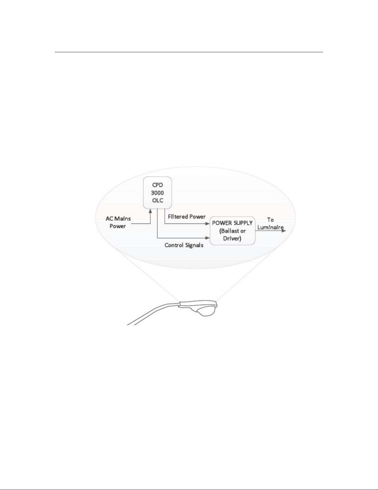
Installation
Installation for the CPD 3000 OLC uses the following steps. It is important to
disconnect line voltage before installing or replacing a CPD 3000 module.
1. Install the CPD 3000 OLC module.
2. Connect the AC mains power to the module.
3. Connect the filtered power output of the CPD 3000 OLC module to the
luminaire power supply (electronic ballast/generator, ballast, or driver).
4. Connect the CPD 3000 control signal wires to the luminaire control input.
Figure 1. CPD 3000 Installed in the Light Fixture
6
Page 7

Wiring Specification and Diagram
Here are the wiring specifications and diagram for US and European models of the
CPD 3000. The CPD 3000 is not suitable for installing above 15,000 feet altitude.
The controller must be installed in the light fixture, inside a street light pole, or in a
street light cabinet. The CPD 3000 is not intended to be installed in an open
outdoor environment.
US Model
Three AWG 16 wires for AC mains input:
Black Line In
White Neutral In or Line 2 In*
Green Ground
*
May be powered Line-to-Line if Line-to-Line Voltage is 100-277 VAC and all CPD 3000s, and the
segment controller, are connected to the same circuit pair.
Three AWG 22 wires for control of signal ouput (IEC60929)
Blue 10V signal for PWM control
Black Ground
Violet Signal for 0-10V control
European Model
Three AWG 16 wires for AC mains input:
Brown Line In
Blue Neutral In or Line 2 In*
Green/Yellow Ground
May be powered Line-to-Line if Line-to-Line Voltage is 100-277 VAC and all CPD 3000s, and the
*
segment controller, are connected to the same circuit pair.
Three AWG 22 wires for control of signal ouput (IEC60929)
Blue 10V signal for PWM control
Black + Signal for 0-10V control
White - Signal for 0-10V control
CPD 3000 Integration Guide 7
Page 8

Two AWG 16 wires for filtered power output (both models)
Red Line Out
Blue Neutral Out or Line 2 Out
The 0-10V control signal of the CDP 3000 works with current sourcing inputs.
The CPD 3000 will sink up to 1500mA. The filtered switch AC output will
handle load up to 500 VA.
CPD 3000 Mechanical Dimensions
This diagram shows the dimensions of the CPD 3000 in millimeters.
Figure 2. CPD 3000 Housing Profile
See the CPD 3000 Outdoor Lighting Controller data sheet (003-0513-01) on the
Echelon web site for all specifications of the CPD 3000.
8
Page 9

2
CPD 3000 Lighting Controller
Interface
The CPD 3000 Lighting Controller borrows much of its
interface from the SFPToutdoorLuminairController
(3512) defined in the LonMark standard resource file set
version 13.10. To meet the memory requirements of the
PL3120-E4 Smart Transceiver, a specific profile is defined in
an Echelon device specific scoped resource file set defined in
the DRF files set EchelonLighting.* (Program ID [scope
4] 80 00001 1E00 03 11 03). These resource definitions were
first defined in version 1.03, and apply to version 1.05, the
current release at thewriting of this document
CPD 3000 Integration Guide 9
Page 10

Application as Function Block
The application for the CPD 3000 is developed as a sole function block. The
UFPTlightingController is referred to as the LC in the remainder of this
document.
Figure 3. UFPTlightingController Funtional Profile Interface used in
CPD 3000
UFPTlightingController Network Variables
The following table describes the network variables defined for the CPD 3000
implementation of the UPFTlightingController. The CPD 3000 implements
only the mandatory network variables and CPs in the initial release.
10
Page 11

Table 1 LC Network UNVTfaults Variables Implemented on the CPD 3000
Network Variable Type Notes
nviLampValue
nviStatReset UNVTstatControl
nvoControlData UNVTcontrolData
nvoLampFb SNVT_switch
SNVT_switch
Primary control input. The level
translates to a 0-10V control signal with
the transform being subject to the values
configure in nciControlConfig defined
below. By default, 50% results in a 5V
control signal to the ballast, driver, or,
generator controlled by the CPD 3000.
Sets/initializes energy, runtime, and
error counts.
A structured variable describing all
current operating values and state of
the LC. This is described in the
following section.
Feedback of the current
nviLampValue. In normal operating
conditions, this value will reflect the
nviLampValue. It may differ if the
heartbeat interval is exceeded and the
defaultLevel differs from the value
in nviLampValue.
nvoLcStatus UNVTfaults
nvoVersion UNVTversion
Feeds alarm logs only on change to
minimize the data requirement on the
IP network. The frequency of changes
to this variable is carefully managed
to conserve bytes consumed by data
logs.
A string describing the version of the
OLC application, such as 1.00.09.
UNVTcontrolData – nvoControlData Details
The LC conserves power line bandwidth by reporting the operating state of the
LC in a single output network variable nvoControlData (UNVTcontrolData),
described in this section. Previous profile designs typically require three poll
CPD 3000 Integration Guide 11
Page 12

transactions to capture level control feedback, environmental variables, and
alarm conditions. This network variable reflects all of this information in one
single-structured data type defined by UFPTcontrolData
.
Figure 4. UNVTcontrolData(nvoControlData) Fields
The fields for UNVTcontrolData are described in table 2.
Table 2 nvoControlData Fields (UNVTcontrolData)
Field Type Notes
power SNVT_power
energy SNVT_elec_kwh_l
runtime UNVTruntime
12
Reflects the instantaneous power consumed by the
LC and controlled fixture. (0.1w resolution) This
value is updated each second by the power
measurement chip on the LC.
Reports the accumulated energy usage to 0.1kwh
resolution. The LC writes this to EEPROM memory
every 12 hours, and at the transition to OFF.
Installations which kill power to the streetlight
segment at dawn should delay the switch of the
power for several minutes after the lights are
scheduled OFF to allow the controller to store this
value in EEPROM memory.
The number of operating minutes for the fixture.
Stored to EEPROM with each OFF transition. The
presentation format for this field is an integer value
of hours.
Page 13

supplyVoltage SNVT_volts
Measured supply voltage 0.1V resolution. This
value is updated every second.
supplyCurrent unsigned long
cycleCount SNVT_count
LevelFB SNVT_lev_cont
faults UNVTfaults
nvUpdates Unsigned
rcvTimeouts SNVT_count
Measured current with 0.01 amp resolution. This
value is updated every second.
Number of operating cycles (ON-OFF). Updated
with each transition to OFF.
0.5% resolution 0-100%. Tracks the .value field of
nvoLampFb. 0% if the state is 0.
Fault bits. Details are provided in the alarms
section. These bits represent current conditions of
the last alarm evaluation and not the latched values
as reflected in nvoLcStatus.
Used to assess application level communication
performance. Every 30 minutes, this field is
updated to report the number of times
nviLampValue was updated in the previous
interval. If the defined heartbeat for
nviLampValue is defined as 10 minutes, this value
reports a value of 2-4 during steady state operation.
The maximum receive timeout for this device (part
of nciControlCfg) is set to three times the control
input heartbeat. In practice, this number increases
only when an update is not received after three
heartbeat intervals.
powerFactor SNVT_pwr_factor
LCtemperature SNVT_temp_p
LCstate OLC_State
Reports the measured power factor for the
LC/Fixture combination. When the controlled load
is OFF, this value will be very low (around .3).
Alarms against power factor are only evaluated
when the load is turned ON. For efficient light
operation, it is good practice to limit the control
signal the CPD 3000 drives to keep the power factor
above 0.8.
Reports the temperature sensed by the power
measurement chip on the CPD 3000. Typical
accuracy is +/-5 degrees C.
Reports the current state of the CPD 3000 LC
controller. Valid values include: OLC_INIT,
OLC_COOLDOWN, OLC_WARMUP, OLC_ON, and
OLC_OFF.
CPD 3000 Integration Guide 13
Page 14

Broadcast Support
The CPD 3000 supports the limited broadcast message support implemented on
SmartServer 2.1 Firmware (service release 1). Control updates through this
mechanism are reflected on the network variable interface (nviLampValue, and
nvoLampFb). Note that the nviLampValue data point should not have a defined
heartbeat to properly use the broadcast feature. Behavior for reflection in
nvoLampFb follows the Use Case Realization described by the LonMark organization
at http://types.lonmark.org/index.html
Enumeration (value) Description Notes
(see SFPTisiLampActuator).
SW_NUL (-1)
SW_SET_OFF (0)
SW_SET_ON (1)
SW_SET_LEVEL (5)
Invalid value
Set state OFF
Set State ON
Set level
This is the initial value for nviLampValue.
The default output state is taken as
unconfigured, and configured nodes with no
hw RTC. Hw RTC nodes that are
configured adopt the state defined by the
backup schedule.
Sets the output state to OFF. The Relay is
open. 0-10v output driven to 0v. If a
rampTime is non-zero, the 0-10v sweeps
from the current value to 0v over the
defined time, which opens the Relay.
Sets the output state to ON, 100% level.
The relay coil is energized, and the level is
set to 100%.
Provide SNVT_switch behavior. Use the
SW_SET_ON, and SW_SET_OFF behaviors
described above. RampTime applies
CPD 3000 Configuration (nciControlCfg)
The CPD 3000 uses a limited number of configuration properties (CPs) implemented
using network variables on the CPD 3000. The main portion of the configuration is
defined by the fields in nciControlCfg (UCPTcontrolCfg).
Configuration
Property
nciControlCfg UNVTcontrolCfg
nviLocation SNVT_geo_position
nciLimit UNVTfaultLimits
14
Type Notes
Defines many of the operating
parameters for the LC.
Provides tagging for GPS
location, and physical asset
tagging. Version 13.04
standard.
Used for alarm thresholds as
defined in Alarming, below.
Page 15

nciPowerProfile UNVTpowerProfile
UNVTControlCfg
This section describes how the fields in this configuration property are applied in the
LC.
Defines the nominal power
measured at 5 commanded
nviLampValues 0.5%, 25%,
50%, 75%, 100%) while driving
the driver/lamp combination.
This CP must be set for
lowPower/HighPower, and
measured with nvoLampFb
values to work correctly. They
will depend on the minPWM and
maxPWM fields defined in the
following section.
Figure 5. UNVTcontrolConfig Field Details
Field Type Notes
defaultLev SNVT_lev_cont
CPD 3000 Integration Guide 15
This is the initial value before an update
to nviLampValue is received by the LC to
drive the lamp value at power ON or reset.
The default value is 100%. This value only
applies after the CPD 3000 is commission
by the SmartServer. When unconfigured,
the CPD 3000 will turn ON the controlled
light to full ON. When power is applied to
the OLC, the application enforces a 10s
minimum time (even if CoolDownTm =0)
before applying this value. A non-zero
Page 16

CoolDownTmwill extend this time.as
required when controlling certain lamp
types such as HPS.
rampTm SNVT_time_sec
Controls how the LC ramps between level
transitions. Only used after the lamp is
ON to go between intermediate steps. The
CPD 3000 limits this value to a maximum
of 30s. (Default value – 1.5s)
supplyVoltage SNVT_volt
The nominal supply voltage for the fixture.
Used of voltage level alarms. (Default
value – 240V).
warmupTm unsigned short
The number of minutes the LC allows the
fixture to warm up before allowing
dimming commands. During warm up, the
dimming commands are deferred. If the
LC is set to go to 75% ON, the LC will set
the 0-10V signal to 10V for warmupTm
minutes before issuing the appropriate
dimming level. In LED applications, this
is typically 0. Any nviLampValue less
than 100% will be delayed while the LC is
in the state OLC_WARMUP. (Default value –
0s). This also delays power alarm
processing which is important in the case
of control of magnetic ballast technology.
coolDownTm unsigned short
The number of minutes the LC will delay
commands to turn ON after the fixture has
been turned OFF. This is important for
improving certain lamp technology life
times. The CPD 3000 enforces a 10s
COOLDOWN to allow recovery of the
inrush protection circuit. This 10s
minimum is subject to change in the
future. (Default value – 0s)
maxRcvTm SNVT_time_sec
If the LC fails to receive an update to
nviLampValue for this time (0s default),
the LC will drive the lamp to the
defaultLevel. The segment controller
should update nviLampValue up to three
times within this period. If the maxRcvTm
is 900s, the heartbeat rate of 300s should
be used by the segment controller. Note
that maxRcvTm = 0 means lights will
retain the last commanded value if the
SmartServer cannot communicate to the
device, or if it fails.
minPWM unsigned long
It may be necessary to set the lowest 010V signal to a value that can be used to
drive the controlled fixture. This value
16
Page 17

lower limit of the PWM output with the
nviLampValue is at 0.5%. Limit to 0-
255. (Default value – 0). Use this to limit
the low level light setting to maintain
efficient operation.
maxPWM unsigned long
pwmClock unsigned short
alarmClrMode FlagManamentMode
clrTime unsigned short
It may be necessary to set the highest 010V signal to a value that can be used to
drive the controlled fixture. This value
upper limit of the PWM output with the
nviLampValue is at 100%. Limit to 0-
255. (Default value – 255)
Allows programming of the PWM clock.
The values (0-7) are valid values as
defined in Neuron C. The default value
of 6 should be used.
Not supported. Controls how the alarm
flags are cleared by the LC. (FL_DAILY is
only supported)
Depending on alarmClrMode, this number
is used to manage automatic clearing of
fault flags. See the section on LC Alarms.
This value is scaled with a 6 minute
resolution. It should be set to allow
for alarm logs to be sent on schedule,
well after sunrise has occurred.
Default = 300
Analog Control
Dimming drivers and ballast controllers will exhibit different end results with
respect to power usage and light output response when subjected to a linear
control signal. An LED fixture with a particular Phillips driver was specified to
operate over the range of 0-10VDC. When tested for power efficiency and visible
light level response, the result was 2-8.6VDC. The fields minPWM and maxPWM are
used to control how nviLampValue.value translates to a control signal that
drives the controlled driver/ballast. The values are determined by experimenting
with an actual controlled fixture. In one particular application, the minPWM value
may be established by monitoring the reported power factor, or the measured
delivered light level of the installed fixture. For example, at 1.5V control signal,
the power factor may be adequate at .82, but the delivered light level is not
adequate until 2.5V. Measuring the control signal while driving a specific driver
is required to determine at what minPWM value, 2.5V is measured. The value for
maxPWM may be determined by observing the measured power or the delivered lux
level to the pavement using a lux sensor. You may find the last volt of control
signal has no effect on the delivered light or power level measured for the load so
you could choose a value for maxPWM at around 240.
CPD 3000 Integration Guide 17
Page 18

Working with the CPD 3000 and the target driver/ballast is required to determine
the limits for the best scaling of the nviLampValue.value to the actual control
signal. These values must be set before the nciPowerProfile initialization can
be determined.
LC Alarm Management
The LC provides rich support for status bits which are derived from the power
measurement chip included in CPD 3000 hardware. Alarms require
characterization of nominal operating conditions defined by various CP fields
described in this section. The current existing alarm conditions are always
reflected in nvoControlData.faults before any time filters are applied. The
alarms reported in nvoControlData.faults have no filters applied and are
potentially quite dynamic at the transition. The CPD 3000 applies several filters
to limit the frequency of alarm events. First, at each state transition (OFF to ON,
or WARMUP to ON) Alarms are not checked for 120s. Second, the network
variable nvoLCstatus contains latched versions of the fault bits that have a 60
second active before setting condition as reported in nvoControlData.faults.
If a defined condition exists of 60s, the alarm flag in nvoLcStatus is set and it
will persist until power to the CPD 3000 is cut, action is taken by updating the
value of nviStatReset, or UNVTcontrolCfg.ClrTm minutes have expired after
the lamp is switched OFF at sunrise.
It is important to understand how alarm conditions are filtered to prevent nuance
alarm conditions. Alarms are only checked if the CPD 3000 state is OLC_ON or
OLC_OFF. If the output level or the state is changed, alarm conditions are not
checked for 120s. If you reset the CPD 3000 at T = 0s, and set control the line
voltage to 100VAC with a 120V nciControlCfg.supplyVoltage value, the
nvoControlData.faults.lowSupplyVoltage flag will not be set until T = 130s
(the transition from OLC_COOLDOWN occurs 10s after reset). To be registered as a
fault in nvoLcStatus, the condition of low supply voltage must exist for an
additional 60s. The flag in nvoLcStatus is latched, and will not be cleared until
the configured time after the CPD 3000 switches the load OFF at sunrise, as
described below.
CP Field Type Notes
nciControlCfg.supplyVoltage SNVT_volt
nciControlCfg.defaultLev SNVT_lev_cont
nciControlCfg.maxRcvTm SNVT_time_sec
Nominal supply voltage for
the installed streetlight
segment. (Default - 240V)
Value to use at reset, or if
maxRcvTmo expires.
(Default: 100%)
The time used to determine
if communication to the
segment controller no
longer exists. At this point,
the RcvTmo alarm is
triggered, and the fixture is
18
Page 19

controlled to defaultLev
(Default –0s; which means
HB checking is disabled)
nciPowerProfile UNVTpowerProfile
Defines the nominal power
at 0.5, 25, 50, 75, 100%
lamp
nviLampValue.value.
Used to determine the
expected power draw using
linear interpolation for
nviLampValue.values in
between steps defined in
the table.
nciLimits.powerLowFault SNVT_lev_cont
The percentage deviation
of expected power below
which the LowPower alarm
is triggered. (Default value
- 15%)
nciLimits.powerHighFault SNVT_lev_cont
The percentage deviation
of expected power above
which a HighPower alarm
is triggered. (Default
value - 15%).
nciLimits.voltageLow SNVT_lev_cont
The percentage deviation
below the configure
supplyVoltage at which
the LowSupplyVoltage
alarm is triggered.
(Default value - 15%).
nciLimits.voltageHigh SNVT_lev_cont
The percentage deviation
above the configured
supplyVoltage at which
the HighSupplyVoltag
alarm is triggered.
(Default value - 15%).
nciLimits.pfLow SNVT_pwr_fact
Power factor alarm point.
Power factor alarms are
only tested when the
controlled load is ON.
(Default value - .65)
nciLimits.rcvHb SNVT_time_sec
The rate at which the
segment controller is
expected to update
nviLampValue. Best
practice is to set this value
at 3x shorter than
nciControlCfg.rcvTmo
(Default value – 0s).
nciLimits.highTemp SNVT_temp_p
The temperature above
which a high temperature
CPD 3000 Integration Guide 19
Page 20

nciLimits.lampFailFault SNVT_lev_cont
The field nciControlCfg.clrTm controls when the alarm flags reported in
nvoLcStatus will be cleared. In an SLV managed lighting system, alarm logs are
scheduled for daily delivery at some point after the sunrise OFF command. For
example, this could be scheduled for 10:00AM. Over the year, sunrise time varies
with the season and the geographic location. For example, it could occur between
5:15 and 7:45 AM. To support proper management of alarms, alarms should not
be cleared until at least five hours or more after sunrise.
nciControlCfg.clrTm should be set to 300 minutes to support clearing of the
alarms after the logs have been delivered.
alarm is triggered.
(Defaults value - 65.0 C)
The threshold of power
drop measured when the
lamp fails. In some
technologies, induction
lights for example, the
power draw at bulb failure
may be quite high.
(Default value - 20%).
Figure 6. Fault Limits
During characterization of a driver/lamp combination, it may be useful to use
nviStatReset.cmd, a value of SM_CLEAR_ALARMS. The following table lists the
fault bits reported by nvoControlData.faults and nvoLCstatus.
Table 3. Fault Bit Reported by nvoControlData.faults, and nvoLCstatus
Fault Bit Condition
LowPower
HighPower
20
Measured power is nciLimits.powerLowFault % below the
expected power
Measured power is nciLimits.powerHighFault % above the
expected power
Page 21

LowSupplyVoltage
HighSupplyVoltage
RelayFailed
FailedStart
Cycling
CommMargin
RcvTmo
HighTemp
LampFailed
LowPF
Measured voltage is nciLimits.voltageLow % below the voltage
defined by nciControlCfg.supplyVoltage
Measured voltage is nciLimits.voltageHigh % above the voltage
defined by nciControlCfg.supplyVoltage
Power measured when the load switch relay is disengaged above 6.0W.
This would occur if the relay contacts were to weld shut.
Not supported at this time
Not supported at this time
Set if no update to nviLampValue is received before
nciLimits.rcvHb. It is recommended that the rcvHb parameter be
set to a value that is 50% longer that the configured update rate for
nviLampValue by the segment controller.
Set if the no update to nviLampValue is received before
nciControlCfg.maxRcvTm. This alarm typically results in the load
under control being driven to the level defined by
nciControlCfg.defaulLev.
Set when the onboard temperature sensor exceeds 65 degrees C.
Occurs when the power measured is below the % low value defined by
nciLimits.lampFailFault.
Set if the power factor of the controlled load falls below nciLimits.pfLow
when the load is ON. It is normal for the power factor reported in
nvoControlData to be in the range of .30-.40 when the load is OFF.
Alarm is only set if the load is ON.
nviLampValue -> nvoLampFb Relationship
The SNVT_switch type defines the range of control from 0-100% which maps to
control voltages between minPWM and maxPWM as determined appropriate for a
particular fixture application. A fixture used near an intersection, for example,
may have a maxPWM of 255 to generated full light output, while the same fixture
applied to a residential street may clip the light level maximum output by setting
maxPMW to 220. The value setting is a %, not a delivered light level. The
response of a driver/ballast is implementation dependent over the range of 0100% level. Ideally the response of the driver over the control range is a
continuous change in light level, or change in measured power. A 0VDC signal to
the driver results in a minimum light level, and power draw for the fixture which
are not 0. It is not uncommon for power at minimum controlled level to be 25% of
full brightness power.
The nvoLampFb typically reports value of nviLampValue. The only time this is
not the case is if the LC is configured to monitor the update rate, and a receive
timeout occurs forcing the brightness to the define nciControlCfg.defaultLev.
CPD 3000 Integration Guide 21
Page 22

The CPD 3000 uses the nciPowerProfile table to define the expected power at
five equally spaced nviLampValue.values (.5%, 25%, 50%, 75%, 100%) once the
minPWM and maxPWM CP fields have been established.
Note that nviLampValue.state is set to -1 at powerup/reset.
CPD 3000 Control Sequence
The CPD 3000 implements the state machine diagram depicted in figure 5 below.
The field nvoControData.LCstate reports the current active state for the
controller. To manage inrush current, the CPD 3000 uses an NTC Thermistor to
limit current inrush current commonly encountered with LED drivers and other
electronic ballasts. To be effective, the device needs a recovery time of 10s after
the load is switched ON. This means that power loss or reset will switch the load
OFF for 10s before turning the load ON. The configuration property field
nciControlCfg.cooldownTm provides additional if required by the load under
control.
Figure 7. CPD 3000 State Diagram
Table 4. CPD 3000 Control State Transition Descriptions
Path Condition Comments
A Power-up or Reset
B
C
D
22
COOLDOWN state timer expires AND (command ON
OR .defaultLev > 0)
COOLDOWN state timer expires AND (.defaultLev ==
0 AND rcvTmo) OR command OFF
(Command ON OR (.defaultLev > 0 AND rcvTmo))
AND .warmup > 0
10s COOLDOWN minimum
enforced for inrush limiter
recovery.
An unconfigured node will
follow this path FULL_ON level
Warmup state always drives
the control signal to the
configured high limit.
Page 23

E WARMUP state timer expires OR commanded OFF
F
G
H command OFF OR (rcvTmo AND .defaultLev == 0)
I
COOLDOWN state timer expires AND (.defaultLev > 0
AND rcvTmo) OR command ON
WARMUP state timer expires AND (commanded ON
OR (rcvTmo AND .defaultLev > 0))
.warmupTm == 0 AND (Command ON OR (rcvTmo
AND .defaultLev > 0)
During the transition from OFF to ON, the CPD 3000 drives the 0-10V control
signal directly to the final level at the time the load switching relay is engaged. If
the CPD 3000 is configured with a nciControlCfg.warmupTm > 0, the control
signal is driven to the 100% level, and finally the level defined by
nviLampValue.value after the warmupTm has completed. Changes in lamp level
while the load is ON are applied as a smooth ramp over the time specified by
nciControlCfg.rampTm (0 – 30.0 s, 0.1s steps). The transition to OFF will sweep
the 0-10V control to the minimum level before releasing the load switching relay.
Updates to nviLampValue are
delayed until out of WARMUP.
Occurs when .warmupTm is > 0
COOLDOWN for at least 10 for
inrush circuit recovery
Creating the CPD 3000 Device on your SmartServer
To create a LONWORKS device, follow these steps. For more information, see
Creating LonWorks Devices in Chapter 5 of the SmartServer User’s Guide.
If you are using the SmartServer in Standalone mode, copy the following files to
the SmartServer flash disk:
• Copy the external interface (XIF) files of the devices to be managed by the
SmartServer to the root/LonWorks/import folder on the SmartServer flash
disk.
• Copy the device resource files to the root/LonWorks/types/user folder.
• If you plan on upgrading the devices using the SmartServer, you need to copy
the devices’ application image files to the root/LonWorks/import folder.
• Reboot the SmartServer.
CPD 3000 Integration Guide 23
 Loading...