

Page 1

®
LONW ORKS
Router
User’s Guide
Revision 3
@
EEEE CCCC HHHH EEEE LLLL OOOO NN
C o r p o r a t i o n
078-0018-01D
NN
®
Page 2

No part of this publication may be reproduced, stored
in a retrieval system, or transmitted, in any form or by
any means, electronic, mechanical, photocopying,
recording, or otherwise, without the prior written
permission of Echelon Corporation.
Echelon, L
ON, LONWORKS, LonBuilder, LonManager,
LonTalk, LonUsers, Neuron, 3120, 3150,and the Echelon
logo are trademarks of Echelon Corporation registered
in the United States and other countries. LonLink,
L
ONMARK , LonSupport, LonMaker, the LONMARK logo,
and the LonUsers logo are trademarks of Echelon
Corporation.
Document No. 79100
Printed in the United States of America.
Copyright ©1992 - 1995 by Echelon Corporation
Echelon Corporation
4015 Miranda Avenue
Palo Alto, CA, 94304, USA
Page 3

FCC NOTICE
Note: This equipment has been tested and found to comply with the limits for a Class A
digital device, pursuant to Part 15 of the FCC Rules. These limits are designed to
provide reasonable protection against harmful interference when the equipment is
operated in a commercial environment. This equipment generates, uses, and can radiate
radio frequency energy and, if not installed and used in accordance with the instruction
manual, may cause harmful interference to radio communications. However, there is no
guarantee that interference will not occur in a particular installation. Operation of
this equipment in a residential area is likely to cause harmful interference in which
case the user will be required to correct the interference at his own expense.
Caution: Changes or modifications not covered in this manual must be approved in
writing by the manufacturer’s Regulatory Engineering department. Changes or
modifications made without written approval may void the user’s authority to operate
this equipment.
VDE NOTICE
This product complies with VDE 0870 Part 30 as a peripheral device. To ensure
continued compliance, this product should only be used in conjunction with other
compliant devices.
CANADIAN DOC NOTICE
This digital apparatus does not exceed the Class A limits for radio noise emissions from
digital appararatus set out in the Radio Interference Regulations of the Canadian
Department of Communications.
Le présent appareil numérique n’émet pas de bruits radioélectriques dépassant les
limites applicables aux appareils numériques de la classe A prescrites dans le
réglement sur la brouillage radioélectrique édicté par le Ministére des Communications
du Canada.
Page 4

Contents
Notices i
1 Introduction
Audience 1-4
Content 1-4
Related Documentation 1-4
1-1
2 Theory of Operation 2-1
LonTalk
Looping Topologies 2-2
Power Line Routers 2-3
Routing Algorithms 2-4
Message Buffers 2-7
®
Protocol Support for Routers 2-2
Repeater 2-4
Bridge 2-4
Configured Router 2-4
Learning Router 2-5
3 Packaged Router Overview 3-1
Mechanical Description 3-2
Switches, Indicators, and Connectors 3-3
ESD Warning 3-4
4 RTR-10 Overview 4-1
Mechanical Description 4-2
RTR-10 Power Requirements 4-5
Power Supply Decoupling and Filtering 4-5
Low Voltage Protection 4-5
Electrical Interface 4-5
ACLK2, BCLK1, and BCLK2 4-7
ACP[4..0] and BCP[4..0] 4-7
~ASVC and ~BSVC 4-7
AXID[4..0] and BXID[4..0] 4-7
PKT 4-8
~RESET 4-9
~SERVICE 4-9
5 Developing a Router with the RTR-10 Module 5-1
Overview 5-2
Using Predefined Transceivers 5-2
Using Custom Transceivers 5-4
LONWORKS Router User’s Guide v
Page 5

6 RTR-10 Design Issues
EMI Design Issues 6-2
Designing Systems for EMC (Electromagnetic Compatibility) 6-2
EMC Design Tips 6-2
ESD Design Issues 6-3
Designing Systems for ESD Immunity 6-3
6-1
7 Installing a Router 7-1
Introduction 7-2
Defining a Network Topology 7-2
Attaching the Router to a Network 7-2
Connecting Power 7-4
Installing the Router on a Network 7-5
Router Installation with Network Management Messages 7-6
Router Installation with the LonMaker® Installation Tool 7-6
Router Installation with the LonManager
Router Installation with the LonBuilder
Testing Router Installation 7-8
Building a Router Mounting Bracket 7-8
®
API 7-6
®
Developer's Workbench 7-7
8 Network Management Messages 8-1
Introduction 8-2
Standard Messages 8-2
Router Specific Messages 8-4
Router Specific Network Management Messages 8-5
Set Router Mode 8-5
Group or Subnet Table Clear 8-5
Group or Subnet Table Download 8-5
Group Forward 8-6
Subnet Forward 8-6
Group No Forward 8-7
Subnet No Forward 8-7
Group or Subnet Table Report 8-7
Router Status 8-8
Far Side Escape Code 8-8
Router Options Set with Write Memory 8-8
Set Routing Algorithm 8-9
Set Buffer Size 8-9
Set Priority Output Buffer Queue Count 8-10
Set Input and Non-Priority Buffer Queue Count 8-11
Appendix A Communications Parameters A-1
Appendix B Software License and Patent Agreement B-1
vi Echelon
Page 6
1
Introduction
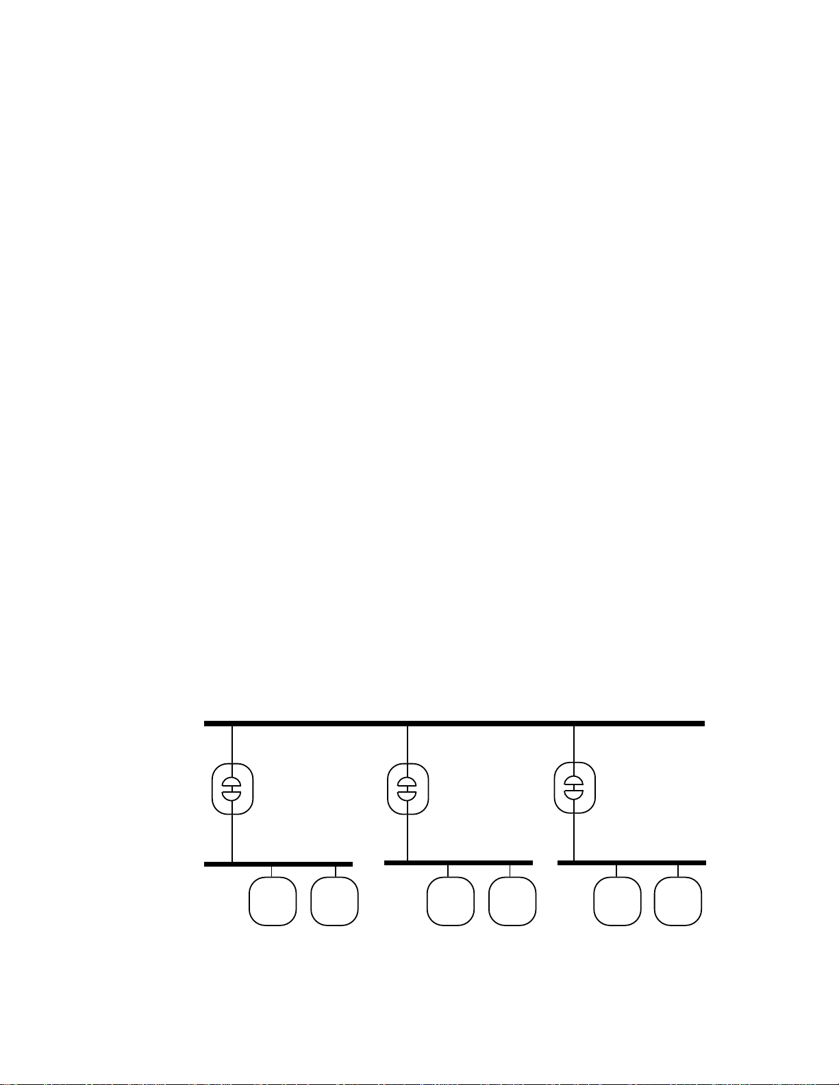
LONWORKS Routers connect two communications channels,
and route LonTalk messages between them. Routers connect
two communication channels and route LonTalk
between them. They support the installation of both small and
large networks with dozens to thousands of nodes.
The following figure illustrates a typical installation with free
topology, power line, and 78kbps bus topology channels
connected to a 1.25Mbps backbone twisted pair channel using
three routers. Because of the routers, the applications on all six
nodes in this example can communicate transparently as if they
were installed on a common channel.
®
messages
TP/XF-1250 Backbone Channel
TP/XF-1250
to
TP/FT-10
Router
TP/FT-10 Channel 1
Node 2
Figure 1.1 Sample Router Installation
TP/XF-1250
to
PL-10
Router
PL-10 Channel 2
TP/XF-1250
to
TP/XF-78
Router
TP/XF-78 Channel 3
Node 5 Node 6Node 3 Node 4Node 1
LONWORKS Router User’s Guide 1-1
Page 7

Routers are used to:
• Extend the limits of a single channel. A router may be used to add a channel to a
L
ONWORKS network to support additional nodes or extend the maximum channel
length. Multiple routers may be added, depending on the capacity or distance
needed.
• Interface different communication media, or bit rates, in a L
ONWORKS network.
For example, it may be desirable to trade data rate for distance on portions of the
network, or to use a 1.25Mbps backbone twisted pair channel to connect several
78kbps free topology and link power channels. Alternatively, it may be desirable
to use power line for a portion of the network where the nodes are subject to
frequent physical relocation, or if cable installation is difficult. In all of these
cases, a router must be used to connect the dissimilar L
ONWORKS channels.
• Enhance the reliability of the LONWORKS network. The two channels connected
to a router are physically isolated, so a failure on one channel does not affect the
other. For example, in an industrial control network, isolation among connected
cells may be desirable to prevent a failure in a single cell from bringing down
multiple cells. This would be achieved by dedicating channels to individual cells
and isolating them from one another with routers.
• Improve overall network performance. Routers can be used to isolate traffic
within subsystems. For example, in a cluster of industrial cells, most of the
communications may be with nodes within cells rather than across cells. Use of
intelligent routers across cells will avoid forwarding messages addressed to nodes
within a cell, thus increasing the capacity and decreasing the response time of
the overall network.
The use of routers across channels is transparent to the application programs within
nodes. Thus, application development can be done independently, without knowledge
of the workings of the routers. Routers need to be taken into account only when
determining the network image of a node. If a node is moved from one channel to
another, only the network image must be changed. Network images are managed by a
network services tool such as the LonManager
®
LonMaker® Installation Tool.
L
ONWORKS routers are offered in a variety of options so that they can be tailored for
specific uses. Options include the following:
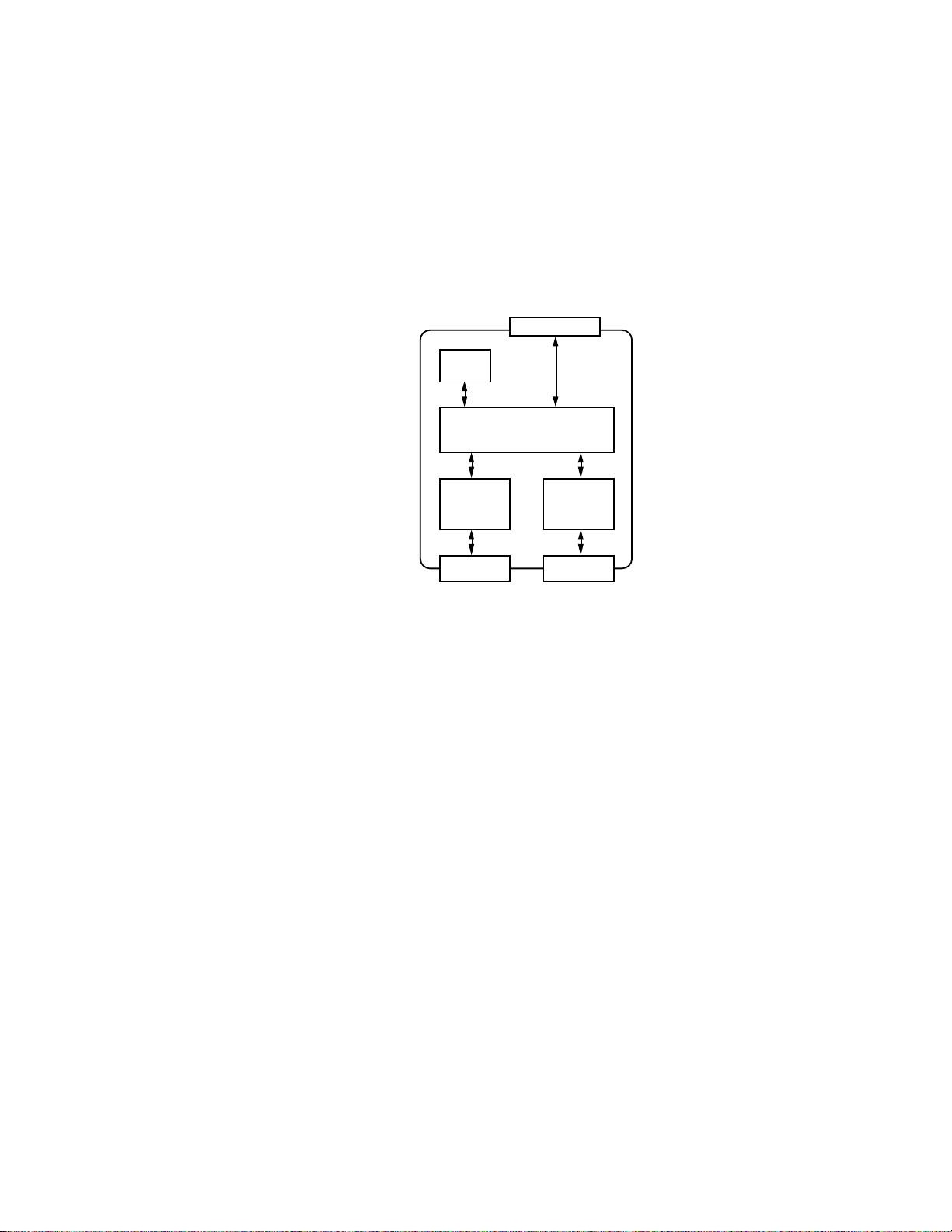
• Integration. Router components are available for embedding in OEM products. An
RTR-10 router and two transceiver modules, one to handle each of two channels
connected by the router, may be mounted on a motherboard, along with a power
supply and two network connectors. This sub-assembly constitutes a custom router.
It can be packaged in an enclosure to meet unique form factor and environmental
requirements. Depending on the application, the package may contain a single
router sub-assembly, or may include other application-specific hardware. See
figure 1.2 for a block diagram of a router based on the RTR-10 router. Multiple
routers may be packaged together for some applications, e.g., a backbone
connecting multiple channels.
1- 2 Introduction
Page 8
Packaged routers, FCC- and VDE-certified to comply with conducted and
k
k
y
radiated emissions specifications and UL-certified for safety, with optional
wall-mount power supplies, are also available from Echelon. These eliminate
the need to build hardware and obtain the necessary electrical interference and
safety certifications. Thus, they allow direct, off-the-shelf integration into the
user's L
ONWORKS network.
Service Button/LEDs
Power
Suppl
RTR-10 Router Core Module
Side A
Transceiver
Side A Networ
Connector
Side B
Transceiver
Side B Networ
Connector
Figure 1.2 Router Assembly Using the Router Core Module
• Routing Algorithm. Routers can use one of four routing algorithms: configured router,
learning router, bridge, or repeater. These options allow system performance to be
traded for ease of installation. Configured and learning routers fall into a class of
routers referred to as intelligent routers, which use routing intelligence to
selectively forward messages based on the destination address. A bridge forwards
all packets that match its domain(s). A repeater forwards all valid packets.
A network services tool such as the LonMaker Installation Tool is used to select the
routing algorithm and calculate network topology as well as layer 4 timing
parameters. Both sides of a router must use the same algorithm. LonBuilder
®
,
LonMaker, or a tool based on the LonManager API is required to install a configured
router.
LONWORKS Router User’s Guide 1-3
Page 9

Audience
Content
The LONWORKS Router User’s Guide provides user instructions for users of
ONWORKS routers and for developers who plan to integrate the RTR-10 router into
L
embedded or standalone routers.
This manual provides detailed information about the hardware and firmware for
ONWORKS routers.
L
• Chapter 1 introduces the LONWORKS routers.
• Chapter 2 discusses a theory of router operation and describes repeaters, bridges,
configured routers, and learning routers.
• Chapter 3 provides an overview of the Model 71000 L
• Chapter 4 provides an overview of the Model 61000 RTR-10 Router Core module.
• Chapter 5 describes how to build a custom router using RTR-10 routers.
• Chapter 6 examines a number of design issues that should be considered when
designing hardware based on the RTR-10 module.
• Chapter 7 lists installation instruction for routers.
• Chapter 8 describes network management services for routers.
• Appendix A lists the default communications parameters for L
• Appendix B includes a copy of the router software license and patent agreement.
Related Documentation
The following Echelon documents provide more information on the router:
• The LonTalk Protocol engineering bulletin summarizes the services available at
each of the seven layers of the LonTalk protocol included with every Neuron
Chip.
• The LonManager LonMaker Installation Tool User’s Guide describes how to
install a router using the LonMaker Installation Tool.
• The LonBuilder User's Guide describes installing a router in a development
network.
• The LonManager Profiler User’s Guide describes how to import a router interface
(.RIF) file to create a router type for LonMaker.
• The LonManager API Programmer's Guide for DOS and the LonManager API
Programmer’s Guide for Windows describe how to install a router using the
LonManager API.
ONWORKS Router.
ONWORKS routers.
®
1- 4 Introduction
Page 10

• The Neuron Chip Data Book describes the Neuron Chip. Descriptions cover
CPUs, memory subsystems, LonTalk protocol, network communications port,
programming model, application I/O, and additional functions.
• The L
ONWORKS TPT Twisted Pair Transceiver Module User's Guide describes
the L
ONWORKS twisted pair transceivers. This is useful for the OEM
implementing a router to interface with a twisted pair channel.
• The L
ONWORKS FTT-10 Free Topology Transceiver User's Guide describes the
L
ONWORKS FTT-10 free topology transceiver. This is useful for the OEM
implementing a router to interface with a TP/FT-10 free topology channel.
• The L
ONWORKS LPT-10 Link Power Transceiver User's Guide describes the
ONWORKS LPT-10 link power transceiver. This is useful for the OEM
L
implementing a router to interface with a link power channel.
• The L
ONWORKS PLT-10A Transceiver User's Guide describes the LONWORKS
PLT-10A Power Line Transceiver. This is useful for the OEM implementing a
router to interface with a PL-10 power line channel.
• The L
ONWORKS PLT-20 Transceiver User's Guide describes the LONWORKS
PLT-20 Power Line Transceiver. This is useful for the OEM implementing a router
to interface with a PL-20 power line channel.
• The L
ONWORKS PLT-30 Transceiver User's Guide describes the LONWORKS
PLT-30 Power Line Transceiver. This is useful for the OEM implementing a router
to interface with a PL-30 power line channel.
• The Junction Box and Wiring Guidelines for Twisted Pair L
ONWORKS Networks
engineering bulletin describes the different types of junction boxes and
interconnections that may be used in twisted-pair L
ONWORKS networks.
• The LONW ORKS Interoperability Guidelines provide the guidelines that are the
basis for obtaining the L
L
ONWORKS interoperable.
ONMARK
™
logo, which indicates that a product is
LONWORKS Router User’s Guide 1-5
Page 11

2
Theory of Operation
This chapter describes the router theory of operation. An
overview is first presented of how the LonTalk protocol
supports routers. This is followed by a discussion of looping
topologies and how they are handled by routers. Then, routing
algorithms are described, followed by a discussion of buffer usage
within routers.
LONWORKS Router User’s Guide 2-1
Page 12

LonTalk Protocol Support for Routers
The LonTalk protocol is designed to provide transparent routing of messages between
nodes that communicate via routers. To increase the efficiency of routers, the LonTalk
protocol defines a hierarchical form of addressing using domain, subnet, and node
addresses. Subnets do not cross intelligent routers, which allows intelligent routers to
make a routing decision based on the subnet component of a node's logical address. To
further facilitate the addressing of multiple dispersed nodes, the LonTalk protocol
defines another class of addresses using domain and group addresses. Intelligent
routers also can be configured to make a routing decision based on the group addressing
component of a message.
In general, a network services tool such as the LonMaker Installation Tool, is
responsible for domain, subnet, node, and group address assignments.
See the LonTalk Protocol engineering bulletin (005-0017-01) for a further description of
the LonTalk protocol. See the L
further description of the installation scenarios.
ONW ORKS Installation Overview (005-0006-01) for a
Looping Topologies
A looping topology is a network topology that has the potential for message loops. A
loop is a path through two or more routers that forwards a message from a channel
back to the same channel. For example, figure 2.1 shows a looping topology with two
channels and two routers. A message on channel A could be forwarded by router 1 to
channel B, then the same message could be forwarded by router 2 back to channel A,
starting an endless loop of forwarded messages.
Channel B
Router 1
Channel A
Figure 2.1 A Looping Topology
The LonTalk protocol does not support topologies where loops can occur. However,
looping topologies may be desirable for the following reasons:
• Increased Reliability. Redundant routers may be used to increase system reliability
by providing multiple paths between two channels.
Router 2
2-2 Theory of Operation
Page 13

• Support for Open Media. Open media such as RF may require redundant routers
with overlapping coverage to ensure complete coverage of an area.
Configured routers can be used to support looping topologies, by configuring the routers
to prevent message loops. For example, the topology in figure 2.1 can be supported if
both routers are configured to forward all messages addressed to subnets on channel B
from channel A; and all messages addressed to subnets on channel A from channel B.
Any groups with members on both channels can only be forwarded by one of the two
routers.
Network services tools such as the LonMaker Installation Tool or custom tools based on
the LonManager API can automatically set up the forwarding tables for configured
redundant routers.
Power Line Routers
A looping topology can be inadvertently created when using power line media.
Passive coupling between different phases of a power line system can cause packets
transmitted on one phase to be received by nodes installed on another phase. A loop
can be formed when active coupling provided by a router is combined with passive
coupling. Figure 2.2 illustrates an example looping topology.
Phase A
to Phase B
Router
Power Line Phase A
▼
▲
▼
Passive
Coupling
▼
Power Line Phase B
Figure 2.2 A Looping Topology with One Router
Routers can be used between power line channels only if the two channels are fully
isolated. This is generally not the case between two phases on the same circuit, but
may be the case between phases on different distribution transformers. Echelon’s
PLCA-10, PLCA-20, or PLCA-30 Power Line Communication Analyzers should be used
to confirm isolation between power line channels before installing power line to power
line routers.
LONWORKS Router User’s Guide 2-3
Page 14

Routing Algorithms
LONWORKS Routers can be installed to use one of four types of routing algorithms:
configured router, learning router, bridge, and repeater. This selection allows system
performance to be traded for ease of installation. The configured router and learning
router algorithms are used to create intelligent routers that selectively forward
messages based on network topology. This section describes the four algorithms. Both
sides of a router must use the same routing algorithm.
The following general rules apply to all four routing algorithms:
• For a message to be forwarded, it must fit into the router's input and output message
buffer. A free input message buffer must be available.
• For a message to be forwarded, it must have a valid CRC code.
• Priority messages are forwarded as priority messages, but with the priority level
of the transmitting side rather than the priority level of the originator of the
message. If the transmitting side has not been installed with a priority value, then
priority messages are not forwarded in a priority slot. The priority message is still
flagged as a priority message, so that if it passes through a second router that is
installed with a priority level, the second router transmits the message in a
priority slot.
Repeater
A repeater is a router which forwards all messages across in both directions,
regardless of the destination or domain of the message. Any valid message (i.e. any
message with a valid CRC code) received will be forwarded.
Bridge
A bridge is a router which forwards all messages received on either of the router's
domains regardless of the message's destination. A bridge is used for spanning one or
two domains.
Configured Router
A configured router is a router which forwards only messages received on either of the
router's domains and which meet the forwarding rules described in figure 2.3. A
forwarding table is used for each domain on each side of the router. Each forwarding
table contains a forwarding flag for each of the 255 subnets and 255 groups in a domain.
As described in figure 2.3, these flags determine whether or not a message should be
forwarded or dropped based on the destination subnet or group address of the message.
The forwarding tables are initialized by a network services tool using the network
management messages described in Chapter 8. By configuring the routing tables based
on network topology, a network services tool can optimize network performance and
make the most efficient use of available bandwidth. As described in the previous
section, configured routers should be used for looping topologies.
2-4 Theory of Operation
Page 15

There are two sets of forwarding tables, one in EEPROM and one in RAM. The
EEPROM table is copied to the RAM table when the router is initially powered-up,
after a reset, and when the router receives the Set Router Mode command with the
Initialize Routing Table option. The RAM table is used for all forwarding decisions.
Several of the operations in figure 2.3 help prevent message loops for service pin
messages. Service pin messages require special handling since they are broadcast to
all nodes on the zero-length domain, and have a source subnet ID of zero. When a
router receives a service pin message with a source subnet ID of zero, the router
modifies the source subnet field of the message to be the router's subnet on the receiving
side. If the receiving side is installed in two domains, two service pin messages are
forwarded, one for each domain. This allows the router to drop the service pin
message if a loop causes the message to be received again on the same side.
Learning Router
A learning router is a router which forwards only messages received on either of the
router's domains and which meet the forwarding rules described in figure 2.2.
Forwarding tables are used as with configured routers, except that the subnet
forwarding tables are updated automatically by the router firmware, rather than
being configured by a network services tool. The group forwarding tables are
configured to always forward (flood) all messages with group destination addresses.
Learning routers learn network topology by examining the source subnet of all messages
received by the router. Since subnets cannot span two channels connected to an
intelligent router, the router can learn which side a subnet is on whenever that subnet
ID appears in the source address.
The subnet forwarding tables are initially configured to forward all messages with
subnet destination addresses. Each time a new subnet ID is observed in the source
address field of a message, its corresponding flag is cleared (i.e., forwarding is
disabled) in the subnet forwarding table. The forwarding flag for the destination
address is then checked to determine whether the message should be forwarded or
dropped. The forwarding flags are all cleared whenever the router is reset, so the
learning process starts over after a reset.
The forwarding flag for a given subnet should never be cleared on both sides of a router.
However, this may occur if a node is moved from one side of a router to the other side.
For example, if subnet 1 is located on side A of a router, the router will learn subnet 1’s
location as soon as it receives a message generated by any node in subnet 1. If any
subnet 1 node is moved to side B without reinstalling it, the router will learn that
subnet 1 is also on side B, and will quit forwarding subnet 1 messages to side A. The
router detects this error and logs it as described in Chapter 8.
LONWORKS Router User’s Guide 2-5
Page 16
Start:
Router receives
message packet
Is message
addressed to either
of the router's
domains?
No
Is message
domain length
zero, source
subnet zero,
addressed as
broadcast?
No
Substitute one or
both domains from
the router, source
subnet = our subnet,
dest subnet zero.
Forward one or
two packets
Yes
Drop
packet
Yes
No
Is message source
subnet zero?
No
Clear subnet
fwd flag *
Is message
addressed to
group?
Yes
Is the group fwd
flag of the dest.
group set to
forward?
Yes
No
No
Is message
domain length
zero, and
Yes
addressed as
broadcast?
Is message
addressed to
subnet/node?
Is the subnet fwd flag
for the dest. subnet
set to forward?
Yes
Yes
Yes
No
Set message
source subnet =
router subnet.
Message must be
addressed as
broadcast or 48-bit
No
NEURON ID
No
Is message dest.
subnet = zero?
Yes
Is the subnet fwd flag
Yes
Drop packet
* Executed only in a learning router
** Executed only in a configured router, otherwise forward
for the source subnet
set to forward ? **
No
Forward packet
Figure 2.3 Configured/Learning Router Forwarding Rules
2-6 Theory of Operation
Page 17
As with configured routers, learning routers sometimes modify source addresses for
service pin messages to help prevent message loops.
Learning routers, in general, are less efficient in using channel bandwidth because they
always forward all messages with group destination addresses. Their advantage is
simplified installation since the installation tool does not need to know the network
topology to configure a learning router.
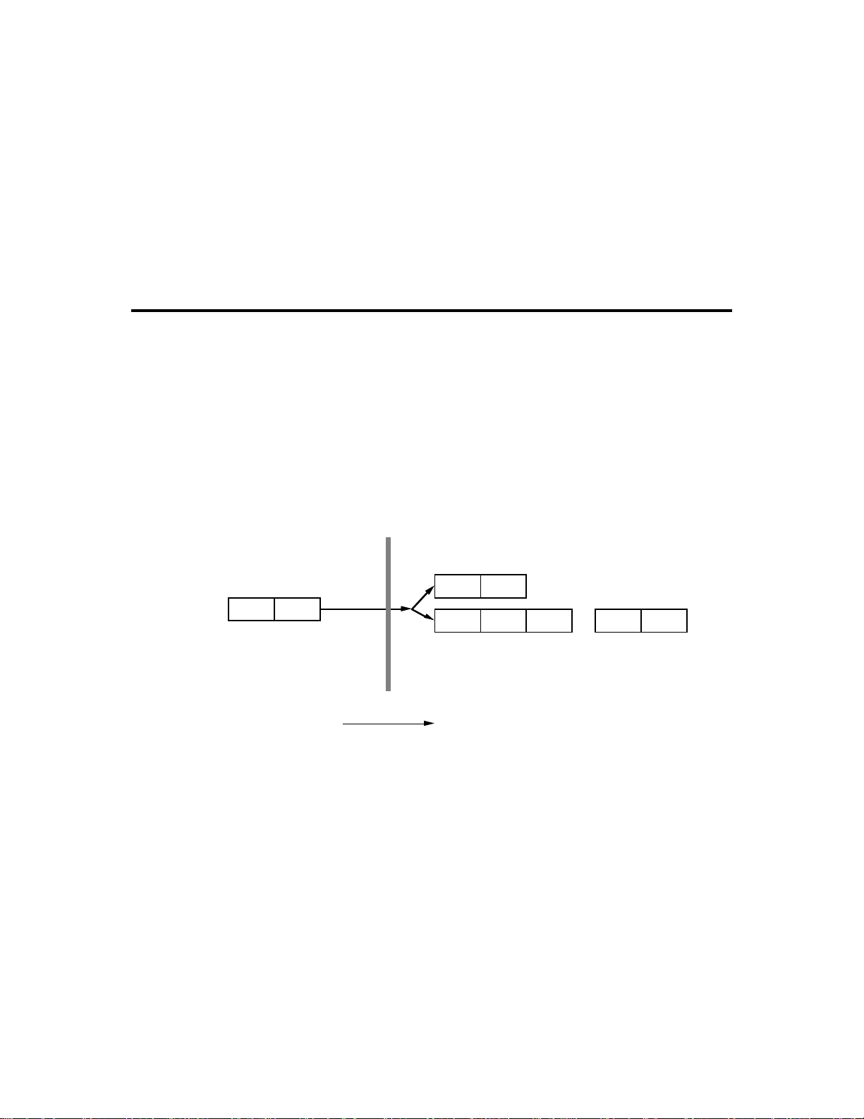
Message Buffers
As messages are received by a router, they are placed in an input buffer queue. By
default, this queue is limited to two message buffers to ensure that priority messages are
never queued behind more than one non-priority message. When forwarded to the
transmitting side of the router, priority messages have their own outgoing buffer queue.
This assures priority processing of these outgoing messages since the transmitting side
will send messages from the priority output buffer queue before sending messages from
the non-priority output buffer queue. Figure 2.4 summarizes the message flow through
the input and output buffer queues. This message flow is duplicated for messages moving
in the opposite direction, i.e., another set of input and output buffer queues exist for
messages flowing in the opposite direction.
Message Receiving Side Message Transmitting Side
Input Buffer Queue
12
Priority Output Buffer Queue
12
1 2 3 n-1 n
Normal Output Buffer Queue
.......
Direction of Message Flow
Figure 2.4 Buffering Scheme for a LONWORKS Router
The size and count of the message buffers is limited by the amount of RAM on the
router. Each router side has 1,254 bytes of buffer space available. By default, this
space is allocated as two input buffers, two priority output buffers, and 15 non-priority
buffers. The default buffers are all 66 bytes, so the total RAM usage for the default
buffers is:
LONWORKS Router User’s Guide 2-7
Page 18

Queue Count Size Total Bytes
Input Buffer Queue 2 66 132
Priority Output Buffer Queue 2 6 6 13 2
Non-Priority Output Buffer Queue 15 66 990
TOTAL 1254
The default size of 66 bytes allows the router to handle packets with maximum
address overhead and data size for any network variable message and explicit
messages with up to 40 bytes of data; this is large enough for any network management
or network diagnostic message. In applications that must route large explicit messages
with more than 40 bytes of data, the buffer size must be increased, and the count of nonpriority buffers decreased. See Chapter 6 of the Neuron C Programmer’s Guide to
understand how the network buffer sizes are calculated. The size and count of buffers
can be changed as described in Chapter 8 of this document. They also can be changed
using the NodeUtil node utility available on the LonLink
™
bulletin board and Internet
Host. The total memory required by the three buffer queues must not exceed 1254 bytes.
The default buffer configuration places the bulk of the buffers on the output queues of
the router. For example, the standard configuration places two network buffers on the
input queue and 17 buffers on the output queue (2 priority and 15 non-priority) of each
router side. The reasoning behind this configuration is to keep buffered packets on the
output queues, after they have been processed for forwarding. This processing includes
checking for priority packets. Priority packets are sensed and forwarded through the
router's priority output buffers. This assures that priority packets are processed as
quickly as possible, rather than allowing them to be delayed behind non-priority
packages in a large input queue.
There are applications, however, where the network traffic may be 'bursty' where
many packets appear on the network almost at the same time. In these cases the
traffic bursts may cause the input queue to become full and loose the excess packets.
In this case it may be preferable to move more of the packet buffering from the output
queue to the input queue. This can be done by increasing the size of the input queue and
decreasing the size of the output queue. A router with a larger input queue can handle
larger bursts of traffic, at the risk of priority messages being queued behind several
non-priority messages.
2-8 Theory of Operation
Page 19

3
Packaged Router Overview
This chapter provides an overview of the Model 71000 LONWORKS
Router hardware. If you are using custom routers based on the RTR10 Router Core Module, skip this chapter.
LONWORKS Router User’s Guide 3-1
Page 20
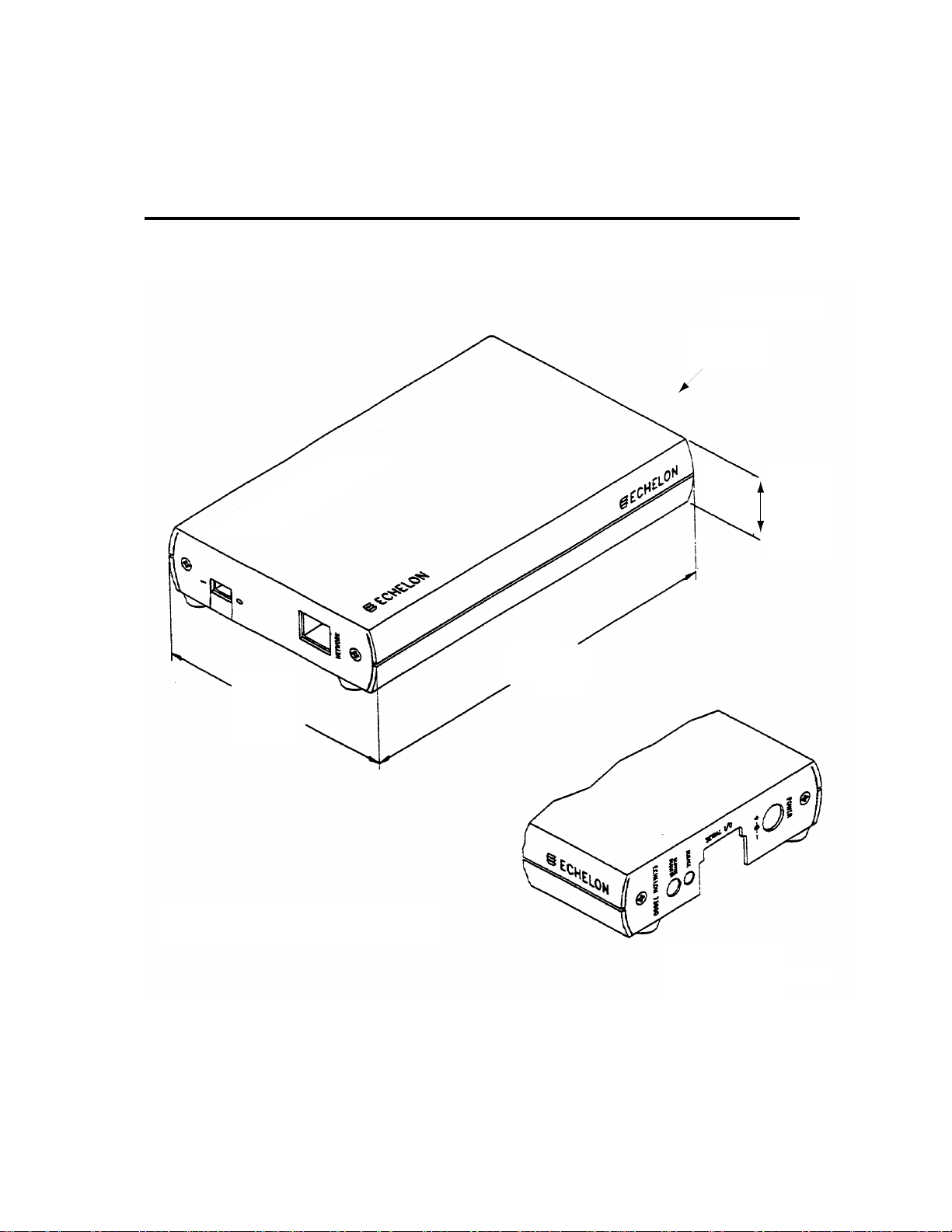
Mechanical Description
The following drawings provide the front and back views of the Model 71000 router.
®
Router
Back View
ORKS
W
ON
L
3.895
[98.93]
All dimensions are in inches with
equiv. mm dimensions in brackets.
1.163 [29.54]
6.62
[168.15]
Back View
Figure 3.1 Router Views - Front and Back (rubber feet not included in the dimensions)
LONWORKS Router User’s Guide 3-1
Page 21

Switches, Indicators, and Connectors
Table 3.1 describes the function of router switches, indicators, and connectors.
Table 3.1 Router Interfaces
Interface Function
Service Request Pressing this switch grounds the service pin to both sides of the
router. When this switch is pressed, both service LEDs should light
to maximum intensity. This action generates service request messages
from each side of the router. For more information, see the Neuron
Chip Data Book.
Service 1 (Yellow LED) When the service request switch is being pressed, this
LED is on at maximum intensity. If the service request switch is not
being pressed, then the LED indicates the following:
on an unrecovered error has been detected on
side one
blinking side one unconfigured; routing tables or
router node address assignment have not
been loaded
off side one configured
Power On (Green LED) Indicates that power is being supplied to the router.
Does not necessarily indicate that the power supply voltage is
within tolerance.
Status (Green LED) Flickers when a packet is being forwarded in either
direction. The rate of flashing can be used as a rough indicator of
router activity level.
Service 2 (Yellow LED) When the service request switch is being pressed, this
LED is on at maximum intensity. If the service request switch is not
being pressed, then the LED indicates the following:
on an unrecovered error has been detected on side two
blinking side two unconfigured; routing tables or router
node address assignment have not been loaded
off side two configured
LONWORKS Router User’s Guide 3-3
Page 22

Table 3.1 Router Interfaces
(continued)
Interface Function
Power Input connector for power supply.
Net 1 RJ-45 modular connector for connecting side one of the router to a
twisted-pair channel.
Net 2 RJ-45 modular connector for connecting side two of the router to a
twisted-pair channel.
ESD Warning
This product contains devices which are sensitive to static electricity. Before
installing or removing network cables, touch earth ground with your hand to discharge
any static electricity which may have accumulated.
3-4 Packaged Router Overview
Page 23

RTR-10 Overview
This chapter provides an overview of the Model 61000 RTR-10
Router Core Module. If you are using the Model 71000 L
Router, skip this chapter.
ONWORKS
4
LONWORKS RTR-10 Module User’s Guide 4-1
Page 24

Mechanical Description
The RTR-10 Router Core Module consists of a 67mm by 23mm by 7mm (2.65” by 0.9” by
0.3”) module with the core electronics and firmware required to implement a router.
The RTR-10 is attached to a motherboard, using a 40-position 0.050-inch spacing SIMM
socket. Two compatible sockets are available:
• AMP 822021-1, MICRO-EDGE SIMM Vertical Connector with metal latches, 0.050
Centerline Single Row Connector - 40 position.
• AMP 4-382483-0, SIMM II Right Angle Connector, 0.050 Centerline Single Row
Connector - 40 position.
Within North America, AMP drawings can be obtained via FAX using the free AMP FAX
service. Call 1-800-522-6752 from a touchtone phone and order customer prints using the
AMP part number. Additional information on the connectors is available in AMP
application note number AMP 114-1060 and reliability information is available in AMP
product specification 108-1297.
Figure 4.1 illustrates the mechanical footprint for the RTR-10 router and vertically
mounted socket. Figure 4.2 shows the recommended PCB pad layout for the vertically
mounted socket. Figures 4.3 and 4.4 provide the same information for the right-angle
socket.
Decisions about component placement on the motherboard must consider electromagnetic
interference (EMI) and electrostatic discharge (ESD) issues discussed in Chapter 6 of this
document.
RTR-10 PCB footprint when using AMP part number 8822021-1
(component side, vertical mounting)
74.93mm
(2.950)
(0.180)
3.17mm
4.57mm
Socket Outline
(0.125)
1
Module Overhang
71.00mm
(2.800)
Notes:
1. Dimensions in mm (inches)
2. Tolerances ± .13mm (0.005)
3. Components standing higher than 3.81mm (.15) should not be closer than 12.4mm (0.5) to this
edge of the socket to allow clearance to insert the module.
4. Allow 33.02mm (1.3) clearance above PCB over the foot print area. Additional clearance required
to insert the module.
5. Socket dimensions are subject to change. Contact AMP for the most current information.
See note 3
7.37mm
Figure 4.1 RTR-10 Vertical Socket Mechanical Foot Print
4-2 RTR-10 Overview
(0.290)
Page 25

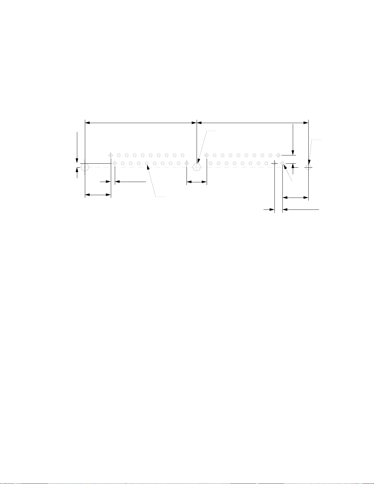
Recommended PCB hole pattern (component side view)
for AMP part number 822021-1 (vertical mounting)
35.56mm 35.56mm
2.41mm
±.03
(0.950 ±.001)
(1.400)
1.63mm
±.03 (x2)
(0.640 ±.001)
(1.400)
2.54mm
40
2
39
1.27mm
(0.050)
8.26mm
6.35mm
(0.250)
1.02mm
±.08 x40
(0.040 ±.003)
Pin 1
8.26mm
(0.325)
Notes:
1. Dimensions in mm (inches)
2. Tolerances ± .13mm (0.005)
3. All socket dimensions are subject to change. Contact AMP for the most current information.
Figure 4.2 RTR-10 Vertical Socket Pad Layout
RTR-10 PCB footprint when using AMP part number 4-382483-0
(component side, horizontal mounting)
(2.950)
(2.650)
(0.170)
74.93mm
67.31mm
Socket Outline
(0.100)
2.54mm
(0.100)
1.27mm
(0.325)
(0.050)
4.32mm
(1.300)
33.02mm
27.94mm
Notes:
1. Dimensions in mm (inches)
2. Tolerances ± .13mm (0.005)
3. Do not position components in the overhang region.
4. Allow 12.7mm (0.5) clearance above PCB over the entire footprint area. Additional clearance required
during assembly to insert the module.
5. Socket dimensions are subject to change. Contact AMP for the most current information.
Module Overhang
1
Figure 4.3 RTR-10 Right-Angle Socket Mechanical Footprint
LONWORKS RTR-10 Module User’s Guide 4-3
(0.670)
15.42mm
Page 26
(0.050)
1.27mm
Recommended PCB hole pattern (component side view)
for AMP part number 4-382483-0 (horizontal mounting)
35.56mm 35.56mm
(1.400)
40
39
1.27mm
8.26mm
(0.325)
Notes:
1. Dimensions in mm (inches)
2. Tolerances ± .13mm (0.005)
3. Socket dimensions are subject to change. Contact AMP for the most current information.
(0.050)
1.02mm
(0.040 ±.003)
(Module overhangs this side)
6.35mm
(0.250)
±.08 (x40)
2.44mm
(0.960 ±.001)
±.03 (x2)
(1.400)
Figure 4.4 RTR-10 Right-Angle Socket Pad Layout
2
2.54mm
(2.54)
Pin 1
8.26mm
2.54mm
(0.100)
1.63mm
(0.064 ±.001)
(0.325)
±.03
4-4 RTR-10 Overview
Page 27

RTR-10 Power Requirements
The RTR-10 router requires a +5VDC ±10% power source with 200mA current.
Power Supply Decoupling and Filtering
The design for the RTR-10 power supply must consider filtering and decoupling
requirements of the RTR-10 router. The power supply filter must prevent noise
generated by the RTR-10 router from conducting onto external wires, and in the case of
DC-DC switching power supplies, must prevent noise generated by the supply from
interfering with module operation. Switching power supply designs must also consider
the effects of radiated EMI.
The RTR-10 router requires a clean power supply to prevent RF noise from conducting onto
the network through active drive circuits. Power supply noise near the network
transmission frequency may degrade network performance.
The RTR-10 router includes 2.2µF and 0.1µF power supply bypass capacitors close to pins
10 and 31. In general, high-frequency decoupling capacitors valued at 0.1µF or 0.01µF
placed near pins 10 and 31 on the motherboard are necessary to reduce EMI.
Low Voltage Protection
It is necessary to include a low voltage protection circuit on the router motherboard to
drive the ~RESET line of the RTR-10 router. See Section 9.4 of the Neuron Chip Data
Book. Failure to include such protection may cause data corruption to configuration
data maintained in EEPROM on the RTR-10 Neuron Chips. In the sample circuit of
figure 5.1, protection is provided via a Motorola MC33164.
Electrical Interface
The pinout of the RTR-10 Router Core Module is shown in table 4.1. See Chapter 6 of
the Neuron Chip Data Book for more information about the use of the Neuron Chip
communication port pins. For the transceiver interface in the sample schematic of
figure 5.1, ESD protection diodes are used on the CP0 and CP1 comm lines, and the center
tap of the twisted pair coupling transformer is bypassed to ground.
LONWORKS RTR-10 Module User’s Guide 4-5
Page 28

Table 4.1 Pinout of the RTR-10 router
Name Function Pin #
ACLK2 A-side output clock 27
ACP0 A-side network communication port 0 8
ACP1 A-side network communication port 1 7
ACP2 A-side network communication port 2 6
ACP3 A-side network communication port 3 9
ACP4 A-side network communication port 4 5
~ASVC A-side service output 12
AXID0 A-side transceiver ID 0 (LSB) 20
AXID1 A-side transceiver ID 1 18
AXID2 A-side transceiver ID 2 17
AXID3 A-side transceiver ID 3 16
AXID4 A-side transceiver ID 4 (MSB) 15
BCLK1 B-side input clock 29
BCLK2 B-side output clock 33
BCP0 B-side network communication port 0 37
BCP1 B-side network communication port 1 38
BCP2 B-side network communication port 2 39
BCP3 B-side network communication port 3 36
BCP4 B-side network communication port 4 40
BXID0 B-side transceiver ID 0 (LSB) 22
BXID1 B-side transceiver ID 1 24
BXID2 B-side transceiver ID 2 23
BXID3 B-side transceiver ID 3 21
BXID4 B-side transceiver ID 4 (MSB) 19
~BSVC B-side service output 28
GND Ground 1, 2, 3, 11, 26, 30, 32,
PKT Packet forward output 14
~RESET Reset input and output 25
~SERVICE Combined service input 13
V
CC
NC No connect 4, 35
+5VDC input 10, 31
34
4-6 RTR-10 Overview
Page 29

ACLK2, BCLK1, and BCLK2
A 10-MHz crystal is provided for Side A of the RTR-10 router, which can only run at 10
MHz. This clock rate allows Side A to be used with transceivers running at interface bit
rates from 9.8kbps to 1.25Mbps. The 10-MHz clock is output on the ACLK2 pin, allowing
Side B to be tied directly to the same clock through pin BCLK1. Thus, no external
components are required to support the same range of bit rates on Side B. The 10-MHz
output can be divided to a lower frequency with external hardware and used as the
input clock for Side B to support transceivers running at interface bit rates as low as
610bps. ACLK2 can drive 5 LS-TTL loads.
ACP[4..0] and BCP[4..0]
The ACP[4..0] and BCP[4..0] signals are connected to the CP[4..0] pins of the core module
Neuron Chips. The function of these pins is described in Chapter 6 of the Neuron Chip
Data Book.
~ASVC and ~BSVC
Each side of the RTR-10 router has an independent service output : ~ASVC for the A
Side and ~BSVC for the B Side. These outputs may be attached to service LEDs as
shown in figure 5.1. The function of the service pin is described in Chapter 9 of Neuron
Chip Data Book. The internal pullup resistor for the service pin on each side is
enabled. The service LEDs reflect the firmware status: blinking means that the router
side is unconfigured, off means that the side is configured, and on means that the side
has failed.
AXID [4..0] and BXID [4..0]
The RTR-10 router comes preconfigured with many common LON WORKS transceiver
parameters. Two sets of five transceiver identification (ID) pins on the RTR-10 router
select the appropriate transceiver type for each side. The transceiver ID inputs
eliminate a manufacturing step by automatically configuring the RTR-10 router for most
transceivers. A special transceiver ID is reserved for programming any custom
transceiver type. This value causes the communication port pins to be configured as all
inputs so that no line will be driven by both the transceiver and RTR-10 Neuron before
the RTR-10 Neuron Chips can be properly configured.
The RTR-10 firmware reads the transceiver ID inputs on power up and reset. If the
router is being powered-up for the first time, or if the transceiver ID is different from
the last time it was powered-up, the parameters specified in table 4.2 are loaded. If
the router is being re-powered-up, and the transceiver ID is not 30, the RTR-10
firmware compares the network bit rate and input clock for the specified transceiver to
the current transceiver parameters. If these parameters don’t match, than all
transceiver parameters are reinitialized. This allows a network services tool to change
parameters, such as the number of priority slots, without the new values being
overwritten by the RTR-10 firmware.
LONWORKS RTR-10 Module User’s Guide 4-7
Page 30

Table 4.2 RTR-10 Router Transceiver IDs
ID Name Media Bit Rate
(bps)
01 (01 hex) TP/XF-78 Transformer-Isolated
78k 10MHz
Input
Clock
Twisted Pair
03 (03 hex) TP/XF-1250 Transformer-Isolated
1.25M 10MHz
Twisted Pair
04 (04 hex) TP/FT-10 Free Topology and
78k 10MHz
Link Power
05 (05 hex) TP/RS485-39 RS-485 Twisted Pair 39k 10MHz
07 (07 hex)
09 (09 hex) PL-10 Spread-Spectrum
1
RF-10 49MHz Radio Frequency 4.9k 5MHz
10k 10MHz
Power Line
10 (0A hex) TP/RS485-625 RS-485 Twisted Pair 625k 10MHz
11 (0B hex) TP/RS485-125 RS-485 Twisted Pair 1.25M 10MHz
12 (0C hex) TP/RS485-78 RS-485 Twisted Pair 78k 10MHz
16 (10 hex)
17 (11 hex)
2
PL-20C C-Band Power Line 5kbps 10MHz
2
PL-20N C-Band Power Line 5kbps 10MHz
18 (12 hex) PL-30 A-Band Power Line 2kbps 10MHz
24 (18 hex) FO-10 Microsym Fiber Optic 1.25M 10MHz
27 (1B hex) DC-78 Direct Connect 78k 10MHz
28 (1C hex) DC-625 Direct Connect 625k 10MHz
29 (1D hex) DC-1250 Direct Connect 1.25M 10MHz
30 (1E hex)
3
Custom Custom N/A N/A
Note: See Appendix A for a listing of the communications parameters for each
transceiver type.
1
Type 7 can only be used on Side B.
2 PL-20C enables the CENELEC-compliant access protocol; PL-20N
disables it.
3
Type 30 can be used for any transceiver type; the communications port is
initially defined as all inputs to prevent circuit conflicts. The side using type
30 must be reprogrammed via the other router side.
PKT
The PKT output can be used as an activity indicator. When packets are passed between
the router sides, PKT will be active. This is the unbuffered IO0 signal from the Neuron
Chips. A pulse stretcher circuit driven by PKT can be used to make an activity LED flash,
as in the example circuit shown in figure 5.1.
4-8 RTR-10 Overview
Page 31
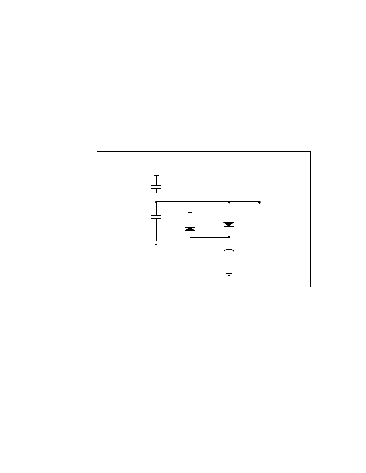
~RESET
The Neuron Chip reset pins are tied together and brought out on one pin. Figure 4.5
shows the reset circuitry on the RTR-10 router. Typical applications do not require
debounce conditioning of a momentary push button attached to the ~RESET pin. The
software response time associated with this input is long enough to effectively provide
a software debounce for switches with a contact bounce settling time as long as 20
milliseconds. The ~RESET signal must be driven low by a low voltage protection circuit
on the router motherboard as described under Low Voltage Protection earlier in this
chapter.
RTR-10 Router Core Module
+5V
Side A ~RESET
Side B ~RESET
2.2 µF
Tantalum
±10%
to pin 25
combined
~RESET
68 pF
+5V
68 pF
Figure 4.5 RTR-10 Reset Circuit
+
~SERVICE
The ~SERVICE input drives both sides of the RTR-10 router from a single input. A pushbutton connected to this pin may be used during installation to broadcast each side’s 48-bit
Neuron ID on its channel. Typical applications do not require debounce conditioning of a
momentary push button attached to the ~SERVICE pin. The software response time
associated with this input is long enough to effectively provide a software debounce for
switches with a contact bounce settling time as long as 20 milliseconds.
LONWORKS RTR-10 Module User’s Guide 4-9
Page 32

5
Developing a Router with the
RTR-10 Module
This chapter describes the process of developing a router based on the
RTR-10 Router Core Module. If you are using the Model 71000
ONWORKS Router, skip this chapter.
L
LONWORKS Router User’s Guide 5-1
Page 33

Overview
To create a router, follow these steps:
1 Build a router motherboard according to the specifications described
in
Chapter 4 and the guidelines described in Chapter 6. The
motherboard may be part of custom application hardware, or may be
a standalone board. Figure 5.1 is a sample motherboard schematic
for a TP/XF-78 to TP/XF-1250 twisted pair router. Additional
transceiver interfaces are described in the next section.
2 Ensure that the communications parameters in the RTR-10 router
are compatible with both of the transceivers. The transceivers listed
in table 4.2 are supported directly by the RTR-10 router as
predefined types. Set the transceiver ID lines to select the proper
transceiver type. For custom transceivers, modify the
communications parameters as described under Using Custom
Transceivers in this chapter.
3 Assemble the router, including the RTR-10 router, 2 transceivers,
and a motherboard.
4 Install the router on a network as described in Chapter 7. The
network may be a development network for initial testing, a
manufacturing network for configuration during manufacture, or a
production network for field installation.
Using Predefined Transceivers
The RTR-10 router includes built-in transceiver parameters for the
transceivers listed in table 4.2. When using any of these transceivers,
the communications parameters are automatically programmed as
described in Chapter 4.
The user's guide for each transceiver contains documentation on the
interface requirements. You also must set the transceiver ID input for
each side of the RTR-10 as shown in table 4.2.
5-2 Developing a Router with the RTR-10 Module
Page 34

Page 35

Using Custom Transceivers
The RTR-10 router can be used with transceivers not listed in table 4.2 as
long as the communications parameters are reprogrammed to match the
custom transceiver. If one side of the router is a predefined transceiver
type, this reprogramming can occur during manufacture or during
field installation. The first four steps of the following procedure
describe how the custom communications parameters are programmed
for one side. If both sides of the custom router will be custom
transceiver types, additional configuration steps will be required as
described in steps 5 - 10.
1 Assuming that the predefined transceiver is on Side A, attach a
transceiver matching one of the predefined types to Side A of the
RTR-10 and select the matching transceiver ID on Side A.
2 Select the custom transceiver type (ID 30) on Side B of the RTR-10
router.
3 Attach a network services tool, such as LonMaker, with a compatible
predefined transceiver to Channel A as shown in figure 5.2.
Network
Management
Tool
Predefined
Transceiver
Predefined
Transceiver
Channel A
Figure 5.2 Configuring Side B
RTR-10
Router
AB
4 Configure the communications parameters on Side B of the RTR-10
router using the network management tool. Side A may be
automatically reconfigured at the same time depending on the
network management tool.
Installation procedures for LonMaker, LonBuilder, and the
LonManager API are described in Chapter 7.
LONWORKS Router User’s Guide 5-4
Page 36

The preceding 4 steps complete the configuration when a single custom
transceiver is used. Proceed with the following 6 steps if two custom
transceivers are to be used with the RTR-10 router.
5 Remove power from the RTR-10 router.
6 Disconnect the predefined transceiver from Side A.
7 Select the custom transceiver ID (type 30) on Side A.
8 Attach the selected custom transceiver to Side B as shown in figure
5.3, leaving the Side B transceiver ID set to 30.
9 Attach a network services tool with a compatible custom transceiver
to Channel B as shown in figure 5.3.
RTR-10
AB
Router
Custom
Transceiver
Channel B
Figure 5.3 Configuring Side A
Network
Management
Tool
Custom
Transceiver
10 Configure the communications parameters on side A of the RTR-
10 router using the network management tool. Side B may be
automatically reconfigured at the same time depending on the
network services tool.
5-4 Developing a Router with the RTR-10 Module
Page 37

RTR-10 Design Issues
This chapter examines a number of design issues, including a
discussion of electromagnetic interference (EMI) and electrostatic
discharge (ESD). If you are using the Model 71000 L
skip this chapter.
ONWORKS Router,
6
LONWORKS Router User’s Guide 6-1
Page 38

EMI Design Issues
The high-speed digital signals associated with microcontroller designs can generate
unintentional Electromagnetic Interference (EMI). High-speed voltage changes
generate RF currents that can cause radiation from a product with a length of wire or
piece of metal that can serve as an antenna.
Products that use the RTR-10 router will generally need to demonstrate compliance
with EMI limits enforced by various regulatory agencies. In the USA, the FCC requires
that unintentional radiators comply with Part 15 level “A” for industrial products, and
level “B” for products that can be used in residential environments. Similar regulations
are imposed in most countries throughout the world. For more information about
regulations, see VDE 0871, Class “B” 1984, and CISPR Publications 22, proposed new
European EMC Standard.
Echelon has designed the RTR-10 router with low enough RF noise levels for design into
level “B” products. Echelon encourages level “B” compliance for all L
compatible products. This section describes design considerations for RTR-10 routerbased products to meet EMI regulations.
Designing Systems for EMC (Electromagnetic
Compatibility)
The RTR-10 router has been designed so that products using it should be able to meet
both FCC and VDE level “B” limits. Careful system design is important to guarantee
that an RTR-10 router-based product will achieve the desired EMC. Information on
designing products for EMC is available in several forms including books, seminars, and
consulting services. This section provides useful design tips for EMC.
ONWORKS-
EMC Design Tips
• Most of the RF noise originates in the CPU portion of the RTR-10 router--which
effectively means the entire board.
• Most of the EMI will be radiated by the network cable and the power cable.
• Filtering is generally necessary to keep RF noise from getting out on the power
cable.
• EMI radiators should be kept away from the RTR-10 router to prevent internal RF
noise from coupling onto the radiators.
• The RTR-10 router must be well grounded to ensure that its built-in EMI filtering
works properly.
6-2 RTR-10 Design Issues
Page 39

• Early EMI testing of prototypes at a certified outdoor range is an extremely
important step in the design of level “B” products. This testing ensures that
grounding and enclosure design questions are addressed early enough to avoid most
last-minute changes.
ESD Design Issues
Electrostatic Discharge (ESD) is encountered frequently in industrial and commercial
use of electronic systems. Reliable system designs must consider the effects of ESD and
take steps to protect sensitive components. Static discharges occur frequently in lowhumidity environments when operators touch electronic equipment. The static voltages
generated by humans can easily exceed 10kV. Keyboards, connectors, and enclosures
provide paths for static discharges to reach ESD sensitive components such as the
Neuron Chip. This section describes techniques to design ESD immunity into RTR-10
router-based products.
Designing Systems for ESD Immunity
ESD hardening includes the following techniques:
• Provide adequate creepage and clearance distances to prevent ESD hits from
reaching sensitive circuitry;
• Provide low impedance paths for ESD hits to ground;
• Use diode clamps or transient voltage suppression devices for accessible, sensitive
circuits
The best protection from ESD damage is circuit inaccessibility. If all circuit components
are positioned away from package seams, the static discharges can be prevented from
reaching ESD sensitive components. There are two measures of "distance" to consider
for inaccessibility: creepage and clearance. Creepage is the shortest distance between
two points along the contours of a surface. Clearance is the shortest distance between
two points through the air. An ESD hit generally arcs farther along a surface than it
will when passing straight through the air. For example, a 20kV discharge will arc
about 0.4 inches (10 mm) through dry air, but the same discharge can travel over 0.8
inches (20mm) along a clean surface. Dirty surfaces can allow arcing over even longer
creepage distances.
LONWORKS Router User’s Guide 6-3
Page 40

When ESD hits to circuitry cannot be avoided through creepage, clearance and ground
guarding techniques, i.e., at external connector pins, explicit clamping of the exposed
lines is required to shunt the ESD current. Consult Protection of Electronic Circuits from
Overvoltages, by Ronald B. Standler,
exposed circuit lines. In general, exposed lines require diode clamps to the power supply
rails or zener clamps to chassis ground in order to shunt the ESD current to ground while
clamping the voltage low enough to prevent circuit damage. The Neuron Chip's
communications port lines are connected directly to the RTR-10 edge connector without
any ESD protection beyond that provided by the chip itself. If these lines will be
exposed to ESD in a custom router, protection must be added to the router motherboard.
for advice about ESD and transient protection for
6-4 RTR-10 Design Issues
Page 41

Installing a Router
This chapter describes how to install LONWORKS routers.
7
LONWORKS Router User’s Guide 7- 1
Page 42

Introduction
To install a router, follow these steps:
1 Define a network topology.
2 Physically attach the router to a LONWORKS network.
3 Connect power to the router.
4 Logically install the router on the network.
5 Test the router installation.
These steps are described in more detail in the following sections.
Defining a Network Topology
There are many possible network topologies when using routers. The first rule for
initial integration is that if a network services tool is used for installation, then a
physical or logical path must exist between the network services tool and the router
targeted for installation. A physical path is created if the network services tool is
connected to the same media as one side of the L
created if one or more active installed routers exist between the L
the network services tool. The routers creating the logical path may be L
Routers, LonBuilder Routers, or custom routers based on the RTR-10 Router Core Module.
The routers in the logical path must be installed, loaded, and online before the new
router may be added to the network.
ONWORKS Router. A logical path is
ONWORKS Router and
ONWORKS
When installing routers on a development network, the LonBuilder or LonManager
Protocol Analyzer can be used to verify that a path exists to a router to be installed. To
verify the existence of a logical path, press the service switch of a powered router. If a
physical or logical path to the protocol analyzer exists, this action will increment the
packets received count. A detailed view of the packet log resulting from the previous
action will show a code of 0x7F; this is the message code for an unsolicited service pin
message.
Attaching the Router to a Network
The next step in installation is to physically attach the router to two channels in a
L
ONWORKS network. It is important to insure that each channel has only one
transceiver type attached to it. Mixing signals from different transceivers will defeat
the collision avoidance algorithms and therefore severely degrade network
performance.
Custom routers based on the RTR-10 Router Core Module are attached to a network as
described in the router developer's documentation. The remainder of this section
describes how to attach the Model 71000 LONWORKS Router.
7-2 Installing a Router
Page 43

The wire used for the network will affect the overall system performance with respect
to distance, stub length, and total number of nodes supported on a single channel. See
the L
ONWORKS FTT-10 Free Topology Transceiver User's Guide for wiring guidelines
for free topology channels; see the L
ONW ORKS LPT-10 Link Power Transceiver User's
Guide for wiring guidelines for link power channels. For TP/XF and TP/RS485 channels,
Echelon recommends the use of UL Level IV, 22 AWG twisted-pair cable for the
network bus as defined in UL's LAN Cable Certification Program, UL document number
200-120 20 M/11/91.
The router can be connected to the bus using a 24 AWG stub with an RJ-45 connector on one end
and flying leads on the other. For free topology and link power channels, the 24 AWG stubs
must be limited to 0.3m (1 foot), with no more than five 24 AWG stubs per segment. Longer
stubs can be used by splicing the 24 AWG stub to the heavier guage wire specified in the free
topology and link power user's guides. See the Junction Box and Wiring Guidelines for
Twisted Pair L
ONWORKS Networks engineering bulletin (part number 005-0023-01) for
information on connecting to a twisted pair channel.
The pin-out for the RJ-45 connector is shown in figure 7.1. The connector is viewed from
the outside, looking in, with the contacts at the top, pin 1 is at the left. The pins are
numbered sequentially, left to right.
18
Pins 1 and 2 Network connections
Pins 3 through 6 No connect
Pin 7 Connected to the signal ground via a 100 ohm resistor
(used for TP/RS485 only)
Pin 8 Reserved
Figure 7.1 RJ-45 Connector
The connection between pin 7 and local signal ground provides a means for reducing
common-mode voltages between nodes on a TP/RS485 channel. In the typical case, pin 7
would be connected to either earth ground or to a separate network ground. A network
ground can be provided by a third conductor or cable shield in the twisted pair cable.
Two 100 ohm resistors within the router are used to limit circulating current when a
network ground is used. For safety, the 100 ohm resistors are actually thermistors
which changes to high impedance if overloaded. See the EIA RS-485 Standard,
Electronic Industries Association, April 1983. This document is available through
Global Engineering Documents in Irvine, California at +1 (714) 261-1455 or (800) 854-
7179.
LONWORKS Router User’s Guide 7- 3
Page 44

Proper electrical termination is essential for each twisted pair channel. Failure to
terminate the network will degrade performance and in some cases eliminate a node’s
ability to communicate to other nodes. For TP/XF and TP/RS485 channels, the
terminator circuits shown in figure 7.2 should be used. The terminators provided with
the LonBuilder and NodeBuilder
™
TP/XF kits also may be used. See the LONW ORKS
FTT-10 Free Topology Transceiver User's Guide for information on terminating a free
topology network; see the L
ONW ORKS LPT-10 Link Power Transceiver User's Guide for
information on terminating a link power network.
59 Ohms
1%
340 Ohms
1%
TP/XF-78, TP/XF-1250,
and TP/RS485
Figure 7.2 Network Termination Circuits for TP/XF and TP/RS485 Networks
Connecting Power
Once the router is physically attached to the desired channels, power must be supplied.
Power is supplied to the Model 71000 L
on the side of the router. The router may be ordered with a wall-mount power supply,
or you can create your own. Four power supply options are available for the router,
depending on the country for which the router is intended. These are USA/Canada,
United Kingdom, Continental Europe, and Japan. The output voltage is a nominal
+9VDC at 500mA. The following table describes the basic characteristics of the four
power supply types.
102 Ohms
1%
.15 µF
10%
.33 µF
10%
All resistors metal film.
All capacitors metal/polyester.
120 Ohms
5 %
Alternate for TP/RS485 only.
ONWORKS Router via the power input connector
Table 7.1 Power Supply Characteristics
Country or
Region
Nominal
Input
Input range
nominal ±10%
Frequency Input connector Echelon
Model #
Voltage
USA/Canada 120 VAC 108-132 VAC 60 Hz 2-prong, NEMA 1-15P 78010
Japan 100 VAC 90 - 110 VAC 50/60 Hz 2-prong, NEMA 1-15P 78040
U.K. 240 VAC 216 - 264 VAC 50 Hz 3-prong, U.K. Plug 78030
Europe 220 VAC 198 - 242 VAC 50 Hz 2-prong, Euro Plug 78020
7-4 Installing a Router
Page 45
Any power supply may be used for the Model 71000 LON WORKS Router that meets the
following specifications: the power input to the router must be +9 to 15VDC at 500mA,
negative tip, outer barrel positive. The connector is a standard female DC power plug
with a 2.1mm inside diameter and 5.5mm outside diameter. LZR Electronics part
number HP-114A, or Radio Shack catalog number 274-1569 will comply.
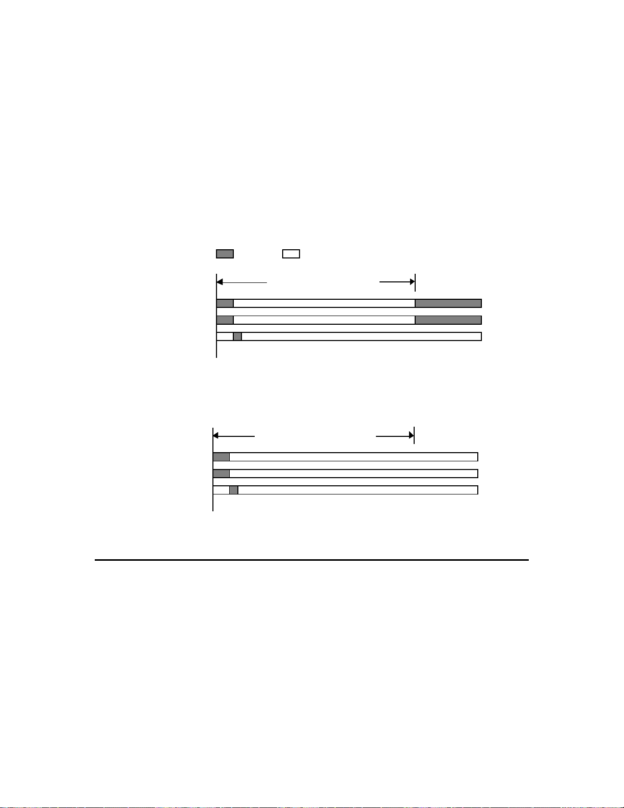
When power is connected to a router, the Status and Service LEDs will change state as
described in figures 7.3 and 7.4. Once a router is powered and configured, the Service
LEDs will stay off unless the service request button is pressed.
ON OFF
2 seconds * (10/input clock)
SERVICE 1
SERVICE 2
STATUS
POWER ON
Figure 7.3 LED Display Timing for Unconfigured Routers
2 seconds * (10/input clock)
SERVICE 1
SERVICE 2
STATUS
POWER ON
Figure 7.4 LED Display Timing for Configured Routers
Installing the Router on a Network
Once a router is physically attached to a network, and powered-up, it must be logically
installed on the network. A router may be installed using a network services tool such
as the LonMaker Installation Tool or the LonBuilder Network Manager, or a custom
network services tool based on the LonManager API. Alternatively, a custom network
services tool can be implemented using the router network management messages
defined in Chapter 8, but this is recommended only for very simple networks with no
more than a few routers due to the complexity of calculating timing parameters and
forwarding tables for complex networks.
LONWORKS Router User’s Guide 7- 5
Page 46

Router Installation with Network Management Messages
Routers can be installed using the network management messages described in Chapter 8
and in Appendix B of the Neuron Chip Data Book, but this process is only recommended
for simple networks with few routers. The process is similar to application node
installation as described in the L
bulletin (number 005-0006-01). To install a router with network management messages,
follow these steps:
1 Change the router state to Unconfigured with the Set Node Mode network
management message.
2 Assign one or two domains, subnets, and node IDs to both sides of the router with the
Update Domain network management message. When installing the router in one
domain, the same domain must be assigned to both sides. When installing the
router in two domains, the same domain must be assigned as the first domain on both
sides, and the same domain must be assigned as the second domain on both sides.
3 Select a routing algorithm for both sides of the router with the Write Memory
network management message as described in Chapter 8. Both sides must be set to
the same algorithm.
4 For configured routers, load the group and subnet routing tables on both sides of the
router with the Group or Subnet Table Download network management message.
There are 255 forwarding flags for subnets and 255 forwarding flags for groups on
each side for each domain.
5 Initialize the routing tables using the Set Router Mode network management
message.
ONWORKS Installation Overview engineering
6 Change the router state on both sides of the router to Configured, on-line with the
Set Node Mode network management message.
Router Installation with the LonMaker Installation Tool
LonMaker is an end-user tool that supports installation of routers and application
devices. See Chapters 4 and 5 of the LonManager LonMaker User’s Guide for a
description of router installation. The channel types should be defined using the
LonManager Profiler based on the communications parameters listed in Appendix C.
Router Installation with the LonManager API
The LonManager API includes functions that simplify the process of installing routers,
and also automatically adjust application node timing parameters based on network
topology. For DOS applications, see Chapter 9, Managing Channels and Routers, of the
LonManager API Programmer's Guide. Also see Chapter 10, Installing and Managing
Routers in the same manual. For Windows applications, see Chapter 10, Installing and
Managing Routers in the LonManager API Programmer’s Guide for Windows.
7-6 Installing a Router
Page 47

Router Installation with the LonBuilder Developer's Workbench
Chapter 9 of the LonBuilder User’s Guide describes how to define and install routers in
a development network using the LonBuilder Network Manager. A prerequisite to
creating router target hardware and node specifications is the definition of the
channels that will be included in the network as defined under Defining Channels in
Chapter 10 of the LonBuilder User's Guide. Routers are initially delivered
programmed with communications parameters listed in Appendix C. These values
should be used in the Std Xcvr Type field when defining channels with the possible
changes discussed next. Be sure to correctly set the minimum clock rate field. If this
field is set incorrectly, excessive collisions will occur. If a channel includes nodes with
a slower clock rate or less accurate clocks, the channel definition must meet this lowest
common denominator for optimal performance.
Additionally, if priority is configured for either channel, then the Number of
Priority Slots needs to be correctly set. If the Average Packet Size expected on
either channel is different than the standard transceiver type, optimal operation of
the collision avoidance algorithm requires that value to be changed also.
When defining the target hardware for the router specify LONWORKS Router for the
Router HW Type field. The assignment of sides A and B to channel names is
arbitrary, and does not have to correspond to the Net 1 and Net 2 assignments on the
router. The LonBuilder Network Manager and the LonManager API will assign the
correct associations when the router is installed.
Set the Packet Buffer count and size fields to the count and size of the non-priority
output buffer queue as described under Message Buffers in Chapter 2.
Set the Clock Rate field to one of the following:
• 10MHz for side A of the RTR-10, and for L
1250 transceivers;
• 5MHz for L
transceivers;
• Match the B-side input clock for side B of the RTR-10. This will typically be
10MHz.
When installing the router, the channel definitions must match the transceivers on the
router, if they do not, the router could lose its ability to communicate. If either of the
channel definitions are modified from the standard transceiver types, then a Yes
response is required to the prompt, Do you want to install communications
parameters? in order for those changes to be programmed in the router; otherwise
specify No.
WARNING: DO NOT use the
ONWORKS Router sides with TP/FT-10, TP/XF-78, or TP/RS485
Yes
response to the prompt:
install communications parameters?
are compatible with the transceivers on the router.
When defining subnets for the router node specification, remember that a subnet may not
span two channels that are connected by intelligent routers. For a L
containing two channels connected with an intelligent router, a minimum of two subnets
must be created, one for each channel. Each side of the router must belong to at least one
ONWORKS Router sides with TP/XF-
Do you want to
unless you have defined channels that
ONWORKS network
LONWORKS Router User’s Guide 7- 7
Page 48

subnet. For managing the assignment of subnets to application nodes, it is helpful to
define subnets with meaningful names that correspond to the channels to which they
are assigned. Bridges and repeaters may have both sides of the router on the same
subnet.
Configured and learning routers are loaded over the network to program the routing
tables, and the subnet/node assignment. An Automatic Load will insure that the router
receives the latest configuration information for subnet and group routing.
Once a router is installed, configured, and loaded, its function in the network becomes
transparent if you allow the network services tool to automatically configure the
transport layer timing parameters of the other nodes in the network. These parameters
are described under Setting Parameters for Connections in Chapter 11 of the LonBuilder
User's Guide. This is the default for each network variable and message tag connection
created. The automatic configuration of these parameters will account for the router
hop delays and adjust accordingly. If a node responds to a network variable that is
several router hops away, but the packet log indicates that retries by the sending node
are frequently occurring, the transport layer timing parameters have probably been
manually set to values that are too low.
Testing Router Installation
Once a router has been installed, the Query Status network diagnostic message can be
used to ensure that it is operational. If no response is received, all intermediate routers
should be queried to determine where the fault occurred. If the router has been
installed with LonMaker, the Test command described under Testing Devices in
Chapter 6 of the LonMaker Installation Tool User’s Guide can be used to query router
status. If the router has been installed on a development network with the LonBuilder
Network Manager, the Test command described under Testing Routers in Chapter 13 of
the LonBuilder User's Guide can be used to query router status. See the description of
the Query Status message in Chapter 8 for a description of the error codes returned by
the Query Status message.
Building a Router Mounting Bracket
The Model 71000 LONWORKS Router may be wall-mounted using a custom mounting bracket. The
following figure is a mechanical drawing of a suitable bracket that can be constructed by any
sheet-metal subcontractor. All measurements are in inches.
7-8 Installing a Router
Page 49
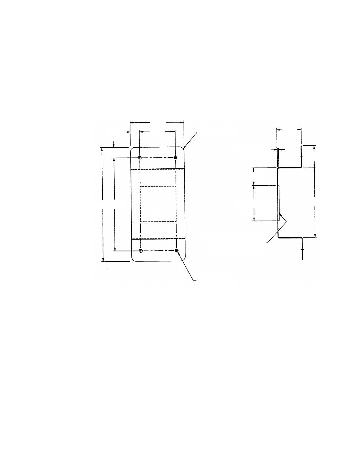
.50
3.00
2.00
4x R.25
1.37
6.46
.60
5.26
3M 4016 DBL SIDE
FOAM TAPE 0.6 THK.
4x 0.190 THRU
Figure 7.5 Router Mounting Bracket
0.6 THK. REF.
.98
2.00 SQ
1.28
3.90
LONWORKS Router User’s Guide 7- 9
Page 50

8
Network Management Messages
This chapter describes network management services for
ONWORKS Routers. These services are used for router installation
L
as described in Chapter 7.
LONWORKS Router User’s Guide 8-1
Page 51

Introduction
As described in the previous chapter, routers are installed using network management
messages. These messages are sent as explicit messages by a network services tool.
Routers respond to many of the same messages as any L
and also have an additional set of router specific messages.
Several router options are set using the Write Memory network management message.
These options are specification of routing algorithm, buffer sizes, and non-priority
output buffer queue count.
Standard Messages
Routers accept the standard network diagnostic and network management messages
listed in tables 5.1 and 5.2. These messages are described in Appendix B of the Neuron
Chip Data Book.
The following exceptions apply to standard network management messages when used
with routers:
• The Query Status network diagnostic message reports two errors that are unique to
the router. These errors are listed in Appendix B of the Neuron data book, but are
not described in Chapter 11 of the Neuron C Reference Guide. The two errors are:
• Subnet inconsistency (159 decimal, 9F hex). A message was received by a
learning router with a source subnet that was inconsistent with the current
subnet forwarding table. To prevent loops, the inconsistent subnet is set to no
forwarding on both sides of the router. A network services tool can use this
error to detect nodes that have been moved between channels. A learning
router with this error logged should be reset by a network services tool to
restart the learning process.
ONWORKS application node,
• Router firmware version mismatch (164 decimal, 0A4 hex). The router
firmware version numbers on the two sides of a router do not match. In most
cases, this error can be ignored, since router firmware normally does
communicate correctly with router firmware of a different version number.
The Query Status network diagnostic message may be used to determine
the firmware version number. This message may be sent using the Test
function of the LonBuilder, LonMaker, or NodeBuilder software.
Routers based on the RTR-10 Router Core Module always have matching
firmware. Packaged routers are based on a pair of router modules. Router
modules may have firmware version numbers of 4, 5, or 125. Router
modules with version 4 firmware communicate correctly only with other
router modules with version 4 firmware. Router modules with version 5
and version 125 firmware communicate correctly with each other. The
following table summarizes the compatibility of router module firmware
versions.
8-2 Network Management Messages
Page 52

Firmware
version
4
Version mismatch,
5
Version mismatch,
125
• The Set Node Mode network management message is automatically processed by
both sides of a router when it is used to place the router offline and online (the
APPL_OFFLINE and APPL_ONLINE options).
• When the Set Node Mode message is used to place a router offline, the router will
stop forwarding and all messages not addressed to the router will be dropped.
• The router will not respond to Set Node Mode messages that use a broadcast
address. This prevents broadcast Restart or Offline messages from stopping the
router and preventing the same broadcast message from reaching destinations on the
other side of the router. Routers must therefore be restarted or taken offline using a
Set Node Mode message addressed directly to the router.
4 5 125
Version mismatch,
No error
incompatible No error
incompatible
Table 8.1 Network Diagnostic Messages
incompatible
Version mismatch, but
Version mismatch, but
compatible No error
Version mismatch,
incompatible
compatible
Network Diagnostic Messages Request
Code
Query Status 0x51 0x31 0x11
Proxy Command 0x52 0x32 0x12
Clear Status 0x53 0x33 0x13
Query XCVR Status 0x54 0x34 0x14
Success
Response
Failed
Response
LONWORKS Router User’s Guide 8-3
Page 53

Table 8.2 Network Management Messages
Network Management Messages Request
Query ID 0x61 0x21 0x01
Respond to Query 0x62 0x22 0x02
Update Domain 0x63 0x23 0x03
Leave Domain 0x64 0x24 0x04
Update Key 0x65 0x25 0x05
Query Domain 0x6A 0x2A 0x0A
Set Node Mode 0x6C 0x2C 0x0C
Read Memory 0x6D 0x2D 0x0D
Write Memory 0x6E 0x2E 0x0E
Checksum Recalculate 0x6F 0x2F 0x0F
Memory Refresh 0x71 0x31 0x11
Router Specific Messages
Router-specific network management messages are listed in table 8.3.
Table 8.3 Router-specific Network Management Messages
Code
Success
Response
Failed
Response
Network Management Messages Request
Code
Set Router Mode 0x74 0x34 0x14
Group or Subnet Table Clear 0x75 0x35 0x15
Group or Subnet Table Download 0x76 0x36 0x16
Group Forward 0x77 0x37 0x17
Subnet Forward 0x78 0x38 0x18
Group No Forward 0x79 0x39 0x19
Subnet No Forward 0x7A 0x3A 0x1A
Group or Subnet Table Report 0x7B 0x3B 0x1B
Router Status 0x7C 0x3C 0x1C
Far Side Escape Code 0x7E – –
Success
Response
Failed
Response
8-4 Network Management Messages
Page 54

Router Specific Network Management Messages
Set Router Mode
This message instructs the router to perform one of several router-related tasks. The
NORMAL option returns the router from the TEMP_BRIDGE mode. The
INIT_RTR_TABLE option copies all forwarding tables from EEPROM into the RAM
tables for a configured router, or, sets all RAM tables to flood for a learning router (this
is the same action that occurs after node reset). The TEMP_BRIDGE option causes the
router to temporarily forward ALL messages in the domain (until the next reset or Set
Router Mode message with the NORMAL option). The Set Router Mode message affects
both router sides. This message is conveyed via the Request-Response protocol.
Note that the standard Set Node Mode message may be used to take the entire router
offline and online.
typedef enum {
NORMAL = 0, // Not a temporary bridge.
INIT_RTR_TABLE = 1, // Copy forwarding tables from EEPROM
// for configured routers.
// Initialize forwarding tables for
// learning routers.
TEMP_BRIDGE = 2 // Temporarily a bridge until next reset
// or NORMAL router mode request.
} rtr_mode;
typedef rtr_mode NM_rtr_mode_request;
Group or Subnet Table Clear
This message is used to clear all entries in either the group or subnet forwarding table
for a single domain for a single router side. The message is segmented to cover eight
byte sections in order to prevent lengthy EEPROM write operations. This message is
conveyed via the Request-Response protocol. The configuration checksum in EEPROM is
updated.
typedef struct {
unsigned group_or_subnet : 1; // 1 => Group, 0 => Subnet
unsigned domain_index : 1;
unsigned unused : 4;
unsigned index_times_8 : 2;
} NM_rtr_table_clear_request;
Group or Subnet Table Download
This message is used to configure the entire group or subnet forwarding table in EEPROM
for the specified domain for a single router side. The download function is broken into
eight-byte sections. This message is conveyed via the Request-Response protocol. The
configuration checksum in EEPROM is updated. Each byte in the table entry includes
routing flags for eight subnets or groups.
LONWORKS Router User’s Guide 8-5
Page 55

The Least Significant Bit (LSB) of the table field maps to the lowest subnet or group ID
in the current set of table entries defined by the index_times_8 field. A value of ‘1’
specifies that forwarding be enabled for the corresponding froup or subnet; a value of ‘0’
disables forwarding. Subnet 0 is used for special protocol functions and is never marked
for forwarding.
typedef struct {
unsigned group_or_subnet : 1; // 1 => Group, 0 => Subnet
unsigned domain_index : 1;
unsigned unused : 4;
unsigned index_times_8 : 2;
unsigned table[8]; // Table data
} NM_rtr_table_downld_request;
Group Forward
This message sets the forwarding flag in the forwarding table for a given group in the
specified domain. If the ram_or_eeprom field is set, both the RAM and EEPROM
flags are set, otherwise only the RAM flag is set, allowing temporary forwarding for a
given group. This message is conveyed via the Request-Response protocol. The
configuration checksum in EEPROM is updated if EEPROM is changed.
typedef struct {
unsigned unused1 : 1;
unsigned domain_index : 1;
unsigned unused2 : 5;
unsigned ram_or_eeprom : 1; // 0 => RAM, 1 => RAM + EEPROM
unsigned group;
} NM_rtr_group_fwd_request;
Subnet Forward
This message sets the forwarding flag in the forwarding table for a given subnet in the
specified domain. If the ram_or_eeprom field is set, both the RAM and EEPROM
flags are set, otherwise only the RAM flag is set, allowing temporary forwarding for a
given subnet. This message is conveyed via the Request-Response protocol. The
configuration checksum in EEPROM is updated if EEPROM is changed.
typedef struct {
unsigned unused1 : 1;
unsigned domain_index : 1;
unsigned unused2 : 5;
unsigned ram_or_eeprom : 1; // 0 => RAM, 1 => RAM + EEPROM
unsigned subnet;
} NM_rtr_subnet_fwd_request;
8-6 Network Management Messages
Page 56

Group No Forward
This message clears the forwarding flag in the forwarding table for a given group in the
specified domain. If the ram_or_eeprom field is set, both the RAM and EEPROM
flags are cleared, otherwise only the RAM flag is cleared, allowing temporary control
of forwarding for a given group (see the Router Status message). This message is
conveyed via the Request-Response protocol. The configuration checksum in EEPROM is
updated if EEPROM is changed.
typedef struct {
unsigned unused1 : 1;
unsigned domain_index : 1;
unsigned unused2 : 5;
unsigned ram_or_eeprom : 1; // 0 => RAM, 1 => RAM + EEPROM
unsigned group;
} NM_rtr_group_nofwd_request;
Subnet No Forward
This message clears the forwarding flag in the forwarding table for a given subnet in
the specified domain. If the ram_or_eeprom field is set, both the RAM and EEPROM
flags are cleared, otherwise only the RAM flag is cleared, allowing temporary control
of forwarding for a given subnet. This message is conveyed via the Request-Response
protocol. The configuration checksum in EEPROM is updated if EEPROM is changed.
typedef struct {
unsigned unused1 : 1;
unsigned domain_index : 1;
unsigned unused2 : 5;
unsigned ram_or_eeprom : 1; // 0 => RAM, 1 => RAM + EEPROM
unsigned subnet;
} NM_rtr_subnet_nofwd_request;
Group or Subnet Table Report
This message is used to report the current settings of either group or subnet forwarding
tables in EEPROM or RAM for the specified domain for a single router side. The report
function is broken into eight byte sections. This message is conveyed via the RequestResponse protocol.
WARNING: This message is only supported by router firmware version 5 or later.
Use of this message with earlier versions of the router firmware will cause the
router to become inoperable.
LONWORKS Router User’s Guide 8-7
Page 57

typedef struct {
unsigned group_or_subnet : 1; // 1 => Group, 0 => Subnet
unsigned domain_index : 1;
unsigned ram_or_eeprom : 1; // 0 => RAM, 1 => EEPROM
unsigned unused : 3;
unsigned index_times_8 : 2;
} NM_rtr_table_report_request;
typedef struct {
unsigned table[8]; // Table data
} NM_rtr_table_report_response;
Router Status
This message is used to report the router configuration and flood/normal modes. This
message is conveyed via the Request-Response protocol.
typedef enum {
CONFIGURED = 0,
LEARNING = 1,
BRIDGE = 2,
REPEATER = 3
} algorithm;
typedef enum {
NORMAL = 0, // Not a temporary bridge.
INIT_RTR_TABLE = 1, // Copy forwarding tables from EEPROM
// for configured routers.
// Initialize forwarding tables for
// learning routers.
TEMP_BRIDGE = 2 // Temporarily a bridge until next reset.
} rtr_mode;
typedef struct {
algorithm type; // CONFIGURED, LEARNING, BRIDGE,
// or REPEATER
rtr_mode mode; // TEMP_BRIDGE or NORMAL
} NM_rtr_status_response;
Far Side Escape Code
When this message code is placed in the message and is followed by any network
management or network diagnostic message (except the escape message itself); that
message will be passed over to the other (far) router side for processing. Any responses are
returned in the normal manner. This allows network management of the router side which
is not directly addressable from a network services tool.
8-8 Network Management Messages
Page 58

The far side escape tool is not required for the Set Node Mode network management
message when it is used to place the router offline and online (the APPL_OFFLINE and
APPL_ONLINE options). The offline and online commands are automatically forwarded.
byte code; /* Destination: NM, code: 0x7E */
Router Options Set With Write Memory
The Write Memory network management message is used to change the routing
algorithm, buffer sizes, and buffer queue counts. To change these parameters, follow
these steps:
1 Change the parameters using the Write Memory network management message as
described in the following sections.
2 Reset the router using the Set Node Mode network management message.
Set Routing Algorithm
The routing algorithm is selected using a Write Memory network management message
with the following parameters:
mode = CONFIG_RELATIVE (2)
offset = 0x0037;
count = 1;
form = CNFG_CS_RECALC (4)
data =
The routing_algorithm value is a byte of type algorithm:
typedef enum {
CONFIGURED = 0,
LEARNING = 1,
BRIDGE = 2,
REPEATER = 3
} algorithm;
routing_algorithm
;
Set Buffer Size
The buffer sizes are selected using a Write Memory network management message with
the following parameters:
mode = READ_ONLY_RELATIVE (1)
offset = 0x0019;
count = 1;
form = BOTH_CS_RECALC (1)
data =
The buffer_sizes value contains two nibble fields which control the size of both the input
and output buffers. The output size value also controls the priority output buffer size. The
default size is 66 bytes, or code (SIZE_66 = 0xB). When changing this value you should
set both nibble fields to the same value. Different values may be used if the maximum
packet size is different for the two directions through the router. The default setting for
this byte is 0xBB. The total number of bytes assigned to the buffer queues must not exceed
1254 bytes as described under Message Buffers in Chapter 2. A buffer size of less than 66 is
LONWORKS Router User’s Guide 8-9
buffer_sizes;
Page 59

not recommended because the router will not be able to forward network management
messages if the buffers are too small.
The size values are represented by a code of type buffer_size_entry:
typedef enum {
SIZE_20 = 0x2;
SIZE_21 = 0x3;
SIZE_22 = 0x4;
SIZE_24 = 0x5;
SIZE_26 = 0x6;
SIZE_30 = 0x7;
SIZE_34 = 0x8;
SIZE_42 = 0x9;
SIZE_50 = 0xA;
SIZE_66 = 0xB;
SIZE_82 = 0xC;
SIZE_114 = 0xD;
SIZE_146 = 0xE;
SIZE_210 = 0xF;
SIZE_255 = 0x0;
} buffer_size_entry;
Set Priority Output Buffer Queue Count
The priority output buffer queue count is selected using a Write Memory network
management message with the following parameters:
mode = READ_ONLY_RELATIVE (1)
offset = 0x001A;
count = 1;
form = BOTH_CS_RECALC (1)
data =
The
queue_count
controls the number of priority output buffers. The least significant nibble must be zero.
The total number of bytes assigned to the buffer queues must not exceed 1254 bytes as
described under Message Buffers in Chapter 2.
queue_count
value contains two nibble fields. The most significant nibble
;
The most significant nibble of
queue_count_entry:
typedef enum {
COUNT_1 = 0x2;
COUNT_2 = 0x3;
COUNT_3 = 0x4;
COUNT_5 = 0x5;
COUNT_7 = 0x6;
COUNT_11 = 0x7;
COUNT_15 = 0x8;
COUNT_23 = 0x9;
COUNT_31 = 0xA;
COUNT_47 = 0xB;
COUNT_63 = 0xC;
} queue_count_entry;
queue_count
is represented by a code of type
8-10 Network Management Messages
Page 60

Set Input and Non-Priority Output Buffer Queue Count
The buffer queue counts are selected using a Write Memory network management
message with the following paramters:
mode = READ_ONLY_RELATIVE (1)
offset = 0x001C;
count = 1;
form = BOTH_CS_RECALC (1)
data =
The queue_counts value contains two nibble fields which control the count of both the
input and non-priority output buffer queues. The least significant nibble controls the
number of input buffers and the most significant nibble controls the number of nonpriority output buffers. The default for this field is 15 non-priority output buffers
(COUNT_15) and 2 input buffers (COUNT_2). The total number of bytes assigned to the
buffer queues must not exceed 1254 bytes as described under Message Buffers in Chapter
2. The queue count for both queues is represented by the source code as that for Set
Priority Output Buffer Queue Count above.
queue_counts
;
LONWORKS Router User’s Guide 8-11
Page 61

Appendix A
Communications Parameters
LONWORKS Routers are initially programmed with communications
parameters as listed in this appendix. Parameters for L
approved transceivers correspond to the parameters defined by the
ONWORKS Interoperability Guidelines. The parameters specified as
L
“Configurable” may be changed by a network services tool.
These parameters only apply to routers with router firmware version
5 or newer. The firmware version number for a router can be
determined with the LonMaker or LonBuilder test command or with
the Query Status network diagnostic message. The LonMaker test
command is described under Testing Devices in Chapter 6 of the
LonMaker User’s Guide. The LonBuilder test command is described
under Testing Routers in Chapter 13 of the LonBuilder User’s Guide.
The Query Status network diagnostic message is described in
Appendix B of the Neuron data book.
ONMARK-
Communications parameters for routers with version 4 or older
firmware should be re-installed to ensure that the standard
interoperable parameters are used.
LONWORKS Router User’s Guide A-1
Page 62

Parameter TP/XF-78 TP/XF-1250 TP/FT-10 TP/RS485-
39
Transceiver ID 1 (01 hex) 3 (03 hex) 4 (04 hex) 5 (05 hex)
Media Isolated
Neuron Chip to Transceiver
Interface
Interface Bit Rate 78kbps 1.25Mbps 78kbps 39kbps
Input Clock 5/10MHz* 10MHz 5/10MHz* 5/10MHz*
Minimum Clock Configurable;
Number of Priority Slots Configurable;
Average Packet Size Configurable;
Oscillator Accuracy 200ppm 200ppm 200ppm 200ppm
Oscillator Wakeup 0µsec 0µsec 0µsec 0µsec
Collision Detect (CD) No No No No
CD Term after Preamble N/A N/A N/A N/A
CD Through Packet End N/A N/A N/A N/A
Bit Sync Threshold 5 bits 7 bits 4 bits 4 bits
Hysteresis 2 0 N/A N/A
Filter 1 0 N/A N/A
Network Bit Rate 78kbps 1.25Mbps 78kbps 39kbps
Alternate Rate N/A N/A N/A N/A
Wakeup Pin Direction N/A N/A N/A N/A
XCVR Controls Preamble N/A N/A N/A N/A
General Purpose Data N/A N/A N/A N/A
Allow Node Override N/A N/A N/A N/A
Receive Start Delay 2.9 bits 14.0 bits 9.0 bits 2.0 bits
Receive End Delay 0.0 bits 0.0 bits 0.0 bits 0.0 bits
Indeterminate Time 24.0 bits 25.0 bits 24.0 bits 4.0 bits
Min. Interpacket Time 0.0 bits 0.0 bits 0.0 bits 0.0 bits
Turnaround Time 0µsec 0µsec 0µsec 0µsec
Missed Preamble 1.0 bits 4.0 bits 4.0 bits 1.0 bits
Preamble Length N/A N/A N/A N/A
Use Raw Data No No No No
Twisted Pair
Differential Differential Single-Ended Single-Ended
default = 5MHz
default =
4 slots
default =
15 bytes
Isolated
Twisted Pair
Configurable;
default =
10MHz
Configurable;
default =
16 slots
Configurable;
default =
15 bytes
Free Topology
and Link Power
Configurable;
default = 5MHz
Configurable;
default = 4 slots
Configurable;
default =
15 bytes
RS-485
Twisted Pair
Configurable;
default = 5MHz
Configurable;
default =
4 slots
Configurable;
default =
15 bytes
*The input clock rate is 10MHz for these transceivers on the Model 61000 RTR-10 Router Core Module; the
input clock rate is 5MHz for these transceivers on the Model 71000 L
ONWORKS Router.
A-2 Communications Parameters
Page 63

Parameter RF-10 PL-10 PL-20C
Transceiver ID 7 (07 hex) 9 (09hex) 16 (10 hex)
Media 49MHz Radio
Neuron Chip to Transceiver
Interface
Interface Bit Rate 4.9kbps 625kbps 156.3kbps
Input Clock 5MHz 10MHz 10MHz
Minimum Clock Configurable;
Number of Priority Slots Configurable;
Average Packet Size Configurable;
Oscillator Accuracy 200ppm 200ppm 200ppm
Oscillator Wakeup 0µsec 0µsec 0µsec
Collision Detect (CD) No N/A N/A
CD Term after Preamble N/A N/A N/A
CD Through Packet End N/A N/A N/A
Bit Sync Threshold 7 bits N/A N/A
Hysteresis N/A N/A N/A
Filter N/A N/A N/A
Network Bit Rate 4.9kbps 9412bps 3987bps
Alternate Rate N/A 0bps N/A
Wakeup Pin Direction N/A Output Output
XCVR Controls Preamble N/A Yes Yes
General Purpose Data N/A 00 0A 00 00 00
Allow Node Override N/A Yes No
Receive Start Delay 2.0 bits 1.0 bit 6.8 bits
Receive End Delay 0.0 bits 10.4 bits 1.6 bits
Indeterminate Time 9.8 bits 0.0 bits 0.0 bits
Min. Interpacket Time 0.0bits 0.0 bits 17.5 bits
Turnaround Time 0µsec N/A N/A
Missed Preamble 9.0 bits N/A N/A
Preamble Length N/A 36.7 bits 33.5 bits
Use Raw Data No No No
Frequency
Single-Ended Special Purpose Special Purpose
default = 5MHz
default = 4 slots
default = 15 bytes
Power Line Power Line
Configurable;
default = 5MHz
Configurable;
default = 8 slots
Configurable;
default = 15 bytes
00 00
Configurable;
default = 1.25MHz
Configurable;
default = 8 slots
Configurable;
default = 15 bytes
4A 00 00 00 00
00 00
* The input clock rate is 10MHz for these transceivers on the Model 61000 RTR-10 Router Core Module;
the input clock rate is 5MHz for these transceivers on the Model 71000 L
ONWORKS Router.
LONWORKS Router User’s Guide A-3
Page 64

Parameter PL-20N PL-30
Transceiver ID 17 (11 hex) 18 (12 hex)
Media Power Line Power Line
Neuron Chip to Transceiver
Interface
Interface Bit Rate 156.3kbps 625kbps
Input Clock 10MHz 10MHz
Minimum Clock Configurable; default =
Number of Priority Slots Configurable; default =
Average Packet Size Configurable; default =
Oscillator Accuracy 200ppm 200ppm
Oscillator Wakeup 0µsec 0µsec
Collision Detect (CD) N/A N/A
CD Term after Preamble N/A N/A
CD Through Packet End N/A N/A
Bit Sync Threshold N/A N/A
Hysteresis N/A N/A
Filter N/A N/A
Network Bit Rate 3987bps 1882bps
Alternate Rate N/A N/A
Wakeup Pin Direction Output Output
XCVR Controls Preamble Yes Yes
General Purpose Data 0E 01 00 00 00
Allow Node Override No Yes
Receive Start Delay 6.8 bits 1.0 bit
Receive End Delay 1.6 bits 10.4 bits
Indeterminate Time 0.0 bits 0.0 bits
Min. Interpacket Time 17.5 bits 0.0 bits
Turnaround Time N/A N/A
Missed Preamble N/A N/A
Preamble Length 33.5 bits 36.7 bits
Use Raw Data No No
Special Purpose Special Purpose
1.25MHz
8 slots
15 bytes
00 00
Configurable; default
= 5MHz
Configurable; default
= 12 slots
Configurable; default
= 15 bytes
00 8A 00 00 00
00 00
*The input clock rate is 10MHz for these transceivers on the Model 61000 RTR-10 Router Core Module; the
input clock rate is 5MHz for these transceivers on the Model 71000 L
ONWORKS Router.
A-4 Communications Parameters
Page 65

Parameter TP/RS485-
625
Transceiver ID 10 (0A hex) 11 (0B hex) 12 (0C hex)
Media RS-485 Twisted
Neuron Chip to Transceiver
Interface
Interface Bit Rate 625kbps 1.25Mbps 78kbps
Input Clock 10MHz 10MHz 10MHz
Minimum Clock Configurable;
Number of Priority Slots Configurable;
Average Packet Size Configurable;
Oscillator Accuracy 200ppm 200ppm 200ppm
Oscillator Wakeup 0µsec 0µsec 0µsec
Collision Detect (CD) No No No
CD Term after Preamble N/A N/A N/A
CD Through Packet End N/A N/A N/A
Bit Sync Threshold 4 bits 4 bits 4 bits
Hysteresis N/A N/A N/A
Filter N/A N/A N/A
Network Bit Rate 625kbps 1.25Mbps 78kbps
Alternate Rate N/A N/A N/A
Wakeup Pin Direction N/A N/A N/A
XCVR Controls Preamble N/A N/A N/A
General Purpose Data N/A N/A N/A
Allow Node Override N/A N/A N/A
Receive Start Delay 2.0 bits 2.0 bits 2.0 bits
Receive End Delay 0.0 bits 0.0 bits 0.0 bits
Indeterminate Time 4.0 bits 4.0 bits 4.0 bits
Min. Interpacket Time 0.0 bits 0.0 bits 0.0 bits
Turnaround Time 0µsec 0µsec 0µsec
Missed Preamble 1.0 bit 1.0 bit 1.0 bit
Preamble Length N/A N/A N/A
Use Raw Data No No No
Pair
Single-Ended Single-Ended Single-Ended
default = 5MHz
default = 4 slots
default =
15 bytes
TP/RS485-
1250
RS-485 Twisted
Pair
Configurable;
default = 5MHz
Configurable;
default = 16 slots
Configurable;
default =
15 bytes
TP/RS485-78
RS-485 Twisted Pair
Configurable;
default = 5MHz
Configurable;
default = 4 slots
Configurable;
default = 15 bytes
* The input clock rate is 10MHz for these transceivers on the Model 61000 RTR-10 Router Core Module;
the input clock rate is 5MHz for these transceivers on the Model 71000 L
ONWORKS Router.
LONWORKS Router User’s Guide A-5
Page 66

Parameter FO-10 DC-78 DC-625 DC-1250
Transceiver ID 24 (18 hex) 27 (1B hex) 28 (1C hex) 29 (1D hex)
Media Fiber Optic Direct Connect Direct Connect Direct Connect
Neuron Chip to Transceiver
Interface
Interface Bit Rate 1.25Mbps 78kbps 625kbps 1.25Mbps
Input Clock 10MHz 10MHz 10MHz 10MHz
Minimum Clock Configurable;
Number of Priority Slots Configurable;
Average Packet Size Configurable;
Oscillator Accuracy 200ppm 200ppm 200ppm 200 pm
Oscillator Wakeup 0µsec 0µsec 0µsec 0µsec
Collision Detect (CD) Yes No No No
CD Term after Preamble Yes N/A N/A N/A
CD Through Packet End Yes N/A N/A N/A
Bit Sync Threshold 4 bits 4 bits 4 bits 4 bits
Hysteresis N/A 0 0 0
Filter N/A 0 0 0
Network Bit Rate 1.25Mbps 78kbps 625kbps 1.25Mbps
Alternate Rate N/A N/A N/A N/A
Wakeup Pin Direction N/A N/A N/A N/A
XCVR Controls Preamble N/A N/A N/A N/A
General Purpose Data N/A N/A N/A N/A
Allow Node Override N/A N/A N/A N/A
Receive Start Delay 4.0 bits 1.0 bit 1.0 bit 1.0 bit
Receive End Delay 4.0 bits 0.0 bits 0.0 bits 0.0 bits
Indeterminate Time 4.0 bits 0.0 bits 0.0 bits 0.0 bits
Min. Interpacket Time 8.0 bits 0.0 bits 0.0 bits 0.0 bits
Turnaround Time 0µsec 0µsec 0µsec 0µsec
Missed Preamble 4.0 bits 0.0 bits 0.0 bits 0.0 bits
Preamble Length N/A N/A N/A N/A
Use Raw Data No No No No
Single-Ended Differential Differential Differential
default =
10MHz
default =
16 slots
default =
15 bytes
Configurable;
default =
10MHz
Configurable;
default =
0 slots
Configurable;
default =
15 bytes
Configurable;
default =
10MHz
Configurable;
default =
0 slots
Configurable;
default =
15 bytes
Configurable;
default =
10MHz
Configurable;
default =
0 slots
Configurable;
default =
15 bytes
*The input clock rate is 10MHz for these transceivers on the Model 61000 RTR-10 Router Core Module; the
input clock rate is 5MHz for these transceivers on the Model 71000 L
ONWORKS Router.
A-6 Communications Parameters
Page 67

Appendix B
Software License and Patent
Agreement
Copies of the software license agreement and patent notice for the router
are included in this appendix.
LONWORKS Router User’s Guide B-1
Page 68

ATTENTION
By opening the bag and/or using the Echelon product contained in the bag, you agree to be bound by all the Terms
and Conditions of the Software License Agreement below. If you do not so agree, you may return the unused
Echelon product (including documentation) within 15 days to the person from whom it was acquired and receive a
full refund.
SOFTWARE LICENSE AGREEMENT
LICENSE GRANT
The software incorporated in this Echelon product is proprietary to Echelon. You may use the software only on this product and
only in the form in which it was delivered to you, and you may use the accompanying documentation. You may transfer the
software, in the form provided to you, with the product to: (i) your customer for use with equipment sold or otherwise distributed
by you, or (ii) a third party that agrees in writing to be bound to the terms of this license.
You may not (i) copy, modify or translate the software or documentation, (ii) reverse engineer, disassemble, decompile or
otherwise attempt to derive source code from the software or (iii) remove any proprietary notices, labels or marks on the product,
software or documentation.
Echelon retains all right, title and interest in and to the software, including copyrights. Failure to comply with the above
restrictions will result in automatic termination of this license and will make available to Echelon other legal remedies.
WARRANTY DISCLAIMER
Although Echelon has tested the software, and has sought to make the documentation accurate and reliable, THE SOFTWARE
AND DOCUMENTATION ARE PROVIDED TO YOU "AS IS", AND YOU ASSUME THE ENTIRE RISK OF THEIR USE. ECHELON
AND ITS SUPPLIERS MAKE AND YOU RECEIVE NO WARRANTIES OR CONDITIONS, EXPRESS, IMPLIED, STATUTORY OR
IN ANY COMMUNICATION WITH YOU, AND ECHELON AND ITS SUPPLIERS EXPRESSLY DISCLAIM ANY IMPLIED
WARRANTIES OF MERCHANTABILITY, FITNESS FOR A PARTICULAR PURPOSE OR NONINFRINGEMENT WITH RESPECT
TO THE SOFTWARE OR DOCUMENTATION. No Echelon distributors, agents or personnel are authorized to make any warranty
inconsistent with this disclaimer.
From time to time, Echelon may modify the software and hardware described in the documentation, and reserves the right to do so
without notifying you.
LIMITATION OF LIABILITY
IN NO EVENT WILL ECHELON OR ITS SUPPLIERS BE LIABLE FOR LOSS OF DATA, LOST PROFITS, COST OF COVER, OR
OTHER SPECIAL, INCIDENTAL, PUNITIVE, CONSEQUENTIAL, OR INDIRECT DAMAGES ARISING FROM USE OF THE
SOFTWARE OR ACCOMPANYING DOCUMENTATION, HOWEVER CAUSED AND ON ANY THEORY OF LIABILITY. THIS
LIMITATION WILL APPLY EVEN IF ECHELON, ITS SUPPLIERS, OR AN AUTHORIZED DISTRIBUTOR HAS BEEN ADVISED OF
THE POSSIBILITY OF SUCH DAMAGE. YOU ACKNOWLEDGE THAT THE PRICE PAID REFLECTS SUCH ALLOCATION OF
RISK. ECHELON AND ITS SUPPLIERS BEAR NO LIABILITY FOR ANY PROGRAMS OR DATA STORED IN OR USED WITH
THIS PRODUCT, INCLUDING THE COST OF RECOVERING SUCH PROGRAMS OR DATA.
GENERAL
This Agreement will be governed by the laws of the State of California. This Agreement is the entire agreement held between us
and supersedes any other communications or advertising with respect to the software and accompanying documentation. If any
provision of this Agreement is held invalid, the remainder of this Agreement shall continue in full force and effect. Use,
duplication or disclosure by the Government is subject to restrictions as set forth in subdivision (c) (1) (ii) of the Rights in
Technical Data and Computer Software clause at DFARS 252.227-7013.
PATENT NOTICE
The product(s) contained in this package incorporate intellectual property that is protected by United States Patents as well as
patents registered in certain other countries. Use of the product(s) is licensed only to connect one channel of a CSMA network
to another channel of a CSMA network, where both channels employ the same protocol.
B-2
 Loading...