

Page 1

LonTalk® Stack
Developer's Guide
078-0483-01A
Page 2

Echelon, LONWORKS, LONMARK, NodeBuild er, LonTalk, Neuron,
3120, 3150, LNS,
ShortStack, and the Ec helon logo are
trademarks of Echelon Corporation registered in the United
States and other countries. OpenLDV and LonScanner are
trademarks of Echelon Corporation.
Other brand and product names are trademarks or
registered trademarks of their respective holders.
Smart Transceivers, Neuron Chips, and other OEM Products
were not designed for use in equipment or systems, which
involve danger to human health or safety, or a risk of
property damage and Echelon assumes no responsibility or
liability for use of the Smart Transceivers, Neuron Chips, and
other OEM Products in such applications.
Parts manufactured by vendors other than Echelon and
referenced in this document have been described for
illustrative purposes only, and may not have been tested
by Echelon. It is the responsibility of the customer to
determine the suitability of these parts for each
application.
ECHELON MAKES AND YOU RECEIVE NO WARRANTIES OR
CONDITIONS, EXPRESS, IMPLIED, STATUTORY OR IN ANY
COMMUNICATION WITH YOU, AND ECHELON SP ECIFICALLY
DISCLAIMS A N Y IMPLIED WARR A N T Y OF M ER C H ANTABILITY
OR FITNESS FOR A PARTICULAR PURPOSE.
No part of this publication may be reproduced, stored in a
retrieval s ystem, or transmitted, in any form or by any means,
electronic, mechanical, photocopying, recording, or
otherwise, without the prior written permission of Echelon
Corporation.
Printed in the United States of America.
Copyright © 2012 Echelon Corporation.
Echelon Corporation
www.echelon.com
Page 3

Table of Contents
Welcome.........................................................................................................ix
Audience ........................................................................................................ix
Related Documentation ................................................................................ix
1 Introduction to LonTalk Stack ............................................................... 1
Overview ......................................................................................................... 2
A LONWORKS Device with a Single Processor Chip ..............................3
A LONWORKS Device with Two Processor Chips ...................................4
ShortStack Developer’s Kit ..............................................................4
LonTalk Stack Developer’s Kit......................................................... 6
Comparing Neuron-Hosted, ShortStack, and LonTalk Stack
Devices......................................................................................................
Requirements and Restrictions for LonTalk Stack...................................... 9
Development Tools for LonTalk Stack........................................................ 10
LonTalk Stack Architecture ........................................................................10
Overview of the LonTalk Stack Development Process ..............................12
2 Getting Started with the LonTalk Stack Developer’s Kit ..............19
LonTalk Stack Overview .............................................................................20
Installing the LonTalk Stack Developer’s Kit............................................20
Hardware Requirements....................................................................... 20
Software Requirements......................................................................... 20
Installing the LonTalk Stack Developer’s Kit .....................................21
LonTalk Stack Files ..................................................................................... 21
LonTalk Interface Developer....................................................................... 21
Example LonTalk Stack Applications ........................................................22
7
3 Loading the Echelon Smart Transceiver or Neuron Chip .............25
Loading Overview ........................................................................................26
Integrating a Custom Network Interface ................................................... 28
Defining Incoming Layer 2 Packet Buffers.......................................... 29
Functions................................................................................................ 29
4 Designing the Serial I/O Hardware Interface ...................................31
Overview of the Hardware Interface ..........................................................32
Reliability...............................................................................................32
Serial Communication Lines ................................................................ 32
The RESET~ Pin ...................................................................................33
Selecting the Link-Layer Bit Rate........................................................ 34
Host Latency Considerations................................................................36
SCI Interface ................................................................................................36
Performing an Initial Echelon Smart Transceiver Health Check ............37
5 Creating a LonTalk Stack Serial MIP Driver....................................39
Overview of the Link Layer Protocol .......................................................... 40
Code Packet Layout...............................................................................40
Type Code Values............................................................................42
Acknowledgment Rules .................................................................. 44
Sequence Number Cycling and Duplicate Detection ....................45
Supported MIP Command Set .............................................................. 45
Layer 2 / Layer 5 Modes........................................................................ 46
Product Query Network Management .................................................47
LonTalk Stack Developer’s Guide iii
Page 4

Serial MIP Driver Example.........................................................................47
Serial MIP Driver API ................................................................................. 47
Structures ..............................................................................................47
Functions................................................................................................ 48
6 Creating a Model File .............................................................................. 51
Model File Overview ....................................................................................52
Defining the Device Interface...................................................................... 53
Defining the Interface for a LonTalk Stack Application..................... 53
Choosing the Data Type .................................................................54
Defining a Functional Block .................................................................55
Declaring a Functional Block ......................................................... 56
Defining a Network Variable................................................................ 56
Defining a Changeable-Type Network Variable ...........................58
Defining a Configuration Property.......................................................59
Declaring a Configuration Property ..............................................59
Responding to Configuration Property Value Changes................62
Defining a Configuration Property Array ..................................... 62
Sharing a Configuration Property .................................................64
Inheriting a Configuration Property Type ....................................66
Declaring a Message Tag ...................................................................... 67
Defining a Resource File .......................................................................68
Implementation-Specific Scope Rules............................................ 70
Writing Acceptable Neuron C Code ............................................................70
Anonymous Top-Level Types ................................................................ 71
Legacy Neuron C Constructs ................................................................71
Using Authentication for Network Variables ............................................ 71
Specifying the Authentication Key....................................................... 72
How Authentication Works................................................................... 73
Managing Memory .......................................................................................74
Address Table ........................................................................................74
Alias Table .............................................................................................75
Domain Table......................................................................................... 75
Network Variable Configuration Table................................................ 76
Example Model files.....................................................................................76
Simple Network Variable Declarations ............................................... 76
Network Variables Using Standard Types ..........................................76
Functional Blocks without Configuration Properties ......................... 77
Functional Blocks with Configuration Network Variables................. 78
Functional Blocks with Configuration Properties Implemented
in a Configuration File ..........................................................................
79
7 Using the LonTalk Interface Developer Utility ................................ 81
Running the LonTalk Interface Developer................................................. 82
Specifying the Project File ....................................................................82
Specifying the Echelon Smart Transceiver or Neuron Chip
Configuration .........................................................................................
Configuring the LonTalk Stack ............................................................84
Configuring the Buffers ........................................................................ 85
Configuring the Application.................................................................. 86
Configuring Support for Non-Volatile Data......................................... 87
Specifying the Device Program ID ....................................................... 88
Specifying the Model File......................................................................89
Specifying Neuron C Compiler Preferences.........................................90
iv
83
Page 5

Specifying Code Generator Preferences ............................................... 91
Compiling and Generating the Files .................................................... 92
Using the LonTalk Interface Developer Files ............................................93
Copied Files............................................................................................ 94
LonNvTypes.h and LonCpTypes.h .......................................................94
FtxlDev.h................................................................................................ 95
FtxlDev.c ................................................................................................95
project.xif and project.xfb...................................................................... 95
Using Types .................................................................................................. 95
Bit Field Members ................................................................................. 97
Enumerations ........................................................................................98
Floating Point Variables .......................................................................98
Network Variable and Configuration Property Declarations .................100
Constant Configuration Properties...........................................................102
The Network Variable Table ..................................................................... 103
Network Variable Attributes .............................................................. 103
The Message Tag Table .............................................................................104
8 Developing a LonTalk Stack Device Application...........................105
Overview of a LonTalk Stack Device Application.................................... 106
Using the LonTalk API .......................................................................106
Callbacks and Events .......................................................................... 108
Integrating the Application with an Operating System ................... 108
Providing Persistent Storage for Non-Volatile Data......................... 109
Restoring Non-Volatile Data ........................................................ 110
Writing Non-Volatile Data ...........................................................111
Tasks Performed by a LonTalk Stack Application ..................................112
Initializing the LonTalk Stack Device ............................................... 113
Periodically Calling the Event Pump................................................. 113
Sending a Network Variable Update .................................................115
Receiving a Network Variable Update from the Network ................ 117
Handling a Network Variable Poll Request from the Network........ 120
Handling Changes to Changeable-Type Network Variables ............ 120
Validating a Type Change ............................................................ 121
Processing a Type Change............................................................122
Processing a Size Change ............................................................. 123
Rejecting a Type Change .............................................................. 124
Handling Dynamic Network Variables .............................................. 124
Communicating with Other Devices Using Application
Messages ..............................................................................................
125
Sending an Application Message to the Network ....................... 126
Receiving an Application Message from the Network................ 126
Handling Management Commands.................................................... 126
Handling Local Network Management Tasks ................................... 127
Handling Reset Events........................................................................ 127
Querying the Error Log.......................................................................127
Working with ECS Devices........................................................................ 127
Using Direct Memory Files........................................................................ 128
The DMF Memory Window.................................................................129
File Directory ....................................................................................... 130
Shutting Down the LonTalk Stack device................................................ 131
9 Developing an IP-852 Router Application........................................133
Developing an IP-852 Router Application ................................................ 134
LonTalk Stack Developer’s Guide v
Page 6

LtLogicalChannel ................................................................................134
LtIp852Router .....................................................................................134
10 Porting a LonTalk Stack Application ......................................... 137
Porting Overview .......................................................................................138
OSAL ....................................................................................................138
LonLink Driver .................................................................................... 138
Service LED .........................................................................................139
Socket Interfaces ................................................................................. 139
LonTalkStack Source Files .................................................................139
Application-Specific Files for LonTalk Stack Devices....................... 141
Application-Specific Code for IP-852 Interfaces....................................... 141
Selecting the Device Type.......................................................................... 141
File System Requirements ........................................................................ 142
Appendix A LonTalk Interface Developer Command Line
Usage ................................................................................................................
143
Overview ..................................................................................................... 144
Command Usage ........................................................................................144
Command Switches.................................................................................... 145
Specifying Buffers................................................................................ 147
Appendix B Model File Compiler Directives .......................................151
Using Model File Compiler Directives...................................................... 152
Acceptable Model File Compiler Directives.............................................. 152
Appendix C Neuron C Syntax for the Model File................................157
Functional Block Syntax............................................................................ 158
Keywords..............................................................................................158
Examples..............................................................................................160
Functional Block Properties Syntax .........................................................161
Keywords..............................................................................................161
Examples..............................................................................................162
Network Variable Syntax .......................................................................... 164
Keywords..............................................................................................164
The Network Variable Modifier ................................................... 164
The Network Variable Storage Class .......................................... 166
The Network Variable Type .........................................................166
The Network Variable Connection Information ......................... 167
The Network Variable Initializer................................................. 170
The Network Variable Property List ...........................................170
Configuration Property Syntax ................................................................. 171
Keywords..............................................................................................171
The Configuration Property Type ................................................172
The Configuration Property Modifiers ........................................ 172
The Configuration Property Initializer ....................................... 174
Declaring a Configuration Network Variable.................................... 175
Defining a Device Property List .........................................................175
Message Tag Syntax ..................................................................................177
Keywords..............................................................................................177
Appendix D LonTalk API ..........................................................................179
Introduction................................................................................................ 180
The LonTalk API, Event Handler Functions, and Callback Handler
Functions ....................................................................................................
vi
180
Page 7

LonTalk API Functions ....................................................................... 180
Commonly Used LonTalk API Functions .................................... 181
Other LonTalk API Functions...................................................... 181
Application Messaging API Functions ........................................ 182
Non-Volatile Data API Functions ................................................ 182
Extended API Functions............................................................... 183
Event Handler Functions....................................................................184
Commonly Used Event Handler Functions.................................184
Dynamic Network Variable Event Handler Functions ..............185
Application Messaging Event Handler Functions ......................186
Non-Volatile Data Event Handler Functions.............................. 186
LonTalk Stack Callback Handler Functions .....................................187
Commonly Used Callback Handler Functions ............................ 187
Direct Memory Files Callback Handler Functions .....................188
Non-Volatile Data Callback Handler Functions ......................... 188
The Operating System Abstraction Layer................................................ 189
Managing Critical Sections.................................................................190
Managing Binary Semaphores ...........................................................190
Managing Operating System Events .................................................190
Managing System Timing ................................................................... 191
Managing Operating System Tasks ................................................... 191
Debugging Operating System Functions ...........................................191
Appendix E Determining Memory Usage for LonTalk Stack
Applications....................................................................................................
Overview ..................................................................................................... 194
Memory Use for Code ..........................................................................194
Memory Use for Transactions............................................................. 194
Memory Use for Buffers ...................................................................... 195
Memory for LONWORKS Resources ..................................................... 195
Memory for Non-Volatile Data ...........................................................196
Memory Usage Examples for Data..................................................... 198
193
Appendix F Downloading a LonTalk Stack Application Over
the Network....................................................................................................
201
Overview ..................................................................................................... 202
Custom Application Download Protocol ...................................................202
Application Download Utility....................................................................203
Download Capability within the Application ........................................... 203
Appendix G Example LonTalk Stack Applications ............................205
Overview of the Example Applications.....................................................206
Building the Example Applications.................................................... 207
Running the Examples........................................................................207
Running the SimpleLtDevice Example .......................................208
Running the SimpleIp852Device Example.................................. 208
Running the Ip852Router Example............................................. 208
SimpleLtDevice and SimpleIp852Device Example Application
Details.........................................................................................................
208
Main Function...................................................................................... 209
Application Task Function..................................................................211
Event Handler Function .....................................................................212
Application-Specific Utility Functions ...............................................213
Callback Handler Function................................................................. 213
LonTalk Stack Developer’s Guide vii
Page 8

Model File............................................................................................. 214
Extending the SimpleLtDevice and SimpleIp852 Examples............ 214
IP-852 Router Example Application Details ............................................ 215
Appendix H LonTalk Interface Developer Utility Error and
Warning Messages.........................................................................................
Introduction................................................................................................ 220
Error Messages........................................................................................... 220
Warning Codes ...........................................................................................226
Hint Codes .................................................................................................. 228
Appendix I Glossary ...................................................................................231
219
viii
Page 9

Welcome
Echelon’s LonTalk® Stack enables you to add a high-performance ISO/IEC
14908-1 control networking interface to any product that contains a
microprocessor, microcontroller, or embedded processor. The LonTalk Stack
includes a simple host application programming interface (API), a complete
ISO/IEC 14908-1 protocol stack implementation, a link-layer driver, a simple
hardware interface, and comprehensive tool support.
This document describes how to port the LonTalk Stack to your processor and
how to develop an application for a L
It describes the architecture of a LonTalk Stack device, and how to develop the
device’s software. Software development of a LonTalk Stack device includes
creating a model file, running the LonTalk Interface Developer utility, and using
the LonTalk Stack API functions to program your LonTalk Stack application for
the host processor.
Audience
This document assumes that the reader has a good understanding of the
ONWORKS platform and programming for embedded processors.
L
Related Documentation
In addition to this manual, the LonTalk Stack documentation suite includes the
following manuals:
ONWORKS device using the LonTalk Stack.
• Neuron C Programmer’s Guide. This manual describes the key concepts
of programming using the Neuron
describes how to develop a L
• Neuron C Reference Guide. This manual provides reference information
for writing programs that use the Neuron C language.
• Neuron Tools Errors Guide. This manual describes error codes issued by
the Neuron C compiler.
The LonTalk Stack also includes the reference documentation for the LonTalk
API, which is delivered as a set of HTML files.
After you install the LonTalk Stack software, you can view these documents from
the Windows Start menu: select Programs → Echelon LonTalk Stack
Developer’s Kit, and then select the document that you want to view.
The following manuals are available from the Echelon Web site
www.echelon.com/docs) and provide additional information that can help you
(
develop L
ONWORKS applications:
• Introduction to the L
introduction to the ISO/IEC 14908 1 Control Network Protocol, and
provides a high-level introduction to L
and components that are used for developing, installing, operating, and
maintaining them.
ONWORKS Platform. This manual provides an
®
C programming language and
ONWORKS application.
ONWORKS networks and the tools
LonTalk Stack Developer’s Guide ix
Page 10

• L
ONMARK
®
Application Layer Interoperability Guidelines. This manual
describes design guidelines for developing applications for open
interoperable L
Web site,
ONWORKS devices, and is available from the LONMARK
www.lonmark.org.
• FT 3120 / FT 3150 Echelon Smart Transceiver Data Book. This manual
provides detailed technical specifications on the electrical interfaces,
mechanical interfaces, and operating environment characteristics for the
FT 3120
• PL 3120
and FT 3150® Echelon Smart Transceivers.
®
/PL 3150®/PL 3170™ Power Line Smart Transceiver Data
Book. Provides detailed technical specifications on the electrical
interfaces, mechanical interfaces, and operating environment
characteristics for the PL 3120®, PL 3150® and PL 3170™ Power Line
Smart Transceivers. This data book also provides guidelines for
migrating applications to the PL Smart Transceiver using the
®
NodeBuilder
ShortStack
FX Development Tool, the Mini FX Evaluation Kit, or the
®
Developer’s Kit.
• Series 5000 Chip Data Book. Provides detailed specifications on the
electrical interfaces, mechanical interfaces, and operating environment
characteristics for the FT 5000 Smart Transceiver and Neuron 5000
Processor.
• OpenLNS Commissioning Tool User’s User's Guide. This manual
describes how to use the OpenLNS Commissioning Tool to design,
commission, monitor and control, maintain, and manage a network.
All of the LonTalk Stack documentation, and related product documentation, is
available in Adobe
version of the Adobe Reader
®
PDF format. To view the PDF files, you must have a current
®
, which you can download from Adobe at:
http://get.adobe.com/reader/.
x
Page 11

LonTalk Stack Developer’s Guide xi
Page 12

Page 13

1
Introduction to LonTalk Stack
This chapter introduces LonTalk Stack for embedded
processors. It describes the architecture of a LonTalk Stack
device, including a comparison with other L
development solutions. It also describes attributes of a
LonTalk Stack device, and the requirements and restrictions
of the LonTalk Stack.
ONWORKS device
LonTalk Stack Developer’s Guide 1
Page 14

Overview
Automation solutions for buildings, homes, utility, transportation, and industrial
applications include sensors, actuators, and control systems. A L
network is a peer-to-peer network that uses an international-standard control
network protocol for monitoring sensors, controlling actuators, communicating
with devices, and managing network operation. In short, a L
provides communications and complete access to control network data from any
device in the network.
ONWORKS
ONWORKS network
The communications protocol used for L
ONWORKS networks is the ISO/IEC
14908-1 Control Network Protocol. This protocol is an international standard
seven-layer protocol that has been optimized for control applications and is based
on the Open Systems Interconnection (OSI) Basic Reference Model (the OSI
Model, ISO standard 7498-1). The OSI Model describes computer network
communications through seven abstraction layers. The implementation of these
seven layers in a L
devices within a L
ONWORKS device provides standardized interconnectivity for
ONWORKS network. The following table summarizes the CNP
layers.
OSI Layer Purpose Services Provided
7 Application Application compatibility Network configuration, self-installation,
network diagnostics, file transfer,
application configuration, application
specification, alarms, data logging,
scheduling
6 Presentation Data interpretation Network variables, application messages,
foreign frame transmission
5 Session Control Request/response, authentication
4 Transport End-to-end
communication reliability
Acknowledged and unacknowledged
message delivery, common ordering,
duplicate detection
3 Network Destination addressing Unicast and multicast addressing,
routers
2 Data Link Media access and framing Framing, data encoding, CRC error
checking, predictive carrier sense
multiple access (CSMA), collision
avoidance, priority, collision detection
1 Physical Electrical interconnect Media-specific interfaces and modulation
schemes
Echelon’s implementation of the ISO/IEC 14908-1 Control Network Protocol is
called the LonTalk protocol. Echelon has implementations of the LonTalk
protocol in several product offerings, including the Neuron firmware (which is
®
included in a ShortStack
Micro Server), OpenLNS Server, SmartServers, i.LON
2 Introduction to the LonTalk Stack
Page 15
600 IP-852 Routers, and the LonTalk Stack. This document refers to the
ISO/IEC 14908-1 Control Network Protocol as the LonTalk protocol, although
other interoperable implementations exist.
A LONWORKS Device with a Single Processor Chip
A basic LONWORKS device consists of four primary components:
1. An application processor that implements the application layer, or both
the application and presentation layers, of the LonTalk protocol.
2. A protocol engine that implements layers 2 through 5 (or 2 through 7) of
the LonTalk protocol.
3. A network transceiver that provides the physical interface for the
L
ONWORKS network communications media, and implements the physical
layer of the LonTalk protocol.
4. Circuitry to implement the device I/O.
These components can be combined in a physical device. For example, an
Echelon Smart Transceiver product can be used as a single-chip solution that
combines all four components in a single chip. When used in this way, the
Echelon Smart Transceiver runs the device’s application, implements the
LonTalk protocol, and interfaces with the physical communications media
through a transformer. The following figure shows the seven-layer LonTalk
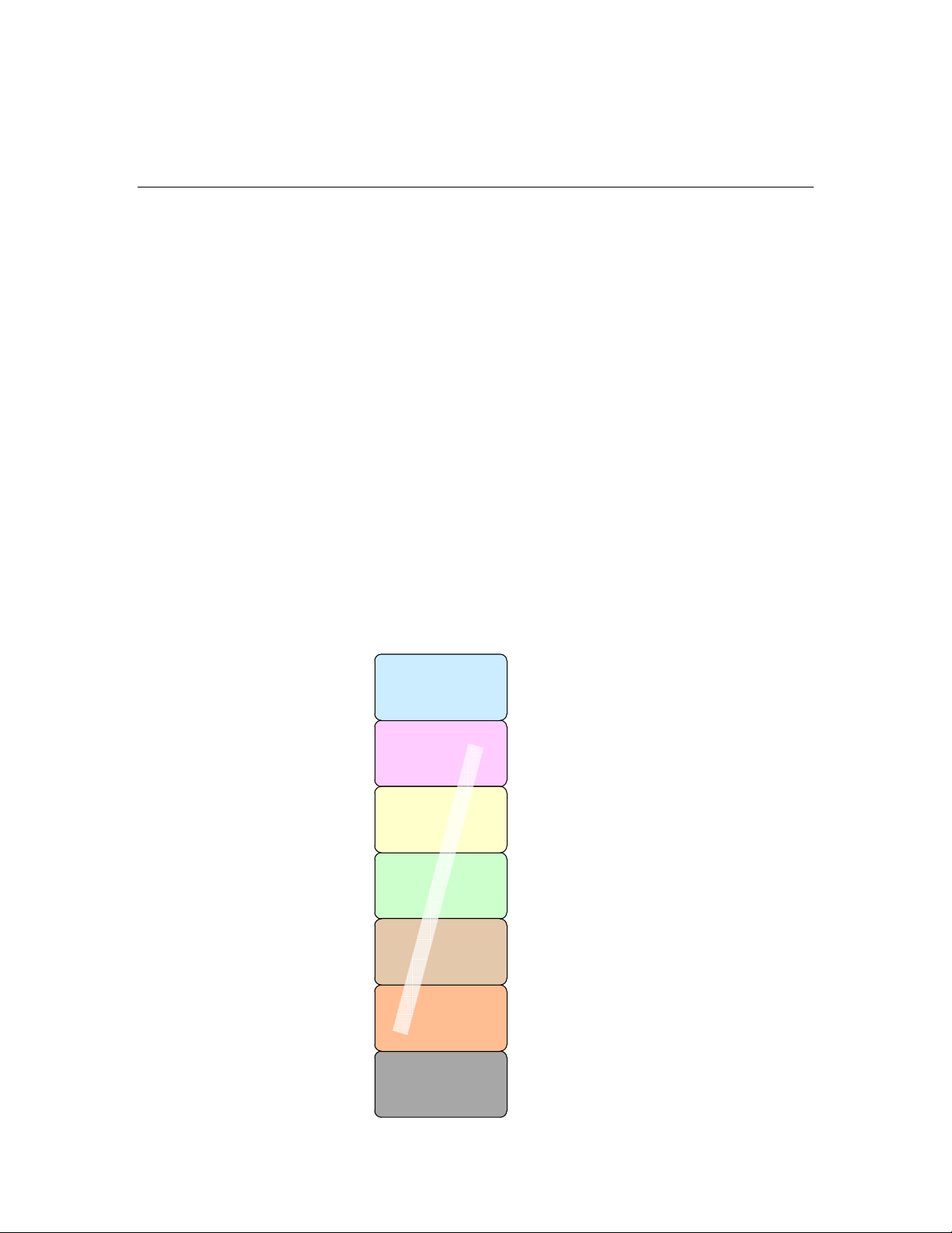
protocol on a single Neuron Chip or Echelon Smart Transceiver.
Traditional single-chip approach
(Neuron Chip or Smart Transceiver)
Application layer
Presentation layer
Session layer
Transport layer
Network layer
Data link layer
Neuron C
Application
(NodeBuilder FX,
Mini Kit)
re
wa
m
r
i
F
n
o
r
u
e
N
Physical layer
Transceiver and
wiring
LonTalk Stack Developer’s Guide 3
Page 16

A L
ONWORKS device that uses a single processor chip is called a Neuron-hosted
device, which means that the Neuron-based processor (the Echelon Smart
Transceiver) runs both the application and the LonTalk protocol.
For a Neuron-hosted device that uses a Neuron Chip or Echelon Smart
Transceiver, the physical layer (layer 1) is handled by the Neuron Chip or
Echelon Smart Transceiver. The middle layers (layers 2 through 6) are handled
by the Neuron firmware. The application layer (layer 7) is handled by your
Neuron C application program. You can create the application program using the
Neuron C programming language in either the NodeBuilder
Tool or the Mini FX.
®
FX Development
A LONWORKS Device with Two Processor Chips
Some LONWORKS devices run applications that require more memory or
processing capabilities than a single Neuron Chip or Echelon Smart Transceiver
can provide. Other L
to an existing processor and application. For these applications, the device uses
two processor chips working together:
• An Echelon Smart Transceiver or Neuron Chip.
• A microprocessor, microcontroller, or embedded processor. This is
typically called the host processor.
ONWORKS device that uses two processor chips is called a host-based device,
A L
which means that the device includes an Echelon Smart Transceiver or Neuron
Chip plus a host processor.
ONWORKS devices are implemented by adding a transceiver
Compared to the single-chip device, the Echelon Smart Transceiver or Neuron
Chip implements only a subset of the LonTalk protocol layers. The host
processor implements the remaining layers and runs the device’s application
program. The Echelon Smart Transceiver or Neuron Chip and the host processor
communicate with each other through a link-layer interface.
For a single-chip, Neuron-hosted, device you write the application program in
Neuron C. For a host-based device, you write the application program in ANSI C,
C++, or other high-level language, using a common application framework and
application programming interface (API). This API is called the LonTalk API. In
addition, for a host-based device, you select a suitable host processor and use the
host processor’s application development environment, rather than the
NodeBuilder FX Development Tool or the Mini FX application, to develop the
application.
Echelon provides the following solutions for creating host-based L
devices:
• ShortStack Developer’s Kit
• LonTalk Stack Developer’s Kit
ONWORKS
ShortStack Developer’s Kit
The ShortStack Developer’s Kit is a set of development tools, APIs, and firmware
for developing host-based L
and a ShortStack Micro Server.
ONWORKS devices that use the LonTalk Compact API
4 Introduction to the LonTalk Stack
Page 17
A ShortStack Micro Server is an Echelon Smart Transceiver or Neuron Chip with
ShortStack firmware that implements layers 2 to 5 (and part of layer 6) of the
LonTalk protocol. The host processor implements the application layer (layer 7)
and part of the presentation layer (layer 6). The Echelon Smart Transceiver or
Neuron Chip provides the physical interface for the L
ONWORKS communications
channel. The ShortStack firmware allows you to use almost any host processor
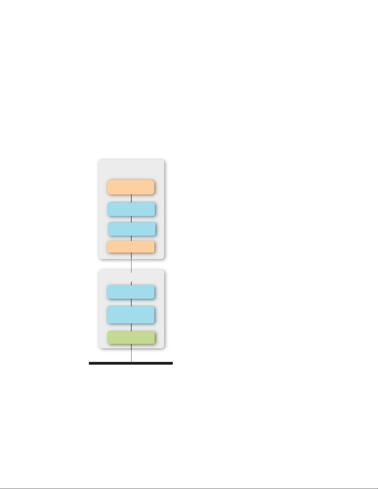
for your device’s application and I/O. The following figure displays the
ShortStack solution for a host-based L
ONWORKS device.
A simple serial communications interface provides communications between the
ShortStack Micro Server and the host processor. Because a ShortStack Micro
Server can work with any host processor, you must provide the serial driver
implementation, although Echelon does provide the serial driver API and an
example driver for some host processors. An example driver is available for an
®
Atmel
ARM7 microprocessor.
Host Processor
Application
LonTalk API
ISO/IEC 14908-1
Layer 7
Serial I/O Driver
Smart Transceiver
ShortStack
ISO/IEC 14908-1
Layers 2 – 6
ISO/IEC 14908-2 or 3
Layer 1 PHY
Communications Channel
For ShortStack device development, you use the C or C++ programming
language. Alternatively, you can develop ShortStack devices using any
programming language supported by the host processor if you port the LonTalk
Compact API and the application framework generated by the LonTalk Interface
Developer utility to that language.
You use the Echelon LonTalk Interface Developer (LID) utility to create the
application framework. Your application uses the Echelon LonTalk Compact
LonTalk Stack Developer’s Guide 5
Page 18
API, which is an ANSI C API, to manage communications with the ShortStack
Micro Server and devices on the L
ONWORKS network.
LonTalk Stack Developer’s Kit
The LonTalk Stack Developer’s Kit is a set of development tools, APIs, and
firmware for developing host-based L
Smart Transceiver or Neuron Chip, a Layer 2 Microprocessor Interface Program
(MIP), and the LonTalk API. You can also use the LonTalk Stack to create
controllers that are attached to IP-852 channels, and IP-852 routers that route
packets between IP-852 and native LonTalk channels.
The Echelon Smart Transceiver or Neuron Chip includes Neuron firmware that
implements the data link layer (layer 2) of the LonTalk protocol. The LonTalk
Stack provides a Layer 2 MIP that transforms the Echelon Smart Transceiver or
Neuron Chip into a network interface that can transmit and receive any packet
from the host processor. The LonTalk Stack includes source code that
implements layers 3 to 6 and part of layer 7 of the LonTalk protocol that you port
to your host processor. The LonTalk Stack also includes a LonTalk API
implementation that you port to your host processor that you integrate with your
application. This solution enables you to develop high-performance controllers
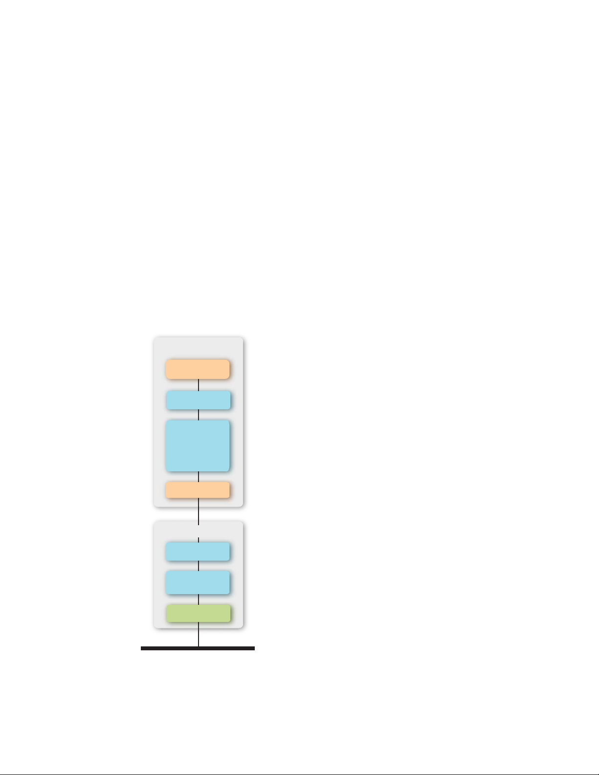
with up to 4,096 network variables and 32,767 address table entries.
Host Processor
ONWORKS devices that use the Echelon
Application
LonTalk API
ISO/IEC 14908-1
Layers 3 – 7
With ECS
Serial I/O Driver
Smart Transceiver
Layer 2 MIP
ISO/IEC 14908-1
Layer 2
ISO/IEC 14908-2 or 3
Layer 1 PHY
Communications Channel
To develop the application for your host processor, you use a C or C++ compiler
that supports the embedded processor. You will use the Echelon LonTalk
Interface Developer utility to create the application framework, and then you can
6 Introduction to the LonTalk Stack
Page 19

develop your application using the Echelon LonTalk API to manage
communications between the LonTalk Host stack, Echelon Smart Transceiver or
Neuron Chip, and other L
The LonTalk Stack includes an example communications interface driver for the
serial link layer that manages communications between the LonTalk Host stack
within the host processor and the Echelon Smart Transceiver or Neuron Chip
with Layer 2 MIP. You need to include the physical implementation of the serial
link layer in your LonTalk Stack device design, and you need to create the
software implementation of the serial interface driver.
ONWORKS devices on the network.
Comparing Neuron-Hosted, ShortStack, and LonTalk
Stack Devices
The following table compares some of the key characteristics of the
Neuron-hosted and host-based solutions for L
ONWORKS devices.
Characteristic
Maximum
number of
network
variables
Maximum
number of aliases
Maximum
number of
addresses
Maximum
number of
dynamic network
variables
Maximum
number of receive
transaction
records
Neuron-Hosted
Solution
254 254
254 127
15 15 32767
0 0 4096
16 16 32767
ShortStack
FX
[1]
4096
[2]
8192
LonTalk Stack
Maximum
number of
transmit
transaction
records
Support for the
LonTalk
Extended
Command Set
LonTalk Stack Developer’s Guide 7
2 2 32767
[3]
No No Yes
Page 20

File access
methods
supported
FTP
[4]
, DMF FTP
[4]
, DMF FTP
[4]
, DMF
[5]
Link-layer type N/A 4- or 5-line
SCI
or
6- or 7-line SPI
Typical host API
runtime footprint
N/A 5-6 KB code
with 1 KB
RAM (includes
serial driver,
but does not
include
optional API
or ISI API)
2-line SCI
Native LonTalk
protocol stack.
Includes LonTalk
API, Linux Serial
MIP driver, and the
SimpleDevice
example application.
IP-852 LonTalk
protocol stack.
Includes LonTalk
API, Linux Serial
MIP driver, and the
SimpleIp852Device
example application.
Native LonTalk to
IP-852 Router.
850 KB
955 KB
965 KB
Host processor
type
Application
development
language
N/A Any 8-, 16-,
32-, or 64-bit
microprocessor
or
microcontroller
Neuron C Any (typically
ANSI C)
Includes Linux Serial
MIP driver, and the
Ip852Router example
application.
Any 32- or 64-bit microprocessor or
microcontroller
ANSI C or C++ for the embedded
processor
8 Introduction to the LonTalk Stack
Page 21

Notes:
1. ShortStack Micro Servers running on FT 3150 or PL 3150 Echelon Smart
Transceivers support up to 254 network variables. ShortStack Micro Servers
running on FT 3120 Echelon Smart Transceivers support up to 240 network
variables, and ShortStack Micro Servers running on PL 3120 Echelon Smart
Transceivers support up to 62 network variables. A custom Micro Server can
support up to 254 network variables, depending on available resources.
2. ShortStack Micro Servers running on FT 3150 or PL 3150 Echelon Smart
Transceivers support up to 127 aliases. ShortStack Micro Servers running on FT
3120 Echelon Smart Transceivers support up to 120 aliases. ShortStack Micro
Servers running on PL 3120 Echelon Smart Transceivers support up to 62 aliases.
A custom Micro Server can support up to 127 aliases, depending on available
resources.
3. See the ISO/IEC 14908-1 Control Network Protocol Specification for more
information about the extended command set (ECS) network management
commands. This document is available from ISO:
www.iso.org/iso/home/store/catalogue_tc/catalogue_detail.htm?csnumber=60203
4. An implementation of the L
with the product.
5. For more information about the direct memory files (DMF) feature, see
Memory Files.
ONWORKS file transfer protocol (FTP) is not provided
Using Direct
The LonTalk Stack solution provides support for any host processor with the
highest performance and highest network capacity, and it can be used on native
ONWORKS and IP-852 channels. The ShortStack solution provides support for
L
any host processor, and supports TP/FT-10 and PL-20 channels. The ShortStack
solution supports fewer network variables and aliases that the LonTalk Stack
solution.
Requirements and Restrictions for LonTalk Stack
The LonTalk Stack requires that the application on the host processor use either
an embedded operating system or software that implements a minimum set of
operating system services.
The LonTalk Stack require about 850 KB of program memory on the host
processor, not including the application program or the operating system. In
addition, you must provide sufficient additional non-volatile memory for device
configuration data and any non-volatile data that you include in your application.
You can implement configuration properties as configuration network variables
or in configuration files. To access configuration files, you can implement the
ONWORKS file transfer protocol (FTP) or use the direct memory files (DMF)
L
feature. See
FTP or the DMF feature.
Using Direct Memory Files for more information about when to use
LonTalk Stack Developer’s Guide 9
Page 22

Development Tools for LonTalk Stack
To develop an application for a device that uses the LonTalk Stack, you need a
development system for the host processor. In addition, you need the LonTalk
Stack Developer’s Kit, which includes:
• LonTalk API
• LonTalk Host Stack
• LonTalk
LonTalk Stack device and generating the application framework
• Example LonTalk Stack applications
If you are not using an FT 5000 Smart Transceiver with serial interface to your
host, you will also need a NodeBuilder FX Development Tool or Mini FX
Evaluation Kit to develop the MIP image for your network interface.
You also need a network management tool to install and test your LonTalk Stack
device. You can use the OpenLNS Commissioning Tool, or any other tool that
can install and monitor L
Tool User’s Guide for more information on the OpenLNS Commissioning Tool.
You can use NodeBuilder Code Wizard that is included with the NodeBuilder FX
tool, version 3 or later, to help develop your Neuron C model file. The model file
is used to define the device’s interoperable interface.
Interface Developer utility for defining the interface for your
ONWORKS devices. See the OpenLNS Commissioning
LonTalk Stack Architecture
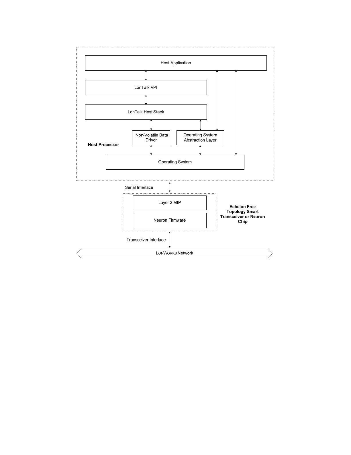
A LonTalk Stack device consists of the following components:
• Echelon Smart Transceiver or Neuron Chip with a Layer 2 MIP.
• A microprocessor, microcontroller, or embedded processor running the
following software:
• Host application that uses the LonTalk API.
• LonTalk API
• LonTalk host stack.
• Non-volatile data (NVD) driver.
• Operating system abstraction layer (OSAL).
• Embedded operating system.
• Serial I/O driver.
The following figure shows the basic architecture of a LonTalk Stack device.
10 Introduction to the LonTalk Stack
Page 23
The LonTalk Stack includes source code for the LonTalk API and the LonTalk
host stack. The kit also includes source code for additional operating system and
hardware APIs that you compile and link with your application. The LonTalk
API defines the functions that your application calls to communicate with other
devices on a L
the host application.
The LonTalk API consists of the following types of functions:
• Functions to initialize the host device after each reset.
• A function that the application must call periodically. This function
• Various functions to initiate typical operations, such as the propagation
• Event handler functions to notify the application of events, such as the
• Functions to interface with the operating system.
ONWORKS network. The API code provides ANSI C interfaces for
processes messages pending in any of the data queues.
of network variable updates.
arrival of network variable data or an error in the propagation of an
application message.
LonTalk Stack Developer’s Guide 11
Page 24

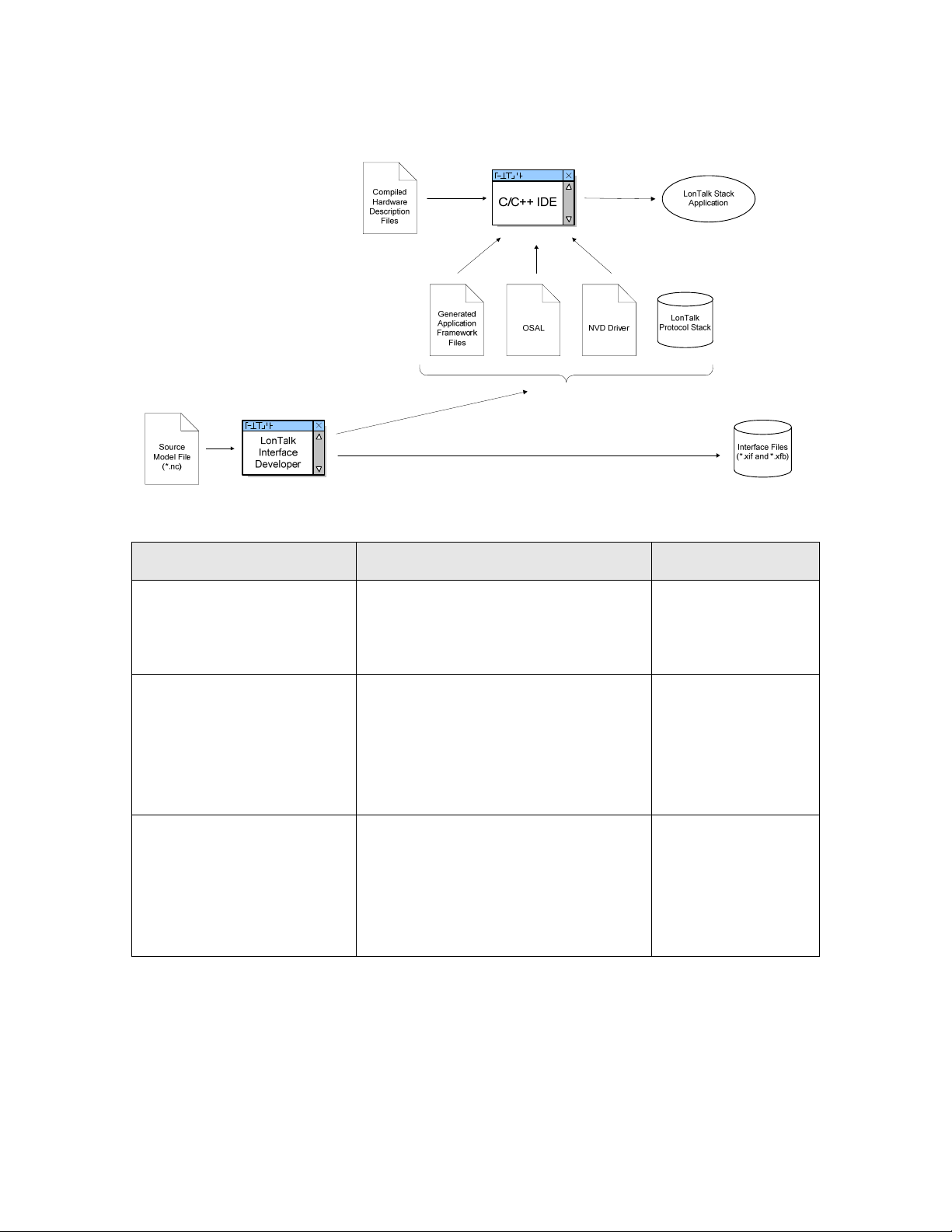
Overview of the LonTalk Stack Development Process
The development process for a LonTalk Stack application includes the following
steps:
1. Load the Neuron firmware and the Layer 2 MIP on the Echelon Smart
Transceiver or Neuron Chip.
2. Create the serial I/O hardware interface between your host processor and
the Echelon Smart Transceiver or Neuron Chip.
3. Develop a LonTalk Stack serial driver for your host processor that
manages the handshaking and data transfers between the host processor
and the Echelon Smart Transceiver or Neuron Chip.
4. Create a model file that defines the interoperable interface of your
LonTalk Stack device, including its network inputs and outputs.
5. Use the LonTalk Interface Developer utility to generate application
framework files and interface files from the model file.
6. Use a C/C++ development tool to create the LonTalk Stack application,
with input from:
• The application framework files generated by the LonTalk Interface
Developer utility
• The operating system abstraction layer (OSAL) files, which you might
need to modify
• The non-volatile data (NVD) driver files, which you might need to
modify
• The LonTalk host stack
• The LonTalk API
A LonTalk Stack device is comprised of both hardware and software components;
therefore, different people can be involved in the various steps, and these steps
can occur in parallel or sequentially. The figure does not imply a required order
of steps.
12 Introduction to the LonTalk Stack
Page 25
This manual describes the software development process for creating a LonTalk
Stack device, which includes the general tasks listed in the following table.
Task Additional Considerations Reference
Install the LonTalk
Developer’s Kit and become
familiar with it
Load an application image
file with the Neuron
firmware and Layer 2 MIP
onto an Echelon Smart
Transceiver or Neuron Chip.
Create the hardware
interface between your host
processor and the Echelon
Smart Transceiver or
Neuron Chip.
Chapter 2,
Getting
Started with the
LonTalk Stack
Developer’s Kit
Chapter 3,
Loading
the Echelon Smart
Transceiver or
Neuron Chip
Chapter 4,
Designing the Serial
I/O Hardware
Interface
LonTalk Stack Developer’s Guide 13
Page 26

Task Additional Considerations Reference
Develop a LonTalk Stack
serial driver for your host
processor that manages the
handshaking and data
transfers between the host
processor and the Echelon
Smart Transceiver or
Neuron Chip.
Select a microprocessor,
microcontroller, or
embedded processor.
Integrate the LonTalk Stack
application with your device
hardware
Chapter 5,
Creating
a LonTalk Stack
Serial Driver
The LonTalk Stack application runs
on any microprocessor,
microcontroller, or embedded
processor. You must meet the
LonTalk Stack hardware and software
requirements to ensure that the
LonTalk Stack device has sufficient
RAM and non-volatile memory.
You integrate the Echelon Smart
Transceiver or Neuron Chip with the
device hardware. You can reuse many
parts of a hardware design for
different applications to create
different LonTalk Stack devices.
Test and verify your
hardware design
Select and define the
functional profiles and
resource types for your
device using tools such as
the NodeBuilder Resource
Editor and the SNVT and
SCPT Master List
You must ensure that the host
processor and the Echelon Smart
Transceiver or Neuron Chip can
communicate using the serial
interface.
You must select profiles and types for
use in the device’s interoperable
interface for each application that you
plan to implement. This selection can
include the definition of user-defined
types for network variables,
configuration properties or functional
profiles. A large set of standard
definitions is also available and is
sufficient for many applications.
Chapter 6,
Creating
a Model File
14 Introduction to the LonTalk Stack
Page 27

Task Additional Considerations Reference
Structure the layout and
interoperable interface of
your LonTalk Stack device
by creating a model file
Use the LonTalk Interface
Developer utility to generate
device interface data, device
interface files, and a
skeleton application
framework
You must define the interoperable
interface for your device in a model
file, using the Neuron C (Version 2.1)
language, for every application that
you implement. You can write this
code by hand, derive it from an
existing Neuron C application, or use
the NodeBuilder Code Wizard
included with the NodeBuilder
Development Tool to create the
required code using a graphical user
interface.
You must execute this utility, a simple
click-through wizard, whenever the
model file changes or other
preferences change. The utility
generates the interface files (including
the XIF file) and source code that you
can compile and link with your
application. This source code includes
data that is required for initialization
and for complete implementations of
some aspects of your device.
Chapter 6,
Creating
a Model File
Appendix C,
Neuron
C Syntax for the
Model File
Chapter 7,
Using the
LonTalk Interface
Developer Utility
Complete the LonTalk API
event handler functions and
callback handler functions to
process application-specific
ONWORKS events
L
Modify the Operating
System Abstraction Layer
(OSAL) files for your
application’s operating
system
Modify the non-volatile data
(NVD) driver files
You must complete the event handler
functions and callback handler
functions for every application that
you implement, because they provide
input from network events to your
application, and because they are part
of your networked device’s control
algorithm.
Depending on the type of non-volatile
memory that your device uses, you
can use one of the non-volatile data
drivers provided with the LonTalk
Stack, make minor modifications to
one of these drivers, or implement
your own driver.
Chapter 8,
Developing a
LonTalk Stack
Device Application
Appendix D,
LonTalk API
Integrating the
Application with an
Operating System in
Chapter 8,
Developing a
LonTalk Stack
Device Application
Providing Persistent
Storage for
Non-Volatile Data in
Chapter 8,
Developing a
LonTalk Stack
Device Application
LonTalk Stack Developer’s Guide 15
Page 28

Task Additional Considerations Reference
Modify your application to
interface with a L
ONWORKS
network by using the
LonTalk API function calls
Test, install, and integrate
your LonTalk Stack device
using a L
ONWORKS network
tool such as the OpenLNS
Commissioning Tool
You must make these function calls
for every application that you
implement. These calls include, for
example, calls to the
LonPropagateNv() function that
propagates an updated network
variable value to the network.
Together with the completion of the
Chapter 8,
Developing a
LonTalk Stack
Device Application
Appendix D,
LonTalk API
event and callback handler functions,
this task forms the core of your
networked device’s control algorithm.
OpenLNS
Commissioning Tool
User’s Guide
16 Introduction to the LonTalk Stack
Page 29

LonTalk Stack Developer’s Guide 17
Page 30

Page 31

2
Getting Started with the
LonTalk Stack Developer’s Kit
This chapter describes the LonTalk Stack and how to install it.
LonTalk Stack Developer’s Guide 19
Page 32

LonTalk Stack Overview
The LonTalk Stack Developer’s Kit contains the source code, firmware, and
documentation required to add a high-performance ISO/IEC 14908-1 control
networking interface to any smart device. The LonTalk Stack Developer’s Kit
includes the following components:
• C and C++ source code for the LonTalk host stack and LonTalk API
• Neuron image for a Layer 2 MIP for devices that use an FT 5000 for the
network interface
• Library with the Layer 2 MIP for devices that do not use an FT 5000 for
the network interface
• A set of example programs that demonstrate how to use the LonTalk API
to communicate with a L
• The LonTalk Interface Developer utility, which defines parameters for
your host application program and generates required device interface
data for your device
• Documentation, including this guide and HTML documentation for the
LonTalk API
ONWORKS network
Installing the LonTalk Stack Developer’s Kit
The following sections describe the hardware and software requirements, and
how to install the LonTalk Stack.
Note: The LonTalk Stack Developer’s Kit is not compatible with the FTXL
Developer’s Kit. You must uninstall the FTXL Developer’s Kit before installing
the LonTalk Stack Developer’s Kit on your computer.
Hardware Requirements
For the LonTalk Stack Developer’s Kit, your computer system must meet the
following minimum requirements:
• 1 gigahertz (GHz) or faster 32-bit (x86) or 64-bit (x64) processor
• 1 gigabyte (GB) RAM (32-bit) or 2 GB RAM (64-bit)
• 5 GB available hard disk space
In addition, you must have the following hardware for L
• L
ONWORKS compatible network interface, such as a U10 USB Network
Interface, SmartServer, or i.LON 600 IP-852 Router.
Software Requirements
For the LonTalk Stack, your computer system must meet one of the following
minimum requirements:
• Microsoft Windows 7 (32-bit or 64-bit).
ONWORKS connectivity:
• Microsoft Windows Vista.
20 Getting Started with the LonTalk Stack Developer’s Kit
Page 33

• Microsoft
®
Windows® XP, plus Service Pack 3 or later.
Installing the LonTalk Stack Developer’s Kit
To install the LonTalk Stack Developer’s Kit, perform the following steps:
1. Download and install the LonTalkStack200.exe file from the Echelon
Web site.
2. Follow the installation dialogs to install the LonTalk Stack Developer’s
Kit onto your computer.
In addition to the LonTalk Stack, the installation program also installs:
• L
ONMARK
• NodeBuilder Resource Editor
®
Resource Files
LonTalk Stack Files
The LonTalk host stack and LonTalk API are provided as portable ANSI C and
C++ files. These files are contained in the [LonTalkStack]\Source directory (the
LonTalk Stack Developer’s Kit typically installs the LonTalkStack directory in
the C:\LonWorks directory). The LonTalk Interface Developer utility
automatically copies these files from the LonTalkStack\Templates folder into
your project folder, but does not overwrite existing files with the same names.
The following table lists the files included in the LonTalk host stack and LonTalk
API. Many of the files are also used by the FTXL Developer’s Kit and therefore
have an FTXL prefix in their name.
File Name Description
FtxlApi.h Function definitions for the LonTalk API
FtxlHandlers.c
FtxlNvdFlashDirect.c
FtxlNvdFlashFs.c
FtxlNvdUserDefined.c
FtxlTypes.h C type definitions that are used by the LonTalk API
LonPlatform.h Definitions for adjusting your compiler and development
Function definitions for the event handler functions and
callback handler functions
Functions for managing non-volatile data
environment to the requirements of the LonTalk API
LonTalk Interface Developer
The LonTalk Interface Developer utility generates the device interface data and
device interface files required to implement the device interface for your LonTalk
Stack device. It also creates a skeleton application framework that you can
LonTalk Stack Developer’s Guide 21
Page 34

modify and link with your application. This framework contains most of the code
that is needed for initialization and other required processing.
The executable for the LonTalk Interface Developer utility is named LID.exe,
and is installed in the LonTalk Interface Developer directory (usually,
C:\LonWorks\InterfaceDeveloper).
The LonTalk Interface Developer utility also includes a command-line interface
that allows make-file and script-driven use of the utility. For more information
about the command-line interface, see Appendix A,
LonTalk Interface Developer
Command Line Usage.
For more information about the LonTalk Interface Developer utility, see Chapter
Using the LonTalk Interface Developer Utility.
7,
Example LonTalk Stack Applications
The LonTalk Stack Developer’s Kit includes three example applications that are
stored in the LonWorks\LonTalkStack\Examples directory. You can build
these example applications with Microsoft Visual Studio 2008, and then run
them on Windows. To run the examples, you must install OpenLDV 4.0, which
you can download for free from the Echelon Web site at
www.echelon.com/support/downloads. The following table describes these three
example applications:
Function Description
SimpleLtDevice Simulates a voltage amplifier device. This device receives
an input voltage value, multiplies the value by 2, and
outputs the new value.
This simulated device connects to a native LonTalk
channel via OpenLDV 4.0 (or later), using a standard
ONWORKS network interface.
L
This example requires a Layer 2 network interface such
as the Echelon U10 USB Network Interface.
SimpleIp852Device Identical to the SimpleLtDevice example, but it
connects to an IP-852 channel rather than a native
ONWORKS channel.
L
This example requires the Echelon IP-852 Configuration
Server (you can download from this app for free from the
Echelon Web site at
www.echelon.com/support/downloads).
Ip852Router A router that connects an IP-852 channel to a native
ONWORKS channel.
L
This example uses OpenLDV 4.0 (or later) and a standard
Layer 2 LONWORKS network interface to communicate
with the native L
ONWORKS channel (for example, U10
USB network interface or PCC-10, PCLTA-20, or
PCLTA-21 network interface card).
22 Getting Started with the LonTalk Stack Developer’s Kit
Page 35

See Appendix G,
about these examples.
Example LonTalk Stack Applications, for more information
LonTalk Stack Developer’s Guide 23
Page 36

24 Getting Started with the LonTalk Stack Developer’s Kit
Page 37

3
Loading the Echelon Smart
Transceiver or Neuron Chip
This chapter describes how to load an application image
with the Neuron firmware and Layer 2 MIP onto an Echelon
Smart Transceiver or Neuron Chip.
LonTalk Stack Developer’s Guide 25
Page 38

Loading Overview
To create a LonTalk Stack device, you first need to load an Echelon Smart
Transceiver or Neuron Chip with an application image file. The application
image contains Neuron firmware that implements the data link layer of the
LonTalk protocol (layer 2), and a Layer 2 MIP that enables the Echelon Smart
Transceiver or Neuron Chip to transmit and receive any packet to and from the
host processor.
You can load the Echelon Smart Transceiver or Neuron Chip using one of the
following three options:
1. Load an Echelon-provided pre-compiled application image file onto an
Echelon FT 5000 Smart Transceiver or PL 3120 Smart Transceiver.
• The FT 5000 Smart Transceiver must be running Neuron Firmware
Version 19, using a 20 MHz clock speed, and be attached to a
TP/FT-10 channel.
• The PL 3120 Chip must be running Neuron Firmware Version 14 and
be attached to a PL-20 channel.
The application images files are stored in the
LonWorks\LonTalkStack\Source\Target\Neuron\SMIP directory.
This folder includes .NME and .NDL files for the FT 5000 Smart
Transceiver (SMIP FT5000.NME or SMIP FT5000.NDL) and the PL
3120 Smart Transceiver (SMIP PL3100.NME or SMIP PL3100.NDL)
You can program the .NME file directly on the serial EEPROM of the FT
5000 Smart Transceiver. You can load the .NDL file on the FT 5000
Smart Transceiver or PL 3120 Smart Transceiver using OpenLNS
Commissioning Tool or the NodeLoad utility.
2. Create your own application image with the NodeBuilder FX
Development Tool or the Mini FX Evaluation Kit and load it onto a FT
5000 Echelon Smart Transceiver, Series 5000 chip, or Neuron 3120E4
Chip with the appropriate programming tool. For more information on
the NodeBuilder tool and the Mini kit, go the Echelon Web site at
www.echelon.com/products/tools/development.
In this scenario, you create your own Neuron C application that specifies
the baud rate and the network buffering for the Echelon Smart
Transceiver or Neuron Chip. Specify a baud rate of 115,200 to make your
Echelon Smart Transceiver compatible with the provided Serial MIP
driver example. If you use a different baud rate, update the baud rate in
the Serial MIP driver example to make it compatible with your Echelon
Smart Transceiver.
You then generate an application image that includes your Neuron C
application and the Layer 2 MIP library (smip_ft5000.lib or
smip_pl3100.lib), and load the application image onto the Echelon
Smart Transceiver or Neuron Chip. The LonTalk Stack Developer’s Kit
includes a Neuron C application example that can be used to build the
SMIP (SMIP PDT.NC).
26 Loading the Echelon Smart Transceiver or Neuron Chip
Page 39

The following table lists the Neuron processor and memory combinations,
and it lists the application image files and tools that you use to program
each onto an Echelon Smart Transceiver or Neuron Chip
Echelon
Smart
Transceiver
Neuron
3120E4 Chip
FT 5000
Echelon
Smart
Transceiver
Memory
Type
On-chip
EEPROM
Off-chip
EEPROM
(minimum
4K) or
flash.
Image File
Extension
APB, NDL,
or NEI
Programming
Tool
Network
management
tool
NFI PROM
programmer
APB or
NDL
Network
management
tool
NME or
NMF
EEPROM or
flash
programmer
Example
Programming
Tools
NodeLoad utility
OpenLNS CT
A universal
programmer, such
as one from BPM
Microsystems or
HiLo Systems
NodeLoad utility
OpenLNS CT
A universal
programmer, such
as one from BPM
Microsystems or
HiLo Systems
In-circuit
programmer, such
as Total Phase™
Aardvark™
I2C/SPI Host
Adapter
Notes:
• Information about the NodeLoad utility and OpenLNS CT is available
www.echelon.com.
from
• Information about BPM Microsystems programmer models is available
www.bpmicro.com. The Forced Programming option in the menu is
from
provided only to refresh the internal memory contents and should not be
used to program new devices. In this mode, the programmer simply
reads out the contents of the memory and rewrites them.
• Information about HiLo Systems manual programmer models is available
www.hilosystems.com.tw.
from
• Information about TotalPhase programmers is available from
www.totalphase.com.
LonTalk Stack Developer’s Guide 27
Page 40

Notes:
• If you load an NDL file with the NodeLoad Utility, the last step of the
process may generate errors when the final network management
status checks are performed.
• To prevent link errors, you need to copy an updated symbol file to the
appropriate Neuron firmware folder on your development computer,
and then specify them as custom system images in the Hardware
Template Editor. This file has additional symbols for low-level serial
interrupt modifications, and access to the network buffer queues.
The following table lists where the updated symbol files are stored for
the FT 5000 Smart Transceiver and the PL 3120 Smart Transceiver,
and to where they need to be copied on your development computer.
Echelon Smart
Transceiver
PL 3120 Smart
Transceiver
FT 5000 Smart
Transceiver
• Before you load an application image onto the Echelon Smart
Transceiver or Neuron Chip, you must reset the node and hold the
service pin low for 5 seconds to put the node into the application-less
state.
Alternatively, your host application can send the niMODE_L5 local
network interface command to the Layer 2 MIP to switch it to Layer 5
mode. The Layer 2 MIP can then process most network management
commands so that a network loader can load the application image.
3. The same as option 2, but you also develop code that implements the
network interface with your host processor. See the next section,
Integrating a Custom Network Interface, for more information.
Updated Symbol File
Source/Target/Neuron/
Ver14/ b3120E4Xl2smip.sym
Source/Target/Neuron/
Ver19/bft5000l2smip.sym
Destination Folder on
Development Computer
C:/LonWorks/Images/Ver19
C:/LonWorks/Images/Ver14
Integrating a Custom Network Interface
You can create your own network interface and integrate it with your host
processor. The following sections describe the APIs included in the l2mlib.h file
that you can use to create a custom network interface.
Before creating your network interface, you need to copy two additional updated
symbol files to the Version 14 Neuron firmware folder on your development
computer, and then specify them as custom system images in the Hardware
Template Editor. The following table lists where the updated symbol files are
stored, and to where they need to be copied on your development computer.
28 Loading the Echelon Smart Transceiver or Neuron Chip
Page 41

Updated Symbol File
Destination Folder on
Development Computer
Source/Target/Neuron/L2ML
IB/ Ver14/sys3150l2mlib.sym
Source/Target/Neuron/L2ML
IB/ Ver14/sys3150l2mlib.nx
C:/LonWorks/Images/Ver14
C:/LonWorks/Images/Ver14
Defining Incoming Layer 2 Packet Buffers
You can define incoming Layer 2 packet buffers using the following syntax:
[length] [miCOMM|miINCOMINGL2] [backlog/altpath] NPDU [CRC_HI]
[CRC_LO]
The length field includes the 2 bytes before the NPDU, the NPDU itself, and the
two CRC bytes.
Functions
The following table describes the functions included in the l2mlib.h file that you
can use to create a custom network interface.
Function Syntax Description
l2ml_gol2()
extern system far void
l2ml_gol2(void);
Switches the network
processing to L2 mode. If it
is already in L2 mode, this
method does nothing. You
can return to the scheduler
when in L2 mode as the
network processor believes
there is no incoming traffic.
l2ml_gol5()
l2ml_getl2packet()
LonTalk Stack Developer’s Guide 29
extern system far void
l2ml_gol5(void);
extern system far
unsigned
*l2ml_getl2packet(void);
Switches the network
processing to L5 mode. If it
is already in L5 mode, this
method does nothing.
Returns any L2 packet
buffers in the receive queue.
This method returns NULL
if there are no L2 packet
buffers available.
Page 42

Function Syntax Description
l2ml_freel2packet()
l2ml_allocl2buffer()
l2ml_sendl2packet()
extern system far void
l2ml_freel2packet(unsigne
d *mp);
extern system far
unsigned
*l2ml_allocl2buffer(void)
;
The length field indicates the
size of the packet buffer
(including overhead).
The miCOMM field is
[miCOMM|miTQ] 0x12.
The format of this buffer is
[length] [miCOMM|miTQ]
[backlog/altpath] NPDU.
extern system far void
l2ml_sendl2packet(unsigne
d *mp);
Frees any packet buffers
returned by
l2ml_getl2packet()
method. This method does
not check for NULL
pointers. You can only free
packet buffers after
processing.
Allocates a L2 packet buffer
for transmitting. This
method returns NULL if
there are no L2 packet
buffers available.
Queues the packet buffer
allocated by
l2ml_allocl2buffer()
method for transmission.
This method does not check
for NULL pointers.
l2ml_l2buffsize()
extern system far
unsigned
l2ml_l2txbuffsize(void);
Returns the largest possible
size that the NPDU can be
for transmission to a
like-sized device (same
network input buffer size).
This is a better
measurement than the size
passed in from
l2ml_allocl2buffer()
method because it accounts
for internal overhead and
the receiver's capabilities
30 Loading the Echelon Smart Transceiver or Neuron Chip
Page 43

4
Designing the Serial I/O
Hardware Interface
This chapter describes what you need to design the serial
I/O hardware interface between your host processor and the
Echelon Smart Transceiver or Neuron Chip for devices that
use the Serial MIP.
LonTalk Stack Developer’s Guide 31
Page 44

Overview of the Hardware Interface
This chapter describes the hardware interface, including the requirement for
pull-up resistors, selecting a minimum communications interface bit rate,
considerations for host latency, specifying the SCI interface, and how to perform
an initial health check of the Echelon Smart Transceiver.
Reliability
The LonTalk Stack link layer protocol assumes a reliable serial link and does not
include error detection or error recovery. Instead, error detection and recovery
are implemented by the LonTalk protocol, and this protocol detects and recovers
from errors.
To minimize possible link-layer errors, be sure to design the hardware interface
for reliable and robust operations. For example, use a star-ground configuration
for your device layout on the device’s printed circuit board (PCB), limit entry
points for electrostatic discharge (ESD) current, provide ground guarding for
switching power supply control loops, provide good decoupling for V
maintain separation between digital circuitry and cabling for the network and
power. See the FT 3120 / FT 3150 Echelon Smart Transceiver Data Book, the PL
3120 / PL 3150 / PL 3170 Power Line Echelon Smart Transceiver Data Book, or
the Series 5000 Chip Data Book for more information about PCB design
considerations for an Echelon Smart Transceiver.
The example applications contain example implementations of the link layer
driver, including examples and recommendations for time-out guards within the
various states of that driver.
inputs, and
DD
Serial Communication Lines
For the SCI serial interfaces, you must add 10 kΩ pull-up resistors to the two
communication lines between the host processor and the Echelon Smart
Transceiver or Neuron Chip. These pull-up resistors prevent invalid transactions
on start-up and reset of the host processor or the Echelon Smart Transceiver or
Neuron Chip. Without a pull-up resistor, certain I/O pins can revert to a floating
state during start-up, which can cause unpredictable results.
High-speed communication lines should also include proper back termination.
Place a series resistor with a value equal to the characteristic impedance (Z
the PCB trace minus the output impedance of the driving gate (the resistor value
should be approximately 50 Ω) at the driving pin. In addition, the trace should
run on the top layer of the PCB, over the inner ground plane, and should not
have any vias to the other side of the PCB. Low-impedance routing and correct
line termination is increasingly important with higher link layer bit rates, so
carefully check the signal quality for both the Echelon Smart Transceiver or
Neuron Chip and the host when you design and test new LonTalk Stack device
hardware, or when you change the link-layer parameters for existing LonTalk
Stack device hardware.
) of
0
32 Designing the Serial I/O Hardware Interface
Page 45

The RESET~ Pin
The Echelon Smart Transceiver and Neuron Chip have no special requirements
for the RESET~ (or RST~) pin. See the FT 3120 / FT 3150 Echelon Smart
Transceiver Data Book, the PL 3120 / PL 3150 / PL 3170 Power Line Echelon
Smart Transceiver Data Book, or the Series 5000 Chip Data Book for information
about the requirements for this pin.
However, because a LonTalk Stack device uses two processor chips, the Echelon
Smart Transceiver or Neuron Chip and the host processor, you have an
additional consideration for the RESET~ pin: Whether to connect the host
processor’s reset pin to the Echelon Smart Transceiver or Neuron Chip RESET~
pin.
For most LonTalk Stack devices, you should not connect the two reset pins to
each other. It is usually better for the Echelon Smart Transceiver or Neuron
Chip and the host application to be able to reset independently. For example,
when the Echelon Smart Transceiver or Neuron Chip encounters an error that
causes a reset, it logs the reset cause (see
processor resets the Echelon Smart Transceiver or Neuron Chip directly, possibly
before the Echelon Smart Transceiver or Neuron Chip can detect and log the
error, your application cannot query the Echelon Smart Transceiver or Neuron
Chip error log after the reset to identify the problem that caused the reset. The
Echelon Smart Transceiver or Neuron Chip also resets as part of the normal
process of integrating the device within a network; there is normally no need for
the host application to reset at the same time.
Querying the Error Log); if the host
In addition, the host processor should not reset the Echelon Smart Transceiver or
Neuron Chip while it is starting up (that is, before it sends the
LonResetNotification uplink reset message to the host processor).
For devices that require the host application to be able to control all operating
parameters of the Echelon Smart Transceiver or Neuron Chip, including reset,
you can connect one of the host processor’s general-purpose I/O (GPIO) output
pins to the Echelon Smart Transceiver or Neuron Chip RESET~ pin, and drive
the GPIO pin to cause an Echelon Smart Transceiver or Neuron Chip reset from
within your application or within your serial driver. Alternatively, you can
connect one of the host processor’s GPIO input pins to the Echelon Smart
Transceiver or Neuron Chip RESET~ pin so that the host application can be
informed of Echelon Smart Transceiver or Neuron Chip resets.
A host processor’s GPIO output pin should not actively drive the Echelon Smart
Transceiver’s RESET~ pin high, but instead should drive the pin low. You can
use one of the following methods to ensure that the GPIO pin cannot drive the
RESET~ pin high:
• Ensure that the GPIO pin is configured as an open-drain (open-collector)
output
• Ensure that the GPIO pin is configured as a tri-state output
• Place a Schottky diode between the GPIO pin and the RESET~ pin, with
the cathode end of the diode connected to the GPIO pin
Configuring the GPIO pin as either open drain or tri-state ensures that the GPIO
pin is in a high-impedance state until it is driven low. Using a Schottky diode is
preferable to using a regular diode because a Schottky diode has a low forward
voltage drop (typically, 0.15 to 0.45 V), whereas a regular diode has a much
LonTalk Stack Developer’s Guide 33
Page 46

higher voltage drop (typically, 0.7 V), that is, the Schottky diode ensures that the
(
)
+++
=
voltage drop is low enough to ensure a logic-low signal.
Host-driven reset of the Echelon Smart Transceiver or Neuron Chip should only
be an emergency means to recover from some serious error. In addition, the host
application or serial driver should always log the reason or cause for the reset,
along with timestamp information. An unrecoverable error that requires a reset
of the Echelon Smart Transceiver or Neuron Chip is generally evidence of a
malfunction in the host driver, the Echelon Smart Transceiver or Neuron Chip,
or the physical link layer, and should be investigated.
Selecting the Link-Layer Bit Rate
The serial link bit rate for the pre-built Layer 2 MIP images is fixed at 115, 200
bps. If you build a custom Layer 2 MIP image, you can specify a lower bit rate if
required for your hardware. The minimum bit rate for the serial link between
the Echelon Smart Transceiver or Neuron Chip and the host processor is most
directly determined by the expected number of packets per second, the type of
packets, and the size of the packets. Another factor that can significantly
influence the required bit rate is support for explicit addressing, an optional
feature that the LonTalk Stack application can enable and disable.
Recommendations: The following recommendations apply to general-use
ONWORKS devices:
L
• Echelon Smart Transceiver or Neuron Chip external clock frequency
o 10 MHz or higher for TP/FT-10 devices (for Series 5000 devices,
specify a minimum 5 MHz system clock rate)
o 5 MHz or higher for power-line devices
• Bit rate
o 38 400 bps or higher for TP/FT-10 devices
o 9600 bps or higher for power-line devices
To generate a more precise estimate for the minimum bit rate for the serial
interface, use the following formula:
Interfacesizetype
where:
• The constant 5 represents general communications overhead
•
•
is the packet-type overhead, and has one of the following values:
P
type
o 3 for network-variable messages
o 1 for application messages
EA is the explicit-addressing overhead, and has one of the following
values:
o 0 for no explicit-addressing support
**5 PPSBPTPEAPMinBitRate
exp
o 11 for explicit-addressing support enabled
•
P is the packet size of the payload, and has one of the following values:
size
34 Designing the Serial I/O Hardware Interface
Page 47

o sizeof(network_variable)
o sizeof(message_length)
•
BPT represents data transfer overhead for the serial interface, and
Interface
has one of the following values:
o 1 bit per transfer for SPI
o 10 bits per transfer for SCI
•
PPS is the expected packet-per-second throughput value
exp
Example: For an average network variable size of 3 bytes, no explicit messaging
support, and a TP/FT-10 channel that delivers up to 180 packets per second, the
minimum bit rate for an SCI interface is 19 200 bps. To allow for larger NVs,
channel noise, and other systemic latency, you should consider setting the device
bit rate at the next greater value above the minimum calculated from the
formula. Thus, for this example, a bit rate of 38 400 or 76 800 bps is
recommended.
To calculate the expected packet-per-second throughput value for a channel, you
can use the Echelon Perf utility, available from
www.echelon.com/downloads.
However, the bit rate is not the only factor that determines the link-layer transit
time. Some portion of the link-layer transit time is spent negotiating handshake
lines between the host and the Echelon Smart Transceiver. For faster bit rates,
the handshaking overhead can increase, thus your application might require a
faster clock speed for the Echelon Smart Transceiver to handle the extra
processing.
Example: For a Series 3100 Echelon Smart Transceiver running at 10 MHz and
an ARM7 host running at 20 MHz, the link-layer transit for a 4-byte network
variable fetch, the handshaking overhead can be as much as 22% of the total
link-layer transit time at 19 200 bps, and as much as 40% at 38 400 bps.
Even though a Series 3100 Echelon Smart Transceiver running at 5 MHz can be
sufficient for the demands of a power-line channel, a typical Echelon Smart
Transceiver operates at 10 MHz even when used exclusively with a power line
channel. The maximum clock rate for an Echelon Smart Transceiver based on a
PL 3120, PL 3150, or PL 3170 Echelon Smart Transceiver is 10 MHz.
For a performance test application that attempts to maximize the number of
propagated packets, the application is likely to show approximately 3% increased
throughput when operating with a 40 MHz Series 3100 Echelon Smart
Transceiver compared to a 10 MHz Series 3100 Echelon Smart Transceiver (for
FT 5000 Echelon Smart Transceivers, the comparison is between the 20 MHz
system clock setting and the 5 MHz system clock setting). However, for a
production application, which only occasionally transmits to the network and has
unused output buffers available on the Echelon Smart Transceiver, a faster
Echelon Smart Transceiver reduces the time required for the handshake
overhead (by up to a factor of 4 for Series 3100 devices – or up to a factor of 16 for
Series 5000 devices, compared to Series 3100 devices) so that a downlink packet
can be delivered to the Echelon Smart Transceiver more quickly, which can
improve overall application latency. Thus, depending on the needs of your
application, you can use a slower or faster Echelon Smart Transceiver.
LonTalk Stack Developer’s Guide 35
Page 48

Host Latency Considerations
()(
)
+++
=
The processing time required by the host processor for an Echelon Smart
Transceiver or Neuron Chip can have a significant impact on link-layer transit
time for network communications and on the total duration of network
transactions. This impact is the host latency for the LonTalk Stack application.
To maintain consistent network throughput, a host processor must complete each
transaction as quickly as possible. Operations that take a long time to complete,
such as flash memory writes, should be deferred whenever possible. For
example, an ARM7 host processor running at 20 MHz can respond to a
network-variable fetch request in less than 60 µs, but typically requires 10-12 ms
to erase and write a sector in flash memory.
The following formula shows the overall impact of host latency on total
transaction time:
*2
where:
•
t is the total transaction time
trans
•
t is the channel propagation time
channel
•
t is the Echelon Smart Transceiver or Neuron Chip latency
(approximately 1 ms for a Series 3100 Echelon Smart Transceiver
running at 10 MHz; approximately 65 µs for a FT 5000 Echelon Smart
Transceiver running with an 80 MHz system clock)
•
t
linklayer
t is the host latency
•
host
The channel propagation time and the Echelon Smart Transceiver latency are
fairly constant for each transaction. However, link-layer transit time and host
latency can be variable, depending on the design of the host application.
You must ensure that the total transaction time for any transaction is much less
than the L
timer for a TP/FT-10 channel is 64 ms, and the transmit timer for a PL-20
channel is 384 ms.
rMicroServe
is the link-layer transit time
ONWORKS network transmit timer. For example, the typical transmit
ttttt
hostlinklayerrMicroServechanneltrans
Typical host processors are fast enough to minimize link-layer transit time and
host latency, and to ensure that the total transaction time is sufficiently low.
Nonetheless, your application might benefit from using an asynchronous design
of the host serial driver and from deferring time-consuming operations such as
flash memory writes.
SCI Interface
The LonTalk Stack Serial Communications Interface (SCI) is an asynchronous
serial interface between the Echelon Smart Transceiver or Neuron Chip and the
host processor. The communications format is:
• 1 start bit
36 Designing the Serial I/O Hardware Interface
Page 49

• 8 data bits (least-significant bit first)
• 1 stop bit
The SCI link-layer interface uses two serial data lines: RXD (receive data) and
TXD (transmit data). The following diagram summarizes the two serial data
lines and their I/O pin assignments. The signal directions are from the point of
view of the Echelon Smart Transceiver. An uplink transaction describes data
exchange from the Echelon Smart Transceiver to the host processor, and uses the
TXD line. A downlink transaction refers to data exchange from host processor to
the Echelon Smart Transceiver, and uses the RXD line.
Performing an Initial Echelon Smart Transceiver Health Check
After you load the Layer 2 MIP image into an Echelon Smart Transceiver or
Neuron Chip, the Echelon Smart Transceiver or Neuron Chip enters quiet mode
(also known as flush mode). While the Echelon Smart Transceiver or Neuron
Chip is in quiet mode, all network communication is paused.
The Echelon Smart Transceiver or Neuron Chip enters quiet mode to ensure that
only complete implementations of the LonTalk protocol stack attach to a
ONWORKS network. In a functioning LonTalk Stack device, the application
L
initializes the Echelon Smart Transceiver or Neuron Chip. After that
initialization is complete, the Echelon Smart Transceiver or Neuron Chip leaves
quiet mode and enables regular network communication.
To check that the Echelon Smart Transceiver or Neuron Chip is functioning
correctly before the host processor has initialized it, you can use an oscilloscope
or a logic analyzer to observe the activity on the TXD (IO10) pin that reflects the
uplink LonNiReset message transfer that follows an Echelon Smart Transceiver
or Neuron Chip reset, as shown in the following figure.
LonTalk Stack Developer’s Guide 37
Page 50

Echelon Smart
Transceiver
PL 3120
FT 5000
Your hardware design should include a switch that connects the RESET~ pin to
ground; you press this switch to reset the Echelon Smart Transceiver or Neuron
Chip.
When you press the reset switch for a LonTalk Stack device, the Neuron
firmware performs reset processing, as described in the data books for the
Echelon Smart Transceiver and Neuron Chips. Then, the Echelon Smart
Transceiver or Neuron Chip performs reset processing that is generally
independent of the host processor.
9 x 10 kΩ
TXD
RXD
RESET~
V
DD
38 Designing the Serial I/O Hardware Interface
Page 51

5
Creating a LonTalk Stack Serial
MIP Driver
This chapter describes the link-layer protocol (LLP) and how
to develop a LonTalk Stack Serial MIP driver for your host
processor. This driver manages the handshaking and data
transfers between the host and the Echelon Smart
Transceiver or Neuron Chip. The driver also manages the
buffers in the host for communication with the Echelon
Smart Transceiver or Neuron Chip.
LonTalk Stack Developer’s Guide 39
Page 52

Overview of the Link Layer Protocol
The LonTalk Serial MIP driver communicates with the host processor over the
built-in SCI serial interface hardware of the FT 5000 Echelon Smart Transceiver,
Series 5000 chip, and the PL 3120 Echelon Smart Transceiver. The Serial MIP
driver uses the Serial MIP link-layer protocol (LLP), which is a two-signal serial
protocol with no extra requirements for handshake signals. The Serial MIP LLP
features quick recovery from serial communication errors such as dropped bytes
or corrupted serial frames.
Code Packet Layout
The basic component of the Serial MIP LLP is the code packet, which starts with
an escape code. If an escape code appears in a normal data stream it is followed
by another escape code and interpreted as a single data byte value rather than
the start of the code packet. The following figure illustrates the code packet
layout.
BYTE 0 BYTE 1 BYTE 2 BYTE 3
Escape:
0x7E
Sequence #,
ACK bit,
Param Data Packet
Checksum
Type Code
(excludes
0x7E)
Sequence
[D7-D5]
The second byte contains a 3-bit sequence number in the sequence bits (D5-D7), a
single ACK bit (D4), and a 4-bit Type Code bits (D0-D3). You cannot form the
escape code by combining a Type Code value with the sequence number (0x0E is
not allowed). As a result, you can create 15 different codes.
The sequence number is cycled through between values ‘1’ and ‘7’, with ‘0’ being
an initialization value. When a code packet is received that has the same
sequence number as the previous code packet received that packet (and any
following data) is rejected (this transfer will be acknowledged if necessary). The
exception is if the sequence number is zero. The zero sequence number may be
used for any idempotent code packet or message.
Ack
[D4]
Type Code
[D3-D0]
The third and fourth bytes may contain the escape code value, but they will not
interpreted as escape codes. This may cause minor re-synchronization issues if
this packet is broken; however, it ensures a constant code packet size.
40 Creating a LonTalk Stack Serial MIP Driver
Page 53

The packet sum is an 8-bit value that, when added to the first three bytes, results
in an 8-bit zero result.
The code packet hast the following features:
• Asynchronous method of presenting itself at any time (by using an escape
sequence).
• Checksum verification.
• Data transfer initiation.
• Duplication detection using a sequence number. Duplicates may be sent
when an expected response is lost or broken and does not occur within a
time-out period.
Data outside of the code packet is restricted to either a message or a multi-byte
local network interface command or response and is always enclosed with a length
byte in the front and a checksum at the end. The length byte does not account for
the checksum at the end—the inclusion of the checksum is implied. The
checksum covers the data that preceded it; therefore, it does include the length
byte.
Note: All data outside a code packet must include an escape prefix before any
escape data values. For example, if a 0x7E value appears in the sequence it must
be followed by another 0x7E (the first 0x7E value is the escape prefix).
Checksum bytes and length bytes must be preceded with escape prefixes.
The following table summarizes the layout of the data message used in Layer 5
mode and for the niNETMGMT local network interface command (Layer 2 mode
is required for the LonTalk Stack). When sending local network interface
commands (NI Commands other than the niCOMM or niNETMGMT) that have
additional data, the commands are contained in a data message and they are
preceded by a CpMsg code packet.
BYTE 0 BYTE 1 BYTE 2..N BYTE N+1
Length
(bytes to
follow
except
checksum)
NI
Command
SICB starting w/ message header Message
Checksum
of bytes 0-N
The following table summarizes the layout of the data message used in Layer 2
mode.
BYTE 0 BYTE 1 BYTE 2..N BYTE N+1
Length
(bytes to
follow
except
checksum)
NI
Command
Priority/AltPath/DeltaBacklog byte,
NPDU,
CRC (2 Bytes)
Message
Checksum
of bytes 0-N
LonTalk Stack Developer’s Guide 41
Page 54

Type Code Values
The following table lists the values for the Type Code byte. Uplink means that
data is transferred from the Echelon Smart Transceiver or Neuron Chip to the
host processor. Downlink mans that data is transferred from the host processor
to the Echelon Smart Transceiver or Neuron Chip.
Value Type Description Uplink /
Downlink
0 CpNull No data is being sent. Use this value for
acknowledge-only packets, or for pinging.
1 CpFail The previous transfer was broken or in
error. This is typically due to checksum
errors or fragmented transfers. The
correct response to this command is to
resend the previous transfer.
2 CpMsg One message follows. A message is any
multi-byte network interface transfer and
requires an application output buffer or
packet buffer in the downlink case. The
number of messages is stored in the
Param Data field.
This value is limited to one in both the
downlink and uplink case.
The message follows the code packet
checksum byte, and consists of a length
byte, the NI command, the message itself,
and a checksum.
U/D
U/D
U/D
3 CpMsgReq Optional. Sent by the host for requesting
both the attention of the Serial MIP and
requesting an uplink CpMsgAck.
The Param Data field contains either a 0
or a 1 informing the Serial MIP that the
following message is either a non-priority
message (0) or a priority message (1).
The MIP Serial driver does not use
priority messaging; therefore, this value
is ignored. This allows the Serial MIP to
respond to the CpMsgReq based on
actual buffer availability.
Alternatively, you can send the entire
CpMsg plus message to the MIP and a
CpMsgReject may be sent uplink if
there are no available buffers.
42 Creating a LonTalk Stack Serial MIP Driver
D
Page 55

Value Type Description Uplink /
Downlink
4 CpMsgAck The Serial MIP is entering the
ready-receive state. This is the Serial
MIP’s response to the CpMsgReq.
5 CpMsgReject An attempt to transfer a message
downlink is rejected because of a lack of
buffer space.
This code packet will be a response to a
downlink CpMsgReq code packet or a
response to a CpMsg without the
CpMsgReq being sent.
This code indicates that the offered
downlink traffic is more than the Serial
MIP can handle (it has no more APP or
NET output buffers).
Upon receiving this code, the device
driver should repeat the message send
process until it succeeds.
6 CpNiCmdShort Sends a single byte local network
interface command. The command is
stored in the Param Data field.
U
U
U/D
7 CpResync This command is sent by the host to start
a new session with the Serial MIP. When
received it will reset the transmit and
receive sequence numbers to zero so that
any subsequent sequence numbers will be
accepted rather than rejected.
This command is also a good way to
establish that communications are
functioning with the Serial MIP.
The Serial MIP always responds to this
command with a CpNull packet, so the
host can determine that the serial link is
not simply echoing data.
Notes:
• Use symmetrical timeouts on the host processor. There is an inter-byte
timeout on the client side of 40ms when receiving either a code packet or
a message body. There is a timeout of 250ms when waiting for the start
of a downlink message CpMsg following a CpMsgReq / CpMsgAck
sequence.
D
LonTalk Stack Developer’s Guide 43
Page 56

• All length fields do not count for escape prefixes. Instead, they reflect the
length of the real data stream above the link-layer protocol. All length
fields do not account for the checksum.
• Broken code packets (code packets with missing or corrupt bytes) are not
responded to at all, and they rely on time-out mechanisms for
re-transmission.
• Broken message streams are responded to as soon as the error condition
is observed. The response is the CpFail code packet.
Acknowledgment Rules
The Ack bit is used to send a success response to a previous transfer, specifically
transfers that send data that is above the LLP (non-LLP data). These are
transfers of messages and transfers of local network interface commands.
To reduce traffic, not all data transfers require acknowledgement. Following are
the acknowledgement rules:
• If a transfer requires an acknowledgment and there is no other data that
needs to be sent, a CpNull packet is sent with the Pass/Ack bit set.
Otherwise, if there is outgoing traffic to be sent the Ack bit will be
included in the following transfer. This is true for both uplink and
downlink data messages.
• Code packets that do not require an acknowledgment via the Ack bit are
packets that result in an immediate response anyway. The response
implies acknowledgment. The following table lists these types of code
packets:
Code Packet Description
CpMsgReq The Serial MIP will respond with either the
CpMsgAck, or a criss-cross could occur and an
unrelated code packet will be sent by the Serial
MIP.
CpMsgAck The host does not need to acknowledge this
message. Instead it provides an implied
acknowledgement by sending the CpMsg code
packet followed by a message packet
• Data that is sent and requires acknowledgement will persist in the source
until the acknowledgment is received. While the persistent data is
waiting for acknowledgement, the Acknowledge Wait timeout, which is
300ms for the Serial MIP and the driver, causes the persistent data to be
re-sent.
44 Creating a LonTalk Stack Serial MIP Driver
Page 57

Sequence Number Cycling and Duplicate Detection
The sequence number is used to reject duplicate non-LLP data. Duplicate LLP
data does not effect the LLP; therefore, the sequence number is only cycled for
each transfer of non-LLP data. For example, two consecutive CpMsgReq
packets have no effect—the second CpMsgReq packet reinstates the
ready-receive state and the CpMsgAck is re-sent.
Supported MIP Command Set
The following table lists the MIP commands you can use in your LonTalk Stack
Serial MIP driver.
Uplink local network interface commands that must also convey additional data
(for example, the niL2MODE response command) will always result in a data
message that is at least 3 bytes in length. This is because the host driver expects
at least 4 bytes of data (3 bytes plus checksum) to appear following a code packet.
Uplink means that data is transferred from the Echelon Smart Transceiver to the
host processor. Downlink mans that data is transferred from the host processor
to the Echelon Smart Transceiver
Value Name Description Uplink /
Downlink
0x1x niCOMM Passes completion events to the
host processor.
0x2x niNETMGMT Performs local network
management or network
diagnostic commands on the
network interface.
0x31 niERROR|niCRC The Layer 2 mode MIP will
convey this command uplink
whenever it senses an error – in
this implementation it is limited
to receive CRC errors (0x31).
0x50 niRESET When sent downlink this will
reset the MIP. Following any
reset the MIP will send this
uplink.
0x60 niFLUSH_CANCEL Exits the flush state. D
0x70 niONLINE Sets the MIP state to soft-online. D
0x80 niOFFLINE Sets the MIP state to soft-offline.
No messaging can be handled in
this state.
U
U/D
D
LonTalk Stack Developer’s Guide 45
Page 58

Value Name Description Uplink /
Downlink
0x90 niFLUSH Sets the MIP to the “flush” state. D
0xA0 niFLUSH_IGNORE Sets the MIP to the “flush ignore
comm” state.
0xCx niIO_SET Directly controls the MIP’s four
I/O pins, IO0 – IO3, for general
purpose I/O control from the
Neuron. The L.S. 4 bits are used
to control these pins.
0xD0 niMODE_L5 Sets the MIP to Layer 5 mode. If
already in this mode the MIP will
reply with this command.
Otherwise the MIP will reset and
resume in the new mode. This
change is persistent across resets.
Layer 5 mode is not compatible
with the LonTalk host stack.
0xD1 niMODE_L2 Sets the MIP to Layer 2 mode. If
already in this mode the MIP will
reply with this command.
Otherwise the MIP will reset and
resume in the new mode. This
change is persistent across resets.
D
D
U/D
U/D
0xE0 niSSTATUS Provides status information.
0xE6 niSERVICE In Layer 5 mode, sends a Service
Layer 2 / Layer 5 Modes
The default mode for the Serial MIP is L2 mode. The L2/L5 mode is maintained
in non-volatile memory.
U/D
When sent downlink, the MIP
responds with the niSSTATUS
command followed by the
following 4 bytes of data:
[TXID Value],
[MIP Version],
[Layer 2:1 or Layer 5:0 Mode],
[Serial checksum error count]
D
Pin message.
46 Creating a LonTalk Stack Serial MIP Driver
Page 59

Product Query Network Management
The Serial MIP supports the Product Query network management command
from the host only. The code for this command is the Network Management
Escape code [0x7D] followed by the sub-command and command values of [0x01],
[0x01]. The response includes PRODUCT and MODEL values based on
whether the MIP is currently in L2 or L5 mode. The App Version is 3.1 (31); the
TXID is defined when the Serial MIP image is built, and is 4 for a TP/FT-10
channel.
Serial MIP Driver Example
The LonTalk Stack Developer’s Kit includes a Linux Serial MIP driver example
in the LonTalkStack/Source/Target/Drivers/Linux/SMIP folder that
demonstrates how to create a LonTalk Stack Serial MIP driver. You can use this
example for your LonTalk Stack device, or you can customize it to meet your
specifications.
Serial MIP Driver API
The following sections describe the structures and functions in the Serial MIP
driver API.
Structures
Structure Description
#define MAXLONMSG 114
typedef struct LDV_Message {
BYTE NiCmd;
BYTE Length;
BYTE ExpAppMessage[MAXLONMSG];
} LDV_Message;
typedef struct LLPStats {
DWORD AckTMOs;
DWORD RxTmos;
DWORD CsumErrors;
DWORD CpFails;
DWORD ULDuplicates;
DWORD UlDiscarded;}
LLPStats;
Standard structure for handling
messages. This structure is used for
passing network interface commands,
SICBs, and L2 packet buffers.
The NiCmd byte is the network
interface command.
The Length byte is the size of
ExpAppMessage.
Structure for handling LLP statistics.
The following describes each statistic:
AckTMOs. Number of Acknowledged
timeouts.
RxTmos. Number of receive
timeouts.
CsumErrors. Number of uplink
checksum errors.
CpFails. Number of uplink CpFail
messages received (implies downlink
cs error).
ULDuplicates Number of duplicates
LonTalk Stack Developer’s Guide 47
Page 60

Structure Description
Functions
Function Syntax Description
sensed.
UlDiscarded. Number of tossed
uplinks.
SciMipOpen
LdvRetVal SciMipOpen(
WORD iComPort,
DWORD baudrate,
HANDLE hNotifier);
Opens the serial interface
driver.
iComPort. The index to
the serial port.
baudrate. The serial port
baud rate,
hNotifier. A handle to an
event that will be set by the
driver whenever received
messages are available. The
driver never closes this
handle.
If the driver is already open,
then the SciMipClose()
function is called first.
This function returns
LDV_OK or
LDV_DEVICE_ERR (if
there was a failure with the
serial port or thread
creation).
SciMipClose
48 Creating a LonTalk Stack Serial MIP Driver
LdvRetVal
SciMipClose(void);
Closes the serial interface
driver by closing the serial
port and deleting any
threads created during
SciMipOpen().
Returns LDV_OK or
LDV_NOT_OPEN (if the
driver was not open).
Page 61

Function Syntax Description
SciMipRead
SciMipWrite
LdvRetVal SciMipRead (
LDV_Message *pMsg,
int size);
LdvRetVal SciMipWrite(
LDV_Message *pMsg);
De-queues one uplink
message or local network
interface command if there
is one available.
size. Indicates the size of
the structure of pMsg.
This function returns one of
the following vlaues:
LDV_OK. Successful.
LDV_NO_MSG_AVAIL.
No messages are available.
LDV_NOT_OPEN. The
driver is not open
LDV_INVALID_BUF_LEN
The value of size is too
small for the message.
Queues a message or local
network interface command
to the driver.
Returns one of the following
values:
LDV_NOT_OPEN. The
driver is not open.
LDV_INVALID_BUF_LEN
The length embedded in the
structure at pMsg is too
large for the driver buffers.
LDV_NO_BUFF_AVAIL.
The driver buffers are full.
LDV_OK if successful.
Messages that are queued
have not necessarily been
delivered to the MIP yet.
The queue depth is
currently set to 4.
LonTalk Stack Developer’s Guide 49
Page 62

Function Syntax Description
SciMipStatistics
SciMipSetMode
SciMipSetKeys
LdvRetVal
SciMipStatistics(
LLPStats *pLlps,
int size,
BOOL bIfClear);
LdvRetVal SciMipSetMode(
LLPMode mode);
LdvRetVal SciMipSetKeys(
SCMKeys *pKeys);
Returns a structure
containing device driver
statistics.
Set the size argument to
sizeof(LLPStats).
To clear the internal
statistics, set bIfClear to
TRUE.
This Serial MIP driver
supports a mode where
downlink messages are
transmitted without the
normal CpMsgReq request.
This mode works under
controlled downlink traffic
conditions.
To enable this mode, set the
mode argument to
S10LLP_MODE_
NOREQUESTS.
Sets the two keys used for
MIP/Host authentication.
If the driver is currently
open, the driver will initiate
the authentication process
when this API is called.
The actual keys used by the
MIP are not embedded in
the driver; they must be
supplied by the client
software.
50 Creating a LonTalk Stack Serial MIP Driver
Page 63

6
Creating a Model File
You use a model file to define your device’s interoperable
interface, including its network inputs and outputs. The
LonTalk Interface Developer utility converts the information
in the model file into device interface data and a device
interface file for your application. This chapter describes
how to create a model file using the Neuron C programming
language.
Syntax for the Neuron C statements in the model file is
described in Appendix C,
File.
Neuron C Syntax for the Model
LonTalk Stack Developer’s Guide 51
Page 64

Model File Overview
The interoperable application interface of a LONWORKS device consists of its
functional blocks, network variables, configuration properties, and their
relationships. The network variables are the device’s means of sending and
receiving data using interoperable data types. The configuration properties are
the device’s means of providing externally exposed configuration data, again
using interoperable data types. The configuration data items can be read (and
typically also written) by a network tool. The device interface is organized into
functional blocks, each of which groups together a collection of network variables
and configuration properties that are used to perform one task. These network
variables and configuration properties are called the functional block members.
The model file describes the functional blocks, network variables, configuration
properties, and their relationships, that make up the interoperable interface for a
LonTalk Stack device, using the Neuron C programming language. Neuron C is
based on ANSI C, and is designed for creating a device’s interoperable interface
and implementing its algorithms to run on Neuron Chips and Echelon Smart
Transceivers. However, you do not need to be proficient in Neuron C to create a
model file for a LonTalk Stack application because the model file does not include
executable code. All tools required to process model files are included with the
LonTalk Stack; you do not need to license another Neuron C development tool to
work with a LonTalk Stack model file. The model file uses Neuron C Version 2.1
declaration syntax.
The LonTalk Interface Developer utility included with the LonTalk Stack
Developer’s Kit uses the model file to generate device interface data and device
interface files. You can use any of the following methods to create a model file:
• Manually create a model file
A model file is a text file that you can create with any text or
programming editor, including Windows Notepad. Model files have the
.nc file extension. This chapter describes the types of Neuron C
statements you can include in a model file. Appendix C describes the
syntax for the Neuron C statements.
• Reuse existing Neuron C code
You can reuse an existing Neuron C application that was originally
written for a Neuron Chip or an Echelon Smart Transceiver as a model
file. The LonTalk Interface Developer utility uses only the device
interface declarations from a Neuron C application program, and ignores
all other code. You might have to delete some code from an existing
Neuron C application program, or exclude this code using conditional
compilation, as described later in this chapter.
• Automatically generate a model file
You can use the NodeBuilder Code Wizard, included with the
NodeBuilder FX Development Tool, to automatically generate a model
file. Using the NodeBuilder Code Wizard, you can define your device
interface by dragging functional profiles and type definitions from a
graphical view of your resource catalog to a graphical view of your device
interface, and refine them using a convenient graphical user interface.
When you complete the device interface definition, click the Generate
Code and Exit button to automatically generate your model file. Use
the main file produced by the NodeBuilder Code Wizard as your model
52 Creating a Model File
Page 65

file. NodeBuilder software is not included with the LonTalk Stack, and
must be licensed separately. See the NodeBuilder FX User’s Guide for
details about using the NodeBuilder Code Wizard.
See Appendix C,
syntax for each type of statement that can be included in the model file.
Neuron C Syntax for the Model File, for the detailed Neuron C
Defining the Device Interface
You use a model file to define the device interface for your device. The device
interface for a L
• Functional blocks
• Network variables
• Configuration properties
A functional block is a collection of network variables and configuration
properties, which are used together to perform one task. These network
variables and configuration properties are called the functional block members.
Functional blocks are defined by functional profiles. A functional profile is used
to describe common units of functional behavior. Each functional profile defines
mandatory and optional network variables and configuration properties. Each
functional block implements an instance of a functional profile. A functional
block must implement all of the mandatory network variables and configuration
properties defined by the functional profile, and can also implement any of the
optional network variables and configuration properties defined by the functional
profile. In addition, a functional block can implement network variables and
configuration properties that are not defined by the functional profile – these are
called implementation-specific network variables and configuration properties.
ONWORKS device consists of its:
The primary inputs and outputs to a functional block are provided by network
variables. A network variable is a data item that a device application expects to
get from other devices on a network (an input network variable) or expects to
make available to other devices on a network (an output network variable).
Network variables are used for operational data such as temperatures, pressures,
switch states, or actuator positions.
A configuration property is a data item that specifies the configurations for a
device (its network variables and functional blocks). Configuration properties are
used for configuration data such as set points, alarm thresholds, or calibration
factors. Configuration properties can be set by a network management tool (such
as OpenLNS Commissioning Tool or a customized plug-in created for the device),
and allow a network integrator to customize a device’s behavior.
These interface components, and the resource files used to define them, are
described in the following sections.
Defining the Interface for a LonTalk Stack Application
Within the model file, you define a simple input network variable with the
following syntax:
network input type name;
LonTalk Stack Developer’s Guide 53
Page 66

Example: The following declaration defines an input network variable of type
“SNVT_type” with the name “nviAmpere”.
network input SNVT_amp nviAmpere;
You define a simple output network variable using the same syntax, but with the
output modifier:
network output type name;
Example: The following declaration defines an output network variable of type
“SNVT_type” with the name “nvoAmpere”.
network output SNVT_amp nvoAmpere;
By convention, input network variable names have an nvi prefix and output
network variables have an nvo prefix.
Network Variable Syntax for the full network variable declaration syntax.
See
The LonTalk Interface Developer utility reads the network variable declarations
in the model file to generate device-specific code. For the example of the
nviAmpere and nvoAmpere pair of network variables above, the utility generates
a standard ANSI C type definition for the SNVT_amp network variable type and
implements two global C-language variables:
typedef ncsLong SNVT_amp;
…
volatile SNVT_amp nviAmpere;
SNVT_amp nvoAmpere;
The ncsLong data type defines the host equivalent of a Neuron C signed long
variable. This type is defined in the LonPlatform.h file.
Your LonTalk Stack application can simply read the nviAmpere global C variable
to retrieve the most recently received value from that input network variable.
Likewise, your application can write the result of a calculation to the nvoAmpere
global C variable, and call the appropriate LonTalk API function to propagate the
network variable to the L
ONWORKS network.
Choosing the Data Type
Many functional profiles define the exact type of each member network variable.
The SNVT_amp type used in the previous section is such a type. Using a
different network variable type within a functional profile that requires this
network variable type renders the implementation of the profile not valid.
Other profiles are generic profiles that allow various network variable types to
implement a member. The SFPTopenLoopSensor functional block (described in
Defining a Functional Block ) is an example for such a generic functional profile.
This profile defines the nvoValue member to be of type SNVT_xxx, which means
“any standard network variable type.”
Implementing a generic profile allows you to choose the standard network
variable type from a range of allowed types when you create the model file.
For added flexibility, if the specific functional profile allows it, your application
can implement changeable-type network variables. A changeable-type network
variable is network variable that is initially declared with a distinct default type
(for example, SNVT_volt), but can be changed during device installation to a
different type (for example, SNVT_volt_mil).
54 Creating a Model File
Page 67

Using changeable-type network variables allows you to design a generic device
(such as a generic proportional-integral-derivative (PID) controller) that supports
a wide range of numeric network variable types for set-point, control, and
process-value network variables.
Defining a Changeable-Type Network Variable or more information about
See
implementing changeable-type network variables for LonTalk Stack applications.
You can also define your own nonstandard data types. The NodeBuilder
Resource Editor utility, which is included with the LonTalk Stack Developer’s
Kit, allows you to define your own, nonstandard data types for network variables
or configuration properties, and allows definition of your own, nonstandard
functional profiles. These nonstandard types are called user-defined types and
user-defined profiles.
Defining a Functional Block
The first step for defining a device interface is to select the functional profile, or
profiles, that you want your device to implement. You can use the NodeBuilder
Resource Editor included with the LonTalk Stack Developer’s Kit to look through
the standard functional profiles, as described in
can find detailed documentation for each of the standard functional profiles at
types.lonmark.org.
For example, if your device is a simple sensor or actuator, you can use one of the
following standard profiles:
Defining a Resource File. You
• Open-loop sensor (SFPTopenLoopSensor)
• Closed-loop sensor (SFPTclosedLoopSensor)
• Open-loop actuator (SFPTopenLoopActuator)
• Closed-loop actuator (SFPTclosedLoopActuator).
If your device is more complex, look through the other functional profiles to see if
any suitable standard profiles have been defined. If you cannot find an existing
profile that meets your needs, you can define a user functional profile, as
described in
Example: The following example shows a simple functional block declaration.
network output SNVT_amp nvoAmpere;
fblock SFPTopenLoopSensor {
nvoAmpere implements nvoValue;
} fbAmpMeter;
This functional block:
• Is named fbAmpMeter (network management tools use this name unless
• Implements the standard profile SFPTopenLoopSensor
• Includes a single network variable, named nvoAmpere, which implements
Defining a Resource File.
you include the external_name keyword to define a more
human-readable name)
the nvoValue network variable member of the standard profile
LonTalk Stack Developer’s Guide 55
Page 68

Declaring a Functional Block
A functional block declaration, by itself, does not cause the LonTalk Interface
Developer utility to generate any executable code, although it does create data
that implements various aspects of the functional block. Principally, the
functional block creates associations among network variables and configuration
properties. The LonTalk Interface Developer utility uses these associations to
create the self-documentation (SD) and self-identification (SI) data in the device
and in its associated device interface file (.xif or .xfb extension).
The functional block information in the device interface file, or the SD and SI
data, communicates the presence and names of the functional blocks contained in
the device to a network management tool.
Network-variable or configuration members of a functional block also have
self-documentation data, which is also automatically generated by the LonTalk
Interface Developer utility. This self-documentation data provides details about
the particular network variable or configuration property, including whether the
network variable or configuration property is a member of a functional block.
Functional blocks can be implemented as single blocks or as arrays of functional
blocks. In a functional block array, each member of the array implements the
same functional profile, but has different network variables and typically has
different configuration properties that implement its network variable and
configuration property members.
Example: The following example shows a simple array of 10 functional blocks.
network output SNVT_amp nvoAmpere[10];
fblock SFPTopenLoopSensor {
nvoAmpere[0] implements nvoValue;
} fbAmpMeter[10];
This functional block array:
• Contains ten functional blocks, fbAmpMeter[0] to fbAmpMeter[9], each
implementing the SFPTopenLoopSensor profile.
• Distributes the ten nvoAmpere network variables among the ten
functional blocks, starting with the first network variable (at network
variable array index zero). Each member of the network variable array
applies to a different network variable member of the functional block
array.
Defining a Network Variable
Every network variable has a type, called a network variable type, that defines
the units, scaling, and structure of the data contained within the network
variable. To connect a network variable to another network variable, both must
have the same type. This type matching prevents common installation errors
from occurring, such as connecting a pressure output to a temperature input.
Type translators are also available to convert network variables of one type to
another type. Some type translators can perform sophisticated transformations
between dissimilar network variable types. Type translators are special
functional blocks that require additional resources, for example, a dedicated
type-translating device in your network.
56 Creating a Model File
Page 69

You can minimize the need for type translators by using standard network
variable types (SNVTs) for commonly used types, and by using changeable-type
network variables, where appropriate. You can also define your own user
network variable types (UNVTs).
You can use the NodeBuilder Resource Editor to look through the standard
network variable types, as described in
browse the standard profiles online at
You can connect network variables on different devices that are of identical type,
but opposite direction, to allow the devices to share information. For example, an
application on a lighting device could have an input network variable of the
switch type, while an application on a dimmer-switch device could have an
output network variable of the same type. You can use a network tool, such as
OpenLNS Commissioning Tool, to connect these two devices, allowing the switch
to control the lighting device, as shown in the following figure.
Defining a Resource File, or you can
types.lonmark.org.
A single network variable can be connected to multiple network variables of the
same type but opposite direction. The following figure shows the same switch
being used to control three lights.
The LonTalk Stack application in a device does not need to know anything about
where input network variables come from or where output network variables go.
After the LonTalk Stack application updates a value for an output network
variable, it uses a simple API function call to have the LonTalk host stack
propagate it.
Through a process called binding that takes place during network design and
installation, the LonTalk Stack is configured to know the logical address of the
LonTalk Stack Developer’s Guide 57
Page 70

other devices (or groups of devices) in the network that expect a specific network
variable, and the LonTalk Stack assembles and sends the appropriate packets to
these devices. Similarly, when the LonTalk Stack receives an updated value for
an input network variable required by its application program, it reads the data
from the network and passes the data to the application program.
The binding process creates logical connections between an output network
variable in one device and an input network variable in another device or group
of devices. You can think of these connections as “virtual wires.” For example,
the dimmer-switch device in the dimmer-switch-light example above could be
replaced with an occupancy sensor, without requiring any changes to the lighting
device.
Network variable processing is transparent, and typical networked applications
do not need to know whether a local network variable is bound (“connected”) to
one or more network variables on the same device, to one or more other devices,
or not bound at all. For those applications that do require such knowledge, API
functions (such as LonQueryNvConfig(), LonQueryAliasConfig(),
LonNvIsBound(), and LonMtIsBound()) are supplied to query the related
information.
Defining a Changeable-Type Network
Variable
A changeable-type network variable is a network variable that supports
installation-time changes to its type and its size.
You can use a changeable-type network variable to implement a generic
functional block that works with different types of inputs and outputs. Typically,
an integrator uses a network management tool plug-in that you create to change
network variable types.
For example, you can create a general-purpose device that can be used with a
variety of sensors or actuators, and then create a functional block that allows the
integrator to select the network variable type depending on the physical sensor or
actuator that is attached to the device during installation.
Restrictions:
• Each changeable-type network variable must be declared with an initial
type in the model file. This initial type defines the default type and the
maximum size of the network variable.
• A changeable-type network variable must be a member of a functional
block.
• Only network variables that are not bound can change their type. To
change the type of a bound network variable, you must first unbind
(disconnect) the network variable.
• Only a network management tool, such as OpenLNS Commission Tool,
can change the type of a changeable-type network variable. The LonTalk
Stack device does not initiate type changes.
To create a changeable-type network variable for a LonTalk Stack application,
perform the following tasks:
58 Creating a Model File
Page 71

1. Declare the network variable with the changeable_type keyword. You
must declare an initial type for the network variable, and the size of the
initial type must be equal to the largest network variable size that your
application supports. The initial type must be one of the interoperable
standard or user network variable types.
2. Select Has Changeable Interface in the L
ID Calculator (included with the LonTalk Interface Developer utility) to
set the changeable-interface bit in the program ID when you create the
device template.
3. Declare a SCPTnvType configuration property that applies to the
changeable-type network variable. This configuration property is used by
network management tools to notify your application of changes to the
network variable type.
4. You can optionally also declare a SCPTmaxNVLength configuration
property that applies to the changeable-type network variable. This
configuration property informs network management tools of the
maximum type length supported by the changeable-type network
variable. This value is a constant, so declare this configuration property
with the const modifier.
5. Implement code in your LonTalk Stack application to process changes to
the SCPTnvType value. This code can accept or reject a type change.
Ensure that your application can process all possible types that the
changeable-type network variable might use at runtime.
6. Implement code to provide information about the current length of the
network variable.
The OpenLNS CT Browser provides integrators with a user interface to change
network variable types. However, you can provide a custom interface for
integrators to change network variable types on your device. For example, the
custom interface could restrict the available types to those types supported by
your application, thus preventing configuration errors.
ONMARK Standard Program
Handling Changes to Changeable-Type Network Variables for information
See
about how your application should handle changes to changeable-type network
variables.
Defining a Configuration Property
Like network variables, configuration properties have types, called configuration
property types, that determine the units, scaling, and structure of the data that
they contain. Unlike network variable types, configuration property types also
specify the meaning of the data. For example, standard network variable types
represent temperature values, whereas configuration property types represent
specific types of temperature settings, such as the air temperature weighting
used during daytime control, or the weighting of an air temperature sensor when
calculating an air temperature alarm.
Declaring a Configuration Property
You declare a configuration property in a model file. Similar to network variable
types, there are standard and user-defined configuration property types. You can
LonTalk Stack Developer’s Guide 59
Page 72

use the NodeBuilder Resource Editor to look through the standard configuration
property types, as described in
standard profiles online at
Defining a Resource File, or you can browse the
types.lonmark.org. You can also define your own
configuration property type, if needed.
You can implement a configuration property using either of the following
techniques:
• A configuration property network variable
• A configuration file
A configuration network variable (also known as a configuration property
network variable or configuration NV) uses a network variable to implement the
configuration property. In this case, a L
ONWORKS device can modify the
configuration property, just like any other network variable. A configuration NV
can also provide your application with detailed notification of updates to the
configuration property. However, a configuration NV is limited to a maximum of
31 bytes, and a LonTalk Stack application is limited to a maximum of 4096
network variables, including configuration NV s. Use the network …
config_prop syntax described in to implement a configuration property as a
configuration network variable. By convention, configuration NV names start
with an nci prefix, and configuration properties in files start with a cp prefix.
A configuration file implements the configuration properties for a device as one or
two blocks of data called value files, rather than as separate externally exposed
data items. A value file consists of configuration property records of varying
length concatenated together. Each value file must fit as contiguous bytes into
the memory space in the device. When there are two value files, one contains
writeable configuration properties, and the second contains read-only data. To
allow a network management tool to access the data items in the value file, you
specify a provided template file, which is an array of text characters that
describes the elements in the value files. When you use the Direct Memory Files
feature, the total size of the directory, template file, and value files cannot exceed
65 535 bytes (64 KB -1). When you use FTP, individual files cannot exceed 2 147
31
483 647 bytes (2 GB -1, or 2
-1 bytes).
Other devices cannot connect to or poll a configuration property implemented in a
configuration file. To modify a configuration property implemented in a
configuration file, a network management tool must modify the configuration file,
for which your application must provide an appropriate access method.
You must implement configuration properties within a configuration file if any of
the following apply to your application:
• The total number of network variables (including configuration network
variables and dynamic network variables) exceeds the total number of
available network variables (a maximum of 4096 for a LonTalk Stack
device, but potentially fewer than 4096 depending on the resources
available).
• The size of a single configuration property exceeds the maximum size of a
configuration network variable (31 bytes).
• Your device cannot use a configuration network variable (CPNV). For
example, for a device that uses a configuration property array that
applies to several network variables or functional blocks with one
instance of the configuration property array each, the configuration
60 Creating a Model File
Page 73

property array must be shared among all network variables or functional
blocks to which it applies. In this case, the device must implement the
configuration properties within a configuration file.
In addition, you might decide whether to implement configuration properties
within a configuration file for performance reasons. Using the direct memory
files (DMF) feature can be faster than using configuration network variables if
you have more than a few configuration properties because multiple
configuration properties can be updated during a single write to memory
(especially during device commissioning). However, FTP can be faster than DMF
if there are many configuration properties to be updated.
Use the cp_family syntax described in
The Configuration Property Type to
implement a configuration property as a part of a configuration file.
When implementing configuration property files, the LonTalk Interface
Developer utility combines all configuration properties declared using the
cp_family keyword, and creates the value files and a number of related data
structures.
However, you must provide one of two supported mechanisms to access these
files:
• An implementation of the L
ONWORKS file transfer protocol
• Support for the direct memory files feature
The LonTalk Interface Developer utility provides most of the required code to
support direct memory files. However, if you use FTP, you must also implement
ONWORKS file transfer protocol within your application program. You would
the L
typically implement the L
ONWORKS file transfer protocol only if the total amount
of related data exceeds (or is likely to exceed) the size of the direct memory file
window.
See the File Transfer engineering bulletin at
information about the L
ONWORKS file transfer protocol; see Using Direct Memory
www.echelon.com/docs for more
Files for more information about the direct memory files feature.
To indicate which file access method the application should use, you must declare
the appropriate network variables in your model file:
• For direct memory files, declare an output network variable of type
SNVT_address. If your device implements the SFPTnodeObject
functional profile, you use this network variable to implement the
profile’s nvoFileDirectory member. If your device does not implement
the SFPTnodeObject functional profile, simply add this network
variable to the model file. You do not need to initialize this network
variable (any initial value is ignored – the LonTalk Interface Developer
utility calculates the correct value).
• For FTP, declare at least two mandatory network variables, an input
network variable of type SNVT_file_req, and an output network variable
of type SNVT_file_status. You also need to define a message tag for the
transfer of the data. In addition, you need an input network variable of
type SNVT_file_pos to support random access to the various files. You
must also implement the L
ONWORKS file transfer protocol within your
application program.
LonTalk Stack Developer’s Guide 61
Page 74

The LONWORKS file transfer protocol and the direct memory files features are
mutually exclusive; your device cannot implement both.
Responding to Configuration Property Value Changes
Events are not automatically generated when a configuration property
implemented in a configuration file is updated, but you can declare your
configuration property so that a modification to its value causes the related
functional block to be disabled and re-enabled, or causes the device to be taken
offline and brought back online after the modification, or causes the entire device
to reset. These state changes help to synchronize your application with new
configuration property values.
Your application could monitor changes to the configuration file, and thus detect
changes to a particular configuration property. Such monitoring would be
implemented in the FTP server or direct memory files driver.
However, many applications do not need to know that a configuration property
value has changed. For example, an application that uses a configuration
property to parameterize an algorithm that uses some event as a trigger (such as
a network variable update or a change to an input signal) would not typically
need to know of the change to the configuration property value, but simply
consider the most recent value.
Defining a Configuration Property Array
You can define a configuration property as:
• A single configuration property
• An array of configuration properties
• A configuration property array
A single configuration property either applies to one or more network variables or
functional blocks within the model file for the device, or the configuration
property applies to the entire device.
When you define an array of configuration properties, each element of the array
can apply to one or more network variables or functional blocks within the model
file.
When you define a configuration property array, the entire array (but not each
element) applies to one or more network variables or functional blocks within the
model file. That is, a configuration property array is atomic, and thus applies in
its entirety to a particular item.
Assuming that the device has sufficient resources, it is always possible to define
arrays of configuration properties. However, configuration property arrays are
subject to the functional profile definition. For each member configuration
property, the profile describes whether it can, cannot, or must be implemented as
a configuration property array. The profile also describes minimum and
maximum dimensions for the array. If you do not implement the configuration
property array as the profile requires, the profile’s implementation becomes
incorrect.
62 Creating a Model File
Page 75

Example:
This example defines a four-channel analog-to-digital converter (ADC), with the
following properties:
• Four channels (implemented as an array of functional blocks)
• One gain setting per channel (implemented as an array of configuration
properties)
• A single offset setting for the ADC (implemented as a shared
configuration property)
• A linearization setting for all channels (implemented as a configuration
property array)
#include <s32.h>
#define CHANNELS 4
network output SNVT_volt nvoAnalogValue[CHANNELS];
network input cp SCPTgain nciGain[CHANNELS];
network input cp SCPToffset nciOffset;
network input cp SCPTsetpoint nciLinearization[5];
fblock SFPTopenLoopSensor {
// the actual network variable that implements the
// mandatory 'nvoValue' member of this profile:
nvoAnalogValue[0] implements nvoValue;
} fbAdc[CHANNELS] external_name("Analog Input")
fb_properties {
// one gain factor per channel:
nciGain[0],
// one offset, common to all channels:
static nciOffset,
// one linearization array for all channels:
static nciLinearization = {
{0, 0}, {2, 0}, {4, 0}, {6, 0}, {8, 0}
};
};
This example implements a single output network variable, of type SNVT_volt,
per channel to represent the most recent ADC reading. This network variable
has a fixed type, defined at compile-time, but could be defined as a
changeable-type network variable if needed for the application.
There is one gain setting per channel, implemented as an array of configuration
network variables, of type SCPTgain, where the elements of the array are
distributed among the four functional blocks contained in the functional block
array. Because the SCPTgain configuration property has a default gain factor of
1.0, no explicit initialization is required for this configuration property network
variable.
There is a single offset setting, implemented as a configuration network variable,
of type SCPToffset. This configuration NV applies to all channels, and is shared
among the elements of the functional block array. The SCPToffset
configuration property has a default value of zero.
The SCPToffset configuration property is a type-inheriting configuration
property. The true data type of a type-inheriting property is the type of the
LonTalk Stack Developer’s Guide 63
Page 76

network variable to which the property applies. For an SFPTopenLoopSensor
standard functional profile, the SCPToffset configuration property applies to the
functional block, and thus implicitly applies to the profile's primary member
network variable. In this example, the effective data type of this property is
SNVT_volt (inherited from nvoAnalogValue).
The example also includes a five-point linearization factor, implemented as a
configuration property array of type SCPTsetpoint. The SCPTsetpoint
configuration property is also a type-inheriting configuration property, and its
effective data type is also SNVT_volt in this example.
Because the SCPTsetpoint linearization factor is a configuration property
array, it applies to the entire array of functional blocks, unlike the array of
SCPTgain configuration property network variables, whose elements are
distributed among the elements of the functional block array. In this example,
the linearization configuration property array is implemented with configuration
property network variables, and must be shared among the elements of the
functional block array.
To implement the linearization array of configuration properties such that each
of the four functional blocks has its own linearization data array, you must
implement this configuration property array in files, and declare the
configuration property with the cp_family modifier.
The following table shows the relationships between the members of the
functional-block array. As the table shows, each channel has a unique gain
value, but all channels share the offset value and linearization factor.
Channel Gain Offset Linearization
fbAdc[0] nciGain[0]
fbAdc[1] nciGain[1]
nciOffset nciLinearization[0..4]
fbAdc[2] nciGain[2]
fbAdc[3] nciGain[3]
Sharing a Configuration Property
The typical instantiation of a configuration property is unique to a single device,
functional block, or network variable. For example, a configuration property
family whose name appears in the property list of five separate network variables
has five instantiations, and each instance is specific to a single network variable.
Similarly, a network variable array of five elements that includes the same
configuration property family name in its property list instantiates five members
of the configuration property family, and each one applies to one of the network
variable array elements.
Rather than creating extra configuration property instances, you can specify that
functional blocks or network variables share a configuration property by
including the static or global keywords in the configuration property
declaration.
64 Creating a Model File
Page 77

The global keyword causes a configuration property member to be shared among
all the functional blocks or network variables whose property list contains that
configuration property family name. The functional blocks or network variables
in the configuration property family can have only one such global member.
Thus, if you specify a global member for both the functional blocks and the
network variables in a configuration property family, the global member shared
by the functional blocks is a different member than the global member shared by
the network variables.
The static keyword causes a configuration property family member to be shared
among all elements of the array it is associated with (either network variable
array or functional block array). However, the sharing of the static member does
not extend to other network variables or functional blocks outside of the array.
Example 1:
// CP for throttle (default 1 minute)
SCPTmaxSndT cp_family cpMaxSendT = { 0, 0, 1, 0, 0 };
// NVs with shared throttle:
network output SNVT_lev_percent nvoValue1
nv_properties {
global cpMaxSendT
};
network output SNVT_lev_percent nvoValue2
nv_properties {
global cpMaxSendT // the same as the one above
};
network output SNVT_lev_percent nvoValueArray[10]
nv_properties {
static cpMaxSendT // shared among the array
// elements only
};
In addition to sharing members of a configuration property family, you can use
the static or global keywords for a configuration network variable to specify
sharing. However, a shared configuration property network variable cannot
appear in two or more property lists without the global keyword because there is
only one instance of the network variable (configuration property families can
have multiple instances).
A configuration property that applies to a device cannot be shared because there
is only one device per application.
Example 2:
The following model file defines a three-phase ammeter, implemented with an
array of three SFPTopenLoopSensor functional blocks. The hardware for this
device contains a separate sensor for each phase, but a common analog-to-digital
converter for all three phases. Each phase has individual gain factors, but shares
one property to specify the sample rate for all three phases.
#define NUM_PHASES 3
SCPTgain cp_family cpGain;
SCPTupdateRate cp_family cpUpdateRate;
network output SNVT_amp nvoAmpere[NUM_PHASES];
LonTalk Stack Developer’s Guide 65
Page 78

fblock SFPTopenLoopSensor {
nvoAmpere[0] implements nvoValue;
} fbAmpereMeter[NUM_PHASES] external_name("AmpereMeter")
fb_properties {
cpGain,
static cpUpdateRate
};
Inheriting a Configuration Property Type
You can define a configuration property type that does not include a complete
type definition, but instead references the type definition of the network variable
to which it applies. A configuration property type that references another type is
called a type-inheriting configuration property. When the configuration property
family member for a type-inheriting configuration property appears in a property
list, the instantiation of the configuration property family member uses the type
of the network variable. Likewise, a configuration network variable can be
type-inheriting; however, for configuration network variable arrays and arrays of
configuration network variables, each element of the array must inherit the same
type.
Type-inheriting configuration properties that are listed in an nv_properties
clause inherit the type from the network variable to which they apply.
Type-inheriting configuration properties that are listed in an fb_property clause
inherit their type from the functional profile’s principal network variable
member, an attribute that is assigned to exactly one network variable member.
Recommendation: Because the type of a type-inheriting configuration property
is not known until instantiation, specify the configuration property initializer
option in the property list rather than in the declaration. Likewise, specify the
range-mod string in the property list because different range-mod strings can
apply to different instantiations of the property.
Restrictions:
• Type-inheriting configuration network variables that are also shared can
only be shared among network variables of identical type.
• A type-inheriting configuration property cannot be used as a device
property, because the device has no type from which to inherit.
A typical example of a type-inheriting configuration property is the
SCPTdefOutput configuration property type. Several functional profiles list the
SCPTdefOutput configuration property as an optional configuration property,
and use it to define the default value for the sensor's principal network variable.
The functional profile itself, however, might not define the type for the principal
network variable.
The following example implements a SFPTopenLoopSensor functional block
with an optional SCPTdefOutput configuration property. The configuration
property inherits the type from the network variable it applies to, SNVT_amp in
this case.
Example 1:
SCPTdefOutput cp_family cpDefaultOutput;
network output SNVT_amp nvoAmpere nv_properties {
66 Creating a Model File
Page 79

cpDefaultOutput = 123
};
fblock SFPTopenLoopSensor {
nvoAmpere implements nvoValue;
} fbAmpereMeter;
The initial value (123) must be provided in the instantiation of the configuration
property, because the type for cpDefaultOutput is not known until it is
instantiated.
You can also combine type-inheriting configuration properties with network
variables that are of changeable type. The type of such a network variable can be
changed dynamically by a network integrator when the device is installed in a
network.
Example 2:
SCPTdefOutput cp_family cpDefaultOutput;
SCPTnvType cp_family cpNvType;
network output changeable_type SNVT_amp nvoValue
nv_properties {
cpDefaultOutput = 123,
cpNvType
};
fblock SFPTopenLoopSensor {
nvoValue implements nvoValue;
} fbGenericMeter;
The nvoValue principal network variable, although it is of changeable type,
must still implement a default type (SNVT_amp in the example). The
SCPTdefOutput type-inheriting configuration property inherits the type
information from this initial type. Therefore, the initializer for
cpDefaultOutput must be specific to this instantiation. Furthermore, the
initializer must be valid for this initial type.
If the network integrator decides to change this type at runtime, for example, to
SNVT_volt, then it is in the responsibility of the network management tool to
apply the formatting rules that apply to the new type when reading or writing
this configuration property. However, your application has the responsibility to
propagate the new type to this network variable’s type-inheriting configuration
properties (if any).
Declaring a Message Tag
You can declare a message tag in a model file. A message tag is a connection
point for application messages. Application messages are used for the
ONWORKS file transfer protocol, and are also used to implement standard and
L
proprietary interfaces to L
Developing a LonTalk Stack Device Application.
Message tag declarations do not generate code, but result in a simple
enumeration, whose members are used to identify individual tags. There are two
basic forms of message tags: bindable and nonbindable.
ONWORKS devices as described in Chapter 8,
Example:
LonTalk Stack Developer’s Guide 67
Page 80

msg_tag myBindableMT;
msg_tag bind_info(nonbind) myNotBindableMT;
Similar to network variables, you can connect bindable message tags together,
thus allowing applications to communicate with each other through the message
tags (rather than having to know specific device addressing details). Each
bindable message tag requires one address-table space for its exclusive use.
Sending application messages through bindable message tags is also known as
sending application messages with implicit addressing.
Nonbindable message tags enable (and require) the use of explicit addresses,
which the sending application must provide. However, these addresses do not
require address-table space.
Defining a Resource File
Functional profiles, network variable types, and configuration property types are
defined in resource files. L
recognized by all interoperable network management tools, such as the OpenLNS
Commissioning Tool. This standard format enables device manufacturers to
create definitions for user functional profiles, user network variable types
(UNVTs), and user configuration property types (UCPTs) that can be used during
installation by a network integrator using any interoperable network
management tool.
ONWORKS resource files use a standard format that is
A set of standard functional profiles, standard network variable types (SNVTs),
and standard configuration property types (SCPTs) is defined by a standard
resource file set distributed by L
functional profile defined in a resource file is also called a functional profile
template.
Resource files are grouped into resource file sets, where each set applies to a
specified range of program IDs. A complete resource file set consists of a type file
(.TYP extension), a functional profile definitions file (.FPT extension), a format
file (.FMT extension), and one or more language files (.ENG, .ENU, or other
extensions).
Each set defines functional profiles, network variable types, and configuration
properties for a particular type of device. The program ID range is determined by
a program ID template in the file, and a scope value for the resource file set. The
scope value specifies which fields of the program ID template are used to match
the program ID template to the program ID of a device. That is, the range of
device types to which a resource file applies is the scope of the resource file.
The program ID template has an identical structure to the program ID of a
device, except that the applicable fields might be restricted by the scope. The
scope value is a kind of filter that indicates the relevant parts of the program ID.
For example, the scope can specify that the resource file applies to an individual
device type, or to all device types.
You can specify a resource file for any of the following scopes:
ONMARK International (www.lonmark.org). A
0 – Standard
Applies to all devices.
1 – Device Class
Applies to all devices with the specified device class.
68 Creating a Model File
Page 81

2 – Device Class and Subclass
Applies to all devices with the specified device class and subclass.
3 – Manufacturer
Applies to all devices from the specified manufacturer.
4 – Manufacturer and Device Class
Applies to all devices from the specified manufacturer with the specified
device class.
5 – Manufacturer, Device Class, and Device Subclass
Applies to all devices from the specified manufacturer with the specified
device class and device subclass.
6 – Manufacturer, Device Class, Device Subclass, and Device Model
Applies to all devices of the specified type from the specified
manufacturer.
For scopes 1 through 6, the program ID template included in the resource file set
specifies the components. Network management tools match this template
against the program ID for a device when searching for an appropriate resource
file.
For a device to be able to use a resource file set, the program ID of the device
must match the program ID template of the resource file set to the degree
specified by the scope. Thus, each L
ONWORKS manufacturer can create resource
files that are unique to their devices.
Example: Consider a resource file set with a program ID template of
81:23:45:01:02:05:04:00, with manufacturer and device class scope (scope 4). Any
device with the manufacturer ID fields of the program ID set to 1:23:45 and the
device class ID fields set to 01:02 would be able to use types defined in this
resource file set. However, resources on devices of the same class, but from a
different manufacturer, could not access this resource file set.
A resource file set can also use information in any resource file set that has a
numerically lower scope, as long as the relevant fields of their program ID
templates match. For example, a scope 4 resource file set can use resources in a
scope 3 resource file set, assuming that the manufacturer ID components of the
resource file sets’ program ID templates match.
Scopes 0 through 2 are reserved for standard resource definitions published by
Echelon and distributed by L
ONMARK International. Scope 0 applies to all
devices, and scopes 1 and 2 are reserved for future use. Because scope 0 applies
to all devices, there is a single scope 0 resource file set called the standard
resource file set.
The LonTalk Stack includes the scope 0 standard resource file set that defines
the standard functional profiles (SFPTs), SNVTs, and SCPTs (updates are also
available from L
ONMARK International at www.lonmark.org). The kit also
includes the NodeBuilder Resource Editor that you can use to view the standard
resource file set, or use to create your own user functional profiles (UFPTs),
UNVTs, and UCPTs.
You can define your own functional profiles, types, and formats in scope 3
through 6 resource files.
Most OpenLNS tools, including the OpenLNS Commissioning Tool assume a
default scope of 3 for all user resources. OpenLNS automatically sets the scope to
LonTalk Stack Developer’s Guide 69
Page 82

the highest (most specific) applicable scope level. See the NodeBuilder FX User’s
Guide for information about developing a plug-in to set the scope, or see the
OpenLNS Commissioning Tool User’s Guide (or online help) for information
about modifying a device shape to set the scope.
Implementation-Specific Scope Rules
When you add implementation-specific network variables or configuration
properties to a standard or user functional profile, you must ensure that the
scope of the resource definition for the additional item is numerically less than or
equal to the scope of the functional profile, and that the member number is set
appropriately. For example:
• If you add an implementation-specific network variable or configuration
property to a standard functional block (SFPT, scope 0), it must be
defined by a standard type (SNVT, or SCPT).
• If you implement a functional block that is based on a manufacturer
scope resource file (scope 3), you can add an implementation-specific
network variable or configuration property that is defined in the same
scope 3 resource file, and you can also add an implementation-specific
network variable or configuration property that is defined by a SNVT or
SCPT (scope 0).
You can add implementation-specific members to standard functional profiles
using inheritance by performing the following tasks:
1. Use the NodeBuilder Resource Editor to create a user functional profile
with the same functional profile key as the standard functional profile.
2. Set Inherit Members from Scope 0 in the functional profile definition.
This setting makes all members of the standard functional profile part of
your user functional profile.
3. Declare a functional block based on the new user functional profile.
Add implementation-specific members to the functional block.
Writing Acceptable Neuron C Code
When processing the model file, the LonTalk Interface Developer utility
distinguishes between three categories of Neuron C statements:
• Acceptable
• Ignored – ignored statements produce a warning
• Unacceptable – unacceptable statements produce an error
Appendix B,
compiler directives for model files. All other compiler directives are not accepted
by the LonTalk Interface Developer utility and cause an error if included in a
model file. A statement can be unacceptable because it controls features that are
meaningless in a LonTalk Stack device, or because it refers to attributes that are
determined by the LonTalk protocol stack or by other means.
Model File Compiler Directives, lists the acceptable and ignored
The LonTalk Interface Developer utility ignores all executable code and I/O
object declarations. These constructs cause the LonTalk Interface Developer
utility to issue a warning message. The LonTalk Interface Developer utility
70 Creating a Model File
Page 83

predefines the _FTXL and _MODEL_FILE macros, so that you can use #ifdef or
#ifndef compiler directives to control conditional compilation of source code that
is used for standard Neuron C compilation and as an LonTalk Stack model file.
All constructs not specifically mentioned as unacceptable or ignored are
acceptable.
Anonymous Top-Level Types
Anonymous top-level types are not valid. The following Neuron C construct is
not valid:
network output struct {int a; int b;} nvoZorro;
This statement is not valid because the type of the nvoZorro network variable
does not have a name. The LonTalk Interface Developer utility issues an error
when it detects such a construct.
Using a named type solves the problem, for example:
typedef struct {
int a;
int b;
} Zorro;
network output Zorro nvoZorro;
The use of anonymous sub-types is permitted. For example, the LonTalk
Interface Developer utility allows the following type definition:
typedef struct {
int a;
int b;
struct {
long x;
long y;
long z;
} c;
} Zorro;
network output Zorro nvoZorro;
Legacy Neuron C Constructs
You must use the Neuron C Version 2.1 syntax described in this manual. You
cannot use legacy Neuron C constructs for defining L
interfaces. That is, you cannot use the config modifier for network variables,
and you cannot use Neuron C legacy syntax for declaring functional blocks or
configuration properties. The legacy syntax used an sd_string() modifier
containing a string that starts with a ‘&’ or ‘@’ character.
ONMARK-compliant
Using Authentication for Network Variables
Authentication is a special acknowledged service between one source device and
one or more (up to 63) destination devices. Authentication is used by the
destination devices to verify the identity of the source device. This type of service
is useful, for example, if a device containing an electronic lock receives a message
to open the lock. By using authentication, the electronic lock device can verify
LonTalk Stack Developer’s Guide 71
Page 84

that the “open” message comes from the owner, not from someone attempting to
break into the system.
Authentication doubles the number of messages per transaction. An
acknowledged message normally requires two messages: an update and an
acknowledgment. An authenticated message requires four messages, as
illustrated in the next section. These extra messages can affect system response
time and capacity.
A device can use authentication with acknowledged updates or network variable
polls. However, a device cannot use authentication with unacknowledged or
repeated updates.
For a program to use authenticated network variables or send authenticated
messages, you must perform the following steps:
1. Declare the network variable as authenticated, or allow the network
management tool to specify that the network variable is to be
authenticated.
2. Specify the authentication key to be used for this device using a network
management tool, and enable authentication. You can use the OpenLNS
Commissioning Tool to install a key during network integration, or your
application can use the LonQueryDomainConfig() and
LonUpdateDomainConfig() API functions to install a key locally.
Specifying the Authentication Key
All devices that read or write a given authenticated network variable connection
must have the same authentication key. This 48-bit authentication key is used
in a special way for authentication, as described in the next section,
Authentication Works. If a device belongs to more than one domain, you must
specify a separate key for each domain.
The key itself is transmitted to the device only during the initial configuration.
All subsequent changes to the key do not involve sending it over the network.
The network management tool can modify a device’s key over the network, in a
secure fashion, with a network management message.
Alternatively, your application can use a combination of the
LonQueryDomainConfig() and LonUpdateDomainConfig() API calls to
specify the authentication keys during application start-up.
If you set the authentication key during device manufacturing, you must perform
the following tasks to ensure that the key is not exposed to the network during
device installation:
1. Specify that the device should use network-management authentication
(set the configuration data in the LonConfigData data structure, which
is defined in the FtxlTypes.h file).
2. Set the device’s state to configured. An unconfigured device does not
enforce authentication.
How
3. Set the device’s domain to a unique domain value to avoid address
conflicts during device installation.
If you do not set the authentication key during device manufacturing, the device
installer can specify authentication for the device using the network management
72 Creating a Model File
Page 85

tool, but must specify an authentication key because the device has only a default
key.
How Authentication Works
The following figure illustrates the authentication process:
ACKD Message or
1
Device A
(Writer)
1. Device A uses the acknowledged service to send an update to a network
variable that is configured with the authentication attribute on Device B.
If Device A does not receive the challenge (described in step 2), it sends a
retry of the initial update.
2
3
4
Request
Challenge
Reply to challenge
ACK or Response
Device B
(reader)
2. Device B generates a 64-bit random number and returns a challenge
packet that includes the 64-bit random number to Device A. Device B
then uses an encryption algorithm (part of the LonTalk host stack) to
compute a transformation on that random number using its 48-bit
authentication key and the message data. The transformation is stored
in Device B.
3. Device A then also uses the same encryption algorithm to compute a
transformation on the random number (returned to it by Device B) using
its 48-bit authentication key and the message data. Device A then sends
this computed transformation to Device B.
4. Device B compares its computed transformation with the number that it
receives from Device A. If the two numbers match, the identity of the
sender is verified, and Device B can perform the requested action and
send its acknowledgment to Device A. If the two numbers do not match,
Device B does not perform the requested action, and an error is logged in
the error table.
If the acknowledgment is lost and Device A tries to send the same message again,
Device B remembers that the authentication was successfully completed and
acknowledges it again.
If Device A attempts to update an output network variable that is connected to
multiple readers, each receiver device generates a different 64-bit random
number and sends it in a challenge packet to Device A. Device A must then
transform each of these numbers and send a reply to each receiver device.
The principal strength of authentication is that it cannot be defeated by simple
record and playback of commands that implement the desired functions (for
example, unlocking the lock). Authentication does not require that the specific
LonTalk Stack Developer’s Guide 73
Page 86

messages and commands be secret, because they are sent unencrypted over the
network, and anyone who is determined can read those messages.
It is good practice to connect a device directly to a network management tool
when initially installing its authentication key. This direct connection prevents
the key from being sent over the network, where it might be detected by an
intruder. After a device has its authentication key, a network management tool
can modify the key, over the network, by sending an increment to be added to the
existing key.
You can update the device’s address without having to update the key, and you
can perform authentication even if the devices’ domains do not match. Thus, a
LonTalk Stack device can set its key during device manufacturing, and you can
then use a network management tool to update the key securely over the
network.
Managing Memory
The LonTalk Interface Developer Neuron C compiler generates four tables that
affect memory usage. The LonTalk host stack and network management tools
use these tables to define the network configuration for a device. The LonTalk
Interface Developer utility allocates space for the following tables:
• Address table
• Alias table
• Domain table
• Network variable configuration table
See the ISO/IEC 14908-1 Control Network Protocol Specification for more
information about these tables. This document is available from ISO:
www.iso.org/iso/home/store/catalogue_tc/catalogue_detail.htm?csnumber=60203.
See Appendix E,
information about how to calculate the memory requirements for you LonTalk
Stack application.
Address Table
The address table contains the list of network addresses to which the device
sends network variable updates or polls, or sends implicitly-addressed
application messages. You can configure the address table through network
management messages from a network management tool.
By default, the LonTalk Interface Developer utility calculates the size of the
address table. The utility calculates the required number of address table entries
based on parameters defined in the device’s interface, such as the number of
static polling input network variables, static non-constant output network
variables, bindable message tags, the number of aliases, and the number of
dynamic network variables. The utility always allocates at least 15 address table
entries. Within the LonTalk Interface Developer utility, you can override the
automatic calculation of the table size and specify any number of entries, from 0
to 4096.
Determining Memory Usage for LonTalk Stack Applications, for
74 Creating a Model File
Page 87

The maximum number of address table entries that a device could require is
determined by the expected maximum number of different destination entries
that the device requires for connections (network variables and bindable message
tags).
The size of the address table affects the amount of RAM and non-volatile memory
required for the device. When the LonTalk Interface Developer utility calculates
the size of the address table, it attempts to balance the need to limit the amount
of resources required (small address table) and the need for comprehensive
coverage (large address table). Although you generally do not need to, you can
override the automatically calculated value with one that reflects the use of the
device.
Alias Table
An alias is an abstraction for a network variable that is managed by network
management tools and the LonTalk host stack. Network management tools use
aliases to create connections that cannot be created solely with the address and
network variable tables. Aliases provide network integrators with more
flexibility for how devices are installed into networks.
The alias table has no default size, and can contain up to 8192 entries. The
LonTalk Interface Developer utility calculates the size of the alias table. The
utility calculates the required number of alias table entries based on parameters
defined in the device’s interface, such as the number of static network variables
and the number of supported dynamic network variables. The utility always
allocates at least 5 alias table entries, unless the device does not support any
network variables. Within the LonTalk Interface Developer utility, you can
override the automatic calculation of the table size and specify any number of
entries, from 0 to 8192.
The maximum number of aliases that a device could require depends on its
involvement in network variable connections and the characteristics of these
connections. The size of the alias table also affects the performance of the device,
because the alias table must be searched whenever network variable updates
arrive. When the LonTalk Interface Developer utility calculates the size of the
alias table, it attempts to balance the need for performance (small alias table)
and the need for comprehensive coverage (large alias table). Although you
generally do not need to, you can override the automatically calculated value
with one that reflects the use of the device.
Domain Table
The number of domain table entries is dependent on the network in which the
device is installed; it is not dependent on the application.
The LonTalk Interface Developer utility always allocates 2 domain table entries.
From the command-line interface for the LonTalk Interface Developer utility, you
can override the number of entries. However, L
all interoperable L
the size of the domain table to one entry will prevent certification.
ONMARK International requires
ONWORKS devices to have two domain table entries. Reducing
LonTalk Stack Developer’s Guide 75
Page 88

Network Variable Configuration Table
This table contains one entry for each network variable that is declared in the
model file. Each element of a network variable array counts separately.
The maximum size of the network variable configuration table is 4096 entries.
You cannot change the size of this table, except by adding or deleting static
network variables or by increasing or decreasing the number of dynamic network
variables.
Example Model files
This section describes a few example model files, with increasing levels of
complexity.
See Network Variable and Configuration Property Declarations for information
about mapping types and items declared in the model file to those shown in the
LonTalk Interface Developer utility-generated application framework.
Simple Network Variable Declarations
This example declares one input network variable and one output network
variable. Both network variables are declared with the SNVT_count type. The
names of the network variables (nviCount and nvoCount) are arbitrary.
However, it is a common practice to use the “nvi” prefix for input network
variables and the "nvo" prefix for output network variables.
network input SNVT_count nviCount;
network output SNVT_count nvoCount;
The LonTalk Interface Developer utility compiles this model file into an
application framework that contains, among other things, two global C variables
in the FtxlDev.c file:
volatile SNVT_count nviCount;
SNVT_count nvoCount;
When an update occurs for the input network variable (nviCount), the LonTalk
host stack stores the updated value in the global variable. The application can
use this variable like any other C variable. When the application needs to update
the output value, it updates the nvoCount variable, so that the LonTalk Host
stack can read the updated value and send it to the network.
For more information about how the LonTalk Interface Developer
utility-generated framework represents network variables, see
Important: This example is not interoperable because it does not use functional
blocks to define the purpose of these network variables. However, this type of
declaration can define a functioning device for an initial test application.
Network Variables Using Standard Types
A more complete example includes the use of more complex standard network
variable types and declarations. This example provides the model for a simple
electricity meter, where all input data is retrieved from the network through the
nviAmpere, nviVolt, and nviCosPhi input network variables. The result is
Using Types.
76 Creating a Model File
Page 89

posted to the nvoWattage output network variable. A second nvoUsage output
network variable is polled and uses non-volatile storage to count the meter's total
lifetime.
network input SNVT_amp nviAmpere;
network input SNVT_volt nviVolt;
network input SNVT_angle nviCosPhi;
network output SNVT_power nvoWattage;
network output polled eeprom SNVT_elapsed_tm nvoUsage;
The LonTalk Interface Developer utility generates type definitions in the
LonNvTypes.h file for all of the above network variables. However, it does not
generate type definitions in the LonCpTypes.h file because there are no
configuration properties.
In addition to the type definitions and other data, the LonTalk Interface
Developer utility generates the following global C variables for this model file:
volatile SNVT_amp nviAmpere;
volatile SNVT_volt nviVolt;
volatile SNVT_angle nviCosPhi;
SNVT_power nvoWattage;
SNVT_elapsed_tm nvoUsage;
The declaration of the nvoUsage output network variable uses the network
variable modifiers polled and eeprom. The LonTalk Interface Developer utility
stores these attributes in the network-variable table (nvTable[]) in the
FtxlDev.c file. The API uses this table to access the network variables when the
application runs. In addition, the application can query the data in this table at
runtime.
Important: This example is not interoperable because it does not use functional
blocks to define the purpose of these network variables. However, this type of
declaration can define a functioning device for an initial test application.
Functional Blocks without Configuration Properties
The following model file describes a similar meter application as in the previous
example, but implements it using functional blocks to provide an interoperable
interface:
• A node object based on the SFPTnodeObject functional profile to manage
the entire device
• An array of three meters, each based on the same user-defined
UFPTenergyMeter profile, implementing three identical meters.
Configuration properties are not used in this example.
// Node object
network input SNVT_obj_request nviNodeRequest;
network output polled SNVT_obj_status nvoNodeStatus;
fblock SFPTnodeObject {
nviNodeRequest implements nviRequest;
nvoNodeStatus implements nvoStatus;
} NodeObject external_name("NodeObject");
// UFPTenergyMeter
LonTalk Stack Developer’s Guide 77
Page 90

// Implements the meter from the previous example.
network input SNVT_amp nviAmpere[3];
network input SNVT_volt nviVoltage[3];
network input SNVT_angle nviCosPhi[3];
network output SNVT_power nvoWattage[3];
network output polled eeprom SNVT_elapsed_tm nvoUsage[3];
fblock UFPTenergyMeter {
nvoWattage[0] implements nvoWattage;
nviAmpere[0] implements nviAmpere;
nviVoltage[0] implements nviVoltage;
nviCosPhi[0] implements nviCosPhi;
nvoUsage[0] implements nvoUsage;
} Meter[3] external_name("Meter");
Because functional blocks only provide logical grouping of network variables and
configuration properties, and meaning to those groups, but do not themselves
contain executable code, the functional blocks appear only in the
self-documentation data generated by the LonTalk Interface Developer utility,
but not in any generated executable code.
Functional Blocks with Configuration Network Variables
The following example takes the above example and adds a few configuration
properties implemented as configuration network variables. A cp modifier in the
network variable declaration makes the network variable a configuration
network variable. The nv_properties and fb_properties modifiers apply the
configuration properties to specific network variables or the functional block.
// Configuration properties for the node object
network input cp SCPTlocation nciLocation;
// Network variables for the node object
network input SNVT_obj_request nviNodeRequest;
network output polled SNVT_obj_status nvoNodeStatus;
fblock SFPTnodeObject {
nviNodeRequest implements nviRequest;
nvoNodeStatus implements nvoStatus;
} NodeObject external_name("NodeObject")
fb_properties {
nciLocation
};
// Config properties for the Meter
network input cp SCPTminSendTime nciMinSendTime[3];
network input cp SCPTmaxSendTime nciMaxSendTime[3];
network input cp UCPTcoupling nciCoupling;
// Network variables for the meter
network input SNVT_amp nviAmpere[3];
network input SNVT_volt nviVoltage[3];
network input SNVT_angle nviCosPhi[3];
network output SNVT_power nvoWattage[3] nv_properties {
nciMinSendTime[0],
78 Creating a Model File
Page 91

nciMaxSendTime[0]
};
network output polled eeprom SNVT_elapsed_tm nvoUsage;
fblock UFPTenergyMeter {
nvoWattage[0] implements nvoWattage;
nviAmpere[0] implements nviAmpere;
nviVoltage[0] implements nviVoltage;
nviCosPhi[0] implements nviCosPhi;
nvoUsage[0] implements nvoUsage;
} Meter external_name("Meter") fb_properties {
static nciCoupling
};
This example implements two arrays of configuration network variables,
nciMinSendTime and nciMaxSendTime. Each element of these two arrays
applies to one element of the nvoWattage array, starting with nciMinSendTime[0]
and nciMaxSentTime[0]. Each element of the nvoWattage array of network
variables in turn implements the nvoWattage member of one element of the Meter
array of functional blocks, again starting with nvoWattage[0].
The user-defined UCPTcoupling configuration property nciCoupling is shared
among all three meters, configuring the meters as three single-phase meters or
as one three-phase meter in this example. There is only a single nciCoupling
configuration property, and it applies to every element of the array of three
UFPTenergyMeter functional blocks.
The LonTalk Interface Developer utility creates a network variable table for the
configuration network variables and the persistent nvoUsage network variable.
Functional Blocks with Configuration Properties Implemented in a Configuration File
This example implements a device similar to the one in the previous example,
with these differences:
1. All configuration properties are implemented within a configuration file
instead of as a configuration network variable
2. A SNVT_address type network variable is declared to enable access to
these files through the direct memory files feature
3. An SFPTnodeObject node object has been added to support the SNVT
address network variable
// Config properties for the node object
SCPTlocation cp_family cpLocation;
// Network variables for the node object
network input SNVT_obj_request nviNodeRequest;
network output polled SNVT_obj_status nvoNodeStatus;
const network output polled SNVT_address nvoFileDirectory;
// Node object
fblock SFPTnodeObject {
nviNodeRequest implements nviRequest;
LonTalk Stack Developer’s Guide 79
Page 92

nvoNodeStatus implements nvoStatus;
nvoFileDirectory implements nvoFileDirectory;
} NodeObject external_name("NodeObject") fb_properties {
cpLocation
};
// Config properties for the Meter
SCPTminSendTime cp_family cpMinSendTime;
SCPTmaxSendTime cp_family cpMaxSendTime;
UCPTcoupling cp_family cpCoupling;
// Network variables for the meter
network input SNVT_amp nviAmpere[3];
network input SNVT_volt nviVoltage[3];
network input SNVT_angle nviCosPhi[3];
network output SNVT_power nvoWattage[3] nv_properties {
cpMinSendTime,
cpMaxSendTime
};
network output polled eeprom SNVT_elapsed_tm nvoUsage[3];
fblock UFPTenergyMeter {
nvoWattage[0] implements nvoWattage;
nviAmpere[0] implements nviAmpere;
nviVoltage[0] implements nviVoltage;
nviCosPhi[0] implements nviCosPhi;
nvoUsage[0] implements nvoUsage;
} Meter[3] external_name("Meter") fb_properties {
static cpCoupling
};
The addition of the SNVT_address typed network variable nvoFileDirectory is
important for enabling the direct memory files feature for access to the
configuration property files. The LonTalk Interface Developer initializes this
network variable’s value correctly, and creates all required structures and code
for direct memory file access; see
Using Direct Memory Files for more
information.
Alternatively, you can use the LONWORKS File Transfer Protocol (FTP) to access
the file directory and the files in the directory. In this case, you need to
implement the network variables and message tags as needed for the
implementation of a L
ONWORKS FTP server in the model file, and provide
application code in your host to implement the protocol. See the File Transfer
engineering bulletin at
ONWORKS file transfer protocol.
L
www.echelon.com/docs for more information about the
80 Creating a Model File
Page 93

7
Using the LonTalk Interface
Developer Utility
You use the model file, described in Chapter 6, and the
LonTalk Interface Developer utility to define the network
inputs and outputs for your device, and to create your
application’s skeleton framework source code. You use this
skeleton application framework as the basis for your
LonTalk Stack application development.
The utility also generates device interface files that are used
by a network management tool when designing a network
that uses your device.
This chapter describes how to use the LonTalk Interface
Developer utility and its options, and describes the files that
it generates and how to use them.
LonTalk Stack Developer’s Guide 81
Page 94

Running the LonTalk Interface Developer
You use the LonTalk Interface Developer utility to create the application
framework files that are required for your LonTalk Stack application. The
LonTalk Interface Developer utility also generates the device interface files (*.xif
and *.xfb) that can be used by network management tools to design a network
that uses your device.
To create the device interface data and device interface files for your device,
perform the following tasks:
1. Create a model file as described in Chapter 6,
2. Start the LonTalk Interface Developer utility: from the Windows Start
menu, select Programs → Echelon LonTalk Stack → LonTalk
Interface Developer.
3. In the LonTalk Interface Developer utility, specify the program ID, the
model file for the device, and other preferences for the utility. The utility
uses this information to generate a number of files that your application
uses. See
4. Add the FtxlDev.h ANSI C header file to your LonTalk Stack application
with an include statement:
#include "FtxlDev.h"
The LonTalk Interface Developer utility creates the application framework files
and copies other necessary files (such as the LonTalk API files and the LonTalk
host stack) to your project directory.
If you modify the LonTalk Interface Developer utility-generated files without
first copying them, any changes that you make will be overwritten the next time
you run the utility. However, the LonTalk Interface Developer utility does not
overwrite or modify the LonTalk API files.
After you have created the LonTalk Interface Developer utility-generated files,
modify and add code to your application using the LonTalk API to implement
desired L
Chapter 8,
how to use the LonTalk API calls to implement L
ONWORKS functionality into your LonTalk Stack application. See
Developing a LonTalk Stack Device Application, for information about
Using the LonTalk Interface Developer Files.
Creating a Model File.
ONWORKS tasks.
Note: The LonTalk Interface Developer, source code, and examples include many
instances of “FTXL”. This is because the LonTalk Interface Developer was
initially developed for the FTXL Development Kit and the LonTalk Stack uses
the same API as FTXL.
Specifying the Project File
From the Welcome to LonTalk Interface Developer page of the utility, you can
enter the name and location of a new or existing LonTalk Stack project file
(.lidprj extension). The LonTalk Interface Developer utility uses this project file
to maintain your preferences for this project. The base name of the project file is
also used as the base name for the device interface files that the utility generates.
82 Using the LonTalk Interface Developer Utility
Page 95
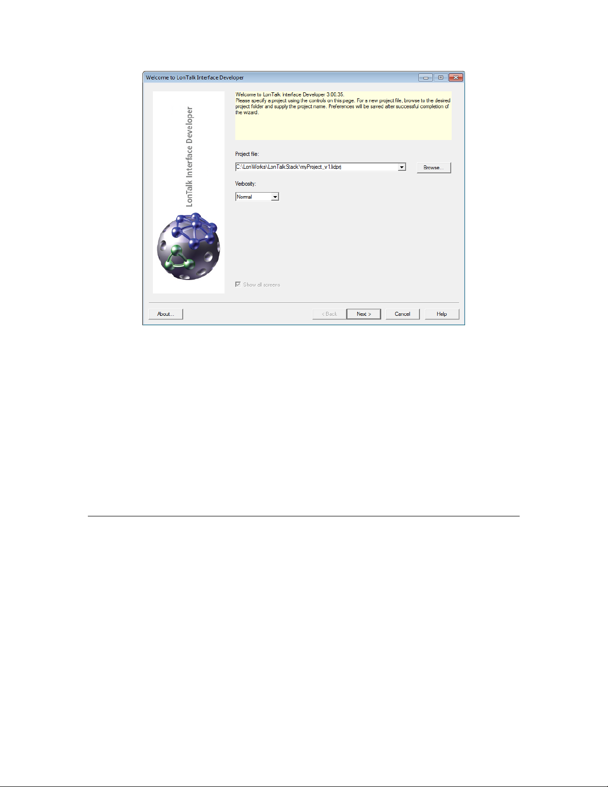
You can include a project version number in the name of the project to facilitate
version control and project management for your LonTalk Interface Developer
projects.
The utility creates all of its output files in the same directory as the project file.
Your application’s model file does not need to be in this directory; from the
utility’s Model File Selection page, you can specify the name and location of the
model file.
The location of the LonTalk Interface Developer project file can be the same as
your application’s project folder, but you can also generate and maintain the
LonTalk Interface Developer’s project in a separate folder, and manually link the
latest generated framework with your application by copying or referencing the
correct location.
Click Next and then click Yes to confirm the creation of the new project.
Specifying the Echelon Smart Transceiver or Neuron Chip Configuration
From the Echelon Smart Transceiver or Neuron Chip Configuration page of the
utility, you can specify the clock speed for the Echelon Smart Transceiver or
Neuron Chip.
LonTalk Stack Developer’s Guide 83
Page 96

Select a clock speed and then click Next.
In the System Preferences dialog, click Next (the LonTalk Stack does not have
access to the service pin; therefore, the options in this dialog do not affect your
LonTalk Stack device application).
Configuring the LonTalk Stack
From the Stack Configuration page of the utility, you can specify override values
for the following system definitions:
84 Using the LonTalk Interface Developer Utility
Page 97

• The size of the address table (the number of addresses)
• The size of the alias table (the number of aliases)
• The number of receive transaction records
• The number of transmit transaction records
• The maximum lifetime of a transmit transaction
If you do not specify an override value, the LonTalk Interface Developer utility
generates appropriate values based on other preferences that you specify for the
project.
You can select the options to automatically calculate values to have the LonTalk
Interface Developer utility calculate appropriate values for the stack
configuration.
Managing Memory for more information about these values.
See
Click Next.
Configuring the Buffers
From the Buffer Configuration page of the utility, you can specify the number for
each of the following application buffer types:
• Input buffers
• Non-priority output buffers
• Priority output buffers
You can also specify the number of link-layer buffers.
In addition, you can specify both the size and number for the transceiver buffers:
• Input buffers
LonTalk Stack Developer’s Guide 85
Page 98

• Non-priority output buffers
• Priority output buffers
You can select the options to automatically calculate values to have the LonTalk
Interface Developer utility calculate appropriate values for the buffer
configuration.
Click Next.
Configuring the Application
From the Application Configuration page of the utility, you can specify the
following parameters for the application:
• The number of dynamic network variables
• The average amount of memory to reserve for self-documentation data for
dynamic network variables
By default, the number of supported dynamic network variables is zero, but you
can specify up to 4096. During compilation, the utility verifies that the sum of
static and dynamic network variables does not exceed a total of 4096 for the
device.
86 Using the LonTalk Interface Developer Utility
Page 99

The average amount of memory to reserve for dynamic network variable
self-documentation strings is used, along with the number of dynamic network
variables, to calculate the maximum amount of non-volatile data that might be
required for the LonTalk Stack device. The actual size of a particular dynamic
variable’s self-documentation string can exceed the specified average, as long as
the actual average size is less than or equal to the specified average size.
The default size for the dynamic network variable self-documentation data is 16
bytes, but you can specify up to 128 bytes.
Click Next.
Configuring Support for Non-Volatile Data
From the Non-Volatile Data Support page of the utility, you can specify the
following parameters for the application:
• Non-volatile data driver model
• Non-volatile data flush guard timeout value
• Name for the top-level root segment for the non-volatile data
The non-volatile data driver model can be one of the following types, depending
on your application’s requirements:
• Flash file system (such as Linux)
• Flash direct memory (with no file system) if you do not have, or do not
want to use, a flash file system for your non-volatile data
• User defined if you have another non-volatile data support model that
your application uses
You can only select one driver model for the specified application.
LonTalk Stack Developer’s Guide 87
Page 100

The non-volatile data flush timeout value determines how long the LonTalk host
stack waits to receive additional updates before writing them to the non-volatile
data.
The non-volatile root name is used to configure the non-volatile data support
driver. If you use the flash file system, the non-volatile root name is used as a
file system directory name in which to create non-volatile data files. If you use
the direct flash model, the name represents a host processor flash device name.
If you use unstructured flash memory, leave the Root field blank.
Within the host processor development environment, the system.h file defines
the root name. For the examples that are included with the LonTalk Stack, the
root name is /dev/cfi_flash, which is the root directory for the flash file system.
The source files that handle non-volatile data (FtxlNvdFlashDirect.c,
FtxlNvdFlashFs.c, and FtxlNvdUserDefined.c) use conditional compilation
based on the selected model to include the appropriate code. If you select a
user-defined model, the related callback handler functions are not defined and
cause a linker error if they are not implemented.
Click Next.
Specifying the Device Program ID
From the Program ID Selection page of the utility, you specify the device
program ID or use the L
device program ID. The program ID is a 16-digit hexadecimal number that
uniquely identifies the device interface for your device.
The program ID can be formatted as a standard or non-standard program ID.
When formatted as a standard program ID, the 16 hexadecimal digits are
organized into six fields that identify the manufacturer, classification, usage,
channel type, and model number of the device. The L
ID Calculator simplifies the selection of the appropriate values for these fields by
88 Using the LonTalk Interface Developer Utility
ONMARK Standard Program ID Calculator to specify the
ONMARK Standard Program
 Loading...