

Page 1

LonPoint® Module
Hardware and Installation
User’s Guide
Version 2.0
C o r p o r a t i o n
078-0167-01B
Page 2

078-0167-01B
Echelon, LON, LONWORKS, LonBuilder, NodeBuilder, LonManager, LonTalk,
LONMARK, Neuron, 3120, 3150, LonPoint, the LonUsers logo, the LONMARK logo,
and the Echelon logo are trademarks of Echelon registered in the United States
and other countries. LonSupport and LonMaker are trademarks of Echelon
Corporation.
Other brand and product names are trademarks or registered trademarks of their
respective holders.
Neuron Chips, LonPoint Modules, and other OEM Products were not designed for
use in equipment or systems which involve danger to human health or safety or a
risk of property damage, and Echelon assumes no responsibility or liability for use
of the Neuron Chips or LonPoint Modules in such applications.
Parts manufactured by vendors other than Echelon and referenced in this
document have been described for illustrative purposes only and may not have
been tested by Echelon. It is the responsibility of the customer to determine the
suitability of these parts for each application.
ECHELON MAKES AND YOU RECEIVE NO WARRANTIES OR CONDITIONS, EXPRESS,
IMPLIED, STATUTORY OR IN ANY COMMUNICATION WITH YOU, AND ECHELON
SPECIFICALLY DISCLAIMS ANY IMPLIED WARRANTY OF MERCHANTABILITY OR
FITNESS FOR A PARTICULAR PURPOSE.
No part of this publication may be reproduced, stored in a retrieval system, or
transmitted, in any form or by any means, electronic, mechanical,
photocopying, recording, or otherwise, without the prior written permission of
Echelon Corporation.
Model Number 39510
Printed in the United States of America.
Copyright ©1997 - 1999 by Echelon Corporation.
Echelon Corporation
4015 Miranda Avenue
Palo Alto, CA 94304, USA
www.echelon.com
Page 3

Regulatory Information
FCC NOTICE (for USA only)
Federal Communications Commission Radio Frequency Interference Statement
Warning: This equipment has been tested and found to comply with the limits for a Class A
digital device, pursuant to Part 15 of the FCC Rules. These limits are designed to provide
reasonable protection against harmful interference when the equipment is operated in a
commercial environment. This equipment generates, uses, and can radiate radio frequency
energy and, if not installed and used in accordance with the instruction manual, may cause
harmful interference to radio communications. Operation of this equipment in a residential area
is likely to cause harmful interference in which case the user will be required to correct the
interference at his own expense.
This device complies with part 15 of the FCC Rules. Operation is subject to the following two
conditions: (1) This device may not cause harmful interference, and (2) this device must accept
any interference received, including interference that may cause undesired operation.
Safety
UL Listed, per UL-916.
c-UL (CSA) Certified, per C22.2, No. 205
Page 4

Page 5

Contents
1 Introduction 1-1
Applications 1-2
Audience 1-4
Content 1-4
Related Documents 1-4
2 Description of the LonPoint Modules and Base Plates 2-1
LonPoint Interface Modules 2-2
LonPoint Interface and Router Module Symbology 2-9
Network Connector 2-9
Front Panel Label 2-9
Service Switch/LED 2-9
Power or Power/Wink LED 2-10
I/O Number 2-10
Digital Input 2-10
Digital Output 2-10
Analog Input 2-10
Analog Output 2-11
Hand/Off/Auto Switch 2-11
Input Status LEDs 2-11
Output Status LEDs 2-11
Router Channel A 2-12
Router Channel B 2-12
Router Activity LED 2-12
3 Network Cabling and Connections 3-1
Network Cabling – TP/FT-10 Channel 3-2
System Performance and Cable Selection – TP/FT-10 Channel 3-4
TP/FT-10 Cable Termination 3-5
Free Topology 3-5
Doubly Terminated Bus Topology Segment 3-6
Terminating Shielded Cables for the TP/FT-10 Channel 3-6
Network Cabling – TP/XF-1250 Channel 3-7
Distribution Rule for TP/XF-1250 Channel 3-7
Terminator for TP/XF-1250 Channel 3-9
I/O Cabling 3-9
Power Cabling 3-9
4 Installation and Wiring of Base Plate 4-1
LonPoint Type 1 Base Plate Installation 4-2
Installing a Compatible Electrical Box 4-5
Connecting Wiring 4-8
LonPoint Type 1D DIN Base Plate Installation 4-9
Connecting Wiring 4-12
Connecting the Jumper Plug(s) 4-13
LonPoint Module Hardware and Installation Guide iii
Page 6

LonPoint Type 2 Base Plate Installation 4-17
Installing a Compatible Electrical Box 4-20
Connecting Wiring 4-23
LonPoint Type 2D DIN Base Plate Installation 4-24
Connecting Wiring 4-27
Connecting the Jumper Plug(s) 4-29
5 Installing the DI-10 Digital Input Module 5-1
LonPoint DI-10 Digital Input Module 5-2
DI-10 Module Software Settings 5-4
Installing the DI-10 Module 5-4
6 Installing the DIO-10 Digital Input/Output Module 6-1
LonPoint DIO-10 Digital Inpu/Outputt Module 6-2
DIO-10 Module Digital Inputs 6-3
DIO-10 Digital Input/Output Module Software Settings 6-5
DIO-10 Digital Input/Output Module Firmware 6-5
Installing the DIO-10 Digital Input/Output Module 6-5
7 Installing the DO-10 Digital Output Module 7-1
LonPoint DO-10 Digital Output Module 7-2
DO-10 Module Software Settings 7-5
Installing the DI-10 Module 7-5
8 Installing the AI-10 Analog Input Module 8-1
LonPoint AI-10 Analog Input Module 8-2
AI-10 Module Software Settings 8-6
Installing the AI-10 Module 8-6
9 Installing the AO-10 Analog Output Module 9-1
LonPoint AO-10 Analog Output Module 9-2
AO-10 Module Software Settings 9-5
Installing the AO-10 Module 9-4
10 Installing the SCH-10 Scheduler Module 10-1
LonPoint SCH-10 Scheduler Module 10-2
SCH-10 Module Software Settings 10-4
Installing the SCH-10 Module 10-4
11 Installing the LPR Router Module 11-1
LonPoint LPR Router Modules 11-2
Installing the LPR Router 11-5
12 Troubleshooting 12-1
Troubleshooting Table 12-2
Declaration of Conformity
iv Echelon
Page 7

1
Introduction
The LonPoint System is a family of products designed to integrate both
new and legacy sensors and actuators into cost-effective, interoperable,
control systems for building and industrial applications. Designed to
take best advantage of the LONWORKS® Network Services (LNS)
operating system, LONMARK® interoperability, and the distributed
processing capability of the Neuron® Chip and LonTalk® protocol, the
LonPoint System provides a truly distributed control architecture that
reduces installation time, lowers installation and life-cycle costs, and can
be economically integrated into applications both large and small.
LonPoint Hardware Guide 1-1
Page 8

Applications
Traditional control networks have been based on an hierarchical architecture using
proprietary controllers. This approach to control system design is expensive, complex,
and locks the customer into a closed, non-interoperable architecture. Ultimately, the
high costs of this design approach limits the market for control systems.
Overcoming the limits of traditional, closed, hierarchical systems is best accomplished
with a flat, fully distributed control architecture. Such a system must: (a) interface
with a broad range of sensors and actuators, (b) incorporate application programs that
blur the distinction between legacy sensors/actuators and intelligent, networked
devices, (c) include a design and installation tool that can seamlessly interconnect
everything in the control network, and (d) incorporate software that simplifies
hardware configuration and reduces commissioning time. Satisfying these diverse
requirements requires a systems approach to the architecture, hardware, and software;
it cannot be accomplished easily with a piecemeal collection of devices and components.
The LonPoint System is the result of just such a systems approach, providing at once
the low cost of a flat system architecture, the multi-user capabilities of the LNS
operating system, the distributed processing of capabilities of the Neuron Chip and
LonTalk protocol, and the wiring flexibility of free topology communications. The
system consists of the LNS-based LonMaker™ for Windows® Integration Tool, the
LonPoint Plug-In, LonPoint application programs, network interfaces, and LonPoint
interface, router, and scheduler modules.
The LonMaker for Windows tool is an LNS-based installation tool with a Visio™ user
interface and support for both LonPoint devices and 3rd party LONWORKS® devices. The
Visio user-interface provides a familiar, CAD-like design environment from which a control
system can be designed. Installation consists of interconnecting function blocks
(LONMARK objects) within LonPoint modules and 3rd party devices, using their
application resources to create a distributed control system. The LonMaker for Windows
tool can be used to design, configure, and commission a distributed control network, yet is
economical enough to be left behind as a maintenance tool. The LonPoint Plug-In is
provided with the tool to simplify the configuration of LonPoint devices.
Resident within each LonPoint module is a powerful, configurable LONMARK
application program. The program includes a variety of function blocks (i.e., PID
Controller, digital encoder, analog output, digital input, type translator) that are
configured by the LonMaker for Windows tool. Linking the function blocks of multiple
LonPoint modules, together with the resources of third pary LONWORKS® devices,
creates a distributed control system that is interconnected via the network, yet which
offers greater functionality, higher reliability, and lower cost than a traditional central
controller-based system. The LonPoint System may be operated as a self-contained
control system, integrated with other LONMARK or LONWORKS devices, or combined
with remote systems and a remote supervisory station via a WAN, IP, or PSTN
network to form a wide area control system.
The LonPoint interface, scheduler, and router modules provide I/O processing,
application resources, timekeeping, and routing for a LonPoint System. The interface
®
1-2 Introduction
Page 9

modules seamlessly integrate sensors, actuators, and controllers into peer-to-peer,
interoperable networks. There are several different interface modules, including the
DI-10 Digital Input Module (4 digital inputs with a status LED per input), DO-10
Digital Output Module (4 digital outputs with a separate hand/off/auto switch and
status LED per output), DIO-10 Digital Input/Output Module (2 digital inputs, 2 relay
outputs, status LEDs and hand/off/auto switches), AI-10 Analog Input Module (2
independent 16-bit analog inputs), and AO-10 Analog Output Module (2 independent
12-bit analog outputs with PID). The SCH-10 Scheduler Module provides scheduling or
data logging for the system.
LPR Router Modules can be used to create high speed backbones, optimize network
traffic, extend the size of the network, as well as to create bridges to other channels
containing third-party devices. LPR Routers are available in any combination of TP/FT10, TP/XF-78, and TP/XF-1250 channels.
Many innovative labor-saving features have been built into the LonPoint modules to
minimize installation time:
• A two-piece design allows pre-wiring and cable testing by an electrician prior to
installing the electronics. Technician time can be reserved for tasks such as node
configuration;
• Screw terminals and polarity-insensitive power and network connections
minimize the chance of miswiring;
• All modules operate from 16-30VAC or VDC, allowing the modules to be powered
from the same sources as the sensors and actuators;
• Power and network wiring are “looped” through each base plate, providing
continuity in case of module replacement without network disruption;
• All modules can be hot-plugged, minimizing service time;
• Every module includes a front panel jack that accesses the twisted pair network
without any disassembly, saving time when the network must be accessed for
configuration or maintenance;
• All modules include a front panel bar code with the model, software revision,
and two removable Neuron Chip ID stickers. When placed on the building or
system design plans, these stickers save installation time, especially for
inaccessible nodes.
When used in the context of a complete LonPoint System, the LonPoint modules
provide tremendous flexibility and lower overall equipment, installation, and life-cycle
costs. The modules simplify programming by using a CAD-like design environment,
minimize cabling requirements by using free topology transceivers, and reduce the
need for on-site calls by offering over-the-network downloading. The LonPoint
modules support a flat architecture that is at once interoperable, lower cost to install
and maintain, and flexible enough for future adds, moves, and changes.
LonPoint Hardware Guide 1-3
Page 10

Audience
This User’s Guide is intended for anyone designing or installing a control network
using LonPoint Modules. Electricians and installation technicians involved with the
physical installation of the cable plant and hardware will find this User’s Guide
sufficient for them to complete their work. Designers and those charged with
commissioning LonPoint Modules, including those who will configure the LonPoint
software, must also review the the user’s guide for the LonMaker for Windows
Integration Tool as well as the LonPoint Application and Plug-In Guide.
Content
This manual provides detailed technical specifications on the electrical and mechanical
interfaces and operating environment characteristics for the LonPoint Modules.
Related Documentation
The following Echelon documents are suggested reading:
SLTA-10 Adapter User’s Guide (078-0160-01)
LONWORKS PCLTA-10 PC LonTalk Adapter User’s Guide (078-0159-01)
LONWORKS PCC-10 PC Card User’s Guide (078-0155-01)
LonManager Protocol Analyzer User’s Guide (078-0121-01)
LonPoint Application and Plug-In Guide (078-0166-01)
LonMaker for Windows User’s Guide (078-0168-01)
Junction Box and Wiring Guidelines for Twisted Pair LONWORKS Networks
(engineering bulletin 005-0023-02)
1-4 Introduction
Page 11

2
Description of the LonPoint
Modules and Base Plates
This chapter provides a description of the LonPoint Interface, Router, and
Scheduler modules, Type 1 and Type 2 Base Plates, and Type 1D and
Type 2D DIN Base Plates mounting enclosures.
LonPoint Hardware Guide 2-1
Page 12

LonPoint Interface Modules
The LonPoint Interface Modules are designed to monitor and control a wide variety of
analog and digital sensors and actuators, and are the primary means of interfacing a
LonPoint system to devices that lack an integral LONWORKS interface, i.e., a Neuron
Chip and transceiver. By selecting the correct LonPoint Interface Module and
configuring both its hardware and software correctly, a wide and varied assortment of
sensors and actuators can be supported.
There are five types of LonPoint Interface Modules which share a common form factor
but differ in terms of their I/O and internal software functions. The five modules
include the DI-10 Digital Input Module, DO-10 Digital Output Module, DIO-10 Digital
Input Output Module, AI-10 Analog Input Module, and AO-10 Analog Output Module.
The DI-10 Digital Input Module provides four digital inputs for supervising voltage
ranges 0-5VDC through 0-32VDC or dry contacts. Inputs are isolated from the input
power and the network but not from each other. Separate status LEDs are provided for
each input.
The DO-10 Digital Output Module includes four digital outputs rated at 0-12V, 100mA
source/sink per output, 110mA source, 400mA sink all outputs combined. Outputs are
isolated from the input power and the network but not from each other. Each output
may be separately overridden by a hand/off/auto switch accessible from the front panel.
Separate status LEDs are provided for each output.
The DIO-10 Digital Input Output Module provides two digital inputs and two relay
outputs. The digital inputs include configurable input thresholds for supervising dry
contacts or 5V, 12V, 24V, or 31V DC inputs. In addition, the digital inputs can be set to
measure frequency (20kHz) inputs. The inputs are isolated from the input power and
the network, but are not isolated from each other. Each relay output consists of a Form
A (normally open) and Form B (normally closed) contact which share a common wiper.
The relay contacts are rated for 2A continuous, 6A momentary, at 30VAC or 42VDC.
Each output may be separately controlled by a hand/off/auto switch accessible from the
front panel. Separate status LEDs are provided for each input and output.
The AI-10 Analog Input Module provides two independent 16-bit resolution analog
inputs which are isolated from the input power and the network but not from each
other. Each input can be configured via jumper blocks to monitor RTDs, thermistors,
and other types of analog inputs. Inputs can be separately configured as a voltage input,
resistive transducer input, loop-powered 0-24mA current input, or remote-powered 024mA current input. Voltage input ranges can be selected via the LonPoint Plug-in to
be 0-156mV, 0-625mV, 0-10V, or 0-20V. Current input ranges can be set via the
LonPoint Plug-in to be 0-25mA, 0-12.5mA, 0-781µA, or 0-19.5µA. Resolution in the 020V range is 0.3mV per step; current input resolution in the 0 - 25mA range is 0.37µA
per step. For resistive transducers, the module includes a configurable current source
which can be set, under software control, to provide either 25µA or 400µA current for
resistance measurement of transducers from 100 to 15k (nominal).
The AO-10 Analog Output Module offers two independent 12-bit resolution analog
outputs. Each output can be separately configured for voltage or current output, and
can drive 0-10V into a 1k load or 0-20mA or 4-20mA @ 0-12V. Outputs are isolated
from the input power and the network but not from each other.
2-2 LonPoint Modules and Base Plates
Page 13
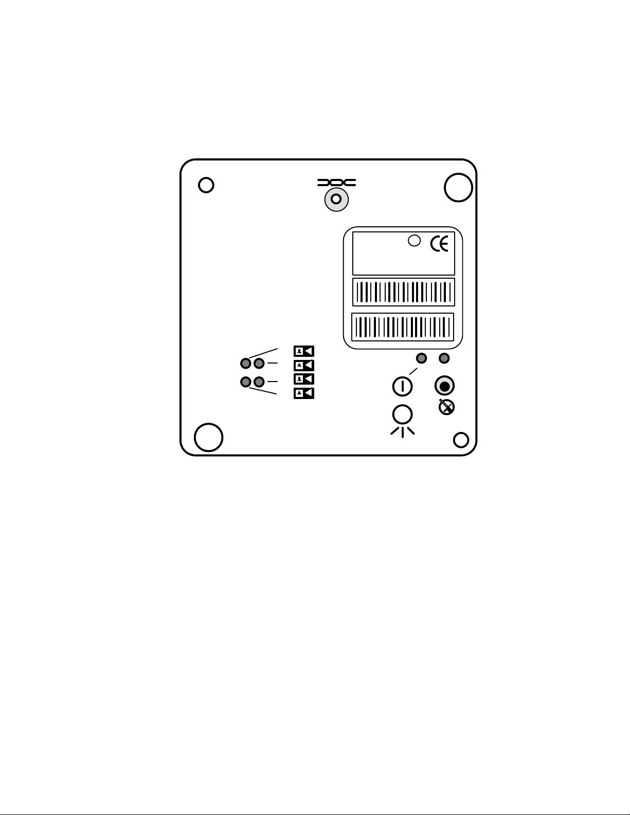
The LonPoint Interface Modules share a common form factor that includes a front panel
LonPoint™ Interface
assembly to which a printed circuit board (PCB) with active electronics is connected.
The front panel of all of the modules includes a service switch and service LED, a
combination power/wink LED, and a network connector (figure 2.1).}
E
DI-10
MODEL 41100 972
SW VERSION 1.0
ID NUMBER
INPUT: 0-32VDC
DI-10 MODEL 41100 ID NUMBER
DI-10 MODEL 41100 ID NUMBER
U
®
L
c us
m
LISTED 178K
ENERGY MANAGEMENT
EQUIPMENT SUBASSEMBLY
1
2
3
4
Figure 2.1 LonPoint Interface Module - Typical Front Panel
The rear of the PCB assembly includes a polarized, shrouded, 14-pin interface connector
that connects to a mating socket in a Type 1 Base Plate or Type 1D DIN Base Plate. Any
user-configured jumpers are also located on the rear of the PCB assembly (figure 2.2).
LonPoint Hardware Guide 2-3
Page 14
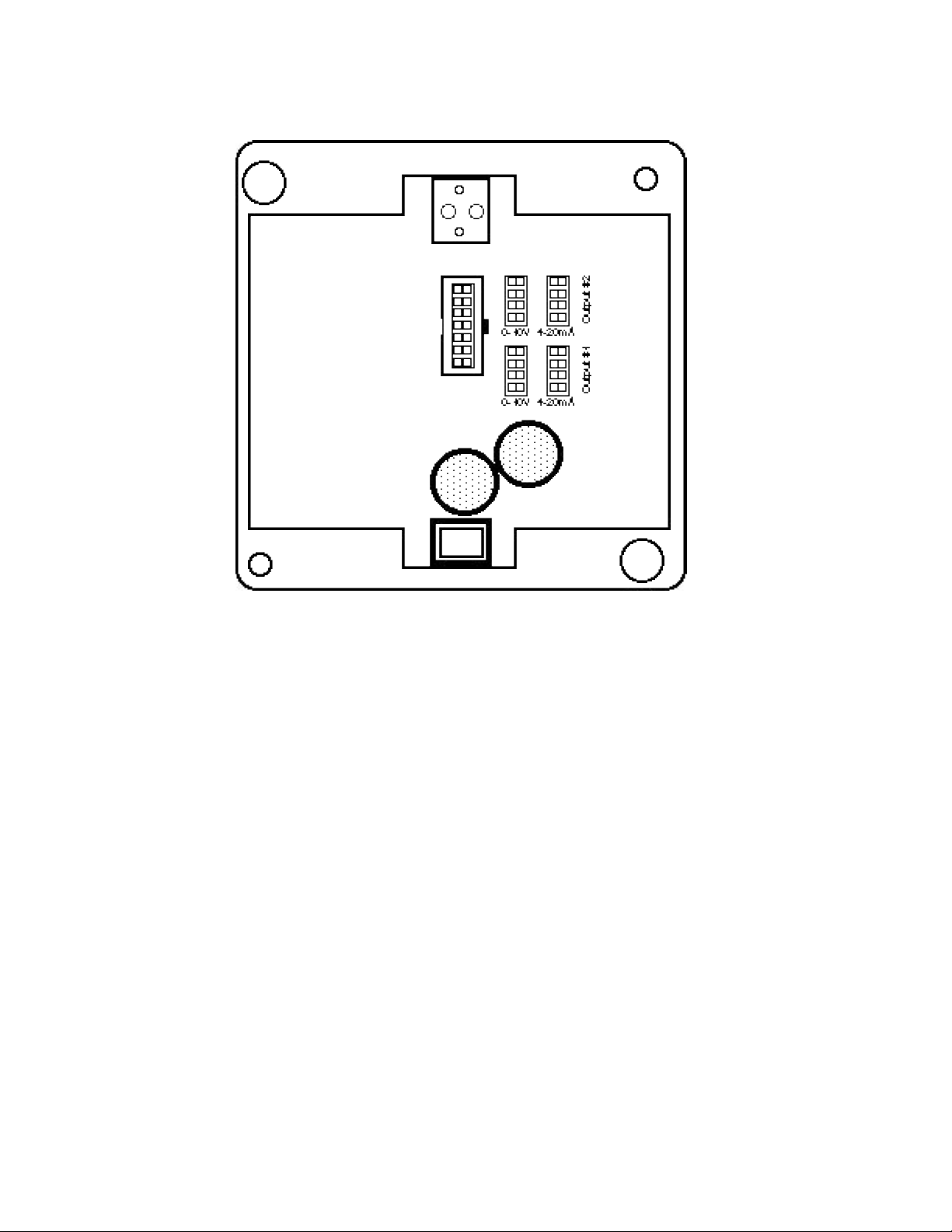
Figure 2.2 LonPoint Interface Module - Typical Rear Panel and Jumpers
Network, power, and I/O wiring is connected to screw terminals located on a Type 1
Base Plate (figure 2.3) or Type 1D DIN Base Plate (figure 2.4), into which the LonPoint
Interface Module is plugged; no wiring is ever connected directly to an Interface Module.
A writing space is provided on the back of the Type 1 Base Plate for recording the date
of installation or other pertinent information. Installers should take care to use a finepoint (smudge-free) pen.
Type 1/1D and Type 2/2D Base Plates are keyed to prevent accidental insertion of an
incorrect module type. The Type 1 Base Plate (Model 40111) and the Type 1D DIN Base
Plate (Model 48111) will only accommodate Interface Modules and Scheduler Modules.
The Type 2 Base Plate (Model 40222) and the Type 2D DIN Base Plate (Model 48222)
will only accept LPR-1X Router Modules.
In either Type 1/1D or Type 2/2D Base Plates, the associated module is affixed to the
Base Plate by means of two 8-32, 3/8” screws (Echelon 205-0130-01) that are provided
with each module.
2-4 LonPoint Modules and Base Plates
Page 15
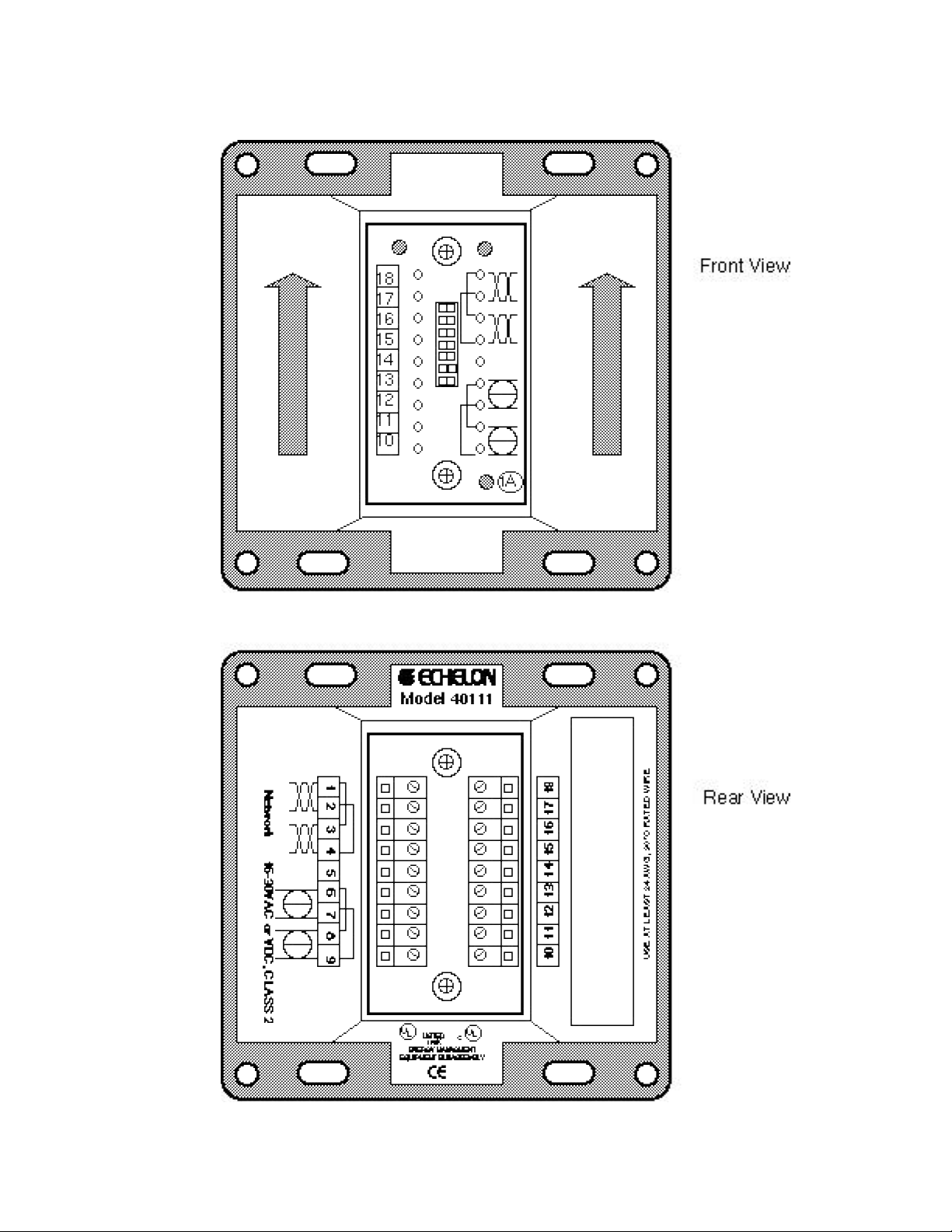
Figure 2.3 LonPoint Type 1 Base Plate
LonPoint Hardware Guide 2-5
Page 16

18 17 16 15 14 13 12 11 10
CAUTION
18
17
16 15 14
I/O
1A
13
12 11 10
Front View
Network
1 2
3 4 5 6 7 8 9
1 2 3 4 5 6 7 8 9
Jumper Plug
(one supplied with
each DIN Base
Plate)
Figure 2.4 LonPoint Type 1D Base Plate
2-6 LonPoint Modules and Base Plates
Page 17

The Type 1 Base Plate is mounted to either a suitable US 4” square, 2” deep (10.16cm x
5.08cm) electrical box, US double gang electrical box, plastic Echelon EuroBox (figures
2.5-2.7), or an IP-65 (NEMA 4) enclosure.
Figure 2.5 LonPoint Interface Module 4” Square (2” Deep) Electrical Box Mounting Configuration
Figure 2.6 LonPoint Interface Module Double Gang (2” Deep) Electrical Box Mounting Configuration
Figure 2.7 LonPoint Interface Module Eurobox Mounting Configuration
LonPoint Hardware Guide 2-7
Page 18

The Type 1D DIN Base Plate may be mounted to either a 35mm DIN rail or to a wall
panel (figures 2.8). A jumper plug supplied with the Base Plate permits the power and
network connections of several Type 1D DIN Base Plates to be interconnected without
additional wiring.
Figure 2.8 LonPoint Interface Type 1D Base Plate Mounting Configuration
Prior to installing the base plate, it is important to understand the symbology used on
the base plates, interface modules, and router modules.
2-8 LonPoint Modules and Base Plates
Page 19

LonPoint Interface and Router Module Symbology
DI-10 MODEL 41100 ID NUMBER
The front and rear panels of the LonPoint Modules and Base Plates contain legends that
identify the function of the module and its various LEDs, switches, and network
connector. A common legend marking scheme is used that allows the module to be
rotated clockwise 90° and still be legible, in the event that the mounting enclosure is
installed off axis. The symbols used are as follows:
Network Connector
Each module includes a network connector for accessing the TP/FT-10 network directly
from the front panel. This feature is intended to allow a laptop PC equipped with a
Model 73200 PCC-10 PC Card and Model 78303 cable assembly to plug into the
LonPoint module and program, monitor, troubleshoot, or update a LonPoint system.
The 3.5mm mating plug is a Hosiden 315-0201-01 miniature phone jack, or equal.
Front Panel Label
U
®
c us
DI-10
MODEL 41100 972
SW VERSION 3.0
ID NUMBER
INPUT: 0-32VDC
L
m
LISTED 178K
ENERGY MANAGEMENT
EQUIPMENT SUBASSEMBLY
DI-10 MODEL 41100 ID NUMBER
Every module is supplied with a front panel label that identifies the model number and
software version number of the module. The front panel label also includes two peel-off
Code 39 bar code labels on which are printed the Neuron Chip ID of that module (LPR
modules have two Neuron Chip IDs, one per channel). These labels are intended to
assist the installer during installation time, and may be removed from the module and
placed on installation drawings for reference purposes.
Service Switch/LED
Every module includes a service switch and LED which may be used during module
installation and to identify configured and unconfigured modules.
LonPoint Hardware Guide 2-9
Page 20

Power or Power/Wink LED
Every module includes either a power LED or a combination power/wink LED. The
wink function is used by a network management/installation tool to visually identify a
particular module; the wink command causes the power LED to blink.
I/O Number
1
2
3
4
Every input and output symbol is accompanied by an I/O Number designating which
hardware input or output the function is associated. The DI-10 has four inputs, the DO10 has four outputs, the DIO-10 has two inputs and two outputs, the AI-10 has two
inputs, and the AO-10 has two outputs.
Digital Input
This symbol designates the I/O as a digital input and is accompanied by an I/O Number.
Digital Output
This symbol designates the I/O as a digital or relay output and is accompanied by an I/O
Number.
Analog Input
This symbol designates the I/O as an analog input and is accompanied by an I/O
Number.
2-10 LonPoint Modules and Base Plates
Page 21

Analog Output
0
4
4
This symbol designates the I/O as an analog output and is accompanied by an I/O
Number.
Hand/Off/Auto Switch
1 2 3 4
1 2 3 4
1
1 2
DO-10 Hand/Off/Auto Switch DIO-10 Hand/Off/Auto Switch
The DO-10 and DIO-10 modules include a Hand/Off/Auto switch that allows the user to
determine the mode of operation of the outputs. One three-position switch is provided
for each of the four outputs. The switch positions function as follows:
1 2 3 4
1 Output turned ON (voltage level high or relay actuated)
0 Output turned OFF (voltage level low or relay not actuated)
Output state is determined automatically according configuration programs
loaded into the LonPoint modules on the network.
Input Status LEDs
1
2
3
Input status LEDs indicate the state of the inputs.
Output Status LEDs
1
2
3
Output status LEDs indicate the logical state of the outputs.
LonPoint Hardware Guide 2-11
Page 22

Router Channel A
A
LPR Routers route packets between two twisted pair channels, designated A and B.
Router Channel B
B
LPR Routers route packets between two twisted pair channels, designated A and B.
Router Activity LED
Indicates that a router is transferring packets from one channel to another.
2-12 LonPoint Modules and Base Plates
Page 23

3
Network Cabling and Connections
This chapter provides information about network, power, and
input/output cabling for the LonPoint system.
LonPoint Hardware Guide 3-1
Page 24

Network Cabling - TP/FT-10 Channel
The LonPoint modules (excluding some LPR Routers) use Echelon’s FTT-10A Free
Topology Transceiver for network communications. This transceiver operates at 78
kilobits per second and is designed to support free topology wiring; it will accommodate
bus, star, loop, or any combination of these cabling topologies using a twisted pair cable.
By eliminating restrictions on the cabling topology, the installer is free to locate
LonPoint modules anywhere on the network cabling provided only that the maximum
cabling distance limitations are observed99 This capability simplifies system installation
and makes it easy to add nodes should the network need to be expanded. Figures 3.1
through 3.5 present five typical network topologies.
In free topology cabling it is necessary to use one Echelon Model 44100 terminator.
In bus topology cabling it is necessary to use two Echelon Model 44101 terminators.
Terminators are required for proper network operation and must not be omitted.
Termination
Figure 3.1 Singly Terminated Bus Topology (Model 44100 Terminator)
Termination
Figure 3.2 Star Topology (Model 44100 Terminator)
Termination
Figure 3.3 Loop Topology (Model 44100 Terminator)
3-2 Network Cabling and Connections
Page 25

Termination
Figure 3.4 Mixed Topology (Model 44100 Terminator)
TerminationTermination
Figure 3.5 Doubly Terminated Bus Topology - Used for Very Long Cabling Distances
(Two Model 44101 Terminators)
A network consisting of LonPoint modules using the FTT-10A transceiver is said to
reside on a “TP/FT-10 channel.” In some cases all of the LonPoint modules will be
connected to a single TP/FT-10 channel. A maximum of 64 devices (LonPoint
modules, routers, PCLTA-10 and PCC-10 PC adapters, third-party LONMARK
®
devices) may be connected to any one channel. If more than 64 devices are to be
used, or if it is necessary to add more cabling than is permitted on a single channel,
then one or more model 42100 LPR-10 Routers (TP/FT-10 to TP/FT-10) would be
placed in series with the network cabling.
Another application for the LPR Router is to limit the amount of network
communications passing between different parts of a control network. For example,
LPR Routers can restrict the transfer of messages from a portion of the network
with many active PID loops to other, more quiescent parts of the network. In this
case one or more model 42100 LPR-10 Routers would be placed in series with the
network cabling.
The LPR Router can also be used to create a high-speed backbone that brings
together many different channels, perhaps to a monitoring PC. In this case it may
be desirable to increase the speed of the backbone channel in order to better manage
the communication traffic. For example, in a highrise building it might be desirable
to have a78 kilobit per second TP/FT-10 free topology channel operating on each
floor, and use a 1.25 megabit per second channel to link together all of the floor
channels with a PC in the basement. In this case, one model 42102 LPR-12 Router
(TP/FT-10 to TP/XF-1250) would be placed on each floor and a separate 1.25Mbps
twisted pair channel would serve as a backbone.
LonPoint Hardware Guide 3-3
Page 26

The Model 42100 LPR-10 Router (TP/FT-10 to TP/FT-10) uses the TP/FT-10 channel
cabling scheme. The Model 42102 LPR-12 Router (TP/FT-10 to TP/XF-1250) uses a
different cabling scheme that is designed to handle high speed, 1.25Mbps
communications. This 1.25Mbps cabling scheme is described in a later section.
System Performance and Cable Selection - TP/FT-10 Channel
The system designer may choose a variety of cables, depending on cost, availability,
and performance. Currently, Echelon has documented system performance on the
cable types shown in tables 3.1 and 3.2. Up to 64 devices may be connected to each
channel; one or more Model 42100 LPR-10 Routers may be used to increase the
number of devices and cable distance. Network performance specifications assume
that the average wire temperature is +55°C, although individual segments of wire
may be as hot as +85°C.
The free topology transmission specification includes two components which must
both be met for proper system operation. The distance from each LonPoint module,
network interface, or third party device to all other devices, and the distance from
each LonPoint module, network interface, or third-party device to the Model 44100
Terminator, must not exceed the maximum node-to-node distance. If multiple paths
exist, e.g., a loop topology, then the longest path should be used for the calculations.
The maximum total wire length is the total amount of wire connected per channel.
Table 3.1 Free Topology Specifications
Maximum
node-to-node
distance
Belden 85102 500 meters 500 meters 16AWG/1.3mm
Belden 8471 400 meters 500 meters 16AWG/1.3mm
Level IV, 22AWG 400 meters 500 meters 22AWG/0.65mm
JY (St) Y 2x2x0.8 320 meters 500 meters 20.4AWG/0.8mm
TIA Category 5 250 meters 450 meters 24AWG/0.51mm
Maximum total
wire length
Wire Diameter
AWG/mm
3-4 Network Cabling and Connections
Page 27

If a shielded cable is used, the shield should be connected to earth ground via the
termination circuit shown in the LONWORKS FTT-10A Free Topology Transceiver
User's Guide, version 5 or later.
Distributors of cable are listed in Echelon’s engineering bulletin, Junction Box and
Wiring Guidelines, part number 005-0023-01.
Table 3.2 Doubly-Terminated Bus Topology Specifications
(Requires Two Model 44101 Terminators)
Wire Diameter
Maximum bus length
AWG/mm
Belden 85102 2700 meters 16AWG/1.3mm
Belden 8471 2700 meters 16AWG/1.3mm
Level IV, 22AWG 1400 meters 22AWG/0.65mm
JY (St) Y 2x2x0.8 900 meters 20.4AWG/0.8mm
TIA Category 5 900 meters 24AWG/0.51mm
A doubly-terminated bus may have cable lengths (stubs) of up to 3 meters from the
bus to each LonPoint module, network interface, or third-party device.
TP/FT-10 Cable Termination
The TP/FT-10 channel must be terminated for proper data transmission performance.
Free Topology
If free topology cabling is used then only one Model 44100 Terminator is required and
may be placed anywhere on the free topology segment, as shown in figure 3.6. The
Model 44100 Terminator's orange wires should be connected to the twisted pair
network. The Terminator's green wire must be connected to earth ground. The green
wire must never be connected to the shield of a twisted pair cable.
orange
44100
Terminator
Figure 3.6 Single Termination for Free Topology (Model 44100 Terminator)
green
Network
Termination
LonPoint Hardware Guide 3-5
Page 28

Doubly Terminated Bus Topology Segment
+
+
If a doubly-terminated bus topology is used, then two Model 44101 terminators are
required, one at each end of the bus, as shown in figure 3.7. The Model 44100
Terminator's orange wires should be connected to the twisted pair network. The
Terminator's green wire must be connected to earth ground. The green wire must
never be connected to the shield of a twisted pair cable.
orange
green
44100
Terminator
orange
green
Network
TerminationTermination
Network
Figure 3.7 Double Termination for Bus Topology (Two Model 44101 Terminators)
Terminating Shielded Cables for the TP/FT-10 Channel
Model 44100 and 44101 Terminators are intended for use exclusively with unshielded
twisted pair cables and must NOT be used as terminators for shielded cables. If a
shielded cable is to be used then special Terminators must be fabricated for both free
topology and bus cabling architectures. These special Terminators will ensure the
effectiveness of the shield in providing noise immunity in electromagnetically harsh
environments. Figure 3.8 presents the schematic for a Free Topology Shielded Cable
termination.
C1 R2 R4
Network
Cable
Terminator
Ground
44101
R1
Network
Cable
Cable
Shield
C2 R3
78.7
1%, 1/8W
R1, R2, R3
R4
C1, C2
ž,
150ž, 1%, 1/8W
100µF±10%, 50V minimum aluminumelectrolytic type (observe polarity)
Figure 3.8 Free Topology Network Terminator for use with Shielded Cables
(Use only one Terminator.)
Figure 3.9 presents the schematic for a Bus Topology Shielded Cable termination.
3-6 Network Cabling and Connections
Page 29

C1 R2 R4
+
+
Network
Cable
R1
Network
Cable
C2 R3
ž,
316
R1,
R2, R3
R4
C1, C2
1%, 1/8W
ž,
78.7
1%, 1/8W
150ž, 1%, 1/8W
100µF±10%, 50V minimum aluminumelectrolytic type (observe polarity)
Figure 3.9 Bus Topology Network Terminators for use with Shielded Cables (Two Required)
Network Cabling - TP/XF-1250 Channel
If a high-speed backbone is created using the Model 42102 LPR-12 Routers (TP/FT-10
to TP/XF-1250), then a doubly-terminated bus topology using data grade cable that is
intended specifically for this channel must be installed. The TP/XF-1250 channel can
be used only with Level IV, 22 AWG (0.65mm) twisted pair cable, and the channel
must be terminated at each end with a Model 44200 Terminator (do NOT use the
Model 44100 or 44101 Terminators.) Suppliers of cable are listed in Echelon’s
engineering bulletin, Junction Box and Wiring Guidelines, part number 005-0023-01,
Rev D or higher.
Ground
Cable
Shield
Under no circumstances should smaller gauge Level IV cable be substituted for Level
IV, 22 AWG (0.65mm) twisted pair cable. Echelon periodically qualifies new cables for
twisted pair transceivers, and it is advisable to check with Echelon from time to time
to determine if new cables are available. DO NOT attempt to use any other type of
cabling, including but not limited to Category 5 data cabling, or improper or erratic
operation will result.
A maximum of sixty-four (64) Model 42102 LPR-12 Routers (TP/FT-10 to TP/XF-1250), PC
adapters, and other devices can be installed on a backbone channel, with a maximum
cable length of 130 meters with a maximum stub length of 1 feet (0.3m). If additional
cabling or devices must be installed, then one or more model 42105 LPR-15 (TP/XF-1250
to TP/XF-1250) Routers may be placed in series with the backbone cabling.
Distribution Rule for TP/XF-1250 Channel
Due to the transmission characteristics of the TP/XF-1250 channel, communication
failures may result from reflections of the TPT/XF-1250 transceiver’s 1.25Mbps
LonPoint Hardware Guide 3-7
transmitted signal under conditions where devices are concentrated in one point of
cabling. These communication failures are eliminated when devices are used in a
Page 30

distributed configuration. For this reason, it is essential to follow a simple topology
rule when using the TPT/XF-1250 channel.
Referred to as the “8-in-16” topology rule, this rule requires that no more than 8
devices be connected to the TP/XF-1250 channel within any 16 meter length of cable.
This means that no matter where along the bus the 16 meter measurement is taken,
there should be no more than 8 devices. Figure 3.10 provides a diagram of such a
measurement technique.
Figure 3.10 8-in-16 Topology Rule Example
In the example we see an installation with six groups of devices, varying in size from 2
to 7 devices, in a doubly-terminated bus that is terminated with Model 44200
Terminators. By using a 16 meter measurement stick that we can move from side-toside over the length of the bus, we can determine whether the 8-in-16 rule has been
met (designated by the word "OK") or violated (shown by the designation "PROBLEM").
In the case of the PROBLEM area, a total of 13 devices are located within a 16 meter
length of the bus, which amounts to five more devcies than are permitted under the 8in-16 rule.
There are two solutions that can be applied to situations in which the 8-in-16 rule has
been, or must be, violated by virtue of the installation scenario. The first and simplest
remedy is to insert a Model 42105 LPR-15 Router (TP/XF-1250 to TP/XF-1250) and two
Model 44200 Terminators in the bus to break the network into two channels (figure 3.11).
Since each side of the router comprises a different channel, the bus is effectively split and
the nodes divided between two channels.
Figure 3.11 Using a Router to Meet the 8-in-16 Topology Rule
The second remedy to a violation of the 8-in-16 rule is to add additional cable to the
bus such that the rule is no longer violated (figure 3.12). It is important to ensure
that the maximum bus length (130 meters of 22AWG/0.65mm Level IV twisted pair)
is not exceeded by the additional cable. Due to the complex interactions between the
bus and the devcies with regard to reflections and transmission line delays, it is not
possible to substitute an inductor/capacitor network in lieu of the additional cable to
resolve this rule violation.
3-8 Network Cabling and Connections
Page 31

Figure 3.12 Using Additional Bus Cable to Meet the 8-in-16 Topology Rule
Terminator for TP/XF-1250 Channel
It is necessary to terminate both endpoints of the TP/XF-1250 channel twisted pair
bus for proper data transmission performance. Failure to terminate the bus will
degrade network performance. Use only the Model 44200 Terminator, and connect
it as shown in figure 3.13.
orange
44200
Terminator
Network
green
Figure 3.13 Double Termination for Bus Topology (Two Model 44200 Terminators)
I/O Cabling
The installer generally has wide latitude in the type of cabling selected for the I/O.
It is good practice to ensure that all I/O cabling is made from twisted pair wire, as
this has the advantage of minimizing susceptibility to differential noise. If the sensor
or actuator requires a shield then a ground will have to be provided in the electrical
box since the LonPoint modules are floating and do not include a ground screw
connection. Note when selecting the I/O cabling that the Base Plate screw terminals
accommodate wire guages from 24AWG/0.5mm to 12AWG/2mm. In all cases, use at
least 90°C rated wire.
Power Cabling
orange
TerminationTermination
Network
green
44200
Terminator
It is important to note that a maximum of 16 Amperes RMS at 24VAC RMS can be
passed through the internal jumpers on the Power terminals of the Type 1/2 Base
Plates, 10 Amperes RMS at 24 VAC RMS for Type 1D/2D DIN Base Plates using
Jumper Plugs. This means that if power wiring is looped in and out of the power
terminals of the LonPoint Base Plates, the current load presented by all of the
LonPoint modules and any other devices powered by that circuit must be 16
Amperes ( 10 Amperes for Type 1D/2D DIN Base Plates using Jumper Plugs), as
LonPoint Hardware Guide 3-9
Page 32
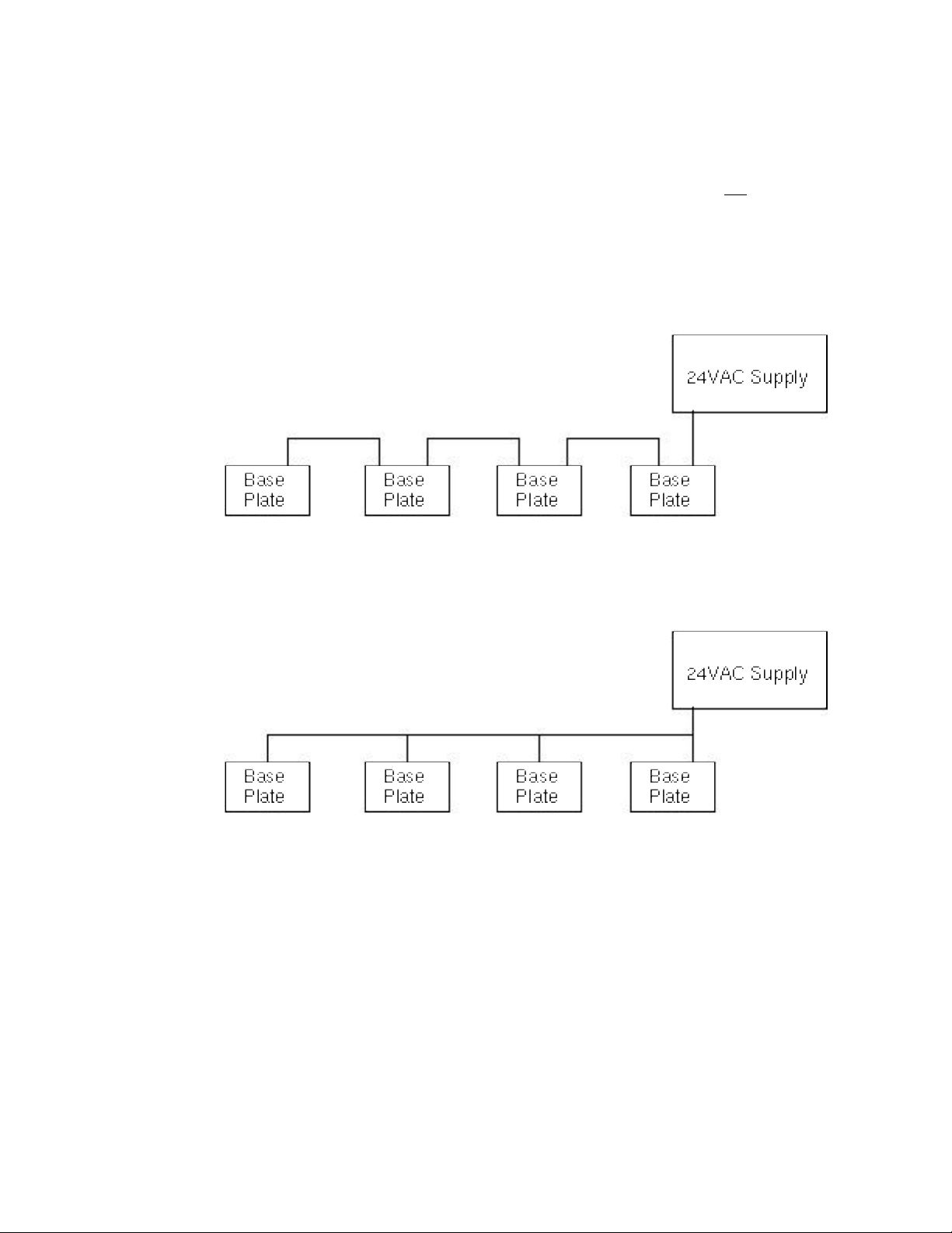
shown in figure 3.14. If >16 Amperes (>10 Amperes RMS at 24 VAC RMS for Type
1D/2D DIN Base Plates using Jumper Plugs) must be supplied then the loopthrough capability of the LonPoint Base Plate power terminals must not be used and
the power cabling should be run in parallel, as shown in figure 3.15. To calculate
the load current, divide the total VA (sum of all devices powered by the power
supply) by the power supply voltage. For example, if the total VA of all LonPoint
Modules and sensors/actuators equals 100VA, and the power supply provides 24
VAC, then the load current is 4.16A.
Figure 3.14 Looped-through Power Wiring - •16 Amperes at 24VAC for Type 1/2 Base
Plates, •10 Amperes for Type 1D/2D DIN Base Plates using Jumper Plugs
Figure 3.15 Parallel Power Wiring - >16 Amperes at 24VAC for Type 1/2 Base Plates,
•10 Amperes for Type 1D/2D DIN Base Plates using Jumper Plugs
As a rule of thumb, it is recommended that power and I/O cabling be separated by
18”/ 46cm to prevent inadvertent pick-up of noise from the power circuit by sensitive
analog I/O cabling. Power and network twisted pairs may be combined in a common
cable if using an approved network cable.
Depending on the model, the LonPoint modules require between 2 and 6.5VA at an
operating voltage of 16 to 30V DC or AC. The LonPoint Type 1/1D and Type 2/2D
Base Plates include a power-looping capability that provides continuity through the
Base Plate - even if the LonPoint module is removed - when the power cabling is
daisy-chained through each Base Plate.
3-10 Network Cabling and Connections
Page 33
Tables 3.4 and 3.5 present the wire gauge that should be used in order to deliver the
Meters
AWG
specified power (total VA) across the distance shown. These tables only include wire
gauges from 24AWG (0.5mm) to 12AWG (2mm) as these are the wire gauges
supported by the Base Plate screw terminals. For the supply cabling use at least
24AWG/0.5mm, 90° C rated wire.
To determine the total power that a power cable must carry, total the VA
requirements for all of the devices that will be drawing power from that cable,
including both LonPoint modules and other devices. The VA ratings for the
LonPoint Modules are shown in the module data sheets and are summarized in the
following table.
Table 3.3 VA Ratings for LonPoint Modules
LonPoint Module VA Rating
DI-10 2.2VA
DO-10 6.5VA
DIO-10 4.75VA
AI-10 (all modes except 2-wire mode) 2.1VA
AI-10 (2-wire mode) 4.5VA
AO-10 4.5VA
SCH-10 2.4VA
LPR 2.0VA
To determine what gauge cable (in AWG or metric) will be required based on the total distance of
the power cabling, refer to table 3.4 for cabling measured in AWG and table 3.4 for cabling
measured in mm. If the wire gauge used is smaller than required, improper operation of one of
more modules will result. All data in tables 3.4 and 3.5 assume an average wire temperature of
+55°C.
Table 3.4 Power Cabling Requirements in AWG
Load (VA)
Feet
10 15 20 25 30 40 55 75 100 130 180 200
35 10.7 22 22 22 22 22 22 22 22 22 22 22 22
40 12.2 22 22 22 22 22 22 22 22 22 22 22 20
55 16.8 22 22 22 22 22 22 22 22 22 22 20 20
65 19.8 22 22 22 22 22 22 22 22 22 20 20 18
70 21.3 22 22 22 22 22 22 22 22 22 20 18 18
75 22.9 22 22 22 22 22 22 22 22 22 20 18 18
90 27.4 22 22 22 22 22 22 22 22 20 20 18 18
100 30.5 22 22 22 22 22 22 22 22 20 18 18 16
105 32.0 22 22 22 22 22 22 22 20 20 18 18 16
115 35.1 22 22 22 22 22 22 22 20 20 18 16 16
135 41.1 22 22 22 22 22 22 22 20 18 18 16 16
145 44.2 22 22 22 22 22 22 20 20 18 18 16 16
150 45.7 22 22 22 22 22 22 20 20 18 16 16 16
LonPoint Hardware Guide 3-11
Page 34

155 47.2 22 22 22 22 22 22 20 20 18 16 16 14
Meters
103.6
111.3
114.3
120.4
121.9
128.0
143.3
144.8
152.4
166.1
176.8
181.4
192.0
193.5
228.6
230.1
AWG
242.3
263.7
288.0
304.8
307.8
362.7
365.8
384.0
419.1
457.2
484.6
501.4
165 50.3 22 22 22 22 22 22 20 18 18 16 16 14
Table 3.4 Power Cabling Requirements in AWG (continued)
Load (VA)
Feet
10 15 20 25 30 40 55 75 100 130 180 200
185 56.4 22 22 22 22 22 22 20 18 18 16 14 14
215 65.5 22 22 22 22 22 20 20 18 16 16 14 14
230 70.1 22 22 22 22 22 20 18 18 16 16 14 14
235 71.6 22 22 22 22 22 20 18 18 16 14 14 14
250 76.2 22 22 22 22 22 20 18 18 16 14 14 12
265 80.8 22 22 22 22 20 20 18 16 16 14 14 12
295 89.9 22 22 22 22 20 20 18 16 16 14 12 12
300 91.4 22 22 22 22 20 18 18 16 16 14 12 12
340
365
375
395
400
420
470
475
500
545
580
595
630
635
750
755
795
865
945
1000
1010
1190
1200
1260
1375
1500
1590
1645
22 22 22 20 20 18 18 16 14 14 12 12
22 22 22 20 20 18 16 16 14 14 12 12
22 22 22 20 20 18 16 16 14 12 12 12
22 22 20 20 20 18 16 16 14 12 12
22 22 20 20 18 18 16 16 14 12 12
22 22 20 20 18 18 16 14 14 12 12
22 22 20 20 18 18 16 14 14 12
22 22 20 20 18 16 16 14 14 12
22 22 20 18 18 16 16 14 12 12
22 20 20 18 18 16 16 14 12 12
22 20 20 18 18 16 14 14 12 12
22 20 20 18 18 16 14 14 12
22 20 18 18 18 16 14 14 12
22 20 18 18 16 16 14 14 12
22 20 18 18 16 16 14 12 12
20 20 18 18 16 14 14 12 12
20 20 18 16 16 14 14 12
20 18 18 16 16 14 14 12
20 18 18 16 16 14 12 12
20 18 16 16 16 14 12 12
20 18 16 16 14 14 12 12
20 18 16 16 14 14 12
18 18 16 16 14 12 12
18 18 16 14 14 12 12
18 16 16 14 14 12 12
18 16 16 14 14 12
18 16 14 14 14 12
18 16 14 14 12 12
3-12 Network Cabling and Connections
Page 35

Table 3.5 Power Cabling Requirements In mm
Meters
0.50
0.50
0.50
0.50
0.50
0.50
0.50
0.50
0.50
0.50
0.50
0.50
0.50
0.50
0.50
0.50
0.50
0.50
0.50
0.50
0.50
0.50
0.65
0.65
0.50
0.50
0.50
0.50
0.50
0.50
0.50
0.50
0.50
0.65
0.65
0.65
0.50
0.50
0.50
0.50
0.50
0.50
0.50
0.50
0.50
0.65
0.65
0.80
0.50
0.50
0.50
0.50
0.50
0.50
0.50
0.50
0.50
0.65
0.80
0.80
0.50
0.50
0.50
0.50
0.50
0.50
0.50
0.50
0.65
0.65
0.80
0.80
0.50
0.50
0.50
0.50
0.50
0.50
0.50
0.50
0.65
0.65
0.80
1.00
0.50
0.50
0.50
0.50
0.50
0.50
0.50
0.65
0.65
0.80
0.80
1.00
0.50
0.50
0.50
0.50
0.50
0.50
0.50
0.65
0.65
0.80
1.00
1.00
0.50
0.50
0.50
0.50
0.50
0.50
0.50
0.65
0.80
0.80
1.00
1.00
0.50
0.50
0.50
0.50
0.50
0.50
0.65
0.65
0.80
0.80
1.00
1.00
0.50
0.50
0.50
0.50
0.50
0.50
0.65
0.65
0.80
1.00
1.00
1.00
101.7
0.50
0.50
0.50
0.50
0.50
0.50
0.65
0.65
0.80
1.00
1.00
1.30
114.8
0.50
0.50
0.50
0.50
0.50
0.50
0.65
0.80
0.80
1.00
1.30
1.30
141.1
0.50
0.50
0.50
0.50
0.50
0.65
0.65
0.80
1.00
1.00
1.30
1.30
150.9
0.50
0.50
0.50
0.50
0.50
0.65
0.80
0.80
1.00
1.30
1.30
1.30
154.2
0.50
0.50
0.50
0.50
0.65
0.65
0.80
0.80
1.00
1.30
1.30
1.30
170.6
0.50
0.50
0.50
0.50
0.65
0.65
0.80
1.00
1.00
1.30
1.30
1.60
183.7
0.50
0.50
0.50
0.50
0.65
0.65
0.80
1.00
1.00
1.30
1.60
1.60
193.6
0.50
0.50
0.50
0.65
0.65
0.65
0.80
1.00
1.30
1.30
1.60
1.60mm213.3
0.50
0.50
0.50
0.65
0.65
0.80
0.80
1.00
1.30
1.30
1.60
1.60
229.7
0.50
0.50
0.50
0.65
0.65
0.80
1.00
1.00
1.30
1.30
1.60
1.60
232.9
0.50
0.50
0.65
0.65
0.65
0.80
1.00
1.00
1.30
1.30
1.60
1.60
239.5
0.50
0.50
0.65
0.65
0.65
0.80
1.00
1.00
1.30
1.30
1.60
2.00
242.8
0.50
0.50
0.65
0.65
0.65
0.80
1.00
1.00
1.30
1.60
1.60
2.00
259.2
0.50
0.50
0.65
0.65
0.65
0.80
1.00
1.30
1.30
1.60
1.60
2.00
292.0
0.50
0.50
0.65
0.65
0.80
0.80
1.00
1.30
1.30
1.60
2.00
2.00
305.1
0.50
0.50
0.65
0.65
0.80
1.00
1.00
1.30
1.30
1.60
2.00
2.00
308.4
0.50
0.65
0.65
0.65
0.80
1.00
1.00
1.30
1.30
1.60
2.00
2.00
334.6
0.50
0.65
0.65
0.80
0.80
1.00
1.00
1.30
1.60
1.60
2.00
2.00
360.9
0.50
0.65
0.65
0.80
0.80
1.00
1.30
1.30
1.60
1.60
2.00
2.00
387.1
0.50
0.65
0.65
0.80
0.80
1.00
1.30
1.30
1.60
2.00
2.00
390.4
0.50
0.65
0.80
0.80
0.80
1.00
1.30
1.30
1.60
2.00
2.00
400.3
0.50
0.65
0.80
0.80
1.00
1.00
1.30
1.30
1.60
2.00
2.00
413.4
0.50
0.65
0.80
0.80
1.00
1.00
1.30
1.30
1.60
2.00
459.3
0.50
0.65
0.80
0.80
1.00
1.00
1.30
1.60
1.60
2.00
469.2
0.65
0.65
0.80
0.80
1.00
1.30
1.30
1.60
1.60
2.00
518.4
0.65
0.65
0.80
1.00
1.00
1.30
1.30
1.60
2.00
2.00
Load (VA)
Feet
23.0 7
32.8 10
36.1 11
42.7 13
45.9 14
55.8 17
59.1 18
62.3 19
75.5 23
82.0 25
88.6 27
91.9 28
31
35
43
46
47
52
56
59
65
70
71
73
74
79
89
93
94
102
110
118
119
122
126
140
143
158
10 15 20 25 30 40 55 75 100 130 180 200
LonPoint Hardware Guide 3-13
Page 36

Table 3.5 Power Cabling Requirements In mm (continued)
Meters
0.65
0.80
0.80
1.00
1.00
1.30
1.30
1.60
2.00
2.00
0.65
0.80
0.80
1.00
1.00
1.30
1.30
1.60
2.00
0.65
0.80
0.80
1.00
1.00
1.30
1.60
1.60
2.00
0.65
0.80
1.00
1.00
1.00
1.30
1.60
1.60
2.00
0.65
0.80
1.00
1.00
1.30
1.30
1.60
1.60
2.00
0.65
0.80
1.00
1.00
1.30
1.30
1.60
2.00
2.00
0.65
0.80
1.00
1.00
1.30
1.30
1.60
2.00
0.65
0.80
1.00
1.30
1.30
1.30
1.60
2.00
0.80
0.80
1.00
1.30
1.30
1.60
1.60
2.00
0.80
1.00
1.00
1.30
1.30
1.60
1.60
2.00
mm
0.80
1.00
1.00
1.30
1.30
1.60
2.00
2.00
0.80
1.00
1.30
1.30
1.30
1.60
2.00
2.00
1036.7
0.80
1.00
1.30
1.30
1.30
1.60
2.00
1177.8
0.80
1.00
1.30
1.30
1.60
1.60
2.00
1227.0
1.00
1.00
1.30
1.30
1.60
2.00
2.00
1243.4
1.00
1.30
1.30
1.30
1.60
2.00
2.00
1312.3
1.00
1.30
1.30
1.60
1.60
2.00
2.00
1555.1
1.00
1.30
1.30
1.60
1.60
2.00
1571.5
1.00
1.30
1.60
1.60
1.60
2.00
1640.4
1.00
1.30
1.60
1.60
2.00
2.00
Load (VA)
Feet
554.5 169
564.3 172
587.3 179
613.5 187
626.6 191
721.8 220
734.9 224
777.6 237
784.1 239
856.3 261
918.6 280
961.3 293
316
359
374
379
400
474
479
500
10 15 20 25 30 40 55 75 100 130 180 200
3-14 Network Cabling and Connections
Page 37

4
Installation and Wiring of Base Plates
This chapter describes the process of installing LonPoint Base Plates.
Type 1 Base Plates are used for mounting LonPoint Interface and
Scheduler Modules to 4-inch square electrical boxes or Echelon's
Eurobox. Type 1D DIN Rail Base Plates are used for mounting
LonPoint Interface and Scheduler Modules to 35mm DIN rails
(CENELEC EN 50022) or to walls or panels.
Type 2 Base Plates are used for mounting LonPoint LPR Router
Modules to 4-inch square electrical boxes or Echelon's Eurobox. Type
2D DIN Rail Base Plates are used for mounting LonPoint LPR Router
Modules to 35mm DIN rails or to walls or panels.
LonPoint Hardware Guide 4-1
Page 38

LonPoint Type 1 Base Plate Installation
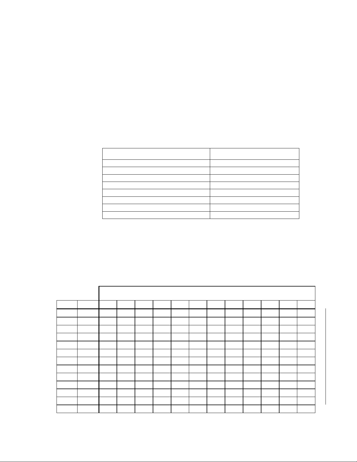
Figure 4.1 presents a detailed view of the front side of the base plate. The circuit
board inside the Type 1 Base Plate includes a large number “1A” in the lower right
corner, as viewed from the front of the base plate, designating it as a Type 1 Base
Plate with a Revision A circuit board. The “1A” designation indicates compatibility
with LonPoint modules such as the DIO-10, that make use of screw terminal 14.
Screw terminal 14 is NOT connected on older base plates marked “1”.
Test points are provided on the circuit board for measuring all of the wiring
connections. Symbols are silk-screened on the PCB to identify the functions of the
test points.
4-2 Installation and Wiring of Base Plates
Page 39
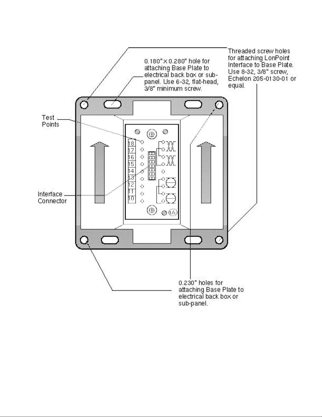
Figure 4.1 LonPoint Type 1 Base Plate - Front Panel
Figure 4.2 shows a detailed view of the rear side of the base plate, the side to which
LonPoint Hardware Guide 4-3
Page 40
wiring connections are made.
Figure 4.2 LonPoint Type 1 Base Plate - Rear Wiring Panel
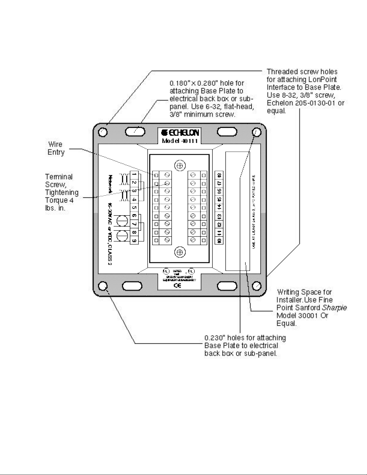
As shown in figure 4.3, the Type 1 Base Plate is intended to be installed in an electrical
box either vertically (base plate interior arrows pointing up) or rotated clockwise 90°
(base plate interior arrows pointing to the right). These two orientations provide optimal
viewing of the front panel legends of an installed LonPoint module, and also
accommodate different methods of installing electrical boxes.
4-4 Installation and Wiring of Base Plates
Page 41
Figure 4.3 LonPoint Type 1 Base Plate Mounting Orientations
Installing A Compatible Electrical Box
Compatible electrical boxes that will accept a Type 1 Base Plate include a 4” square
electrical enclosure (Raco model No. 232, 236, 7232, 7054 or equal), two-gang PVC
switch box (Raco 7834 or equal), and Echelon’s Model 48001 EuroBox for wall or
electrical box applications.
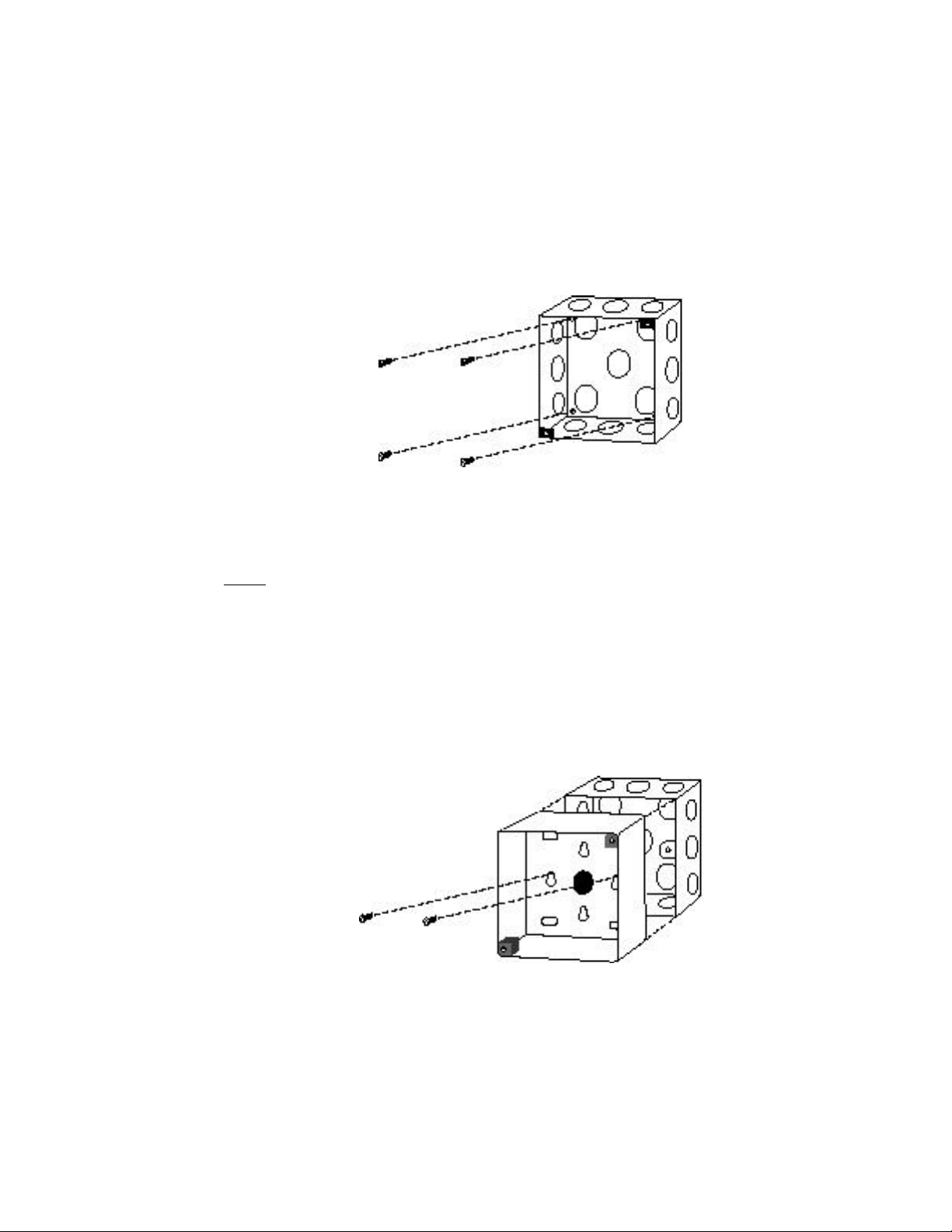
A 4” square electrical enclosures should be either affixed to a wall or to equipment
using suitable mounting screws, or recessed using a suitable mounting clamp (figure
4.4). Due to variations in the location of knock-outs, care must be taken to ensure
that 3/4” conduit fittings do not interfere with the Base Plate when it is installed in
the electrical box; 1/2” conduit fittings have not been found to cause an interference
problem.
LonPoint Hardware Guide 4-5
Page 42

Figure 4.4 4” Square Electrical Box Mounting
There are four mounting options if Echelon’s EuroBox is used. The Eurobox
requires the installer to drill cabling holes: ensure that suitable holes are drilled
prior to mounting. In order to avoid interference with the Base Plate enclosure
walls, all glands and conduit fittings must be located within 1.4”/35cm of the bottom
of the box (as measured from the outside of the box). Wire glands and conduit
fittings must not extend more than 0.63”/16mm into the EuroBox in order to prevent
associated cabling from interfering with the Base Plate screw terminals.
For UK applications, a second mounting option is to affix the EuroBox to a single
gang 25mm BS4662 flush mounting box (MK 866ZIC or similar). Two keyhole slots
are provided in the EuroBox to accomodate the flush mounting box as shown in
figure 4.5. Use screws with flush mounting and ensure that suitable cabling holes
are drilled in the Eurobox prior to mounting, as discussed above.
Figure 4.5 MK Electrical Box Mounting the EuroBox
4-6 Installation and Wiring of Base Plates
Page 43

For continental applications, a third mounting option is to affix the EuroBox to a
recessed 6.5cm diameter plastic DIN box (Kaiser or equal). Two keyhole slots are
provided in the EuroBox to accommodate DIN box mounting, as shown in figure 4.6.
Use the screws provided with the DIN box and ensure that suitable cabling holes are
drilled in the EuroBox prior to mounting.
Figure 4.6 DIN Box Mounting the EuroBox
A fourth mounting option is to affix the EuroBox to 35mm DIN rail using DIN Clips
(one pair included). Two sets of rectangular slots are provided for the DIN clips.
Ensure that the clips provided with each EuroBox lock in place on the box and then
snap them onto the DIN rail (figure 4.7). Ensure that suitable cabling holes are
drilled in the EuroBox prior to mounting.
Figure 4.7 DIN Rail Mounting the EuroBox
The Type 1D DIN Base Plate offers a lower profile and easier access to
wiring terminals for DIN rail applications.
LonPoint Hardware Guide 4-7
Page 44

Connecting Wiring
Route network, power, and input/output cabling into the electrical enclosure using
suitable conduit fittings, bushings, or wire glands. It is good practice to separate the
input/output cabling as much as possible from the network and power cabling,
especially if low level analog signals are being supervised. Once the cabling has been
brought into the electrical enclosure, leave a service loop of 6 inches (15cm) of cable
to simplify wiring the Type 1 Base Plate. Dress the cables using tie wraps or tape to
ensure that the cabling is not compressed or caught when the base plate is screwed
into place.
Strip the cable jacket and wire conductors. The base plate screw terminals will accept
26AWG (0.4mm) to 12AWG (2.2mm) wire, which should be stripped to a length of
0.32” (8mm). Although not required, it may be useful to use a soldering iron to tin the
stripped lengths of any stranded wires to prevent fraying and inadvertent contact
with adjactent terminals. The screw terminal blocks on the real panel of the Type 1
Base Plate are color coded to simplify wiring. The color coding scheme is shown in
table 4.1. The optimum tightening torque for the Type 1 Base Plate screw terminals
is 4 lbs. in. (0.5Nm) maximum. The ideal flathead screwdriver tip width is 0.125”
(3mm).
Terminal Number Terminal Color Function
1 - 4 Orange Network
5 Orange Cable shield, if used
6 - 9 Black Power
10 - 18 Green I/O
Table 4.1 Type 1 Base Plate Terminal Block Color Coding*
* In beta release Type 1 Base Plates, terminals 5 and 14 were
connected together but not connected to any I/O. In Type 1 Base
Plate marked 1A, terminal 5 is floating and may be used to
connect cable shield wires; terminal 14 is reserved for I/O.
Two sets of screw terminals are provided for both the power and network wiring
connections. These connections are internally jumpered on the Type 1 Base Plate
PCB to provide continuity of the network and power wiring, even if no LonPoint
module is installed, as shown figure 4.8. This feature permits the base plate wiring
to be pre-installed and the network and power circuits checked for continuity
throughout the installation, before a single LonPoint module is ever installed. This
feature also prevents network and power interruptions as a result of hot-swapping
LonPoint modules during commissioning or service operations. Finally, providing
two sets of screw terminals permits incoming and outgoing wiring to be landed at
separate screw terminals without the need to insert more than one wire in any given
screw terminal.
4-8 Installation and Wiring of Base Plates
Page 45

1 2 3 4 5 6 7 8 9
Network
16-30VAC or VDC
Figure 4.8 Base Plate Power and Network Wiring Connections
See chapters 5 through 9 for specific I/O wiring connections.
LonPoint Type 1D DIN Base Plate Installation
Figure 4.9 presents a detailed view of the front side of the base plate. The circuit
board inside the Type 1D DIN Base Plate includes an arrow with the designation
"1A," designating it as a Type 1 Base Plate with a Revision A circuit board. The 1D
Base Plate is intended to be installed either on a 35mm DIN rail, or using the
integral keyhole slots, on a wall or panel. Two arrows indicates the vertical
orientation of the Base Plate that will provide the best viewing of the front panel
legends.
LonPoint Hardware Guide 4-9
Page 46

Wire entry
points
flathead
Terminal screw,
tightening torque 4lbs.
in. (0.5Nm) maximum
18 17 16 15 13 12 11 1014
CAUTION
18 17 16 15 14 13 12 11 10
I/O
Keyhole slot for wall
or panel mounting
1A
Threaded screw holes for
attaching LonPoint
modules to the Base Plate.
Use 8-32, 3/8" screw,
Echelon 205-0130-01 or
equal
Network
1 2 3
4
5 6 7 8 9
Jumper Plug
storage location remove before
1 2 3 4 6 7 8 95
installing LonPoint
Module
DIN rail release activate with
Jumper Plug
insertion
Figure 4.9 Front Side of Type 1D DIN Base Plate
4-10 Installation and Wiring of Base Plates
Page 47

The base plate contains two integral DIN rail tabs that securely grab a 35mm DIN
rail onto which the base plate is mounted. The base plate may be used on both
35mm x 7.5mm and 35mm x 15mm DIN rails. To release the Base Plate from the
DIN rail, sequentially insert a flathead screwdriver into the DIN rail release tabs
and gently pull away from the DIN rail (figure 4.10).
Four keyhole slots are provided for affixing the Type 1D DIN Base Plate to a wall or
panel (figure 4.11).
The 1D Base Plate is supplied with a jumper plug that connects the power and
network connections between adjacent base plates. The Jumper Plug is shipped
inserted into the main cavity of the Base Plate, and can be removed by gently
pulling the plug handle in the direction of the mounting arrow. The Jumper Plug
must be removed before a LonPoint module can be inserted into the Base Plate.
Figure 4.10 DIN Rail Base Plate Dimensions (Dimensions are in mm (inches).)
LonPoint Hardware Guide 4-11
Page 48
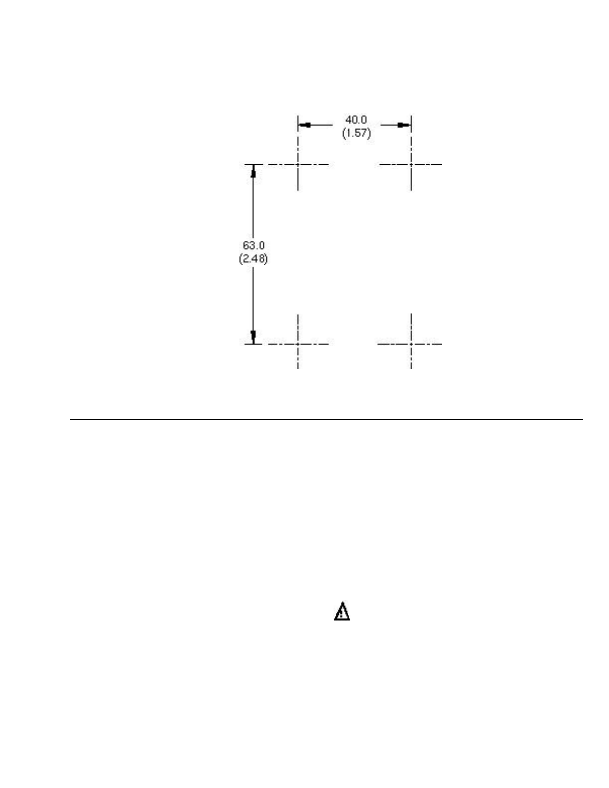
Figure 4.11 Mounting Holde Pattern Dimensions for Type1D Base Plates
Connecting Wiring
Route all network, power, and input/output cabling to the pertinent screw terminals
located at the top and bottom of the Base Plate. It is good practice to separate the
input/output cabling as much as possible from the network and power cabling,
especially if low-level analog signals are being supervised.
Strip the cable jacket and wire conductors. The base plate screw terminals will
accept 24AWG (0.5mm) to 12AWG(2.2mm) wire, which should be stripped to a
length of 0.32" (8mm). Although not required, it may be useful to use a soldering
iron to tin the stripped lengths of any strand wired to prevent fraying and
inadvertent contact with adjacent terminals. Identifying screw terminal numbers
are conveniently located both above and below each screw terminal. Symbols and/or
language identifying the function of the screw terminals also are provided.
Note that terminals 1 and 9 are numbered from left to right, but terminals 10 to 18
are numbered from right to left.
The optimum tightening torque for the screw terminals is approximately 4 pounds
(0.5Nm). The ideal flathead screwdriver tip width is 3/32" (2.5mm).
4-12 Installation and Wiring of Base Plates
Page 49
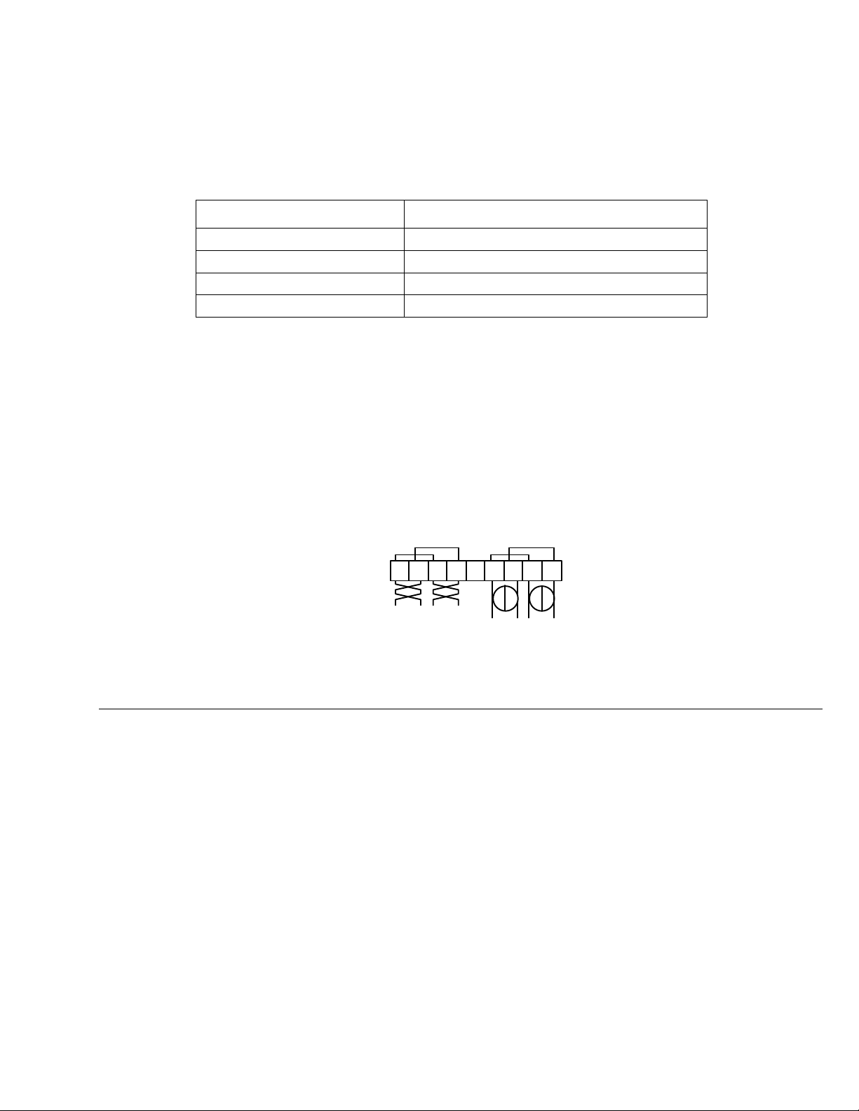
Table 4.2 Type 1D Base Plate Terminal Block Connections
Network
16-30VAC or VDC
Terminal Number Function
1 -4 Network
5 Cable shield, if used
6 - 9 Power
10 - 18 I/O
Two sets of screws are provided for both the power and network wiring connections.
These connections are internally jumpered on the Type 1D Base Plate PCB to
provide continuity of the network and power wiring, even if no LonPoint module is
installed, as shown in figure 4.12. This feature permits the base plate wiring to be
pre-installed and the network and power circuits checked for continuitiy throughout
the installation, before a single LonPoint module is ever installed. This feature also
prevents network and power interruptions as a result of hot swapping LonPoint
modules during commissioning or service operations. Finally, providing two sets of
screw terminals permits incoming and outgoing wiritng to be landed at separate
screw terminals without the need to insert more than one wire in any given screw
terminal.
1 2 3 4 5 6 7 8 9
Figure 4.12 Base Plate Power and Network Wiring Connections
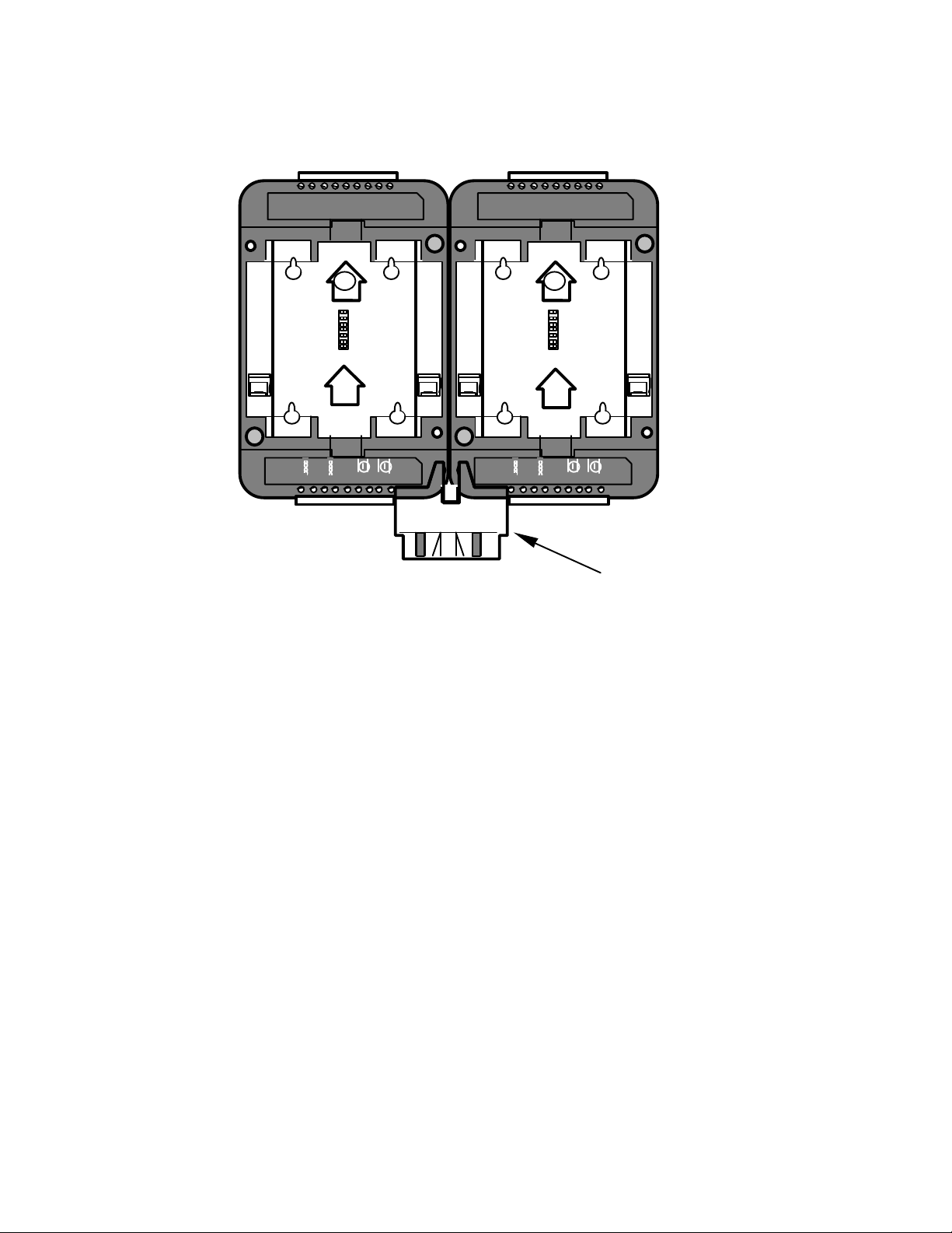
Connecting the Jumper Plug(s)
From time to time it may be necessary to mount two or more LonPoint Type 1D or
2D Base Plates adjacent to one another. In these instances, power and network
wiring must be daisy-chained between each Base Plate. Routing power and network
wiring between multiple base plates can be a laborious and time consuming task,
and there is always the risk of a wiring error. For this reason, the Type 1D and 2D
Base Plates are each supplied with a Jumper Plug and Jumper Plug connecotrs
which simply and easily bus the power and network between adjacent Base Plates.
The Jumper Plug connectors are located on either side of the terminal block with
connections 1 to 9 . The Jumper Plug connectors are wired in parallel with the
network and power connections on the screw terminals. When two Base Plates are
mounted adjacent to each other, with the mounting arrows pointing in the same
direction, the Jumper Plug connectors will be aligned such that a Jumper Plug may
be inserted into the two connectors, thus bridging power and network between the
two Base Plates (figure 4.13).
LonPoint Hardware Guide 4-13
Page 50
18 171615141312111
Jumper Plug (x-ray view)
0
1A 1A
18 171615141312111
0
1 23456 7
8 9
1 23456 7
8 9
Figure 4.13 Mounting Two Base Plates with Jumper Plug Connectors
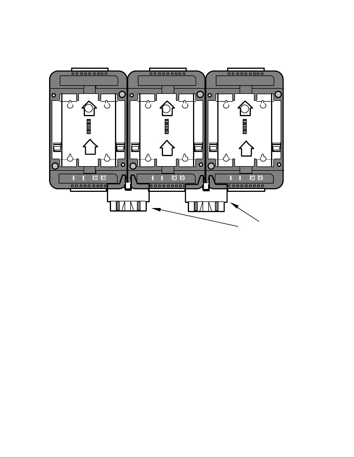
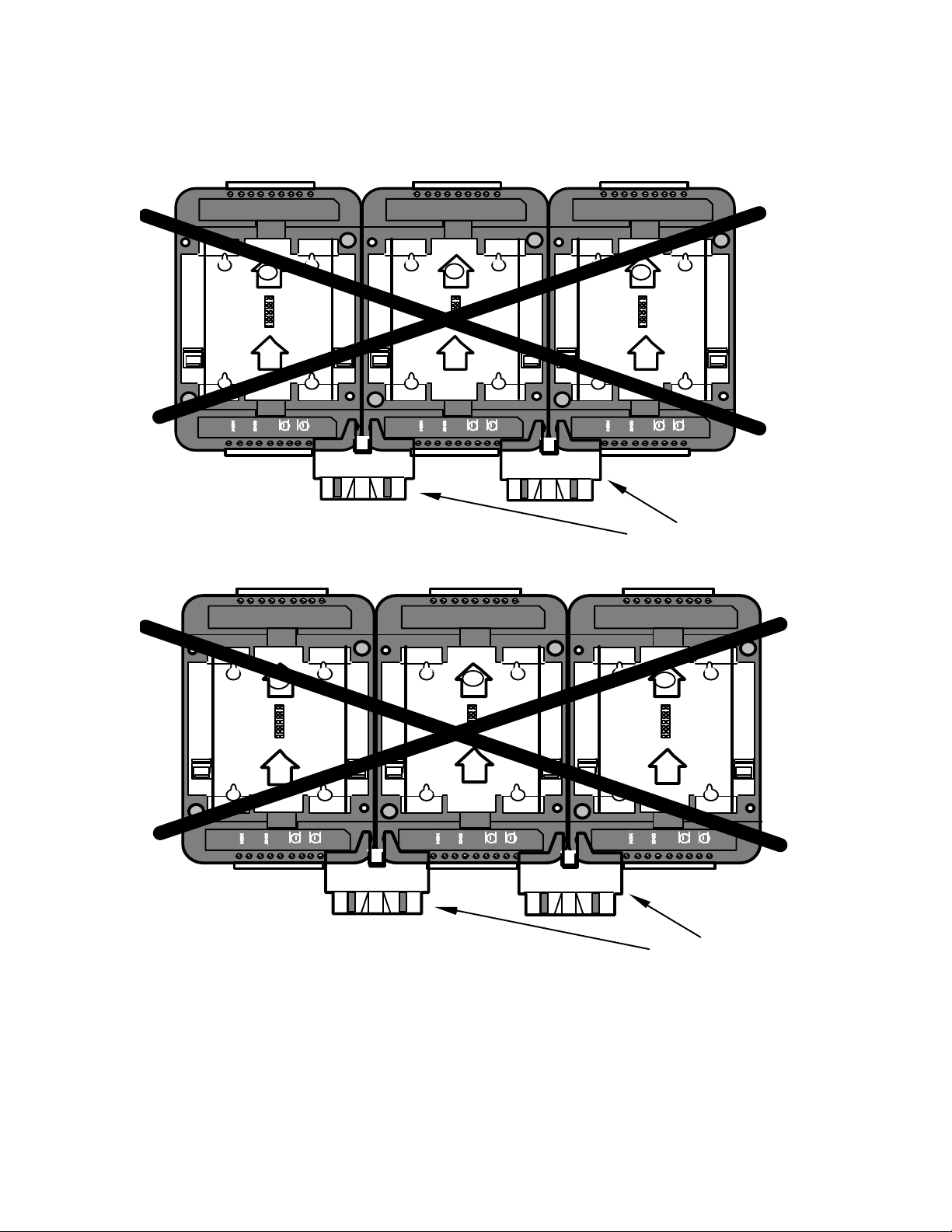
When used with a Type 2D Base Plate, there are restrictions about the placement of
the Type 2D Base Plates (and the routers they contain) relative to the adjacent Type
1D Base Plates. In all cases, any Type 2D Base Plates must be located to the left
side of any Type 1D Base Plates (figure 4.14) with which they will share a common
channel.
4-14 Installation and Wiring of Base Plates
Page 51
Jumper Plugs (x-ray view)
Type 2D Type 1D Type 1D
18 171615141312111
0
2 1A
1 2 3 4 5 6 7 8 9
Figure 4.14 Mixing Type 1D and Type 2D Base Plates
18 171615141312111
1 2 3 4 5 6 7 8 9
0
18 171615141312111
0
1A
1 2 3 4 5 6 7 8 9
The reason for this limitation is that only the right Jumper Plug connector on a
Type 2D Base Plate bridges the network connection; the left Jumper Plug connector
on a Type 2D Base Plate bridges only the power connection. This arrangement
permits several routers, each with a different channel type, to be mounted on a
common DIN rail and share a common power supply. Figure 4.15 shows mounting
configurations that are problematic and must be avoided because the router will
be unable to communicate with the other LonPoint modules via the Jumper Plug.
If such a mounting arrangement must tbe used, then the base plates must be
interconnected using wiring instead of the Jumper Plug.
LonPoint Hardware Guide 4-15
Page 52
Jumper Plugs (x-ray view)
Type 1D Type 2D Type 1D
Jumper Plugs (x-ray view)
18 171615141312111
1A
1 2 3 4 5 6 7 8 9
Type 1D
18 171615141312111
0
18 171615141312111
0
2
1 2 3 4 5 6 7 8 9
Type 1D
0
18 171615141312111
0
18 171615141312111
1A
1 2 3 4 5 6 7 8 9
Type 2D
18 171615141312111
0
0
1A
1 2 3 4 5 6 7 8 9
1A
1 2 3 4 5 6 7 8 9
2
1 2 3 4 5 6 7 8 9
Figure 4.15 Problematic Mounting Configurations when Using Routers
4-16 Installation and Wiring of Base Plates
Page 53

LonPoint Type 2 Base Plate Installation
All LonPoint LPR Routers may be installed in either a Type 2 Base Plate (Model
40222) or a Type 2D DIN Base Plate (Model 48222). Figure 4.16 presents a detailed
view of the front side of the Base Plate. The circuit board inside the Type 2 Base
Plate includes a large number “2” in the lower right corner, as viewed from the front
of the base plate, designating it as a Type 2 Base Plate. Test points are provided on
the circuit board for measuring all of the wiring connections; symbols are silkscreened on the PCB to identify the functions of the test points.
LonPoint Hardware Guide 4-17
Page 54
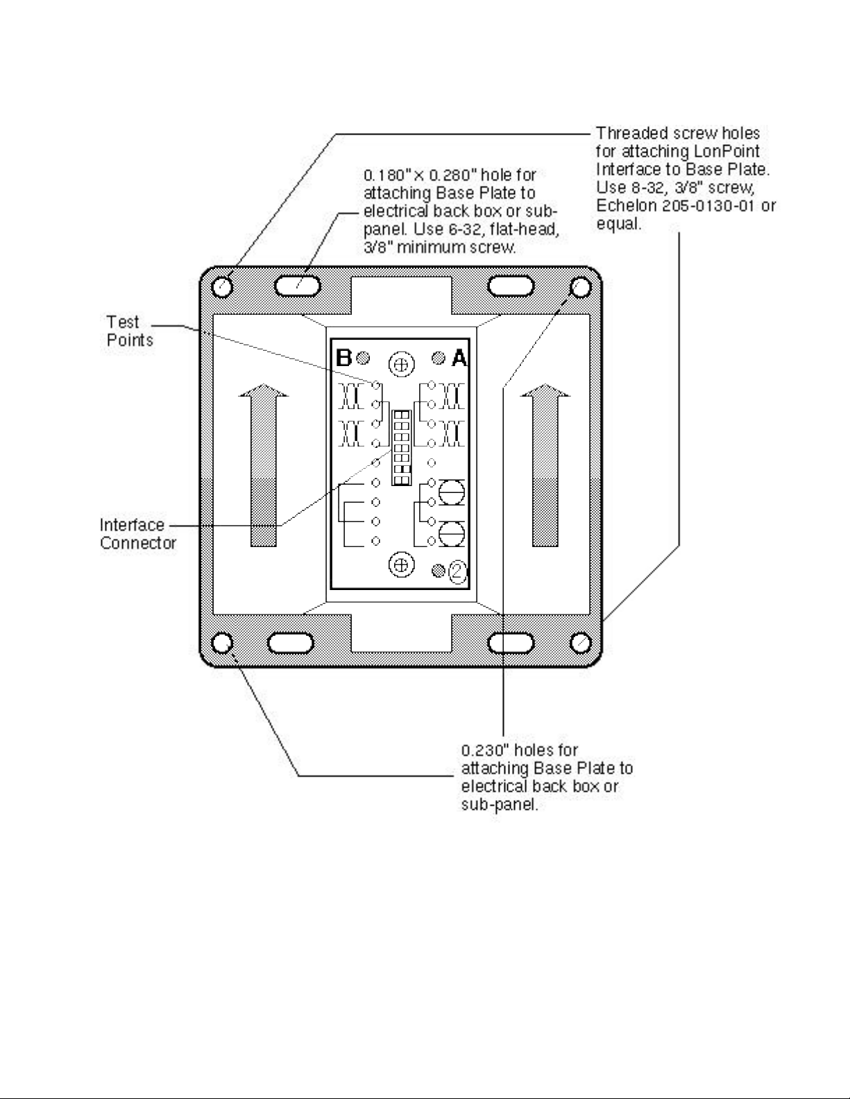
Figure 4.16 LonPoint Type 2 Base Plate - Front Panel
4-18 Installation and Wiring of Base Plates
Page 55
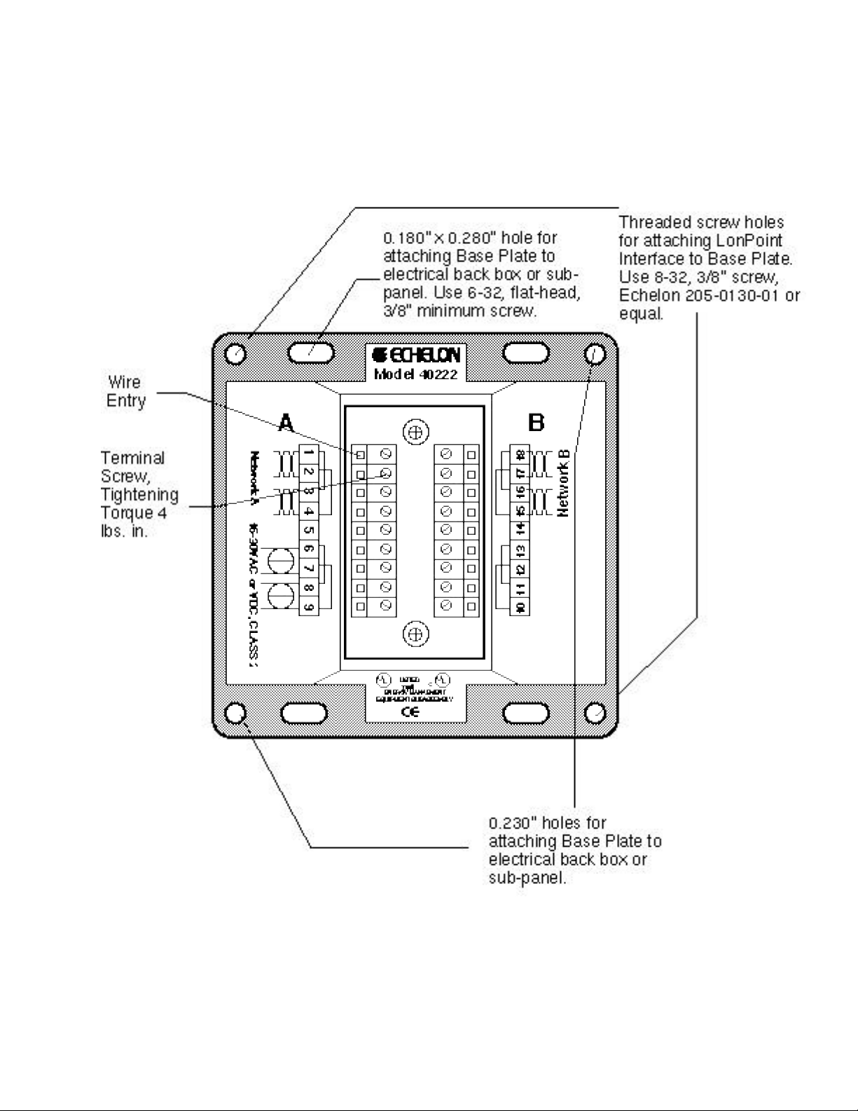
Figure 4.17 shows a detailed view of the rear side of the Base Plate, the side to
which wiring connections are made.
Figure 4.17 LonPoint Type 2 Base Plate - Rear Wiring Panel
LonPoint Hardware Guide 4-19
Page 56

As shown in figure 4.18, the Type 2 Base Plate is intended to be installed in an electrical
box either vertically (base plate interior arrows pointing up) or rotated clockwise 90°
(base plate interior arrows pointing to the right). These two orientations provide
optimal viewing of the front panel legends of an installed LonPoint module, and also
accommodate different methods of installing electrical boxes.
Figure 4.18 LonPoint Type 2 Base Plate Mounting Orientations
Installing A Compatible Electrical Box
Compatible electrical boxes that will accept a Type 2 Base Plate include a 4” square
by 2” deep electrical enclosure (Raco model No. 232, 236, 7232, 7054 or equal), two-
4-20 Installation and Wiring of Base Plates
Page 57
gang PVC switch box (Raco 7834 or equal), and Echelon’s Model 48001 EuroBox for
wall and 35mm DIN rail applications.
A 4” square electrical enclosures should be either affixed to a wall or to equipment using
suitable mounting screws, or recessed using a suitable mounting clamp (figure 4.19). Due
to variations in the location of knock-outs, care must be taken to ensure that 3/4” conduit
fittings do not interfere with the Base Plate when it is installed in the electrical box; 1/2”
conduit fittings have not been found to cause an interference problem.
Figure 4.19 4” Square Electrical Box Mounting
There are four mounting options if Echelon’s EuroBox is used. The Eurobox
requires the installer to drill cabling holes: ensure that suitable holes are drilled
prior to mounting. In order to avoid interference with a Type 1 or Type 2 Base
Plate, all glands and conduit fittings must be located within 1.4”/35cm of the bottom
of the box (as measured from the outside of the box). Wire glands and conduit
fittings must not extend more than 0.63”/16mm into the EuroBox in order to prevent
associated cabling from interfering with the Base Plate screw terminals.
For UK applications, a second mounting option is to affix the EuroBox to a single
gang 25mm BS4662 flush mounting box (MK 866ZIC or similar). Two keyhole slots
are provided in the EuroBox to accomodate the flush mounting box as shown in
figure 4.20. Use screws with flush mounting and ensure that suitable cabling holes
are drilled in the Eurobox prior to mounting, as discussed above.
Figure 4.20 MK Electrical Box Mounting the EuroBox
LonPoint Hardware Guide 4-21
Page 58

A third mounting option is to affix the EuroBox to a recessed 6.5cm diameter plastic
DIN box (Kaiser or equal). Two keyhole slots are provided in the EuroBox to
accommodate DIN box mounting, as shown in figure 4.21. Use the screws provided
with the DIN box and ensure that suitable cabling holes are drilled in the EuroBox
prior to mounting.
Figure 4.21 DIN Box Mounting the EuroBox
A fourth mounting option is to affix the EuroBox to 35mm DIN rail using DIN Clips
(one pair included). Two sets of rectangular slots are provided for the DIN clips.
Ensure that the clips lock in place on the EuroBox and then snap them onto the DIN
rail (figure 4.22). Ensure that suitable cabling holes are drilled in the EuroBox prior
to mounting.
Figure 4.22 DIN Rail Mounting the EuroBox
The Type 2D DIN Base Plate offers a lower profile and easier access to wiring
terminals for 25mm DIN rail applications.
4-22 Installation and Wiring of Base Plates
Page 59

Connecting Wiring
Since a Type 2 Base Plate is designed for use with an LPR Router, the only cabling
that will be connected to the Base Plate is power and the network cables for the two
channels between which the router is connected. Bring the cabling into the electrical
enclosure using suitable conduit fittings, bushings, or wire glands, and be sure to
leave a service loop of 6 inches (15cm) of cable to simplify wiring the Type 2 Back
Plate. Dress the cables using tie wraps or tape to ensure that the cabling is not
compressed or caught when the base plate is screwed into place.
Strip the cable jacket and wire conductors. The base plate screw terminals will
accept 24AWG (0.5mm) to 12AWG (2.2mm) wire, which should be stripped to a
length of 0.32” (8mm). Although not required, it may be useful to use a soldering
iron to tin the stripped lengths of any stranded wires to prevent fraying and
inadvertent contact with adjactent terminals. The screw terminal blocks on the rear
panel of the Type 2 Base Plate are color coded to simplify wiring. The color coding
scheme is shown in table 4.3. The optimum tightening torque for the Type 1 Base
Plate screw terminals is 4 lbs. in. (0.5Nm) maximum. The proper screwdriver tip
width is 0.125” (3mm).
Terminal Number Terminal Color Function
1 - 4 Orange Network A
5 Orange Cable shield, if used, internally
6 - 9 Black Power
10 and 12 Black None
11 and 13 Black None
14 Orange Cable shield, if used, internally
15 - 18 Orange Network B
Table 4.3 Type 2 Base Plate Terminal Block Color Coding
connected to terminal 14
Jumpered together internally may be used to land extra wires
Jumpered together internally may be used to land extra wires
connected to terminal 5
Two sets of screw terminals are provided for both the power and network wiring
connections. These connections are internally jumpered on the Type 2 Base Plate
PCB to provide continuity of the network and power wiring, even if no LonPoint
Router module is installed. This feature permits the Base Plate wiring to be preinstalled and the network and power circuits checked for continuity throughout the
installation, before a single LonPoint module is ever installed. This feature also
prevents network and power interruptions as a result of hot-swapping LonPoint
modules during commissioning or servicing operations. Finally, providing two sets of
screw terminals permits incoming and outgoing wiring to be landed at separate
screw terminals without the need to insert more than one wire in any given screw
terminal, which improves wiring reliability.
LonPoint Hardware Guide 4-23
Page 60

LonPoint Type 2D DIN Base Plate Installation
Figure 4.23 presents a detailed view of the front side of the base plate. The circuit
board inside the Type 2D DIN Base Plate includes an arrow with the designation
"2." The 2D Base Plate is intended to be installed either on a 35mm DIN rail or,
using the integral keyhole slots, on a wall or panel. An arrow indicates the vertical
orientation of the base plate which will provide the base viewing of the front panel
legends of an installed LonPoint module.
4-24 Installation and Wiring of Base Plates
Page 61

18 17 16 15 14 13 12 11 10
Network
B
18 17 16 15 14 13 12 11 10
2
Front View
Network
1 2
A
1 2 3 4 5 6 7 8 9
3 4 5 6 7 8 9
Jumper Plug
(one supplied with
each DIN Base
Plate)
Figure 4.23 Front View of the Type 2D DIN Base Plate
LonPoint Hardware Guide 4-25
Page 62

The base plate contains two integral DIN rail locks which securely grab a 35mm
DIN rail onto which the base plate is mounted. The Base Plate may be used on both
35mm x 7.5mm and 35mm x 15mm DIN rails. To release the Base Plate from the
DIN rail, sequentially insert a flathead screwdriver into each DIN rail release tabs
and gently pull away from the DIN rail (figure 4.24).
Four keyhole slots are provided for affixing the Type 2D DIN Base Plate to a wall or
panel (figure 4.25).
The 2D Base Plate is supplied with a Jumper Plug that connects the power and
network connections between adjacent base plates. The Jumper Plug is shipped
inserted into the main cavity of the Base Plate, and can be removed by gently
pulling the plug handle in the direction of the mounting arrow. The Jumper Plug
must be removed before a LonPoint Router can be inserted into the Base Plate.
Figure 4.24 DIN Rail Base Plate Dimensions (Dimensions are in mm (inches).)
4-26 Installation and Wiring of Base Plates
Page 63

Figure 4.25 Mounting Hole Pattern Dimensions for Type 2D Base Plates
Connecting Wiring
Route all network and power cabling to the pertinent screw terminals located at the
top and bottom of the Base Plate. It is good practice to separate any nearby
input/output cabling as much as possible from the network and power cabling,
especially if low-level analog signals are being supervised.
Strip the cable jacket and wire conductors. The base plate screw terminals will
accept 24AWG (0.5mm) to 12AWG (2.2mm) wire, which should be stripped to a
length of 0.32" (8mm). Although not required, it may be useful to use a soldering
iron to tin the stripped lengths of any stranded wire to prevent fraying and
inadvertent contact with adjacent terminals. Identifying screw terminal numbers
are conveniently located both above and below each screw terminal. Symbols and/or
language identifying the function of the screw terminals also are provided.
Note that terminals 1 to 9 are numbered from left to right, but terminals 10 to 18
are numbered from right to left.
The optimum tightening torque for the screw terminals is approximately 4 pounds
(0.5Nm). The ideal flathead screwdriver tip width is 3/32" (2.5mm).
LonPoint Hardware Guide 4-27
Page 64
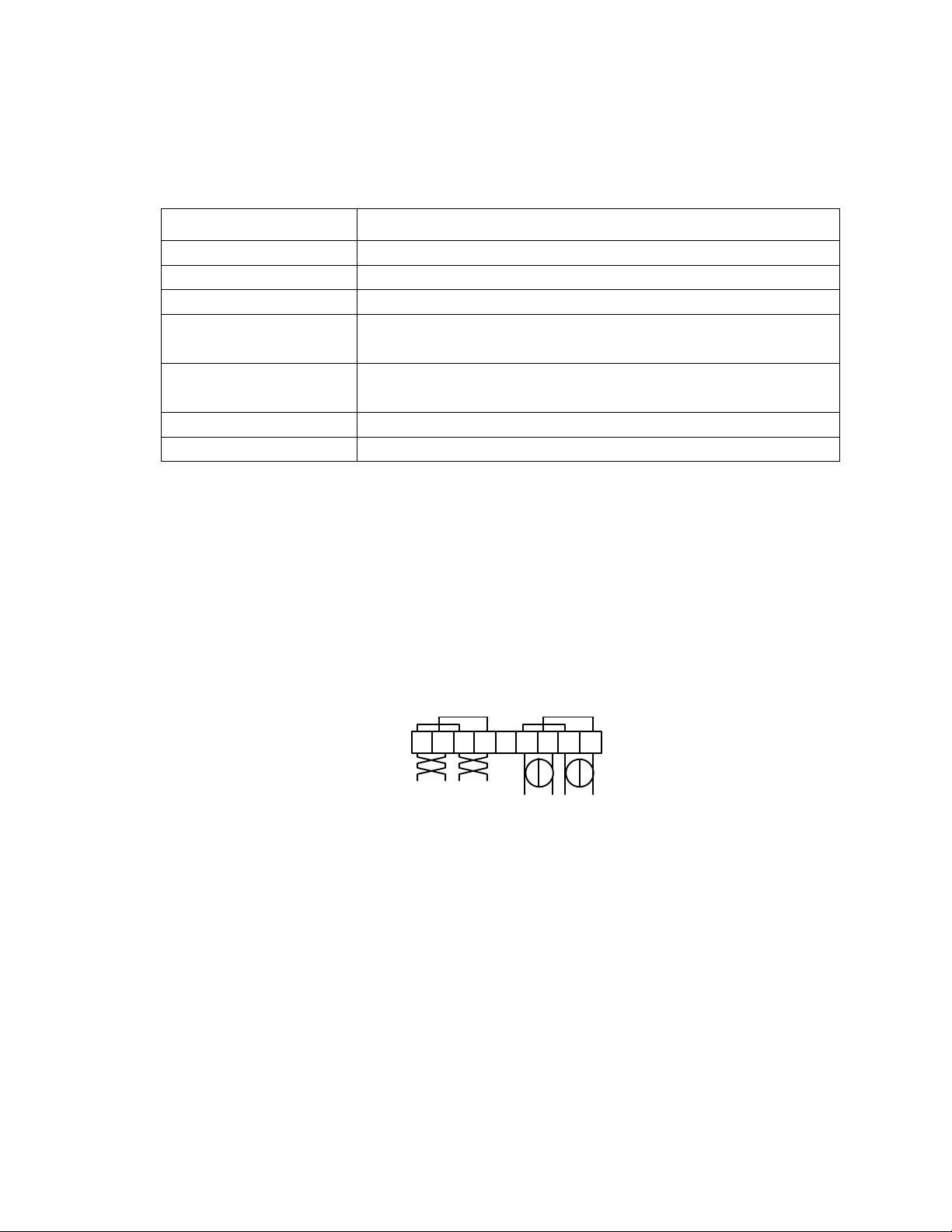
Table 4.4 Type 2D Base Plate Terminal Block Connections
16-30VAC or VDC
Terminal Number Function
1 -4 Network A
5 Cable shield, if used, internally connected to terminal 14
6 - 9 Power
10 and 12 None
Jumpered together internally, may be used to land extra wires
11 and 13 None
Jumpered together internally, may be used to land extra wires
14 Cable shield, if used, internally connected to terminal 5
15 - 18 Network B
Two sets of screws are provided for both the power and network wiring connections.
These connections are internally jumpered on the Type 2D Base Plate PCB to
provide continuity of the network and power wiring, even if no LonPoint module is
installed, as shown in figure 4.26. This feature permits the Base Plate wiring to be
pre-installed and the network and power circuits checked for continuity throughout
the installation, before a single LonPoint module is ever installed. This feature also
prevents network and power interruptions as a result of hot-swapping LonPoint
modules during commissioning or service operations. Finally, providing two sets of
screw terminals permits incoming and outgoing to be landed at separate screw
terminals without the need to insert more than one wire in any given screw
terminal.
1 2 3 4 5 6 7 8 9
Network
Figure 4.26 Base Plate Power and Network Wiring Connections
4-28 Installation and Wiring of Base Plates
Page 65
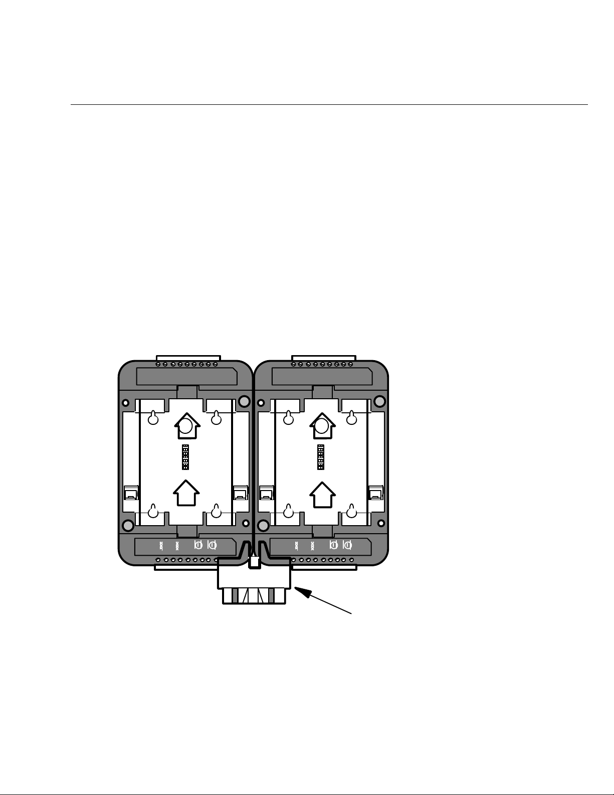
Connecting the Jumper Plug(s)
Jumper Plug (x-ray view)
From time to time it may be necessary to mount two or more LonPoint Type 1D or
2D Base plates adjacent to one another. When this happens, power and network
wiring must be daisy-chained between each Base Plate. Routing power and
network wiring between multiple Base Plates can be a laborious and time
consuming task, and there is always the risk of a wiring error. For this reason, the
Type 1D and 2D Base Plates are each supplied with a Jumper Plug and Jumper
Plug connectors which simply and easily bus the power and network between
adjacent Base Plates.
The Jumper Plug connectors are located on either side of the terminal block with
connections 1 to 9. The Jumper Plug connectors are wired in parallel with the
network and power connections on the screw terminals. When two base plates are
mounted adjacent to each other, with the mounting arrows pointing in the same
direction, the Jumper Plug connectors will be aligned such that a Jumper Plug may
be inserted into the two adjacent connectors thus bridging power and network
between the two Base Plates (figure 4.27).
18 171615141312111
2
1 23456 7
8 9
0
18 171615141312111
2
1 23456 7
8 9
0
Figure 4.27 Jumper Plug Insertion Points for Type 2D Base Plates
LonPoint Hardware Guide 4-29
Page 66
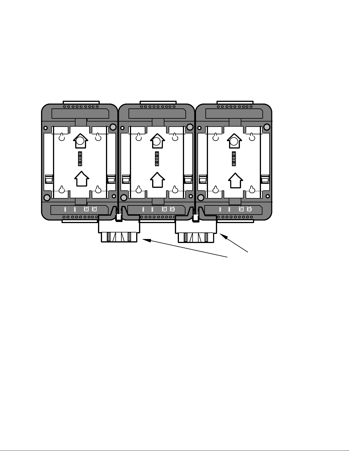
There are restrictions about the placement of a Type 2D Base Plate relative to other
Jumper Plugs (x-ray view)
Type 1D or Type 2D Base Plates to which it will be connected via Jumper Plugs. In
all cases, any Type 2D Base Plates must be located to the left side of other Type 2D
Base Plates (figure 4.28).
Type 2D Type 1D Type 1D
18 171615141312111
0
2 1A
1 2 3 4 5 6 7 8 9
18 171615141312111
1 2 3 4 5 6 7 8 9
0
18 171615141312111
1A
1 2 3 4 5 6 7 8 9
Figure 4.28 Locate the Type 2D Base Plate to the Left of Type 1D Base Plates
0
Type 1D Base Plates must be located to the right of any router in a Type 2D Base
Plate with which they share a common channel. The reason for this limitation is
that only the right Jumper Plug connector on a Type 2D Base Plate bridges the
network connection, the left Jumper Plug connector on a Type 2D Base Plate bridges
only the power connection. This arrangement permits several routers, each with a
different channel type, to be connected to a common power supply. Figure 4.29
shows mounting configurations that are problematic and must be avoided because
the router will be unable to communicate with the other LonPoint modules.
4-30 Installation and Wiring of Base Plates
Page 67
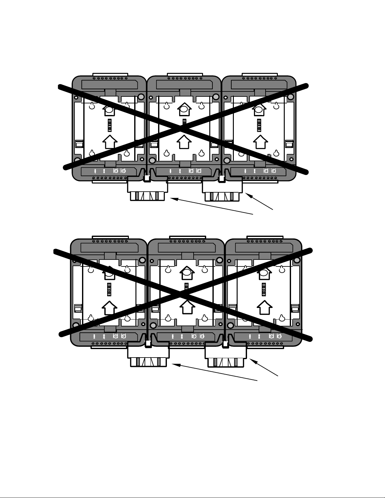
Jumper Plugs (x-ray view)
Type 1D Type 2D Type 1D
Jumper Plugs (x-ray view)
18 171615141312111
1A
1 2 3 4 5 6 7 8 9
Type 1D
18 171615141312111
0
18 171615141312111
0
2
1 2 3 4 5 6 7 8 9
Type 1D
0
18 171615141312111
0
18 171615141312111
1A
1 2 3 4 5 6 7 8 9
Type 2D
18 171615141312111
0
0
1A
1 2 3 4 5 6 7 8 9
1A
1 2 3 4 5 6 7 8 9
2
1 2 3 4 5 6 7 8 9
Figure 4.29 Problematic Mounting Configurations when Using Routers
LonPoint Hardware Guide 4-31
Page 68

4-32 Installation and Wiring of Base Plates
Page 69

5
Installing the DI-10 Digital Input Module
This chapter describes the process of installing the Model 41100 DI-10
Digital Input Module.
LonPoint Hardware Guide 5-1
Page 70
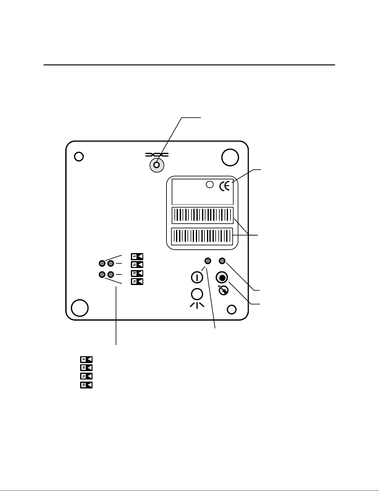
LonPoint DI-10 Digital Input Module
L
o
n
P
o
i
n
t
™
I
n
t
e
r
f
a
c
e
Digital Input 4 LED
4
The front panel of the DI-10 module is shown in figure 5.1. There are no userconfigured jumper blocks or other adjustable controls on the DI-10 module. A
separate front panel LED is provided for each intput.
Network Access Jack; Use
With Echelon PCC-10 Cable
Model 78303
LonPoint Interface
E
1
2
3
4
DI-10
MODEL 41100 972
SW VERSION 3.0
ID NUMBER
INPUT: 0-32VDC
DI-10 MODEL 41100 ID NUMBER
DI-10 MODEL 41100 ID NUMBER
U
®
c us
L
m
LISTED 178K
ENERGY MANAGEMENT
EQUIPMENT SUBASSEMBLY
Model and Software
Revision
Peel-Off Code 39
Format Bar Code of
LonPoint Interface
Neuron Chip ID
Number
Service LED
Service Switch
Power/Wink LED:
Power ON: Illuminated Continuously
Digital Input Status LEDs
1
2
3
Digital Input 1 LED
Digital Input 2 LED
Digital Input 3 LED
Figure 5.1 LonPoint DI-10 Digital Input Module - Front Panel
Wink: Flashing
5-2 Installing the DI-10 Digital Input Module
Page 71

The DI-10 module is installed in a Type 1 or Type 1D Base Plate. Wiring connections
to the DI-10 module are presented in table 5.1. Specifications for the DI-10 module
are shown in table 5-2.
Table 5.1 DI-10 Digital Input Module Wiring Connections
Screw Terminal Wiring Connection
1 and 2 Incoming network wiring, TP/FT-10 channel, polarity-
insensitive
3 and 4 Outgoing network wiring, TP/FT-10 channel, polarity-
insensitive
5 Unused
6 and 7 Incoming power wiring, 16-30VAC or VDC, 2.2VA, polarity-
insensitive. If using DC power, it is good practice to maintain
continuity of the power polarity throughout the network:
terminals 6 and 8 should be the same polarity, and terminals
7 and 9 should be the same polarity.
10 + input of digital input 1
11 - input of digital input 1 (common to all inputs)
12 + input of digital input 2
13 - input of digital input 2 (common to all inputs)
14 Unused
15 + input of digital input 3
16 - input of digital input 3 (common to all inputs)
17 + input of digital input 4
18 - input of digital input 4 (common to all inputs)
Table 5.2 LonPoint DI-10 Digital Input Module Specifications
Function Description
Processor/memory Neuron 3150 Chip, 10MHz, 56K flash memory
Service function Recessed service switch, service LED, power/wink LED.
Dual tear-off bar-code Neuron ID self-adhesive tag for
application to red-line drawings in the field
I/O 4 digital inputs, 0-32VDC or dry contact; 2.5V input logic
threshold; separate status LEDs for each input
I/O isolation 100V, transformer isolation. Inputs are isolated from the input
power and the network but not from each other.
Transceiver type FTT-10A with blocking capacitors for compatibility with link
power channel
Network connector Phone plug connector accessible from front panel
Input power 16-30VAC or VDC @ 2.2VA, internally isolated power supply
Mounting Type 1 or Type 1D Base Plate
Temperature -40 to +85°C, operating and non-operating
LonPoint Hardware Guide 5-3
Page 72

Humidity 10 to 95% RH @ 50°C
EMI FCC A, CE Mark
Safety agency UL 916
Function Blocks Node object (1), digital input open-loop sensor objects (4),
digital encoder controller objects (2), analog function block
controller objects (4), type translators (6)
Software Configuration Wide variety of LONMARK Standard Configuration Parameter
Types supported by direct memory read/write function of LNS
compatible network management tools
DI-10 Module Software Settings
The software settings of the DI-10 module are described in the LonPoint Application
and Plug-In Guide.
Installing the DI-10 Module
Installation of the DI-10 module involves the following steps:
1. Ensure that the Type 1 or Type 1D Base Plate has been wired and installed
correctly.
2. Check for continuity on all network and power wiring. Ensure that the correct
sensors are connected to the correct Base Plate I/O terminals.
3. Make certain that all network channels are terminated with the correct number
and type of Terminator.
4. Insert the DI-10 module into the Base Plate by aligning the network access jack
on the DI-10 with the arrow head on the Base Plate (the arrow should point in
the direction of the jack), and then pressing firmly to ensure that the module is
properly seated in its mating Base Plate connector.
5. The DI-10 module can be hot-plugged: there is no need to disconnect power
when installing the module. If power is present then the Power LED will
illuminate continuously. If power is not present then the Power LED will remain
off.
6. Securely attach the DI-10 module to the Base Plate by screwing the two Echelon
205-0130-01 screws (8-32 [M8], 3/8” [9.5mm]) into the threaded inserts in the
Base Plate. Use approximately 4 lbs. in. (0.5Nm) torque on the screws.
7. Follow the node configuration procedure described in the LonPoint Application
and Plug-In Guide to configure the software in the DI-10 module.
8. See Troubleshooting for assistance with improper DI-10 module operation.
5-4 Installing the DI-10 Digital Input Module
Page 73

Installing the DIO-10 Digital
Input/Output Modules
This chapter describes the process of installing the Model 41500
DIO-10 Digital Input/Output Modules.
6
Installing the DIO-10 Input/Output Modules 6-1
Page 74

LonPoint DIO-10 Digital Input/Output Modules
L
o
n
P
o
i
n
t
™
I
n
t
e
r
f
a
c
e
Digital Input 2 LED
2
The front panel is shown in figure 6.1. There are no user-configured jumper blocks on
the DIO-10 module. A separate front panel LED is provided for each input, and a
Hand/Off/Auto switch and LED are provided for each output.
The four hand/off/auto switches control the outputs of the DIO-10 as long as the module
is powered, regardless of the software state of the module. The four status LEDs will
track the state of the outputs only if the application program is running and the module
is in the configured state. The status LEDs will not fuction if the module is in an unconfigured state.
HAND/OFF/AUTO Switches
(manual) (network)
Network Access Jack; Use
With Echelon PCC-10 Cable
Model 78303
LonPoint Interface
E
U
c
L
®
DIO-10
MODEL 41500 9820
SW VERSION 3.0
ID NUMBER
INPUT: 0-32VDC
1 2
1 2 3 4
DIO-10 MODEL 41500 ID NUMBER
DIO-10 MODEL 41500 ID NUMBER
m
us
LISTED 178K
ENERGY MANAGEMENT
EQUIPMNT SUBASMBLY
OUTPUT: 30V AC/DC, 2A
Model and Software
Revision
Peel-Off Code 39
Format Bar Code of
LonPoint Interface
Neuron Chip ID
Number
1
2
1
2
Service LED
Service Switch
Digital Input Status LEDs
1
2
1
Digital Input 1 LED
Digital Input 2 LED
Digital Input 1 LED
Figure 11.1 LonPoint DIO-10 Digital Input/Output Module - Front Panel
Power/Wink LED:
Power ON: Illuminated Continuously
Wink: Flashing
6-2 Installing the DIO-10 Input/Output
Modules
Page 75

The DIO-10 module is intalled in a Type 1 or Type 1D Base Plate. Wiring connections to the
DIO-10 module are presented in table 6.1. Specifications for the DIO-10 module are shown in
table 6.4.
Table 6.1 DIO-10 Digital Input/Output Module Wiring Connections
Screw Terminal Wiring Connection
1 and 2 Incoming network wiring, TP/FT-10 channel, polarity-
insensitive
3 and 4 Outgoing network wiring, TP/FT-10 channel, polarity-
insensitive
5 Unused
6 and 7 Incoming power wiring, 16-30VAC or VDC, 4.75VA, polarity-
insensitive. If using DC power, it is good practice to maintain
continuity of the power polarity throughout the network:
terminals 6 and 8 should be the same polarity, and terminals
7 and 9 should be the same polarity.
10 Output 1 relay wiper
11 Output 1 normally closed output
12 Output 1 normally open output
13 Output 2 relay wiper
14 Output 2 normally closed output
15 Output 2 normally open input
16 - input of digital input 1
17 + input of digital input common
18 - input of digital input 2
DIO-10 Module Digital Inputs
The following table lists the input switching levels of the DIO-10 Module
digital inputs (over full operational range).
Table 6.2 DIO-10 Module Input Switching Levels
Input Range Maximum Positive
Threshold Voltage
(Vpmax) [V]
0 - 5, dry contacts 3.85 1.35 0.40
0 - 12 V 9.48 3.15 0.93
0 - 24 V 19.28 6.28 1.86
0 - 31 V 24.90 8.08 2.39
Installing the DIO-10 Input/Output Modules 6-3
Minimum Negative
Threshold Voltage
(Vnmin) [V]
Minimum Hysterisis
(Vhmin) [V]
Page 76

Both digital inputs have internal pull-up resistors (2.43 K) connected to
5V through a diode. This pull-up resistor allows the use of low-cost (nonnoble, metal-plated) contacts in external dry contacts (relays). The diode
prevents current flow through the pull-up resistor to the power supply
when the input is not a dry contact but a logic voltage above 5V. When the
input voltage is below 5V, the external electronics must sink current.
When the input voltage is above 5V, then the diode prevents the flow of
current through the pull-up resistor. For inputs above 5V, a separate
protection diode is forward biased through a 21.5K resistor. Table 6.3
details the sink (-)/source (+) currents required of the external electronics
at various input voltages.
Table 6.3 Sink/Source Currents
Input Voltage Input Current
0V -1.7mA
3V -0.5mA
5V 0mA
10V +0.2mA
20V +0.65mA
32V +1.21mA
Note: The two inputs on the DIO-10 are isolated from the power supply
and from the network, but are not isolated from each other. If the
installation requires that the inputs be isolated from each other, additional
LonPoint modules should be used.
Table 6.4 LonPoint DI-10 Digital Input Module Specifications
Function Description
Processor/memory Neuron 3150 Chip, 10MHz, 56K flash memory
Service function Recessed service switch, service LED, power/wink LED.
Dual tear-off bar-code Neuron ID self-adhesive tag for
application to red-line drawings in the field
I/O 2 digital inputs, 5,12,24,31V or dry contact. Up to 20kHz
frequency measurement; 2 relay outputs (each has one Form A
and one Form B contact with a common wiper) rated at 2A
continuous 6A surge at 30 VAC or 24VDC. Separate status
LEDs for each input
I/O isolation 100V, transformer isolation. Inputs are isolated from the input
power and the network but not from each other.
Transceiver type FTT-10A with blocking capacitors for compatibility with link
power channel
Network connector Phone plug connector accessible from front panel
Input power 16-30VAC or VDC @ 4.75VA, internally isolated power supply
Mounting Type 1 or Type 1D Base Plate
Temperature -40 to +85°C, operating and non-operating
6-4 Installing the DIO-10 Input/Output
Modules
Page 77

DIO-10 Digital Input/Output Module Software Settings
The software settings of the DIO-10 are described in the LonPoint
Application and Plug-In Guide.
DIO-10 Digital Input/Output Module Firmware
The DIO-10 firmware contains the following function blocks: Digital
Input/Counter function block (2), Digital Output function blocks (2),
Analog function block (2), Digital Encoder function block (2), Type
Translator function block (4), Node Object (1).
See the LonPoint Application and Plug-In Guide for details on those
function blocks.
Installing the DIO-10 Digital Input/Output Module
Installation of the DIO-10 module involves the following steps.
1. Ensure that the Type 1 or Type 1D Base Plate has been wired and installed
correctly.
2. Check for continuity on all network and power wiring. Ensure that the correct
sensors are connected to the correct Base Plate I/O terminals.
3. Make certain that all network channels are terminated with the correct number
and type of Terminator.
4. Insert the DIO-10 module into the Base Plate by aligning the network access
jack on the module with the arrow head on the Base Plate (the arrow should
point in the direction of the jack), and then pressing firmly to ensure that the
module is properly seated in its mating Base Plate connector.
5. The DIO-10 module can be hot-plugged: there is no need to disconnect power
when installing the module. If power is present then the Power LED will
illuminate continuously. If power is not present then the Power LED will remain
off.
6. Securely attach the DIO-10 module to the Base Plate by screwing the two
Echelon 205-0130-01 screws (8-32 [M8], 3/8” [9.5mm]) into the threaded inserts
in the Base Plate. Use approximately 4 lbs. in. (0.5Nm) torque on the screws.
7. Follow the node configuration procedure described in the LonPoint Application
and Plug-In Guide to configure the software in the DIO-10 module.
8. See Troubleshooting for assistance with improper DIO-10 module operation.
Installing the DIO-10 Input/Output Modules 6-5
Page 78

6-6 Installing the DIO-10 Input/Output
Modules
Page 79

7
Installing the DO-10 Digital Output
Module
This chapter describes the process of installing the Model 41200 DO-10
Digital Output Module.
LonPoint Hardware Guide 7-1
Page 80

LonPoint DO-10 Digital Output Module
The front panel of the DO-10 module is shown in figure 7.1. There are no userconfigured jumper blocks on the DO-10 module. The front panel of the module
includes four three-position hand/off/auto switches that permit the user to force an
output to an ON or OFF state, or to allow the network to select the output state.
The switches force the output low (0 position) or high (1 position), or allows the
application program to select the output state (center network position). A separate
front panel LED is provided for each output.
The four hand/off/auto switches control the outputs of the DO-10 as long as the
module is powered, regardless of the software state of the module. The four status
LEDs will track the state of the outputs only if the application program is running
and the module is in the configured state. The status LEDs will not fuction if the
module is in an unconfigured state.
7-2 Installing the DO-10 Digital Output
Module
Page 81
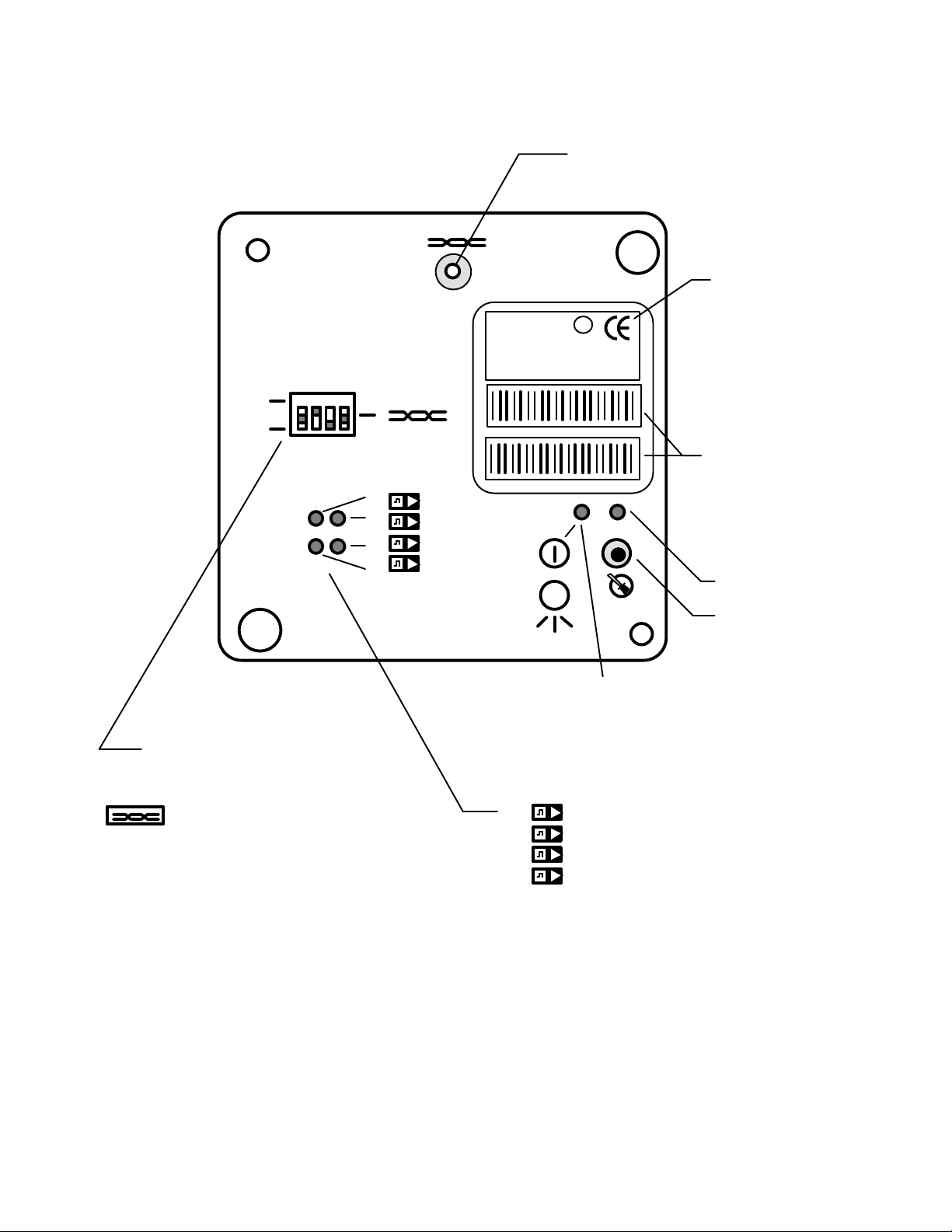
L
o
n
P
o
i
n
t
™
I
n
t
e
r
f
a
c
e
Network Access Jack; Use
Digital Output 4 Switch
4
With Echelon PCC-10 Cable
Model 78303
LonPoint Interface
E
DO-10
MODEL 41200 9745
SW VERSION 3.0
ID NUMBER
OUTPUT: 0-12VDC, 25mA EACH
U
c
L
®
m
us
LISTED 178K
ENERGY MANAGEMENT
EQUIPMENT SUBASSEMBLY
1 2 3 4
1 2 3 4
1
0
DO-10 MODEL 41200 ID NUMBER
Model and Software
Revision
Peel-Off Code 39
DO-10 MODEL 41200 ID NUMBER
1
2
3
4
Format Bar Code of
LonPoint Interface
Neuron Chip ID
Number
Service LED
Service Switch
Hand/Off/Auto Switch
1 ON (Hand)
0 OFF (Off)
Network Controlled (Auto)
1
Digital Output 1 Switch
2
Digital Output 2 Switch
3
Digital Output 3 Switch
Figure 7.1 LonPoint DO-10 Digital Output Module - Front Panel
Power/Wink LED:
Power ON: Illuminated Continuously
Wink: Flashing
Digital Output Status LEDs
1
2
3
4
Digital Output 1 LED
Digital Output 2 LED
Digital Output 3 LED
Digital Output 4 LED
LonPoint Hardware Guide 7-3
Page 82

The DO-10 module is installed in a Type 1 or Type 1D Base Plate. Wiring connections
to the DO-10 module are presented in table 7.1. Specifications for the DO-10 module
are shown in table 7.2.
Table 7.1 DO-10 Digital Output Module Wiring Connections
Screw Terminal Wiring Connection
1 and 2 Incoming network wiring, TP/FT-10 channel, polarity-
insensitive
3 and 4 Outgoing network wiring, TP/FT-10 channel, polarity-
insensitive
5 Unused
6 and 7 Incoming power wiring, 16-30VAC or VDC, 3.2 to 6.5VA
depending on load maximum, polarity-insensitive. If using DC
power, it is good practice to maintain continuity of the power
polarity throughout the network. Terminals 6 and 8 should be
the same polarity, and terminals 7 and 9 should be the same
polarity.
10 + output of digital output 1
11 - output of digital output 1 (common to all outputs)
12 + output of digital output 2
13 - output of digital output 2 (common to all outputs)
14 Unused
15 + output of digital output 3
16 - output of digital output 3 (common to all outputs)
17 + output of digital output 4
18 - output of digital output 4 (common to all outputs)
Table 7.2 LonPoint DO-10 Digital Output Module Specifications
Function Description
Processor/memory Neuron 3150 Chip, 10MHz, 56K flash memory
Service function Recessed service switch, service LED, power/wink LED. Dual
tear-off bar-code Neuron ID self-adhesive tag for application to
red-line drawings in the field
I/O 4 digital outputs, 0-12V, 100mA source/sink maximum on any
one output, 110mA source/400mA sink combined; separate
status LEDs for each output; separate hand/off/auto front
panel DIP switches for each output
I/O isolation 100V, transformer isolation. Outputs are isolated from the input
power and the network but not from each other.
Transceiver type FTT-10A with blocking capacitors for compatibility with link
power channel
Network connector Phone plug connector accessible from front panel
Input power 16-30VAC or VDC @ 3.2 to 6.5VA depending on load,
internally isolated power supply
Mounting Type 1 or Type 1D Base Plate
Temperature -40 to +85°C, operating and non-operating
Humidity 10 to 95% RH @ 50°C
7-4 Installing the DO-10 Digital Output
Module
Page 83

EMI FCC A, CE Mark
Safety agency UL 916
Function Blocks Node object (1), digital output open-loop actuator objects (4),
digital encoder controller objects (2), analog function block
controller objects (2), type translators (6)
Software Configuration Wide variety of LONMARK Standard Configuration Parameter
Types supported by direct memory read/write function of LNS
compatible network management tools
DO-10 Module Software Settings
The software settings of the DO-10 module are described in the LonPoint
Application and Plug-In Guide
Installing the DO-10 Module
Installation of the DO-10 module involves the following steps:
1. Ensure that the Base Plate has been wired and installed correctly, and is
securely fastened to the electrical enclosure.
2. Check for continuity on all network and power wiring. Ensure that the correct
actuators are connected to the correct Base Plate I/O terminals.
3. Make certain that all network channels are terminated with the correct number
and type of Terminator.
4. Insert the DO-10 module into Base Plate by aligning the network access jack on
the DO-10 with the arrow head on the Base Plate (the arrow should point in the
direction of the jack), and then pressing firmly to ensure that the module is
properly seated in its mating Base Plate connector.
5. The DO-10 module can be hot-plugged: there is no need to disconnect power
when installing the module. If power is present then the Power LED will
illuminate continuously. If power is not present then the Power LED will remain
off. The hand/off/auto switches will not function unless the DO-10 module is
powered.
6. Securely attach the DO-10 module to the Base Plate by screwing the two
Echelon 205-0130-01 screws (8-32 [M8], 3/8” [9.5mm]) into the threaded inserts
in the Base Plate. Use approximately 4 lbs. in/0.5Nm torque on the screws.
7. Follow the node configuration procedure described in the LonPoint Application
and Plug-In Guide to configure the software in the DO-10 module.
8. See Troubleshooting for assistance with improper DO-10 module operation.
LonPoint Hardware Guide 7-5
Page 84

7-6 Installing the DO-10 Digital Output
Module
Page 85

8
Installing the AI-10 Analog Input Module
This chapter describes the process of installing the Model 41300 AI-10
Analog Input Module.
LonPoint Hardware Guide 8-1
Page 86
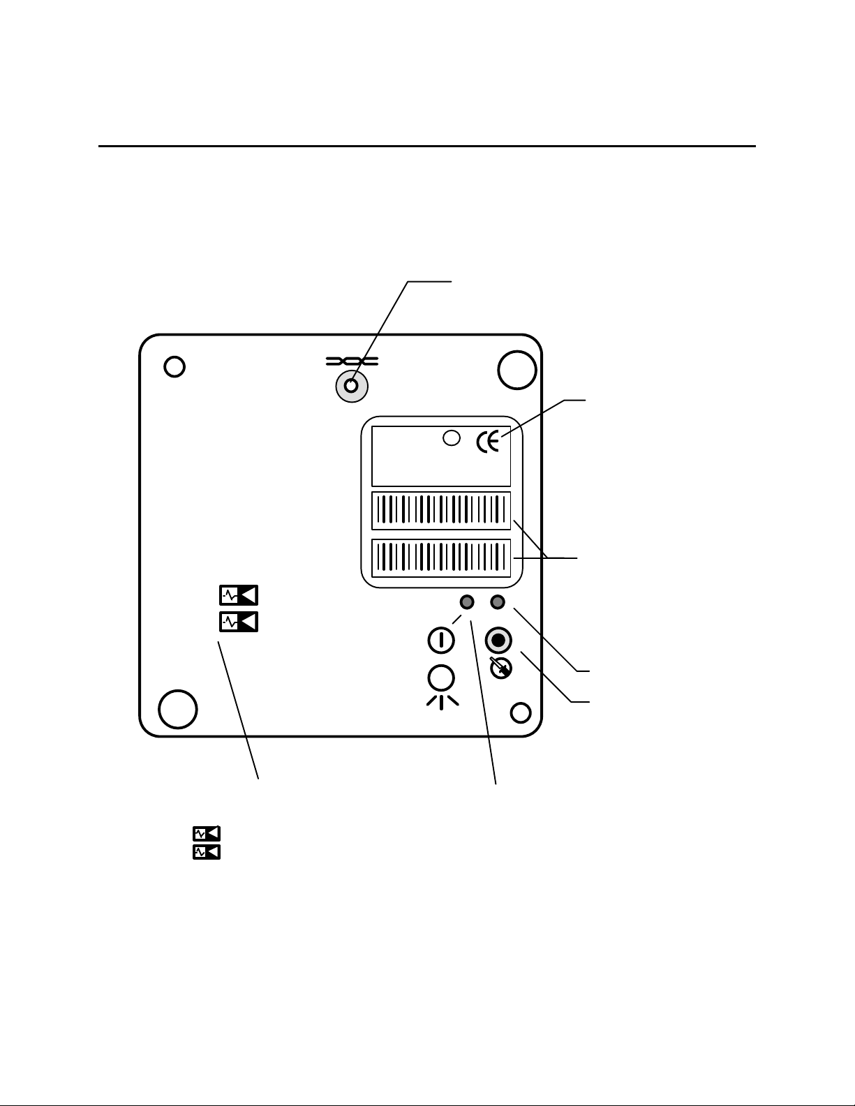
LonPoint AI-10 Analog Input Module
L
o
n
P
o
i
n
t
™
I
n
t
e
r
f
a
c
e
Analog Input 2
2
The front panel of the AI-10 module is shown in figure 8.1. There are no front panel
LEDs associated with the inputs, however, there are user-configured jumper blocks
that must be set correctly for each analog input.
Network Access Jack; Use
With Echelon PCC-10 Cable
Model 78303
LonPoint Interface
E
U
®
c us
L
AI-10
MODEL 41300 9760
SW VERSION 3.0
ID NUMBER
INPUT: 0-20VDC, 0-24mA EACH
AI-10 MODEL 41300 ID NUMBER
AI-10 MODEL 41300 ID NUMBER
1
2
m
LISTED 178K
ENERGY MANAGEMENT
EQUIPMENT SUBASSEMBLY
Model and Software
Revision
Peel-Off Code 39
Format Bar Code of
LonPoint Interface
Neuron Chip ID
Number
Service LED
Service Switch
Analog Input Identifier
(No LEDs For Analog Inputs)
1
Analog Input 1
Figure 8.1 LonPoint AI-10 Analog Input Module - Front Panel
Power/Wink LED:
Power ON: Illuminated Continuously
Wink: Flashing
8-2 Installing the AI-10 Analog Input Module
Page 87
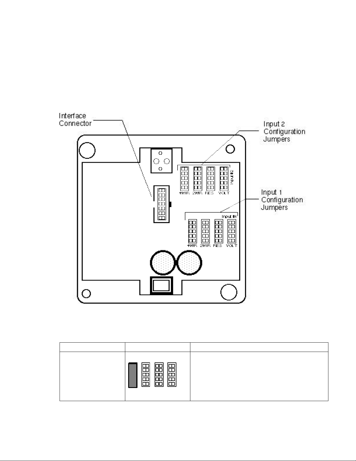
The AI-10 module includes four 5 x 2 jumper blocks for each input. These jumper
blocks, labeled 2WIR, 4WIR, RES, and VOLT, are used to configure the module for
the type of analog input signal that will be monitored (figure 8.2); using an incorrect
jumper setting will result in improper input supervision and could cause damage to
the module and/or the sensor. Each of the two sensor inputs may be configured
differently. Table 8.1 presents the correct jumper position for different types of
analog inputs.
Figure 8.2 LonPoint AI-10 Jumper Block Settings - Rear Panel
Table 8.1 AI-10 Analog Input Module Wiring Connections
Function Jumper Position Description
Input 1
4-Wire 0-24mA
Remotely Powered
Input #1
This setting is used for connecting 0-20mA,
4-20mA, 4-24mA, or 0-24mA intelligent
transmitters that are powered by either their own
power supply or a separate power supply. The
maximum allowable current range is 0-25mA. In
4WIR RES2WIR VOLT
this setting the AI-10 does not supply power to the
current loop.
LonPoint Hardware Guide 8-3
Page 88
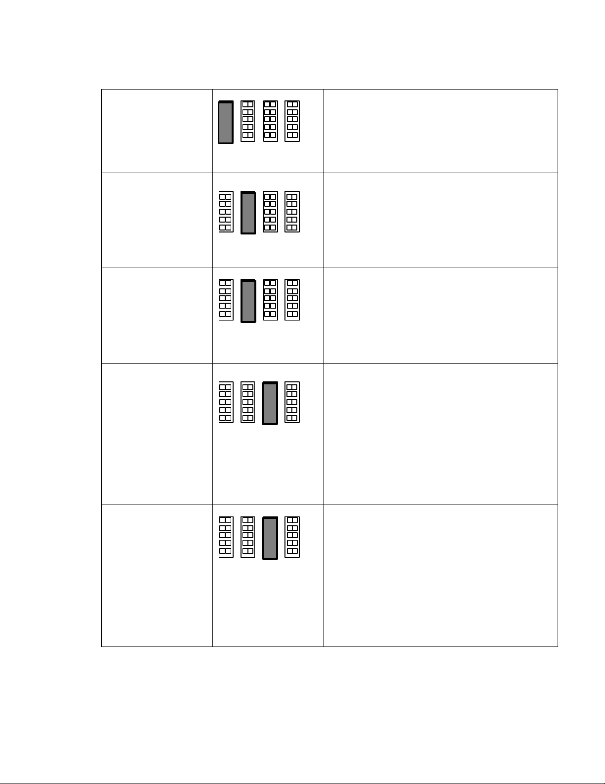
Input 2
Input #2
4WIR RES2WIR VOLT
Input #2
4WIR RES2WIR VOLT
Input #2
4WIR RES2WIR VOLT
4-Wire 0-24mA
Remotely Powered
Input 1
2-Wire 4-20mA
Current Loop Powered
Input 2
2-Wire 4-20mA
Current Loop Powered
Input 1
Passive Resistive
Sensor
Input 2
Passive Resistive
Sensor
Input #1
4WIR RES2WIR VOLT
4WIR RES2WIR VOLT
Input #1
This setting is used for connecting 0-20mA,
4-20mA, 4-24mA, or 0-24mA intelligent
transmitters that are powered by either their own
power supply or a separate power supply. The
maximum allowable current range is 0-25mA. In
this setting the AI-10 does not supply power to the
current loop.
This setting is used for connecting 4-20mA
intelligent transmitters that are powered by the
current loop provided by the AI-10 module. The
maximum allowable current range is 0-25mA in
order to permit fault conditions to be detected
(open as 0mA, short circuit as 25mA). This mode
is not suitable for measuring passive resistive
devices. Minimum loop voltage is 12VDC.
This setting is used for connecting passive
resistive sensors to the AI-10 module. Resistance
is measured by passing a controlled current
through the sensor and then measuring the
resulting voltage across the AI-10 screw terminals.
Measurements of passive resistive devices may
only be taken using the RES mode - the 2WIR
mode is not suitable for this purpose. See text
below for a discussion of the range and software
settings for the RES mode. In this mode 3.5V is
provided on the (+) terminal and programmable
current sink (25mA or 400mA on the (-) terminal).
8-4 Installing the AI-10 Analog Input Module
Page 89
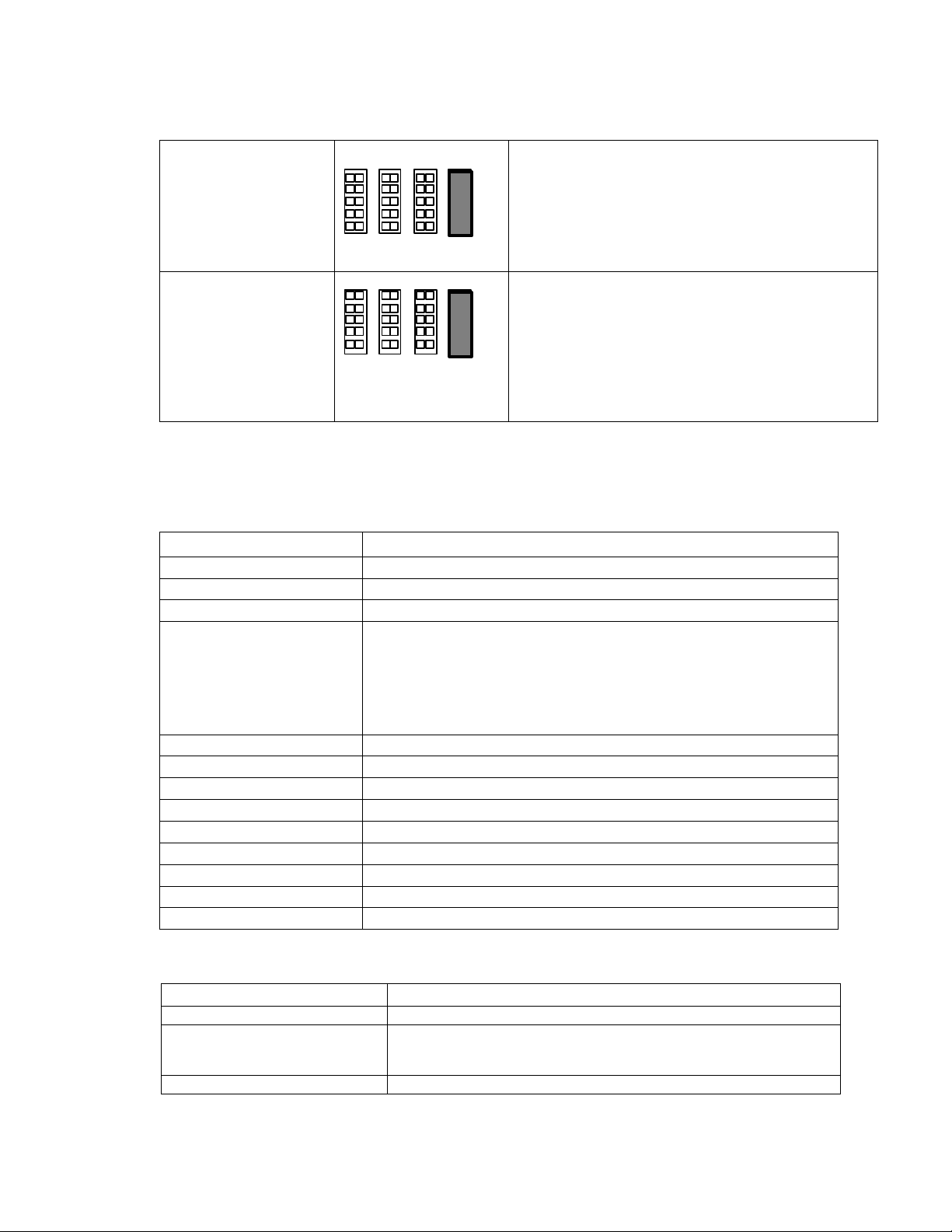
Input 1
4WIR RES2WIR VOLT
Input #2
4WIR RES2WIR VOLT
Voltage Sensing
Input #1
This setting is used for connecting an intelligent
transmitter that generates a 0-5V, 0-10V, or 0-20V
output. See text below for a discussion of the
range and software settings for the VOLT mode.
This setting also can be used to measure passive
thermocouplers. The input resistance of the
± 0.3%.
Input 2
Voltage Sensing
analog input is 7.246K Ohms
This setting is used for connecting an intelligent
transmitter that generates a 0-5V, 0-10V, or 0-20V
output. See text below for a discussion of the
range and software settings for the VOLT mode.
This setting also can be used to measure passive
thermocouplers. In this mode 3.5V is provided on
the (+) terminal and programmable current sink
(25mA or 400mA on the (-) terminal).
The AI-10 module is installed in a Type 1 Base Plate. Wiring connections to the AI-10 module are
presented in table 8.2. Specifications for the AI-10 module are shown in table 8.3.
Table 8.2 AI-10 Analog Input Module Wiring Connections
Screw Terminal Wiring Connection
1 and 2 Incoming network wiring, TP/FT-10 channel, polarity-insensitive
3 and 4 Outgoing network wiring, TP/FT-10 channel, polarity-insensitive
5 Unused
6 and 7 Incoming power wiring, 16-30VAC or VDC, 2.1VA for all mdoes
except 2-wire mode (4.5VA) maximum, polarity-insensitive. If
using DC power, it is good practice to maintain continuity of the
power polarity throughout the network. Terminals 6 and 8 should
be the same polarity, and terminals 7 and 9 should be the same
polarity.
10 + input of analog input 1
11 - input of analog input 1
12 + input of analog input 2
13 - input of analog input 2
14 Unused
15 Unused
16 Unused
17 Unused
18 Unused
LonPoint Hardware Guide 8-5
Table 8.3 LonPoint AI-10 Analog Input Module Specifications
Function Description
Processor/memory Neuron 3150 Chip, 10MHz, 56K flash memory
Service function Recessed service switch, service LED, power/wink LED. Dual
tear-off bar-code Neuron ID self-adhesive tag for application to
red-line drawings in the field
I/O 2 independent 16-bit resolution analog inputs
Page 90

I/O type 0 to 156mV
0 to 625mV
0 to 10V
0 to 20V
0 to 24mA
0 - 12.5µA
0 - 781µA
0 - 19.5µA
Resistive transducer ranging from 100• to 15k•, nominal
I/O resolution 0 to 20VDC: 0.3mV resolution
0 to 24mA: 0.37µA resolution
I/O isolation 100V, transformer isolation. Inputs are isolated from the input
power and the network but not from each other.
Transceiver type FTT-10A with blocking capacitors for compatibility with link
power channel
Network connector Phone plug connector accessible from front panel
Input power 16-30VAC or VDC, internally isolated power supply—2.1VA for
all modes except 2-wire mode (4.5VA)
Mounting Type 1 or Type 1D Base Plate
Temperature -40 to +85°C, operating and non-operating
Humidity 10 to 95% RH @ 50°C
EMI FCC A, CE Mark
Safety agency UL 916
Function Blocks Node object (1), analog input open-loop sensor objects (2),
digital encoder controller objects (2), analog function block
controller objects (4), type translators (4)
Software Configuration Wide variety of LONMARK Standard Configuration Parameter
Types supported by direct memory read/write function of LNS
compatible network management tools
AI-10 Module Software Settings
The software settings of the AI-10 module are described in the LonPoint Application
and Plug-In Guide.
Installing the AI-10 Module
Installation of the AI-10 module involves the following steps:
1. Ensure that the Base Plate has been wired and installed correctly, and is
securely fastened to the electrical enclosure.
2. Check for continuity on all network and power wiring. Ensure that the correct
sensors are connected to the correct Base Plate I/O terminals.
3. Make certain that all network channels are terminated with the correct number
and type of Terminator.
4. Insert the AI-10 module into Base Plate by aligning the network access jack on
the AI-10 with the arrow head on the Base Plate (the arrow should point in the
8-6 Installing the AI-10 Analog Input Module
Page 91

direction of the jack), and then pressing firmly to ensure that the module is
properly seated in its mating Base Plate connector.
5. The AI-10 module can be hot-plugged: there is no need to disconnect power when
installing the module. If power is present then the Power LED will illuminate
continuously. If power is not present then the Power LED will remain off.
LonPoint Hardware Guide 8-7
Page 92

6. Securely attach the AI-10 module to the Base Plate by screwing the two Echelon
205-0130-01 screws (8-32 [M8], 3/8” [9.5mm]) into the threaded inserts in the
Base Plate. Use approximately 4 lbs. in/0.5Nm torque on the screws.
7. Follow the node configuration procedure described in the LonPoint Application
and Plug-In Guide to configure the software in the AI-10 module.
8. See Troubleshooting for assistance with improper AI-10 module operation.
8-8 Installing the AI-10 Analog Input Module
Page 93

LonPoint Hardware Guide 8-9
Page 94

9
Installing the AO-10 Analog Output
Module
This chapter describes the process of installing the Model 41400
AO-10 Analog Output Module.
LonPoint Hardware Guide 9-1
Page 95

LonPoint AO-10 Analog Output Module
L
o
n
P
o
i
n
t
™
I
n
t
e
r
f
a
c
e
Analog Output 2
2
The front panel of the AO-10 module is shown in figure 9.1. There are no
front panel LEDs associated with the outputs, however, there are userconfigured jumper blocks that must be set correctly for each analog output.
Network Access Jack; Use
With Echelon PCC-10 Cable
Model 78303
E
AO-10
MODEL 41400 9760
SW VERSION 3.0
ID NUMBER
OUTPUT: 1012VDC, 0-20mA EACH
AO-10 MODEL 41400 ID NUMBER
U
c
®
L
m
us
LISTED 178K
ENERGY MANAGEMENT
EQUIPMENT SUBASSEMBLY
LonPoint Interface
Model and Software
Revision Numbers
AO-10 MODEL 41400 ID NUMBER
1
2
Format Bar Code of
LonPoint Interface
Neuron Chip ID
Number
Service LED
Service Switch
Peel-Off Code 39
Analog Output Identifier
(No LEDs For Analog Outputs)
1
Analog Output 1
Figure 9.1 LonPoint AO-10 Analog Input Module - Front Panel
The AO-10 module includes two 4 x 2 jumper blocks for each output. These jumper
blocks, labeled 0-10V and 4-20mA, are used to configure the module for the type of
analog output signal that will be generated (figure 9.2); using an incorrect jumper
setting will result in improper output signals. Each of the two outputs may be
Power/Wink LED:
Power ON: Illuminated Continuously
Wink: Flashing
9-2 Installing the AO-10 Analog Output
Module
Page 96
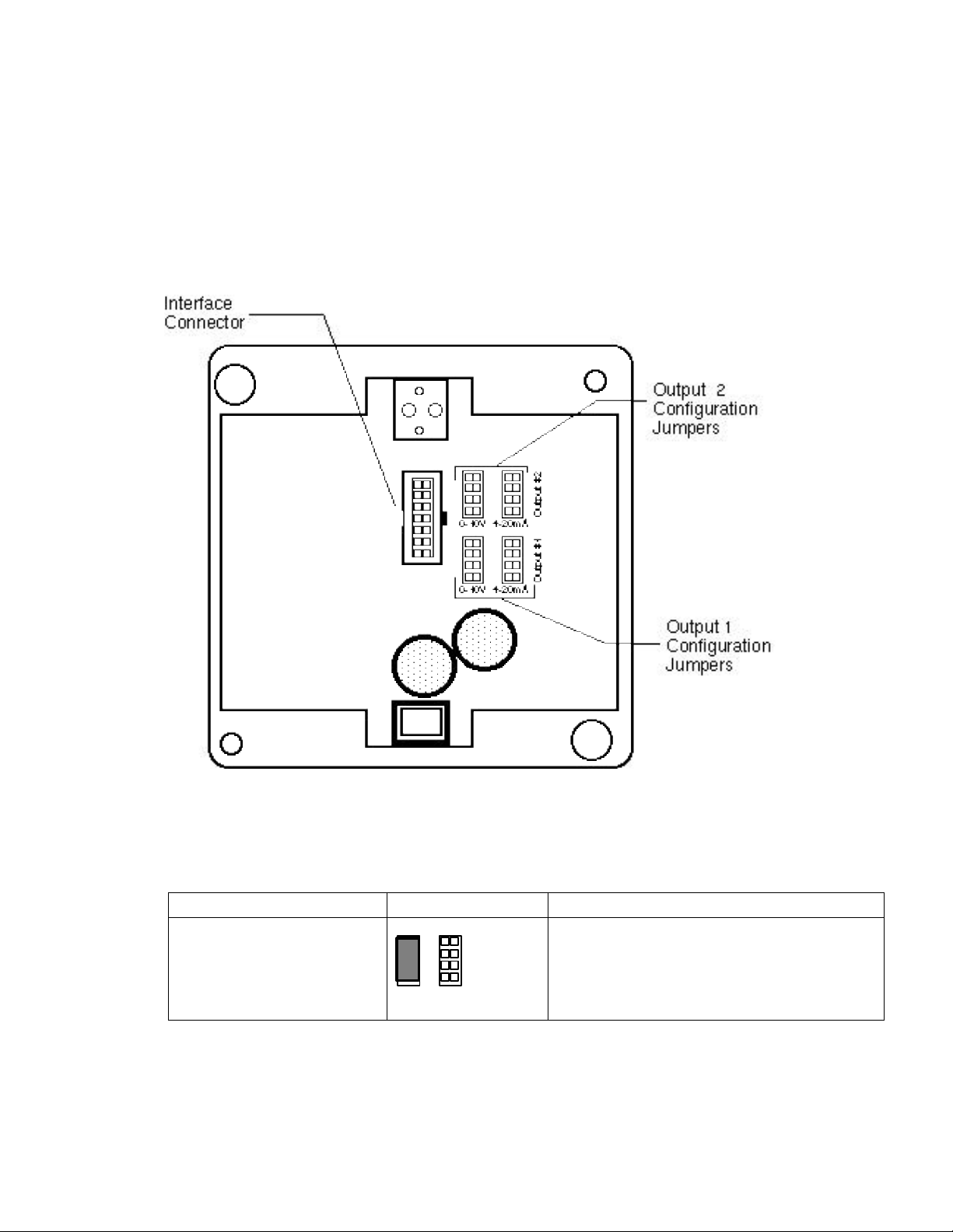
configured differently. Table 9.1 presents the correct jumper position for different
Output #1
0-10V 4-20mA
types of analog outputs.
The AO-10 sources, but does not sink, current. For wiring simplicity, 4-20mA actuators
attached to the AO-10 module should be operated in 2-wire mode, provided that they can
operate at 12V or less. Actuators that require >12V across their terminals should be
operated in a 4-wire mode and powered from a separate power supply.
Figure 9.2 LonPoint AO-10 Jumper Block Settings - Rear Panel
Table 9.1 AO-10 Analog Output Module Wiring Connections
Function Jumper Position Description
Output 1
0-10V Output
This setting is used for generating a 0-10V
output from the 12-bit D/A converter via a
voltage amplifier. Output load may be as low
as 1K Ohms.
LonPoint Hardware Guide 9-3
Page 97
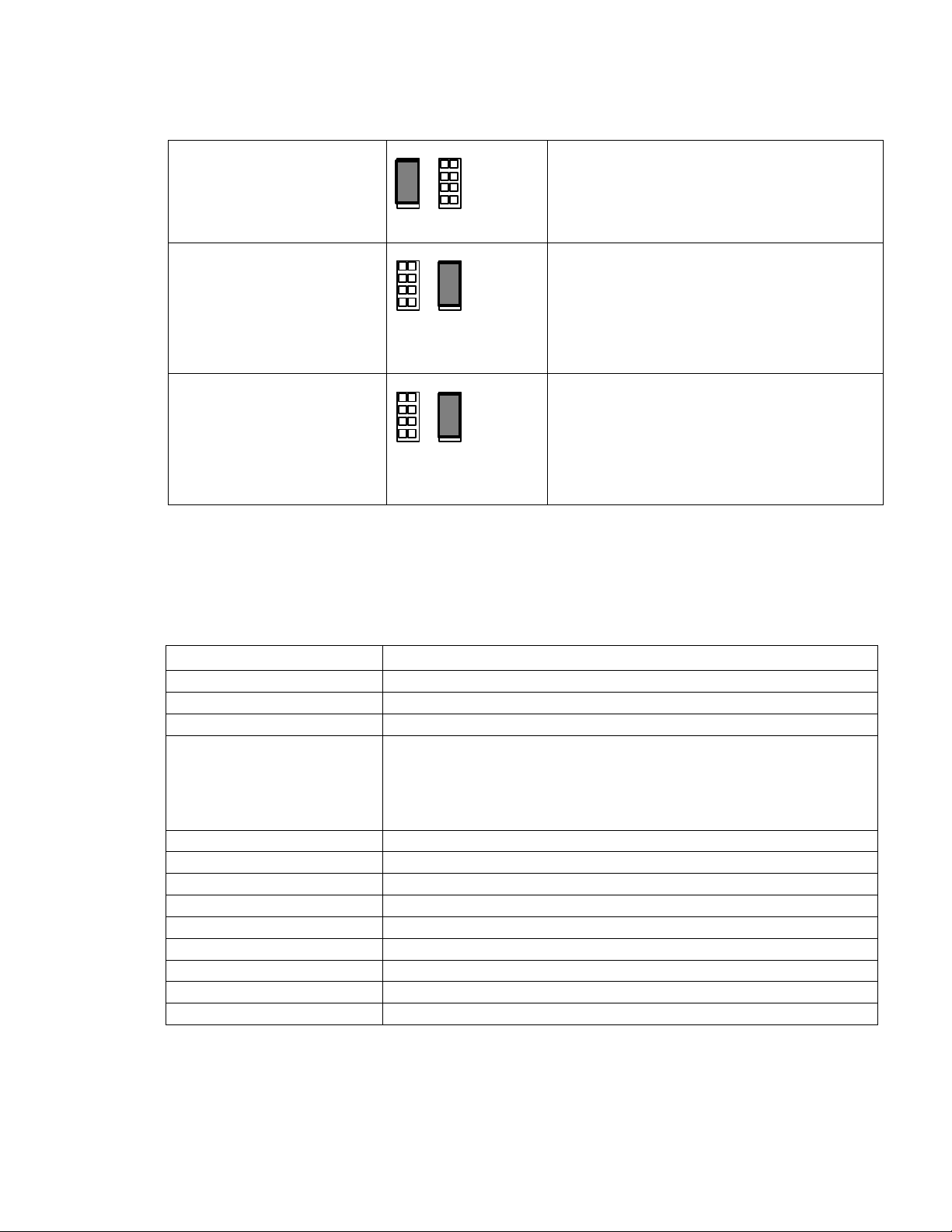
Output 2
Output #2
0-10V 4-20mA
Output #1
0-10V 4-20mA
Output #2
0-10V 4-20mA
0-10V Output
This setting is used for generating a 0-10V
output from the 12-bit D/A converter via a
voltage amplifier. Output load may be as low
as 1K Ohms.
Output 1
Programmable range within
0-20mA
This setting is used for generating any output
range from 0-20mA (software
programmable), i.e., 4-20mA from the 12-bit
D/A converter via a current amplifier. The
AO-10 sources current only - it cannot
function as a current sink. Output load may
be as low as 1K Ohms.
Output 2
Programmable range within
0-20mA
This setting is used for generating any output
range from 0-20mA (software
programmable), i.e., 4-20mA from the 12-bit
D/A converter via a current amplifier. The
AO-10 sources current only - it cannot
function as a current sink. Output load may
be as low as 1K Ohms.
The AO-10 module is installed in a Type 1 or Type 1D Base Plate. Wiring
connections to the AO-10 module are presented in table 9.2. Specifications for the
AO-10 module are shown in table 9.3.
Table 9.2 AO-10 Analog Output Module Wiring Connections
Screw Terminal Wiring Connection
1 and 2 Incoming network wiring, TP/FT-10 channel, polarity-insensitive
3 and 4 Outgoing network wiring, TP/FT-10 channel, polarity-insensitive
5 Unused
6 and 7 Incoming power wiring, 16-30VAC or VDC @4.2VA, polarity-
insensitive. If using DC power it is good practice to maintain
continuity of the power polarity throughout the network. Terminals 6
and 8 should be the same polarity, and terminals 7 and 9 should be
the same polarity.
10 + input of analog output 1
11 - input of analog output 1
12 + input of analog output 2
13 - input of analog output 2
14 Unused
15 Unused
16 Unused
17 Unused
18 Unused
Table 9.3 LonPoint AO-10 Analog Output Module Specifications
9-4 Installing the AO-10 Analog Output
Module
Page 98

Function Description
FTT-10A with blocking capacitors for compatibility link power channel
Processor/memory Neuron 3150 Chip, 10MHz, 56K flash memory
Service function Recessed service switch, service LED, power/wink LED. Dual tear-
off bar-code Neuron ID self-adhesive tag for application to red-line
drawings in the field
I/O 2 independent 12-bit resolution analog outputs
I/O type 0-10V into 1k•, minimum, or 0 to 20mA @ 0-12V
I/O resolution 0-10VDC: 2.5mV resolution
0-20mA: 5.0µA resolution
I/O isolation 100V, transformer isolation. Outputs are isolated from the input
power and the network but not from each other.
Transceiver type
Network connector Phone plug connector accessible from front panel
Input power 16-30VAC or VDC @ 4.2VA, internally isolated power supply
Mounting Type 1 or Type 1D Base Plate
Temperature -40 to +85°C, operating and non-operating
Humidity 10 to 95% RH @ 50°C
EMI FCC A, CE Mark
Safety agency UL 916
Function Blocks Node object (1), analog output open-loop actuator objects (2), digital
encoder controller objects (1), analog function block controller
objects (2), PID controller objects (2), type translators (3)
Software Configuration Wide variety of LONMARK Standard Configuration Parameter Types
supported by direct memory read/write function of LNS compatible
network management tools
AO-10 Module Software Settings
The software settings of the AO-10 module are described in the LonPoint
Application and Plug-In Guide.
Installing the AO-10 Module
Installation of the AO-10 module involves the following steps:
1. Ensure that the Base Plate has been wired and installed correctly, and is
securely fastened to the electrical enclosure.
2. Check for continuity on all network and power wiring. Ensure that the correct
actuators are connected to the correct Base Plate I/O terminals.
3. Make certain that all network channels are terminated with the correct number
and type of Terminator.
4. Insert the AO-10 module into the Base Plate by aligning the network access jack
on the AO-10 with the arrow head on the Base Plate (the arrow should point in
the direction of the jack), and then pressing firmly to ensure that the module is
properly seated in its mating Base Plate connector.
LonPoint Hardware Guide 9-5
Page 99

5. The AO-10 module can be hot-plugged: there is no need to disconnect power
when installing the module. If power is present then the Power LED will
illuminate continuously. If power is not present then the Power LED will remain
off.
9-6 Installing the AO-10 Analog Output
Module
Page 100

6. Securely attach the AO-10 module to the Base Plate by screwing the two
Echelon 205-0130-01 screws (8-32 [M8], 3/8” [9.5mm]) into the threaded inserts
in the Base Plate. Use approximately 4 lbs. in/0.5Nm torque on the screws.
7. Follow the node configuration procedure described in the LonPoint Application
and Plug-In Guide to configure the software in the AO-10 module.
8. See Troubleshooting for assistance with improper AO-10 module operation.
LonPoint Hardware Guide 9-7
 Loading...